Embed Size (px)
Citation preview

IEEE Waves and DevicesPhoenix Chapter:
Space Communications
Bob Anderson24 June 2010

2
Introduction
� Why communicate?� Must control the spacecraft/experiment
� In human spaceflight, lives depend on it
� Must track the craft� Ranging (distance/position)� Relative speed (Doppler effect)
� Collect science data� Usually the purpose of the mission in the first
place

3
Communications
TRANSMITTER RECEIVER
TRANSMITTERRECEIVER
COMMUNICATIONSDID THE RECEIVER RECEIVE THE SIGNAL?DID THE RECEIVER PROCESS THE SIGNAL CORRECTLY?DID I RECEIVE THE CORRECT TELEMETRY/DATA BACK?

4
Radio
AUDIO RF CARRIER AM MODULATED(TIME DOMAIN)
AM MODULATED(FREQUENCY DOMAIN)
Po
f
PULSE CODEAUDIO PCM(TIME DOMAIN)
PCM(FREQUENCY DOMAIN)
Po
f

5
TT&C
� Telemetry Tracking and Command (TT&C)� Monitor received telemetry
� Health and mode analysis
� Perform tracking� Distance and position measurements� Doppler measurements – spacecraft velocity
� Send commands� Command the spacecraft for attitude, position, and
miscellaneous functions

6
Transponder
TRANSMITTER RECEIVER
TRANSMITTERRECEIVER
BENT PIPETRANSPONDER TRANSMITS EXACTLY WHAT IT RECEIVES
GROUND STATION TRANSPONDER

7
Transponder
TRANSMITTER RECEIVER
TRANSMITTERRECEIVER
TWO WAYTRANSPONDER RECEIVES COMMANDSTRANSMITS SCIENCE DATA AND TELEMETRY
GROUND STATION TRANSPONDER

8
U.S. Space Program Timeline
NRL V2, SPUTNIK, EXPLORER, PIONEER, MERCURY
RANGER, GEMINISpace Programs(USA) APOLLO, LUNAR ORBITER, MARINER, SURVEYOR
SKY LAB, PIONEER 10, MARINER 10, HELIOSVIKING, VOYAGER I, II, PIONEER VENUS,INTERNATIONAL SUN-EARTH, SOLAR MAXIMUM
1956-1962 1963-1965 1966-1967 1968-1969 1970-1975 1976-1980TDRSS I, SPACE SHUTTLE
GD (Motorola) contributions
VOYAGER, NASA STDN
S-BAND SPECIAL TEST EQUIPMENT, MARINER MARS
APOLLO TRANSPONDERS, LUNAR ORBITER
RANGER AND MARINER TRANSPONDERS, APOLLO STUDY
JPL X-BAND, RANGER AND MARINER TRANSPONDERS
Vanguard

9
U.S. Space Program Timeline
MAGELLAN, GALILEO, HUBBLE SPACE TELESCOPE, ULYSSES
Space Programs MARS OBSERVER, CLEMENTINE, SOHO(USA)
SPACE STATION, NEAR, MARS GLOBAL SURVEYOR, MARS PATHFINDER, CASSINI/HUYGENSLUNAR PROSPECTOR, DEEP SPACE I, STARDUST, MARS POLAR LANDER
IMAGE, MARS ODYSSEY, GENESIS, CONTOUR, MARS EXPRESSMRO, JUNO, LRO, STEREO, DAWN (NEW HORIZONS), MARS LANDER
1981-1985 1986-1990 1991-1995 1996-2000 2001-2005 2006-2010MRO, JUNO, LRO, STEREO, DAWN (NEW HORIZONS), MARS LANDER
GD (Motorola) contributions
SDST, CASSINI, MARS ODYSSEY, STARDUST,SPITZER SPACE TELESCOPE, MARS ROVERS, DEEP IMPACT, MERCURY MESSINGER, MARS EXPRESS
DST, TDRSS IV, SPACE STATION, NEAR, MARS GLOBAL SURVEYOR, MARS PATHFINDER, CASSINI/HUYGENS,DEEP SPACE I, STARDUST, MARS POLAR LANDER, MARS ODYSSEY
IRIDIUM, MARS OBSERVER, SOHO
JPL DSN 3, MAGELLAN, GALILEO, HUBBLE SPACE TELESCOPE
JPL DSN, TDRSS II, III
10
)()()/()/()()()()( dBLdBLHzdBWkTsbitdBRdBN
EdBiGdBWEIRPdBM os
reqdo
br −−−−−
−+=
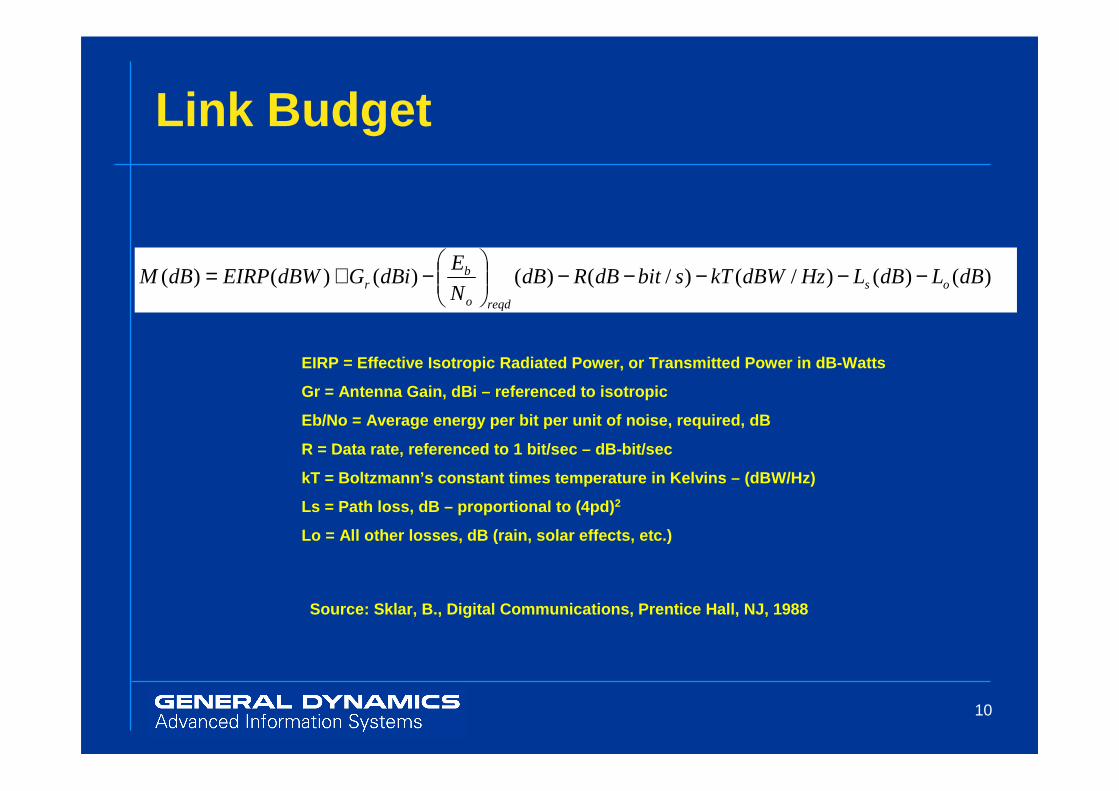
Link Budget
EIRP = Effective Isotropic Radiated Power, or Trans mitted Power in dB-Watts
Gr = Antenna Gain, dBi – referenced to isotropic
Eb/No = Average energy per bit per unit of noise, r equired, dB
R = Data rate, referenced to 1 bit/sec – dB-bit/sec
kT = Boltzmann’s constant times temperature in Kelv ins – (dBW/Hz)
Ls = Path loss, dB – proportional to (4pd) 2
Lo = All other losses, dB (rain, solar effects, etc .)
Source: Sklar, B., Digital Communications, Prentice Hall, NJ, 1988
11
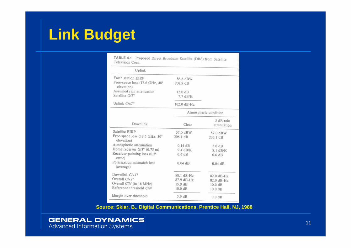
Link Budget
Source: Sklar, B., Digital Communications, Prentice Hall, NJ, 1988

12
Link Budget
Source: Sklar, B., Digital Communications, Prentice Hall, NJ, 1988

13
Van Allen Radiation Belt
Discovered by Explorer I and II in
1958 under direction of Dr. James Van Allen.
A satellite shielded by 3 mm of aluminum in
an elliptic orbit (200 by 20,000 miles) passing through the radiation
belts will receive about 2,500 rem (25 Sv) per
year. Almost all radiation will be
received while passing the inner belt. 25 Sv =
25 J/kg.
The inner belt is 60 to 6,200 miles high
Source: NASA

14
South Atlantic Anomaly
The South Atlantic Anomaly (SAA) refers to the area where the Earth's inner Van Allen radiation belt comes closest to the Earth’s surface. This leads to an increased flux of energetic particles in this region and exposes orbiting satellites to higher than usual levels of radiation. The effect is caused by the non-concentricity of the Earth and its magnetic dipole, and the SAA is the near-Earth region where the Earth’s magnetic field is weakest.
Source: NASASAA

15
Space Debris Problem
Source: National Geographic
July 2010

16
Space Debris Problem
Source: National Geographic
July 2010

17
Space Debris Problem
Source: National Geographic
July 2010

18
Earth Satellite Communications
� Geo-synchronous/stationary� Weather� Broadcast� TDRSS
� Earth orbital� IRIDIUM� Scientific Study
� Space Station

19
Weather
GOES-8 Satellite and Weather Map (22,236 mi. High O rbit)Source: NASA

20
TDRSS
Tracking and Data Satellite System (TDRSS)Source: NASA/GD (Motorola)

21
TDRSS
Tracking and Data Satellite System (TDRSS)Source: NASA
22
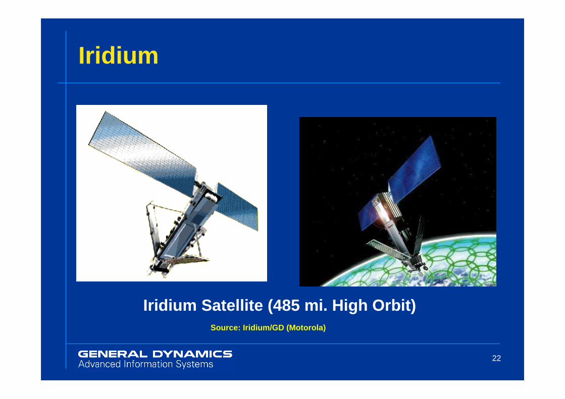
Iridium
Iridium Satellite (485 mi. High Orbit)Source: Iridium/GD (Motorola)

23
Space Station
Space Station (181 – 189 mi. high Orbit)Source: NASA/GD (Motorola)

24
Space Station
Space StationSource: NASA

25
Space Station
Space StationSource: NASA/JSC

26
Manned Missions Communications
� Mercury
� Gemini� Apollo
� Space Shuttle� Space Station

27
Manned Missions
� GD (Motorola) supported various phases of Apollo program� Unified s-band transponder� Command module unified amplifier
� Functional communications link that carried astronauts’ pictures and voice from the Moon’s surface back to Earth

28
Apollo
Apollo Command Module Unified S-Band Transponder (manufactured by Motorola, Inc., Military Electronics Division, Scottsdale, Ariz.). The Unified S-Band Transponder was the only method of exchanging voice communications, tracking, biomedical, and ranging, transmission of pulse code modulated (PCM) data and television, and reception of uplinked data from Mission Control once the Apollo Command Module was outside a range of 1500 nautical miles and line of sight from Manned Space Flight Network (MSFN) ground stations strung around the Earth (within that range, VHF was available). The term "Unified" is applicable because the communications system combined the functions of (signal) acquisition, telemetry, command, voice, television and tracking on one radio link. The Unified S-Band Equipment (USBE) onboard the Apollo Command Module, Lunar Module, Lunar Rover were absolutely critical to the successful execution of the Apollo program; and reliability was assured through the implementation of full redundant, heavily tested design.
Source: SpaceAholic.com

29
Apollo
Source: SpaceAholic.com
APOLLO COMMAND MODULE UNIFIED S-BAND TRANSPONDER
30
Apollo
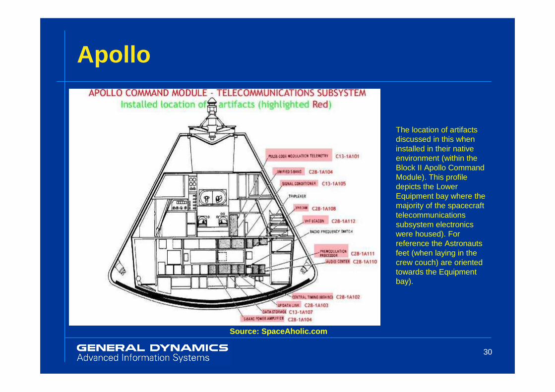
Source: SpaceAholic.com
The location of artifacts discussed in this when installed in their native environment (within the Block II Apollo Command Module). This profile depicts the Lower Equipment bay where the majority of the spacecraft telecommunications subsystem electronics were housed). For reference the Astronauts feet (when laying in the crew couch) are oriented towards the Equipment bay).

31
Apollo
Source: SpaceAholic.com
Motorola Corporation News Bureau release photograph of Apollo Command Module Unified S-Band Equipment (USBE) Transponder - the release reads: "The two-way radio on the Apollo Command Module requires less power to communicate with Earth from the vicinity of the Moon then the power used by the light bulbs in your refrigerator. The small unit, produced by Motorola Government Electronics Division, is the only communications link with the Apollo Command Module crew has with Earth from beyond 30,000 miles away providing all voice contact, TV pictures and mission data. Lovely Motorola technician Mandy Biondi shows the sophisticated unit which has functioned perfectly on every mission." (Image courtesy Motorola/GDAIS).

32
Space Probe Communications
� Early missions� Sputnik� Explorer� Ranger� Mariner� Pioneer� Surveyor� Voyager I, II� Magellan� Galileo

33
Sputnik
Source: University of Colorado Students for the Exploration and Development of Space
Launched October 4, 1957;
operated for 3 months

34
Vanguard I
Source: NASA
Launched March 17, 1958;
operated for 6 years ~ 2,200 days
(first solar-powered satellite)

35
Voyager
Voyager I,IISource: NASA/JPL

36
Voyager
Voyager I,IISource: NASA/JPL

37
Galileo
GalileoSource: NASA/JPL

38
Magellan
Venus Radar Mapper (Magellan)Source: NASA/JPL

39
Space Probe Communications
� Cassini
� Mars� Lunar
� Other probes

40
SDST
Small Deep Space Transponder (SDST)Source: GD (Motorola)

41
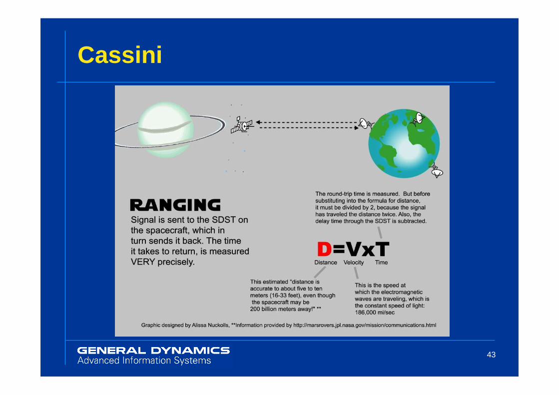
Cassini
CassiniSource: NASA/JPL

42
Cassini
43
Cassini

44
Cassini

45
Mars
Source: NASA/JPL

46
Mars
Source: NASA/JPL

47
Mars
Source: NASA/JPL

48
Mars
Source: NASA/JPL

49
Mars
� Panoramic Camera (Pancam): for determining the mineralogy, texture, and structure of the local terrain
� Miniature Thermal Emission Spectrometer (Mini-TES): for identifying promising rocks and soils for closer examination and for determining the processes that formed Martian rocks. The instrument is designed to look skyward to provide temperature profiles of the Martian atmosphere.
� Mössbauer Spectrometer (MB): for close-up investigations of the mineralogy of iron-bearing rocks and soils.
Source: NASA/JPL

50
Mars
� Alpha Particle X-Ray Spectrometer (APXS): for close-up analysis of the abundances of elements that make up rocks and soils.
� Magnets: for collecting magnetic dust particles. The Mössbauer Spectrometer and the Alpha Particle X-ray Spectrometer are designed to analyze the particles collected and help determine the ratio of magnetic particles to non-magnetic particles. They can also analyze the composition of magnetic minerals in airborne dust and rocks that have been ground by the Rock Abrasion Tool.
� Microscopic Imager (MI): for obtaining close-up, high-resolution images of rocks and soils.
� Rock Abrasion Tool (RAT): for removing dusty and weathered rock surfaces and exposing fresh material for examination by instruments onboard.
Source: NASA/JPL

51
Future of Space Communications
� Laser technology� Currently used in some communications � Advantages include extremely fast speed� Disadvantages include attenuation
� New and improved modulation techniques� Improved efficiency� Less power� Sub-space communications?

52
Conclusion
� Why Do We Explore?
� From the time of our birth, humans have felt a primordial urge to explore -- to blaze new trails, map new lands, and answer profound questions about ourselves and our universe.

54
Q&A


![DOI: 10.1109/ICUWB.2015.7324530, 2015 IEEE. The article ... · ahertz waves. The next generation WLAN standard, IEEE 802.11ad, is designed for 60-GHz band [1]. Much shorter Fig. 1:](https://img.pdfslide.net/doc/110x75/5ec9de30bb8ca67fb4465983/doi-101109icuwb20157324530-2015-ieee-the-article-ahertz-waves-the-next.jpg)