Embed Size (px)
Citation preview
Fro
m K
now
led
ge G
en
era
tio
n T
o S
cie
nce-b
ase
d I
nn
ovati
on
Clara Gouveia ( [email protected] )João Peças Lopes ([email protected])
Power Systems Unit - INESC TECEPFL Lausanne| April 30, 2014
Research and Technological Development | Technology Transfer and Valorisation | Advanced Training | ConsultingPre-incubation of Technology-based Companies
IEEE Workshop Microgrids
A Test Bed in a Laboratory Environment to Validate Islanding and Black Start Solutions for Microgrids
Outline
IEEE Workshop Microgrids: Evolution and Integration in modern power system2
1. MG as smart distribution cell
2. Smart Grids and EVs Laboratory
a) Main Objectives
b) Infrastructures
c) Control Functionalities
d) Experimental Tests
e) Conclusions
f) Future Work
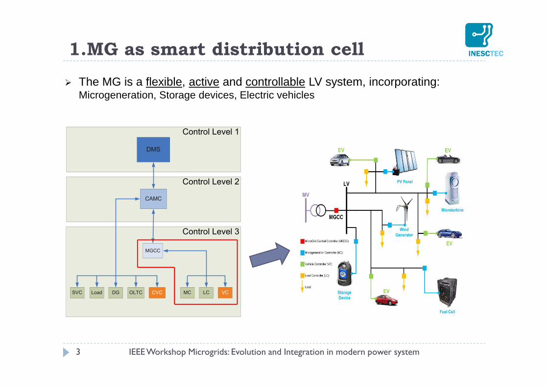
The MG is a flexible, active and controllable LV system, incorporating: Microgeneration, Storage devices, Electric vehicles
3
1.MG as smart distribution cell
DMS
CAMC
LC
MGCC
Control Level 1
Control Level 2
Control Level 3
MCLoadSVC OLTCDG CVC VC
IEEE Workshop Microgrids: Evolution and Integration in modern power system
IEEE Workshop Microgrids: Evolution and Integration in modern power system 4
Ch
arg
ing
ra
teC
ha
rgin
g r
ate
Power
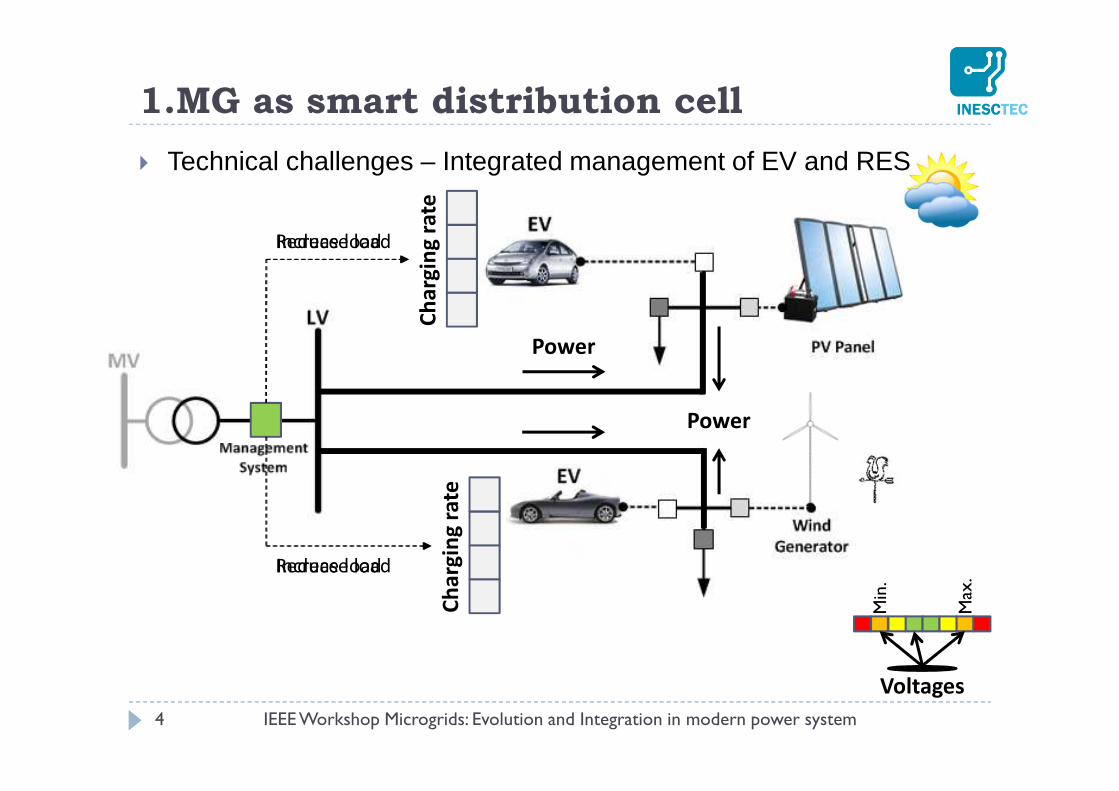
Reduce load
Reduce load
Voltages
Max
.
Min
.
Power
Increase load
Increase load
Technical challenges – Integrated management of EV and RES
1.MG as smart distribution cell
IEEE Workshop Microgrids: Evolution and Integration in modern power system 5
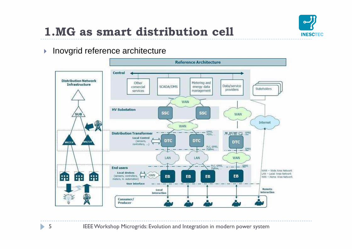
Inovgrid reference architecture
1.MG as smart distribution cell
6
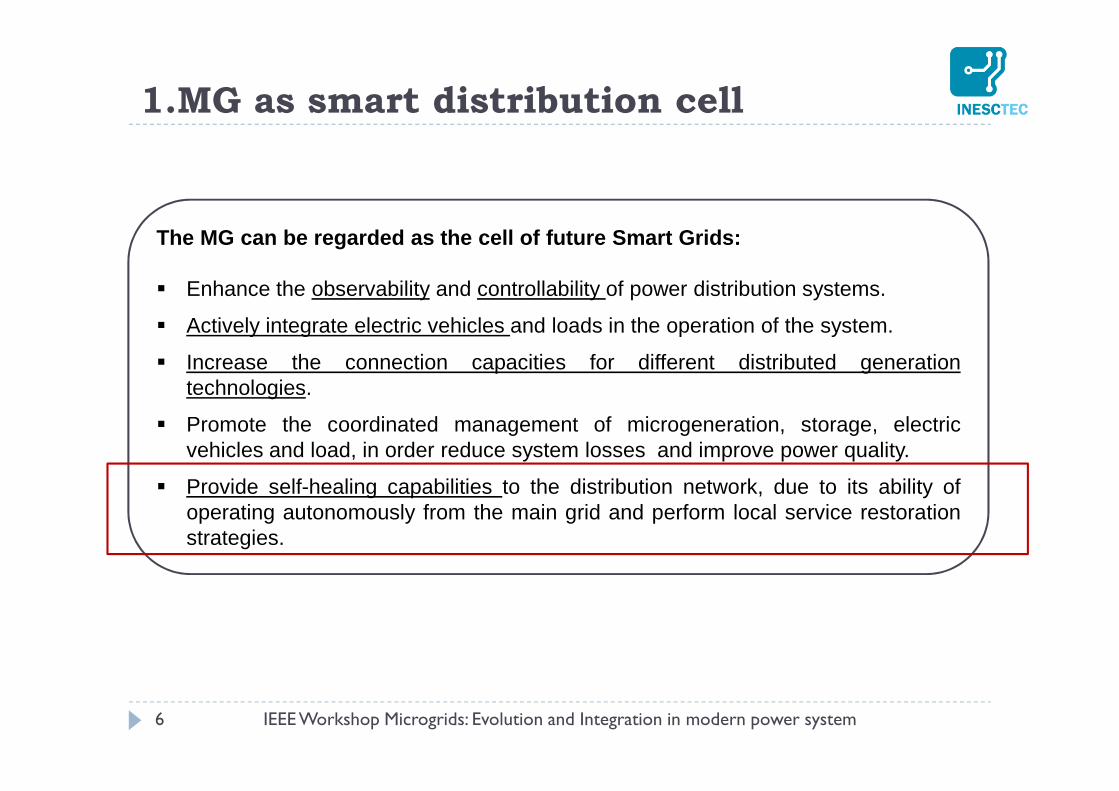
The MG can be regarded as the cell of future Smart Grids:
Enhance the observability and controllability of power distribution systems.
Actively integrate electric vehicles and loads in the operation of the system.
Increase the connection capacities for different distributed generationtechnologies.
Promote the coordinated management of microgeneration, storage, electricvehicles and load, in order reduce system losses and improve power quality.
Provide self-healing capabilities to the distribution network, due to its ability ofoperating autonomously from the main grid and perform local service restorationstrategies.
1.MG as smart distribution cell
IEEE Workshop Microgrids: Evolution and Integration in modern power system
1.MG as smart distribution cell –Emergency Operation
IEEE Workshop Microgrids: Evolution and Integration in modern power system 7
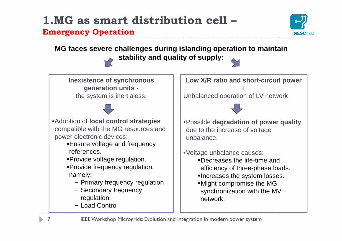
MG faces severe challenges during islanding operati on to maintain stability and quality of supply:
Inexistence of synchronous generation units -
the system is inertialess.
•Adoption of local control strategies compatible with the MG resources and power electronic devices:
Ensure voltage and frequency references.Provide voltage regulation.Provide frequency regulation, namely:
− Primary frequency regulation− Secondary frequency
regulation.− Load Control
Low X/R ratio and short-circuit power+
Unbalanced operation of LV network
•Possible degradation of power quality , due to the increase of voltage unbalance.
•Voltage unbalance causes: Decreases the life-time and efficiency of three-phase loads.Increases the system losses.Might compromise the MG synchronization with the MV network.
2. Smart Grids and Electric Vehicles Laboratorya) Main Objectives
8
Smart Grid Development and Testing
Power Systems
Power Electronics
ICT and cyber
security
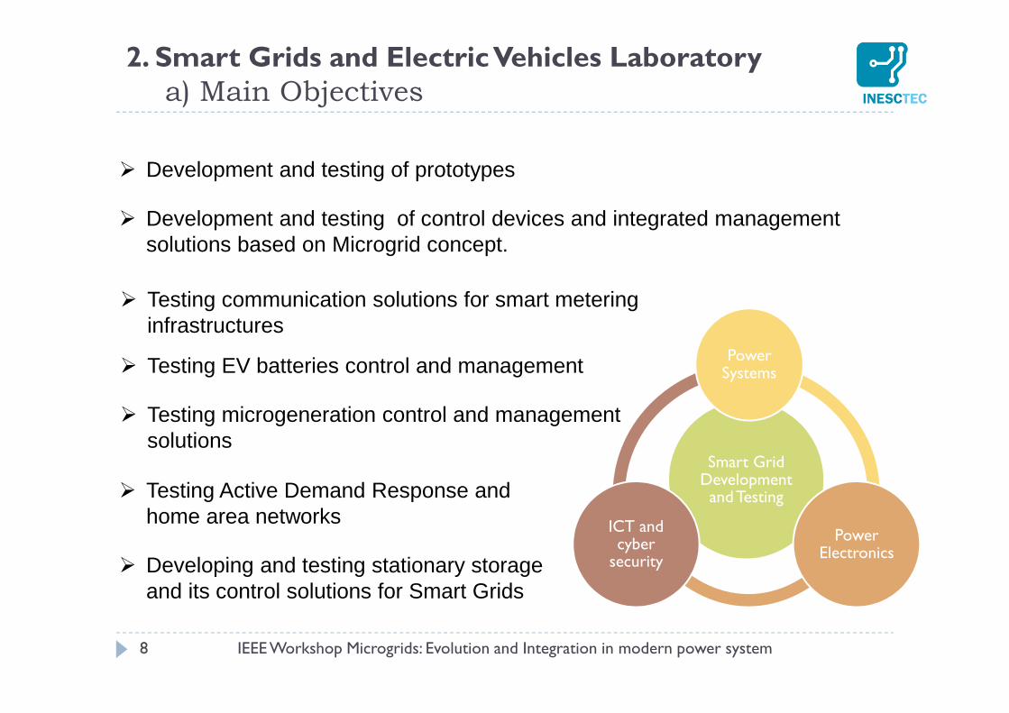
Development and testing of prototypes
Development and testing of control devices and integrated management solutions based on Microgrid concept.
Testing communication solutions for smart metering infrastructures
Testing EV batteries control and management
Testing microgeneration control and management solutions
Testing Active Demand Response and home area networks
Developing and testing stationary storage and its control solutions for Smart Grids
IEEE Workshop Microgrids: Evolution and Integration in modern power system
IEEE Workshop Microgrids: Evolution and Integration in modern power system 9
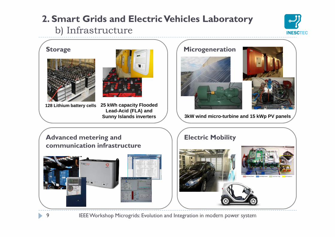
2. Smart Grids and Electric Vehicles Laboratoryb) Infrastructure
Storage
Advanced metering and communication infrastructure
Electric Mobility
128 Lithium battery cells 25 kWh capacity Flooded Lead-Acid (FLA) and
Sunny Islands inverters 3kW wind micro-turbine and 15 kWp PV panels
Microgeneration
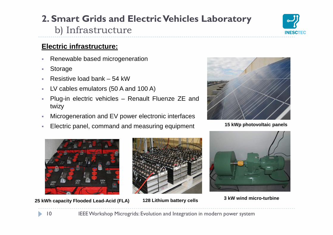
Electric infrastructure:
Renewable based microgeneration
Storage
Resistive load bank – 54 kW
LV cables emulators (50 A and 100 A)
Plug-in electric vehicles – Renault Fluenze ZE andtwizy
Microgeneration and EV power electronic interfaces
Electric panel, command and measuring equipment
10
3 kW wind micro-turbine
15 kWp photovoltaic panels
25 kWh capacity Flooded Lead-Acid (FLA) 128 Lithium battery cells
2. Smart Grids and Electric Vehicles Laboratoryb) Infrastructure
IEEE Workshop Microgrids: Evolution and Integration in modern power system
2. Smart Grids and Electric Vehicles Laboratoryb) Infrastructure
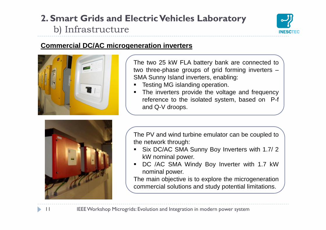
Commercial DC/AC microgeneration inverters
IEEE Workshop Microgrids: Evolution and Integration in modern power system 11
The two 25 kW FLA battery bank are connected totwo three-phase groups of grid forming inverters –SMA Sunny Island inverters, enabling: Testing MG islanding operation. The inverters provide the voltage and frequency
reference to the isolated system, based on P-fand Q-V droops.
The PV and wind turbine emulator can be coupled tothe network through: Six DC/AC SMA Sunny Boy Inverters with 1.7/ 2
kW nominal power. DC /AC SMA Windy Boy Inverter with 1.7 kW
nominal power.The main objective is to explore the microgenerationcommercial solutions and study potential limitations.
10 15 20 25 30 35 40 45 50
5
10
15
20
25
30
35
Time(s)
Act
ive
pow
er (
kW)
Pref
= 18 kW
Pref
= 24 kW
Pref
= 30 kW
12
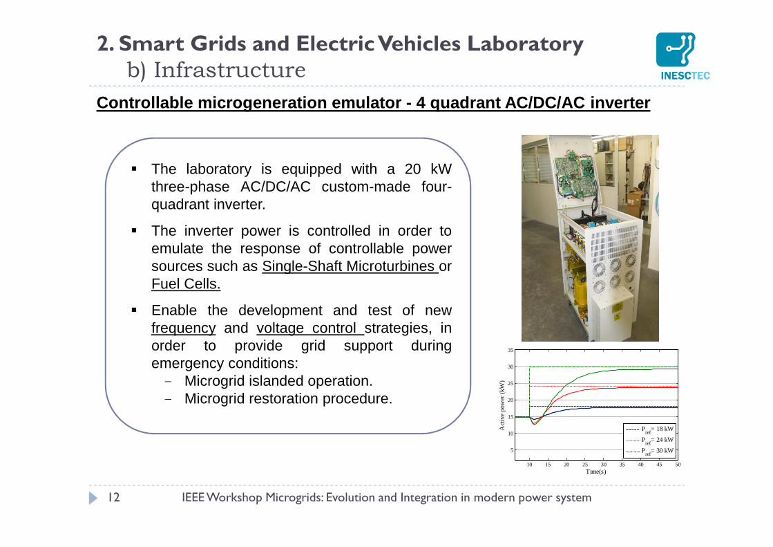
Controllable microgeneration emulator - 4 quadrant A C/DC/AC inverter
The laboratory is equipped with a 20 kWthree-phase AC/DC/AC custom-made four-quadrant inverter.
The inverter power is controlled in order toemulate the response of controllable powersources such as Single-Shaft Microturbines orFuel Cells.
Enable the development and test of newfrequency and voltage control strategies, inorder to provide grid support duringemergency conditions:- Microgrid islanded operation.- Microgrid restoration procedure.
2. Smart Grids and Electric Vehicles Laboratoryb) Infrastructure
IEEE Workshop Microgrids: Evolution and Integration in modern power system
13
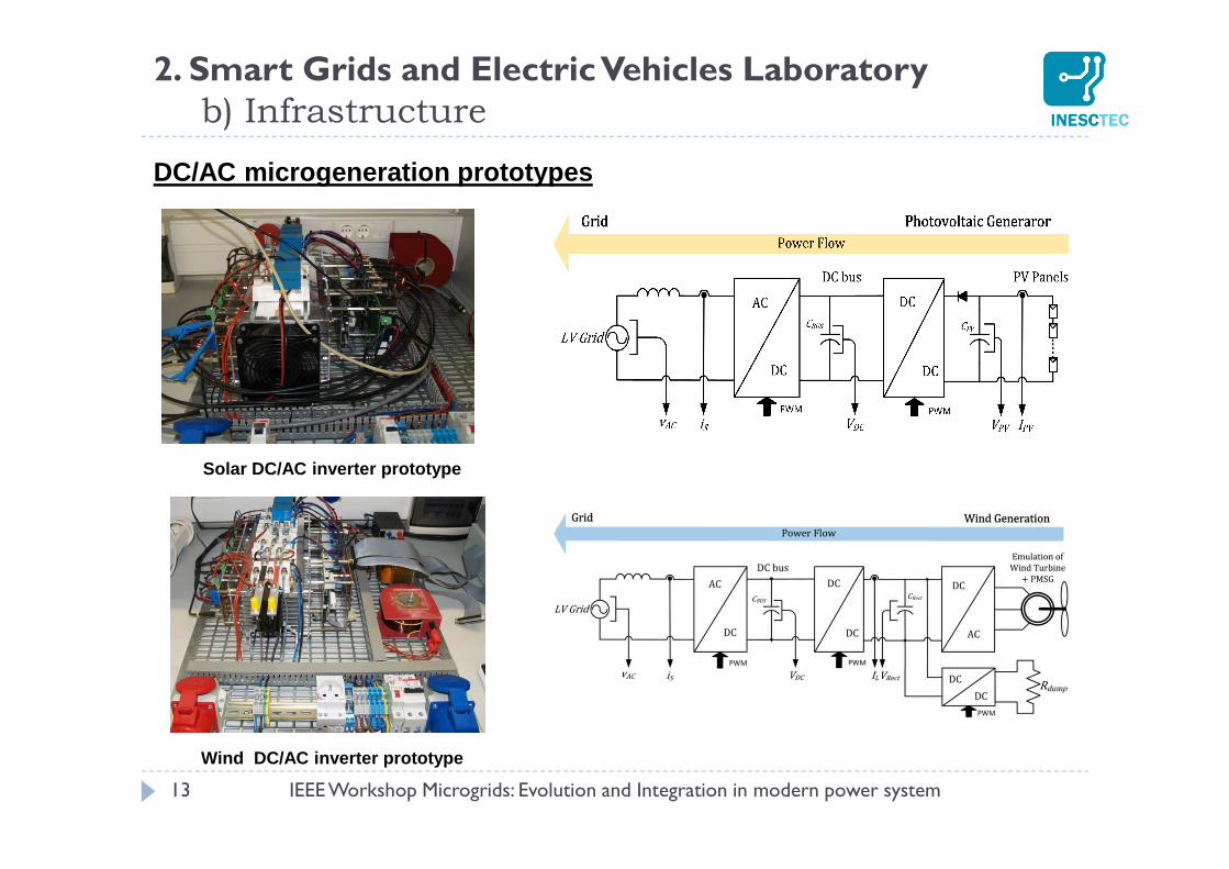
DC/AC microgeneration prototypes
Solar DC/AC inverter prototype
Wind DC/AC inverter prototype
2. Smart Grids and Electric Vehicles Laboratoryb) Infrastructure
IEEE Workshop Microgrids: Evolution and Integration in modern power system
DC/AC microgeneration prototypes
Main functionalities:
Single-phase DC/AC inverters.
Solar inverter with MPPT power adjustment.
Active power control for voltage grid support.
Bidirectional communication with the MGCC.
Possibility of remote control.
Experimental Objectives:
Development and test of new voltage control strategies, in order to providegrid support.
Integration of the new prototypes with the microgrid control andmanagement architecture.
14
2. Smart Grids and Electric Vehicles Laboratoryb) Infrastructure
IEEE Workshop Microgrids: Evolution and Integration in modern power system
15
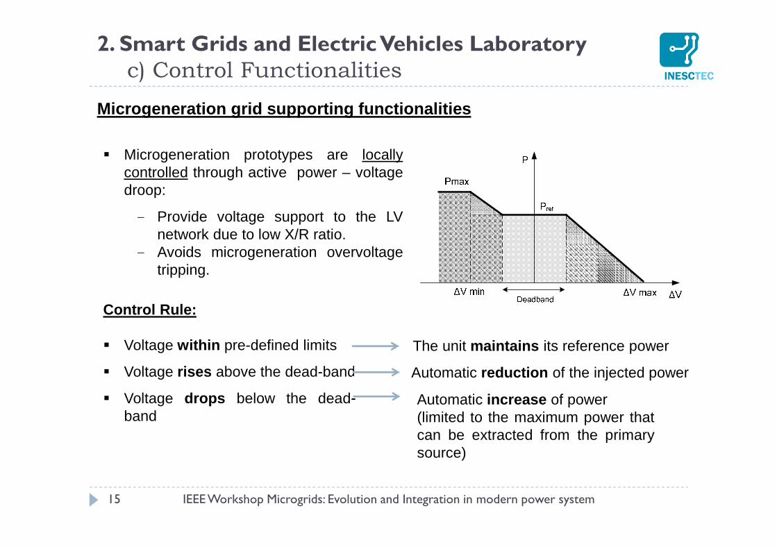
Microgeneration grid supporting functionalities
Microgeneration prototypes are locallycontrolled through active power – voltagedroop:
- Provide voltage support to the LVnetwork due to low X/R ratio.
- Avoids microgeneration overvoltagetripping.
Control Rule:
Voltage within pre-defined limits
Voltage rises above the dead-band
Voltage drops below the dead-band
The unit maintains its reference power
Automatic reduction of the injected power
Automatic increase of power(limited to the maximum power thatcan be extracted from the primarysource)
2. Smart Grids and Electric Vehicles Laboratoryc) Control Functionalities
IEEE Workshop Microgrids: Evolution and Integration in modern power system
16
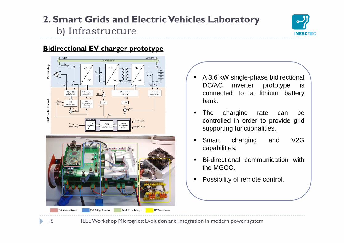
Bidirectional EV charger prototype
A 3.6 kW single-phase bidirectionalDC/AC inverter prototype isconnected to a lithium batterybank.
The charging rate can becontrolled in order to provide gridsupporting functionalities.
Smart charging and V2Gcapabilities.
Bi-directional communication withthe MGCC.
Possibility of remote control.
2. Smart Grids and Electric Vehicles Laboratoryb) Infrastructure
IEEE Workshop Microgrids: Evolution and Integration in modern power system
17
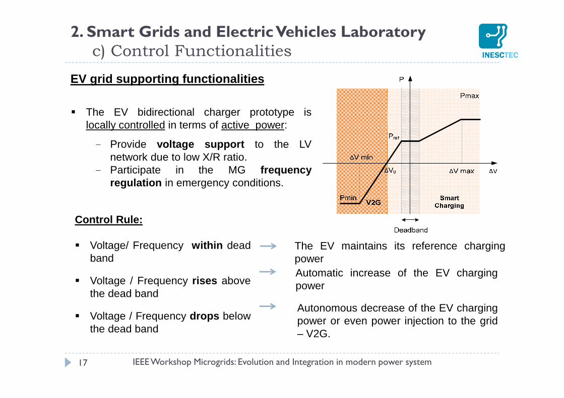
EV grid supporting functionalities
The EV bidirectional charger prototype islocally controlled in terms of active power:
- Provide voltage support to the LVnetwork due to low X/R ratio.
- Participate in the MG frequencyregulation in emergency conditions.
Control Rule:
Voltage/ Frequency within deadband
Voltage / Frequency rises abovethe dead band
Voltage / Frequency drops belowthe dead band
The EV maintains its reference chargingpowerAutomatic increase of the EV chargingpower
Autonomous decrease of the EV chargingpower or even power injection to the grid– V2G.
2. Smart Grids and Electric Vehicles Laboratoryc) Control Functionalities
IEEE Workshop Microgrids: Evolution and Integration in modern power system
18
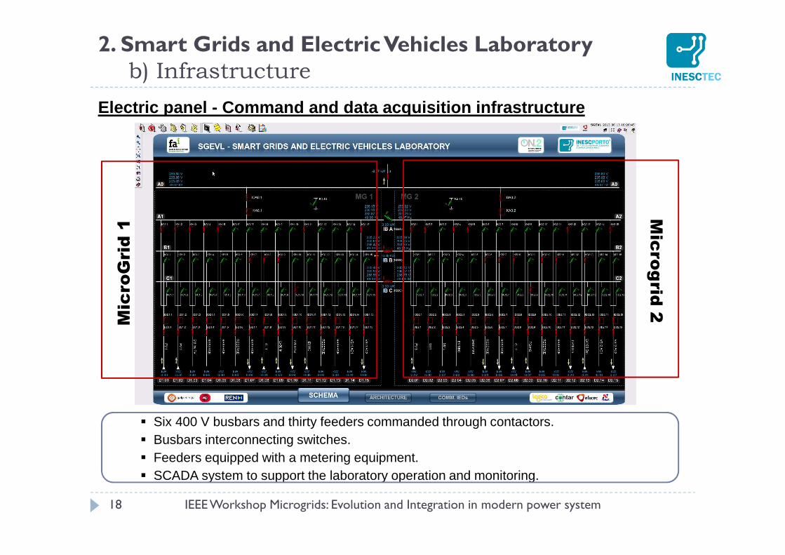
Electric panel - Command and data acquisition infras tructure
Six 400 V busbars and thirty feeders commanded through contactors. Busbars interconnecting switches. Feeders equipped with a metering equipment. SCADA system to support the laboratory operation and monitoring.
2. Smart Grids and Electric Vehicles Laboratoryb) Infrastructure
IEEE Workshop Microgrids: Evolution and Integration in modern power system
Mic
roG
rid
1M
icro
grid
2
19
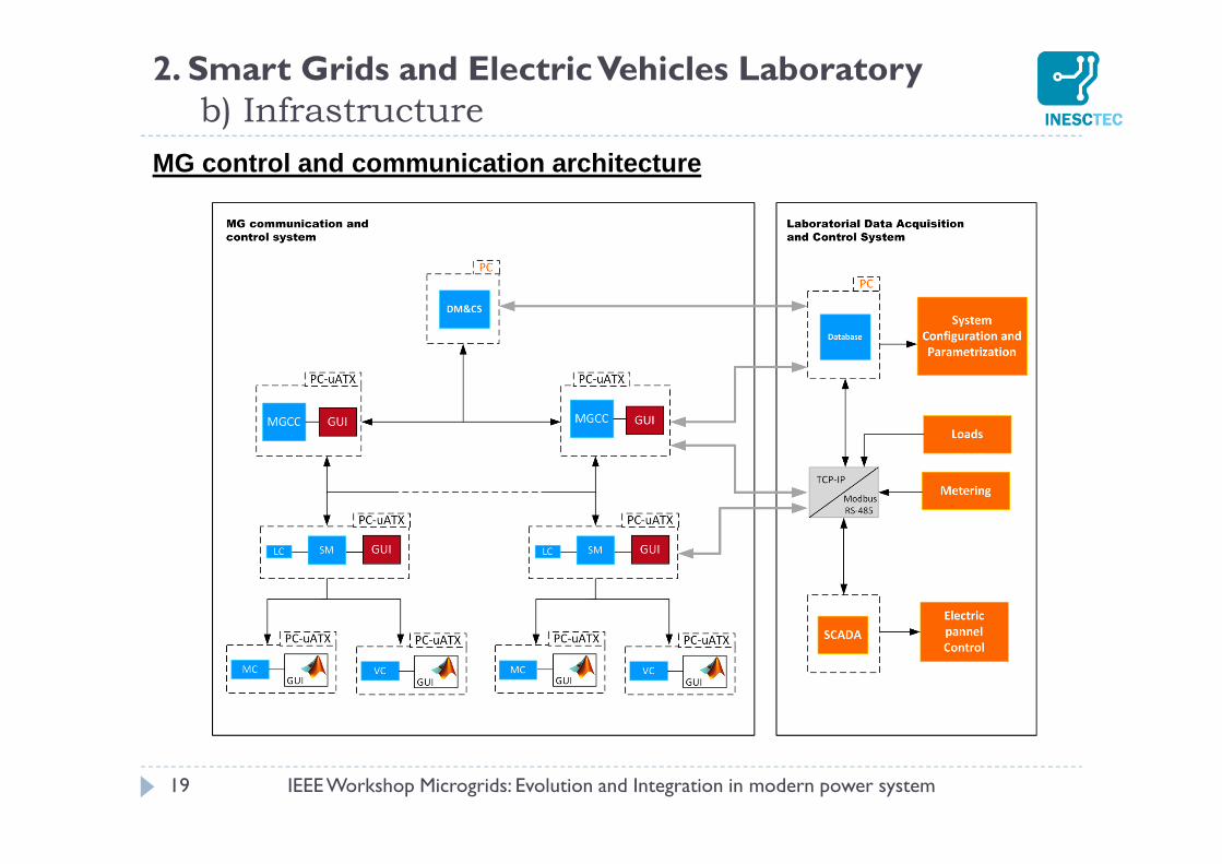
MG control and communication architecture
2. Smart Grids and Electric Vehicles Laboratoryb) Infrastructure
IEEE Workshop Microgrids: Evolution and Integration in modern power system
20
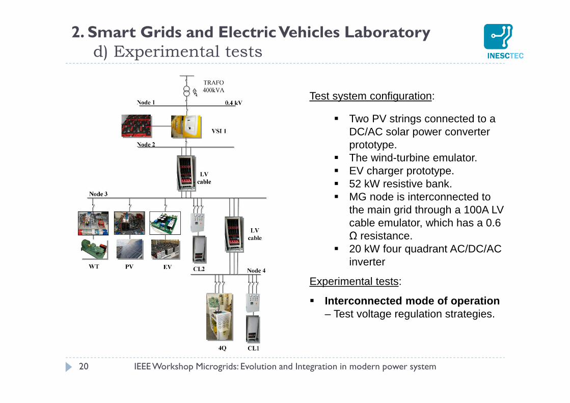
Test system configuration:
Two PV strings connected to a DC/AC solar power converter prototype.
The wind-turbine emulator. EV charger prototype. 52 kW resistive bank. MG node is interconnected to
the main grid through a 100A LV cable emulator, which has a 0.6 Ω resistance.
20 kW four quadrant AC/DC/AC inverter
Experimental tests:
Interconnected mode of operation – Test voltage regulation strategies.
2. Smart Grids and Electric Vehicles Laboratoryd) Experimental tests
IEEE Workshop Microgrids: Evolution and Integration in modern power system
21
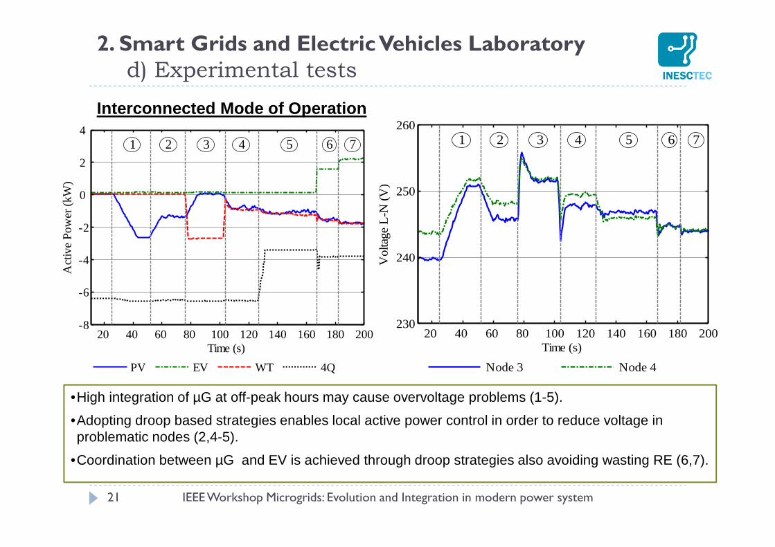
Interconnected Mode of Operation
2. Smart Grids and Electric Vehicles Laboratoryd) Experimental tests
IEEE Workshop Microgrids: Evolution and Integration in modern power system
PV EV WT 4Q
20 40 60 80 100 120 140 160 180 200-8
-6
-4
-2
0
2
4
Act
ive
Pow
er (k
W)
Time (s)
1 2 3 4 5 6 7
Node 3 Node 4
20 40 60 80 100 120 140 160 180 200230
240
250
260
Vol
tage
L-N
(V
)
Time (s)
1 2 3 4 5 6 7
•High integration of µG at off-peak hours may cause overvoltage problems (1-5).
•Adopting droop based strategies enables local active power control in order to reduce voltage in problematic nodes (2,4-5).
•Coordination between µG and EV is achieved through droop strategies also avoiding wasting RE (6,7).
22
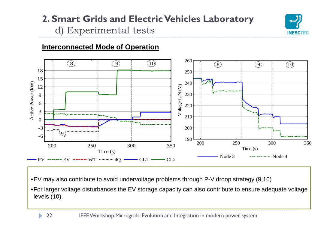
Interconnected Mode of Operation
2. Smart Grids and Electric Vehicles Laboratoryd) Experimental tests
IEEE Workshop Microgrids: Evolution and Integration in modern power system
Node 3 Node 4
200 250 300 350190
200
210
220
230
240
250
260
Vol
tage
L-N
(V)
Time (s)
8 9 10
PV EV WT 4Q CL1 CL2
200 250 300 350
-6
-3
0
3
6
9
12
15
18
Act
ive
Pow
er (k
W)
Time (s)
8 9 10
•EV may also contribute to avoid undervoltage problems through P-V droop strategy (9,10)
•For larger voltage disturbances the EV storage capacity can also contribute to ensure adequate voltage levels (10).
23
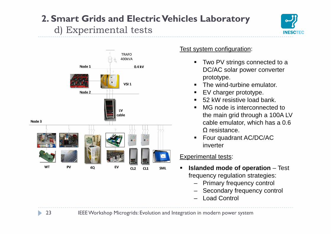
Test system configuration:
Two PV strings connected to a DC/AC solar power converter prototype.
The wind-turbine emulator. EV charger prototype. 52 kW resistive load bank. MG node is interconnected to
the main grid through a 100A LV cable emulator, which has a 0.6 Ω resistance.
Four quadrant AC/DC/AC inverter
Experimental tests:
Islanded mode of operation – Test frequency regulation strategies:
– Primary frequency control– Secondary frequency control– Load Control
2. Smart Grids and Electric Vehicles Laboratoryd) Experimental tests
IEEE Workshop Microgrids: Evolution and Integration in modern power system
24
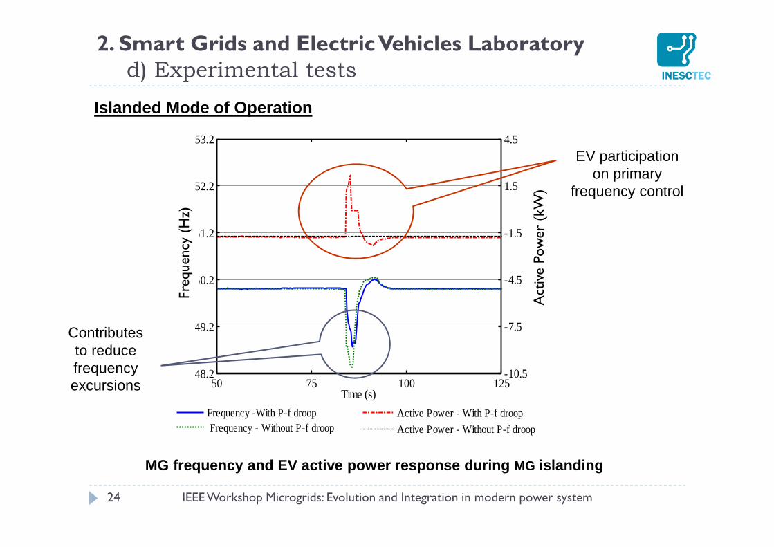
Islanded Mode of Operation
2. Smart Grids and Electric Vehicles Laboratoryd) Experimental tests
MG frequency and EV active power response during MG islanding
IEEE Workshop Microgrids: Evolution and Integration in modern power system
Frequency -With P-f droop Frequency - Without P-f droop
-10.5
-7.5
-4.5
-1.5
1.5
4.5
Act
ive
Pow
er(k
W)
50 75 100 12548.2
49.2
50.2
51.2
52.2
53.2
Time (s)
Freq
uenc
y (H
z)
Active Power - With P-f droop
Active Power - Without P-f droop
Freq
uen
cy (
Hz)
Act
ive
Pow
er (
kW)
EV participation on primary
frequency control
Contributes to reduce frequency excursions
25
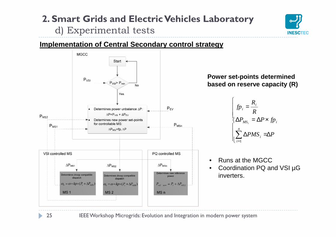
Implementation of Central Secondary control strateg y
2. Smart Grids and Electric Vehicles Laboratoryd) Experimental tests
IEEE Workshop Microgrids: Evolution and Integration in modern power system
• Runs at the MGCC• Coordination PQ and VSI µG
inverters.
∆=∆
×∆=∆
=
∑=
PPMS
fpPPR
Rfp
n
ii
iMS
ii
i
1
Power set-points determined based on reserve capacity (R)
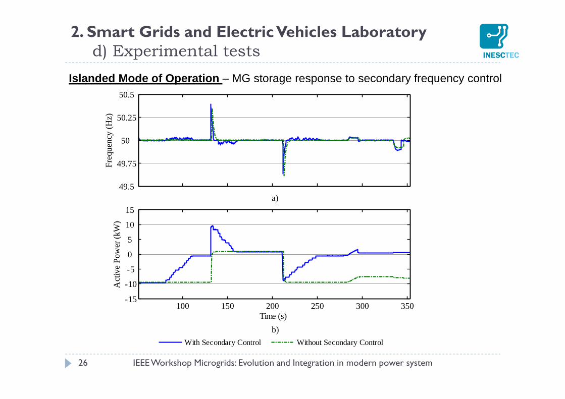
26
Islanded Mode of Operation – MG storage response to secondary frequency control
2. Smart Grids and Electric Vehicles Laboratoryd) Experimental tests
With Secondary Control Without Secondary Control
49.5
49.75
50
50.25
50.5
Fre
quen
cy (
Hz)
100 150 200 250 300 350-15
-10
-5
0
5
10
15
Time (s)
Act
ive
Pow
er (
kW)
a)
b)
IEEE Workshop Microgrids: Evolution and Integration in modern power system
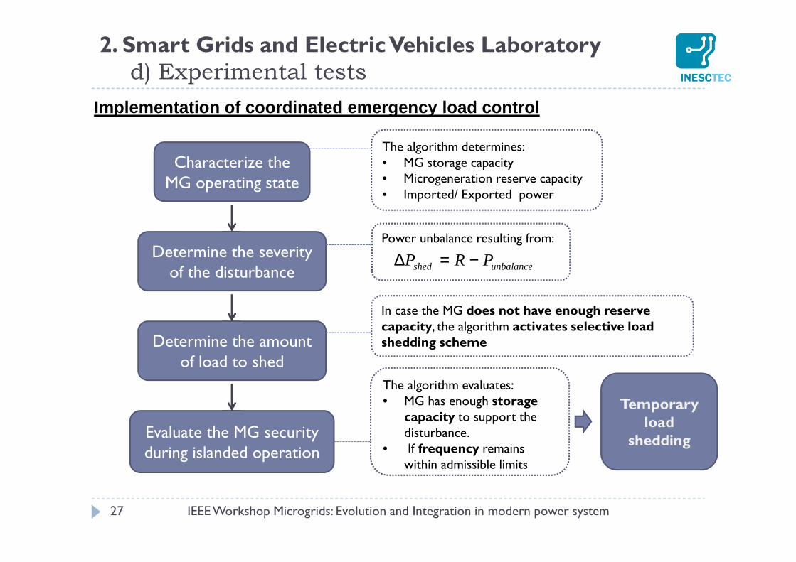
27
Implementation of coordinated emergency load contro l
2. Smart Grids and Electric Vehicles Laboratoryd) Experimental tests
IEEE Workshop Microgrids: Evolution and Integration in modern power system
Characterize the MG operating state
Determine the severity of the disturbance
Determine the amount of load to shed
Evaluate the MG security during islanded operation
The algorithm determines:• MG storage capacity• Microgeneration reserve capacity• Imported/ Exported power
Power unbalance resulting from:
unbalanceshed PRP −=∆
In case the MG does not have enough reserve capacity, the algorithm activates selective load shedding scheme
The algorithm evaluates:• MG has enough storage
capacity to support the disturbance.
• If frequency remains within admissible limits
Temporary load
shedding
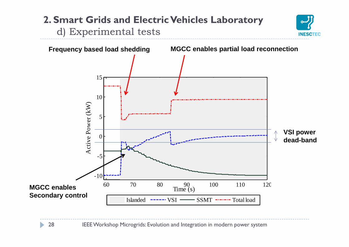
2. Smart Grids and Electric Vehicles Laboratoryd) Experimental tests
28
60 70 80 90 100 110 120
-10
-5
0
5
10
15
Time (s)
Act
ive
Pow
er (
kW)
Islanded VSI SSMT Total load
Frequency based load shedding MGCC enables partial load reconnection
MGCC enables Secondary control
VSI power dead-band
IEEE Workshop Microgrids: Evolution and Integration in modern power system
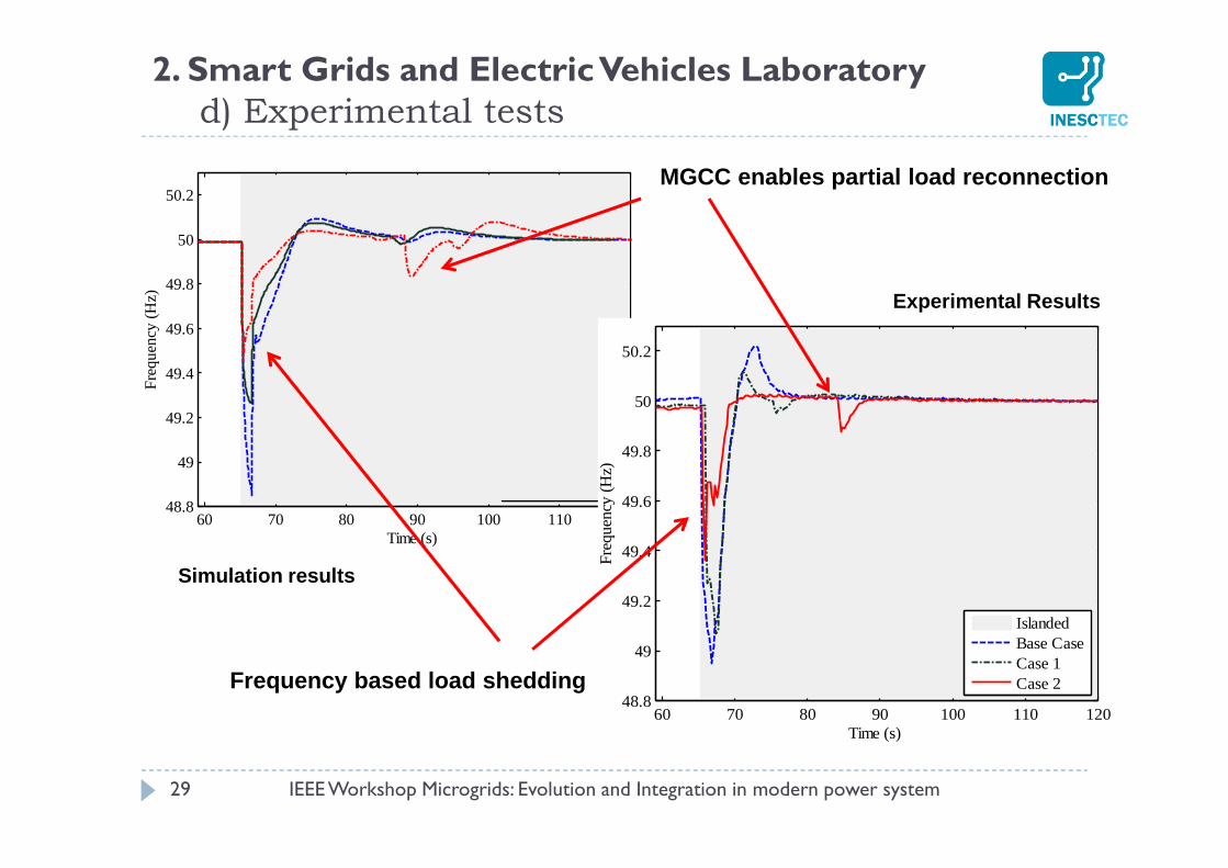
60 70 80 90 100 110 12048.8
49
49.2
49.4
49.6
49.8
50
50.2
Time (s)
Fre
quen
cy (
Hz)
IslandedBase CaseCase 1Case 2
2. Smart Grids and Electric Vehicles Laboratoryd) Experimental tests
29
60 70 80 90 100 110 12048.8
49
49.2
49.4
49.6
49.8
50
50.2
Time (s)
Fre
quen
cy (
Hz)
IslandedBase CaseCase 1Case 2
Simulation results
Experimental Results
Frequency based load shedding
MGCC enables partial load reconnection
IEEE Workshop Microgrids: Evolution and Integration in modern power system
IEEE Workshop Microgrids: Evolution and Integration in modern power system 30
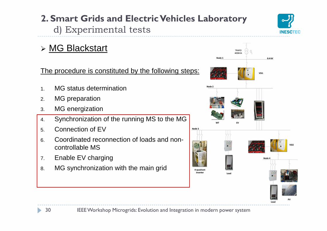
MG Blackstart
The procedure is constituted by the following steps:
1. MG status determination
2. MG preparation
3. MG energization
4. Synchronization of the running MS to the MG
5. Connection of EV
6. Coordinated reconnection of loads and non-controllable MS
7. Enable EV charging
8. MG synchronization with the main grid
2. Smart Grids and Electric Vehicles Laboratoryd) Experimental tests
31
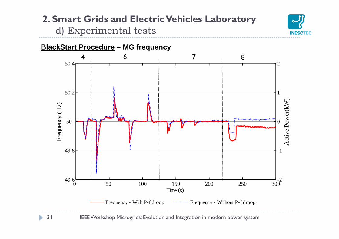
BlackStart Procedure – MG frequency
2. Smart Grids and Electric Vehicles Laboratoryd) Experimental tests
IEEE Workshop Microgrids: Evolution and Integration in modern power system
Frequency - With P-f droop Frequency - Without P-f droop
-2
-1
0
1
2
Act
ive
Pow
er(k
W)
0 50 100 150 200 250 30049.6
49.8
50
50.2
50.4
Time (s)
Fre
quen
cy (
Hz)
4 6 7 8
0 50 100 150 200 250-2
-1.5
-1
-0.5
0
0.5
1
1.5
Time (s)
Act
ive
Pow
er (
kW)
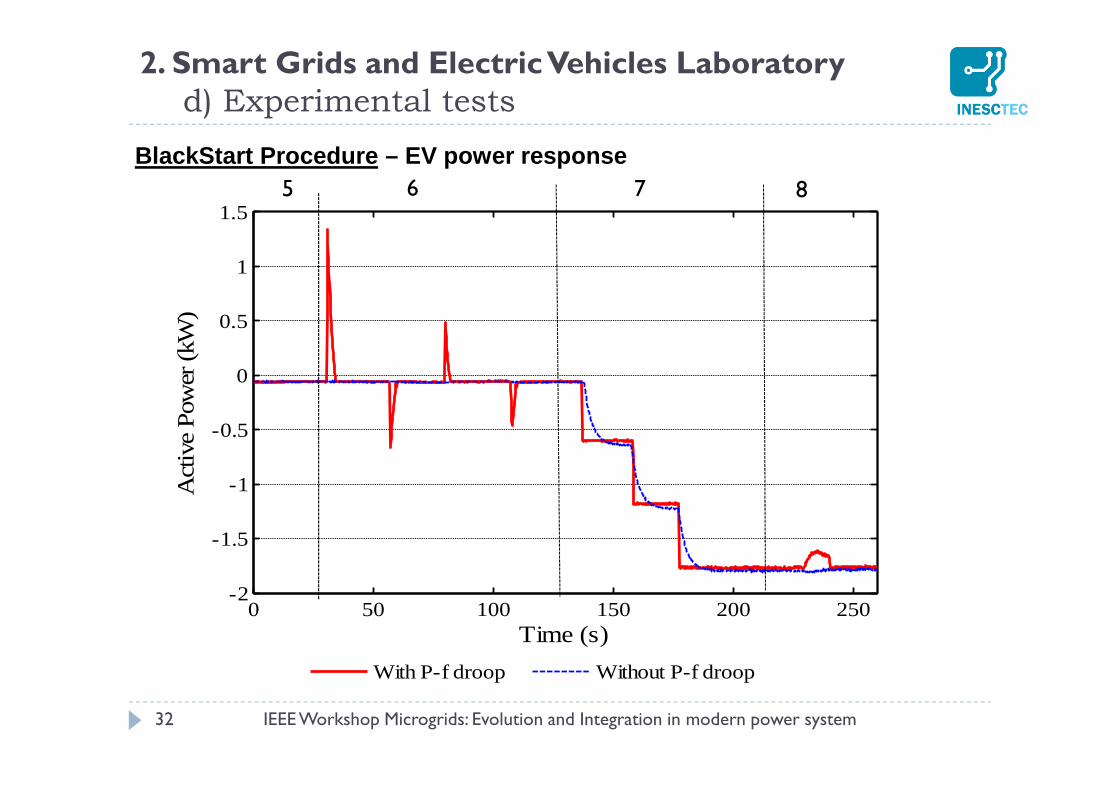
With P-f droop Without P-f droop
32
BlackStart Procedure – EV power response
2. Smart Grids and Electric Vehicles Laboratoryd) Experimental tests
IEEE Workshop Microgrids: Evolution and Integration in modern power system
5 6 7 8
The Smart Grids and EV laboratory plays a key role in theconsolidation of innovative solutions for the development of microgridconcept :
Development of microgeneration and EV grid-coupling inverter prototypesincorporating innovative control strategies.
Local control strategies provide to system operators additional operationresources , in order to deal with the crescent integration of DER resources andEV.
Local control strategies are also complemented by advanced MG controllers to beinstalled at the consumers premises – the Energy Box and at the MV/LVsubstations, the MGCC. The coordination of microgeneration and EV charging increases the system
efficiency, while maintaining voltage within admissible limits. The participation of EV in the MG frequency regulation can reduce the
unbalance between the generation and load within the islanded system. Higher control levels will be responsible for coordinating the devices installed in the
field: Loads, EV, microgeneration and storage.
33
2. Smart Grids and Electric Vehicles Laboratorye ) Conclusions
IEEE Workshop Microgrids: Evolution and Integration in modern power system
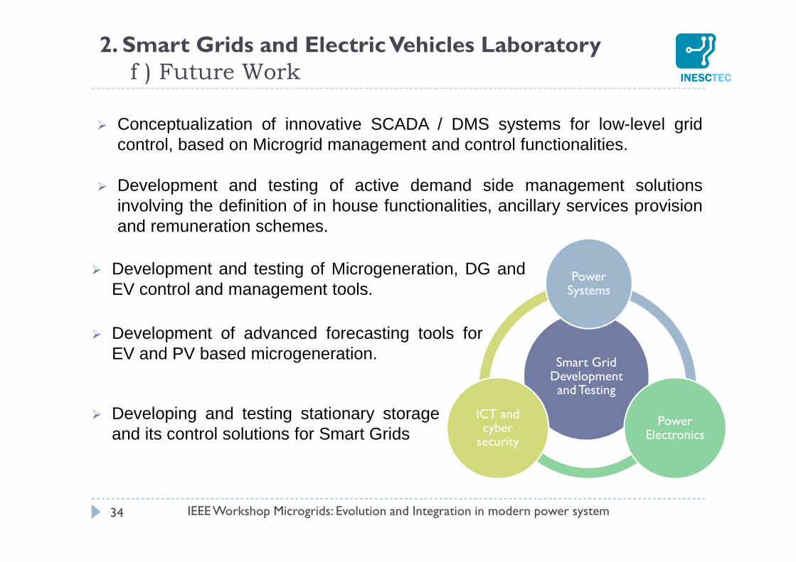
Conceptualization of innovative SCADA / DMS systems for low-level gridcontrol, based on Microgrid management and control functionalities.
Development and testing of active demand side management solutionsinvolving the definition of in house functionalities, ancillary services provisionand remuneration schemes.
34
2. Smart Grids and Electric Vehicles Laboratoryf ) Future Work
IEEE Workshop Microgrids: Evolution and Integration in modern power system
Smart Grid Development and Testing
Power Systems
Power Electronics
ICT and cyber
security
Development and testing of Microgeneration, DG andEV control and management tools.
Development of advanced forecasting tools forEV and PV based microgeneration.
Developing and testing stationary storageand its control solutions for Smart Grids