Embed Size (px)
Citation preview
IEEE/ASME TRANSACTIONS ON MECHATRONICS, VOL. 11, NO. 4, AUGUST 2006 409
Analytical and Experimental Investigation on theMagnetic Field and Torque of a Permanent
Magnet Spherical ActuatorLiang Yan, I-Ming Chen, Senior Member, IEEE, Guilin Yang, Member, IEEE, and Kok-Meng Lee, Fellow, IEEE
Abstract—This paper presents the torque model of a ball-joint-like three-degree-of-freedom (3-DOF) permanent magnet (PM)spherical actuator. This actuator features a ball-shaped rotor withmultiple PM poles and a spherical stator with circumferential air-core coils. An analytical expression of the magnetic field of therotor is obtained based on Laplace’s equation. Based on this ex-pression and properties of air-core stator coils, Lorentz force lawis employed for the study of the relationship between the rotortorque and coil input currents. By using linear superposition, theexpression of the actuator torque in terms of current input to thestator coils can be obtained in a matrix form. The linear expres-sion of the actuator torque will facilitate real-time motion con-trol of the actuator as a servo system. Experimental works arecarried out to measure the actual magnetic field distribution ofthe PM rotor in three-diamensional (3-D) space as well as to mea-sure the actual 3-D motor torque generated by the actuator coils.The measurement results were coincident with analytical study onthe rotor magnetic field distribution and actuator torque expres-sions. The linearity and superposition of the actuator torque werealso verified through the experiments.
Index Terms—Magnetic field, spherical actuator, torque model.
I. INTRODUCTION
CONVENTIONALLY, a three-degree-of-freedom (3-DOF)spherical motion can be realized by several single-axis
actuators connected in parallel or in series. Such a sphericalmotion-generating device inherently has bulky structure, largebacklash, and motion singularities. In applications requiringcompact multi-DOF spherical motion, a spherical actuator witha ball-joint-like device that can produce 2- or 3-DOF rotationalmotion is desired. Unlike single-axis actuators, the torque outputof the spherical actuator has three components. Because alltorque components are dependant on rotor orientation, to obtainactuator torque in terms of input current to the motor coilsbecomes a complicated problem.
Manuscript received October 31, 2005; revised April 2, 2006. Recommendedby Guest Editors K. M. Lee and S. Chiaverini. This work was supported bya collaborative research project under Grant U02-A-O40B for Nanyang Tech-nological University, Singapore Institute of Manufacturing Technology, andGeorgia Institute of Technology.
L. Yan and I-M. Chen are with the School of Mechanical and AerospaceEngineering, Nanyang Technological University, Singapore 637098 (e-mail:[email protected]; [email protected]).
G. Yang is with Mechatronics Group, Singapore Institute of ManufacturingTechnology, Singapore 638075 (e-mail: [email protected]).
K.-M. Lee is with George W. Woodruff School of Mechanical Engineer-ing, Georgia Institute of Technology, Atlanta, GA 30332-0405 USA (e-mail:[email protected]).
Digital Object Identifier 10.1109/TMECH.2006.878545
Williams et al. [1] have designed the first spherical inductionmotor to obtain a variable-speed drive of a single-axis ac motorbased on relative inclination of the rotating shaft. The magneticfield generated by the stator windings induces current on therotor surface, and causes the rotor to incline. Davey et al. [2] de-rived the torque model of this induction motor by integrating theMaxwell stress moment over the spherical rotor surface and pro-posed its use as a robot wrist [3]. The mechanical complexity andthe inherent poor servo characteristics of the spherical inductionmotor led Lee and Kwan [4] to develop a 3-DOF spherical step-per based on the principle of variable reluctance, which takesadvantage of the high coercivity of modern rare-earth perma-nent magnets (PMs). The torque output of a variable-reluctancespherical motor (VRSM) depends on the current inputs as wellas the magnetic reluctance at the air gaps between the rotor andthe stator poles [5]. For any attainable rotor orientation, optimalcurrent inputs [6], [7] can be found to move the rotor to a neigh-borhood with knowledge of reluctance. The torque model ofthis motor is obtained by differentiating coenergy with respectto the angular displacement parameters. In the past decade,several variations of spherical motors with a structure similarto [4] have been studied. Wang et al. [8]–[11] have developedspherical actuators achieving 2-/3-DOF motions. The rotor isa completely magnetized ball. Coils are uniformly mounted onthe stator. The torque models of these spherical actuators wereobtained by using Lorentz force law. Chirikjian and Stein [12]have made a spherical stepper with a PM-pole rotor and a statorwith an array of coils. Difference in the symmetric layout of therotor poles and the stator poles allows stepping motion in threeorientations. Commutation of this stepper motor has been stud-ied to move the rotor. Kahlen et al. [13] developed a sphericalmotor consisting of a rotor sphere with 112 PM poles and anouter stator with 96 stator windings. The poles were arrangedsymmetrically corresponding to lines of longitude and latitudeof a globe. The force/torque produced by the stator winding wascalculated numerically. More recently, Lee et al. [14], [15] havedeveloped a spherical wheel motor (SWM) that offers a meansto control the orientation of its rotating shaft in an open-loopfashion.
This article offers an alternative analytical expression forcomputing the torque output of a spherical actuator that con-sists of a ball-shaped rotor with a full circle of PM polesand a spherical-shell-like stator with multiple layers of air-core coils [16], [17]. This configuration allows more PM polesand coils incorporated to increase the motion resolution andworking range of the actuator. Based on Laplace equation and
1083-4435/$20.00 © 2006 IEEE
410 IEEE/ASME TRANSACTIONS ON MECHATRONICS, VOL. 11, NO. 4, AUGUST 2006
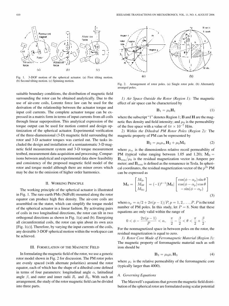
Fig. 1. 3-DOF motion of the spherical actuator. (a) First tilting motion.(b) Second tilting motion. (c) Spinning motion.
suitable boundary conditions, the distribution of magnetic fieldsurrounding the rotor can be obtained analytically. Due to theuse of air-core coils, Lorentz force law can be used for thederivation of the relationship between the actuator torque andinput coil currents. The complete actuator torque can be ex-pressed in a matrix form in terms of input currents from all coilsthrough linear superposition. This analytical expression of thetorque output can be used for motion control and design op-timization of the spherical actuator. Experimental verificationof the three-diamensional (3-D) magnetic field surrounding therotor and 3-D actuator torques was carried out. The tasks in-cluded the design and installation of a semiautomatic 3-D mag-netic field measurement system and 3-D torque measurementtestbed, measurement data acquisition and processing. Compar-isons between analytical and experimental data show feasibilityand consistency of the proposed magnetic field model of therotor and torque model although there are minor errors whichmay be due to the omission of higher order harmonics.
II. WORKING PRINCIPLE
The working principle of the spherical actuator is illustratedin Fig. 1. The rare-earth PMs (NdFeB) mounted along the rotorequator can produce high flux density. The air-core coils areassembled on the stator, which can simplify the torque modelof the spherical actuator in a linear fashion. By activating pairsof coils in two longitudinal directions, the rotor can tilt in twoorthogonal directions as shown in Fig. 1(a) and (b). Energizingall circumferential coils, the rotor can spin about its own axis[Fig. 1(c)]. Therefore, by varying the input currents of the coils,any desirable 3-DOF spherical motion within the workspace canbe achieved.
III. FORMULATION OF THE MAGNETIC FIELD
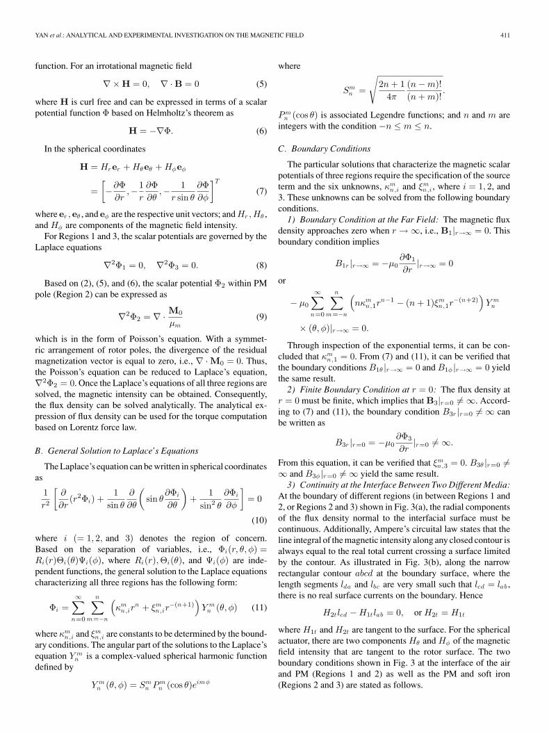
In formulating the magnetic field of the rotor, we use a genericrotor model shown in Fig. 2 for discussion. The PM rotor polesare evenly spaced (with alternate polarities) around the rotorequator, each of which has the shape of a dihedral cone definedin terms of four parameters: longitudinal angle α, latitudinalangle β, and outer and inner radii Rr and Rb . With such anarrangement, the study of the rotor magnetic field can be dividedinto three parts.
Fig. 2. Arrangement of rotor poles. (a) Single rotor pole. (b) Alternatelyarranged poles.
1) Air Space Outside the Rotor (Region 1): The magneticeffect of air space can be characterized by
B1 = µ0H1 (1)
where the subscript “1” denotes Region 1; B and H are the mag-netic flux density and field intensity; and µ0 is the permeabilityof the free space with a value of 4π × 10−7 H/m.
2) Within the Dihedral PM Rotor Poles (Region 2): Themagnetic property of PM can be represented by
B2 = µ0µmH2 + µ0M0 (2)
where µm is the dimensionless relative recoil permeability ofPM (typical value ranging between 1.05 and 1.20); M0 =Brem/µ0 is the residual magnetization vector in Ampere permeter; and Brem is defined as the remanence in Tesla. In spheri-cal coordinates, the residual magnetization vector of the pth PMcan be expressed as
M0 =
M0r
M0θ
M0φ
= (−1)p−1|M0|
cos(φ − αp) sin θ
cos(φ − αp) cos θ− sin(φ − αp)
(3)
where αp = α/2 + 2π(p − 1)/P, p = 1, 2, . . . , P . P is the totalnumber of PM poles. In this study, let P = 8. Note that theseequations are only valid within the range of
0 < φ − 2π(p − 1)P
< α,π
2− β
2< θ <
π
2+
β
2.
For the nonmagnetized space in between poles on the rotor, theresidual magnetization is equal to zero.
3) Rotor Core Made of Ferromagnetic Material (Region 3):The magnetic property of ferromagnetic material such as softiron should be
B3 = µ0µrH3 (4)
where µr is the relative permeability of the ferromagnetic core(typically larger than 4000).
A. Governing Equations
The Maxwell’s equations that govern the magnetic field distri-bution of the spherical rotor are formulated using scalar potential
YAN et al.: ANALYTICAL AND EXPERIMENTAL INVESTIGATION ON THE MAGNETIC FIELD 411
function. For an irrotational magnetic field
∇× H = 0, ∇ · B = 0 (5)
where H is curl free and can be expressed in terms of a scalarpotential function Φ based on Helmholtz’s theorem as
H = −∇Φ. (6)
In the spherical coordinates
H = Hrer + Hθeθ + Hφeφ
=[−∂Φ
∂r,−1
r
∂Φ∂θ
,− 1r sin θ
∂Φ∂φ
]T
(7)
where er , eθ , and eφ are the respective unit vectors; and Hr ,Hθ ,and Hφ are components of the magnetic field intensity.
For Regions 1 and 3, the scalar potentials are governed by theLaplace equations
∇2Φ1 = 0, ∇2Φ3 = 0. (8)
Based on (2), (5), and (6), the scalar potential Φ2 within PMpole (Region 2) can be expressed as
∇2Φ2 = ∇ · M0
µm(9)
which is in the form of Poisson’s equation. With a symmet-ric arrangement of rotor poles, the divergence of the residualmagnetization vector is equal to zero, i.e., ∇ · M0 = 0. Thus,the Poisson’s equation can be reduced to Laplace’s equation,∇2Φ2 = 0. Once the Laplace’s equations of all three regions aresolved, the magnetic intensity can be obtained. Consequently,the flux density can be solved analytically. The analytical ex-pression of flux density can be used for the torque computationbased on Lorentz force law.
B. General Solution to Laplace’s Equations
The Laplace’s equation can be written in spherical coordinatesas
1r2
[∂
∂r(r2Φi) +
1sin θ
∂
∂θ
(sin θ
∂Φi
∂θ
)+
1sin2 θ
∂Φi
∂φ
]= 0
(10)
where i (= 1, 2, and 3) denotes the region of concern.Based on the separation of variables, i.e., Φi(r, θ, φ) =Ri(r)Θi(θ)Ψi(φ), where Ri(r),Θi(θ), and Ψi(φ) are inde-pendent functions, the general solution to the Laplace equationscharacterizing all three regions has the following form:
Φi =∞∑
n=0
n∑m=−n
(κm
n,irn + ξm
n,ir−(n+1)
)Y m
n (θ, φ) (11)
where κmn,i and ξm
n,i are constants to be determined by the bound-ary conditions. The angular part of the solutions to the Laplace’sequation Y m
n is a complex-valued spherical harmonic functiondefined by
Y mn (θ, φ) = Sm
n Pmn (cos θ)eimφ
where
Smn =
√2n + 1
4π
(n − m)!(n + m)!
.
Pmn (cos θ) is associated Legendre functions; and n and m are
integers with the condition −n ≤ m ≤ n.
C. Boundary Conditions
The particular solutions that characterize the magnetic scalarpotentials of three regions require the specification of the sourceterm and the six unknowns, κm
n,i and ξmn,i , where i = 1, 2, and
3. These unknowns can be solved from the following boundaryconditions.
1) Boundary Condition at the Far Field: The magnetic fluxdensity approaches zero when r → ∞, i.e., B1|r→∞ = 0. Thisboundary condition implies
B1r |r→∞ = −µ0∂Φ1
∂r|r→∞ = 0
or
− µ0
∞∑n=0
n∑m=−n
(nκm
n,1rn−1 − (n + 1)ξm
n,1r−(n+2)
)Y m
n
× (θ, φ)|r→∞ = 0.
Through inspection of the exponential terms, it can be con-cluded that κm
n,1 = 0. From (7) and (11), it can be verified thatthe boundary conditions B1θ |r→∞ = 0 and B1φ |r→∞ = 0 yieldthe same result.
2) Finite Boundary Condition at r = 0: The flux density atr = 0 must be finite, which implies that B3|r=0 �= ∞. Accord-ing to (7) and (11), the boundary condition B3r |r=0 �= ∞ canbe written as
B3r |r=0 = −µ0∂Φ3
∂r|r=0 �= ∞.
From this equation, it can be verified that ξmn,3 = 0. B3θ |r=0 �=
∞ and B3φ |r=0 �= ∞ yield the same result.3) Continuity at the Interface Between Two Different Media:
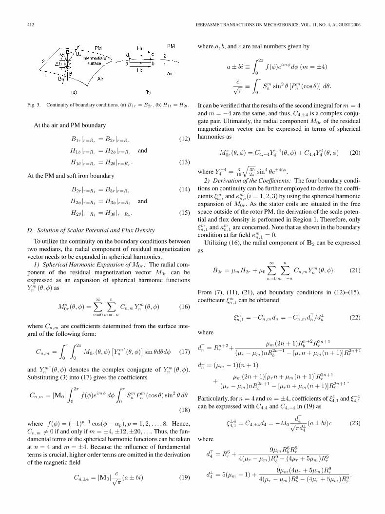
At the boundary of different regions (in between Regions 1 and2, or Regions 2 and 3) shown in Fig. 3(a), the radial componentsof the flux density normal to the interfacial surface must becontinuous. Additionally, Ampere’s circuital law states that theline integral of the magnetic intensity along any closed contour isalways equal to the real total current crossing a surface limitedby the contour. As illustrated in Fig. 3(b), along the narrowrectangular contour abcd at the boundary surface, where thelength segments lda and lbc are very small such that lcd = lab ,there is no real surface currents on the boundary. Hence
H2t lcd − H1t lab = 0, or H2t = H1t
where H1t and H2t are tangent to the surface. For the sphericalactuator, there are two components Hθ and Hφ of the magneticfield intensity that are tangent to the rotor surface. The twoboundary conditions shown in Fig. 3 at the interface of the airand PM (Regions 1 and 2) as well as the PM and soft iron(Regions 2 and 3) are stated as follows.
412 IEEE/ASME TRANSACTIONS ON MECHATRONICS, VOL. 11, NO. 4, AUGUST 2006
Fig. 3. Continuity of boundary conditions. (a) B1r = B2r . (b) H1t = H2t .
At the air and PM boundary
B1r |r=Rr= B2r |r=Rr
(12)
H1φ |r=Rr= H2φ |r=Rr
and
H1θ |r=Rr= H2θ |r=Rr
. (13)
At the PM and soft iron boundary
B2r |r=Rb= B3r |r=Rb
(14)
H2φ |r=Rb= H3φ |r=Rb
and
H2θ |r=Rb= H3θ |r=Rb
. (15)
D. Solution of Scalar Potential and Flux Density
To utilize the continuity on the boundary conditions betweentwo medians, the radial component of residual magnetizationvector needs to be expanded in spherical harmonics.
1) Spherical Harmonic Expansion of M0r : The radial com-ponent of the residual magnetization vector M0r can beexpressed as an expansion of spherical harmonic functionsY m
n (θ, φ) as
Ms0r (θ, φ) =
∞∑n=0
n∑m=−n
Cn,m Y mn (θ, φ) (16)
where Cn,m are coefficients determined from the surface inte-gral of the following form:
Cn,m =∫ π
0
∫ 2π
0
M0r (θ, φ)[Y m ∗
n (θ, φ)]sin θdθdφ (17)
and Y m ∗n (θ, φ) denotes the complex conjugate of Y m
n (θ, φ).Substituting (3) into (17) gives the coefficients
Cn,m = |M0|∫ 2π
0
f(φ)eimφ dφ
∫ π
0
Smn Pm
n (cos θ) sin2 θ dθ
(18)
where f(φ) = (−1)p−1 cos(φ − αp), p = 1, 2, . . . , 8. Hence,Cn,m �= 0 if and only if m = ±4,±12,±20, . . .. Thus, the fun-damental terms of the spherical harmonic functions can be takenat n = 4 and m = ±4. Because the influence of fundamentalterms is crucial, higher order terms are omitted in the derivationof the magnetic field
C4,±4 = |M0|c√π
(a ± bi) (19)
where a, b, and c are real numbers given by
a ± bi ≡∫ 2π
0
f(φ)eimφdφ (m = ±4)
c√π
≡∫ π
0
Smn sin2 θ [Pm
n (cos θ)] dθ.
It can be verified that the results of the second integral for m = 4and m = −4 are the same, and thus, C4,±4 is a complex conju-gate pair. Ultimately, the radial component M0r of the residualmagnetization vector can be expressed in terms of sphericalharmonics as
Ms0r (θ, φ) = C4,−4Y
−44 (θ, φ) + C4,4Y
44 (θ, φ) (20)
where Y ±44 = 3
16
√352π sin4 θe±4iφ .
2) Derivation of the Coefficients: The four boundary condi-tions on continuity can be further employed to derive the coeffi-cients ξm
n,i and κmn,i(i = 1, 2, 3) by using the spherical harmonic
expansion of M0r . As the stator coils are situated in the freespace outside of the rotor PM, the derivation of the scale poten-tial and flux density is performed in Region 1. Therefore, onlyξmn,1 and κm
n,1 are concerned. Note that as shown in the boundarycondition at far field κm
n,1 = 0.Utilizing (16), the radial component of B2 can be expressed
as
B2r = µm H2r + µ0
∞∑n=0
n∑m=−n
Cn,m Y mn (θ, φ). (21)
From (7), (11), (21), and boundary conditions in (12)–(15),coefficient ξm
n,1 can be obtained
ξmn,1 = −Cn,m dn = −Cn,m dn /d⊥n (22)
where
dn = Rn+2r +
µm (2n + 1)Rn+2b R2n+1
r
(µr − µm )nR2n+1b − [µrn + µm (n + 1)]R2n+1
r
d⊥n = (µm − 1)(n + 1)
+µm (2n + 1)[µrn + µm (n + 1)]R2n+1
r
(µr − µm )nR2n+1b − [µrn + µm (n + 1)]R2n+1
r
.
Particularly, for n = 4 and m = ±4, coefficients of ξ44,1 and ξ−4
4,1
can be expressed with C4,4 and C4,−4 in (19) as
ξ±44,1 = C4,±4d4 = −M0
d4√πd⊥4
(a ± bi)c (23)
where
d4 = R6r +
9µm R6b R
9r
4(µr − µm )R9b − (4µr + 5µm )R9
r
d⊥4 = 5(µm − 1) +9µm (4µr + 5µm )R9
r
4(µr − µm )R9b − (4µr + 5µm )R9
r
.
YAN et al.: ANALYTICAL AND EXPERIMENTAL INVESTIGATION ON THE MAGNETIC FIELD 413
Fig. 4. Force activated by three components of the flux density (P is a planetangential to the sphere at point O; dl, B1θ , B1φ are vectors on plane P; B1r
is normal to plane P. (a) r-direction. (b) θ-direction. (c) φ-direction.
3) Solution of Magnetic Scalar Potential and Flux Density:Substituting ξ4
4,1 and ξ−44,1 into (11) and discarding the higher
order harmonic terms result in
Φ1 = M03cd48πd⊥4
√352
r−5 sin4 θ(a cos 4φ − b sin 4φ). (24)
Using (1) and (7), the flux density in Region 1 can be obtain as B1r
B1θ
B1φ
=
3µ0M0cd4
8πd⊥4
√352
r−6sθ3
5sθ(a c4φ − b s4φ)
4cθ(b s4φ − a c4φ)4(a s4φ + b c4φ)
(25)
where sθ, cθ, s4φ, and c4φ denote sin θ, cos θ, sin 4φ, andcos 4φ, respectively. The direction of the force generated byeach component of the flux density can be determined as shownin Fig. 4. The differential length dl of the wire is tangent to thespherical surface at point O. Note that only B1r can producea torque to change the rotor orientation. B1θ and B1φ do notproduce torque on the rotor because the action lines of magneticforces generated by B1φ and B1θ pass through the rotor center.Consequently, the following discussion focuses on the radialcomponent B1r .
IV. FORMULATION OF THE TORQUE MODEL
Because the stator poles are air-core coils, Lorentz force lawcan be employed for obtaining the torque model of this PMspherical actuator.
A. Approximation of Coil Geometry
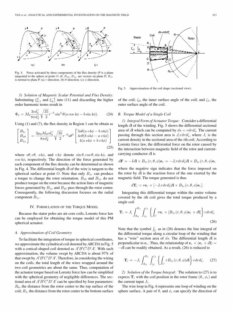
To facilitate the integration of torque in spherical coordinates,we approximate the cylindrical coil denoted by ABCDA in Fig. 5with a conical-shaped coil denoted as A′B′C ′D′A′. With suchapproximation, the volume swept by ABCDA is about 97% ofthat swept by A′B′C ′D′A′. Therefore, in considering the wiringon the coils, the total length of the wires wrapped around thetwo coil geometries are about the same. Thus, computation ofthe actuator torque based on Lorentz force law can be simplifiedwith the spherical geometry of negligible differences. The sec-tional area of A′B′C ′D′A′ can be specified by four parameters:R0, the distance from the rotor center to the top surface of thecoil; R1, the distance from the rotor center to the bottom surface
Fig. 5. Approximation of the coil shape (sectional view).
of the coil; ζ0, the inner surface angle of the coil; and ζ1, theouter surface angle of the coil.
B. Torque Model of a Single Coil
1) Integral Form of Actuator Torque: Consider a differentiallength dl of the winding. Fig. 5 shows the differential sectionalarea of dl which can be computed by ds = rdrdζ. The currentpassing through this section area is Jirdrdζ, where Ji is thecurrent density in the sectional area of the ith coil. According toLorentz force law, the differential force on the rotor caused bythe interaction between magnetic field of the rotor and current-carrying conductor dl is
dF = −Idl × B1r (r, θ, φ)er = −Jirdrdζdl × B1r (r, θ, φ)er
where the negative sign indicates that the force imposed onthe rotor by dl is the reaction force of the one exerted by themagnetic field. The torque generated is thus
dTi = rer × [−Jirdrdζdl × B1r (r, θ, φ)er ].
Integrating this differential torque within the entire volumecovered by the ith coil gives the total torque produced by asingle coil
Ti = Ji
∫ R1
R0
∫ ζ1
ζ0
{∫C
rer × [B1r (r, θ, φ)er × dl]}
rdrdζ.
(26)
Note that the symbol∫
C as in (26) denotes the line integral ofthe differential torque along a circular loop of the winding thathas a “wire” section area of ds. The differential length dl isperpendicular to er . Thus, the relationship of er × (er × dl) =−dl can be readily obtained. As a result, (26) is reduced to
Ti = −Ji
∫ R1
R0
∫ ζ1
ζ0
{∫C
rB1r (r, θ, φ)dl}
rdrdζ. (27)
2) Solution of the Torque Integral: The solution to (27) is toexpress Ti with the coil position in the rotor frame (θi, φi) andthe current input Ji .
The wire loop in Fig. 6 represents one loop of winding on thesphere surface. A pair of θi and φi can specify the direction of
414 IEEE/ASME TRANSACTIONS ON MECHATRONICS, VOL. 11, NO. 4, AUGUST 2006
Fig. 6. One loop of wire on the sphere surface.
the ith coil axis in the rotor frame. Correspondingly, eθi and eφi
represent the unit vectors in θi and φi directions. The segmentdl can be expressed as
dl = r sin ζdψ(sin ψeθi − cos ψeφi). (28)
Substituting B1r in (25) and (28) into (27), and using the relationbetween Cartesian coordinates and ζ, ψ, θi , φi , the expressionof Ti can be finally obtained as
Ti = [Txi Tyi Tzi ]T = Tcf(θi, φi)Ji (29)
where Tc =√
352
15µ0M0cd416π (R−2
0 − R−21 ), and f(θi, φi) =
[fx(θi, φi) fy (θi, φi) fz (θi, φi)]T is a 3× 1 vector completelydetermined by the coils position in the rotor frame [see [18] forthe expression of f(θi, φi)].
C. Torque Model of the Full Set of Coils
Equation (29) represents the torque of a single coil. WithN coils on the stator, there are N torque equations like (29).Arranging all N equations in a matrix form, the torque modelof the spherical actuator with a complete set of coils can beobtained
T=Tc
fx(θ1, φ1) fx(θ2, φ2) · · · fx(θN , φN )
fy (θ1, φ1) fy (θ2, φ2) · · · fy (θN , φN )fz (θ1, φ1) fz (θ2, φ2) · · · fz (θN , φN )
J1
J2...
JN
= TcQJ (30)
where J = [J1 J2 · · · JN ]T represents currents passing throughN coils, and Q is defined to be the torque matrix
Q =
fx(θ1, φ1) fx(θ2, φ2) · · · fx(θN , φN )
fy (θ1, φ1) fy (θ2, φ2) · · · fy (θN , φN )fz (θ1, φ1) fz (θ2, φ2) · · · fz (θN , φN )
.
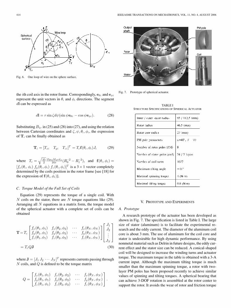
Fig. 7. Prototype of spherical actuator.
TABLE ISTRUCTURE SPECIFICATIONS OF SPHERICAL ACTUATOR
V. PROTOTYPE AND EXPERIMENTS
A. Prototype
A research prototype of the actuator has been developed asshown in Fig. 7. The specification is listed in Table I. The largesize of stator (aluminum) is to facilitate the experimental re-search and the eddy current. The diameter of the aluminum coilcore is about 3 mm. The use of aluminum for the coil core andstator is undesirable for high dynamic performance. By usingnonmetal material such as Delrin in future designs, the eddy cur-rent effect and the stator size can be reduced. A conical-shapedcoil will be designed to increase the winding turns and actuatortorque. The maximum torque in the table is obtained with a 3-Acurrent input. Although the maximum tilting torque is muchsmaller than the maximum spinning torque, a rotor with two-layer PM poles has been proposed recently to achieve similarvalues of spinning and tilting torques. A spherical bearing thatcan achieve 3-DOF rotation is assembled at the rotor center tosupport the rotor. It avoids the wear of rotor and friction torque
YAN et al.: ANALYTICAL AND EXPERIMENTAL INVESTIGATION ON THE MAGNETIC FIELD 415
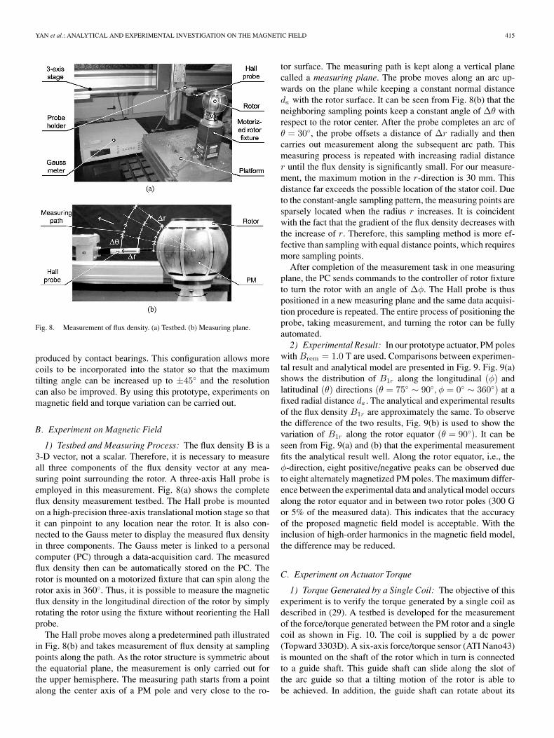
Fig. 8. Measurement of flux density. (a) Testbed. (b) Measuring plane.
produced by contact bearings. This configuration allows morecoils to be incorporated into the stator so that the maximumtilting angle can be increased up to ±45◦ and the resolutioncan also be improved. By using this prototype, experiments onmagnetic field and torque variation can be carried out.
B. Experiment on Magnetic Field
1) Testbed and Measuring Process: The flux density B is a3-D vector, not a scalar. Therefore, it is necessary to measureall three components of the flux density vector at any mea-suring point surrounding the rotor. A three-axis Hall probe isemployed in this measurement. Fig. 8(a) shows the completeflux density measurement testbed. The Hall probe is mountedon a high-precision three-axis translational motion stage so thatit can pinpoint to any location near the rotor. It is also con-nected to the Gauss meter to display the measured flux densityin three components. The Gauss meter is linked to a personalcomputer (PC) through a data-acquisition card. The measuredflux density then can be automatically stored on the PC. Therotor is mounted on a motorized fixture that can spin along therotor axis in 360◦. Thus, it is possible to measure the magneticflux density in the longitudinal direction of the rotor by simplyrotating the rotor using the fixture without reorienting the Hallprobe.
The Hall probe moves along a predetermined path illustratedin Fig. 8(b) and takes measurement of flux density at samplingpoints along the path. As the rotor structure is symmetric aboutthe equatorial plane, the measurement is only carried out forthe upper hemisphere. The measuring path starts from a pointalong the center axis of a PM pole and very close to the ro-
tor surface. The measuring path is kept along a vertical planecalled a measuring plane. The probe moves along an arc up-wards on the plane while keeping a constant normal distanceda with the rotor surface. It can be seen from Fig. 8(b) that theneighboring sampling points keep a constant angle of ∆θ withrespect to the rotor center. After the probe completes an arc ofθ = 30◦, the probe offsets a distance of ∆r radially and thencarries out measurement along the subsequent arc path. Thismeasuring process is repeated with increasing radial distancer until the flux density is significantly small. For our measure-ment, the maximum motion in the r-direction is 30 mm. Thisdistance far exceeds the possible location of the stator coil. Dueto the constant-angle sampling pattern, the measuring points aresparsely located when the radius r increases. It is coincidentwith the fact that the gradient of the flux density decreases withthe increase of r. Therefore, this sampling method is more ef-fective than sampling with equal distance points, which requiresmore sampling points.
After completion of the measurement task in one measuringplane, the PC sends commands to the controller of rotor fixtureto turn the rotor with an angle of ∆φ. The Hall probe is thuspositioned in a new measuring plane and the same data acquisi-tion procedure is repeated. The entire process of positioning theprobe, taking measurement, and turning the rotor can be fullyautomated.
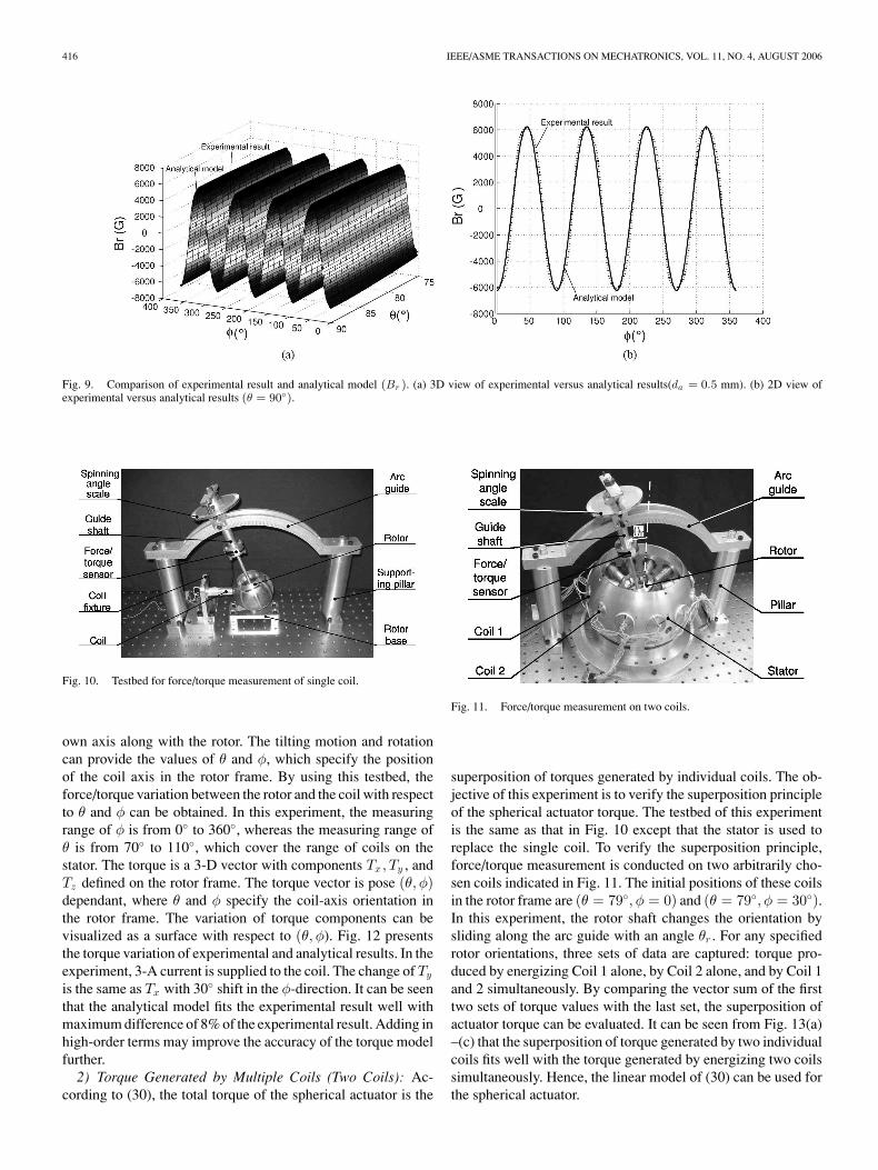
2) Experimental Result: In our prototype actuator, PM poleswith Brem = 1.0 T are used. Comparisons between experimen-tal result and analytical model are presented in Fig. 9. Fig. 9(a)shows the distribution of B1r along the longitudinal (φ) andlatitudinal (θ) directions (θ = 75◦ ∼ 90◦, φ = 0◦ ∼ 360◦) at afixed radial distance da . The analytical and experimental resultsof the flux density B1r are approximately the same. To observethe difference of the two results, Fig. 9(b) is used to show thevariation of B1r along the rotor equator (θ = 90◦). It can beseen from Fig. 9(a) and (b) that the experimental measurementfits the analytical result well. Along the rotor equator, i.e., theφ-direction, eight positive/negative peaks can be observed dueto eight alternately magnetized PM poles. The maximum differ-ence between the experimental data and analytical model occursalong the rotor equator and in between two rotor poles (300 Gor 5% of the measured data). This indicates that the accuracyof the proposed magnetic field model is acceptable. With theinclusion of high-order harmonics in the magnetic field model,the difference may be reduced.
C. Experiment on Actuator Torque
1) Torque Generated by a Single Coil: The objective of thisexperiment is to verify the torque generated by a single coil asdescribed in (29). A testbed is developed for the measurementof the force/torque generated between the PM rotor and a singlecoil as shown in Fig. 10. The coil is supplied by a dc power(Topward 3303D). A six-axis force/torque sensor (ATI Nano43)is mounted on the shaft of the rotor which in turn is connectedto a guide shaft. This guide shaft can slide along the slot ofthe arc guide so that a tilting motion of the rotor is able tobe achieved. In addition, the guide shaft can rotate about its
416 IEEE/ASME TRANSACTIONS ON MECHATRONICS, VOL. 11, NO. 4, AUGUST 2006
Fig. 9. Comparison of experimental result and analytical model (Br ). (a) 3D view of experimental versus analytical results(da = 0.5 mm). (b) 2D view ofexperimental versus analytical results (θ = 90◦).
Fig. 10. Testbed for force/torque measurement of single coil.
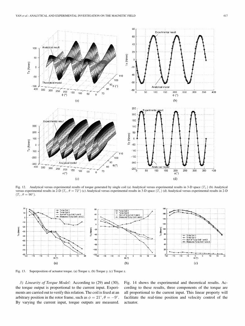
own axis along with the rotor. The tilting motion and rotationcan provide the values of θ and φ, which specify the positionof the coil axis in the rotor frame. By using this testbed, theforce/torque variation between the rotor and the coil with respectto θ and φ can be obtained. In this experiment, the measuringrange of φ is from 0◦ to 360◦, whereas the measuring range ofθ is from 70◦ to 110◦, which cover the range of coils on thestator. The torque is a 3-D vector with components Tx, Ty , andTz defined on the rotor frame. The torque vector is pose (θ, φ)dependant, where θ and φ specify the coil-axis orientation inthe rotor frame. The variation of torque components can bevisualized as a surface with respect to (θ, φ). Fig. 12 presentsthe torque variation of experimental and analytical results. In theexperiment, 3-A current is supplied to the coil. The change of Ty
is the same as Tx with 30◦ shift in the φ-direction. It can be seenthat the analytical model fits the experimental result well withmaximum difference of 8% of the experimental result. Adding inhigh-order terms may improve the accuracy of the torque modelfurther.
2) Torque Generated by Multiple Coils (Two Coils): Ac-cording to (30), the total torque of the spherical actuator is the
Fig. 11. Force/torque measurement on two coils.
superposition of torques generated by individual coils. The ob-jective of this experiment is to verify the superposition principleof the spherical actuator torque. The testbed of this experimentis the same as that in Fig. 10 except that the stator is used toreplace the single coil. To verify the superposition principle,force/torque measurement is conducted on two arbitrarily cho-sen coils indicated in Fig. 11. The initial positions of these coilsin the rotor frame are (θ = 79◦, φ = 0) and (θ = 79◦, φ = 30◦).In this experiment, the rotor shaft changes the orientation bysliding along the arc guide with an angle θr . For any specifiedrotor orientations, three sets of data are captured: torque pro-duced by energizing Coil 1 alone, by Coil 2 alone, and by Coil 1and 2 simultaneously. By comparing the vector sum of the firsttwo sets of torque values with the last set, the superposition ofactuator torque can be evaluated. It can be seen from Fig. 13(a)–(c) that the superposition of torque generated by two individualcoils fits well with the torque generated by energizing two coilssimultaneously. Hence, the linear model of (30) can be used forthe spherical actuator.
YAN et al.: ANALYTICAL AND EXPERIMENTAL INVESTIGATION ON THE MAGNETIC FIELD 417
Fig. 12. Analytical versus experimental results of torque generated by single coil (a) Analytical versus experimental results in 3-D space (Tx ) (b) Analyticalversus experimental results in 2-D (Tx , θ = 72◦) (c) Analytical versus experimental results in 3-D space (Tz ) (d) Analytical versus experimental results in 2-D(Tz , θ = 90◦).
Fig. 13. Superposition of actuator torque. (a) Torque x. (b) Torque y. (c) Torque z.
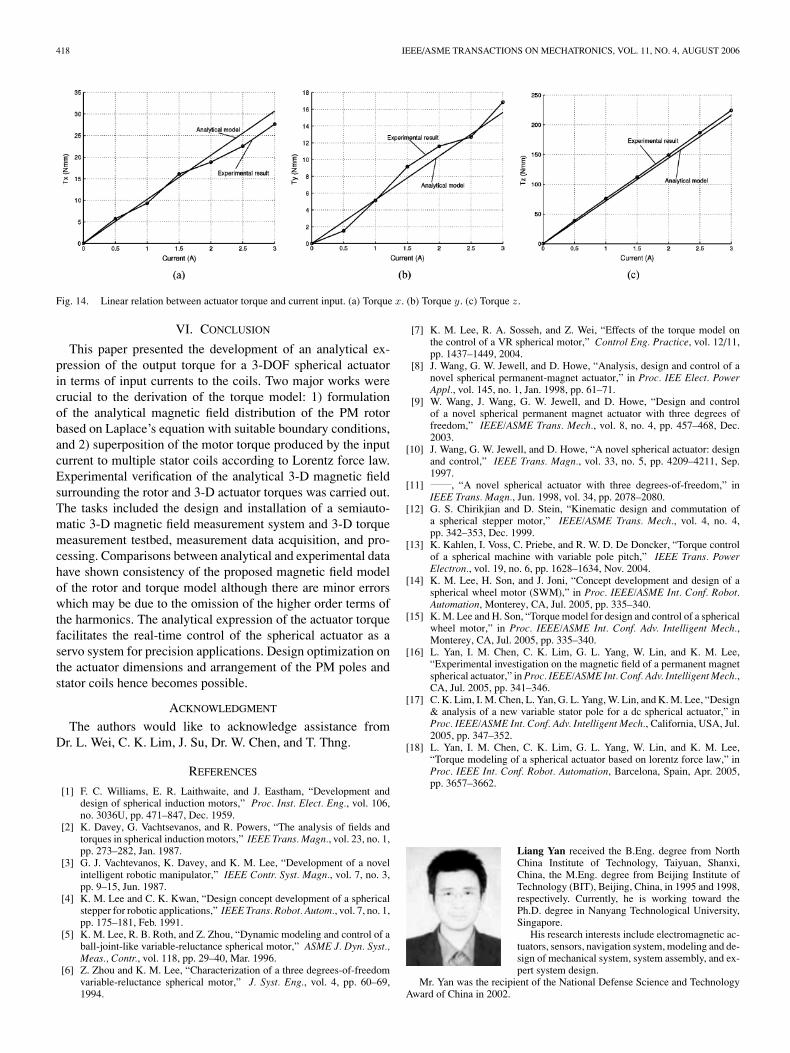
3) Linearity of Torque Model: According to (29) and (30),the torque output is proportional to the current input. Experi-ments are carried out to verify this relation. The coil is fixed at anarbitrary position in the rotor frame, such as φ = 21◦, θ = −9◦.By varying the current input, torque outputs are measured.
Fig. 14 shows the experimental and theoretical results. Ac-cording to these results, three components of the torque areall proportional to the current input. This linear property willfacilitate the real-time position and velocity control of theactuator.
418 IEEE/ASME TRANSACTIONS ON MECHATRONICS, VOL. 11, NO. 4, AUGUST 2006
Fig. 14. Linear relation between actuator torque and current input. (a) Torque x. (b) Torque y. (c) Torque z.
VI. CONCLUSION
This paper presented the development of an analytical ex-pression of the output torque for a 3-DOF spherical actuatorin terms of input currents to the coils. Two major works werecrucial to the derivation of the torque model: 1) formulationof the analytical magnetic field distribution of the PM rotorbased on Laplace’s equation with suitable boundary conditions,and 2) superposition of the motor torque produced by the inputcurrent to multiple stator coils according to Lorentz force law.Experimental verification of the analytical 3-D magnetic fieldsurrounding the rotor and 3-D actuator torques was carried out.The tasks included the design and installation of a semiauto-matic 3-D magnetic field measurement system and 3-D torquemeasurement testbed, measurement data acquisition, and pro-cessing. Comparisons between analytical and experimental datahave shown consistency of the proposed magnetic field modelof the rotor and torque model although there are minor errorswhich may be due to the omission of the higher order terms ofthe harmonics. The analytical expression of the actuator torquefacilitates the real-time control of the spherical actuator as aservo system for precision applications. Design optimization onthe actuator dimensions and arrangement of the PM poles andstator coils hence becomes possible.
ACKNOWLEDGMENT
The authors would like to acknowledge assistance fromDr. L. Wei, C. K. Lim, J. Su, Dr. W. Chen, and T. Thng.
REFERENCES
[1] F. C. Williams, E. R. Laithwaite, and J. Eastham, “Development anddesign of spherical induction motors,” Proc. Inst. Elect. Eng., vol. 106,no. 3036U, pp. 471–847, Dec. 1959.
[2] K. Davey, G. Vachtsevanos, and R. Powers, “The analysis of fields andtorques in spherical induction motors,” IEEE Trans. Magn., vol. 23, no. 1,pp. 273–282, Jan. 1987.
[3] G. J. Vachtevanos, K. Davey, and K. M. Lee, “Development of a novelintelligent robotic manipulator,” IEEE Contr. Syst. Magn., vol. 7, no. 3,pp. 9–15, Jun. 1987.
[4] K. M. Lee and C. K. Kwan, “Design concept development of a sphericalstepper for robotic applications,” IEEE Trans. Robot. Autom., vol. 7, no. 1,pp. 175–181, Feb. 1991.
[5] K. M. Lee, R. B. Roth, and Z. Zhou, “Dynamic modeling and control of aball-joint-like variable-reluctance spherical motor,” ASME J. Dyn. Syst.,Meas., Contr., vol. 118, pp. 29–40, Mar. 1996.
[6] Z. Zhou and K. M. Lee, “Characterization of a three degrees-of-freedomvariable-reluctance spherical motor,” J. Syst. Eng., vol. 4, pp. 60–69,1994.
[7] K. M. Lee, R. A. Sosseh, and Z. Wei, “Effects of the torque model onthe control of a VR spherical motor,” Control Eng. Practice, vol. 12/11,pp. 1437–1449, 2004.
[8] J. Wang, G. W. Jewell, and D. Howe, “Analysis, design and control of anovel spherical permanent-magnet actuator,” in Proc. IEE Elect. PowerAppl., vol. 145, no. 1, Jan. 1998, pp. 61–71.
[9] W. Wang, J. Wang, G. W. Jewell, and D. Howe, “Design and controlof a novel spherical permanent magnet actuator with three degrees offreedom,” IEEE/ASME Trans. Mech., vol. 8, no. 4, pp. 457–468, Dec.2003.
[10] J. Wang, G. W. Jewell, and D. Howe, “A novel spherical actuator: designand control,” IEEE Trans. Magn., vol. 33, no. 5, pp. 4209–4211, Sep.1997.
[11] , “A novel spherical actuator with three degrees-of-freedom,” inIEEE Trans. Magn., Jun. 1998, vol. 34, pp. 2078–2080.
[12] G. S. Chirikjian and D. Stein, “Kinematic design and commutation ofa spherical stepper motor,” IEEE/ASME Trans. Mech., vol. 4, no. 4,pp. 342–353, Dec. 1999.
[13] K. Kahlen, I. Voss, C. Priebe, and R. W. D. De Doncker, “Torque controlof a spherical machine with variable pole pitch,” IEEE Trans. PowerElectron., vol. 19, no. 6, pp. 1628–1634, Nov. 2004.
[14] K. M. Lee, H. Son, and J. Joni, “Concept development and design of aspherical wheel motor (SWM),” in Proc. IEEE/ASME Int. Conf. Robot.Automation, Monterey, CA, Jul. 2005, pp. 335–340.
[15] K. M. Lee and H. Son, “Torque model for design and control of a sphericalwheel motor,” in Proc. IEEE/ASME Int. Conf. Adv. Intelligent Mech.,Monterey, CA, Jul. 2005, pp. 335–340.
[16] L. Yan, I. M. Chen, C. K. Lim, G. L. Yang, W. Lin, and K. M. Lee,“Experimental investigation on the magnetic field of a permanent magnetspherical actuator,” in Proc. IEEE/ASME Int. Conf. Adv. Intelligent Mech.,CA, Jul. 2005, pp. 341–346.
[17] C. K. Lim, I. M. Chen, L. Yan, G. L. Yang, W. Lin, and K. M. Lee, “Design& analysis of a new variable stator pole for a dc spherical actuator,” inProc. IEEE/ASME Int. Conf. Adv. Intelligent Mech., California, USA, Jul.2005, pp. 347–352.
[18] L. Yan, I. M. Chen, C. K. Lim, G. L. Yang, W. Lin, and K. M. Lee,“Torque modeling of a spherical actuator based on lorentz force law,” inProc. IEEE Int. Conf. Robot. Automation, Barcelona, Spain, Apr. 2005,pp. 3657–3662.
Liang Yan received the B.Eng. degree from NorthChina Institute of Technology, Taiyuan, Shanxi,China, the M.Eng. degree from Beijing Institute ofTechnology (BIT), Beijing, China, in 1995 and 1998,respectively. Currently, he is working toward thePh.D. degree in Nanyang Technological University,Singapore.
His research interests include electromagnetic ac-tuators, sensors, navigation system, modeling and de-sign of mechanical system, system assembly, and ex-pert system design.
Mr. Yan was the recipient of the National Defense Science and TechnologyAward of China in 2002.
YAN et al.: ANALYTICAL AND EXPERIMENTAL INVESTIGATION ON THE MAGNETIC FIELD 419
I-Ming Chen (M’95–SM’06) received the B.S. de-gree from the National Taiwan University, Taipei,Taiwan, in 1986, and the M.S. and the Ph.D. de-grees from the California Institute of Technology,Pasadena, in 1989 and 1994, respectively.
Since 1995, he has been with the School ofMechanical and Aerospace Engineering of NanyangTechnological University, Singapore. In 1999, he wasJSPS Visiting Scholar at Kyoto University, Japan. In2004, he was a Visiting Scholar in the Department ofMechanical Engineering of Massachusetts Institute
of Technology (MIT), Cambridge. He is also the Adjunct Professor with XianJiao Tong University, Xian, China. He is the author of more than 130 technical ar-ticles in refereed international journals and conferences. His research interestsinclude reconfigurable automation, biomedical applications of reconfigurablerobotic systems, parallel kinematics machines (PKM), biomorphic underwaterrobots, and smart material-based actuators.
Dr. Chen is a Fellow of the Singapore-MIT Alliance under the ManufacturingSystems and Technology (MST) Program. He is serving on the editorial boardsof IEEE/ASME TRANSACTIONS ON MECHATRONICS, Robotica-InternationalJournal, and the steering committee of CISM-IFToMM Symposium on RobotDesign, Dynamics and Control (ROMANSY). He is also General Chairmanof the 2009 IEEE/ASME International Conference on Advanced IntelligentMechatronics (AIM2009) in Singapore. He is a Member of ASME, Chairman ofthe Prototyping for Robotics and Automation Technical Committee under IEEERobotics and Automation Society, and a Member of the RoboCup SingaporeNational Committee.
Guilin Yang (M’02) received the B.Eng. and theM.Eng. degrees from the Jilin University of Tech-nology (now Jilin University), Changchun, China, in1985 and 1988, respectively, and the Ph.D. degreefrom Nanyang Technological University, Singapore,in 1999.
In 1988, he joined the School of MechanicalEngineering, Shijiazhuang Railway Institute, Hebei,China, as a Lecturer, and was a Division Head andthen the Vice Dean of the school for nearly sevenyears. Currently, he is a Research Scientist and the
Deputy Group Manager of the Mechanics Group, Singapore Institute of Man-ufacturing Technology, Singapore. He is the author of over 100 technicalpapers published in refereed international journals and conferences. His cur-rent research interests include computational kinematics, multi-body dynamics,parallel-kinematics machines, modular robots, flexure-based precision mech-anisms, electromagnetic actuators, rehabilitation devices, and industrial robotsystems.
Dr. Yang is a Technical Committee Member of Robotics of InternationalFederation for the Promotion of Mechanism and Machine Science and the Sec-retary of the Singapore Chapter of the IEEE Robotics and Automation Society.
Kok-Meng Lee (M’89–SM’02–F’05) received theB.S. degree from the State University of New York,Buffalo, in 1980, and the S.M. and Ph.D. degreesfrom the Massachusetts Institute of Technology,Cambridge, in 1982 and 1985, respectively.
Currently, he is a Professor at the Woodruff Schoolof Mechanical Engineering at the Georgia Institute ofTechnology, Atlanta. He is the holder of eight patentsin machine vision, 3-DOF spherical motor/encoder,and live-bird handling system. His research interestsinclude system dynamics/control, robotics, automa-
tion, and mechatronics.Dr. Lee is a Fellow of ASME. He was the recipient of the National Science
Foundation (NSF) Presidential Young Investigator, Sigma Xi Junior Faculty Re-search, International Hall of Fame New Technology, and Kayamori Best Paperawards.