Embed Size (px)
Citation preview
IEEE/ASME TRANSACTIONS ON MECHATRONICS, VOL. 18, NO. 5, OCTOBER 2013 1485
Meshworm: A Peristaltic Soft Robot WithAntagonistic Nickel Titanium Coil Actuators
Sangok Seok, Cagdas Denizel Onal, Member, IEEE, Kyu-Jin Cho, Member, IEEE, Robert J. Wood,Daniela Rus, Fellow, IEEE, and Sangbae Kim
Abstract—This paper presents the complete development andanalysis of a soft robotic platform that exhibits peristaltic locomo-tion. The design principle is based on the antagonistic arrange-ment of circular and longitudinal muscle groups of Oligochaetes.Sequential antagonistic motion is achieved in a flexible braidedmesh-tube structure using a nickel titanium (NiTi) coil actuatorswrapped in a spiral pattern around the circumference. An en-hanced theoretical model of the NiTi coil spring describes the com-bination of martensite deformation and spring elasticity as a func-tion of geometry. A numerical model of the mesh structures revealshow peristaltic actuation induces robust locomotion and details thedeformation by the contraction of circumferential NiTi actuators.Several peristaltic locomotion modes are modeled, tested, and com-pared on the basis of speed. Utilizing additional NiTi coils placedlongitudinally, steering capabilities are incorporated. Propriocep-tive potentiometers sense segment contraction, which enables thedevelopment of closed-loop controllers. Several appropriate con-trol algorithms are designed and experimentally compared basedon locomotion speed and energy consumption. The entire mechan-ical structure is made of flexible mesh materials and can withstandsignificant external impact during operation. This approach allowsa completely soft robotic platform by employing a flexible controlunit and energy sources.1
Index Terms—Bioinspired robotics, earthworm robot, nickeltitanium (NiTi) coil springs, peristaltic locomotion, soft robotics,shape memory alloy (SMA) actuation.
I. INTRODUCTION
IN the last several1 decades, many robotics researchers havedevoted themselves to develop soft robots inspired by biol-
ogy [1], [2]. Soft robots are especially beneficial for delicatetasks, rough terrain negotiation, recovery from overturning, andsafety in human interaction [3]. Developing soft actuators is oneof the critical requirements to enable these structures.
Manuscript received March 28, 2012; accepted May 9, 2012. Date of pub-lication July 5, 2012; date of current version July 11, 2013. Recommended byTechnical Editor Y. Sun. This work is supported in part by the Defense Ad-vanced Research Projects Agency (DARPA) under Grant W911NF-08-C-0060(Chemical Robots).
S. Seok and S. Kim are with the Department of Mechanical Engineering,Massachusetts Institute of Technology, Cambridge, MA 02139 USA (e-mail:[email protected]; [email protected]).
C. D. Onal and D. Rus are with the Computer Science and Artificial In-telligence Laboratory, Massachusetts Institute of Technology, Cambridge, MA02139 USA (e-mail: [email protected]; [email protected]).
K. J. Cho is with the School of Mechanical and Aerospace Engineering, SeoulNational University, Seoul 151-742, Korea (e-mail: [email protected]).
R. J. Wood is with the School of Engineering and Applied Sciences, HarvardUniversity, Cambridge, MA 02138 USA (e-mail: [email protected]).
Color versions of one or more of the figures in this paper are available onlineat http://ieeexplore.ieee.org.
Digital Object Identifier 10.1109/TMECH.2012.22040701Some material in this paper has been adapted from two papers: [4] and [5]
Several soft actuators such as ionic polymer metal composite(IPMC), electroactive polymers (EAP), nickel titanium (NiTi)shape memory alloy (SMA) wires, and springs are proposed.IPMC actuators are light and enable large bending displace-ments, but can generate only a small force. EAPs generate largedeformations, but generally require a large electric field andrigid frame structure, with a small force output as well. SMAactuators are able to generate large displacements with simplemechanisms. They, however, exhibit slow cycle frequencies dueto the passive cooling on the restoration phase [6]. Even so,SMA spring actuators have a extremely large energy densityper cycle (1314 J/kg) [4] and are promising for soft robots withmodest speed requirements.
Many soft-bodied animals such as earthworms, sea cucum-bers, snails that use peristalsis for locomotion provide inspi-ration for soft robotic platforms [7]. There are several bene-fits of the combination of a soft body with peristaltic locomo-tion. A soft body, which is essentially compliant, exhibits largestrains [1] and enables the robot to traverse small openingsand reconstitute shape, and survives from large impact forceon falling. Peristaltic locomotion is slow but stable locomotionalternative [8] with reduced noise generation and also requiresa smaller form-factor than legged or wheeled locomotion [9].
Due to these benefits, several soft-bodied robotic peristalticlocomotion platforms have been developed for confined spacesuch as endoscopy or reconnaissance purposes. In [10], a flex-ible endoscope is developed. This device uses balloons andextensors that vary their length alternately to achieve peristalticmotion. Likewise, Mangan et al. developed serial segmentedpneumatic actuators, which create peristaltic locomotion of anendoscope [11]. Another work utilized rubber cells filled witha water-based magnetic fluid instead of pneumatic actuators.These cells expand sequentially by an external moving mag-netic field to generate peristaltic locomotion [9]. On the otherhand, Kim et al. developed a capsule endoscope with a direc-tional frictional skin, actuated by piezoelectricity, which createsreciprocal motion of two halves [12]. The authors later replacedthe actuation mechanism to SMA springs in [6]. Similarly, lon-gitudinal SMA spring actuators were used to actuate multipleelastic segments in [13], where the stored elastic energy in thesegments extends the structure. Recently, large scale peristalticlocomotion has been demonstrated by a cylindrical robot witha braided mesh body made of brake cable sheating, which hassteel cables wrapped around. A single-cam mechanism on oneend of the body creates traveling waves along the length of therobot by applying tension on the steel cables [14].
Our approach to develop a soft worm-like crawling robotenables many new features in comparison to the state of the
1083-4435/$31.00 © 2012 IEEE
1486 IEEE/ASME TRANSACTIONS ON MECHATRONICS, VOL. 18, NO. 5, OCTOBER 2013
art. In the literature, similar robotic systems typically utilizerigid mechanical components. The sizes of these componentsare significantly large, which limits the deformability of thebody. Meshworm, the subject of this paper, utilizes flexiblemechanical components in its mechanism for actuation. Theonly rigid parts on the body are electrical in nature: a batteryand a printed circuit board. Having a flexible mechanical bodyand no rigid transmission elements reduces limitations on thesize of the robot, making it more compact. Additionally, as rigidmechanical components are more prone to failure upon impact,our robot is safer.
In this paper, we describe an entirely soft mobile roboticplatform that exhibits peristaltic locomotion. The robot utilizescoiled NiTi fibrillar actuators. It consists of a series of segmentsthat contract to induce peristalsis. We achieve steering by ad-ditional longitudinal actuators that contract to bend the tubularbody in an intended direction. Iterative learning control (ILC)algorithms regulate the contraction period of each segment tooptimize underlying objective functions of performance.
The contributions of this study are as follows.1) Modeling, design, fabrication, and evaluation of NiTi
SMA coils as artificial muscle fibers.2) Development of a soft mobile robot, tagged the Mesh-
worm, consisting of multiple contractile segments under-going peristaltic crawling locomotion.
3) Development of control algorithms realize optimized per-formance and steering.
The organization of this paper is as follows. Section II inves-tigates coil NiTi wires used as compact fibrillar actuator. Wemodel and identify parameters to tune the behavior of these ac-tuators. In Section III, we present a peristaltic soft mobile robotinspired by earthworm locomotion observed in nature. We out-line basic locomotion principles of this robot, using sequentialcontraction of multiple NiTi coils wound around the cylindricalbody. In Section IV, we develop ILC algorithms using variousobjective function to optimize the performance of the robot.Section V discusses the addition of longitudinal actuator fibersto implement steering.
II. NITI COIL ACTUATORS AS MICROARTIFICIAL
MUSCLE FIBERS
NiTi) is one of the well-known SMA materials that generatemechanical work by phase change. Despite its low efficiency, ithas a high energy density, which gives the ability to develop rela-tively small scale actuators compared to other types of actuatorsmentioned in Section I. In a solid state phase transformation,the crystal structure of the NiTi compound transforms frommartensite to austenite states with up to 7% strain change [15].For larger displacements, coiled spring NiTi wires can be used.
Various NiTi models suggested from the 1990s are discussedin [16]. These are mostly thermodynamic models of variousforms of NiTi such as wires, tubes, and sheets. Coiled springNiTi models were discussed in [6], and [17]–[19]. These models,however, are relatively incomplete. The existing models focuson the mechanical coiled spring equations using different shearmoduli for the martensite and austenite phases, overlooking the
change in the free length of the spring due to the phase tran-sition. A more appropriate model, which is useful for a designof coiled spring NiTi is proposed in Section II-A. This modelcombines the mechanical and thermodynamic aspects of NiTicoil actuators to describe the overall martensite deformation andthe geometrical spring effect together. We use this model as aguideline for actuator design for the Meshworm robot.
There are two major steps to fabricate NiTi coil springs. First,an NiTi wire is wound around a straight core, and then the coiledNiTi wire is annealed at a certain high temperature in order toreset the memorized shape as a spring. During the annealingprocess, mechanical properties and the actuation performanceof NiTi springs are determined by the annealing temperature. InSection II-B, the manufacturing process is detailed and experi-mental data between deflection and force under various anneal-ing temperatures are presented.
A. Modeling of NiTi Coil Actuators
Even though NiTi spring actuators are widely used [6],[17]–[19], complete design models have not been developedyet. Recent works utilize the mechanical coiled spring equationwith two shear moduli, GM and GA which are the marten-site and austenite phases, respectively. However, none of thesemodels consider the free length change of the NiTi spring dueto phase change. The free length of 100% austenite phase xAo
is shorter than the free length of 100% martensite xM o .There are two major physical phenomena in NiTi coil spring
deformation. One is the free length change due to the phasetransformation explained earlier, and the other is the springconstant difference between the martensite and austenite states.The spring constant in the austenite phase is around 2–3 timesgreater than in the martensite phase [16].
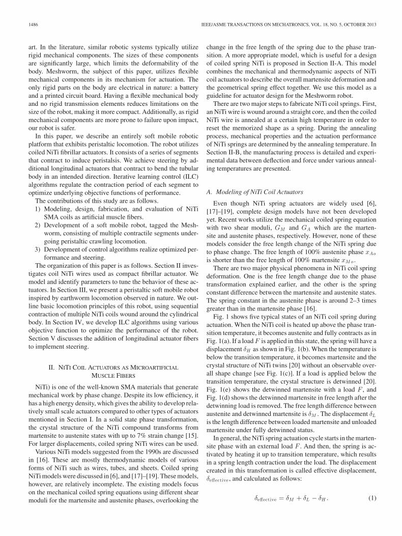
Fig. 1 shows five typical states of an NiTi coil spring duringactuation. When the NiTi coil is heated up above the phase tran-sition temperature, it becomes austenite and fully contracts as inFig. 1(a). If a load F is applied in this state, the spring will have adisplacement δH as shown in Fig. 1(b). When the temperature isbelow the transition temperature, it becomes martensite and thecrystal structure of NiTi twins [20] without an observable over-all shape change [see Fig. 1(c)]. If a load is applied below thetransition temperature, the crystal structure is detwinned [20].Fig. 1(e) shows the detwinned martensite with a load F , andFig. 1(d) shows the detwinned martensite in free length after thedetwinning load is removed. The free length difference betweenaustenite and detwinned martensite is δM . The displacement δL
is the length difference between loaded martensite and unloadedmartensite under fully detwinned status.
In general, the NiTi spring actuation cycle starts in the marten-site phase with an external load F . And then, the spring is ac-tivated by heating it up to transition temperature, which resultsin a spring length contraction under the load. The displacementcreated in this transformation is called effective displacement,δeffective , and calculated as follows:
δeffective = δM + δL − δH . (1)
SEOK et al.: MESHWORM: A PERISTALTIC SOFT ROBOT WITH ANTAGONISTIC NICKEL TITANIUM COIL ACTUATORS 1487
Fig. 1. Five representative states of an NiTi coil spring actuator: (a) full austen-ite without load, (b) full austenite with load, (c) twinned martensite without load,(d) fully detwinned martensite without load, and (e) fully detwinned martensitewith load.
Here, each δi value, where i ∈ {H,L,M}, corresponds tothe displacement of the coil. Using the general coiled springdeflection equation, δi is a function of an external load F , overallspring diameter D, NiTi wire diameter d, number of activecoils in the spring n, and the shear modulus of the spring afterannealing G
δi =8FD3n
Gd4 . (2)
The shear strain γ of the spring is
γ =τ
G(3)
and the shear stress τ is
τ =8FDκ
πd3 (4)
where κ is a stress correction factor. From Wahl’s formula [21],κ is
κ =4C − 14C − 4
+0.615
C. (5)
Here C is the spring index, defined as follows:
C =D
d. (6)
Using this analysis, the difference of the free length between theaustenite and martensite phases δM can be calculated from (2)through (4) as
δM =πγD2n
dκ. (7)
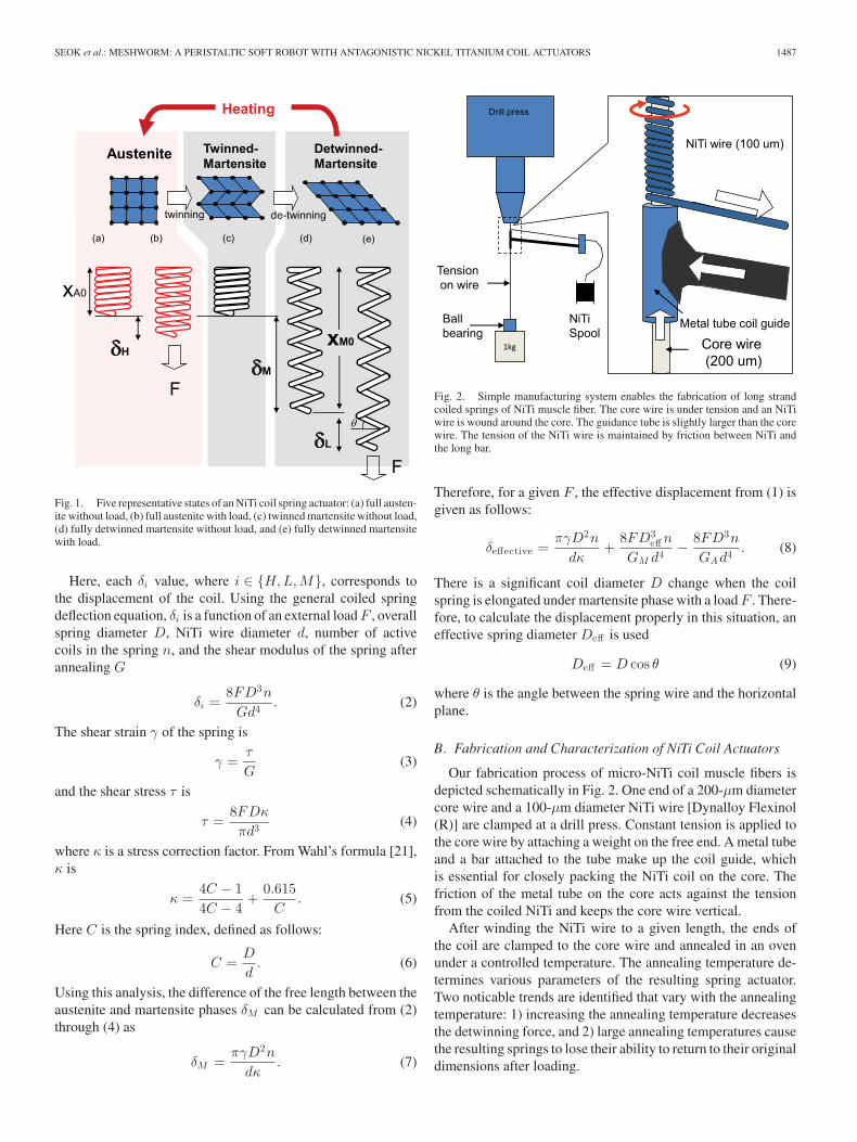
Fig. 2. Simple manufacturing system enables the fabrication of long strandcoiled springs of NiTi muscle fiber. The core wire is under tension and an NiTiwire is wound around the core. The guidance tube is slightly larger than the corewire. The tension of the NiTi wire is maintained by friction between NiTi andthe long bar.
Therefore, for a given F , the effective displacement from (1) isgiven as follows:
δeffective =πγD2n
dκ+
8FD3eff n
GM d4 − 8FD3n
GAd4 . (8)
There is a significant coil diameter D change when the coilspring is elongated under martensite phase with a load F . There-fore, to calculate the displacement properly in this situation, aneffective spring diameter Deff is used
Deff = D cos θ (9)
where θ is the angle between the spring wire and the horizontalplane.
B. Fabrication and Characterization of NiTi Coil Actuators
Our fabrication process of micro-NiTi coil muscle fibers isdepicted schematically in Fig. 2. One end of a 200-μm diametercore wire and a 100-μm diameter NiTi wire [Dynalloy Flexinol(R)] are clamped at a drill press. Constant tension is applied tothe core wire by attaching a weight on the free end. A metal tubeand a bar attached to the tube make up the coil guide, whichis essential for closely packing the NiTi coil on the core. Thefriction of the metal tube on the core acts against the tensionfrom the coiled NiTi and keeps the core wire vertical.
After winding the NiTi wire to a given length, the ends ofthe coil are clamped to the core wire and annealed in an ovenunder a controlled temperature. The annealing temperature de-termines various parameters of the resulting spring actuator.Two noticable trends are identified that vary with the annealingtemperature: 1) increasing the annealing temperature decreasesthe detwinning force, and 2) large annealing temperatures causethe resulting springs to lose their ability to return to their originaldimensions after loading.
1488 IEEE/ASME TRANSACTIONS ON MECHATRONICS, VOL. 18, NO. 5, OCTOBER 2013
Detwinning is a passive process that returns the actuatedNiTi coils in the twinned martensite state back to the fullydetwinned martensite state through martensite transformation.This requires external work, such that a certain amount of ten-sile force pulls the coils to extend them, transforming theirstate in the process. This force is strongly dependant on theannealing temperature, and is a mechanical characteristic of theactuators. When used in an antagonistic configuration, such thatthe actuation of one coil detwins the other, this characteristicforce requirement affects the full cycle work efficiency of theactuators.
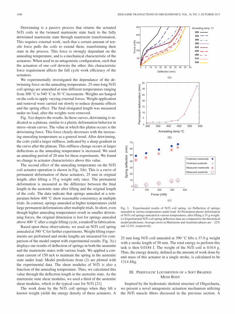
We experimentally investigated the dependance of the de-twinning force on the annealing temperature. 25-mm-long NiTicoil springs are annealted at nine different temperatures rangingfrom 300 ◦C to 540 ◦C in 30 ◦C increments. Weights are hangedon the coils to apply varying external forces. Weight applicationand removal were carried out slowly to reduce dynamic effectsand the spring effect. The final elongated length was measuredunder no load, after the weights were removed.
Fig. 3(a) depicts the results. In these curves, detwinning is in-dicated as a plateau, similar to a plastic deformation behavior instress–strain curves. The value at which this plateu occurs is thedetwinning force. This force clearly decreases with the increas-ing annealing temperature as a general trend. After detwinning,the coils yield a larger stiffness, indicated by a sharp gradient inthe curve after the plateau. This stiffness change occurs at largerdeflections as the annealing temperature is increased. We usedan annealing period of 20 min for these experiments. We foundno change in actuator characteristics above this value.
The second effect of the annealing temperature on the NiTicoil actuator operation is shown in Fig. 3(b). This is a curve ofpermanent deformation of these actuators, 25 mm in originallength, after lifting a 35-g weight only once. The permanentdeformation is measured as the difference between the finallength in the austenite state after lifting and the original lengthof the coils. The data indicate that springs annealed at a tem-perature below 400 ◦C show reasonable consistency at multipletrials. In contrast, springs annealed at higher temperatures yieldlarge permanent deformations after multiple trials. In short, eventhough higher annealing temperatures result in smaller detwin-ning forces, the original dimension is lost for springs annealedabove 400 ◦C after a single lifting cycle, a tradeoff in fabrication.
Based upon these observations, we used an NiTi coil springannealed at 390 ◦C for further experiments. Weight lifting exper-iments are performed and stroke lengths are measured for com-parison of the model output with experimental results. Fig. 3(c)displays our results of deflection of springs in both the austeniteand the martensite states with various loads. We applied a con-stant current of 150 mA to maintain the spring in the austenitestate under load. Model predictions from (2) are plotted withthe experimental data. The shear modulus of NiTi is also afunction of the annealing temperature. Thus, we calculated thisvalue through the deflection length in the austenite state. As themartensite state shear modulus, we used a third of the austeniteshear modulus, which is the typical case for NiTi [21].
The work done by the NiTi coil springs when they lift aknown weight yields the energy density of these actuators. A
(a)
(b)
(c)
Fig. 3. Experimental results of NiTi coil spring. (a) Deflection of springsannealed at various temperatures under load. (b) Permanent plastic deformationof NiTi coil springs annealed at various temperatures, after lifting a 35-g weight.(c) Experimental NiTi coil spring deflection data are compared to the theoreticalmodel predictions: Average errors in Martensite and Austenite phases are−22%and 12.4%, respectively.
25 mm long NiTi coil annealed at 390 ◦C lifts a 37.9-g weightwith a stroke length of 50 mm. The total energy to perform thistask is then 0.0184 J. The weight of the NiTi coil is 0.014 g.Thus, the energy density, defined as the amount of work done byunit mass of this actuator in a single stroke, is calculated to be1314 J/kg.
III. PERISTALTIC LOCOMOTION OF A SOFT BRAIDED
MESH BODY
Inspired by the hydrostatic skeletal structure of Oligochaeta,we present a novel antagonistic actuation mechanism utilizingthe NiTi muscle fibers discussed in the previous section. A
SEOK et al.: MESHWORM: A PERISTALTIC SOFT ROBOT WITH ANTAGONISTIC NICKEL TITANIUM COIL ACTUATORS 1489
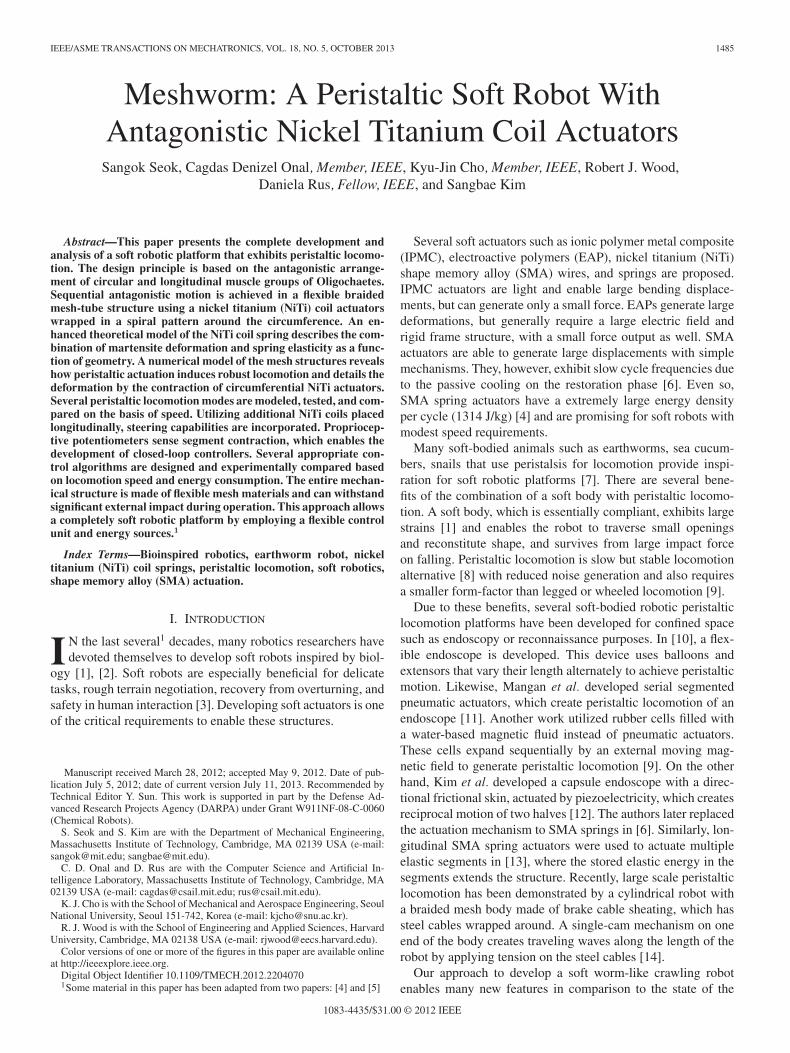
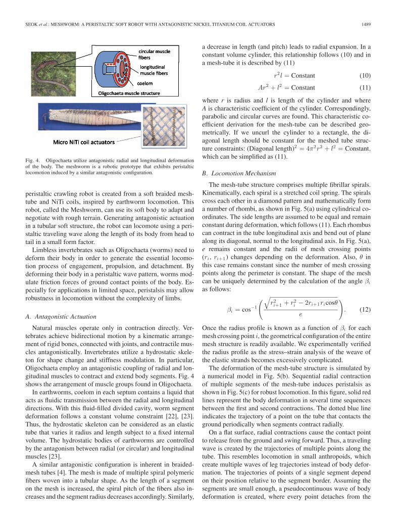
Fig. 4. Oligochaeta utilize antagonistic radial and longitudinal deformationof the body. The meshworm is a robotic prototype that exhibits peristalticlocomotion induced by a similar antagonistic configuration.
peristaltic crawling robot is created from a soft braided mesh-tube and NiTi coils, inspired by earthworm locomotion. Thisrobot, called the Meshworm, can use its soft body to adapt andnegotiate with rough terrain. Generating antagonistic actuationin a tubular soft structure, the robot can locomote using a peri-staltic traveling wave along the length of its body from head totail in a small form factor.
Limbless invertebrates such as Oligochaeta (worms) need todeform their body in order to generate the essential locomo-tion process of engagement, propulsion, and detachment. Bydeforming their body in a peristaltic wave pattern, worms mod-ulate friction forces of ground contact points of the body. Es-pecially for applications in limited space, peristalsis may allowrobustness in locomotion without the complexity of limbs.
A. Antagonistic Actuation
Natural muscles operate only in contraction directly. Ver-tebrates achieve bidirectional motion by a kinematic arrange-ment of rigid bones, connected with joints, and contractile mus-cles antagonistically. Invertebrates utilize a hydrostatic skele-ton for shape change and stiffness modulation. In particular,Oligochaeta employ an antagonistic coupling of radial and lon-gitudinal muscles to contract and extend body segments. Fig. 4shows the arrangement of muscle groups found in Oligochaeta.
In earthworms, coelom in each septum contains a liquid thatacts as fluidic transmission between the radial and longitudinaldirections. With this fluid-filled divided cavity, worm segmentdeformation follows a constant volume constraint [22], [23].Thus, the hydrostatic skeleton can be considered as an elastictube that varies it radius and length subject to a fixed internalvolume. The hydrostatic bodies of earthworms are controlledby the antagonism between radial (or circular) and longitudinalmuscles [23].
A similar antagonistic configuration is inherent in braided-mesh tubes [4]. The mesh is made of multiple spiral polymericfibers woven into a tubular shape. As the length of a segmenton the mesh is increased, the spiral pitch of the fibers also in-creases and the segment radius decreases accordingly. Similarly,
a decrease in length (and pitch) leads to radial expansion. In aconstant volume cylinder, this relationship follows (10) and ina mesh-tube it is described by (11)
r2 l = Constant (10)
Ar2 + l2 = Constant (11)
where r is radius and l is length of the cylinder and whereA is characteristic coefficient of the cylinder. Correspondingly,parabolic and circular curves are found. This characteristic co-efficient derivation for the mesh-tube can be described geo-metrically. If we uncurl the cylinder to a rectangle, the di-agonal length should be constant for the meshed tube struc-ture constraints: (Diagonal length)2 = 4π2r2 + l2 = Constant,which can be simplified as (11).
B. Locomotion Mechanism
The mesh-tube structure comprises multiple fibrillar spirals.Kinematically, each spiral is a stretched coil spring. The spiralscross each other in a diamond pattern and mathematically forma number of rhombi, as shown in Fig. 5(a) using cylindrical co-ordinates. The side lengths are assumed to be equal and remainconstant during deformation, which follows (11). Each rhombuscan contract in the tube longitudinal axis and bend out of planealong its diagonal, normal to the longitudinal axis. In Fig. 5(a),e remains constant and the radii of mesh crossing points(ri , ri+1) changes depending on the deformation. Also, θ inthis case remains constant since the number of mesh crossingpoints along the perimeter is constant. The shape of the meshcan be uniquely determined by the calculation of the angle βi
as follows:
βi = cos−1
(√r2i+1 + r2
i − 2ri+1ricosθ
e
). (12)
Once the radius profile is known as a function of βi for eachmesh crossing point i, the geometrical configuration of the entiremesh structure is readily available. We experimentally verifiedthe radius profile as the stress–strain analysis of the weave ofthe elastic strands becomes excessively complicated.
The deformation of the mesh-tube structure is simulated bya numerical model in Fig. 5(b). Sequential radial contractionof multiple segments of the mesh-tube induces peristalsis asshown in Fig. 5(c) for robust locomotion. In this figure, solid redlines represent the body deformation in several time sequencesbetween the first and second contractions. The dotted blue lineindicates the trajectory of a point on the tube that contacts theground periodically when segments contract radially.
On a flat surface, radial contractions cause the contact pointto release from the ground and swing forward. Thus, a travelingwave is created by the trajectories of multiple points along thetube. This resembles locomotion in small anthropoids, whichcreate multiple waves of leg trajectories instead of body defor-mation. The trajectories of points of a single segment dependon their position relative to the segment border. Assuming thesegments are small enough, a pseudocontinuous wave of bodydeformation is created, where every point detaches from the
1490 IEEE/ASME TRANSACTIONS ON MECHATRONICS, VOL. 18, NO. 5, OCTOBER 2013
(a) (b)
(c) (d)
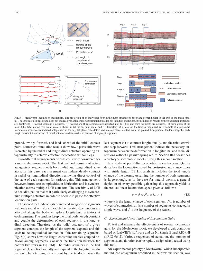
Fig. 5. Meshworm locomotion mechanism. The projection of an individual fiber in the mesh structure to the plane perpendicular to the axis of the mesh-tube.(a) The length of a spiral strand does not change over antagonistic deformation but changes in radius and height. (b) Simulation results of three actuation instancesare displayed: (i) second segment is actuated, (ii) second and third segments are actuated, and (iii) first and third segments are actuated. (c) Simulation of themesh-tube deformation (red solid lines) is shown in (i) the saggital plane, and (ii) trajectory of a point on the tube is magnified. (d) Example of a peristalticlocomotion sequence by induced antagonism in the sagittal plane. The dotted red line represents contact with the ground. Longitudinal tendons keep the bodylength constant. Contraction of radial actuators induces radial expansion of adjacent segments.
ground, swings forward, and lands ahead of the initial contactpoint. Numerical simulation results show how a peristaltic waveis created by the radial and longitudinal actuators operating an-tagonistically to achieve effective locomotion without legs.
Two different arrangements of NiTi coils were considered fora mesh-tube worm robot. The first method consists of activeantagonistic segments with both radial and longitudinal actu-ators. In this case, each segment can independently contractin radial or longitudinal directions allowing direct control ofthe state of each segment for various gaits. This arrangement,however, introduces complexities in fabrication and in synchro-nization across multiple NiTi actuators. The sensitivity of NiTito heat dissipation makes it particularly challenging to synchro-nize multiple actuators in order to operate in phase for effectivelocomotion gaits.
The second method consists of induced antagonistic segmentswith only radial actuators. Flexible but inextensible tendons areattached along the body to replace longitudinal actuators ateach segment. The tendons keep the total body length constantand couple the deformation of each segment in the longitu-dinal direction. Therefore, as the radial actuators of a givensegment contract, the length of the segment expands and thisleads to the longitudinal contraction of the remaining segments.Fig. 5(d) shows how the length constraint enables coupled be-havior among segments. Consider the transition between thebottom two rows in Fig. 5(d). The radial actuators in the firstsegment (1) contract radially and expand in the longitudinal di-rection. The total length constraint by the tendons causes the
last segment (4) to contract longitudinally, and the robot crawlsone step forward. This arrangement induces the necessary an-tagonism between the deformation in longitudinal and radial di-rections without a passive spring return. Section III-C describesa prototype soft mobile robot utilizing this second method.
In a study of peristaltic locomotion in earthworms, Quillindescribes the locomotion speed by protrusion and stance timeswith stride length [7]. His analysis includes the total lengthchange of the worms. Assuming the number of body segmentsis large enough, as is the case for natural worms, a generaldepiction of every possible gait using this approach yields atheoretical linear locomotion speed given as follows:
v = δ × Nw × lw × f (13)
where δ is the length change of each segment, Nw is number ofwaves of contraction, lw is a number of segments contracted insingle wave, and f is the frequency of the waves.
C. Experimental Investigation of Locomotion Gaits
To test and measure the effectiveness of several locomotiongaits for the Meshworm robot, we developed a gait controllerbased on LabVIEW software and an NI Single-Board RIO (NIsbRIO-9642). Various sequences of actuation, the number ofsegments, and duration can be rapidly assigned and tested usingthis tool.
An experimental prototype Meshworm, which incorporatesthe induced antagonism described in the previous section, was
SEOK et al.: MESHWORM: A PERISTALTIC SOFT ROBOT WITH ANTAGONISTIC NICKEL TITANIUM COIL ACTUATORS 1491
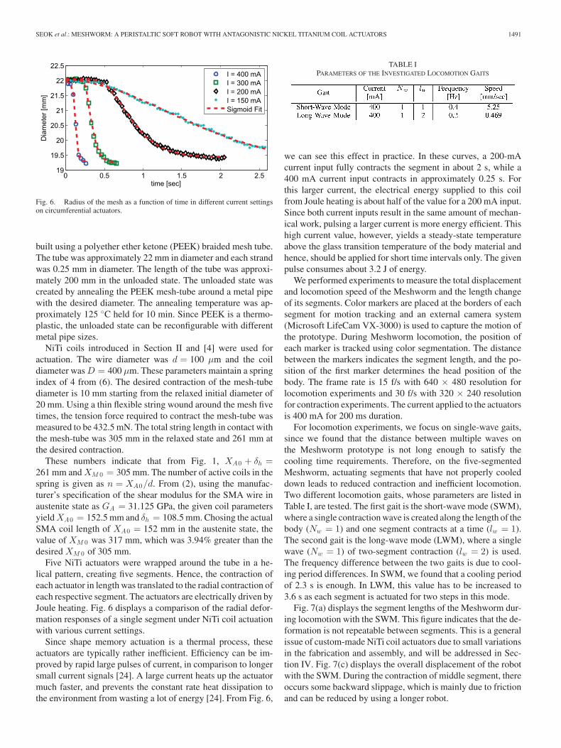
Fig. 6. Radius of the mesh as a function of time in different current settingson circumferential actuators.
built using a polyether ether ketone (PEEK) braided mesh tube.The tube was approximately 22 mm in diameter and each strandwas 0.25 mm in diameter. The length of the tube was approxi-mately 200 mm in the unloaded state. The unloaded state wascreated by annealing the PEEK mesh-tube around a metal pipewith the desired diameter. The annealing temperature was ap-proximately 125 ◦C held for 10 min. Since PEEK is a thermo-plastic, the unloaded state can be reconfigurable with differentmetal pipe sizes.
NiTi coils introduced in Section II and [4] were used foractuation. The wire diameter was d = 100 μm and the coildiameter was D = 400 μm. These parameters maintain a springindex of 4 from (6). The desired contraction of the mesh-tubediameter is 10 mm starting from the relaxed initial diameter of20 mm. Using a thin flexible string wound around the mesh fivetimes, the tension force required to contract the mesh-tube wasmeasured to be 432.5 mN. The total string length in contact withthe mesh-tube was 305 mm in the relaxed state and 261 mm atthe desired contraction.
These numbers indicate that from Fig. 1, XA0 + δh =261 mm and XM 0 = 305 mm. The number of active coils in thespring is given as n = XA0/d. From (2), using the manufac-turer’s specification of the shear modulus for the SMA wire inaustenite state as GA = 31.125 GPa, the given coil parametersyield XA0 = 152.5 mm and δh = 108.5 mm. Chosing the actualSMA coil length of XA0 = 152 mm in the austenite state, thevalue of XM 0 was 317 mm, which was 3.94% greater than thedesired XM 0 of 305 mm.
Five NiTi actuators were wrapped around the tube in a he-lical pattern, creating five segments. Hence, the contraction ofeach actuator in length was translated to the radial contraction ofeach respective segment. The actuators are electrically driven byJoule heating. Fig. 6 displays a comparison of the radial defor-mation responses of a single segment under NiTi coil actuationwith various current settings.
Since shape memory actuation is a thermal process, theseactuators are typically rather inefficient. Efficiency can be im-proved by rapid large pulses of current, in comparison to longersmall current signals [24]. A large current heats up the actuatormuch faster, and prevents the constant rate heat dissipation tothe environment from wasting a lot of energy [24]. From Fig. 6,
TABLE IPARAMETERS OF THE INVESTIGATED LOCOMOTION GAITS
we can see this effect in practice. In these curves, a 200-mAcurrent input fully contracts the segment in about 2 s, while a400 mA current input contracts in approximately 0.25 s. Forthis larger current, the electrical energy supplied to this coilfrom Joule heating is about half of the value for a 200 mA input.Since both current inputs result in the same amount of mechan-ical work, pulsing a larger current is more energy efficient. Thishigh current value, however, yields a steady-state temperatureabove the glass transition temperature of the body material andhence, should be applied for short time intervals only. The givenpulse consumes about 3.2 J of energy.
We performed experiments to measure the total displacementand locomotion speed of the Meshworm and the length changeof its segments. Color markers are placed at the borders of eachsegment for motion tracking and an external camera system(Microsoft LifeCam VX-3000) is used to capture the motion ofthe prototype. During Meshworm locomotion, the position ofeach marker is tracked using color segmentation. The distancebetween the markers indicates the segment length, and the po-sition of the first marker determines the head position of thebody. The frame rate is 15 f/s with 640 × 480 resolution forlocomotion experiments and 30 f/s with 320 × 240 resolutionfor contraction experiments. The current applied to the actuatorsis 400 mA for 200 ms duration.
For locomotion experiments, we focus on single-wave gaits,since we found that the distance between multiple waves onthe Meshworm prototype is not long enough to satisfy thecooling time requirements. Therefore, on the five-segmentedMeshworm, actuating segments that have not properly cooleddown leads to reduced contraction and inefficient locomotion.Two different locomotion gaits, whose parameters are listed inTable I, are tested. The first gait is the short-wave mode (SWM),where a single contraction wave is created along the length of thebody (Nw = 1) and one segment contracts at a time (lw = 1).The second gait is the long-wave mode (LWM), where a singlewave (Nw = 1) of two-segment contraction (lw = 2) is used.The frequency difference between the two gaits is due to cool-ing period differences. In SWM, we found that a cooling periodof 2.3 s is enough. In LWM, this value has to be increased to3.6 s as each segment is actuated for two steps in this mode.
Fig. 7(a) displays the segment lengths of the Meshworm dur-ing locomotion with the SWM. This figure indicates that the de-formation is not repeatable between segments. This is a generalissue of custom-made NiTi coil actuators due to small variationsin the fabrication and assembly, and will be addressed in Sec-tion IV. Fig. 7(c) displays the overall displacement of the robotwith the SWM. During the contraction of middle segment, thereoccurs some backward slippage, which is mainly due to frictionand can be reduced by using a longer robot.
1492 IEEE/ASME TRANSACTIONS ON MECHATRONICS, VOL. 18, NO. 5, OCTOBER 2013
(a) (b)
(c) (d)
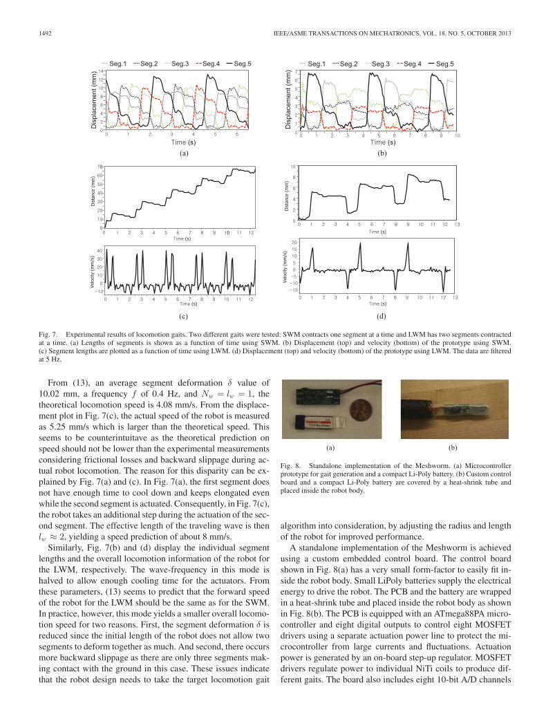
Fig. 7. Experimental results of locomotion gaits. Two different gaits were tested: SWM contracts one segment at a time and LWM has two segments contractedat a time. (a) Lengths of segments is shown as a function of time using SWM. (b) Displacement (top) and velocity (bottom) of the prototype using SWM.(c) Segment lengths are plotted as a function of time using LWM. (d) Displacement (top) and velocity (bottom) of the prototype using LWM. The data are filteredat 5 Hz.
From (13), an average segment deformation δ value of10.02 mm, a frequency f of 0.4 Hz, and Nw = lw = 1, thetheoretical locomotion speed is 4.08 mm/s. From the displace-ment plot in Fig. 7(c), the actual speed of the robot is measuredas 5.25 mm/s which is larger than the theoretical speed. Thisseems to be counterintuitave as the theoretical prediction onspeed should not be lower than the experimental measurementsconsidering frictional losses and backward slippage during ac-tual robot locomotion. The reason for this disparity can be ex-plained by Fig. 7(a) and (c). In Fig. 7(a), the first segment doesnot have enough time to cool down and keeps elongated evenwhile the second segment is actuated. Consequently, in Fig. 7(c),the robot takes an additional step during the actuation of the sec-ond segment. The effective length of the traveling wave is thenlw ≈ 2, yielding a speed prediction of about 8 mm/s.
Similarly, Fig. 7(b) and (d) display the individual segmentlengths and the overall locomotion information of the robot forthe LWM, respectively. The wave-frequency in this mode ishalved to allow enough cooling time for the actuators. Fromthese parameters, (13) seems to predict that the forward speedof the robot for the LWM should be the same as for the SWM.In practice, however, this mode yields a smaller overall locomo-tion speed for two reasons. First, the segment deformation δ isreduced since the initial length of the robot does not allow twosegments to deform together as much. And second, there occursmore backward slippage as there are only three segments mak-ing contact with the ground in this case. These issues indicatethat the robot design needs to take the target locomotion gait
(a) (b)
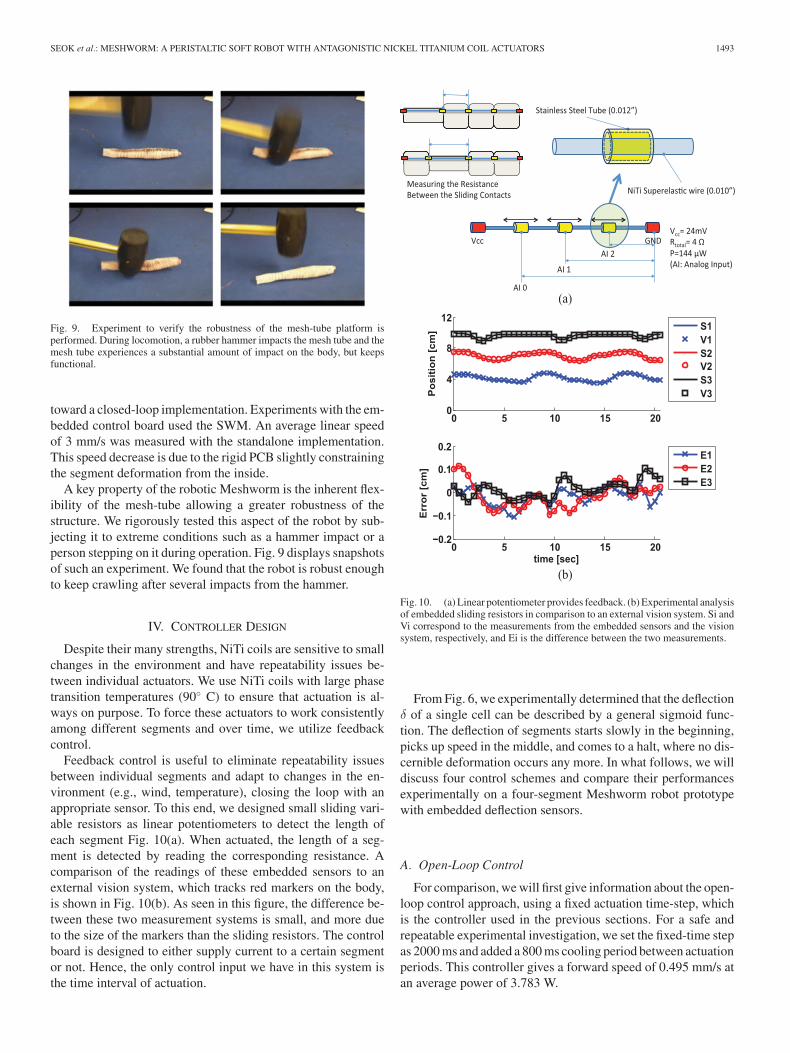
Fig. 8. Standalone implementation of the Meshworm. (a) Microcontrollerprototype for gait generation and a compact Li-Poly battery. (b) Custom controlboard and a compact Li-Poly battery are covered by a heat-shrink tube andplaced inside the robot body.
algorithm into consideration, by adjusting the radius and lengthof the robot for improved performance.
A standalone implementation of the Meshworm is achievedusing a custom embedded control board. The control boardshown in Fig. 8(a) has a very small form-factor to easily fit in-side the robot body. Small LiPoly batteries supply the electricalenergy to drive the robot. The PCB and the battery are wrappedin a heat-shrink tube and placed inside the robot body as shownin Fig. 8(b). The PCB is equipped with an ATmega88PA micro-controller and eight digital outputs to control eight MOSFETdrivers using a separate actuation power line to protect the mi-crocontroller from large currents and fluctuations. Actuationpower is generated by an on-board step-up regulator. MOSFETdrivers regulate power to individual NiTi coils to produce dif-ferent gaits. The board also includes eight 10-bit A/D channels
SEOK et al.: MESHWORM: A PERISTALTIC SOFT ROBOT WITH ANTAGONISTIC NICKEL TITANIUM COIL ACTUATORS 1493
Fig. 9. Experiment to verify the robustness of the mesh-tube platform isperformed. During locomotion, a rubber hammer impacts the mesh tube and themesh tube experiences a substantial amount of impact on the body, but keepsfunctional.
toward a closed-loop implementation. Experiments with the em-bedded control board used the SWM. An average linear speedof 3 mm/s was measured with the standalone implementation.This speed decrease is due to the rigid PCB slightly constrainingthe segment deformation from the inside.
A key property of the robotic Meshworm is the inherent flex-ibility of the mesh-tube allowing a greater robustness of thestructure. We rigorously tested this aspect of the robot by sub-jecting it to extreme conditions such as a hammer impact or aperson stepping on it during operation. Fig. 9 displays snapshotsof such an experiment. We found that the robot is robust enoughto keep crawling after several impacts from the hammer.
IV. CONTROLLER DESIGN
Despite their many strengths, NiTi coils are sensitive to smallchanges in the environment and have repeatability issues be-tween individual actuators. We use NiTi coils with large phasetransition temperatures (90◦ C) to ensure that actuation is al-ways on purpose. To force these actuators to work consistentlyamong different segments and over time, we utilize feedbackcontrol.
Feedback control is useful to eliminate repeatability issuesbetween individual segments and adapt to changes in the en-vironment (e.g., wind, temperature), closing the loop with anappropriate sensor. To this end, we designed small sliding vari-able resistors as linear potentiometers to detect the length ofeach segment Fig. 10(a). When actuated, the length of a seg-ment is detected by reading the corresponding resistance. Acomparison of the readings of these embedded sensors to anexternal vision system, which tracks red markers on the body,is shown in Fig. 10(b). As seen in this figure, the difference be-tween these two measurement systems is small, and more dueto the size of the markers than the sliding resistors. The controlboard is designed to either supply current to a certain segmentor not. Hence, the only control input we have in this system isthe time interval of actuation.
(a)
(b)
Fig. 10. (a) Linear potentiometer provides feedback. (b) Experimental analysisof embedded sliding resistors in comparison to an external vision system. Si andVi correspond to the measurements from the embedded sensors and the visionsystem, respectively, and Ei is the difference between the two measurements.
From Fig. 6, we experimentally determined that the deflectionδ of a single cell can be described by a general sigmoid func-tion. The deflection of segments starts slowly in the beginning,picks up speed in the middle, and comes to a halt, where no dis-cernible deformation occurs any more. In what follows, we willdiscuss four control schemes and compare their performancesexperimentally on a four-segment Meshworm robot prototypewith embedded deflection sensors.
A. Open-Loop Control
For comparison, we will first give information about the open-loop control approach, using a fixed actuation time-step, whichis the controller used in the previous sections. For a safe andrepeatable experimental investigation, we set the fixed-time stepas 2000 ms and added a 800 ms cooling period between actuationperiods. This controller gives a forward speed of 0.495 mm/s atan average power of 3.783 W.
1494 IEEE/ASME TRANSACTIONS ON MECHATRONICS, VOL. 18, NO. 5, OCTOBER 2013
(a)
δδ
(b) (c)
δ
δ
(d) (e)
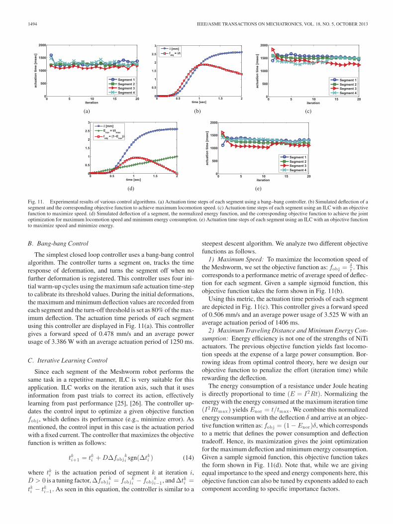
Fig. 11. Experimental results of various control algorithms. (a) Actuation time steps of each segment using a bang–bang controller. (b) Simulated deflection of asegment and the corresponding objective function to achieve maximum locomotion speed. (c) Actuation time steps of each segment using an ILC with an objectivefunction to maximize speed. (d) Simulated deflection of a segment, the normalized energy function, and the corresponding objective function to achieve the jointoptimization for maximum locomotion speed and minimum energy consumption. (e) Actuation time steps of each segment using an ILC with an objective functionto maximize speed and minimize energy.
B. Bang-bang Control
The simplest closed loop controller uses a bang-bang controlalgorithm. The controller turns a segment on, tracks the timeresponse of deformation, and turns the segment off when nofurther deformation is registered. This controller uses four ini-tial warm-up cycles using the maximum safe actuation time-stepto calibrate its threshold values. During the initial deformations,the maximum and minimum deflection values are recorded fromeach segment and the turn-off threshold is set as 80% of the max-imum deflection. The actuation time periods of each segmentusing this controller are displayed in Fig. 11(a). This controllergives a forward speed of 0.478 mm/s and an average powerusage of 3.386 W with an average actuation period of 1250 ms.
C. Iterative Learning Control
Since each segment of the Meshworm robot performs thesame task in a repetitive manner, ILC is very suitable for thisapplication. ILC works on the iteration axis, such that it usesinformation from past trials to correct its action, effectivelylearning from past performance [25], [26]. The controller up-dates the control input to optimize a given objective functionfob j , which defines its performance (e.g., minimize error). Asmentioned, the control input in this case is the actuation periodwith a fixed current. The controller that maximizes the objectivefunction is written as follows:
tki+1 = tki + DΔfob jki sgn(Δtki ) (14)
where tki is the actuation period of segment k at iteration i,D > 0 is a tuning factor, Δfob j
ki = fob j
ki − fob j
ki−1 , and Δtki =
tki − tki−1 . As seen in this equation, the controller is similar to a
steepest descent algorithm. We analyze two different objectivefunctions as follows.
1) Maximum Speed: To maximize the locomotion speed ofthe Meshworm, we set the objective function as: fob j = δ
t . Thiscorresponds to a performance metric of average speed of deflec-tion for each segment. Given a sample sigmoid function, thisobjective function takes the form shown in Fig. 11(b).
Using this metric, the actuation time periods of each segmentare depicted in Fig. 11(c). This controller gives a forward speedof 0.506 mm/s and an average power usage of 3.525 W with anaverage actuation period of 1406 ms.
2) Maximum Traveling Distance and Minimum Energy Con-sumption: Energy efficiency is not one of the strengths of NiTiactuators. The previous objective function yields fast locomo-tion speeds at the expense of a large power consumption. Bor-rowing ideas from optimal control theory, here we design ourobjective function to penalize the effort (iteration time) whilerewarding the deflection.
The energy consumption of a resistance under Joule heatingis directly proportional to time (E = I2Rt). Normalizing theenergy with the energy consumed at the maximum iteration time(I2Rtmax) yields Enor = t/tmax . We combine this normalizedenergy consumption with the deflection δ and arrive at an objec-tive function written as: fob j = (1 − Enor)δ, which correspondsto a metric that defines the power consumption and deflectiontradeoff. Hence, its maximization gives the joint optimizationfor the maximum deflection and minimum energy consumption.Given a sample sigmoid function, this objective function takesthe form shown in Fig. 11(d). Note that, while we are givingequal importance to the speed and energy components here, thisobjective function can also be tuned by exponents added to eachcomponent according to specific importance factors.
SEOK et al.: MESHWORM: A PERISTALTIC SOFT ROBOT WITH ANTAGONISTIC NICKEL TITANIUM COIL ACTUATORS 1495
TABLE IIPERFORMANCE COMPARISON OF DIFFERENT CONTROLLERS FOR THE
LOCOMOTION OF THE MESHWORM ROBOT
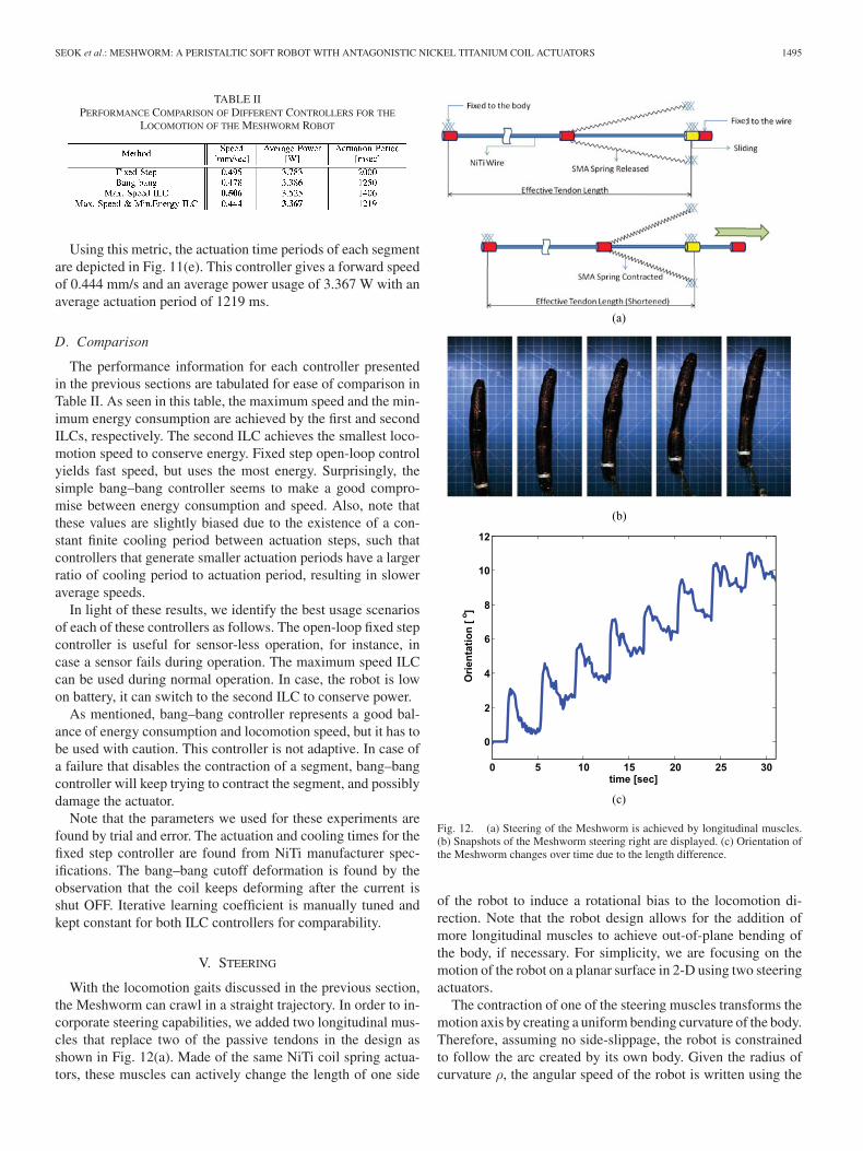
Using this metric, the actuation time periods of each segmentare depicted in Fig. 11(e). This controller gives a forward speedof 0.444 mm/s and an average power usage of 3.367 W with anaverage actuation period of 1219 ms.
D. Comparison
The performance information for each controller presentedin the previous sections are tabulated for ease of comparison inTable II. As seen in this table, the maximum speed and the min-imum energy consumption are achieved by the first and secondILCs, respectively. The second ILC achieves the smallest loco-motion speed to conserve energy. Fixed step open-loop controlyields fast speed, but uses the most energy. Surprisingly, thesimple bang–bang controller seems to make a good compro-mise between energy consumption and speed. Also, note thatthese values are slightly biased due to the existence of a con-stant finite cooling period between actuation steps, such thatcontrollers that generate smaller actuation periods have a largerratio of cooling period to actuation period, resulting in sloweraverage speeds.
In light of these results, we identify the best usage scenariosof each of these controllers as follows. The open-loop fixed stepcontroller is useful for sensor-less operation, for instance, incase a sensor fails during operation. The maximum speed ILCcan be used during normal operation. In case, the robot is lowon battery, it can switch to the second ILC to conserve power.
As mentioned, bang–bang controller represents a good bal-ance of energy consumption and locomotion speed, but it has tobe used with caution. This controller is not adaptive. In case ofa failure that disables the contraction of a segment, bang–bangcontroller will keep trying to contract the segment, and possiblydamage the actuator.
Note that the parameters we used for these experiments arefound by trial and error. The actuation and cooling times for thefixed step controller are found from NiTi manufacturer spec-ifications. The bang–bang cutoff deformation is found by theobservation that the coil keeps deforming after the current isshut OFF. Iterative learning coefficient is manually tuned andkept constant for both ILC controllers for comparability.
V. STEERING
With the locomotion gaits discussed in the previous section,the Meshworm can crawl in a straight trajectory. In order to in-corporate steering capabilities, we added two longitudinal mus-cles that replace two of the passive tendons in the design asshown in Fig. 12(a). Made of the same NiTi coil spring actua-tors, these muscles can actively change the length of one side
(a)
(b)
(c)
Fig. 12. (a) Steering of the Meshworm is achieved by longitudinal muscles.(b) Snapshots of the Meshworm steering right are displayed. (c) Orientation ofthe Meshworm changes over time due to the length difference.
of the robot to induce a rotational bias to the locomotion di-rection. Note that the robot design allows for the addition ofmore longitudinal muscles to achieve out-of-plane bending ofthe body, if necessary. For simplicity, we are focusing on themotion of the robot on a planar surface in 2-D using two steeringactuators.
The contraction of one of the steering muscles transforms themotion axis by creating a uniform bending curvature of the body.Therefore, assuming no side-slippage, the robot is constrainedto follow the arc created by its own body. Given the radius ofcurvature ρ, the angular speed of the robot is written using the
1496 IEEE/ASME TRANSACTIONS ON MECHATRONICS, VOL. 18, NO. 5, OCTOBER 2013
linear speed on the arc from (13) as
ω =v
ρ. (15)
Snapshots of a steering experiment of the Meshworm aredepicted in Fig. 12(b). As apparent from these snapshots, someside-slippage occurs due to the lack of friction normal to thebody axis, but this does not have an effect on the shape of therobot.
Using image processing of the video frames, we extract theorientation of the robot, defined as the average slope of the bodywith respect to an inertial reference frame, by color tracking redmarkers placed at each segment as seen in Fig. 12(c). We useda high-speed camera (Mikrotron MC1363) and a frame grabber(NI PCIe-1429) for the following motion tracking experimentsfor greater temporal resolution. We measure the average slopeby fitting a line to the detected marker positions. As expected,major changes in the orientation coincide with the contractionof the first segment, which is also responsible for the forwardmotion, discussed in the previous section.
VI. DISCUSSION
This study demonstrated a multisegmented soft robotic plat-form called the Meshworm, which can undergo peristaltic lo-comotion using NiTi coil spring actuators. Using the inherentantagonism of a soft braided-mesh body, which is constrainedto keep its length constant, the robot propels itself by send-ing a traveling contraction wave over its segments. A completeanalysis of the robot is presented from the theoretical modelingand experimental characterization of NiTi coil actuators to theinvestigation of different controllers for optimal performance.
An accurate model of NiTi spring actuators is developed thatincludes the change in free length of the spring due to phasetransformation. By this model, NiTi coils can be precisely de-signed according to force and displacement requirements. Thisexpands the potential for NiTi coil actuators beyond the scopeof this study. Traditionally, actuators need gears or transmis-sion mechanisms to match the impedance of the load, whichmakes the actuation system bulky. NiTi coils, however, can betuned to match the load by changing the shape and the annealingtemperature of the spring.
The mesh-tube prototype has less than ten segments, whereasits biological counterparts have close to a hundred segments.The length of each segment in the mesh-tube is longer com-pared to that of an earthworm. This prevents traveling wavesfrom forming and limits the choice of gaits. The current manu-facturing process involves manual construction and connectionsof the NiTi actuators to the mesh structure. More monolithic fab-rication methods will enable a greater number of segments ina given length, and hence smoother waves and more efficientgaits. Since the platform contains no rigid components that mayfail by external impact, this prototype can open a new space ofapplications for robust morphable robots.
With further development of a microprocessor and bat-tery with flexible form factors, this approach suggests a newparadigm of completely soft robotics that can demonstrate sig-nificant body morphing and versatile locomotion capabilities.
While this is not our focus, an entirely compliant version of oursystem can be achieved with two changes. First, using flexiblecircuit boards the rigidity of the control system can be reduced.Second, many small batteries can be used together to make aflexible electrical power system. This is possible, since batteriestechnically do not need to have a specific size or shape.
Adding sliding resistors as linear potentiometers over thelength of the robot, we achieved the ability to sense thedeflection of segments. These sensors allowed us to developclosed-loop controllers. We designed, experimentally analyzedand compared four suitable control algorithms to enable fasterspeed and lower energy consumption.
Using two longitudinal muscles on two sides of the Mesh-worm body, we incorporated steering capabilities to the mo-bile robot. With the addition ofsmultiple longitudinal musclesdistributed along the circumference, the robot can operate inthree dimensions to overcome large obstacles and traverse roughterrain.
REFERENCES
[1] W. M. K. D. Trivedi, C. D. Rahn, and I. D. Walkerca, “Soft robotics:Biological inspiration, state of the art, and future research,” Appl. BionicsBiomechanicsl, vol. 5, no. 3, pp. 99–117, 2008.
[2] C. D. Onal, X. Chen, G. M. Whitesides, and D. Rus, “Soft mobile robotswith on-board chemical pressure generation,” in Proc. Int. Symp. Robot.Res., 2011.
[3] Y. Sugiyama and S. Hirai, “Crawling and jumping of deformable softrobot,” in IEEE Int. Conf. Intell. Robots Syst., 2004, pp. 3276–3281.
[4] S. Kim, E. Hawkes, K. Cho, M. Jolda, J. Foley, and R. Wood, “Microartificial muscle fiber using NiTi spring for soft robotics,” in Proc. 2009IEEE/RSJ Int. Conf. Intell. Robots Syst., 2009, pp. 2228–2234.
[5] S. Seok, C. D. Onal, R. Wood, D. Rus, and S. Kim, “Peristaltic locomotionwith antagonistic actuators in soft robotics,” in Proc. IEEE Int. Conf.Robot. Autom., 2010, pp. 1228–1233.
[6] B. Kim, M. Lee, Y. Lee, Y. Kim, and G. Lee, “An earthworm-like microrobot using shape memory alloy actuator,” Sens. Actuators A, Phys.,vol. 125, no. 2, pp. 429–437, 2006.
[7] K. J. Quillin, “Kinematic scaling of locomotion by hydrostatic animals:Ontogeny of peristaltic crawling by the earthworm lumbricus terrestris,”J. Exp. Biol., vol. 202, pp. 661–674, 1999.
[8] T. Nakamura and T. Iwanaga, “Locomotion strategy for a peristaltic crawl-ing robot in a 2-dimensional space,” in Proc. IEEE Int. Conf. Robot.Autom., 2008, pp. 238–243.
[9] N. Saga and T. Nakamura, “Development of a peristaltic crawling robotusing magnetic fluid on the basis of the locomotion mechanism of theearthworm,” Smart Mater. Struct., vol. 13, no. 3, pp. 566–569, 2004.
[10] J. B. A. B. Slatkin and W. Grundfest, “The development of a roboticendoscope,” in Proc. IEEE Int. Conf. Intell. Robot. Syst., Piscataway,1995, pp. 162–171.
[11] E. Mangan, D. Kingsley, R. Quinn, and H. Chiel, “Development of aperistaltic endoscope,” in Proc. IEEE Int. Conf. Robot. Autom., 2002,vol. 1, pp. 347–352.
[12] B. Kim, S. Park, C. Jee, and S. Yoon, “An earthworm-like locomotivemechanism for capsule endoscopes,” in Proc. IEEE Int. Conf. Intell.Robots Syst., 2005, pp. 2997–3002.
[13] A. Menciassi, S. Gorini, G. Pernorio, and P. Dario, “A SMA actuatedartificial earthworm,” in Proc. IEEE Int. Conf. Robot. Autom., 2004, vol. 4,pp. 3282–3287.
[14] H. J. C. A. S. Boxerbaum and R. D. Quinn, “A new theory and methodsfor creating peristaltic motion in a robotic platform,” in Proc. IEEE Int.Conf. Robot. Autom., 2010, pp. 1221–1227.
[15] M. Dolce and D. Cardone, “Mechanical behaviour of shape memory alloysfor seismic applications—1. Martensite and austenite NiTi bars subjectedto torsion,” Int. J. Mech. Sci., vol. 43, pp. 2631–2656, Nov. 2001.
[16] B. Chang, J. Shaw, and M. Iadicola, “Thermodynamics of shape memoryalloy wire: Modeling, experiments, and application,” Continuum Mech.Thermodyn., vol. 18, no. 1, pp. 83–118, 2006.
[17] H. J. Lee and J. J. Lee, “Evaluation of the characteristics of a shape memoryalloy spring actuator,” Smart Mater. Struct., vol. 9, no. 6, pp. 817–823,2000.
SEOK et al.: MESHWORM: A PERISTALTIC SOFT ROBOT WITH ANTAGONISTIC NICKEL TITANIUM COIL ACTUATORS 1497
[18] Y. Dong, Z. Boming, and L. Jun, “A changeable aerofoil actuated by shapememory alloy springs,” Mater. Sci. Eng. A, vol. 485, no. 1–2, pp. 243–250,2008.
[19] K. Cho, E. Hawkes, C. Quinn, and R. Wood, “Design, fabrication andanalysis of a body-caudal fin propulsion system for a microrobotic fish,”in Proc. IEEE Int. Conf. Robot. Autom., 2008, pp. 706–711.
[20] Y. Liu, “Detwinning process and its anisotropy in shape memory alloys,”Proc. SPIE Smart Mater., vol. 4234, pp. 82–93, 2001.
[21] K. Otsuka and C. M. Wayman, Shape Memory Materials. Cambridge,U.K.: Cambridge Univ. Press, 1998.
[22] G. Chapman, “Of the movement of worms,” J. Exp. Biol., vol. 27, pp. 29–39, 1950.
[23] G. E. Newell, “The role of the coelomic fluid in the movements of earth-worms,” J. Exp. Biol., vol. 27, pp. 110–122, 1950.
[24] C. Zanotti, P. Giuliani, A. Tuissi, S. Arnaboldi, and R. Casati, “Responseof NiTi SMA wire electrically heated,” in Proc. 8th Int. Symp. MartensicTransformations, 2009, no. 06037.
[25] H.-S. Ahn, K. L. Moore, and Y. Chen, Iterative Learning Control.London, U.K.: Springer, 2007.
[26] D. A. Bristow, M. Tharayil, and A. G. Alleyne, “A survey of iterativelearning control: A learning-based method for high-performance trackingcontrol,” IEEE Control Syst. Mag., vol. 26, no. 3, pp. 96–114, Jun. 2006.
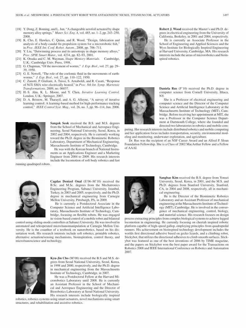
Sangok Seok received the B.S. and M.S. degreesfrom the School of Mechanical and Aerospace Engi-neering, Seoul National University, Seoul, Korea, in2002 and 2004, respectively. He is currently workingtoward the Ph.D. degree in the Biomimetic RoboticsLaboratory, Department of Mechanical Engineering,Massachusetts Institute of Technology, Cambridge.
He was with the Korean branch of National Instru-ments as an Applications Engineer and a MarketingEngineer from 2004 to 2009. His research interestsinclude the locomotion of soft body robotics and fast
running quadruped robots.
Cagdas Denizel Onal (S’06–M’10) received theB.Sc. and M.Sc. degrees from the MechatronicsEngineering Program, Sabanci University, Istanbul,Turkey, in 2003 and 2005, respectively, and the Ph.D.degree in mechanical engineering from CarnegieMellon University, Pittsburgh, PA, in 2009.
He is currently a Postdoctoral Associate in theComputer Science and Artificial Intelligence Labo-ratory, Massachusetts Institute of Technology, Cam-bridge, focusing on flexible robots. He was engagedin vision-based control of a mobile robot and bilateral
control using sliding-mode controllers at Sabanci University. He was involved inautomated and teleoperated micro/nanomanipulation at Carnegie Mellon Uni-versity. He is the coauthor of a textbook on nanorobotics, based on his dis-sertation work. His research interests include soft robotics, printable robotics,alternative actuation/sensing mechanisms, bioinspiration, control theory, andmicro/nanoscience and technology.
Kyu-Jin Cho (M’08) received the B.S and M.S. de-grees from Seoul National University, Seoul, Korea,in 1998 and 2000, respectively, and the Ph.D. degreein mechanical engineering from the MassachusettsInstitute of Technology, Cambridge, in 2007.
He was a Postdoctoral Fellow at the Harvard Mi-crorobotics Laboratory until 2008. He is currentlyan Assistant Professor in the School of Mechani-cal and Aerospace Engineering and the Director ofBiorobotics Laboratory at Seoul National University.His research interests include biologically inspired
robotics, robotics systems using smart actuators, novel mechanisms using smartstructures, and rehabilitation and assistive robotics.
Robert J. Wood received the Master’s and Ph.D. de-grees in electrical engineering from the University ofCalifornia, Berkeley, in 2001 and 2004, respectively.
He is currently an Associate Professor in theSchool of Engineering and Applied Sciences and theWyss Institute for Biologically Inspired Engineeringat Harvard University, Cambridge, MA. His researchinterests include the areas of microrobotics and bioin-spired robotics.
Daniela Rus (F’10) received the Ph.D. degree incomputer science from Cornell University, Ithaca,NY.
She is a Professor of electrical engineering andcomputer science and the Director of the ComputerScience and Artificial Intelligence Laboratory at theMassachusetts Institute of Technology (MIT), Cam-bridge. Before receiving her appointment at MIT, shewas a Professor in the Computer Science Depart-ment at Dartmouth College, where she founded anddirected two laboratories in robotics and mobile com-
puting. Her research interests include distributed robotics and mobile computingand her application focus includes transportation, security, environmental mod-eling and monitoring, underwater exploration, and agriculture.
Dr. Rus was the recipient of an NSF Career Award and an Alfred P. SloanFoundation Fellowship. She is a Class of 2002 MacArthur Fellow and a Fellowof AAAI.
Sangbae Kim received the B.S. degree from YonseiUniversity, Seoul, Korea, in 2001, and the M.S. andPh.D. degrees from Stanford University, Stanford,CA, in 2004 and 2008, respectively, all in mechani-cal engineering.
He is the Director of the Biomimetic RoboticsLaboratory and an Assistant Professor of mechanicalengineering at the Massachusetts Institute of Technol-ogy (MIT), Cambridge. He is involved in the conver-gence of mechanical engineering, control, biology,and material science. His research focuses on design
process extracting principles from complex biological systems to achieve leggedlocomotion in engineering. He currently focusing on cheetah inspired roboticplatform capable of high-speed gallop, employing principles from quadrupedalrunners. His achievement on bioinspired technology development includes theworlds first directional adhesive based on gecko lizards, and a climbing robot,Stickybot, that utilizes the directional adhesives to climb smooth surfaces. Stick-ybot was featured as one of the best inventions of 2006 by TIME magazine,and the papers on Stickybot won the best paper award for the Transactions onRobotics 2008 and IEEE International Conference on Robotics and Automation2007.