Embed Size (px)
Citation preview

STUDENT WORKBOOK Version: March 2012
Unit Code:
MEM07007C
Unit Name:
Perform milling operations
Student Name: _____________________________________________________
Student Number: ___________________________________________________
Assessment Outcome Date Teacher’s signature
Assessments requirements:Completed satisfactorily…
Assessment requirements:Not yet complete…
NOTE:Teacher & Student to sign the: “To be Completed Notification Form” - (last page of this workbook)
Instructions to students:
This workbook is a major component of the assessment for this competency, all Questions and Projects, MUST BE COMPLETED and signed off by your teacher.
It is the student’s responsibility to complete the Assessment Requirements, listed in this workbook and to ensure that teachers progressively sign off requirements as they are completed. (Teachers must not sign off work they have not witnessed completed)
When completed the “Assessment Outcome” (above) is to be signed by your teacher.
This workbook is to be retained by the student as their record of the completion of this competency.


MEM07007C Perform milling operationsPage 3
Compulsory Assessment Requirements
For MEM07007C
Assessment/Project Completion Date
Teacher’s signature
“Student Safety Requirements for Workshops” – Form Signed
1 – Overarm machined to specifications
2 – Base Plate machined to specifications
3 – Pinion Gear machined to specifications
4 – Rack machined to specifications
5 – Assignment completed satisfactorily
6 – Quality control task - Overarm measured
7 – Final Examination
SkillsTech – MEM07007C Student Workbook – Version March 2012

MEM07007C Perform milling operationsPage 4
ContentsSection 1: Unit of Competency........................................................6Competency Descriptor.................................................................................................................................................... 6
Competency Unit Resources............................................................................................................................................ 7
Assessment Strategies..................................................................................................................................................... 8
Lesson Schedule.............................................................................................................................................................. 9
Section 2: Assessment Tasks.......................................................10Assessment Task No1.................................................................................................................................................... 10
Assessment Task No2.................................................................................................................................................... 10
Assessment Task No3.................................................................................................................................................... 10
Assessment Task No4.................................................................................................................................................... 10
Assessment Task No5.................................................................................................................................................... 10
Assessment Task No6.................................................................................................................................................... 10
Assessment Task No7.................................................................................................................................................... 10
Assessment Task No8.................................................................................................................................................... 10
Section 3: Observe Safety Precautions........................................11Workshop Safety............................................................................................................................................................ 11
Review Questions – Observe Safety Precautions..........................................................................................................21
Section 4: Determine Job Requirements......................................23Introduction..................................................................................................................................................................... 23
Instructions and specifications........................................................................................................................................ 24
Sequence of Operations................................................................................................................................................. 25
Tooling............................................................................................................................................................................ 27
Cutting fluids................................................................................................................................................................... 40
Cutting Parameters......................................................................................................................................................... 43
Review Questions – Determine Job Requirements........................................................................................................49
Section 5 – Perform milling operations...........................................60Setting up work holding devices..................................................................................................................................... 60
Types of Vice.................................................................................................................................................................. 62
Review Questions – Setting up workholding devices......................................................................................................77
Setting up a workpiece................................................................................................................................................... 79
Setting cutters................................................................................................................................................................. 83
Mounting and centralising gear cutters........................................................................................................................... 84
Centralising the cutter..................................................................................................................................................... 85
Dividing Heads................................................................................................................................................................ 86
Calculations for Indexing................................................................................................................................................ 89
Review Questions – Setting workpieces, Cutters, Indexing............................................................................................94
Types of milling operation............................................................................................................................................... 99
Milling machine attachments........................................................................................................................................ 104
Review Questions – Milling operations , Milling machine attachments.........................................................................108
Section 6 – Check components for conformance with specificiations111
SkillsTech – MEM07007C Student Workbook – Version March 2012
MEM07007C Perform milling operationsPage 5
Introduction................................................................................................................................................................... 111
Direct measurement tools............................................................................................................................................. 111
Comparative measurement tools.................................................................................................................................. 120
Recording size conformance........................................................................................................................................ 127
Review Questions – Check components for conformance...........................................................................................128
Section 7 – Drawing appendix......................................................130Arbor Press - Sheet 1................................................................................................................................................... 130
Arbor Press – Sheet 2.................................................................................................................................................. 131
Arbor Press – Sheet 3.................................................................................................................................................. 132
Arbor Press – Sheet 4.................................................................................................................................................. 133
Arbor Press – Sheet 5.................................................................................................................................................. 134
Section 8 - Risk Management.....................................................135
SkillsTech – MEM07007C Student Workbook – Version March 2012
MEM07007C Perform milling operationsPage 6
Section 1: Unit of Competency
Competency Descriptor
Unit descriptor This unit covers performing milling operations on a range of milling machines.
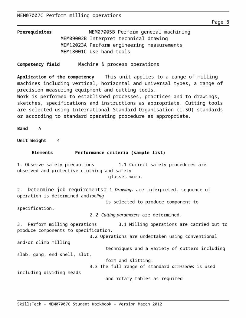
Prerequisites MEM07005B Perform general machiningMEM09002B Interpret technical drawingMEM12023A Perform engineering measurementsMEM18001C Use hand tools
Competency field Machine & process operations
Application of the competency This unit applies to a range of milling machines including vertical, horizontal and universal types, a range of precision measuring equipment and cutting tools.Work is performed to established processes, practices and to drawings, sketches, specifications and instructions as appropriate. Cutting tools are selected using International Standard Organisation (I.SO) standards or according to standard operating procedure as appropriate.
Band A
Unit Weight 4
Elements Performance criteria (sample list)
1. Observe safety precautions 1.1 Correct safety procedures are observed and protective clothing and safety glasses worn.
2. Determine job requirements 2.1 Drawings are interpreted, sequence of operation is determined and tooling is selected to produce component to specification.2.2 Cutting parameters are determined.
3. Perform milling operations 3.1 Milling operations are carried out to produce components to specification.3.2 Operations are undertaken using conventional and/or climb milling techniques and a variety of cutters including slab, gang, end shell, slot, form and slitting.3.3 The full range of standard accessories is used including dividing heads and rotary tables as required
SkillsTech – MEM07007C Student Workbook – Version March 2012
MEM07007C Perform milling operationsPage 7
4. Check components for conformance 4.1 Components are checked for conformance to specification using with specifications appropriate techniques, tools and equipment
SkillsTech – MEM07007C Student Workbook – Version March 2012
MEM07007C Perform milling operationsPage 8
Competency Unit Resources
Prescribed Text:
No text book has been set for this competency.
However, there are many books that cover "Fitting and Machining" in the Institute Library. You are able to access these at any time.
Reference Resources:
Fitting and Machining, Culley, Ron ED., 1996, TAFE Publications, Collingwood, Vic
Principals of Machine Maintenance, Dick Jeffrey. (Yeronga Lib. No. - TJ 1040 .J43 1991)
Basic Training Manual: Workshop Safety, 1999, Australian Training Products Ltd, Melbourne
Basic Training Manual: Hand and Power Tools, 1999, Australian Training Products Ltd, Melbourne
Machine Shop Technology Vol 1, Maskiell & Galbraith, 1984, McGraw-Hill Book Company
Engineering Drawing Handbook, The Institution of Engineers Australia.. (Lib. No. - T 357.E53 1993)
Australian Standards: AS1100 - Technical drawingAS1101 – Graphical symbols for general engineeringAS1654 – Limits and fits for engineeringAS2536 – Surface Texture
SkillsTech – MEM07007C Student Workbook – Version March 2012

MEM07007C Perform milling operationsPage 9
Assessment Strategies
The following table indicates the strategies used to assess the underpinning knowledge and first practice deemed necessary to be successful in the “Off the Job” component of this CSU.To be deemed competent, students must satisfy the criteria stipulated by the Metals & Engineering National Training Package assessment in the workplace as well as the “Off the Job” component.
Element Criteria
Theory Examination Practical Exercises Assignment Presentation
1 2 3 4
Students will complete and submit for feedback all nominated exercises from the supplied resource book.All exercises must be completed and will include application of learned techniques, skills and practices listed for this Competency Standard Unit.
Method of assessment
Assessors should gather a range of evidence that is valid, sufficient, current and authentic. Evidence can be gathered through a variety of ways including direct observation, supervisor’s reports, project work, samples and questioning. Questioning techniques should not require language, literacy and numeracy skills beyond those required in this unit of competency. The candidate must have access to all tools, equipment, materials and documentation required. The candidate must be permitted to refer to any relevant workplace procedures, product and manufacturing specifications, codes, standards, manuals and reference materials.
SkillsTech – MEM07007C Student Workbook – Version March 2012
MEM07007C Perform milling operationsPage 10
SkillsTech – MEM07007C Student Workbook – Version March 2012

MEM07007C Perform milling operationsPage 11
Lesson Schedule
The following lesson schedule is suggested for the delivery of content by teachers and also to allow students time to display evidence of the underpinning knowledge they have gained and practical application required MEM07007C
Session Topic Resource
Lesson 1(4 hours)
Introduction to Competency: Check for “new” students & perform orientation if required; Discuss course activities, assessment procedures (theory & practical);Milling machines in general, SAFETY and machine maintenance requirements (Section 1 of workbook)Operational planning for milling (Section 7 of workbook)Indexing theory and calculation exercises (Section 5 of workbook)Basic gear calculations for Rack and Pinion; OD, Depth of Cut, Transverse PitchGroup exercise – Setting up machine to cut pinion. Teacher to explain procedures while students set up machine. Students to take notes for Assignment detailing all set up procedures and calculations needed.** Assignment to be submitted by third day for preliminary assessment **
07007CStudent
Workbook
Lesson 2(4 hours)
Theory Delivery: Cutters, mounting cutters, cutting parameters, work holding, operations (Sections 2,3,4,6 of workbook) accurate setting up vicesTeacher to discuss each of the milling job requirements in detailStudents to set up milling machines, two set up for facing ends of (column spindle) Base and Overarm, One machine set up for cutting pinion gear. One machine with rotary table for Base. Vertical mill for Base holes,Two machines set up for end slot on Overarm. (column spindle). Two for blocking the Rack (vertical spindle) Students to pair up where necessary.
07007CStudent
Workbook
Lesson 3(4 hours)
Teacher to Discuss need for toolmakers button on Overarm (stepped bore end) lathe set up with fixture.Students to continue with PRACTICAL work
07007CStudent
Workbook
Lesson 4(4 hours)
Students to continue with PRACTICAL workStudents to submit assignment no later than beginning of lesson 6
07007CStudent
Workbook
Lesson 5(4 hours)
Teacher to assess assignments and return for rework if necessaryPractical Work: Student to continue with practical workAssignment Work: Students to rework assignment if necessary and re-submit
07007CStudent
Workbook
Lesson 6(4 hours)
Practical Work: Student to continue with practical workAssignment Work: Students to rework assignment if necessary and re-submit
07007CStudent
Workbook
Lesson 7(4 hours)
Practical Work: Student to continue with practical workAssignment Work: Students to rework assignment if necessary and re-submit
07007CStudent
Workbook
Lesson 8(4 hours)
Practical Work: Student to continue with practical workAssignment Work: Students to rework assignment if necessary and re-submit
07007CStudent
Workbook
Lesson 9(4 hours)
Summative theory assessment Review of Assessment Re-Assessment where appropriate
07007CStudent
Workbook
SkillsTech – MEM07007C Student Workbook – Version March 2012

MEM07007C Perform milling operationsPage 12
Lesson 10(4 hours)
Practical Work: Students to complete practical assessment tasks, Complete theory retests where applicable assessment.
07007CStudent
Workbook
Section 2: Assessment Tasks
Assessment Task No1
Students are to complete the milling operations required for the OVERARM (item 3) as per the specifications.
Assessment Task No2
Students are to complete the milling operations required for the BASE PLATE (item 1) as per the specifications.
Assessment Task No3
Students are to complete the milling operations required for the END PLATE (item 12) as per the specifications.
Assessment Task No4
Students are to complete the milling operations required for the PINION (item 5) as per the specifications.
Assessment Task No5
Students are to complete the milling operations required for the RACK (item 4) as per the specifications.
Assessment Task No6
Students are to complete the written assignment as per hand out Instruction Sheet. The assignment must be submitted for preliminary assessment no later than the end of the third last lesson.
SkillsTech – MEM07007C Student Workbook – Version March 2012

MEM07007C Perform milling operationsPage 13
Assessment Task No7
Students are to complete the Quality Assurance exercise of measuring specified features of the Overarm as detailed on page 127 of this workbook.
Assessment Task No8
Students are to complete theory assessment
SkillsTech – MEM07007C Student Workbook – Version March 2012

MEM07007C Perform milling operationsPage 14
Section 3: Observe Safety Precautions
This section contributes to the underpinning knowledge required for the successful completion of the following criteria:
1.1 – Correct safety procedures observed and protective clothing and safety glasses worn
Workshop Safety
All machine tools are dangerous if used improperly or carelessly. Working safely is the first thing the user or operator should learn because the safe way is the correct way. A person learning to operate machine tools must first learn the safety regulations and precautions for each tool or machine. Most accidents are caused by not following prescribed procedures. Develop safe work habits rather than suffer the consequences of an accident.
The following topics will be covered in this section:
Eye protection Foot protection Clothing Noise Dust & fumes Lifting procedures Electrical safety General safety instruction
Eye protection
Using eye protection in the machine or fitting shops is the most important safety rule that should be followed at all times. Metal chips and shavings (called swarf) can fly at great speeds and distances from cutting tools or machinery and have caused serious eye injuries. Safety glasses must be worn when working with either machinery or hand cutting tools, since most hand cutting tools are made of hardened steel and can break or shatter when used improperly.
There are many different types of safety glasses available from manufacturers, however, the ones that offer the best protection are the safety glasses with side shields. Safety goggles should be worn over prescription glasses unless they are safety prescription glasses.
You should always follow the instructions indicated by relevant signs in the workshops in regard to the wearing of eye protection
SkillsTech – MEM07007C Student Workbook – Version March 2012
MEM07007C Perform milling operationsPage 15
Foot protection
The floors in a machine shop or fitting shop are often covered with razor-sharp metal chips called swarf) of various sizes and shapes, and heavy bar stock or machine accessories may be dropped on the feet. In the fitting shop, accidentally dropping of tools or components may happen. Therefore, safety shoes or boots that comply to the relevant Australian Standard must be worn at all times.
Safety shoes and boots are available in many brands and styles. These have a steel plate (or other impact resistant type of material) located over the toe and are designed to resist impact. Some safety shoes also have an instep guard.
Thongs and Sandals are NOT acceptable items of footwear in a workshop:
Enclosed leather shoes or boots are acceptable when in an office or class room situation only.
Clothing
When working in the workshops you are required to wear appropriate clothing such as overalls, or, trousers and shirt that may have either long or short sleeves. Shirts must be correctly tucked into trousers at all times. If you are wearing a long sleeved shirt, the sleeves must be buttoned, or correctly rolled up so as not to be able to be caught in machinery.
The following are NOT acceptable:
Tee-shirts Clothing that is either torn or badly frayed Shirts not tucked in or properly secured in trousers
Noise
Noise hazards are very common in the machine and fitting shops. High intensity noise from a variety of sources such as portable grinders (especially air driven equipment) can cause permanent loss of hearing. Although noise hazards cannot always be eliminated, hearing loss is avoidable through the use of ear muffs, ear plugs, or both. Where appropriate, hearing protection is provided in the form of ear muffs or ear plugs. When using ear plugs it is your responsibility to ensure that they are correctly fitted. If in doubt how to correctly fit them, ask!
SkillsTech – MEM07007C Student Workbook – Version March 2012

MEM07007C Perform milling operationsPage 16
Dust and fumes
Grinding dust from abrasive wheels is made up of extremely fine particles of the metal being ground and from the wheel itself.. Some grinding machines are equipped with vacuum dust collectors, or use a coolant to cool and lubricate the grinding process that has the benefit of collecting most of the dust from being dispersed into the air.
When operating a grinder without a vacuum collection system ( or using a portable grinder) where a dust hazard is present, wear an approved respirator or dust mask suitable for the nature of the task to avoid inhaling the dust. Whenever possible, use coolant when grinding. This will aid in dust control. Grinding dust can be very dangerous to your health, especially from a variety of metals or synthetic materials. These materials require careful control of grinding dust.
Metals such as zinc and cadmium give off toxic fumes when heated above their boiling point. Inhaling these fumes may cause temporary sickness, or death. The fumes produced from lead and mercury are very harmful, as their effect is cumulative in the body and can cause irreversible damage. When unsure of the materials being machined, ASK about appropriate safety measures.
Lifting procedures
When working in the machine or fitting shops, it is a part of daily routine to use manual handling. This involves bar stock, the fitting of machine accessories, or the handling equipment for repair, parts and components. Using improper lifting procedures or techniques may result in a permanent back injury or an accident. Back injury can be avoided if the correct lifting procedures are followed. When lifting heavy or large objects, get some assistance or use a hoist or forklift.
Objects within your ability can be lifted safely as long as the following procedures are followed:
Keep your back straight.
Squat down, bending at the knees.
Use the leg muscles to do the work and lift slowly. Do not bend over the load as this will put excessive strain on your spine.
Carry the object where it is comfortable, and pay close attention to where you are walking and objects around you.
When placing the object back on the floor, use the same procedures as when it was lifted.
SkillsTech – MEM07007C Student Workbook – Version March 2012
MEM07007C Perform milling operationsPage 17
Electrical safety
In the machine shop, exposure to electrical hazard will be minimal unless you, the operator, become involved with machine repair. The machinist or fitter/turner using the machine in a workshop is mostly concerned with the on and off switch and sometimes the machine isolating switch on machines such as a lathes, milling, drilling and grinding machines.
However, if major adjustments or repairs must be made, the power source should be isolated. If the machine is wired permanently, the circuit breaker or, if provided, the machine isolating switch, should be switched off and tagged with an appropriate approved isolation tag in accordance with site operating procedures. It is not necessary to isolate or disconnect the power supply for routine adjustments such as changing machine feeds or speeds. However, if you do need to change a machine accessory such as a chuck on a lathe, or the arbor in a milling machine, it is good practice to turn off the isolating switch to make sure that the machine cannot be accidentally started.
When using portable electrical tools, you should check to ensure it is in a safe operating condition. Some things that need to be checked include ensuring a current electrical inspection tag is attached and that the leads and plugs are in a good safe working condition.
The workshops are fitted with an Emergency Stop system. This is for use in an emergency where it is necessary in the event of an accident to stop electrically driven machinery. In most cases, it will stop ALL machinery in the workshop, not just the machine involved in an accident.
General safety instructions
When you are in the workshops, it is your obligation under the Workplace Health and Safety Act to follow all directions and instructions.
If an emergency situation arises, summon your teacher immediately.
Emergency Evacuation
The emergency evacuation procedure is posted in each workshop. Make sure you are familiar with the evacuation procedure.
Training Sessions
No student/trainee is to commence using any machinery, equipment or perform work unless a trainer/ teacher/tutor is present.
SkillsTech – MEM07007C Student Workbook – Version March 2012
MEM07007C Perform milling operationsPage 18
Safety Equipment
Fire extinguishers of an appropriate type are fitted in relevant locations in each workshop. These are for use in an emergency only.
Hair Protection
Where necessary, appropriate hair protection must be worn when a student has hair of such a length that in the opinion of the teacher/tutor, the risk of injury is unacceptable. In such cases, the teacher/tutor will direct a student to wear appropriate hair protection. The teacher/tutors decision is final. It is your responsibility to provide the appropriate protection as directed
Operation of Machinery
Do not attempt to operate any machine that you are unfamiliar with or for which you have not received instruction in the safe use of. Make sure all guards are in place and used correctly in accordance with manufacturer’s instructions or Standard Operating Procedures.
Personal Protective Equipment
Safety glasses must be worn at all times in the workshop unless directed otherwise by your teacher/tutor. It is your responsibility to supply safety glasses. Safety shoes or boots must be worn at all times.
Students without the appropriate Personal Protective Equipment or not meeting the relevant standard of dress will not be allowed to commence, or to participate in training sessions where missing protective items are compulsory.
Housekeeping
It is your responsibility to return all tools and equipment to the correct locations at the end of a training session. Damaged or broken tools should be appropriately identified and reported to your teacher/tutor. All machinery should be cleaned and lubricated using appropriate safety procedures, especially for the removal of swarf etc. All swarf, discarded materials and rubbish are to be placed in the appropriate bins provided. All machinery is to be turned off. All coolant spills are your responsibility to clean up.
SkillsTech – MEM07007C Student Workbook – Version March 2012
MEM07007C Perform milling operationsPage 19
Machine Safety
The operator is responsible for taking all the necessary steps to ensure that the best and safest use is made of a machine.
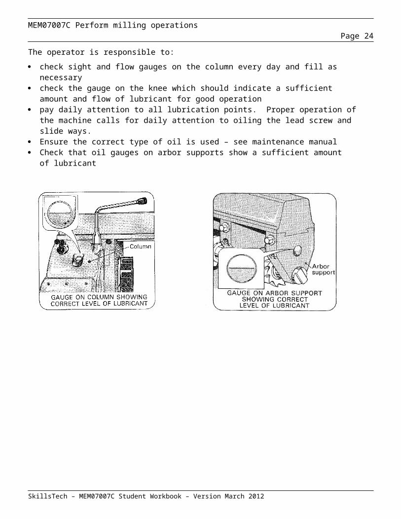
Care of machinesThe operator is responsible to:
check sight and flow gauges on the column every day and fill as necessary check the gauge on the knee which should indicate a sufficient amount and flow of lubricant for
good operation pay daily attention to all lubrication points. Proper operation of the machine calls for daily attention
to oiling the lead screw and slide ways. Ensure the correct type of oil is used – see maintenance manual Check that oil gauges on arbor supports show a sufficient amount of lubricant
SkillsTech – MEM07007C Student Workbook – Version March 2012
MEM07007C Perform milling operationsPage 20
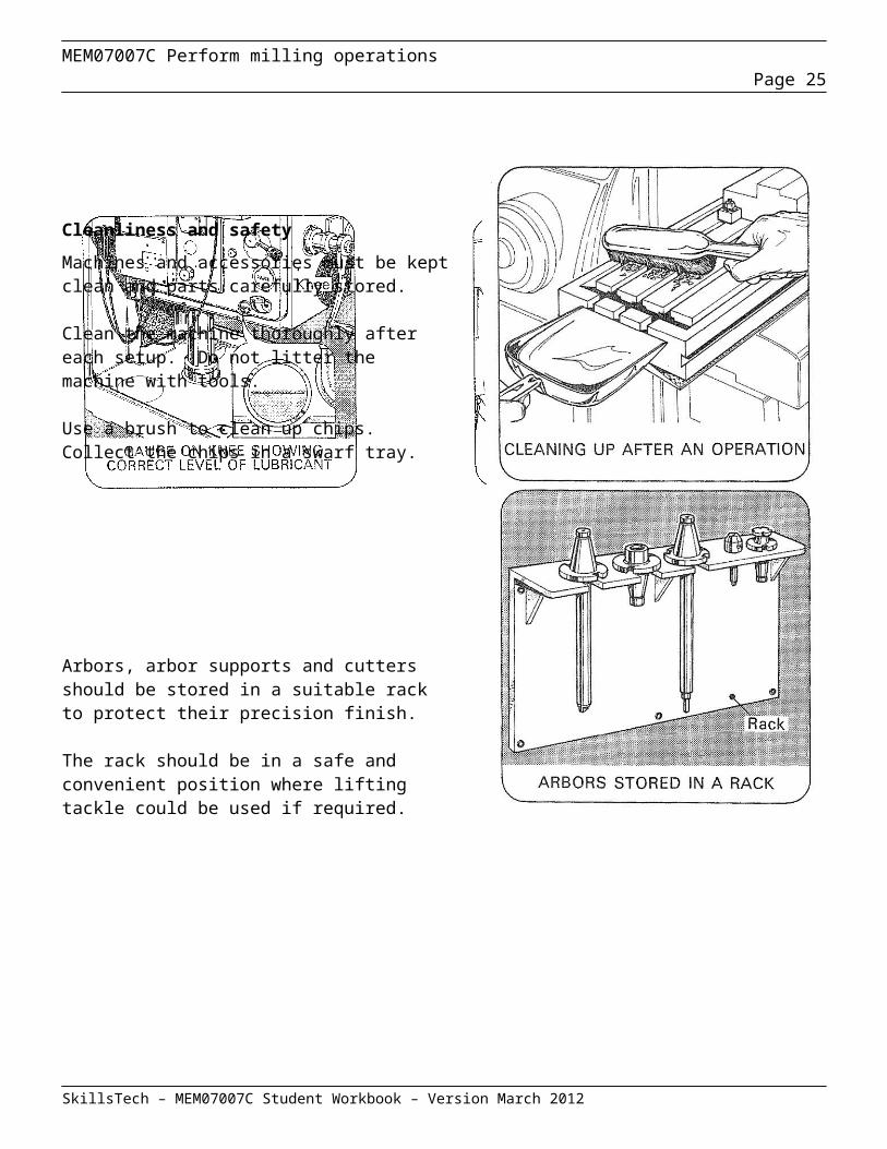
Cleanliness and safety
Machines and accessories must be kept clean and parts carefully stored.
Clean the machine thoroughly after each setup. Do not litter the machine with tools.
Use a brush to clean up chips. Collect the chips in a swarf tray.
Arbors, arbor supports and cutters should be stored in a suitable rack to protect their precision finish.
The rack should be in a safe and convenient position where lifting tackle could be used if required.
SkillsTech – MEM07007C Student Workbook – Version March 2012
MEM07007C Perform milling operationsPage 21
Care of cutters
Cutters must be handled carefully and stored safely. Cutters mounted on wooden pegs can be safely kept where they are out of the way yet easily accessible when needed.
Never pile cutters haphazardly on a table or among other metal tools. A cutter if dropped is likely to chip or crack a tooth.
Machine work should be properly set up.
Work must be set up so that holding fixtures will clear the cutter. Work should be mounted securely.If the holding fixture is proud of the workpiece the cutter will strike the hardened edge of the holding fixture and a tooth may be broken.
During a cutting operation a missing tooth causes twice the workload on the next tooth. This affects the finish.
All teeth should be ground to the same height.
When all teeth are the same height the work of cutting is shared and wear is evenly distributed.
High and low teeth throw an excessive amount of work on the high teeth.
When it is necessary to check height of teeth:
switch off machine disengage machine rotate cutter anticlockwise by hand.
SkillsTech – MEM07007C Student Workbook – Version March 2012
MEM07007C Perform milling operationsPage 22
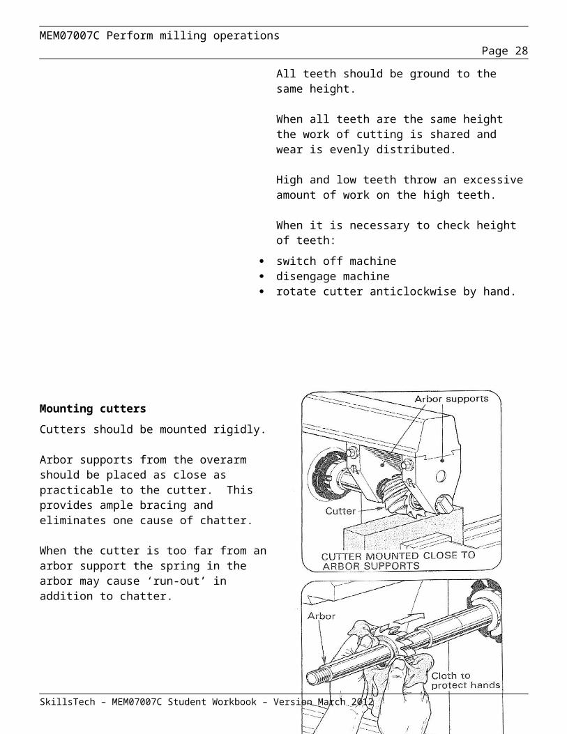
Mounting cutters
Cutters should be mounted rigidly.
Arbor supports from the overarm should be placed as close as practicable to the cutter. This provides ample bracing and eliminates one cause of chatter.
When the cutter is too far from an arbor support the spring in the arbor may cause ‘run-out’ in addition to chatter.
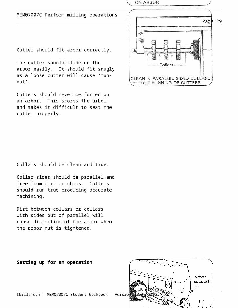
Cutter should fit arbor correctly.
The cutter should slide on the arbor easily. It should fit snugly as a loose cutter will cause ‘run-out’.
Cutters should never be forced on an arbor. This scores the arbor and makes it difficult to seat the cutter properly.
Collars should be clean and true.
Collar sides should be parallel and free from dirt or chips. Cutters should run true producing accurate machining.
Dirt between collars or collars with sides out of parallel will cause distortion of the arbor when the arbor nut is tightened.
SkillsTech – MEM07007C Student Workbook – Version March 2012

MEM07007C Perform milling operationsPage 23
Setting up for an operation
Switch off the machine before setting up for an operation.
Support arbor when tightening arbor nut.
Place the arbor support in position properly to support the arbor before tightening the end nut.
Tightening the arbor nut without the arbor support may spring the arbor.
Clamp work correctly.
Place the clamp stud close to the workpiece for correct effective holding.
It is wrong to place the clamp stud close to the jack because then the jack is clamped not the workpiece.
Support work where necessary.
When held in a vice shallow workpieces should be set on parallels wherever possible.
Work held in a vice without proper support underneath is likely to move.
SkillsTech – MEM07007C Student Workbook – Version March 2012
MEM07007C Perform milling operationsPage 24
Review Questions – Observe Safety Precautions
Question 1a. What is the minimum eye protection for this TAFE workshop?b. When is the minimum eye protection applied?c. What additional protection is needed if you are wearing standard prescription glasses?
___________________________________________________________________________________
___________________________________________________________________________________
___________________________________________________________________________________
Question 2What items of footwear are NOT acceptable in the machine shop?
___________________________________________________________________________________
Question 3List the minimum work clothing acceptable in the TAFE workshop.
__________________________________________________________________________________
Question 4Why is it essential that shirts be tucked in and badly worn or frayed clothing NOT be worn when using machinery?
___________________________________________________________________________________
___________________________________________________________________________________
SkillsTech – MEM07007C Student Workbook – Version March 2012
MEM07007C Perform milling operationsPage 25
Question 5Which two (2) metals give off toxic fumes when grinding?
_______________________________________________________________________________
Question 6If there is noise hazard present, what types of hearing protection can you use and what are your responsibilities?
____________________________________________________________________________________
____________________________________________________________________________________
Question 7Under what circumstances should you wear dust protection in the machine shop?
_____________________________________________________________________________________
_____________________________________________________________________________________
Question 8List the three (3) basic lifting procedural steps that are to be used to avoid back injury if the object to be lifted is within your capacity to perform a manual lift.
a) _________________________________________________________________________________
b) _________________________________________________________________________________
c) _________________________________________________________________________________
Question 9What is the purpose of the emergency stop system provided in the TAFE workshop?
______________________________________________________________________________________
Question 10 Why is it advisable to wear a cap when carrying out machining operations?
SkillsTech – MEM07007C Student Workbook – Version March 2012

MEM07007C Perform milling operationsPage 26
___________________________________________________________________________________
___________________________________________________________________________________
Section 4: Determine Job Requirements
This section contributes to the underpinning knowledge required for the successful completion of the following criteria:
2.1 - Drawings interpreted, the sequence of operation determined and tooling is selected to produce component to specification.2.2 - Speeds Cutting parameters are determined.
Introduction
Before any machining operation, it is important to spend some time planning for the work required. The decisions made during the planning process should be recorded. This is usually done on a Planning Sheet, a sample of which is displayed on page 23. The use of planning sheets in a machine shop has the following advantages.
the highest standards of quality and accuracy will be met. non-essential machining may be reduced. required tooling can be identified prior to commencing work. the time taken can be controlled so that completion occurs within the stated timeline the cost of production will be as low as possible.
The following issues will need to be considered as part of the planning process as they will all influence the effectiveness and efficiency of final outcome of the machining that is to be done.
Instructions and specifications Sequence of operations Tooling Surface texture Work holding
SkillsTech – MEM07007C Student Workbook – Version March 2012

MEM07007C Perform milling operationsPage 27
SkillsTech – MEM07007C Student Workbook – Version March 2012
MEM07007C Perform milling operationsPage 28
Instructions and specifications
In order to plan any machining operations it is essential that all relevant drawings, instructions, and specifications are obtained. Where these are obtained will be dependent on whether you have a formal process or an informal process in your workplace.
Listed below are typical information requirements to enable machining of a component. (a) the type of material being used.(b) the shape of the item.(c) the features which require machining.(d) the dimensions of all machined features.(e) the accuracy required.
In large organisations, a formal process is most likely to be used. A quality procedure detailing the process steps to obtain relevant information and locations of files may be use.
Drawings and specifications may be available from files held in specific locations such as a drawing and design office, or, alternatively, these may be controlled and issued by your workshop manager or supervisor when you are assigned a turning or machining job.
In some instances, where batches of items are to be produced, or regular routine operations are undertaken in maintenance and repair, a Standard Operating Procedure (S.O.P.) may be required. You will need to be aware of their use, purpose and location in your workplace. A standard operating procedure details the best methods and required specification for doing the task.
In some instances, you may have to refer to Australian Standards for specific information to assist you in interpreting drawings or specifications.
On some occasions, detail drawings, specifications or even simple sketches, may be provided by the customer.
Your workplace may not have Quality Procedures or even (SOP’s), and be limited in the range of equipment available. This will influence the way in which you can or cannot complete your job.
It is important that all necessary sources of information required are obtained to assist you in determining exactly what you have to do.
SkillsTech – MEM07007C Student Workbook – Version March 2012
MEM07007C Perform milling operationsPage 29
Sequence of Operations
When deciding on the sequence of operations it is important to understand the function of each feature of the component. The following definitions need to be understood for successful sequence planning to occur.
Definitions
Of the total number of machined surfaces indicated on a component some will be mating with surfaces on other components as part of an assembly and will therefore have a key function to perform. Such surfaces as are in close contact with other surfaces on other components are known as ‘functional surfaces’.
A ‘datum surface’ is one from which other features are measured and is marked as such on the drawing using the standard symbol of a blacked in triangle with its base on a projection line from the surface.
A ‘functional dimension’ will either locate or give the size of a functional surface or feature. Functional dimensions are frequently toleranced and may also have finish requirements which is an indication of their importance.
Machine selection
The limitations of the existing workshop equipment must be considered in terms of all the operations necessary to produce the component. It may be that alternative methods have to be considered, for example, if a milling operation cannot meet the required surface finish because the available mills are incapable of achieving this due to wear then surface grinding may be substituted or added.
Deciding on the sequence of operations
The following points should be considered when planning a sequence of operations.
select the most important functional surface to act as a datum for other surfaces and machine it first. Complete all roughing out before any finishing (to minimize distortion) carry out as many operations as possible from the one set up to ensure accuracy. work holding methods for each operation. where any clamping devices are used, they should hold the work without distorting it. will the plan devised produce the degree of accuracy required. are the available machines capable of performing the operations efficiently and
economically.
SkillsTech – MEM07007C Student Workbook – Version March 2012

MEM07007C Perform milling operationsPage 30
This information and other details can be listed on a Workshop Planning Sheet such as the one shown on the following page.
SkillsTech – MEM07007C Student Workbook – Version March 2012

MEM07007C Perform milling operationsPage 31
OPERATIONS SHEET
PART NAME: _____________________________________ PART NO. ______________ QUANTITY: ________________
DATE: ____________________ BY: ____________________________________ SH _______ OF _________
OP No. DESCRIPTION TOOL CODE
INSERT CODE WORK HOLDING SPEED FEED
SkillsTech – MEM07007C Student Workbook – Version March 2012
MEM07007C Perform milling operationsPage 32
Tooling
Milling cutter materials
The most common materials used for the manufacture of milling cutters are:
carbon steel high speed steel sintered carbides or tungsten carbide ceramics industrial diamonds.
Carbon Steel: Carbon steels are used to produce cheap relatively short life cutters which are suitable for machining non-ferrous material. Low cutting speeds and feed rates are necessary to avoid overheating and consequent reduction of hardness. Cutting fluid must be used during cutting operations.
High speed steel : The composition of high speed steel may be varied at manufacture to produce a wide range of alloys, each suitable for a particular range of cutting speed rates. The wear, shock resistance and hardness characteristics of these alloys make them suitable for use in high speed milling operations. Standard high speed milling cutters are usually produced to the specification 18 – 4 – 1. This means the steel includes 18% tungsten, 4% chromium and 1% vanadium in its composition.
Sintered carbides : Tungsten carbide, cobalt and tantalum carbide are fused at high temperatures in moulds to form accurately shaped cutting tools. The composition may be varied at manufacture to produce materials with a wide range of hardness, toughness and wear resisting properties. Because sintered carbides are expensive to produce they are used only as cutting tips or edges fitted to low grade steel bodies. The tips are fixed to the cutter body by clamping or brazing.
Ceramics : Ceramic cutting tools rank in hardness between sintered carbides and diamonds. They are made from aluminium, silicon or magnesium oxides, either singly or in combination in a process similar to that used for making sintered carbides. Ceramics are produced in the form of inserts that are clamped to the cutter body. They have high heat and wear resistance but are very brittle. Ceramics tipped milling cutters are used for light, high speed finishing cuts.
Diamonds : Industrial grade diamonds that are mounted in steel shanks and lapped to a cutting edge are sometimes used for precision finishing cuts in boring operations. Light cuts are made at high speed with a fine feed rate. These tools have a high wear resistance and are capable of manufacturing accuracy in repetition work.
SkillsTech – MEM07007C Student Workbook – Version March 2012

MEM07007C Perform milling operationsPage 33
Tooth geometry
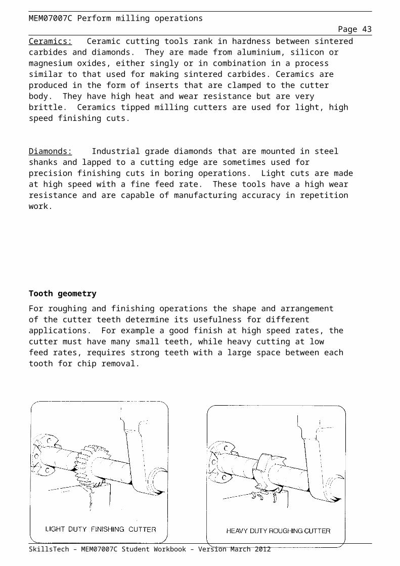
For roughing and finishing operations the shape and arrangement of the cutter teeth determine its usefulness for different applications. For example a good finish at high speed rates, the cutter must have many small teeth, while heavy cutting at low feed rates, requires strong teeth with a large space between each tooth for chip removal.
The angle formed by the tooth in relation to the axis of the cutter is called the helix angle, and is important to the cutting process.
For narrow cutters, where the loading on each tooth is small, this angle is usually zero because the teeth are straight. Wide cutters with straight teeth would be subject to heavy shock loads as each tooth engaged the workpiece. This would cause chattering and could damage the cutter or the milling machine.
Wide cutters are therefore given a substantial helix angle so that two or more teeth are always engaged with the workpiece during the milling operation. This results in a continuous loading on the cutter and produces a better finish.
Helical tooth cutter Straight tooth cutter
SkillsTech – MEM07007C Student Workbook – Version March 2012
MEM07007C Perform milling operationsPage 34
Rake Angles of Milling Cutters
The fundamental milling principle and milling nomenclature can be recognised in any type of milling cutter irrespective of its use. A milling cutter tooth can be compared to a turning tool, in so doing the cutting angles of a slab milling cutter are defined: the cutting rake and back rake angles are directed axially and radially respectively. The same definitions may also be applied to face milling cutters.
The terms Positive and Negative refer to the cutting angle which the cutting edge applies to the material to be machined, in the directions:-
Axial: Along the axis of the machine tool spindle.
Radial: Along the radius line of the milling cutter.
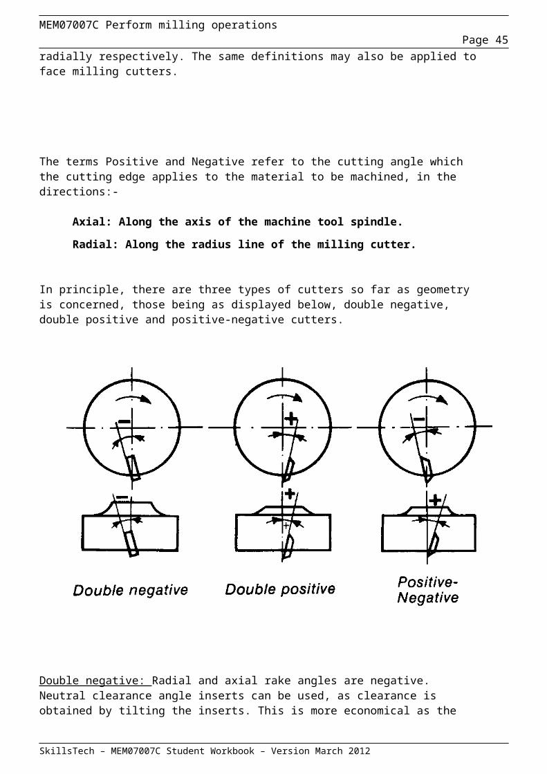
In principle, there are three types of cutters so far as geometry is concerned, those being as displayed below, double negative, double positive and positive-negative cutters.
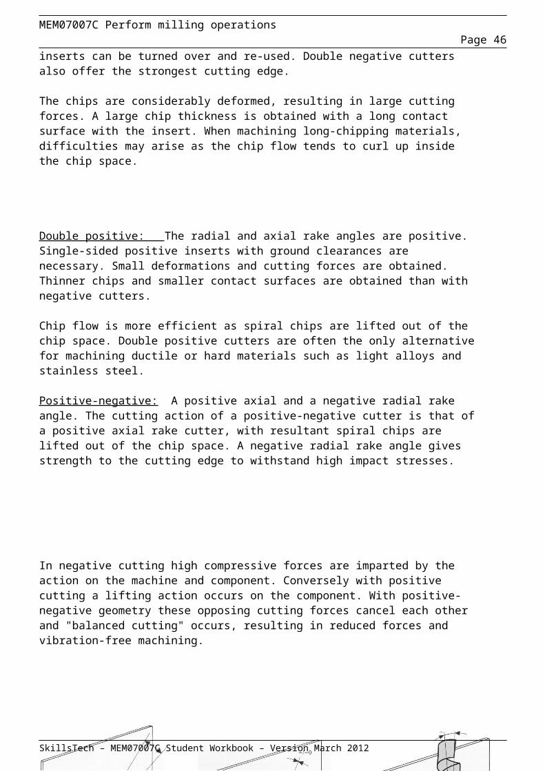
Double negative: Radial and axial rake angles are negative. Neutral clearance angle inserts can be used, as clearance is obtained by tilting the inserts. This is more economical as the inserts can be turned over and re-used. Double negative cutters also offer the strongest cutting edge.
SkillsTech – MEM07007C Student Workbook – Version March 2012
MEM07007C Perform milling operationsPage 35
The chips are considerably deformed, resulting in large cutting forces. A large chip thickness is obtained with a long contact surface with the insert. When machining long-chipping materials, difficulties may arise as the chip flow tends to curl up inside the chip space.
Double positive: The radial and axial rake angles are positive. Single-sided positive inserts with ground clearances are necessary. Small deformations and cutting forces are obtained. Thinner chips and smaller contact surfaces are obtained than with negative cutters.
Chip flow is more efficient as spiral chips are lifted out of the chip space. Double positive cutters are often the only alternative for machining ductile or hard materials such as light alloys and stainless steel.
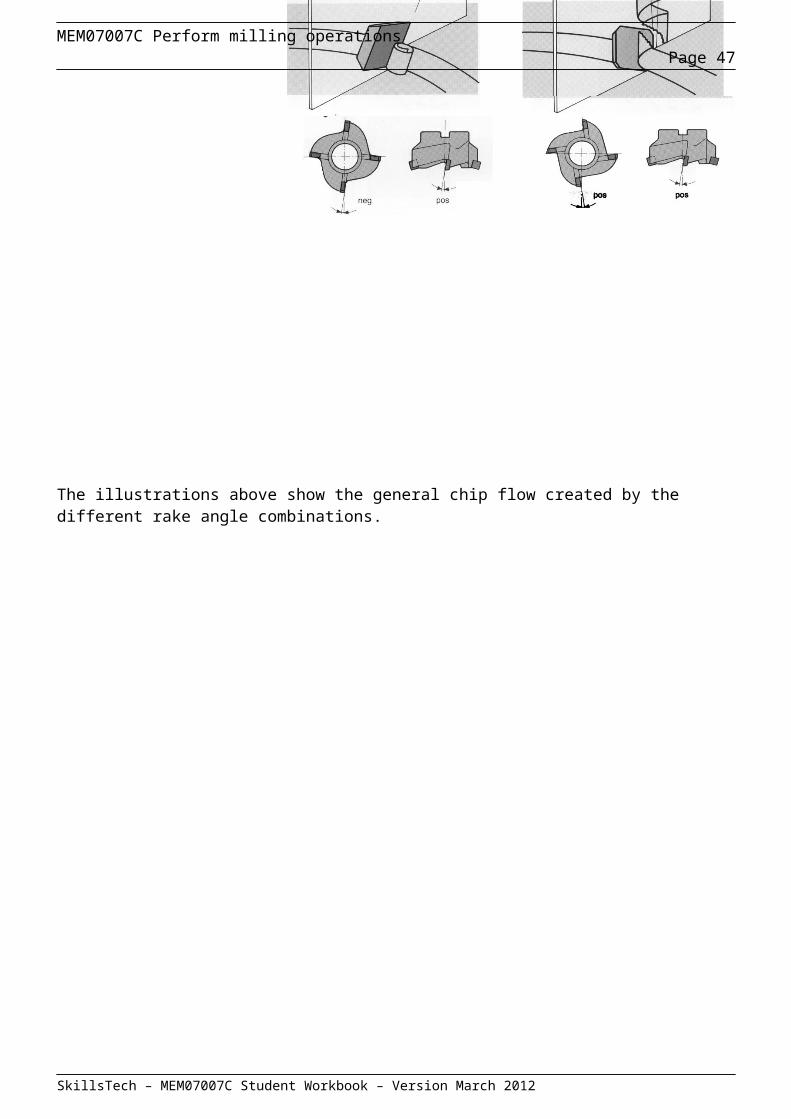
Positive-negative: A positive axial and a negative radial rake angle. The cutting action of a positive-negative cutter is that of a positive axial rake cutter, with resultant spiral chips are lifted out of the chip space. A negative radial rake angle gives strength to the cutting edge to withstand high impact stresses.
In negative cutting high compressive forces are imparted by the action on the machine and component. Conversely with positive cutting a lifting action occurs on the component. With positive-negative geometry these opposing cutting forces cancel each other and "balanced cutting" occurs, resulting in reduced forces and vibration-free machining.
The illustrations above show the general chip flow created by the different rake angle combinations.
SkillsTech – MEM07007C Student Workbook – Version March 2012
MEM07007C Perform milling operationsPage 36
SkillsTech – MEM07007C Student Workbook – Version March 2012

MEM07007C Perform milling operationsPage 37
Cutter types
Milling cutters can be classified according to the type of construction or the function they perform. There is a vast range of cutter types and each type may have a variety of applications.
There are three principle types of construction:
solid cutters inserted tooth cutters brazed on tip cutters
Solid cutters are usually small in size and made from a single piece of steel. The type of steel used depends on the material the cutter is designed to machine.
Inserted tooth cutters have cutting teeth made form a material harder and more durable than that used for the body. Depending on the strength requirements of the cutter, a variety of materials may be selected to manufacture the cutter body. The teeth are normally made of high speed steel or tungsten carbide. This type of construction allows the body to be used indefinitely and the teeth either sharpened or replaced as necessary. This type of construction is normally use for larger cutters.
Brazed on tip cutters have carbide tooth tips brazed onto a solid cutter body.
Cutter Functions
When cutters are classified by function, they fall into two main categories, standard and special. Standard cutters are those frequently used and stocked by a machine tool shop. Special cutters are constructed to perform similar types of work but have a special profile, different number of teeth or the angle of the teeth are of a special profile.
Cutters may be classified by the function they perform, a follows:
plain milling cutters end milling cutters face milling cutters side and face cutters slotting cutters slitting saws angle cutters tee slot cutters woodruff key cutters form or profile cutters fly cutters special milling cutters
SkillsTech – MEM07007C Student Workbook – Version March 2012

MEM07007C Perform milling operationsPage 38
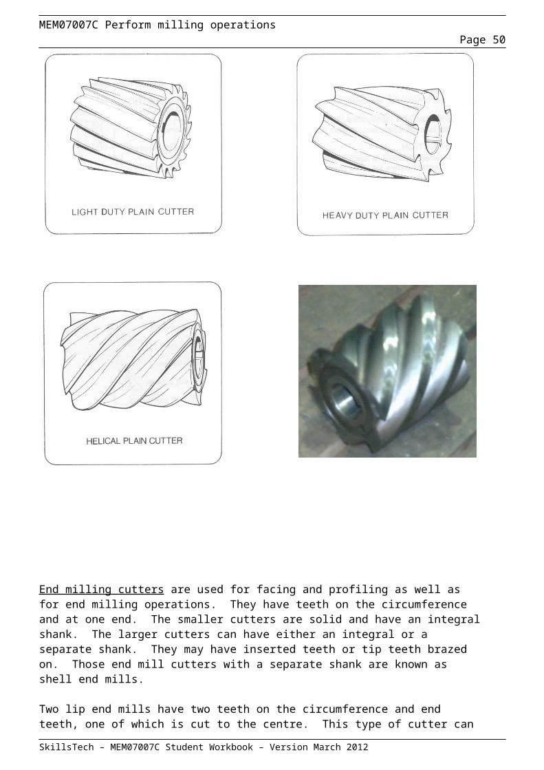
Plain cutters are cylindrical with teeth on the periphery only. They are made in many diameters and widths the wider cutters being used for slab milling.
Plain cutters are the most commonly used and mainly used for fast removal of material to produce a flat surface. Plain cutters have a helix angle of about 25˚ for finishing and 25 to 45˚ for heavy duty roughing. When the helix angle exceeds 45˚ the cutter is called a helical cutter.
Helical cutters are suitable for intermittent cuts in contour and profile milling. They have a very smooth action and produce a good finish. They are efficient for light cuts in softer materials, but less efficient than plain cutters for deep cuts in slab milling.
SkillsTech – MEM07007C Student Workbook – Version March 2012
MEM07007C Perform milling operationsPage 39
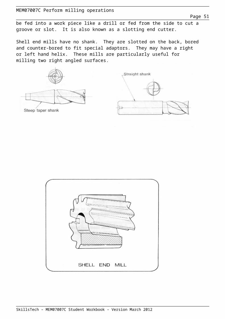
End milling cutters are used for facing and profiling as well as for end milling operations. They have teeth on the circumference and at one end. The smaller cutters are solid and have an integral shank. The larger cutters can have either an integral or a separate shank. They may have inserted teeth or tip teeth brazed on. Those end mill cutters with a separate shank are known as shell end mills.
Two lip end mills have two teeth on the circumference and end teeth, one of which is cut to the centre. This type of cutter can be fed into a work piece like a drill or fed from the side to cut a groove or slot. It is also known as a slotting end cutter.
Shell end mills have no shank. They are slotted on the back, bored and counter-bored to fit special adaptors. They may have a right or left hand helix. These mills are particularly useful for milling two right angled surfaces.
SkillsTech – MEM07007C Student Workbook – Version March 2012

MEM07007C Perform milling operationsPage 40
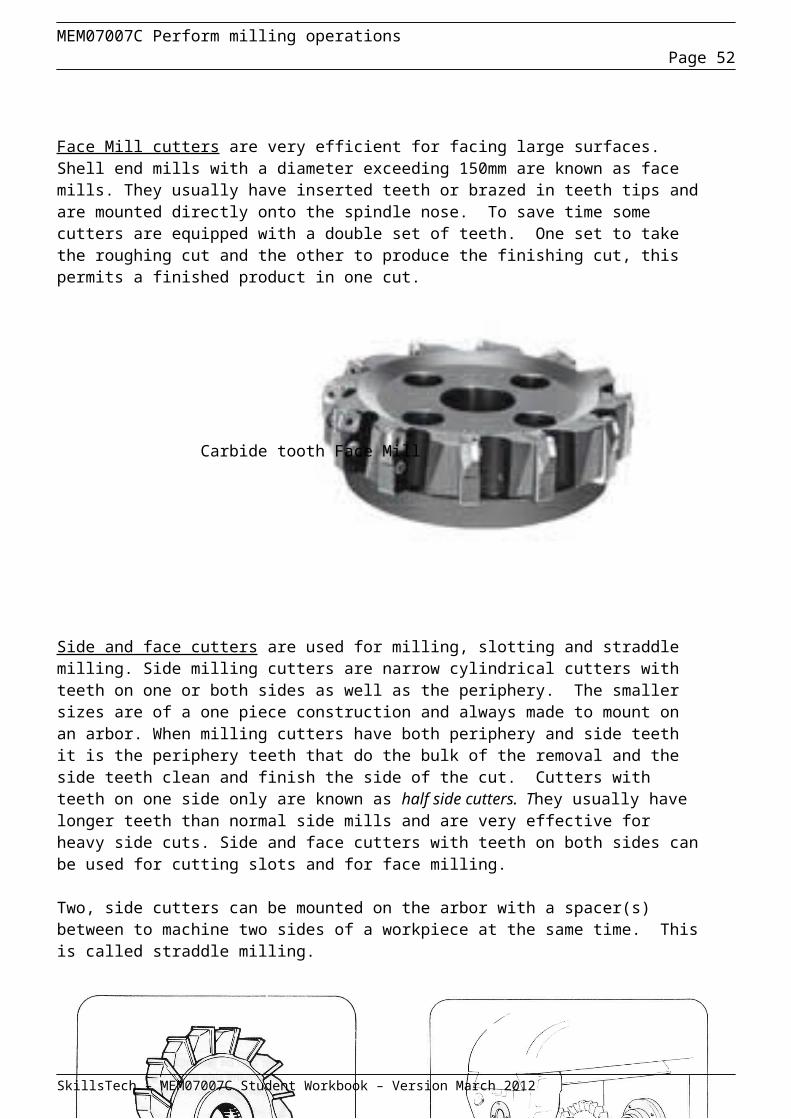
Face Mill cutters are very efficient for facing large surfaces. Shell end mills with a diameter exceeding 150mm are known as face mills. They usually have inserted teeth or brazed in teeth tips and are mounted directly onto the spindle nose. To save time some cutters are equipped with a double set of teeth. One set to take the roughing cut and the other to produce the finishing cut, this permits a finished product in one cut.
Carbide tooth Face Mill
Side and face cutters are used for milling, slotting and straddle milling. Side milling cutters are narrow cylindrical cutters with teeth on one or both sides as well as the periphery. The smaller sizes are of a one piece construction and always made to mount on an arbor. When milling cutters have both periphery and side teeth it is the periphery teeth that do the bulk of the removal and the side teeth clean and finish the side of the cut. Cutters with teeth on one side only are known as half side cutters. They usually have longer teeth than normal side mills and are very effective for heavy side cuts. Side and face cutters with teeth on both sides can be used for cutting slots and for face milling.
Two, side cutters can be mounted on the arbor with a spacer(s) between to machine two sides of a workpiece at the same time. This is called straddle milling.
SkillsTech – MEM07007C Student Workbook – Version March 2012

MEM07007C Perform milling operationsPage 41
Slotting cutters only have teeth on their periphery and are mainly used for cutting slots or keyways.
Special purpose slotting cutters resemble side cutters, but the teeth on the two sides and the periphery are staggered or interlocked. Alternate teeth have opposite helix angles much like a circular saw but with no set. This makes slot cutting smoother and more accurate.
There are two types of slotting cutters, one piece and interlocking. The interlocking slotting cutter consists of two halves with the teeth overlapping where they meet. This enables the width across the side teeth to be adjusted by shims or spacers giving it the ability to cut a range of slot sizes. This feature also gives it the ability to compensate for wear and re-sharpening.
Slitting saws are used for cutting off sections or for cutting deep, narrow slits. The slitting saws used for light cuts have peripheral teeth and relieved sides; that is the teeth are wider than the body.
Smaller size slitting saws can be mounted the same as plain cutters clamped between spacers on an arbour.When mounting thin saws on an arbor do not use a key as this will allow slippage if the blade becomes trapped by the workpiece. Large size slitting saws are mounted on a special flange adaptor which is then fitted on the arbor.
Slotting saws should be operated at proportionately lower speeds per tooth than normal cutter because of their thin profile and their susceptibility to damage.
SkillsTech – MEM07007C Student Workbook – Version March 2012
MEM07007C Perform milling operationsPage 42
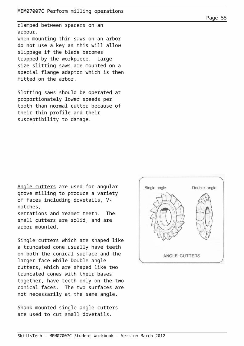
Angle cutters are used for angular grove milling to produce a variety of faces including dovetails, V-notches, serrations and reamer teeth. The small cutters are solid, and are arbor mounted.
Single cutters which are shaped like a truncated cone usually have teeth on both the conical surface and the larger face while Double angle cutters, which are shaped like two truncated cones with their bases together, have teeth only on the two conical faces. The two surfaces are not necessarily at the same angle.
Shank mounted single angle cutters are used to cut small dovetails.
Tee slot cutters are used to cut the wide groove at the bottom of tee slot in machine tables. A narrow grove must be milled first to accommodate the shank of the tee cutter. The cutter consists of a small slotting cutter with an integral shank. Larger size tee slot cutters may be mounted on a separate shank.
Woodruff key cutters are similar in appearance to the tee slot cutter but would normally have narrower teeth. The smaller sizes have straight peripheral teeth but no side teeth. They are made in sizes to cut semi-cylindrical keyways fitting standard Woodruff keys.
SkillsTech – MEM07007C Student Workbook – Version March 2012
MEM07007C Perform milling operationsPage 43
Form (or profile) cutters usually have curved tooth outline and are used to machine contours. They are normally solid but some types may have inserted teeth. There are two basic types of cutters distinguished by tooth profile. They are:
formed profile form relieved
The teeth of formed profile milling cutters are of the same shape as plain cutter teeth but are curved or profiled in outline.
Form relieved cutters have very thick teeth with the back having a slightly smaller diameter than the cutting edge. This is to provide a cutting clearance. The teeth have a constant profile for their entire thickness (front to back). They are shaped by grinding down the face of the teeth to maintain the profile.
Standard form milling cutters are available in a wide range of profiles for cutting radii, rounded grooves, gears, sprockets and splines. There are a variety of special shape/purpose cutters also available.
Form relieved cutters are expensive to produce and to sharpen. It is therefore advisable to operate at cutting speeds less than normal to promote longer life for the cutter. The clearance angle for these cutters is small due to the curved relief, so to prevent the clearance surface rubbing on the work a slower feed rate is recommended.
SkillsTech – MEM07007C Student Workbook – Version March 2012

MEM07007C Perform milling operationsPage 44
Fly cutters have a single point tool similar to that used on a lathe. It is clamped by screws in a special holder having a taper to suit the spindle of the milling machine. The cutter tip can be ground to cut the required shape or profile. As the fly cutter has only a single tip the feed rate must be kept low.
Special milling cutters may be required when a special profile cutter or a cutter having a special tooth arrangement can reduce the time of set up and the number of operations required.
One example of special cutters is a face cutter for aluminium that has only two teeth. As the teeth are inserted individually and have brazed on tungsten carbide tips, the cutter can be operated at a much higher speed, achieving good stock removal.
When using special milling cutters it is possible to control the cutting depth of each tooth to produce a finer finish. One tooth may be set to do the roughing cut and the other set slightly deeper to make the finishing cut.
The tooth angle of these cutters can be set individually to suit different types of materials to be machined.
SkillsTech – MEM07007C Student Workbook – Version March 2012
MEM07007C Perform milling operationsPage 45
Mounting the cutter
Cutters are rotated by the milling machine spindle. They may be provided with an integral spindle mounting shank or require the use of separate mounting parts. To obtain efficient operation and to produce work of a high quality, cutters must be rigidly supported and run true. This can only be achieved if the cutter has been mounted onto the machine correctly.
In general there are two types of milling cutter construction. Those that have an integral shank, either parallel or tapered, eg. end mills, tee slot cutters and those that are mounted onto an arbor eg. face mill, saws etc.
Integral shank cutters are mounted in a collet adaptors, collet chucks or taper adaptors depending on the style of the shank. Arbor mounted cutters have an accurately machined bore and depending on the style of the cutter, they are mounted on a stub arbor or a horizontal arbor.
Below are some examples of mounting different types of cutters.
End Mill with integral taper shank
SkillsTech – MEM07007C Student Workbook – Version March 2012
MEM07007C Perform milling operationsPage 46
Cutting fluids
Cutting fluids play an important part in machining operations. It is important for the machinist or machine operator to have a good understanding of the types of cutting fluids available and their specific application to machining operations.
Functions of cutting fluids
Cutting fluids have four main functions which are to : Reduce friction, Remove heat, Carry away swarf. Prevent corrosion
In metal machining operations, there is a high level of friction between tool and work piece. Because of this friction, tool and work piece wear cannot be avoided.
The cutting fluid forms a film between tool and work piece and reduces wear problems. Similarly, cutting fluid decreases tool and work piece distortion and assists in giving a good surface finish by removing the heat generated. Also, cutting fluid removes the chips from the cutting zone allowing an easy and clean machining operation.
Types of cutting fluids and their application
There are a lot of different types of cutting fluids to meet the requirements of different metal machining operations. In some operations, lubrication is important and in some operations cooling may be more important than the lubrication. In machining operations forming small chips, the detergency is the most important factor. Therefore, in order to meet these kind of requirements, different types of cutting fluids are formulated. In order to meet the requirements of every need, generally four different groups of cutting fluids are manufactured:
Neat oils - non water based Emulsified Oils ( emulsions / soluble oils ) - water based Semi Synthetic Products - water based Synthetic Products - water based
Neat Oils
These kind of products are used in a machining operation in which lubrication is the most important factor. A neat cutting oil is an oil derived from petroleum, animal, marine or vegetable origin, used straight or in combination. The straight un-compounded form is restricted to very light duty application on metals of high machinability, such as aluminium, magnesium, brass and sulphurised or lead free steels. They are satisfactory only as hydrodynamic or fluid-film type lubricants. Mineral oils must be compounded with surface reactive additives if they are to be used as a boundary or extreme pressure lubricant.
SkillsTech – MEM07007C Student Workbook – Version March 2012
MEM07007C Perform milling operationsPage 47
Emulsified Oils ( Emulsions / Soluble Oils )
These fluids are suspension of oil droplets in water. They are made by blending the oil with emulsifying agents and other materials. The addition of animal or vegetable fats, oils or ester products give super fatted emulsions of greater lubricating value. The addition of sulphurised chlorine produces fluids of even greater lubricating value.
Semi Synthetic Products
These fluids are essentially a combination of emulsified oils and synthetic products. These products contain less mineral oil than emulsions. They combine the lubricating properties of emulsions with the cooling properties of synthetic products.
Synthetic Products
These products do not contain any mineral oil. When they are mixed with water they form transparent solutions. They are used in operations in which cooling is more important than lubrication and according to application area, lubricating additives, corrosion inhibitors, and bactericides are included in the formulation.
Replacing an old emulsion with new emulsion
In the situation of replacing an old emulsion with a new emulsion, the system should be cleaned perfectly in order to have maximum performance and maximum effective life from the new emulsion. This may be checked with a refractometer.
Before preparing a new emulsion, physical and biological cleaning of the emulsion tank, pipes and machine parts should be done.
Physical cleaning is simply done by cleaning all of the dirt, swarf and other solid particles from the system. In order to have maximum effective life, the physical cleaning of the emulsion should be done once every 6-12 months by putting the emulsion into a separate container and physically cleaning the emulsion tank and piping. After cleaning the system, the emulsion again is put into the emulsion tank.
The biological cleaning of the system is done by using a disinfectant to eliminate all the microbes and bacteria from the system.
SkillsTech – MEM07007C Student Workbook – Version March 2012
MEM07007C Perform milling operationsPage 48
The effects of machine lubricating oil on the emulsions
All the oils such as hydraulic oils and lubricating oils that contaminate the emulsion are known as tramp oil. The contamination of the emulsion by these oils is a very undesirable situation.
If the concentration of tramp oil exceeds 3%, the following problems will occur;
When the emulsion is un-circulated, tramp oil covers the top of the emulsion, and the bottom of the emulsion is un-aerated and anaerobic bacteria may grow resulting in a bad smell. Tramp oil is also a good nutrient for aerobic bacteria. Therefore aerobic bacteria may also grow resulting in bad odours. Fume and smoke may form at the cutting zone, and:
The stability of emulsion decreases. The lubricity and cooling capacity of the emulsion decreases. Tramp oil forms adhesive deposits around the machine parts and work pieces. When the system is not circulated, tramp oil should be skimmed from the top of the emulsion.
Corrosion problems and how they can be avoided
All the high quality products are formulated to minimise corrosion problems. But, because of the following reasons, emulsions may cause corrosion problems:
Low concentration of emulsion, High salt concentration in the emulsion ( in the case of water with high concentration of salts), Bacterial growth, Use of water with high concentration of chlorine and with high hardness.
Cutting Fluid Safety
You should ensure that coolant reservoirs are kept clean and free from contamination. Bacteria in the coolant/cutting oil can cause infections if allowed to make contact with broken skin such as cuts and scratches etc.
Always wear appropriate PPE when mixing emulsions or performing maintenance operations with a cooling system.
Avoid breathing fumes or vapours from cutting tools or from overheated coolant.
SkillsTech – MEM07007C Student Workbook – Version March 2012

MEM07007C Perform milling operationsPage 49
Cutting Parameters
The spindle RPM necessary to achieve a recommended peripheral speed depends mainly on two factors. The first being the size of the milling cutter, and second being the recommended CS for tool material and job material used.
The “best” speed is determined by the considering a number of other associated factors such as width and depth of cut, surface texture required, type of cutting fluid and method of application, rigidity of the job, rigidity of the setup and power and speed available.
The output of the spindle on a milling machine is the same as a conventional lathe, that is RPM. Therefore the formula for calculating RPM is very similar to that of the lathe formula. The only difference is for milling RPM the diameter of the cutter is required as shown below.
RPM = 300 x CS metres/min Diameter of cutter in mm.
Feed Rate
The rate of feed, or the speed at which the work piece passes the cutter, determines the time required for cutting a job. In selecting the feed there are several factors that should be considered.
Forces are exerted against the work piece, the cutter, and their holding devices during the cutting process. The force exerted varies directly with the amount of feed and depth of cut, and in turn are dependent upon the rigidity and power of the machine. Milling machines are limited by the power they can develop to turn the cutter and the amount of vibration they can resist when using coarse feeds and deep cuts.
The feed and depth of the cut also depend upon the type of milling cutter being used and the type of material the cutting edges are made from.
For example, deep cuts or coarse feeds should not be attempted when using a small diameter end milling cutter. Coarse cutters with strong cutting teeth can be fed at a faster rate because the chips may be washed out more easily by the cutting oil.
Coarse feeds and deep cuts should not be used on a frail work piece if the piece is mounted in such a waythat its holding device is not able to prevent springing or bending.
SkillsTech – MEM07007C Student Workbook – Version March 2012
MEM07007C Perform milling operationsPage 50
Experience and judgment are extremely valuable in selecting the correct milling feeds. Even though suggested rate tables are given. Remember that these are suggestions only. Feeds are governed by many variable factors, such as the degree of finish required, power available and rigidity of set up.
Using a coarse feed, the metal is removed more rapidly but the appearance and accuracy of the surface produced may not reach the standard desired for the finished product. Because of this fact, finer feeds and increased speeds are used for finer, more accurate finishes, while for roughing, use a comparatively low speed and heavy feed. More mistakes are made on over speeding and under feeding than on under speeding and overfeeding.
Over speeding may be detected by the occurrence of a squeaking, scraping sound. If vibration (referred to as chattering) occurs in the milling machine during the cutting process, the speed should be reduced and the feed increased. Too much cutter clearance, a poorly supported work piece, or a badly worn machine gear are common causes of chattering.
Feed Rate Calculations
The feed rate options on a milling machine is usually rated in terms of millimetres per minute, mm/min. Calculations for optimum feed rate on a milling machine take into the RPM of the cutter, the number of teeth or cutting edges on the cutter and also the recommended chip thickness per tooth for the type of cutter. The calculated optimum feed rate should be looked at as a starting point from which variations should be made after other factors such as material condition and work holding has been considered.
The formula for calculating feed rate for a milling machine is:
Feed Rate mm/min = RPM x No Cutting teeth x Chip per tooth
Example: The desired feed per tooth is 0.25 mm, the cutter has 16 teeth, and the rpm setting is 71, then:
Feed rate = 0.25 x 16 x 71
= 284 mm/min
SkillsTech – MEM07007C Student Workbook – Version March 2012
MEM07007C Perform milling operationsPage 51
Set the machine for a feed rate as near as possible to 284 mm per minute, but always lower if the exact feed rate is not available.
The chart below is a sample of feed per tooth data for a number of selected tool types and tool material types cutting Mild Steel. For more information see selected tool manufactures catalogues.
Note: These values are for college machines and are to be used as a guide only. You should refer to
manufacturers data sheets for further information.
SkillsTech – MEM07007C Student Workbook – Version March 2012
Milling cutter Feed per tooth chartHIGH
SPEED
STEEL
Mild Steel (mm)Face Mill 0.1-0.2
Slab Mill 0.05-0.1
End Mill 0.02-0.05
Straight tooth side and face cutter 0.01-0.021Staggered tooth side and face cutter 0.02-0.05Saw 0.01-0.02Form Cutter 0.02-0.05Slot drill 0.05-0.1
CARBIDE
Face Mill 0.1-0.12End Mills 0.1-0.2Slot Drills 0.05 –0.15Carbide Saws 0.08-0.15
MEM07007C Perform milling operationsPage 52
TECHNICAL INFORMATION - END MILLS/SLOT DRILLS Speed selections and application
SkillsTech – MEM07007C Student Workbook – Version March 2012
Steel groupHardness/strength Limits
Material to be machinedTypical within hardness groups nominated
Speed selection – Vc, m/min (metres per minute
Cutter surface coating
Grade of cutter
Regular HSSCoHSS(M35)
HSSCo8(M42)
Micrograin Carbide
Mild steelsUp to 500N/mm2
149 Brinell50.1 kg/mm2
Mild steels Cast irons (soft), low nonalloyed steels, Bronze, Brasses, eg. ASIS-1010, 1030, 1214.
UncoatedTiNite (TiN)TiCNite (TiCN)AlTiNite (TiAlN)
20/2520/3030/40N/A
25/3025/4035/50N/A
30/3535/5040/6040/60
40/60N/A60/15060/150
Medium tensile steels 850 N/mm2
252 Brinell (25Rc)86.7 kg/mm2
Steel forgings, Cast steels, Hard brass/bronze/copper,Cast iron (hard), free machining stainless steel – eg. 304type, eg. AISI-1040, 1045, 1060.
UncoatedTiNite (TiN)TiCNite (TiCN)AlTiNite (TiAlN)
12/1717/2020/25N/A
15/2020/2525/30N/A
20/2525/3530/4530/45
30/50N/A60/8060/80
High tensile steels850/1000 N/mm2
296 Brinell (31Rc)102 kg/mm2
Low alloys, Ferritin high carbon steels, Free machining stainless steels, Tool steels, Austenitic stainless steels (316, 321, etc.), eg. ASIS-P20, 4135, 4140, 52100, 8620.
UncoatedTiNite (TiN)TiCNite (TiCN)AlTiNite (TiAlN)
N/RN/RN/RN/A
12/1717/2520/35N/A
15/2020/3025/4025/40
25/40N/A50/7050/70
High alloy steels1000/1300 N/mm2
383 Brinell (41Rc)132.6 kg/mm2
Heat resistant, high alloy, high strength steels, High strength stainless steels. Eg. AISI Grades Pre-heat treated – H13,D2 , A2, S7, 420S/s, 4340.
UncoatedTiNite (TiN)TiCNite (TiCN)AlTiNite (TiAlN)
N/RN/RN/RN/A
8/1212/2017/25N/A
10/1515/2520/3020/30
20/30N/A40/6040/60
Coated end mills can exceed the above hardness levels.Commercial carbide cutters recommended in excess of the listed hardness rangesAluminiumAlloyed aluminium
Silicon alloysCastings 10%Si max
UncoatedTiNite (TiN)TiCNite (TiCN)AlTiNite (TiAlN)
40/6060/8080/90N/A
50/7070/9090/100N/A
60/8080/120100/120100/120
120/180N/A200/400200/400

MEM07007C Perform milling operationsPage 53
CUTTING CONDITIONS FACTOR – END AND SLOT DRILLS
FEED RATES
Feed rate per tooth: f (mm) . (Chip load)
The nominated values are the rates per tooth to suit regular short series, which are further modified by the conditions given in Table 2.
When using long series cutters, reduce cutter conditions:E.g.: RPM x 0.6 Feed (f) x 0.8
"RMR - Sinusoidal roughing cutter coarse pitch. For fine pitch roughing forms, reduce feed x 0.7
SkillsTech – MEM07007C Student Workbook – Version March 2012
Diameterof cutter
End Mill (f)'RMR (f)(Roughing)
Carbide Endmill<31 Rc >30-50Rc
3 0.004 - 0.015 0.008
4 0:008 - 0:020 0.012
6 0.010 0.017 0.030 0.012
8 0.015 0:020 0:035 0.025
10 0.020 0.031 0.040 - 0.025
12 0.025 0.040 0.045 0.025
14 0.030 0.048 0.050 0.040
16 0:050 0.057 0:055 0.050
18 0.060 0,065 0.060 0.050
20 0:070 0.070 0.070 0.050
22 0:075 0:072 0:075 0.060 -
25 0.080 0.075 0.080 0.070
32 0.090 0.077 - - -
40 0.095 0:080 -
50 0.100 0:085 -

MEM07007C Perform milling operationsPage 54
Table 2 - Cutting Conditions Factor (C)
SkillsTech – MEM07007C Student Workbook – Version March 2012
FEED FACTORS
FINISHING SIDE CUT
PRE MILLING SIDE CUT
ROUGHING SIDE CUT
SOLID ROUGHING SLOTTING
SOLID ROUGHING SLOTTING
END MILLS 1.8 1.0 0.8 1.2 0.8RMR - 1.5 1.2 1.5 1.0
MEM07007C Perform milling operationsPage 55
Review Questions – Determine Job Requirements
Question 1
List two (2) sources that a drawing, or a specification for a machining job, may be obtained.
a) ______________________________________________________________
b) _______________________________________________________________
Question 2
What does a Standard Operating Procedure (SOP) detail?
_____________________________________________________________________
_____________________________________________________________________
Question 3
What is the nominal diameter of a thread designated M20 on a drawing?
________________________________________________________________
Question 4
What are the two methods for designating surface texture of a component designated on a drawing?
___________________________________________________________________________________
___________________________________________________________________________________
___________________________________________________________________________________
SkillsTech – MEM07007C Student Workbook – Version March 2012
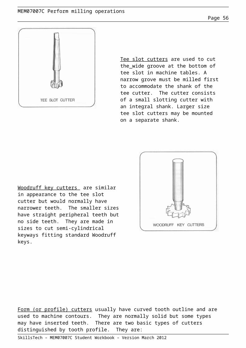
MEM07007C Perform milling operationsPage 56
Question 5
What are the three (3) main causes of a poor surface finish when using Tungsten carbide insert tips?
a)_________________________________________________________________
a) ________________________________________________________________
c) _________________________________________________________________
Question 6
List two (2) types of materials, from which, tool bits are manufactured.
a) ________________________________________________________________
b) ________________________________________________________________
Question 7
Cutting speed, feed and depth of cut influences ‘tool life’. What factors, other than the material of the cutter and job, have an influence on the setting of these parameters?
____________________________________________________________________________________
____________________________________________________________________________________
____________________________________________________________________________________
____________________________________________________________________________________
Question 8
Name the five materials most commonly used for making milling cutters.
____________________________________________________________________________________
____________________________________________________________________________________
____________________________________________________________________________________
SkillsTech – MEM07007C Student Workbook – Version March 2012
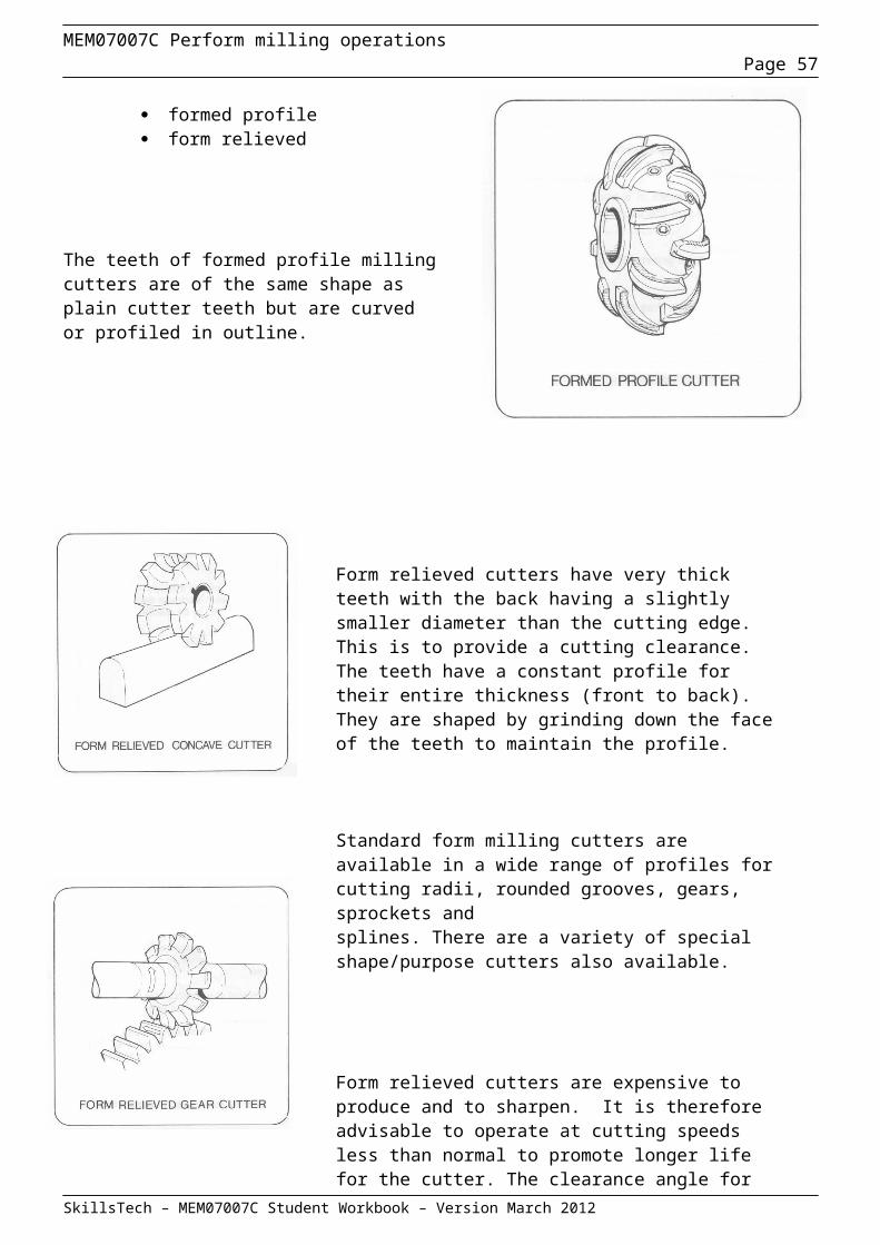
MEM07007C Perform milling operationsPage 57
Question 9
Why are carbon steel cutters operated at lower speeds than tungsten carbide cutters?
________________________________________________________________________
Question 10
Why are carbides and ceramic materials used only as tips?
________________________________________________________________________
Question 11
When milling a workpiece in a vertical mill using an end milling cutter having a right hand cut and a right hand helix, will the cutter tend to be pushed into the taper socket, or pulled out of it?
________________________________________________________________________
Question 12
What advantage does an interlocking cutter have when compared with a one piece slotting cutter?
________________________________________________________________________
________________________________________________________________________
Question 13
What is the difference between formed and form relieved profile milling cutters?
____________________________________________________________________________
____________________________________________________________________________
SkillsTech – MEM07007C Student Workbook – Version March 2012
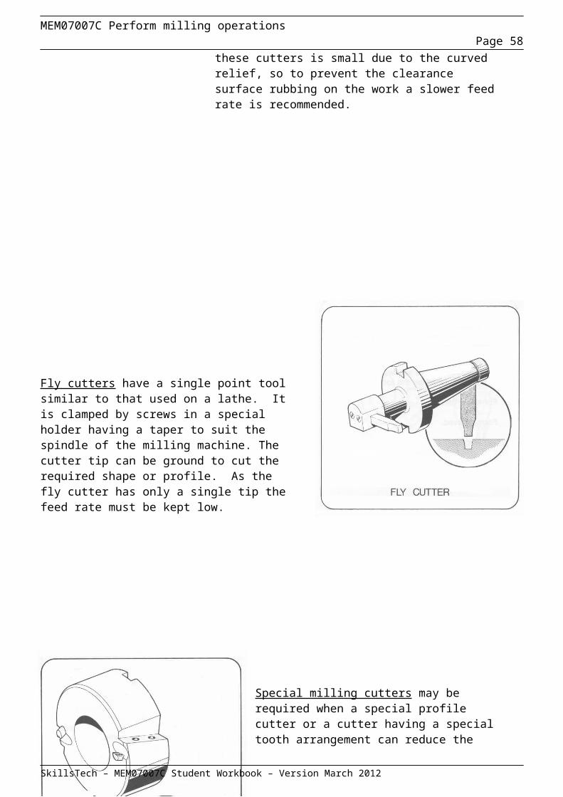
MEM07007C Perform milling operationsPage 58
Question 14
For what milling operation are fly cutters used?
____________________________________________________________________________
Question 15
Why is it important that all cutter mounting parts should be completely cleaned before use?
____________________________________________________________________________
____________________________________________________________________________
Question 16
Why should an arbour mounted cutter be closely supported? What action must be taken before the arbour nut is tightened?
____________________________________________________________________________
____________________________________________________________________________
Question 17
When milling with a slab cutter having a left hand helix, in which direction should the cutter be rotated so that the reaction from a normal cut tends to push the cutter towards the spindle nose?
____________________________________________________________________________
Question 18
Compare the advantages and disadvantages of inserted tooth cutters and cutters with brazed on tips.
____________________________________________________________________________
____________________________________________________________________________
____________________________________________________________________________
SkillsTech – MEM07007C Student Workbook – Version March 2012
MEM07007C Perform milling operationsPage 59
Question 19
Describe three ways of mounting milling cutters.
____________________________________________________________________________
____________________________________________________________________________
____________________________________________________________________________
Question 20
Which will produce the better finish – a helical cutter or a plain cutter?
____________________________________________________________________________
Question 21
Sketch a slotting end cutter and a half side cutter.
Question 22
What is meant by the term milling cutting speed?
____________________________________________________________________________
SkillsTech – MEM07007C Student Workbook – Version March 2012
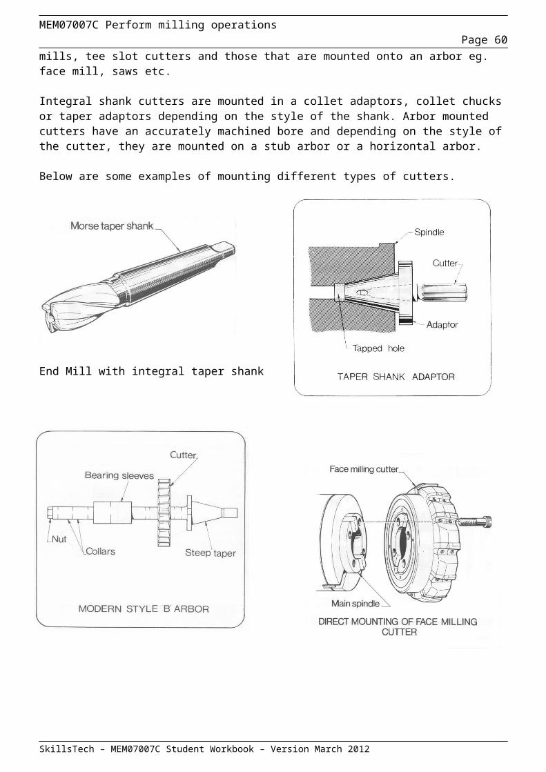
MEM07007C Perform milling operationsPage 60
Question 23
If the required cutting speed is 39 m/min and the cutter has a diameter of 218 mm, calculate the machine rpm setting.
Question 24
A cutter of 36 mm diameter is rotating at 600 rpm. What is its cutting speed?
Question 25
Define the term milling feed rate.
____________________________________________________________________________
____________________________________________________________________________
Question 26
State four factors affecting the choice of feed rate.
________________________________________________________________________
________________________________________________________________________
________________________________________________________________________
________________________________________________________________________
SkillsTech – MEM07007C Student Workbook – Version March 2012
MEM07007C Perform milling operationsPage 61
Question 27
Sketch and fully label a Plain Arbor.
Question 28
Label the following cutter diagrams to identify the axial and radial rake type of each milling cutter.
Radial = ___________ Radial = ___________ Radial = ___________
Axial = ___________ Axial = __________ Axial = ___________
SkillsTech – MEM07007C Student Workbook – Version March 2012
MEM07007C Perform milling operationsPage 62
Question 29
Name the type of cutters shown on the following pages and state a suitable use for each.
SkillsTech – MEM07007C Student Workbook – Version March 2012

MEM07007C Perform milling operationsPage 63
SkillsTech – MEM07007C Student Workbook – Version March 2012
MEM07007C Perform milling operationsPage 64
SkillsTech – MEM07007C Student Workbook – Version March 2012
MEM07007C Perform milling operationsPage 65
Question 30
What are the four main functions of cutting fluids?
_________________________________________ ________________________________________
_________________________________________ ________________________________________
Question 31
What type of a cutting fluid should be used when lubrication is the most important characteristic required?
____________________________________________________________________________________
Question 32
What type of a cutting fluid should be used when cooling is more important than lubrication?
____________________________________________________________________________________
Question 33
What processes must be completed before a new cutting fluid is added to a machine?
____________________________________________________________________________________
Question 34
List 2 problems that can occur when tramp oil exceeds 3%
____________________________________________________________________________________
____________________________________________________________________________________
Question 35
List 2 personal safety practises that should be followed when using cutting fluids.
____________________________________________________________________________________
____________________________________________________________________________________
SkillsTech – MEM07007C Student Workbook – Version March 2012
MEM07007C Perform milling operationsPage 66
Section 5 – Perform milling operations
Setting up work holding devices
Introduction: Work holding and clamping
In preparation to carrying out any milling operation it is essential to know how a workpiece and cutting tool are correctly set up.
This manual describes some of the common methods of work holding, and setting up procedures for workpieces and cutters.
Safety precautions for specific operations are detailed in the text along with the description of the operation.
All safety precautions must be observed when working on the milling machine. Follow all safety instructions detailed in the workshop and make safe working practices a habit.
Work holding and clamping
If work of good quality is to be produced using a milling machine the workpiece must be held firmly in the correct position.
A wide range of accessories is available for this purpose. These accessories must be handled carefully, kept clean, set accurately and used only for their intended purpose.
Rough handling and careless setting of the accessories are dangerous practices in milling machine work. Movement of the workpiece during the milling operation could cause personal injury and damage to the milling machine or the workpiece.
SkillsTech – MEM07007C Student Workbook – Version March 2012
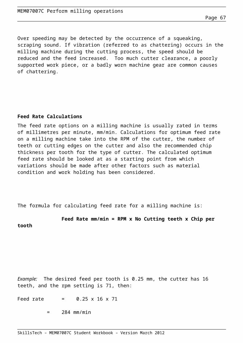
MEM07007C Perform milling operationsPage 67
The work table
The surface of a milling machine work table is accurately machined, smooth and flat. It is square to the column and parallel to the arbor of a horizontal miller or square to the spindle of a vertical miller. The under surfaces of vices, angle plates and other accessories used on the work table are accurately finished.
Any damage to these surfaces will make it difficult to mount the workpiece accurately.
Dirt or metal chips between the table and the workpiece holding device will have the same effect.
Three basic rules must be observed at all times:
treat the table surface with care keep the table and accessories clean. do not use the work table as a storage shelf.
When fitting a vice or other accessory to the work table set it down gently and squarely.
Heavy or cumbersome workpieces should be set on the table using protective strips of wood or soft metal. These protective spacers can then be removed to lower the workpiece gently onto the table.
Whenever possible a lifting device should be used with heavy accessories or workpieces
Use a tray or board placed on the table for cutters and spacing collars when setting up the machine. The sharp teeth of a large and heavy cutter may damage the table surface even when put down gently.
Never assume that a machine is clean. Always clean up before and after machining operations. Brush out the table tee slots and check the edges of any accessories for burrs.
SkillsTech – MEM07007C Student Workbook – Version March 2012

MEM07007C Perform milling operationsPage 68
Types of Vice
To facilitate the mounting of workpieces and to extend the applications of a given milling machine a variety of accessories and attachments are available.
Vices
The milling machine vice is basically a two jaw clamp with one fixed jaw and one movable. It is provided with a base that may be secured to the work table using tee bolts.
There are several types of vices: plain, flanged, swivel, universal and shaft.
Plain vice
The plain vice consists of a fixed and movable jaw with a screw mechanism for adjustment. It is usually made of cast iron and fitted with jaw pads of ground hardened steel. Holes or grooves are provided to permit clamping to the work table using tee bolts.
Flanged vice
The flanged vice is similar to the plain vice, but is larger and stronger. Its body is formed with extra slots in the flange to distribute the load over a greater area of the base. The flanged vice is used to hold large work pieces or when heavy milling cuts are made.
SkillsTech – MEM07007C Student Workbook – Version March 2012
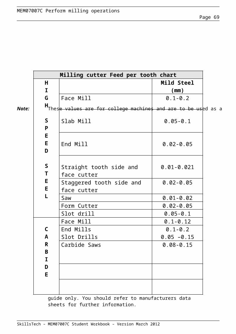
MEM07007C Perform milling operationsPage 69
Swivel vice
The swivel vice is similar to the flanged vice but is mounted on a swivel base with a graduated scale. The vice can be swung through any angle on the horizontal plane.
Universal vice
There are several types of universal vices. Each type has a swivel base and the vice may also be tilted with respect to the base.
Some universal vices are arranged to tilt in two planes and are provided with a swivel arrangement for the jaws. This allows the jaws to be set at any compound angle with respect to the base.
The universal vice is most suited to the tool maker’s trade.
Shaft vice
The shaft vice is self centring and consists of a body with two right angled mounting flanges, two pivots, two movable jaws and a screw mechanism.
The jaws are machined like vee blocks and the screw mechanism opens and closes the jaws. The vee block jaws; centre and support cylindrical workpieces.
SkillsTech – MEM07007C Student Workbook – Version March 2012
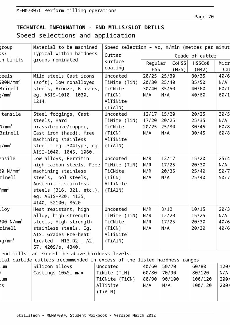
MEM07007C Perform milling operationsPage 70
Setting a Universal milling machine table
When machining a job, that requires parallel features, on a Universal mill it is very important to check that the table is accurately set parallel to the column of the machine. This is necessary because the table may have been rotated on it’s swivel base for a previous job.
A dial indicator is used to ensure that the table travel is parallel to the column by placing the dial plunger on the column face as shown in the diagram. The table is then traversed and adjusted if necessary.
Placing the dial plunger on the machine table and traversing the table would show no movement on the dial irrespective of the angle that the table is currently set to.
After the table travel has been checked for parallel travel the appropriate work holding device may be fitted to the table and aligned if necessary. Instructions for alignment of work holding devices follow.
Setting a plain vice parallel to feed
A machine vice is usually provided with two keyways in its bottom surface. One parallel with the jaws and the other at right angles to the jaws.
To set the vice with its jaws parallel with either the longitudinal or cross feed movement set keys in the appropriate keyway, and place the vice on the work table with the keys engaging a tee slot.
For greater accuracy the keys should be tightened against the same edge of the tee slot. Fit and tighten tee bolts to secure the vice in position. This procedure is sufficiently accurate for most work.
The vice can be set up more reliably and the accuracy of the keyways checked by: using a dial indicator using a try square using a parallel strip using a dial indicator and parallel. SkillsTech – MEM07007C Student Workbook – Version March 2012
Table
Column
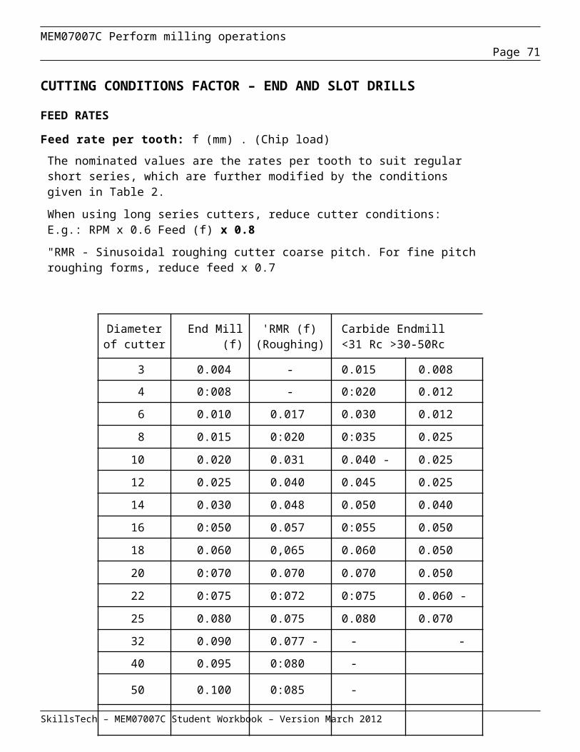
MEM07007C Perform milling operationsPage 71
Using a dial indicator
This procedure is used when the vice jaws are to be aligned with the feed:
mount the vice on the work table with or without keys
finger tighten the tee bolts
set up a dial indicator either with a magnetic base on the front of the column or with a clamp on the arbour
set the dial indicator plunger square against the fixed jaw of the vice
manually operate the feed with which the vice jaws are to be set parallel
note the dial indicator reading at each end of the jaw
traverse the feed back and forth and tap the vice body with a soft headed hammer until the dial indicator reading is the same at each end of the fixed jaw
always tap away from the dial indicator or to avoid damage to the indicator move the plunger away from the jaw before tapping
tighten the tee bolts and re-check the setting with the dial indicator.
Check the vertical alignment of the jaw face with the same dial indicator setting by operating the vertical feed. If the jaw is not vertical replace it or select another vice.
Repeat the checking procedure.
SkillsTech – MEM07007C Student Workbook – Version March 2012
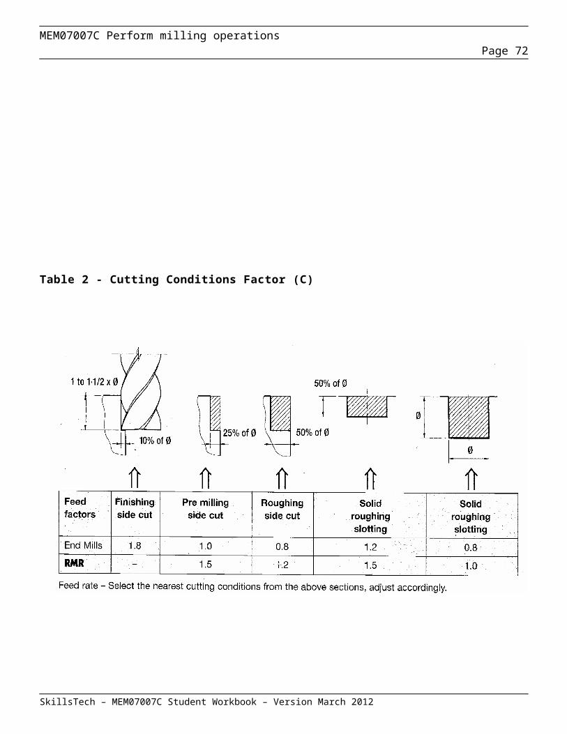
MEM07007C Perform milling operationsPage 72
Using a try square
When vice jaws are to be set parallel with the cross feed, and thus parallel with the arbor use the following procedure:
mount vice on the work table with or without keys
finger tighten the tee bolts
set the stock of a try square firmly against the front face of the knee slide on the column
set the blade of the try square gently against the fixed jaw of the vice
tap the vice frame with a soft headed hammer to align the fixed jaw with the try square
tap away from the try square
tighten the tee bolts and test by lightly clamping two strips of tissue paper between the square blade and the fixed jaw.
When the two strips of paper are held with equal firmness the setting is complete.
SkillsTech – MEM07007C Student Workbook – Version March 2012
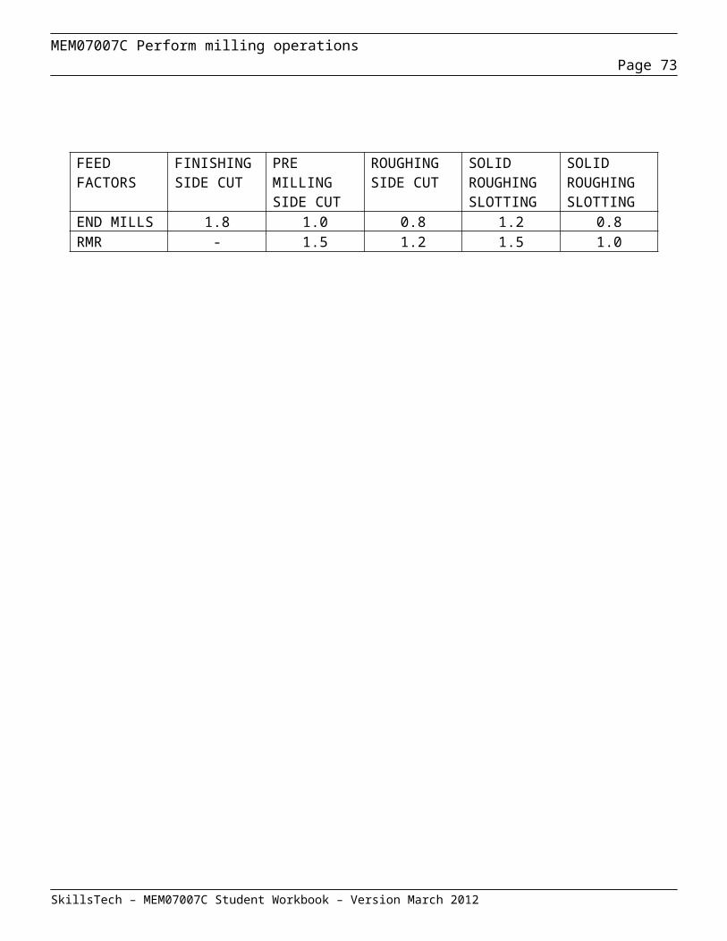
MEM07007C Perform milling operationsPage 73
Using a parallel strip
When vice jaws are to be set parallel with the longitudinal feed and at right angles to the arbor use the following procedure:
mount the vice on the work table with or without keys
finger tighten the tee bolts clamp a parallel strip in the jaws of the vice. The
strip should be long enough to extend beyond both ends of the jaws
traverse the work table towards the column with the manual cross feed until another parallel strip just fits between the clamped parallel strip and the face of the column
check this strip for fit at the other end of the clamped strip
if necessary turn the vice by tapping it with a soft faced hammer
continue traversing and adjusting until the test strip fits exactly at each end of the clamped.
Setting a plain vice at an angle
To set the vice at an angle use the following procedure:
remove the vice mounting keys and set the vice on the work table at approximately the required angle
fit one tee bolt and lightly tighten it set a vernier protractor the precise angle required set the vice to the angle set on the protractor clamp the vice in this position and check angular
setting.
Usually only one of the bolt holes in the vice aligns with a tee slot in the work table in this situation. Use another arrangement to clamp the other side of the vice.
SkillsTech – MEM07007C Student Workbook – Version March 2012

MEM07007C Perform milling operationsPage 74
Setting a swivel vice at an angle
A swivel vice may be set at an angle by:
setting with keys and the vice scale setting with a dial indicator and the vice scale setting with a vernier protractor.
The accuracy obtainable with each setting method varies.
With keys and the vice scale
This is the simplest but least accurate method.
The swivel vice is mounted on the work table and located with keys fitted between the vice base and the table.
The swivelling section of the vice is set to the required angle using the scale provided on the vice.
With dial indicator and the vice scale
This is a more accurate method than using the vice scale alone.
The procedure is as follows:
lock the vice swivel at either 0º or 90º mount the vice on the machine table and use a dial
indicator to align the jaw of the vice with the column set the swivelling section of the vice to obtain the
required angle on the vice scale clamp the swivelling section firmly to the vice
turntable.
SkillsTech – MEM07007C Student Workbook – Version March 2012

MEM07007C Perform milling operationsPage 75
With a vernier protractor
If great accuracy is necessary use the following procedure:
using locating keys mount the swivel vice on the work table
set the swivel section of the vice to obtain the desired angle on the vice scale
set a vernier protractor precisely to the required angle
press the stock of the protractor firmly against the knee slide on the front of the machine column
adjust the swivelling section of the vice until it aligns with the protractor
clamp the swivelling section firmly to the vice turntable
test this setting with two pieces of tissue paper.
Setting a universal vice at an angle
A universal vice can be tilted as well as swivelled.
The swivel angle
To set the swivel angle of a universal vice mount it on the work table and set the swivel angle by following one of the procedures given for the swivel vice.
The tilt angle across the jaws
The tilt angle across the jaws is set using a vernier protractor. The procedure is as follows:
set a parallel strip higher than the vice jaws accurately in the bottom of the vice
clamp the parallel strip in the vice set a vernier protractor precisely to the required
angle press the stock of the protractor firmly against the
work table so that the protractor blade rests lightly against the top face of the parallel strip
adjust the tilt angle of the vice until no light is visible between the blade and the strip
tighten the retaining bolts
SkillsTech – MEM07007C Student Workbook – Version March 2012

MEM07007C Perform milling operationsPage 76
Setting two vices in line
It is sometimes necessary to use two vices to set up a workpiece such as when machining a long slot in a narrow workpiece.
To prevent distortion of the workpiece the two vices must be accurately aligned.
The two vices should be identical or have their fixed jaws located at the same distance from the tee bolt holes in the vice frames.
The setting procedure is as follows:
using keys and tee bolts, mount the vices on the table.
This is sufficiently accurate for most purposes. If greater accuracy is required the following additional procedure should be followed:
slacken the tee bolts on each vice
select a parallel strip long enough to project beyond the ends of both vices
clamp one end of the strip firmly in one of the vices
check that there is sufficient distance between the vices to ensure that the jaws do not obstruct any machining operations
close the jaws of the second vice firmly against the parallel strip
measure the distance from the front of the column to each end of the parallel strip
this distance may be compared using an inside micrometer, a dial indicator or a parallel strip
if necessary move the vices gently until both distances are equal
tighten the tee bolts on each vice and recheck the previous measurements.
SkillsTech – MEM07007C Student Workbook – Version March 2012

MEM07007C Perform milling operationsPage 77
Setting up angles plates: Using a dial indicator
Set the angle plate in approximately the required position.
Insert tee bolts and tighten them finger tight.
Set a dial indicator on the column slide or the arbor of the machine and bring it into contact with the face of the angle plate.
Turn the manual longitudinal feed hand wheel and note any difference in the reading of the dial indicator at each end of the angle plate.
Adjust the position of the plate by gently tapping a lower corner away from the dial indicator with a soft faced hammer until the dial indicator readings are the same at both ends.
Tighten the tee bolts and recheck the face of the plate with the dial indicator.
Using a parallel strip
Set the angle plate on the table.
Insert tee bolts and tighten them finger tight.
Fit a precision parallel or an inside micrometer between the column slide and one end of the angle plate face
Check the fit of the parallel strip between the column face and the other end of the angle plate face.
Adjust the position of the angle plate by gently tapping a lower corner with a soft faced hammer.
Manually operate the cross feed until the parallel strip fits accurately between the column slide and each end of the angle plate.
Tighten the tee bolts and again check the position of the angle plate.
SkillsTech – MEM07007C Student Workbook – Version March 2012

MEM07007C Perform milling operationsPage 78
Angle Plate Face square to the longitudinal feed
Follow the procedure set out on page 67 for setting an angle plate with a dial but use the manual cross feed to move the angle plate along the dial indicator instead of the manual longitudinal feed.
Angle Plate Face at an angle
Set the angle plate on the table.
Insert tee bolts and tighten them finger tight
Set a vernier protractor accurately to the required angle.
Hold the protractor horizontal and press its stock firmly against the column slide
Move the protractor blade gently against the angle plate face.
Adjust the position of the angle plate with a soft-faced mallet by gently tapping a lower corner away from the protractor.
Place a strip of tissue paper between the protractor blade and the angle plate face at each end of the face.
The angle plate is in the correct position when both strips are held equally firmly.
Tighten the tee bolts and again check the alignment.
SkillsTech – MEM07007C Student Workbook – Version March 2012

MEM07007C Perform milling operationsPage 79
Face perpendicular to the table
Set the angle plate face in relation to the column slide.
Set a dial indicator on the column slide or arbor with its contact point bearing against the face of the angle plate.
Operate the manual vertical feed and compare the dial indicator readings at the top and bottom of the face.
If the face is not perpendicular to the table pack with brass shims.
Tighten the tee bolts and check that the angle plate is perpendicular to the table.
Setting up a rotary table
Lift the attachment very carefully, clean the base and place it gently on the table.
If it is large obtain help or use a lifting device.
Protect the table surface with wooden or soft metal strips.
After setting the attachment down remove the protective strips.
If the automatic drive from the longitudinal feed mechanism is used fit the drive gears and connect the drive shaft to the attachment before bolting it down.
Check that the rotary table of the attachment is level as follows:
set up a dial indicator on the column slide or the arbor with its point bearing against the top surface of the table
operate the manual longitudinal feed to move the gauge point from the edge to the centre of the table
operate the manual cross feed to move the point out to the edge again
lift the dial point across any grooves in the table to prevent it being damaged
if the dial reading changes in one direction or both the rotary milling attachment is defective
SkillsTech – MEM07007C Student Workbook – Version March 2012
MEM07007C Perform milling operationsPage 80
Fixtures
Fixtures are special purpose devices for holding workpieces. Their main advantage is that they save time by eliminating the need to mark out.
They are used only where the time and expense involved in making the fixture are outweighed by the time and cost saved in setting up a number of identical items.
They are also valuable when machining even a single item that is difficult or impossible to hold by other work holding methods.
Principles of fixture design
The fixture must hold the workpiece firmly in correct alignment.
The workpiece is located in the fixture by being pressed firmly against a number of reference pegs or machined corners provided for this purpose. If possible the workpiece should be provided with a previously machined face to bear against the fixture reference surfaces.
The use of reference pegs rather than a machined reference surface reduces the likelihood of dirt or surface irregularities upsetting the alignment.
The fixture must hold the workpiece just firmly enough to withstand machining forces without damaging the workpiece.
Large and strong clamps must be used to secure the workpiece in the fixture.
Workpieces which could be damaged or distorted by high point pressures are secured with a relatively large number of small clamps.
If possible a fixture should be so designed that most of the machining forces are taken up by fixed lugs rather than by clamps.
Since the purpose of the fixture is to save time it must be designed to allow the workpiece to be inserted and clamped down quickly. The clamps must be quick-acting and as few in number as possible.
SkillsTech – MEM07007C Student Workbook – Version March 2012

MEM07007C Perform milling operationsPage 81
Fixtures for mass production generally have hydraulically or pneumatically operated power clamps so that all clamps can be opened or closed at the same time by a single control.
Such fixtures are sometimes also provided with arrangements for automatic loading and unloading of workpieces.
Fixture locating elements
The locating elements in fixtures must make firm contact with the workpiece, and the contact area should be as small as possible.
Accordingly they are usually in the form of pegs pressed or screwed into the fixture.
Stops are provided at the end of the fixture to support the workpiece against the force of the cut.
The pegs or stops may be made adjustable to accommodate the rough surface of an unmachined casting. Whenever possible this practice should be avoided by prior machining or other means as it lengthens the time required to set up the workpiece in the fixture.
The pegs or stops must be arranged so that they hold the workpiece in exactly the right position on the fixture, and at exactly the right angle.
SkillsTech – MEM07007C Student Workbook – Version March 2012

MEM07007C Perform milling operationsPage 82
Fixture clamping elementsThe clamping elements used must provide steady, strong pressure and must not obstruct the cutting tool or other machine parts. They should be quick acting.
In some applications it is important that the clamping force be applied in a straight line without a twisting action.
Plain clampThe plain clamp is the one most frequently used. It has a cut-out tail for quick removal, and a spring to lift it when the nut is unscrewed. As with most clamps the nose is rounded to concentrate claming pressure.
Double acting clampThe double acting clamp pivots so that it presses the workpiece downwards and sideways at the same time. It is usually fitted with a handwheel, and is therefore quicker but weaker than the plain clamp.
Cam operating clampThe cam operated clamp is the quickest of all manual clamps. Its limitations are its light clamping force, and its fulcrum screw which must be readjusted should the height of the workpieces vary greatly.
Equalising clampThe equalising clamp is particularly useful for thin workpieces. It is designed to press at two separate points with equal force. This reduces the possibility of workpiece distortion.
Finger clampThe finger clamp provides a straight and twist free clamping force. It is not very strong, and is used mainly for clamping small workpieces.
Gauging surfacesGauging surfaces are sometimes provided on a fixture to serve as reference points for setting the cutters in correct relation with the fixture and the workpiece.
SkillsTech – MEM07007C Student Workbook – Version March 2012
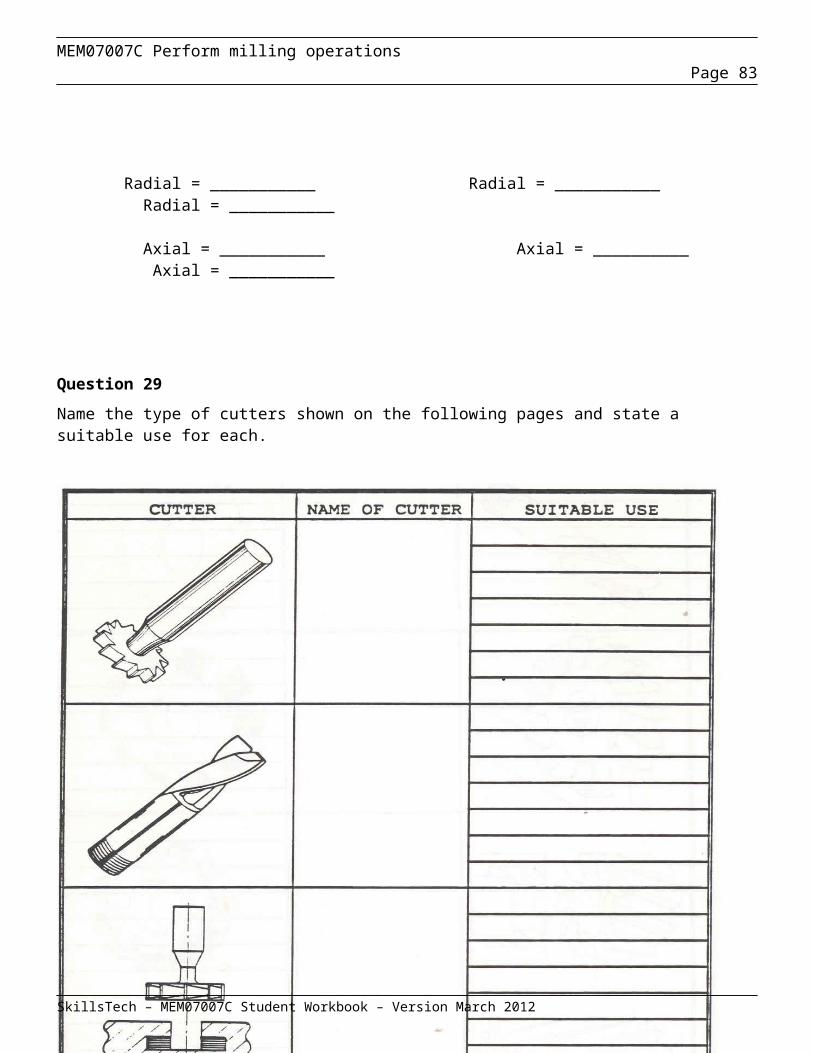
MEM07007C Perform milling operationsPage 83
Review Questions – Setting up workholding devices
Question 1
Why must great care be taken when placing tools or cutters on a milling machine work table?
____________________________________________________________________________________
Question 2
Why is it important that the table and mounting accessories be kept clean?
___________________________________________________________________________________
Question 3
Briefly describe the simplest way of setting a vice parallel to the longitudinal feed.
___________________________________________________________________________________
Question 4
Briefly describe an accurate way of setting a vice parallel to the longitudinal feed.
___________________________________________________________________________________
Question 5
Describe the method of checking that the table of a rotary milling attachment is level.
_____________________________________________________________________________________
SkillsTech – MEM07007C Student Workbook – Version March 2012

MEM07007C Perform milling operationsPage 84
_____________________________________________________________________________________
_____________________________________________________________________________________
Question 6
The pegs and stops used in fixtures have two functions. What are they?
_____________________________________________________________________________________
_____________________________________________________________________________________
Question 7
Describe five principles that need to be considered when designing a fixture
1 ___________________________________________________________________________________
_____________________________________________________________________________________
____________________________________________________________________________
2 ___________________________________________________________________________________
_____________________________________________________________________________________
____________________________________________________________________________
3 ___________________________________________________________________________________
_____________________________________________________________________________________
____________________________________________________________________________
4 ___________________________________________________________________________________
_____________________________________________________________________________________
____________________________________________________________________________
5 ___________________________________________________________________________________
SkillsTech – MEM07007C Student Workbook – Version March 2012

MEM07007C Perform milling operationsPage 85
_____________________________________________________________________________________
____________________________________________________________________________
SkillsTech – MEM07007C Student Workbook – Version March 2012

MEM07007C Perform milling operationsPage 86
Setting up a workpiece
Introduction
The milling machine is often used to produce accurate work. To achieve this accuracy the operator must have a thorough knowledge of the machine and its capabilities. They must operate it carefully and economically. At all times they must be aware of possible hazards, and he must know the safety precautions necessary to prevent them.
When setting up the machine to perform a milling operation, the time involved, and the resulting cost must be weighed against the degree of accuracy required in the finished work. There are almost as many different setting up procedures as there are types of workpieces.
The procedures described in this section are examples of possible approaches to setting up workpieces. Practical and economic factors have been given due consideration in the drawing up of these procedures.
Clamping directly to machine table
Setting up the work directly on the machine table eliminates alignment errors that may otherwise be introduced by a work holding device. Also the time taken to set up the work holding device is saved.
Setting up on the machine table is not only preferable but often necessary as in the case of large workpieces or workpieces of complicated shape which cannot be set in standard work holding devices.
Shafts, particularly when long are best set up in one of the table tee slots. The tee slot will locate and support the shaft over its entire length.
The elimination of work holders also renders the workpiece more capable of withstanding the forces of a heavy cut.
It is difficult to set up small workpieces on the table when the entire top surface of the workpiece is to be machined. In such cases a vice offers a more suitable
SkillsTech – MEM07007C Student Workbook – Version March 2012
MEM07007C Perform milling operationsPage 87
mounting arrangement. A vice also saves time when a small workpiece is to be machined on more than one side.
Using clamps and stops
The various clamps and stops used to set up workpieces on the work table have two functions:
they hold the workpiece down they restrain the workpiece from skewing.
For a light cut stops will not usually be necessary because the grip of the clamp will be adequate to prevent any sliding movement of the workpiece.
When several identical workpieces are to be machine one after another stops can be set on the work table to form a simple fixture and thereby save setting-up time.
Angle plates, packing blocks, step blocks, jacks and braces are also used when setting up on the work table. These devices are selected according to the shape and size of the workpiece.
IMPORTANT Always support the area where the clamping pressure is applied to minimise distortion.
SkillsTech – MEM07007C Student Workbook – Version March 2012
MEM07007C Perform milling operationsPage 88
Setting up a workpiece in a vice
The vice must first be accurately aligned as described in the previous section. The workpiece is then aligned with the previously aligned fixed jaw and the bottom of the vice.
Straight sided workpiece
When a workpiece is already machined accurately overall it is only necessary to seat it properly in the vice to ensure alignment.
Due to unavoidable slack in the slide of the moving jaw this jaw tends to urge the workpiece away from the bottom of the vice when the clamping screw is tightened.
To keep the workpiece seated tap it down with a soft headed mallet while gently tightening the clamping screw. If possible two strips of paper, separated as far as possible, under the workpiece should both be gripped by the workpiece to indicate the workpiece is seated correctly.
When the height of the workpiece is less than the height of the vice jaws it may be necessary to raise the workpiece to perform certain operations such as when the entire top surface is to be machined.
This is achieved by mounting the workpiece on two precision parallel strips. Use a soft headed mallet to keep the workpiece seated while tightening the vice jaws. The workpiece is seated accurately when both parallel strips are firm.
Check that the workpiece is seated correctly after the jaws are fully tightened.
SkillsTech – MEM07007C Student Workbook – Version March 2012
MEM07007C Perform milling operationsPage 89
When a workpiece is already machined on one side only the method of setting up depends on the type of operation to be performed on the workpiece.
To machine one side parallel with the first; seat the machined side against the bottom of the vice as discussed previously.
To machine one side square with the first:
set the machined side against the fixed jaw clamp a circular section bar (copper wire is often
used) in a horizontal position between the workpiece and the moving jaw
Use a soft headed mallet to keep the workpiece seated correctly on parallel strips or paper
there is now line contact only between the workpiece and the moving jaw, and the workpiece is aligned in the vertical plane with the fixed jaw.
When two sides of the workpiece are already machined square the ends can be machined square with the sides:
seat the workpiece with one machine side against the bottom of the vice, and the other side against the fixed jaw
clamp a short vertical cylindrical bar between the workpiece and the moving jaw
the line contact provided by the bar ensures that the workpiece is horizontally aligned with the fixed jaw.
Irregular workpiece
Irregular workpieces having at least one flat side may be clamped in a vice either directly or with the aid of vee blocks, packing blocks, or other suitable clamping accessories.
Irregular workpieces are usually clamped between specially shaped blocks or in fixtures. The vice is then used to hold the fixture in the correct position and to supply clamping pressure.
The workpiece with its clamping accessories is aligned as a unit with the bottom and fixed jaw of the vice as described for straight sided workpieces.
SkillsTech – MEM07007C Student Workbook – Version March 2012
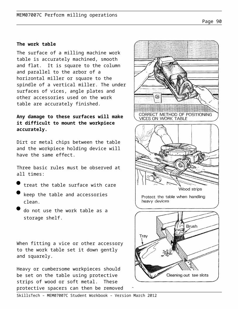
MEM07007C Perform milling operationsPage 90
Setting cutters
To a datum
A datum is an accurately established reference point provided on a workpiece. It may take the form of a plug or dowel which has been fitted into an accurate hole. It can also be a machined surface or corner on the workpiece.
A Datum is used to position the milling machine cutters. The cut is then set with the scales on the manual feeds or with other precision measuring arrangements.
Datum Setting Examples
To move a cutter in a vertical milling machine to a required position, use the following procedure:(NOTE: In the illustration below, the work piece is shown without any clamps to give a clear view of the operation.)
Mount the work piece on the work table using the appropriate accessories.
Fit an aligning bar or cutter to the machine spindle
Operate the manual feeds to lightly trap a feeler gauge of known size between the aligning bar or cutter and the datum
Lock the cross slide and set its graduated dial to read the sum of the thickness of the feeler gauge and the radius of the aligning bar / cutter.
Use the graduated dial to move the aligning bar or cutter to the desired position.
To move a cutter to the centre line of a work piece (flat or round)(Note: For round work pieces, the cutter must be able to reach the centre line of job. An alternative method follows)
Measure the width of the work piece.
Set the cutter to gently hold a feeler gauge of known size against one side of the work piece.
The graduated dial is set to zero, and the manual vertical slide operated to take the work piece clear of the cutter.
The manual cross slide is then operated to set the graduated dial to half the measured width of the work piece, plus half the diameter or width of the cutter, plus the thickness of the feeler gauge used.
SkillsTech – MEM07007C Student Workbook – Version March 2012

MEM07007C Perform milling operationsPage 91
Mounting and centralising gear cutters
Mounting the cutter
There are a number of issues to consider when mounting and centralising the gear cutter on a horizontal arbor to cut a gear. These include;
Selecting the correct cutter Position of the cutter and arbor supports for maximum rigidity and clearance Table alignment Orientation of the cutter for direction of travel Position of drive key on the arbor
Selecting the correct cutter: When cutting gears on a universal mill, the creation of the exact involute form of the gear tooth is not possible. However a form close to that required can be achieved by selecting the most appropriate gear cutter from a range of numbered cutters available in each module size.
The range of cutters for each module is shown in the table below. Each cutter in the table is designated for a particular number of gear teeth.
Positioning the cutter : The cutter and arbor supports should be positioned to gain maximum rigidity while maintaining clearances between the cutter, the supports and the work holding devices. To check for sufficient clearance the work piece should be positioned at the end of the travel required for cutting and then the indexing head rotated through 360o.
SkillsTech – MEM07007C Student Workbook – Version March 2012
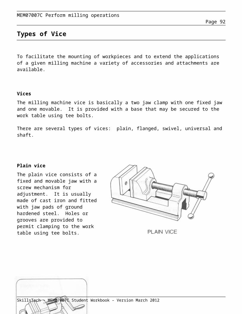
MEM07007C Perform milling operationsPage 92
Orientating the cutter : The cutter must be orientated correctly to ensure conventional milling occurs in relation to the direction of cut for the helix angle required.
Table traverse: The table traverse must be checked that it is parallel to the machine column prior to centralising the cutter to ensure accuracy.
The drive key The drive key must be positioned appropriately on the horizontal arbor. If the key is thinner than the cutter cross section it should be placed between the cutter and the arbor locknut. If the key is the same size or thicker than the cutter cross section it should be placed under the cutter.
Centralising the cutter
When centring a cutter on a round work piece when the cutter will not reach the centre of the work piece a common method of centring the cutter with the work piece is to:
Visually centralise the work under the cutter.
Set the stock of a try square with its blade against the work piece.
Measure the distance between the side of the cutter and the blade with an appropriate measuring device depending on the accuracy desired.
eg rule, callipers, vernier or slip gauges.
Set the square similarly on the other side of the work piece.
Measure the distance from the cutter side to the blade. The readings should be the same. If they are different, Using the cross feed handle, move the table an amount equal to half the difference in the two measurements.
SkillsTech – MEM07007C Student Workbook – Version March 2012
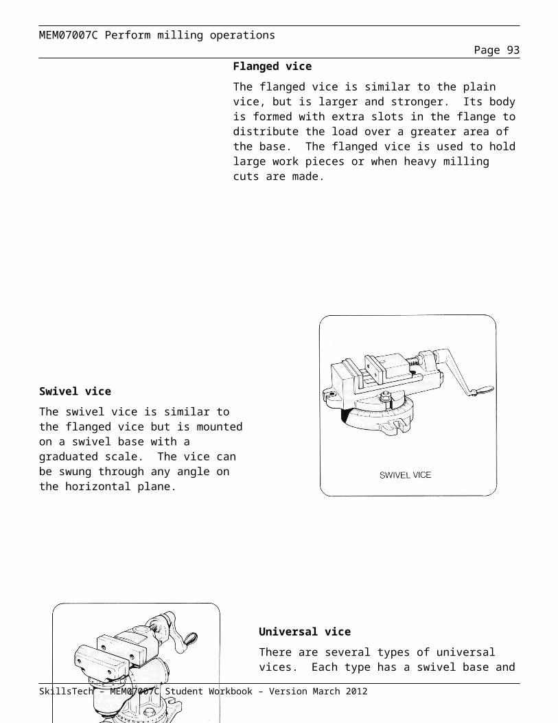
MEM07007C Perform milling operationsPage 93
Dividing Heads
Direct indexing head
The direct indexing head consists of a housing, a spindle with a driving lug and an indexing crank.
The rear of the housing is fitted with a flat index plate which has a number of holes spaced around the circumference of circles of different radii. The number of holes varies from circle to circle.
How it works
The handle of the indexing crank, which can be moved radially, is fitted with a spring loaded index pin. The index pin engages with the holes in the indexing plate.
The number of holes in the circles may be for example, 25, 28, 30, 34 and 40. If seven equally spaced positions need to be machined on a work piece the 28 hole circle would be used (28/7 = 4). The indexing pin would therefore be placed in every fourth hole as the machining progressed. Care must be taken to count the first hole as zero, and to count spaces not holes.
The workpiece can be setup in a chuck on the indexing head spindle or between centres using the indexing head and a mating tailstock. Any suitable bent tail carrier engaged into the slot of the drive plate may be used to rotate the workpiece for centre to centre work.
After the milling operation is complete in the first position the indexing pin is withdrawn and moved the appropriate number of holes (spaces) to begin the next milling operation. The indexing crank is attached directly to the spindle and the
SkillsTech – MEM07007C Student Workbook – Version March 2012

MEM07007C Perform milling operationsPage 94
spindle will move through the same angle with the work piece. The workpiece is turned around the circle until all the required cuts have been taken.
SkillsTech – MEM07007C Student Workbook – Version March 2012
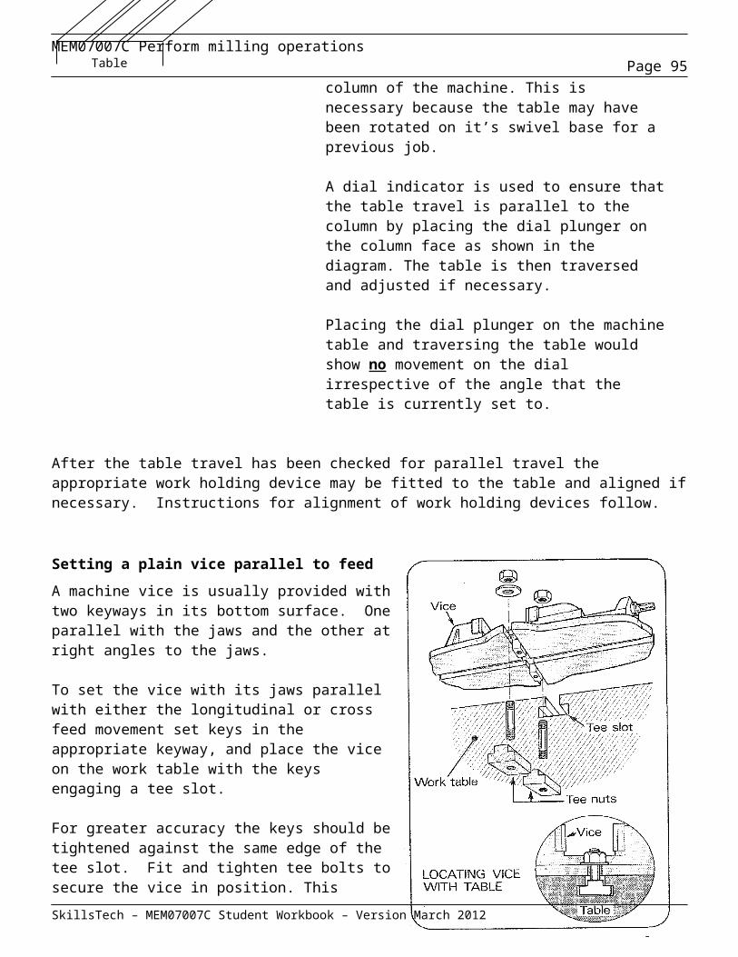
MEM07007C Perform milling operationsPage 95
Simple indexing head
The simple indexing head is similar in principle to the direct indexing head. The main difference is that the indexing crank is connected to the spindle through a worm and worm wheel usually at a ratio of 40:1.
To accommodate the worm gear the index plate is mounted at the side of the head. It has different sets of holes on each side and can be reversed as necessary to present a particular circle of holes to the index pin. The index plate may also be exchanged for another to facilitate different angular requirements and more accuracy as required.
Normally it is fitted with a direct index plate and index pin at the front end of the spindle. Before moving the indexing crank to the next position it is advisable to set the vector arms so they can be used as a guide to the next position.
With the worm gear disengaged the plain head may be used for direct indexing. This is useful for repetitive work with simple divisions and where great accuracy is not required.
Universal indexing head
The universal indexing head has the same operating parts as the simple indexing head. Part of its body forms a swivel block clamped in a cradle. The spindle can be tilted vertically through 90˚ or more.
The universal index head design permits power drive by way of gearing to the lead screw to the spindle so that helixes may be cut on the milling machine.
SkillsTech – MEM07007C Student Workbook – Version March 2012
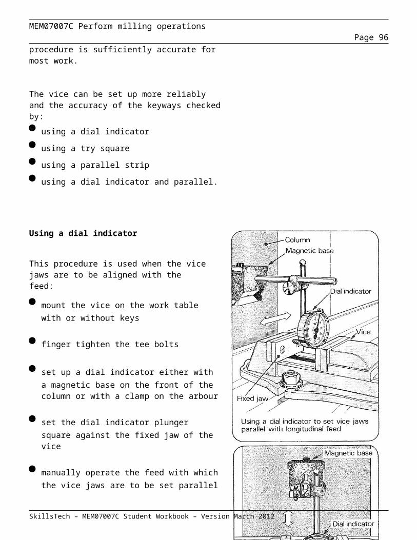
MEM07007C Perform milling operationsPage 96
Work holding with Indexing Heads
When an indexing head is to be used the two most common methods of work holding are Between Centres or in a chuck. Below are examples of work holding when using indexing heads.
Work held between centres
Work held in a Three Jaw chuck
SkillsTech – MEM07007C Student Workbook – Version March 2012
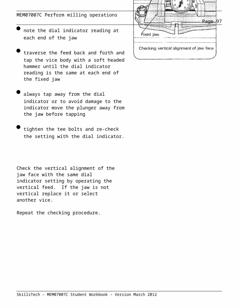
MEM07007C Perform milling operationsPage 97
Calculations for Indexing
Direct Indexing calculations
Example 1. Two keyways are to be machined on a shaft at 180o. A direct indexing head with a 24 hole circle is to be used to machine the keyways. If the crank arm pin is positioned in hole No.1 for the first keyway, what is the hole number for the second keyway?
Solution: Step 1. Calculate the total number of equal divisions.
360o 180o = 2 equal divisions
Step 2. Calculate the number of spaces between equal divisions (number of holes in plate number of divisions)
24 holes 2 divisions = 12 holes spaces per division
Step 3. Calculate the hole number for each machining position. (Current hole position + hole spaces to be added)
(First hole) 1 + 12 = 13
Answer: Hole No.13
SkillsTech – MEM07007C Student Workbook – Version March 2012

MEM07007C Perform milling operationsPage 98
Example 2. A hexagon drive is to be machined on the end of a shaft. A direct indexing head with a 36 hole circle is to be used to machine the drive. If the crank arm pin is positioned in hole No.1 for the first flat, what is the hole number for the fifth flat?
Solution: Step 1. Calculate the number of spaces between equal divisions (number of holes in plate number of divisions)
36 holes 6 divisions = 6 holes spaces per division
Step 2. Calculate the hole number for each machining position. (Current hole position + hole spaces to be added)
(First hole) 1 + 6 = 7(Second hole) 7 + 6 = 13(Third hole) 13 + 6 = 19(Fourth hole) 19 + 6 = 25(Fifth hole) 25 + 6 = 31
Answer: Hole No.31
SkillsTech – MEM07007C Student Workbook – Version March 2012

MEM07007C Perform milling operationsPage 99
Simple Indexing calculations
Simple indexing is used for divisions beyond the range of direct indexing.
The number of turns or part turns of the crank needed to cut the required number of divisions is calculated by the formula;
Number of crank turns = 40 (Where N is the number of equal divisions required) N
When the number of divisions required does not divide evenly into 40, the crank must move a fraction of a turn. This is achieved with the use sector arms on index plates. The sector arms can be moved, which allows for fractional (or part revolutions) of a full circle.
In the index plate example shown, the sector arms are set to have seven “spaces” of movement between the sector arms. (The number of holes is eight of which one hole would be filled by the crank arm plunger.)
The setting in the example represents a fractional turn of 7 34
Index plates have many option of “hole circles” into which the plunger pin of the crank handle locates for fractional indexing. There are two systems of index plates commonly available for milling machines.
The “Brown and Sharp” system has three index plates, with each plate having six “hole circles”.
Plate No.1 15, 16, 17, 18, 19, 20Plate No.2 21, 23, 27, 29, 21, 33Plate No.3 37, 39, 41, 43, 47, 49
The “Cincinnati and Parkinson” system has only one plate with 11 “hole circles” on each side of the plate.
Side No.1 24, 25, 28, 30, 34, 57, 38, 39, 41, 42, 43Side No.2 46, 47, 49, 51, 53, 54, 57, 58, 59, 62, 66
SkillsTech – MEM07007C Student Workbook – Version March 2012
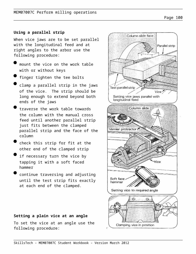
MEM07007C Perform milling operationsPage 100
Example 1. Calculate the simple indexing settings for indexing 18 even divisions.
Solution for example 1 with the Brown and Sharp system: Number of turns = 40 N
= 40 18
= 2 4 18
Since the Brown and Sharp system has an 18 hole circle, the figure above represents 2 full turns and 4 spaces on an 18 hole circle.
Solution for example 1 with the “Cincinnati and Parkinson” system:
Because the “Cincinnati and Parkinson” system does not have an 18 hole circle, the 4 fraction must be 18
manipulated into an equivalent fraction that has a denominator the same as one of the “Cincinnati and Parkinson” holes circles.
4 = 2 = 12 18 9 54
Since the “Cincinnati and Parkinson” has a 54 hole circle, the figure above represents 2 full turns and 12 spaces on an 54 hole circle.
SkillsTech – MEM07007C Student Workbook – Version March 2012
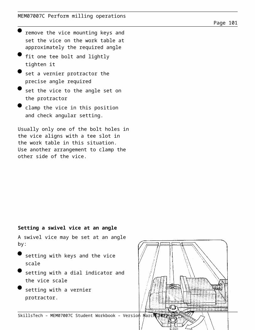
MEM07007C Perform milling operationsPage 101
Where the index requirements are expressed in terms of an angle a different formula is used.
Number of crank turns = Angle in degrees or Angle in minutes 9 540
Example 2. Calculate the indexing requirements for 39o using a Brown and Sharp dividing head.
Solution for example 2: Number of turns = Angle (degrees) 9
= 39 9
= 4 3 = 4 6 9 18
Since the Brown and Sharp system has an 18 hole circle, the figure above represents 4 full turns and 6 spaces on an 18 hole circle.
Example 3. Calculate the indexing requirements for 24o 36’ using a Cincinnati and Parkinson dividing head.
Solution for example 3: Number of turns = Angle (minutes) 540
= 24 o 36’ 540
= 1476’ = 41 540 15
= 2 11 = 2 22 15 30
Since the “Cincinnati and Parkinson” has a 30 hole circle, the figure above represents 2 full turns and 22 spaces on an 30 hole circle.
SkillsTech – MEM07007C Student Workbook – Version March 2012

MEM07007C Perform milling operationsPage 102
Review Questions – Setting workpieces, Cutters, Indexing
Question 1Describe two advantages of mounting a workpiece in direct contact with the milling machine table.
____________________________________________________________________________
____________________________________________________________________________
Question 2Explain the functional difference between clamps and stops.
____________________________________________________________________________
____________________________________________________________________________
___________________________________________________________________________
Question 3Describe the two different procedures for setting a cutter to a centreline of a job.
____________________________________________________________________________
____________________________________________________________________________
___________________________________________________________________________
____________________________________________________________________________
Question 4Explain how cutters should be stored and handled to ensure long life and safe working conditions.
____________________________________________________________________________
____________________________________________________________________________
____________________________________________________________________________
SkillsTech – MEM07007C Student Workbook – Version March 2012

MEM07007C Perform milling operationsPage 103
Question 5Explain the two situations that may exist when determining the position of a key when fitting a cutter to a horizontal arbor. ______________________________________________________________________________
______________________________________________________________________________
______________________________________________________________________________
______________________________________________________________________________
Question 6Explain how to set up a work piece in an accurately set vice on a milling machine table to produce a surface parallel to an existing machined surface.
______________________________________________________________________________
______________________________________________________________________________
______________________________________________________________________________
______________________________________________________________________________
Question 7 Describe how the alignment of a dividing head and tailstock be checked for accuracy. ______________________________________________________________________________
______________________________________________________________________________
______________________________________________________________________________
Question 8What is the difference between a Direct and a Simple indexing head? ______________________________________________________________________________
______________________________________________________________________________
______________________________________________________________________________
SkillsTech – MEM07007C Student Workbook – Version March 2012
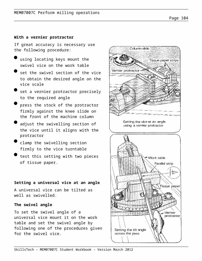
MEM07007C Perform milling operationsPage 104
Question 9 Using a Direct Indexing Plate with 24 slots, calculate the index movement for the following problems. (a) A square is to be machined on the end of a shaft.
(b) Three holes, equally spaced, need to be drilled in a spindle.
(c) Two flats, to fit a spanner, need to be machined onto a stud.
SkillsTech – MEM07007C Student Workbook – Version March 2012
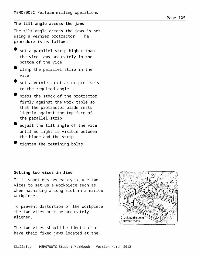
MEM07007C Perform milling operationsPage 105
Question 10Calculate the Simple indexing requirements to accurately index for the following divisions on a Brown and Sharp indexing head.
i 8 divisions ii 60 divisions
iii 11 divisions iv 24 divisions
v 108 divisions vi 56 divisions
vii 36 divisions viii 140 divisions
SkillsTech – MEM07007C Student Workbook – Version March 2012
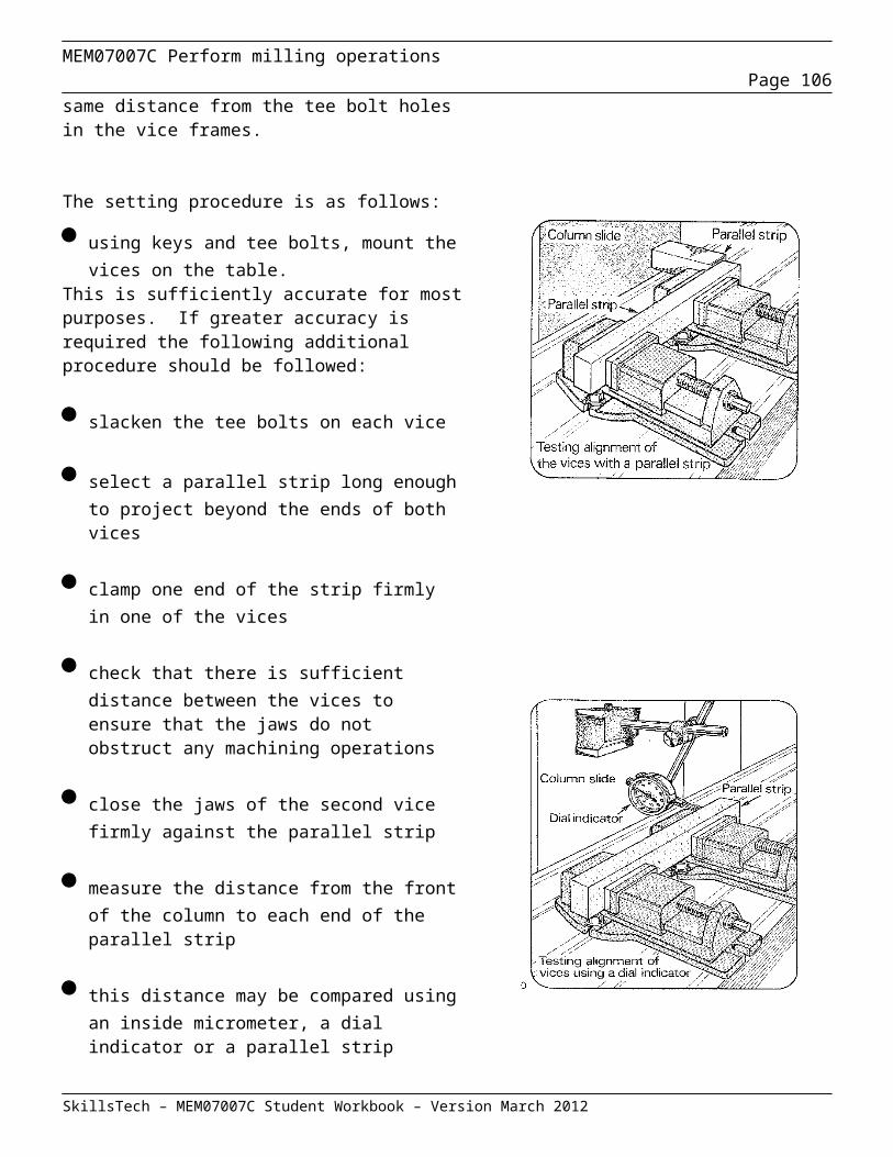
MEM07007C Perform milling operationsPage 106
Question 11Calculate the Simple indexing requirements to accurately index for the following angular displacements on a Brown and Sharp indexing head.
i 16o ii 30o
iii 50o iv 108o
Using the Cincinnati system v 36o 20’ vi 120o 30’
vii 5o 30’ viii 15o 30’
SkillsTech – MEM07007C Student Workbook – Version March 2012

MEM07007C Perform milling operationsPage 107
Types of milling operation
Milling cutters are used either individually or in combinations to machine various surfaces as described below and shown above.
Plain or Peripheral milling
Plain milling is the process of milling a surface that is parallel to the axis of the cutter and basically flat. It is done on plain or universal horizontal milling machines with cutters of varying widths that have teeth only on the periphery.
An example of this would be slab milling were a particularly wide cutter is used to produce a flat surface.
Other peripheral milling operations the teeth may be profiled to cut channels, grooves or other contours.
It can be carried out either on a horizontal machine or a vertical machine as shown in figure 16.
SkillsTech – MEM07007C Student Workbook – Version March 2012
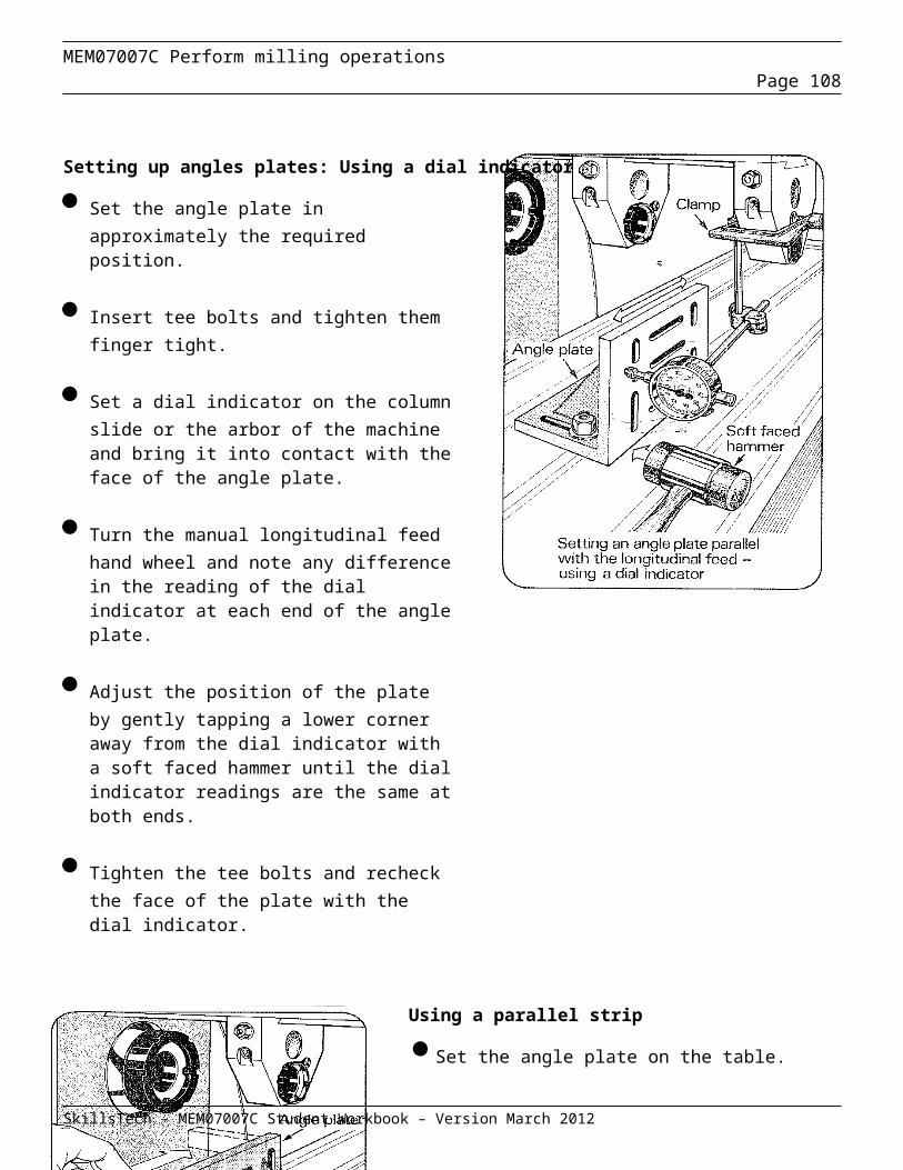
MEM07007C Perform milling operationsPage 108
End, Side or Face milling
End, Side or Face milling is where a cutter that has teeth on the periphery, and one or both sides are used. When a single cutter is being used, the teeth on both the periphery and sides may be cutting. The machined surfaces are usually either perpendicular or parallel to the spindle. Angle cutters can be used to produce surfaces that are at an angle to the spindle for such operations as making external dovetails or flutes in reamers.
Face cutting is usually rotated on a vertical axis but it is not uncommon to rotate the tool on the horizontal axis.
The teeth of some face milling cutters extend to the periphery of the cutter so that each tooth has two angular related cutting edges.
Plain cutters of this type may be used to remove large amounts of material from flat surfaces.
Alternatively the peripheral teeth of the cutter may be profiled to produce dovetails, tee slots or a wide range of other profiles.
Face milling cutters are also used in combination gang milling operations.
SkillsTech – MEM07007C Student Workbook – Version March 2012
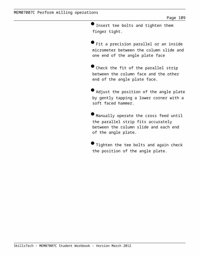
MEM07007C Perform milling operationsPage 109
End Milling
Straddle Milling
In a typical straddle milling set-up, two-side milling cutters are used. The cutters are half-side or plain side milling cutters, and have straight or helical teeth. Stagger-tooth side milling cutters can also be used.
A group of spacers is mounted in between two milling cutters on the spindle arbor as shown below, for the milling of two surfaces parallel to each other at a given distance.
Gang Milling
Gang milling is a horizontal milling operation that utilises three or more milling cutters grouped together for the milling of a complex surface in one pass. As illustrated below, different type and size of cutters should be selected for achieving the desire profile on the workpiece.
SkillsTech – MEM07007C Student Workbook – Version March 2012
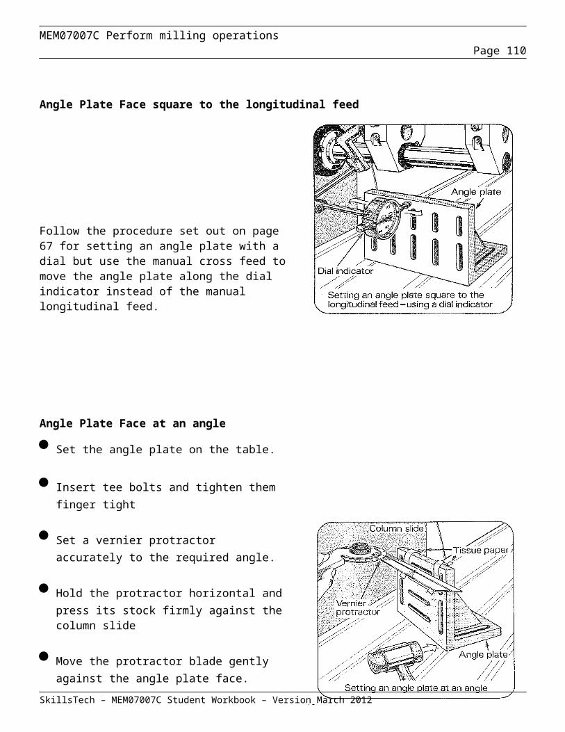
MEM07007C Perform milling operationsPage 110
Form Milling
Form milling is the process that uses a milling cutter with a unique shape to impart that shape onto the workpiece. A wide variety of standard form cutters exist and special form cutters may be produced for use in one off or special applications.
Examples of form cutters are displayed below.
Double Angle Cutter Single Angle Cutter
T Slot Cutter Dovetail Cutter
SkillsTech – MEM07007C Student Workbook – Version March 2012
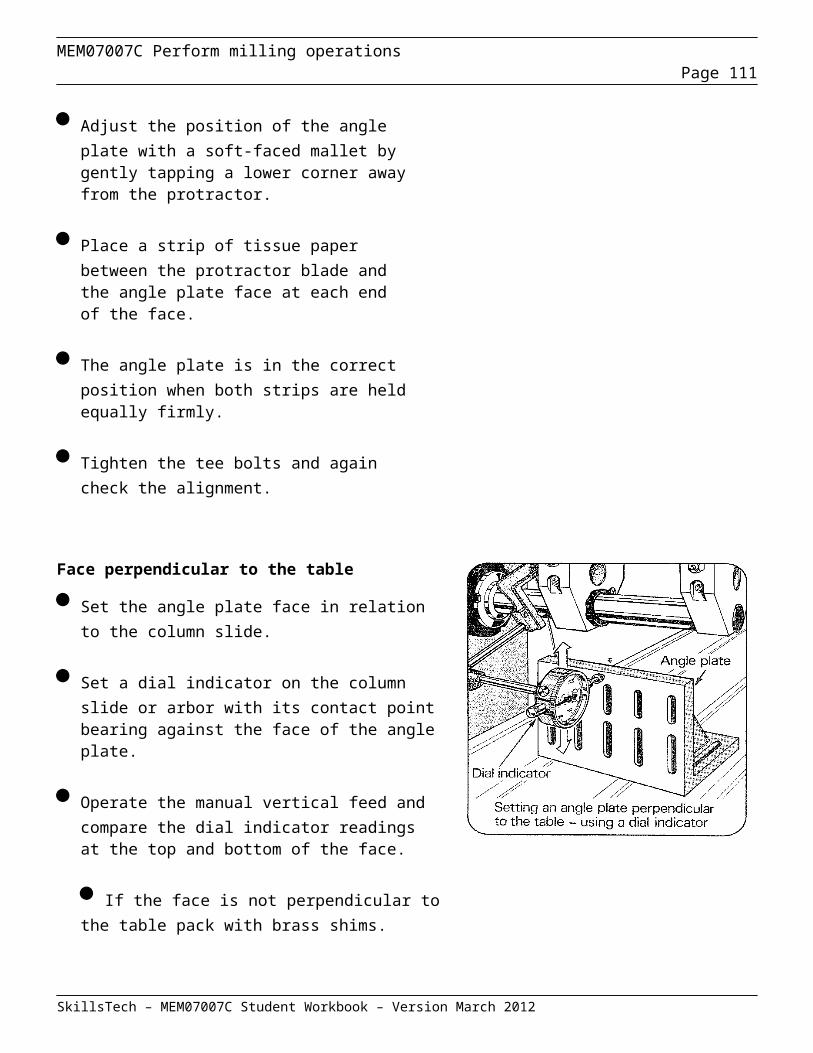
MEM07007C Perform milling operationsPage 111
Direction of Feed
It is usually regarded as standard practice to feed the work piece against the milling cutter. When the work piece is fed against the milling cutter, the teeth cut under any scale on the work piece surface and any backlash in the feed screw is taken up by the force of the cut.
As an exception to this recommendation, it is advisable to feed with the milling cutter when cutting off stock or when milling comparatively deep or long slots. The direction of cutter rotation is related to the manner in which the work piece is held.. No milling cutter should ever be rotated backward; this will break the teeth. Never change feeds while the cutter is rotating.
SkillsTech – MEM07007C Student Workbook – Version March 2012
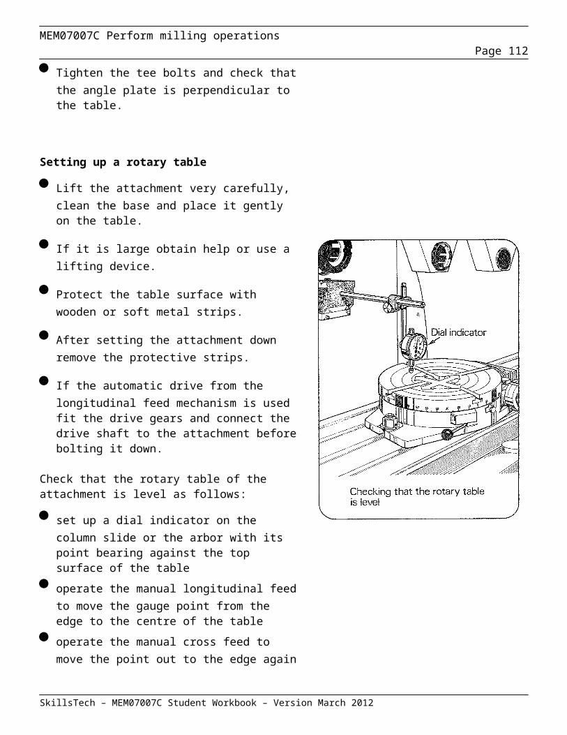
MEM07007C Perform milling operationsPage 112
Milling machine attachments
Milling machine operations and applications can be enhanced by the use of various attachments used in conjunction with the fundamental features of the machine.
Vertical attachment
The vertical attachment is designed to mount on the column and be driven by the spindle of plain or universal milling machines. It is used to perform milling operations which would otherwise need to be performed on a vertical milling machine.
The attachment consists of a housing, a spindle head and bevel drive gears with a ratio of 1:1. The spindle has a standard taper and drive lugs for cutters.
The spindle housing has a swivel mechanism to permit the spindle to be angled with respect to the table of the milling machine. A graduated scale is fitted to the housing to assist in setting the desired angle. A locking mechanism is provided to hold the attachment at the selected angle.
High speed attachment
The high speed attachment is used to drive small milling cutters at high speeds. The attachment consists of a housing containing step-up gearing and a small spindle. It may be fitted to operate in either the horizontal or vertical plane.
SkillsTech – MEM07007C Student Workbook – Version March 2012
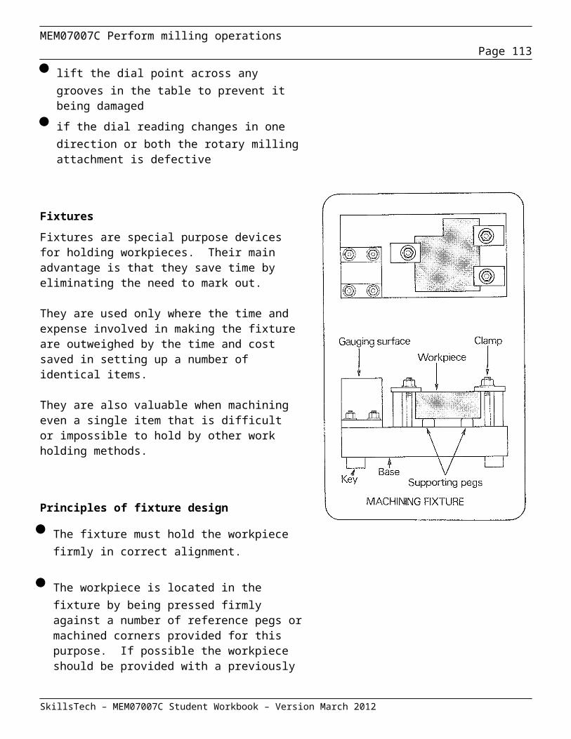
MEM07007C Perform milling operationsPage 113
Universal spiral attachment
The universal spiral attachment is used when milling spirals with a plain milling machine.
It consists of a housing fitted with a swivel plate for mounting on the face of the milling machine column. The body may then be swivelled about the axis of the machine spindle. The attachment is fitted with a small spindle rotated by the machine spindle through gearing in the housing. The small spindle is also capable of swivelling with respect to the housing.
The combination of the two swivelling actions permits the small spindle to be set at any compound angle in relation to the column of the machine.
This attachment is particularly useful for cutting helical threads, gears and racks.
Motorised overarm attachment
This attachment is fitted on the column in place of the milling machine overarm.
It consists of a reversible electric motor, a gearbox and a double swivel head fitted with a standard spindle driven by the motor through the gearbox.
End mills, face mills, collets and other tools and adaptors may be fitted in the spindle and set at any desired angle. In some cases the spindles of the attachment and the machine may both be used simultaneously in complex milling operations.
SkillsTech – MEM07007C Student Workbook – Version March 2012
MEM07007C Perform milling operationsPage 114
Slotting attachment
The slotting attachment is used to provide a reciprocating motion to drive a single point cutting tool. It may be used for cutting at any angle in the vertical plane to produce keyways, slots and corners.
The attachment is designed to mount on the milling machine column and houses a bull wheel and crank mechanism driven by the machine spindle to produce the necessary reciprocating motion. The stroke length may be adjusted and tool head swivelled about the spindle axis through 360˚.
Circular table attachment
The purpose of this attachment is to enable a plain milling machine to be set up for operations which would otherwise require a machine with a rotary table. It may be fitted to plain, universal or vertical machines.It is used for profile milling, facing off of quantities of small pieces in one setup, and many other circular operations in the horizontal plane such as slotting and dovetailing.
Circular attachments consist of a base, worm gear drive mechanism and a small circular work table.The base is bolted to the work table of the milling machine and the drive mechanism is connected to the feed mechanism of the machine. A manual feed crank handle is also provided.
The workpiece is secured to the circular work table and the table is then rotated by the feed mechanism for circular cuts. By combining the rotary motion with one of the other machine feeds, it is possible to produce most shapes or profiles.
SkillsTech – MEM07007C Student Workbook – Version March 2012
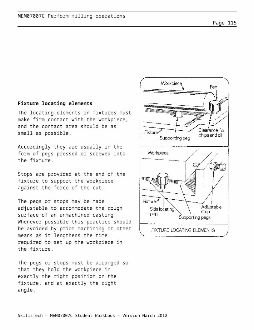
MEM07007C Perform milling operationsPage 115
The hand crank may be replaced by an indexing device for work requiring accurately spaced slots, holes or grooves. The circular milling attachment is converted into a large indexing head in the manual mode.
Rack attachment
The rack attachment is designed to mount between the face of the column and the outer support on a plain milling machine.
The attachment has a fixed housing fitted with an angle drive and a spindle. The spindle axis is fixed parallel to the work table.
In rack milling, the cross feed is used to move the cutter into the work piece, and the longitudinal feed is used to index the cutter to produce the rack teeth. In order to achieve this indexing with the degree of accuracy needed a special rack indexing attachment is used.
The indexing attachment is fitted to one end of the table and the bracket carries a locking indexing wheel together with change gears for gearing the table feed screw. During the indexing operation the correct gearing is selected, the locking pin is withdrawn and the table is advanced by turning the table feed screw until the pin drops into the next slot and locks the wheel in position. This method is more reliable than relying on graduations on a dial.
A universal or spiral attachment can be used to expand the scope of the rack attachment to include operations such as milling the undercut teeth of a broach.
Special vices with long jaws and bases are available for use in rack cutting operations.
SkillsTech – MEM07007C Student Workbook – Version March 2012

MEM07007C Perform milling operationsPage 116
Review Questions – Milling operations , Milling machine attachments
Question 1 Various attachments are available for extending the capabilities of milling machines. Name the accessories which should be used to carry out the following operations:
cutting rack teeth ______________________________________________________________
cutting a thread _______________________________________________________________
cutting a keyway _______________________________________________________________
cutting gear teeth _______________________________________________________________
Question 2What is the common name for a single point cutter and when is it used?
_________________________________________________________________________________
_________________________________________________________________________________
Question 3Name and describe five types of milling operation, listing two types of cutter used for the operation.
i _________________________________________________________________________________
_________________________________________________________________________________
_________________________________________________________________________________
SkillsTech – MEM07007C Student Workbook – Version March 2012
MEM07007C Perform milling operationsPage 117
_________________________________________________________________________________
_________________________________________________________________________________
ii _________________________________________________________________________________
_________________________________________________________________________________
_________________________________________________________________________________
_________________________________________________________________________________
_________________________________________________________________________________
iii _________________________________________________________________________________
_________________________________________________________________________________
_________________________________________________________________________________
_________________________________________________________________________________
_________________________________________________________________________________
iv _________________________________________________________________________________
_________________________________________________________________________________
_________________________________________________________________________________
_________________________________________________________________________________
_________________________________________________________________________________
v _________________________________________________________________________________
_________________________________________________________________________________
_________________________________________________________________________________
_________________________________________________________________________________SkillsTech – MEM07007C Student Workbook – Version March 2012
MEM07007C Perform milling operationsPage 118
_________________________________________________________________________________
Question 4 "Normal" or "up-cut" and "Climb" or "down-cut" are 2 types milling processes. With the aid of sketches explain these two processes and explain two advantages and two disadvantages of each.
Normal" or "up-cut"
Advantages ____________________________________________________________________________
______________________________________________________________________________________
Disadvantages __________________________________________________________________________
______________________________________________________________________________________
"Climb" or "down-cut" milling
Advantages ____________________________________________________________________________
______________________________________________________________________________________
SkillsTech – MEM07007C Student Workbook – Version March 2012

MEM07007C Perform milling operationsPage 119
Disadvantages ___________________________________________________________________________
_____________________________________________________________________________
Section 6 – Check components for conformance with specifications
This section contributes to the underpinning knowledge required for the successful completion of the following criteria:
7.6AA.5.1 - Components checked for conformance with specification using appropriate techniques, tools, and equipment
Introduction
Each operator is responsible for the quality of the work they produce. An essential step in ensuring quality is in checking that any component/s produced conform to the required customer specification at each step of manufacture. It is far easier to detect and prevent defects at this point before the components/s not meeting the specification are assembled or despatched. This helps prevent scrap, returns, and rework which is costly.
The following topics will be covered in this section:
Direct measurement tools Comparative measurement tools Recording size conformance
Direct measurement tools
There is many tools available to measures sizes directly on a component to check if they conform to specifications. They should have been encountered previously in other Units of competency such as MEM0120232A - Perform engineering measurement, MEM07005B - Perform general machining and MEM18003C – Use tools for precision work.
SkillsTech – MEM07007C Student Workbook – Version March 2012

MEM07007C Perform milling operationsPage 120
The following pages display a variety of tools that can be used to obtain sizes of components by direct measurement.
VERNIER CALIPERS
Vernier Callipers
A vernier is a device fitted to some measuring tools to enable accurate measurements to be made. The vernier consists of two scales:
main scale vernier scale.
The main scale is graduated into standard divisions similar to a graduated rule. On the other hand, the vernier scale is made to a length that when it is divided into a number of equal parts, each part represents a proportional length of the corresponding main scale division.
Vernier callipers are designed in such a way they are able to take external, internal and depth measurements, and can be used in locations such as narrow slots that are inaccessible to micrometers. Micrometers however are in many cases preferred, as a greater degree of skill is required to obtain consistently accurate readings using a vernier calliper.
When you have finished using the vernier, it is essential that it is wiped clean, lightly oiled with a suitable protective oil and stored in a protective box.
Using a Vernier Calliper
The procedure for using a Vernier calliper is as follows:a) Move the sliding jaw to the approximate positionb) Lightly tighten the locking screw on the fine
adjustment clamp.c) Adjust the sliding jaw by means of the knurled fine
adjustment nut until; with the instrument square to the work piece, the jaws contact the work piece with a sensitive feel.
d) Lightly tighten the locking screw on the sliding jaw.
SkillsTech – MEM07007C Student Workbook – Version March 2012

MEM07007C Perform milling operationsPage 121
In general, the precautions against strain, misuse and faulty storage applying to micrometers are also essential for Vernier callipers.
SkillsTech – MEM07007C Student Workbook – Version March 2012
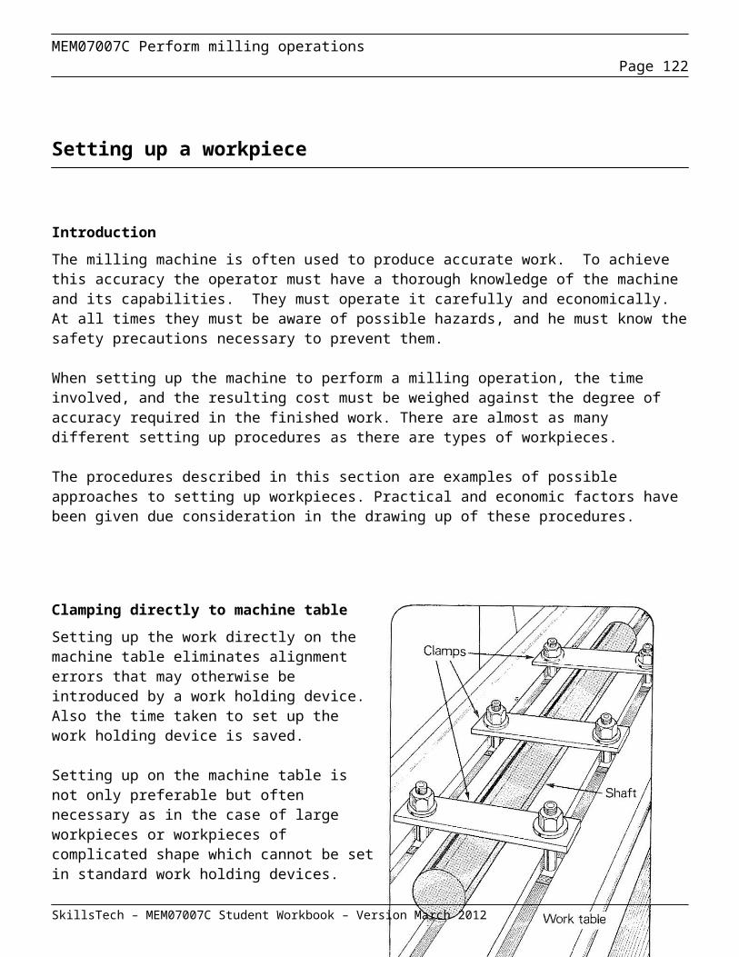
MEM07007C Perform milling operationsPage 122
VERNIER HEIGHT GAUGE
The vernier height gauge is a development of the vernier calliper. The graduated frame is held in a vertical position by being attached to an accurately ground base.
The vernier is read in the same way as the vernier calliper, except in this case the reading is taken from the movable jaw to the base.
The gauge is used from a surface plate or table and is designed for accurate marking out or checking heights.
DIAL TYPE CALIPERS
These are callipers with a dial face-reading device that replaces the vernier scale.
They will measure with the same accuracy as the vernier type. The dial gives the advantage of quick and easy reading.
The dial is graduated to represent a proportion of the main scale division. One complete turn of the pointer represents a distance of one division on the main scale.
Reading a dial calliper is carried out as follows:
Note the number of main divisions to the left of the movable jaw.
Read the dial and add the additional readings to the main scale.
SkillsTech – MEM07007C Student Workbook – Version March 2012
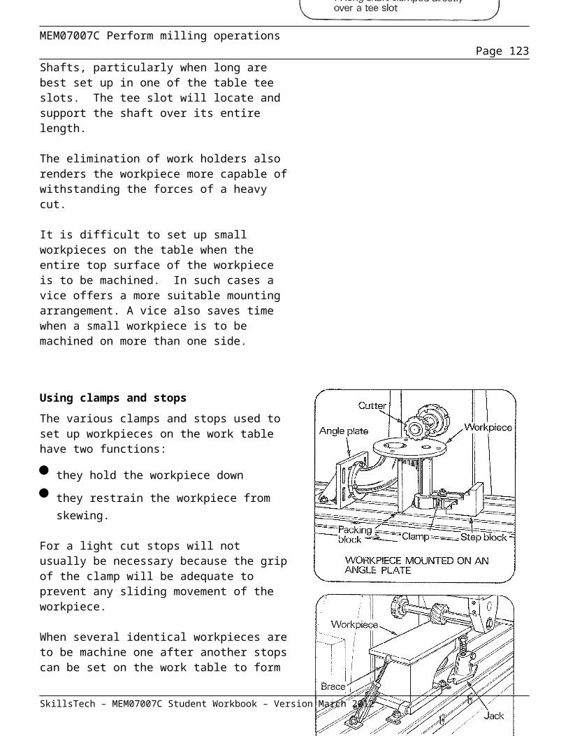
MEM07007C Perform milling operationsPage 123
DIGITAL LIQUID DISPLAY VERNIER
Digital readout verniers are the easiest of all to read; some types can be plugged straight into the computer
which keeps a record of all measurements made. Most makes can convert metric to imperial at the touch of
a button.
THE OUTSIDE MICROMETER
Outside micrometers are used to measure outside diameters, thicknesses of material and lengths of parts. The principle of the micrometer is based on the movement of a precision-cut screw through a mating nut. The
scales on the micrometer are a means of counting the revolutions of the screw and converting them into length measurement.
Metric micrometers measure in 0.01mm intervals and Imperial micrometers measure in intervals of 0.001”. Where greater accuracy is required, a vernier scale is
provided on the micrometer, enabling measurements to 0.001mm or 0.00001”
They are available in various sized frames. Metric micrometers come in sizes from 0-25mm, 25-50mm, 50-75mm, 75-100mm,
100-125mm, 125-150mm and beyond.Imperial micrometers range in size from 0-1”, 1-2”, 2-3”, 3-4” and
beyond. All metric sizes however, have a measuring range limited to the length of the thread on the spindle. The range is 0 - 25mm.
Similarly an Imperial micrometer has a range limited to 1” of travel in the spindle.
SkillsTech – MEM07007C Student Workbook – Version March 2012
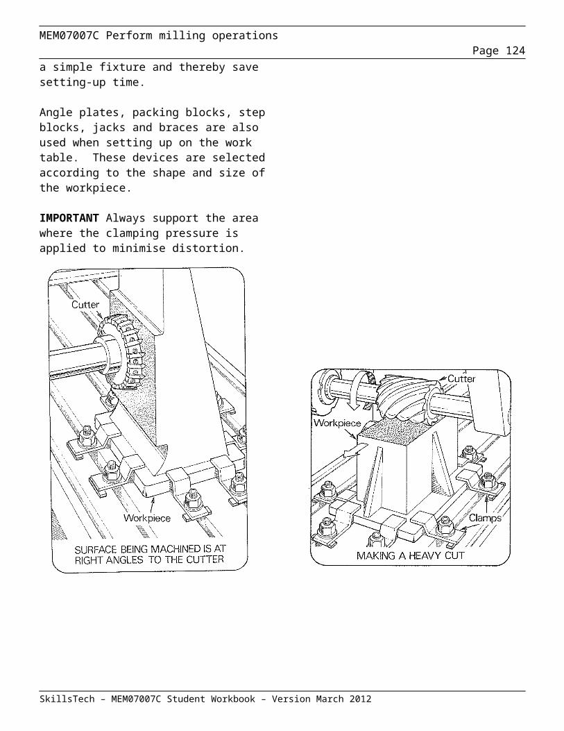
MEM07007C Perform milling operationsPage 124
CARE OF MICROMETERS
Micrometers should always be checked for accuracy – never assume that a micrometer is accurate. Check the thimble for play or looseness and tighten the adjusting nut. Always remember that a micrometer is a precision instrument, not a G-clamp. In summary the following rules should always be applied when caring for micrometers:
Clean the face of the spindle and anvil before using the micrometer Check the zero reading Ensure the work is clean and dry Do not attempt to measure over rough surfaces Work should be stationary before attempting to take reading Do not screw the spindle beyond the barrel scale Avoid micrometer from coming into contact with dirt and cutting fluids Never allow the micrometer to be exposed to heat Never apply excessive force to the thimble Don't put micrometers down in a position where it could be knocked or dropped Have micrometers checked regularly When not in use have them stored in a protective box.
Using Outside Micrometers
Excessive pressure during adjustment will give inaccurate readings, cause strain on the thread and distort the frame. To avoid this problem, micrometers are fitted with a spring-loaded ratchet that will ensure constant adjusting pressure on the component being measured provided the micrometer is kept square to the work.
When using the micrometer, try as much as possible to have the graduations on the main scale towards you. If the frame cannot be supported by the left hand and only one hand can be used to hold the micrometer, support the frame on the lower centre of your palm using the little finger to hold the frame to the palm. Keep the first finger and thumb free to adjust the knurled thimble.
SkillsTech – MEM07007C Student Workbook – Version March 2012
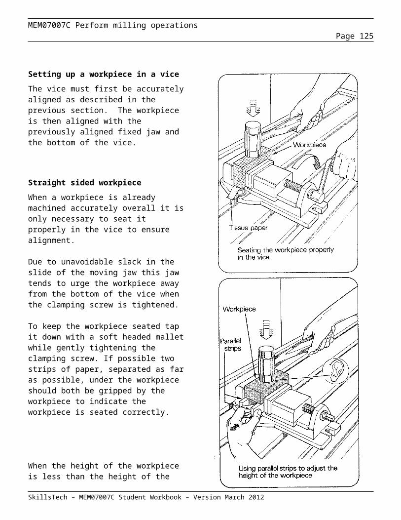
MEM07007C Perform milling operationsPage 125
INSIDE MICROMETERS
Inside micrometers are used for measuring internal diameters and distances between parallel surfaces. However, the construction of an inside micrometer does not allow it to be used to measure a hole smaller than the overall length of the micrometer barrel and its anvils. To measure smaller diameter holes a telescopic bore gauge can be used.
The micrometer is provided with a series of extension rods to measure a range of sizes.
When using an inside micrometer to measure the diameter of a hole, fit an extension rod to suit the size of the hole being measured.
Then by holding the body of the micrometer between the finger and thumb of your right hand, support the other end with the thumb and finger of your left hand.
With the extended anvil as a pivot, move the body of the micrometer through the hole. Turning the micrometer thimble with your thumb and finger until you feel the anvil just touching against the surface. Pass the anvil through the hole several times to ensure that a measurement is being taken directly through the centre. When the feel is satisfactory, lift the micrometer from the hole and read the size indicated on the micrometer. Add this size to the rod length to obtain the overall size of the hole.
SkillsTech – MEM07007C Student Workbook – Version March 2012
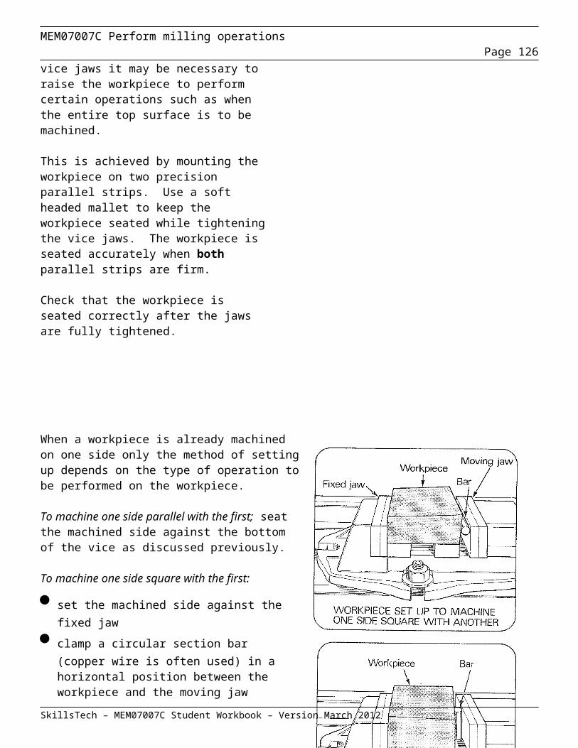
MEM07007C Perform milling operationsPage 126
BORE MICROMETER
Bore micrometers are used to precisely measure internal bores to 0.01mm tolerance, they are self centring & self aligning internal micrometers that range from 3.5mm up to 300mm
Calibrating the bore gage requires the use of accurately ground check rings (ring masters) before commencing measurements.
TUBULAR INSIDE MICROMETER
Tubular micrometers are highly useful tools for internal linear measurements such as measuring cylinders, rings, setting callipers, comparing gauges, and measuring parallel surfaces.
The extension rods are made of steel tubing, light in weight, yet extremely rigid. Rods are approximately 3/8" (9.5 mm) diameter to meet the requirements of mechanics that prefer this larger diameter. By removing the hardened and ground anvil ends (end caps) of the micrometer head, the rods may be attached to either or both ends of the micrometer as preferred. Each rod may be individually adjusted for wear by the hardened and ground anvil at the end.
Rods attachable to either one or both ends of the head ensures the best balance, feel, and ease of reading
Tubular measuring rods are lightweight, yet extremely rigid. Rods are insulated, with the exception of 1/2" (13 mm) and 1" (25 mm) sizes
Each rod is marked with length Hardened and ground anvils on rods are adjustable for length. Head anvil is hardened and ground Interchangeable anvils on both 1/2" (13 mm) and 1" (25 mm) heads Quick reading figures – every thousandth numbered on Inch reading tools Lock nut furnished on 1" (25 mm) heads
SkillsTech – MEM07007C Student Workbook – Version March 2012

MEM07007C Perform milling operationsPage 127
DEPTH MICROMETER
Depth micrometers have been designed to measure depths of holes, depths of grooves or recesses and heights of shoulders or projections. The measuring range of depth micrometers can be increased by using interchangeable extension rods.
The graduations on depth micrometers are reversed to the scale of outside micrometers. This means the readings are covered by the thimble as the micrometer is extended.
SPECIAL PURPOSE MICROMETERS
Some micrometers have anvils specially designed for a specific purpose, such as the measuring of: -
The wall thickness of tubing
The thickness of paper sheet
The pitch diameter of screw threads
Ask your trainer to show you any special purpose micrometers used at your work.
SkillsTech – MEM07007C Student Workbook – Version March 2012
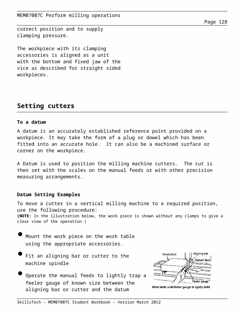
MEM07007C Perform milling operationsPage 128
DIGITAL MICROMETERS
These operate on a similar principle to other micrometers and they give a direct numerical reading of size on a dial in the frame.
The figures on the dial: -
Make the micrometer quick and easy to read
Ensure accurate measurement of size that
Help eliminate reading errors
MICROMETER SETS 0-150MM
Large outside micrometers with interchangeable extended anvils make it possible to measure over a range of sizes.The micrometer consists of the normal barrel, spindle and thimble with a larger frame.The anvil in the frame can be removed by undoing a clamping nut that holds it in position.By selecting suitable anvils it is possible to take measurements progressively larger from zero to the maximum range of the micrometer frame.Care must be taken when changing anvils.Make sure the locating face on the frame and the collar on the extended anvil are clean and free from grit.Test bars are supplied with the micrometer. Always make a test reading with a test bar between the anvils before you measure with the micrometer.
SkillsTech – MEM07007C Student Workbook – Version March 2012
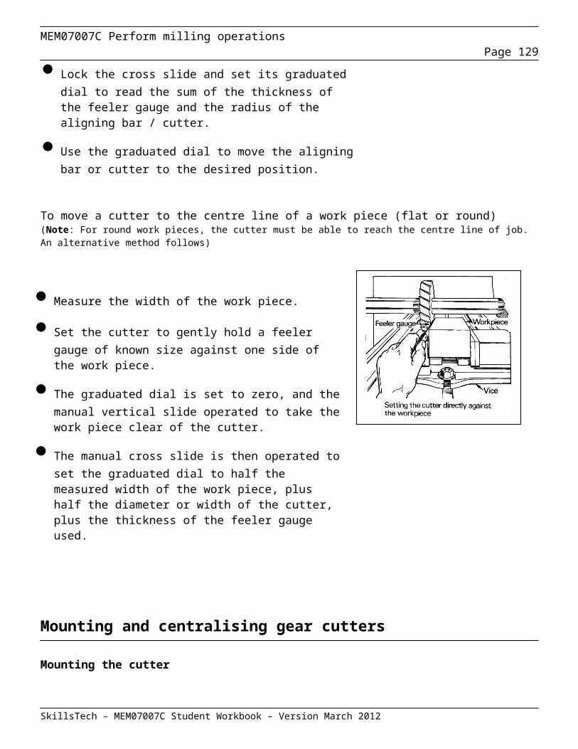
MEM07007C Perform milling operationsPage 129
Comparative measurement tools
Comparative measuring tools are often used
Gauge blocks
Metric & Imperial gauge blocks
Gauge blocks (also known as gage blocks, Johansson gauges, or slip gauges) are precision ground and lapped measuring standards. They are used as references for the setting of measuring equipment such as micrometers, sine bars, dial indicators (when used in an inspection role).
Shown at right is an image of a metric gauge block set; close examination of the set will show that the set consists of a range of varying size blocks, along with two wear blocks.
In use, the blocks are removed from the set, cleaned of their protective coating (petroleum jelly or oil) and wrung together to form a stack of the required dimension, with the minimum number of blocks. The wear pieces are included at each end of the stack whenever possible as they provide protection against damage to the lapped faces of the main pieces. After use the blocks are re-oiled or greased to protect their faces from corrosion.
Wringing is the process of sliding the two blocks together so that their faces lightly bond. When combined with a very light film of oil, this action excludes any air from the gap between the two blocks. The alignment of the ultra-smooth surfaces in this manner permits molecular attraction to occur between the blocks, and forms a very strong bond between the blocks along with no discernible alteration to the stack's overall dimensions.
SkillsTech – MEM07007C Student Workbook – Version March 2012
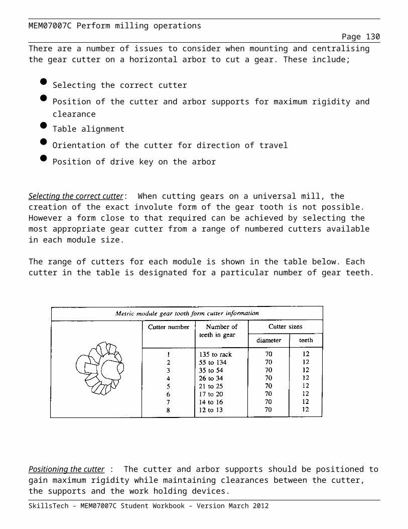
MEM07007C Perform milling operationsPage 130
GAUGES – SCREW PITCH, RADIUS, FEELER AND SQUARES
Gauges are used to perform simple measurement by comparing the item to be measured to a gauge. The gauge is manufactured to sizes that allow the user to quickly determine whether an item is accurate.
SCREW PITCH GAUGES . Screw pitch gauges – sometimes called thread pitch gauges are used by selecting a leaf of the gauge which appears to be a match to the thread being measured. Holding the selected leaf so that its teeth fit into the thread to be checked, the accuracy of the can be seen by sighting against a bright surface. When a leaf is found whose teeth fit snugly into the thread, the number stamped on the leaf will indicate the pitch of the thread. See the illustration on the right for the use of a pitch gauge when measuring an external thread. To determine the thread size you also need to determine the diameter of the bolt or hole. Using the diameter and thread pitch and referring to a Thread Pitch Chart (See Appendix) the bolt/hole size may be determined.
RADIUS GAUGERadius gauges (fillet gauges) also consist of thin steel blades which may be fastened together like a jack knife or pushed snugly into a folding case. Their profiles are used to check the size and accuracy of the radii of concave and convex corners and shoulders. Each blade fits one inside or outside radius, and is stamped with the radius size.
Find a gauge which fits the radius and read the size from the face of the blasé. To check close tolerances use an optical comparator.
SkillsTech – MEM07007C Student Workbook – Version March 2012

MEM07007C Perform milling operationsPage 131
FEELER GAUGES
Feeler gauges consist of good quality steel blades fastened together like a pocket knife, each blade accurately ground to the exact thickness, which is marked on the blade.
Feeler Gauges are used to measure small gaps, clearances, fits between matting surfaces and for checking flatness. One blade or a combination of many can be used to gain the correct size. Always surround the thin blade with heavier ones to avoid damage when using them. Do not force the gauges into the gap but develop a touch or feel by pulling the feelers.
GO & NO GO GAUGES
These gauges are made for simple pass/fail inspection
A Go No-Go gauge is a measuring tool that does not return a size in the conventional sense, but instead returns a state. The state is either acceptable (the part is within tolerance and may be used) or it is unacceptable (and must be rejected).
Basically there are two separate or combined gauges for each feature to be measured.
One gauge must fit inside the feature, and the second must not. In other words the GO gauge must fit inside/outside the feature, the NO GO gauge must not. If the GO gauge does not fit, the tolerance is above the maximum metal tolerance. If the NO GO gauge goes, the feature is below the minimum metal tolerance.
This method is best suited to unskilled operators testing many parts.
This method can also be used for inspection rooms, and limited runs using gauge blocks.
They are well suited for use in the production area of the factory as they require little skill or interpretation to use effectively and have few, if any, moving parts to be damaged in the often hostile production environment.
SkillsTech – MEM07007C Student Workbook – Version March 2012
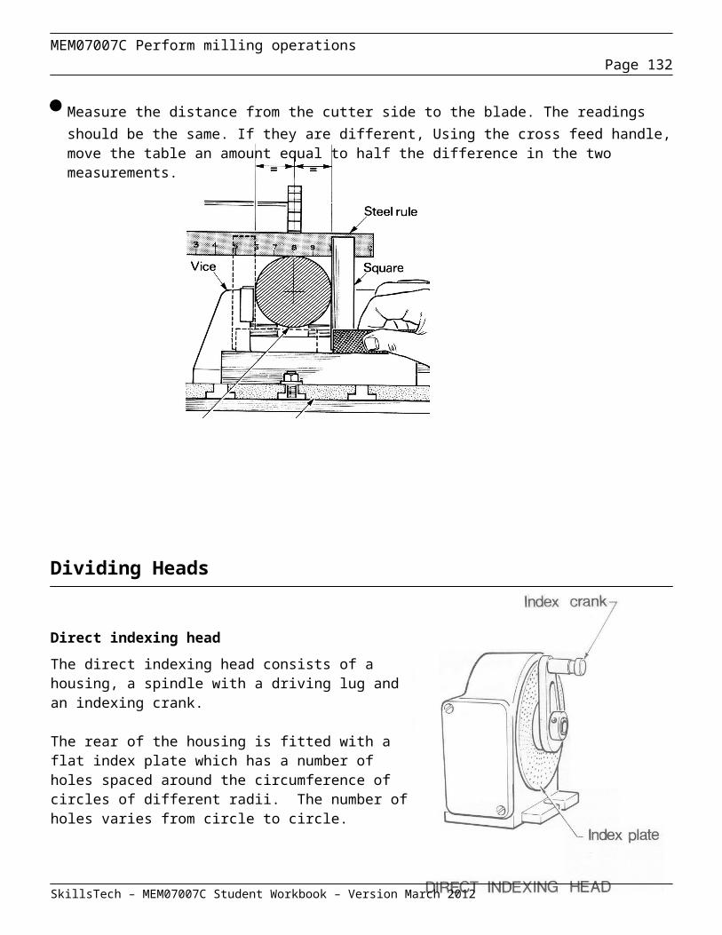
MEM07007C Perform milling operationsPage 132
GO/NO GO THREAD GAUGES, INTERNAL & EXTERNAL
TAPER PLUG GAUGE
This is a checking device for measuring if you have machined a taper to the correct size as indicated by the drawing on the left.
GAP GAUGES
These images illustrate an alternative type of gauge. The gap gauge has four anvils or jaws, the first one or pair (outermost) are set using the upper limit (tolerance) of the part and the inner set adjusted to the lower limit of the part.
The usage of this gauge may be more intuitive than the plug type. A correctly machined part will pass the first set of jaws and stop at the second — end of test. In this manner a part may be checked in one action, unlike the plug gauge that needs to be used in the correct sequence and flipped to access the second gauge. The left image is a plain gap gauge used to measure outside distances (diameters); the right hand image shows two views of a thread gap gauge.
Once the concept is understood, the principle of operation can lead to all manner of designs where internal grooves, keyways, splines etc. may be measured in a simple yet effective manner. These will often be made to order by the toolmakers, or a related skilled tradesman.
SkillsTech – MEM07007C Student Workbook – Version March 2012
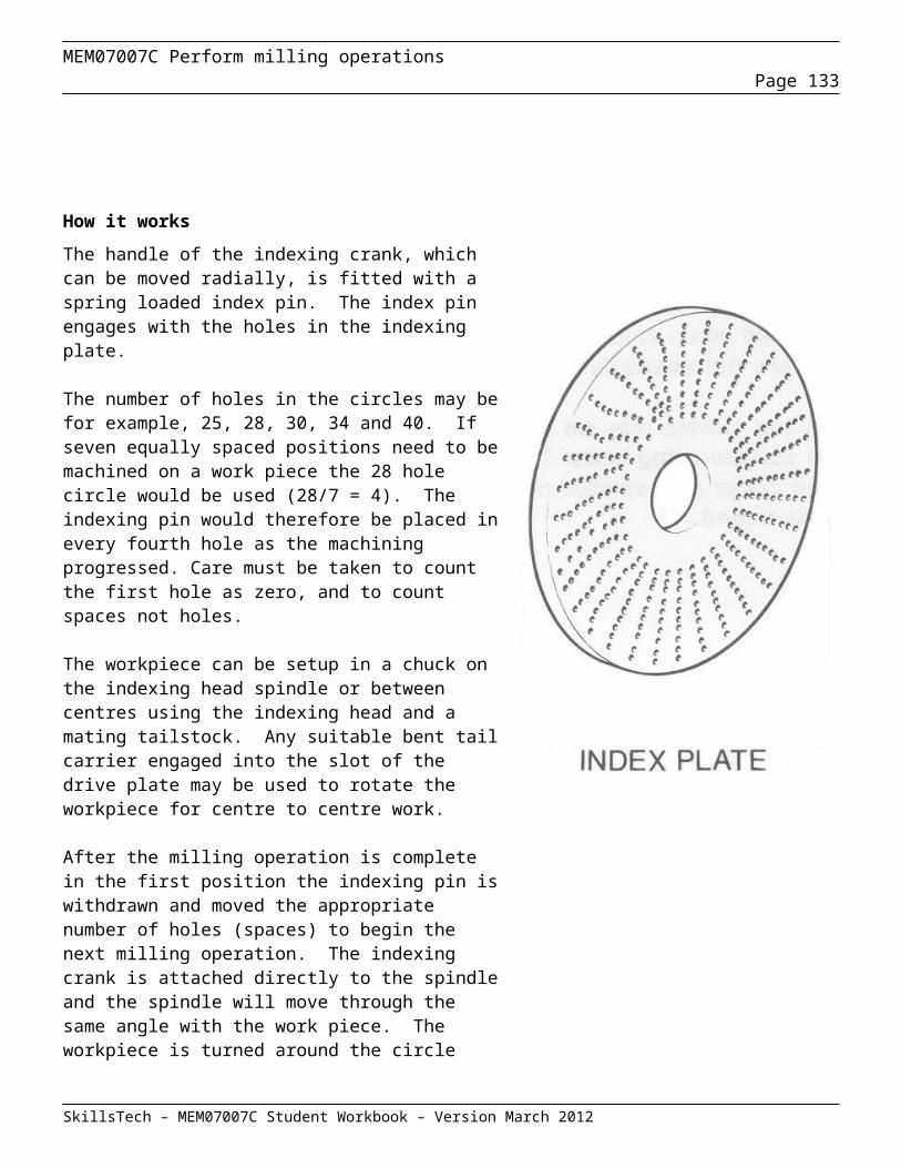
MEM07007C Perform milling operationsPage 133
FORM GAUGE
A form gauge consists of a good-quality steel bar finished to high standard of surface and accuracy. The desired shape of the job is reflected on the gauge surface and when compared with the finished job any light showing through the gap will indicate discrepancies.
TELESCOPING GAUGES
Telescoping gauges are used in conjunction with micrometers or vernier callipers to quickly and accurately obtained the inside measurements of slots, grooves or holes. The T-shaped instrument consists of a handle attached to a perpendicular fixed contact, into which a contact plunger telescopes under spring tension. The contacts can be locked in to any position by turning a knurled screw at the end of the handle. The telescoping gauge is a transfer instrument and is therefore not calibrated, but you can read the final size by measuring over the contacts with an outside micrometer. Telescoping gauges are available either singularly or in sets of six whose contacts will measure from 12mm to 150 mm.
SkillsTech – MEM07007C Student Workbook – Version March 2012

MEM07007C Perform milling operationsPage 134
BORE GAUGE
The bore gauge is an instrument that is used to precisely measure bearing housings to an accuracy of within one ten-thousandth inch.
One advantage of the bore gauge is that it is a dial indicating instrument that can be read directly. Determination of the proper amount of pressure inside the bore does not depend on a sense of feel like using an inside micrometer does.
Setting the bore gauge requires the use of standards (ring masters) before commencing measurements. These standards correspond to the exact outside diameter of most of the ball bearings that you will find in electric motors.
Any deviation (plus or minus) in the bearing housing bore is readily indicated when the bore gauge is properly set and inserted. The readings obtained are then compared to the allowable minimum and maximum measurements of the size and type of bearing installed.
Major parts of a typical bore gauge
An insulated handle that reduces heat transfer from the hands to the instrument, which minimizes the possibility of inaccurate readings caused by the thermal expansion of the metal
A dial with digits indicating thousandths (0.001) and incremental lines indicating ten-thousandths (0.0001) inch
A bezel that allows zeroing the dial A bezel clamp that locks the bezel in place A head, consisting of a sensitive contact, two centralizing
contacts, an extension piece, and the internal mechanism that transmits sensitive contact movement to the dial. The sensitive contact detects surface variations.
Two spring-loaded centralizing contacts that position the sensitive contact in the bore
A set of removable extension pieces that adapt the gage to read different sizes of bores. Adjustment and locking of these pieces is done to zero the dial indicator in the standard
SkillsTech – MEM07007C Student Workbook – Version March 2012
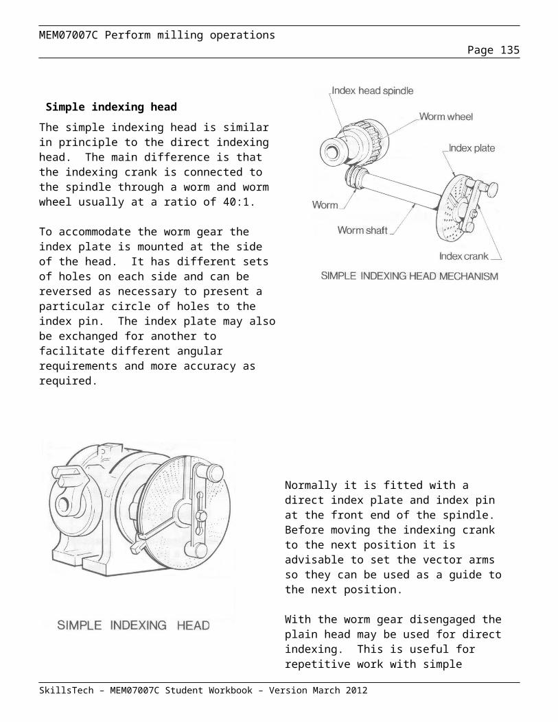
MEM07007C Perform milling operationsPage 135
Set of bore gauges
SURFACE COMPARATOR OR SCRATCH GAUGE
Surface comparators allow the estimation of surface roughness, by both touch and sight.In summary, this test method requires that the appropriate comparator is selected and compared with the surface by sight - with or without magnification, or touch. The closest match to the actual surface indicates the surface roughness.Comparisons should be made at an agreed series of locations, which characterize the surface. N6, N7, N8, N9, N10 and N11 equivalent to 0.8, 1.6, 3.2, 6.3, 12.5 and 25µm (microns) roughness averages respectively. (See page 86 on surface texture)
SMALL HOLE GAUGES
Small hole gauges are designed to measure holes ranging in size from 3 mm to 12 mm. A small hole gauge is similar to a telescoping gauge in construction and use, except that its contact surfaces consist of a small split ball mounted on the end of a handle instead of cross arms. The ball contact halves are flattened to permit there use in shallow holes and the recesses. The halves of the ball are expanded until they contact the sides of the hole by turning the knurled knob at the end of the handle. When the correct feel is obtained read the instrument with a micrometer.
SkillsTech – MEM07007C Student Workbook – Version March 2012
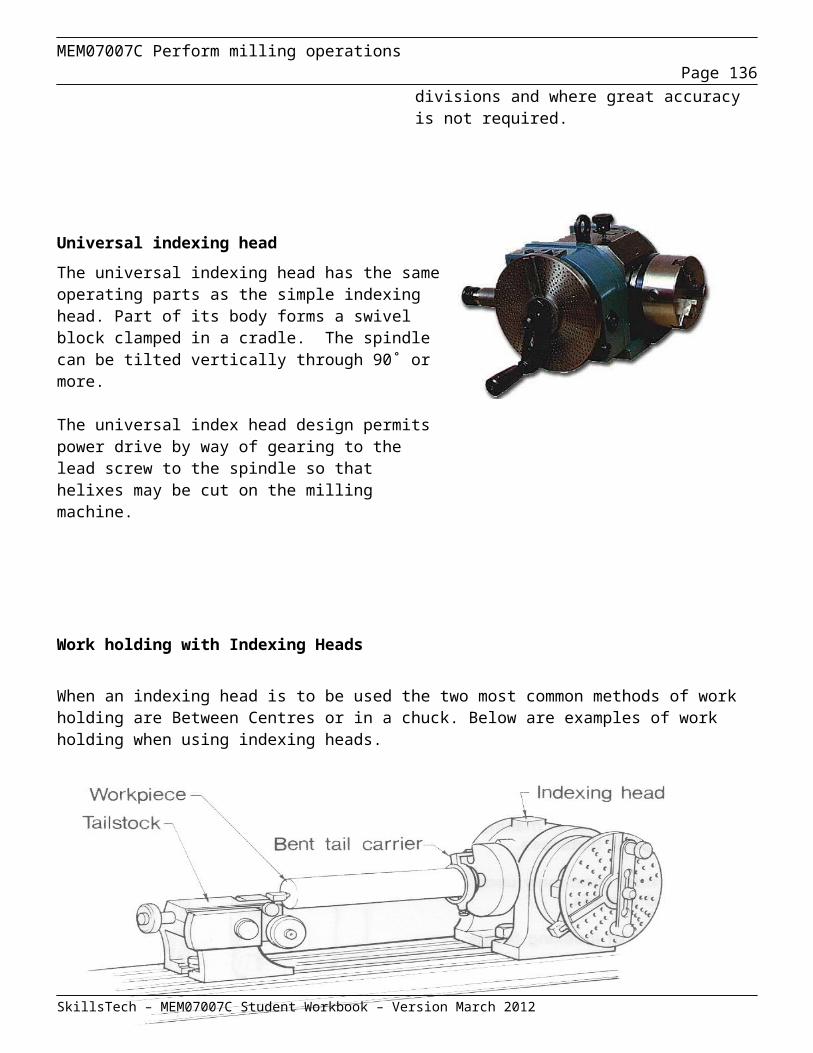
MEM07007C Perform milling operationsPage 136
Recording size conformance
Every time you deal with a specification or job instruction, you're dealing with a part of the quality system. The specification has been created by someone in the company who has found out from the customer exactly what he or she wants in the product.The specification also sets the minimum conditions which must be met for a product or service to meet its “fitness for purpose”.
The table below is a sample of a Quality Inspection Sheet that would be similar to those used in enterprises where a quality system was being used to recode conformance to specifications.
Student Exercise
After manufacture of the Overarm, students are to complete the table below and request quality verification by the teacher.
Component - Overarm Dwg. Size Dwg.
ToleranceActual Size
Width of end slot 12.00 to 12.02 0.02
Depth of end slot 17.50 to 17.55 0.05
Diameter of Pinion bore 30.00 to 30.02 0.02
Depth of Pinion bore 25.50 to 25.60 0.1
Length to Pinion bore centreline 27.50 to 27.58 0.08
Quality Verified By: TEACHER:________________________________
SkillsTech – MEM07007C Student Workbook – Version March 2012
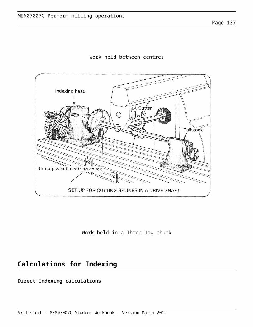
MEM07007C Perform milling operationsPage 137
Review Questions – Check components for conformance
Question 1
Name four (4) instruments used to check features on a job to determine if the job meets the required specification.
1) ___________________________________________________________
2) ____________________________________________________________
3) ____________________________________________________________
4) ____________________________________________________________
Question 2
Describe how you should check a thread conforms to all its specifications.
_____________________________________________________________________
_____________________________________________________________________
_____________________________________________________________________
_____________________________________________________________________
_____________________________________________________________________
Question 3
State two (2) methods of checking internal threads to specifications.
1) __________________________________________________________
2) ___________________________________________________________
SkillsTech – MEM07007C Student Workbook – Version March 2012

MEM07007C Perform milling operationsPage 138
Question 4
Describe the possible faults from continuous usage that may occur with GO/NOGO gauges that a tradesperson needs to check to ensure accuracy is maintained.
_____________________________________________________________________________________
_____________________________________________________________________________________
_____________________________________________________________________________________
Question 5
Describe the correct care of precision gauges.
______________________________________________________________________________________
______________________________________________________________________________________
______________________________________________________________________________________
Question 6
Describe the correct procedure for using a GO/NOGO gauge.
_____________________________________________________________________________________
_____________________________________________________________________________________
_____________________________________________________________________________________
Question 7
How is the GO end of a GO/NOGO plug gauge identified?
____________________________________________________________________________________
SkillsTech – MEM07007C Student Workbook – Version March 2012

MEM07007C Perform milling operationsPage 139
Section 7 – Drawing appendix
Arbor Press - Sheet 1
SkillsTech – MEM07007C Student Workbook – Version March 2012
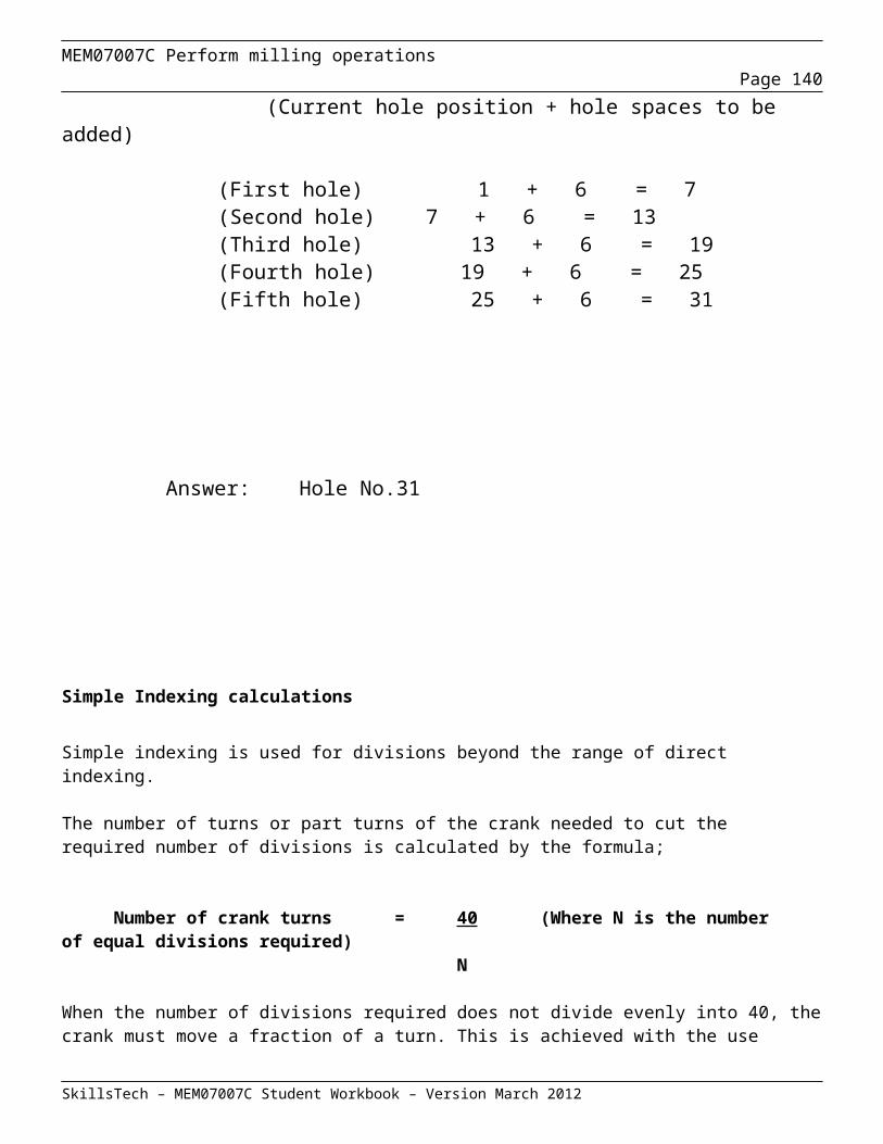
MEM07007C Perform milling operationsPage 140
Arbor Press – Sheet 2
SkillsTech – MEM07007C Student Workbook – Version March 2012

MEM07007C Perform milling operationsPage 141
Arbor Press – Sheet 3
SkillsTech – MEM07007C Student Workbook – Version March 2012
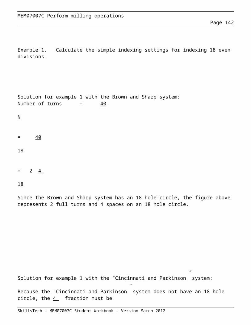
MEM07007C Perform milling operationsPage 142
SkillsTech – MEM07007C Student Workbook – Version March 2012
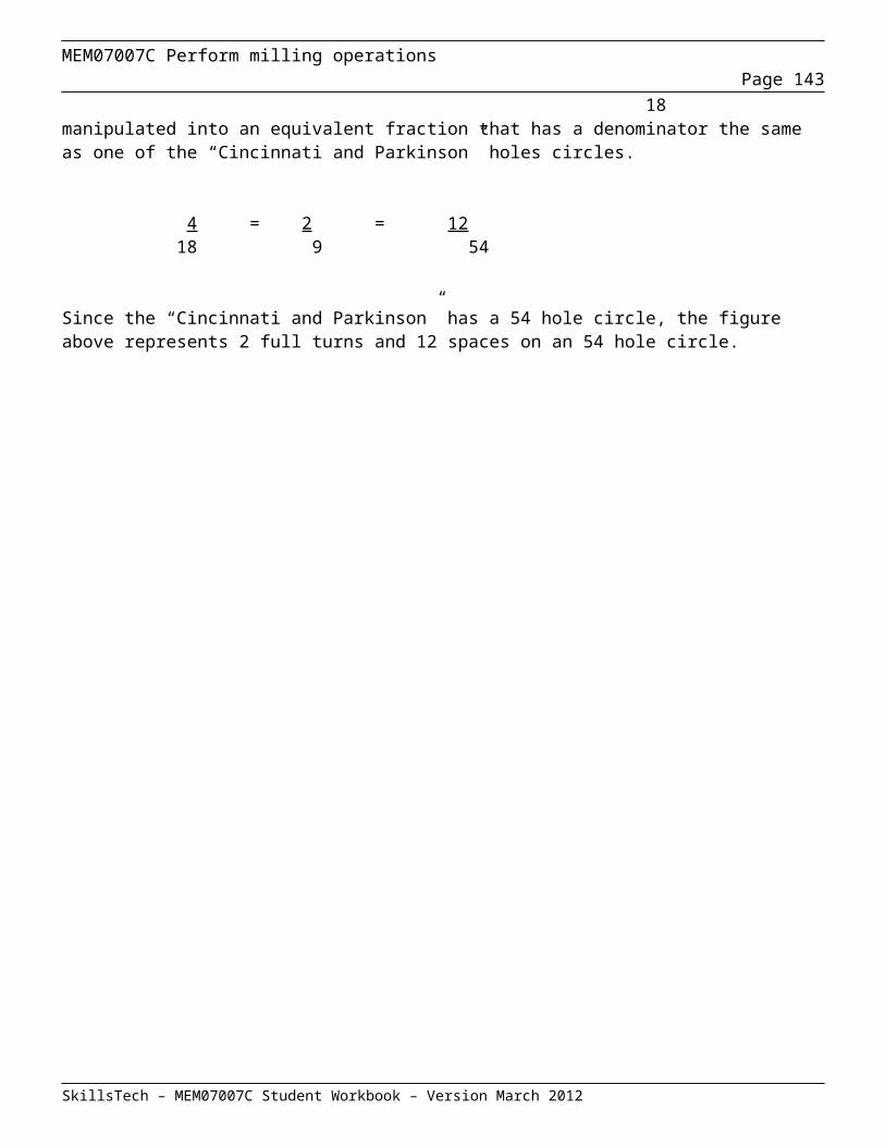
MEM07007C Perform milling operationsPage 143
Arbor Press – Sheet 4
SkillsTech – MEM07007C Student Workbook – Version March 2012
17.5017.48
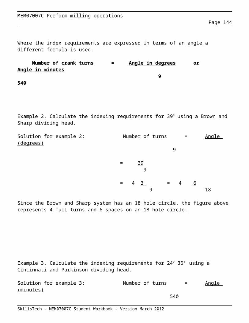
MEM07007C Perform milling operationsPage 144
Arbor Press – Sheet 5
SkillsTech – MEM07007C Student Workbook – Version March 2012
40
40
40
40
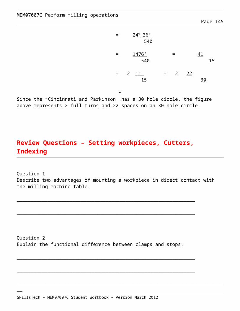
MEM07007C Perform milling operationsPage 145
Hazard Identification, Risk Assessment And Control Procedure 1. Purpose
1.1 To ensure that there is a formal process for hazard identification, risk assessment and control to effectively manage hazards that may occur within the workplaces.
2. Preamble
2.1 Why make the workplace safer? There are three main reasons:
(i) Out of concern for the health and safety of staff, employees, students, and visitors.
(ii) It makes good business sense and is cost effective.
(iii) So that the correct duty of care to employees, customers, contractors, students and visitors can be undertaken, and so health and safety legal requirements can be met.
2.2 Workplace hazard identification, assessment and control are an on-going process. It should be undertaken at various times, including:
(i) If it has not been done before.
(ii) When a hazard has been identified.
(iii) When a change to the workplace occurs.
(iv) After an incident, accident or workplace illness.
(v) At regularly scheduled times appropriate to the workplace.
2.3 The following procedure for risk assessment (involving hazard identification, risk assessment and control) is a practical guide for helping make all workplaces safe for staff, employees, students, contractors, and visitors. It will help both management and employees, through consultation, to comply with the health and safety regulations set by the Work Cover regulatory authority. These regulations require employers to identify, assess, fix and record all hazards and risks in their workplace.
2.4 The procedure will assist in:
(i) Finding hazards in our workplaces.
(ii) Assessing the risks that may result because of the hazards.
SkillsTech – MEM07007C Student Workbook – Version March 2012

MEM07007C Perform milling operationsPage 146
(iii) Deciding on control measures to prevent or minimise the level of the risks.
(iv) Fixing the problem using control measures.
(v) Monitoring and reviewing the effectiveness of the measures.
Definitions 3.1 Hazard: Anything (e.g. condition, situation, practice, behaviour) that has the potential to cause harm, including injury, disease, death, environmental or property and equipment damage.
3.2 Hazard Identification: This is the process of examining each work area and work task for the purpose of identifying all the hazards which are “inherent in the job”. Work areas include but are not limited to machine workshops, laboratories, office areas, agricultural and horticultural environments, stores and transport, maintenance and grounds, reprographics, and lecture theatres and teaching spaces. Tasks can include (but may not be limited to) using screen based equipment, audio and visual equipment, industrial equipment, hazardous substances and/or teaching/dealing with people, driving a vehicle, dealing with emergency situations, construction.
3.3 Risk: The likelihood or probability that a hazardous event (with a given outcome or consequence) will occur.
3.4 Risk Assessment: Can be defined as the process of assessing the risks associated with each of the hazards identified so that appropriate control measures can be implemented based on the probability, ie. Likelihood that harm, injury or ill health may occur and how severe the consequences of exposure might be.
3.5 Risk Control: This is the process of identifying and implementing the most cost effective risk control measures having regard to the Hierarchy of Control Principle, legislative provisions, Australian Standards and other relevant information.
3.6 Monitoring and Review: This involves ongoing monitoring of the hazards identified, risk assessment and risk control processes and reviewing them to make sure they are working effectively.
4. Aim 4.1 We are committed to providing and implementing a procedure to cover both systematic and incidental identification, assessment and control of all workplace hazards so that it meets its statutory occupational health and safety obligations.
OH&S legislation requires that once a hazard has been identified, an employer is required, in consultation with employees (or their representative),
SkillsTech – MEM07007C Student Workbook – Version March 2012

MEM07007C Perform milling operationsPage 147
to determine how likely it is that someone could be harmed by the hazard and what the consequence of the resulting injury or illness could be. If the problem is obvious and the likelihood of injury and the seriousness of injury is thought to be high, act immediately to control the risk by using an interim short-term measure. Then do the research required to fully assess the risk and decide on solutions.
The process of assessing the risk is undertaken by reviewing any available information about the hazard (e.g. a law, regulation, Australian Standard, Industry Code of Practice or guidance material about the hazard) and by using your personal work experience about what sort of accident or illness the hazard could create and how likely this would be to happen. When determining how likely it is that a person could be exposed to a hazard or hazardous event, consideration needs to be given to these “exposure factors”:
The process is as follows:
(i) Identified hazards are placed on the Hazard Summary Sheet.
(ii) The likelihood of a person being exposed to the hazard and that hazard leading to an accident or illness is determined by giving consideration to the “exposure factors” listed above.
SkillsTech – MEM07007C Student Workbook – Version March 2012

MEM07007C Perform milling operationsPage 148
Risk Assessment Table
Very LikelyCould happen
any time
LikelyCould
happen sometime
UnlikelyCould
happen but very rarely
Very unlikelyCould
happen but probably never will
Fatality or permanent disability, or property ,or environmental damage over $50000
1 1 2 3!!! Long term illness or serious injury, or property, or environmental damage between $5,000 and $50,000
1 2 3 4!! Medical attention and several days off work, or property, or environmental damage between $500 and $5,000
2 3 4 5! First aid needed, or property, or environmental damage up to $500 3 4 5 6
SkillsTech – MEM07007C Student Workbook – Version March 2012
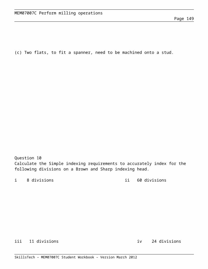
MEM07007C Perform milling operationsPage 149
SkillsTech – MEM07007C Student Workbook – Version March 2012

MEM07007C Perform milling operationsPage 150
(iii) A Risk Assessment Table (see table) is then used to categorise the likelihood and the severity or consequences of each hazard and to give it a “risk rating”.
(iv) Once a risk rating is determined, each hazard is then to be given an order of priority on the Hazard Summary Sheet. Using the Hazard Summary Sheet we can easily see the priority of corrective action for all the hazards listed on the sheet. These priorities for risk ratings are listed as follows:
i. 1 & 2: Top Priority – Isolate the hazard immediately. Must fix the cause(s) now.
ii. 3 & 4: Medium Priority – Isolate the hazard as soon as practicable. Must fix the cause(s) within 1 month. Regularly monitor the cause(s) and hazard until rectified.
iii. 5 & 6: Low Priority – Must fix the cause(s) when time and resources permit, but within 3 months. Regularly monitor the cause(s) and hazard until rectified.
6.4 Step 3 & 4: Decide On the Change Required and Make the Change
6.4.1 Having identified the hazards in your workplace and assessed their risks, they must be removed or fixed before people are hurt, become ill or there is damage to plant, property or the environment.
6.4.2 All hazards that have been assessed should be dealt with in order of priority in one or more of the following ways:
(i) Eliminate the hazard - remove it from the workplace.
(ii) Substitute the hazard - substitute a substance, method or material to reduce the risk or the hazard.
(iii) Isolate or enclose the hazard - separate the hazard from the workplace, eg:
A. Chemical store room, or laboratory kept locked except to an authorised person.
B. Lock out procedures on faulty equipment.
C. Appropriate guarding for machinery.
(iv) Use engineering solutions – modify existing machinery or plant or purchase different machinery or plant.
SkillsTech – MEM07007C Student Workbook – Version March 2012

MEM07007C Perform milling operationsPage 151
(v) Administrative Procedures - develop work methods to reduce the conditions of risk, eg:
A. Written Safe Operating Procedures
B. Job rotation to restrict hours worked on difficult jobs.
C. Staff trained in the correct operating procedures.
(vi) Use Personal Protective Equipment (PPE) and training in its use - this should only be used as a last resort to deal with the hazard, where the hazard cannot be removed or reduced by any other means, eg:
A. Handling of chemicals – gloves, safety glasses, aprons.
B. Protecting eyes from flying particles.
C. Protecting feet – safety boots.
(vii) Finding solutions to hazards may involve:
A. Assessment of the hazard by other UWS stakeholders e.g. Capital Works & Facilities, IT, or other Departments if the solution is outside your responsibility.
B. Giving consideration to make procedural changes both in-house and/or with other UWS stakeholders.
C. Making changes to work practice or behaviour.
6.5 Step 5: Monitor and Review 6.5.1 Hazard identification, risk assessment and control is an on-going process. Therefore, regularly review the effectiveness of your hazard assessment and control measures. Make sure that you undertake a hazard and risk assessment when there is a change to the workplace including when work systems, tools, machinery or equipment change. Provide additional supervision when new employees with reduced skill levels or knowledge are introduced to the workplace.
Summary Of Hazard And Risk Assessment Procedure Step 1: Describe the activity or task undertaken. Identify and list the hazard(s).
What is the hazardous event that could take place? TIP: Be aware that more than one event may take place.
• Check if an incident has occurred in the past.
SkillsTech – MEM07007C Student Workbook – Version March 2012
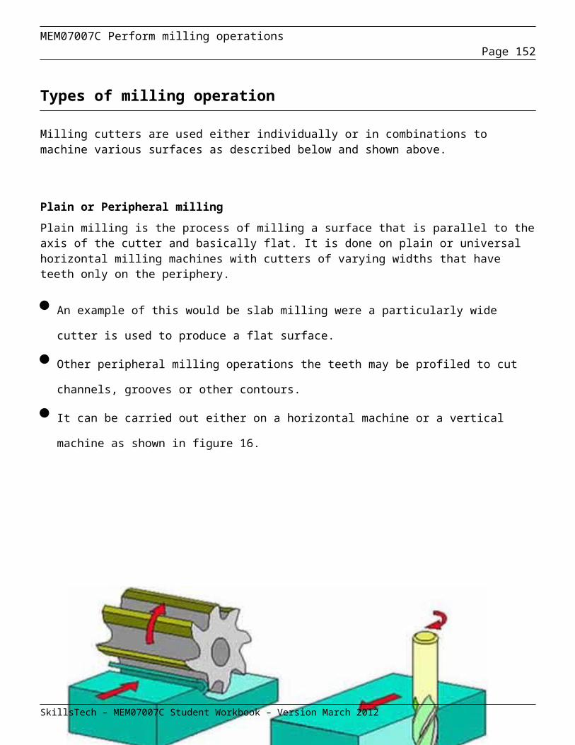
MEM07007C Perform milling operationsPage 152
• Talk with those who do the job.
• Think about what could happen if something went wrong.
Step 2: Analyse the likelihood of exposure to the hazard by identifying:
• Any other risk factors that would increase the likelihood of exposure. e.g. lack of training, no safe work procedure.
• How often is the person exposed to the hazard (frequency)?
• For how long is the person exposed to the hazard (duration)?
• How many people are exposed to the hazard?
• What is the likely dose to which the person will be exposed?
• Any legislative or recommended exposure levels required by statutory authorities.
Step 3: Having gathered information in steps 1 & 2, now determine how likely or probable it is, that the hazardous event will take place and the person will be exposed to the hazard.
• Very likely could happen any time.
• Likely could happen sometime.
• Unlikely could happen but very rarely.
• Very unlikely could happen, but probably never will.
Step 4: Determine the resulting consequence/impact, were the hazardous event to occur. Could cause:
• Fatality or permanent disability, or property, or environmental damage over $50,000. OR
• Long term illness or serious injury, or property, or environmental damage between $5,000 and $50,000. OR
• Medical attention and several days off work, or property, or environmental damage between $500 and $5,000. OR
• First aid required, or property, or environmental damage up to $500
Step 5: Link the likelihood rating to the consequence rating to give a risk priority of either:
SkillsTech – MEM07007C Student Workbook – Version March 2012
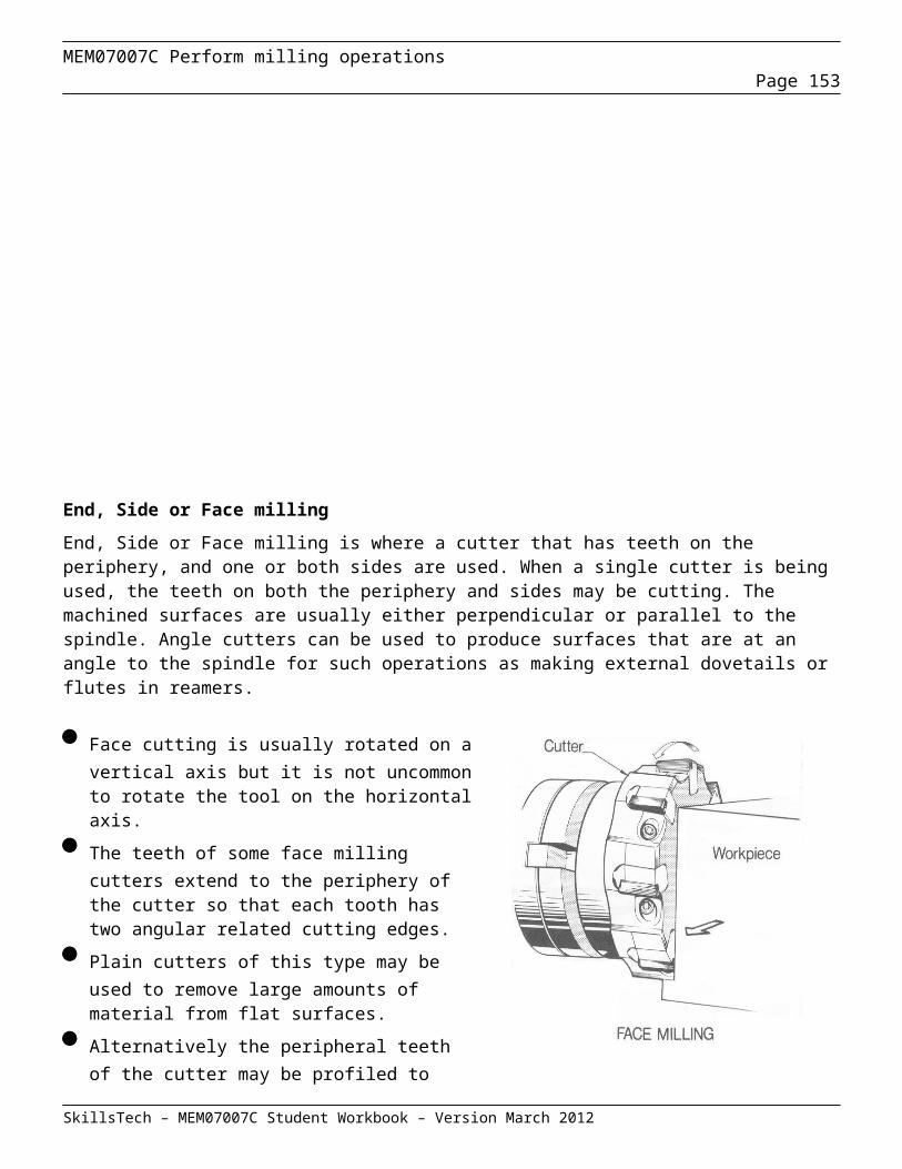
MEM07007C Perform milling operationsPage 153
• 1 & 2: Top Priority – Isolate the hazard immediately. Must fix the cause(s) now.
• 3 & 4: Medium Priority – Isolate the hazard as soon as practicable. Must fix the cause(s) within 1 month. Regularly monitor the cause(s) and hazard until rectified.
• 5 & 6: Low Priority – Must fix the cause(s) when time and resources permit, but within 3 months. Regularly monitor the cause(s) and hazard until rectified.
Step 6: Identify and list short and long-term solutions to either eliminate the hazard or reduce the risk. Determine by how much the risk would reduce if your solutions were implemented. Reassess the risk in relation to your proposed solutions, by repeating steps 2 to 5.
8. Risk Assessment Worksheet 8.1 Some hazard identification and risk assessment processes are quite complex. Attachment 2 to this document contains a copy of a “Hazard Identification Risk Assessment & Control Worksheet”. The completion of this worksheet involves:
(i) Identifying the major hazards related to a risk assessment.
(ii) Assessing the risk of each hazard, and
(iii) Developing any control actions required.
SkillsTech – MEM07007C Student Workbook – Version March 2012
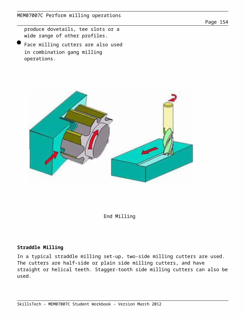
MEM07007C Perform milling operationsPage 154
Risk Assessment Activity: Risk assessment No.Completed by: Date of assessment:Identified Risk Refer to Risk calculatorRisk No: (list all risks associated with above activity) Likelihood Consequence Rating
12345678
Risk controls : ( list controls for each identified risk )12345678
Elimination : (most effective)Substitution:Reduction:
Engineering Controls: ( ie. Barriers, isolation, shut down etc.Administrative controls: (ie. Training, procedures etc.)Personal Protective/ Safety Equipment: (least effective)
Control Measures acted on. Student Signature: Teachers Signature:
SkillsTech – MEM07007C Student Workbook – Version March 2012