Embed Size (px)
Citation preview

IES5028-4GS series
Managed Industrial Ethernet switches
CLI user manual
Version 1.0.0, Apr. 2015
www.3onedata.com

Statem
Copyright
InfRe
Trademar
Teres
Agreemen
Aswistakin
Revision
Notes
In
ment
t Notice
formation eproduction
rks Notice
anechnology Cspective ma
nt
s the produithout notiatement, innd, either e
History
VersV
reading th
Inform
Special
IES5
in this docn and extra
nd Co.,Ltd. All anufacturers
uct versionce. Unlessnformationexpressed o
sion No. V1.0.0
his manual,
mation nece
l attention
5028-4G
cument is ract without
other trades.
n upgrades s other agrn and suggor implied.
, please pay
essary to ex
1
GS series
eserved byt permissio
is regemarks or re
or other rereement, thgestion in .
Date
2015-04-01
y attention
xplain
user ma
y Shenzhenon is prohib
gistered traegistered ma
easons, thishis documethis docum
C
to the foll
anual
n 3onedata bited.
ademarks oarks in this
s documenent only ament, with
ReasoCreating Do
owing sym
CLI us
www.3
Technolog
of Shenzhemanual bel
nt is subjectas a guide hout warran
on
ocuments
mbols,
ser manual
3onedata.com
gy Co., Ltd
en 3onedatalong to their
t to changeto use. Alnty of any
l
m
d.
a r
e l y

CLI user manual
2 www.3onedata.com
Content
CHAPTER 1 LOGIN ETHERNET SWITCH .................................................................................. 1
1.1 CONFIGURATION THROUGH CONSOLE PORT .................................................................................... 1 1.2 CONFIGURATION THROUGH TELNET ............................................................................................... 3 1.3 AGREEMENT .................................................................................................................................. 5 1.4 COMMAND LINE PORT .................................................................................................................... 5
1.4.1 View of Command Lines ................................................................................................ 5 1.4.2 Command lines Online help ................................................................................................. 8 1.4.3 Frequent Incorrect Information of Command Lines .......................................................... 9 1.4.4 History command ............................................................................................................ 9
CHAPTER 2 DEVICE SYSTEM BASED INFORMATION CONFIGURATION .................... 11
2.1 ENTER INTO THE VIEW OF DEVICE INFORMATION .......................................................................... 11 2.2 DISPLAY DEVICE INFORMATION .................................................................................................... 11 2.3 CONFIGURATION INFORMATION ................................................................................................... 12 2.4 DELETE DEVICE INFORMATION ..................................................................................................... 12
CHAPTER 3 PORT CONFIGURATION ....................................................................................... 14
3.1 PORT INFORMATION ..................................................................................................................... 14 3.2 DISPLAY PORT CONFIGURATION INFORMATION ............................................................................. 14 3.3 PORT CONFIGURATION ................................................................................................................. 14 3.4 TO ENABLE OR DISABLE THE PORT ............................................................................................... 14 3.5 CONFIGURE THE PORT SPEED AND DUPLEX MODE ......................................................................... 15 3.6 CONFIGURE THE PORT FLOW CONTROL ......................................................................................... 15
CHAPTER 4 BANDWIDTH MANAGEMENT ............................................................................. 16
4.1 ENTER RATE MANAGEMENT VIEW ................................................................................................ 16 4.2 EGRESS BANDWIDTH CONFIGURATION ......................................................................................... 16 4.3 INGRESS BANDWIDTH CONFIGURATION ........................................................................................ 17 4.4 DISPLAYS THE BANDWIDTH CONFIGURATION INFORMATION ........................................................ 17
CHAPTER 5 BROADCAST STORM SET ..................................................................................... 18
5.1 SET THE VIEW INTO THE BROADCAST STORM ................................................................................ 18 5.2 SHOW BROADCAST STORM SET..................................................................................................... 18 5.3 CLOSE BROADCAST STORM INHIBITION ........................................................................................ 18 5.4 SET BROADCAST STORM INHIBITION ............................................................................................ 18
CHAPTER 6 VLAN ........................................................................................................................... 20
6.1 INTRODUCTION TO VLAN ........................................................................................................... 20 6.2 THE CONTENTS OF VLAN CONFIGURATION ................................................................................. 20 6.3 VLAN INFORMATION VIEW ........................................................................................................... 20 6.4 ENTER THE PORT CONFIGURATION VIEW BASED ON VLAN ........................................................... 21 6.5 ENTER CONFIGURATION VIEW BASED ON 802.1QVLAN ............................................................... 21

CLI user manual
3 www.3onedata.com
CHAPTER 7 MULTICAST FILTERING VIEW .......................................................................... 23
7.1 ENTER THE MULTICAST FILTERING VIEW ..................................................................................... 23 7.2 CONFIGURE MULTICAST FILTERING TYPE ..................................................................................... 23 7.3 IGMP LISTEN AND CHECK ..................................................................................................... 23 7.4 DISPLAY IGMP INFORMATION ............................................................................................. 24 7.5 THE GMRP CONFIGURATION ................................................................................................ 24
CHAPTER 8 QOS.............................................................................................................................. 25
8.1 ENTER THE MULTICAST FILTERING VIEW ..................................................................................... 25 8.2 ENABLE DSCP / COS ............................................................................................................... 25 8.3 QOS QUEUE CONFIGURATION ............................................................................................... 25 8.4 THE VALUE OF DSCP/TOS MAPPING .................................................................................... 26 8.5 THE DEFAULT PORT PRIORITY ALLOCATION ...................................................................... 26 8.6 QOS CONFIGURATION INFORMATION ................................................................................... 26
CHAPTER 9 RING CONFIGURATION ........................................................................................ 27
9.1 ENTER THE RING NETWORK CONFIGURATION VIEW ...................................................................... 27 9.2 RING NETWORK STATE INFORMATION VIEW ...................................................................... 27 9.3 TO ENABLE OR DISABLE THE RING ....................................................................................... 27 9.4 THE RING3 CONFIGURATION ................................................................................................ 28 9.5 RING NETWORK CONFIGURATION INFORMATION ............................................................... 29 9.6 THE RSTP CONFIGURATION .................................................................................................. 29 9.7 DISPLAY THE CURRENT STATE OF THE RSTP INFORMATION ........................................... 30
CHAPTER 10 TRUNK CONFIGURATION .................................................................................. 31
10.1 ENTER THE PORT TRUNK VIEW .................................................................................................. 31 10.2 PORT TRUNK CONFIGURATION / DELETE .......................................................................... 31 10.3 DISPLAY PORT TRUNK CONFIGURATION INFORMATION ................................................. 31
CHAPTER 11 MAC PORT LOCK ................................................................................................. 32
11.1 ENTER THE MAC PORT LOCK VIEW ........................................................................................... 32 11.2 MAC PORT LOCKING INFORMATION DISPLAY ................................................................. 32 11.3 ADD OR REMOVE MAC PORT LOCKING INFORMATION .................................................. 32
CHAPTER 12 EMAIL ALARM CONFIGURATION .................................................................. 33
12.1 ENTER THE EMAIL ALARM VIEW ................................................................................................ 33 12.2 DISPLAYS THE EMAIL ALARM INFORMATION ................................................................... 33 12.3 CONFIGURE EMAIL ALARM INFORMATION ....................................................................... 33
CHAPTER 13 ALARM CONFIGURATION ................................................................................. 34
13.1 ENTER THE ALARM INFORMATION VIEW .................................................................................... 34 13.2 ALARM CONFIGURATION / DELETE .................................................................................... 34 13.3 DISPLAY THE ALARM INFORMATION ........................................................................................... 34
CHAPTER 14 PORT MIRRORING ............................................................................................... 36
14.1 ENTER THE PORT MIRRORING VIEW ............................................................................................ 36

CLI user manual
4 www.3onedata.com
14.2 PORT MIRRORING CONFIGURATION / DELETE .............................................................................. 36 14.3 DISPLAY PORT MIRRORING INFORMATION .................................................................................. 36
CHAPTER 15 TIME CONFIGURATION ..................................................................................... 37
15.1 IN VIEW OF THE TIME CONFIGURATION ...................................................................................... 37 15.2 THE ALLOCATION OF TIME ALLOCATION VIEW ............................................................................ 37
CHAPTER 16 STATIC MULTICAST CONFIGURATION ........................................................ 38
16.1 IN THE STATIC MULTICAST ADDRESS FILTER CONFIGURATION VIEW ............................................ 38 16.2 ADD / REMOVE STATIC MULTICAST ADDRESS .............................................................................. 38 16.3 STATIC MULTICAST ADDRESS ALLOCATION ................................................................................. 38
CHAPTER 17 THE SNMP CONFIGURATION ........................................................................... 39
17.1 CONFIGURE THE VIEW INTO THE SNMP ..................................................................................... 39 17.2 ENABLE THE SNMP INFORMATION ............................................................................................ 39 17.3 THE SNMP CONFIGURATION VIEW ............................................................................................. 39
CHAPTER 18 PORT STATISTICS ................................................................................................ 40
18.1 ENTER THE PORT STATISTICAL CONFIGURATION VIEW ................................................................ 40 18.2 PORT STATISTICS CONFIGURATION VIEW .................................................................................... 40
CHAPTER 19 SYSTEM MANAGEMENT .................................................................................... 41
19.1 ENTER THE SYSTEM MANAGEMENT CONFIGURATION VIEW ........................................................ 41 19.2 SYSTEM TIMEOUT ...................................................................................................................... 41 19.3 IP ADDRESS AND DEFAULT GATEWAY SETTING ............................................................................ 41 19.4 USER NAME, PASSWORD SETTINGS ............................................................................................. 42 19.5 DISPLAY DEVICE IP, SUBNET MASK, DEFAULT GATEWAY ............................................................. 42 19.6 RESTORE FACTORY SETTINGS ..................................................................................................... 43 19.7 UPLOAD, DOWNLOAD THE CONFIGURATION FILE........................................................................ 43 19.8 THE SYSTEM UPGRADE ............................................................................................................... 44

CLI user manual
1 www.3onedata.com
Chapter 1 Login Ethernet Switch
1.1 Configuration through console port
1. Connection switches to configure terminal
As shown in Figure 1.1.1, the establishment of the local configuration environment, only the computer serial cable and connected to the Console port of the Ethernet switch.
(Figure 1.1.1)
This cable is used for connecting the IES5028-4GS series switch Console port and the external monitoring terminal equipment. One end is RJ45 eight core plug, the other end is the 9 hole plug (DB9). Console RJ45 IES5028-4GS series switch socket head, the cable inner connecting line diagram as shown below.
(Figure 1.1.2)
2. Configure terminal parameters
1) Turn the computer, on the Windows interface, click "Start/All Programs/Accessories/communication", run a terminal emulation program to create a new connection. The RS-232 port is connected to the computer. To take Hyper Terminal in Windows XP for example, as shown in Figure 1.1.3, type in a new name of the connection in a text box named "name", then click "OK" button.

2) Choose c
to the chos
“OK”. As s
3) Set seria
of serial po
Control”
connecting
en serial po
shown in Fig
al port param
ort is 115200
is None. Cl
serial port.
ort is consis
gure 1.1.4.
meters. As s
0bit/s, “D
lick “OK”
Choose con
stent with t
(F
shown in Fig
Data bits”
” button to
2
(Figure 1.1.3
nnecting ser
he port con
Figure 1.1.4
gure 1.1.5,
is 8, “par
o enter to
)
rial port und
nnected with
4)
set the “Bi
rity” is No
“Hyper Ter
der “Connec
h the config
ts per secon
one, “Sto
rminal” W
CLI us
www.3
ct using”(p
guration cab
nd” in the “
op Bits” is
Window.
ser manual
3onedata.com
pay attention
ble),Click
“Properties”
s 1, “Flow
l
m
n
k
”
w

4) Hyper te
the attribute
click < OK
5) For IES
self-test inf
<user name
switch syst
chapters of
As the netw
second" mu
1.2 Configu
Terminal dfollows: 1. The IP asystem man2. If PC an
erminal attri
es settings w
K > button to
5028-4GS
formation,
e> comman
tem mode
f the content
work pipeline c
ust choose 1152
uration thr
device use
address of IEnagement vind IES5028
ibute. In the
window. Se
o return to th
series switc
after the pr
nd prompt,
can be con
ts of the boo
connection than
200, otherwise
rough Telne
telnet conn
ES5028-4Giew); -4GS in the
e Hyper Ter
elect the ter
he hyper ter
ch power, p
rompt the u
this time t
nfigured, th
ok in.
n COM1, in ste
cannot be displ
et
nect to IES
GS series can
e same loca
3
(Figure 1.1.5
rminal wind
rminal simu
rminal wind
power after
user to type
to enter the
he specific
ep two must ch
layed.
S5028-4GS
n get it by s
al area netw
)
dow select [
ulation of ty
dow.
r the hyper
e the carria
e correct u
configurat
hoose the corre
series thro
search or m
work, the IP
document /
ype VT100
terminal d
age return, u
sername an
tion comma
sponding COM
ugh PC, th
modify (Use
P address m
CLI us
www.3
/ property /
or automati
display Ethe
until the em
nd password
ands refer
M port. Step thr
he requirem
IP comman
must in a sam
ser manual
3onedata.com
setting] into
ic detection
ernet switch
mergence o
d, enter the
to the later
ree "bits per
ments are as
nd under the
me network
l
m
o
n,
h
f
e
r
s
e
k

CLI user manual
4 www.3onedata.com
segment, otherwise, PC and IES5028-4GS must cross-router. If satisfied these two requirements, can use telnet access to IES5028-4GS series, and then configure the IES5028-4GS. 1)Establish configuration environment, just connect PC’s Ethernet port connect to IES5028-4GS’s
Ethernet port through Local area network.
(Figure 1.2.1)
2)Run the Telnet program on the PC, need to input“Telnet+ Space+ IES5028-4GS’s IP address” for checking, Figure 1.2.2 as follows:
(Figure 1.2.2)
3)Hit “Enter”, checkout successful and till PC show“Please input hostname and password”, ask user to input user name and password, default is admin, figure 1.2.3 as follows:
(Figure 1.2.3)
4)Use command to configure IES5028-4GS series and check the running statues, if need help, please input“?” at any time. Specific configuration command, please reference“IES5028-4GS

CLI user manual
5 www.3onedata.com
series CLI user manual”.
1.3 Agreement
1. Command line format agreement table 1.3.1 as follow Table 1.3.1
Format Description
Bold Key words of the command show by bold type.
italic Parameter of the command show italic type.
[ ] It shows part in “[]”is optical when command configuration is need.
{ x | y | ... } It shows to pick up one from two or more items.
[ x | y | ... ] It shows to pick up one or no one from two or more items.
{ x | y | ... } It shows to pick up one at least, all at most from two or more items.
2. Format agreement of figure interface Table 1.3.2 as follows:
Table 1.3.2
Format Description
< > “< >” shows press name, like ”click<OK>”
[ ] “[ ]” shows windows name, menu name and data list. like “eject [create user]window”
/ Multilevel is separated by “/”. Like [file/create/folder] means[create] a [folder] under the
menu of [file]
1.4 Command line port
IES5028-4GS series provide command lines port and its configuration for user’s easy configuration and management. Command lines port includes the following features:
1. Local configuration through Console port; 2. Supports history command saving which means it can save 10 pieces. History commands can
be selected by up and down key.
3. User can type in “help” or ”?” to get some help;
4. Supports intelligent complement with Tab when commands input; 5. Command interpreter take the method of partial matching. User can type in conflict-free key
words, such as config command, only need to type in conf.
1.4.1 View of Command Lines
IES5028-4GS series’ view of command lines aim at configuration of different functions. First
of all, IES5028-4GS series establish connection, then confirmation of user name and password
finished, after enter the correct user name and password, enter “help or ?” in “switch”, enter into
system view, Under the view of system, corresponding view appears after typing indifferent

CLI user manual
6 www.3onedata.com
command, figure 1.4.1 as follows:
(Figure 1.4.1)
Table 1.4.1 system view command list
View Function DOS Prompt Enter Quit
System View Switch# Quit and return to
user login
Information Show or modify device information, like software version, IP address, etc.
Switch (information)#
Information
Exit and
return to
the view
of system
Port Settings Show or modify the port information, such as: duplex mode, port enable
Switch (Port)# Port
Bandwidth
Management
Show or modify the bandwidth information, such as the inlet and outlet bandwidth settings etc.
Switch
(Bandwidth)# Bandwidth
Storm Suppression The rate and type of information to view or modify the broadcast storm
Switch (storm)# Storm

CLI user manual
7 www.3onedata.com
Dynamic Multicast
View filter information or modify the GMRP enable and port information and IGMP filtering or queries enable etc.
Switch
(MultiFilter)# MultiFilter
Static Multicast
View or modify the static multicast address, such as adding a static multicast address
Switch
(Multicast)# Multicast
VLAN
View or modify the Vlan information, such as the addition of Vlan, PVID, port type etc.
Switch (Vlan)# Vlan
QoS View or modify the Qos, Tos value, such as Qos, Tos etc.
Switch (QoS)# QoS
Rapid Ring
View or modify information such as the net ring, ring ID, ring port, RSTP information etc. View or modify the RSTP information
Switch (Ring)# Ring
Port Trunking View or modify the port trunk information, such as the trunk port
Switch (Trunk)# Trunk
MAC port lock View or modify the static unicast MAC address and port
Switch (Access)# Access
SNMP
Configuration SNMP enable configuration Switch(Snmp)# Snmp
Email Warning
View or modify the message alarm information, such as mail server address, password, etc.
Switch (Email)# Email
Relay Warning View or modify the alarm information, such as power alarm, and port alarm.
Switch (Alarm)# Alarm
Port Statistics Port to receive the frame and the total amount of data statistics
Switch(Statistics)
# Statistics
Diagnosis View or modify the mirror port information
Switch (mirror)# Mirror

CLI user manual
8 www.3onedata.com
SNTP View or modify time configuration
Switch (Time)# Time
Basic Settings
View or modify the settings information, such as the IP address, subnet mask, default gateway, the user password
Switch
(manage)# Manage
1.4.2 Command lines Online help
Command lines port provides the following online help:
Total help;
Partial help;
1. Total help 1)Type in <?> to get all commands and their description.
Example:
Switch# ?
List --List commands of current menu
Help --Help commands of current menu
Quit --Exit from CLI
Exit --Exit from current menu
Reboot --Reboot switch
Port --Enter port setting menu
Bandwidth --Enter bandwidth management menu
MultiFilter --Enter multicast filtering menu
Multicast --Enter static multicast filters menu
Vlan --Enter vlan menu
QoS --Enter QoS menu
Ring --Enter Ring menu
Trunk --Enter Trunking setting menu
Snmp -- Enter Snmp setting menu
Alarm --Enter alarm setting menu
Statistics --Enter Statistics menu
Mirror --Enter port mirror menu
Time --Ether time menu
Manage --Enter system manage menu
Information --Enter device information menu

CLI user manual
9 www.3onedata.com
2) Type in a command and “?”, between there is a space, if key word is in this location, then type
in all keywords and descriptions.
Example:
Switch (information)# show ?
mac --show device MAC Address
version --show device version
others --show device type、name、etc
2. Partial help 1)Type in a character string with <?>. It can show all commands beginning with this character string. Example: Switch# R?
Reboot --Reboot switch
Ring --Enter Ring menu
2)Type in former letters of some key word of the command, press<Tab> key. If the letters are unique, it can show the completed key word. Example: Switch# inf+<Tab> Switch# information
1.4.3 Frequent Incorrect Information of Command Lines
All commands typed by users, if it is certificated by grammar, it can run correctly, or users will be sent incorrect information. Frequent incorrect information is in table 1.4.3 as below:
Table 1.4.3 Frequent incorrect information
English incorrect information Reason
Invalid Command
Command cannot be found.
Key word cannot be found.
The type of parameter is wrong.
The parameter is beyond the border.
Incomplete Command Command is not completed.
Too many parameters Parameter is too much.
1.4.4 History command
Command lines port can provides the function similar to Dos key. It automatic save command lines that users
types in, and users can use these history commands. Detailed operating please check table 1.4.4 as follows:

CLI user manual
10 www.3onedata.com
Table 1.4.4 access history command
Operating Key Result
Visit previous history command Up <↑> If it exists earlier command, it is taken out.
Visit next history command Down <↓> If it exists later command, it is taken out.

CLI user manual
11 www.3onedata.com
CHAPTER 2 Device system based information configuration
Device information includes Device Type, Hardware Version, Device Name, Software Version, Device Description,
Device SN and Contact Way. Among them, Hardware Version and Software Version can be only read, not modified.
2.1 Enter into the view of device information
Please check the view as figure 2.1.1 Table 2.1.1
Operating Command Description
Enter into the view of device information Information Run in the view of system
2.2 Display device information
Please check the device information command as table 2.2.1 Table 2.2.1
Operating Command Description
Show system version show
version Carry our under the view of device information
Show MAC address of device show mac Carry our under the view of device information
Show Device Type, Name, etc. show others Carry our under the view of device information
Configure device model, name etc config Carry our under the view of device information
Delete device model, name etc clean Carry our under the view of device information
Example: Enter into device information view, enter the bold type command as follows and enter return key
Switch# information
Switch(information)# ?
List --List commands of current menu
Help --Help commands of current menu
Quit --Quit from CLI
Exit --Exit from current menu
Reboot --Reboot switch
Show mac --Show device MAC Address
Show version --Show device version
Show others --Show device type,name,etc
Config --Config device type,name,etc
Clean --Clean device type,name,etc /
Example: Check device name and model number etc

CLI user manual
12 www.3onedata.com
Switch (information)# show others
Device type Managed Switch
Device name Industrial Switch
Description 28PORT
Serial number
Contact way
Example: Check the MAC address
Switch(information)# show mac
Device MAC address: 00.22.6F.02.B0.83
2.3 Configuration information
Please reference user configuration device information as table 2.3.1: Table 2.3.1
Operating Command Description
Configure Device Type config –t type Type: configurable type, the length is between
1~16 characters
Configure Device Name config -n name Name: configurable name, the length is
between1~16 characters
Configure Serial Number config -m number Number: configurable number, the length is
between 1~16 characters
Configure Device Description config -p descriptionDescription: configurable description, the length
is between 1~16 characters
Configure Contact information config -c contact Contact: Configure Contact way 1-30 bytes
Example: Configure device name as AB123, enter the bold type command as follows and enter return key:
Switch(information)# config -n ABC123
[OK]
Example: Configure device serial number as 201304111, enter the bold type command as follows and enter return
key:
Switch(information)# config -m 201304111
[OK]
2.4 Delete device information
Please reference table 2.4.1

CLI user manual
13 www.3onedata.com
Table 2.4.1
Operating Command Description
Delete Device Type Clean –t Carry our under the view of device information
Delete Device Name Clean -n Carry our under the view of device information
Delete Serial Number Clean -m Carry our under the view of device information
Delete Device Description Clean -p Carry our under the view of device information
Delete Contact information Clean -c Carry our under the view of device information
Example: Delete device name, enter the bold type command as follows and enter return key:
Switch(information)# clean -n
[OK]
Example: Delete Serial Number, enter the bold type command as follows and enter return key:
Switch(information)# clean -m
[OK]
Example: Delete Contact information, enter the bold type command as follows and enter return key:
Switch(information)# clean -c
[OK]

CLI user manual
14 www.3onedata.com
Chapter 3 Port Configuration
Port information including link state (link or LOS), the port state (full or half), rate mode (automatic negotiation, 10Mbps, 100Mbps), interface type (electric or optical), flow control, port is enabled.
3.1 Port information
The Ethernet port characteristics of IES5028-4GS series switches support: 10/100Base-Tx Ethernet port can operate in half duplex, full duplex, auto negotiation mode. Support MDI/MDIX adaptive, and able to negotiate with other network devices, automatic selection of the most appropriate way of working and rate, which greatly simplifies the configuration and management system; 100Base-FX port, rate of 100Mbps, working in full duplex mode, flow control can be set. Enter the port configuration view Table 3.1.1 to enter the port configuration view:
Table 3.1.1
Operating Command Description
Enter the port configuration view port In view of the system under the
3.2 Display port configuration information Table 3.2.1 shows the command port configuration information:
Table 3.2.1
Operating Command Description
Display port state information Show state <portlist> <portlist>:1,3,5-28 or all
Display port configuration
information Show config <portlist> <portlist>:1,3,5-28 or all
Example: display port state information 3, 4 Switch (Port)# show state 3,4
port3 Speed: 10M Port status: HALF Link status: LOS Interface type: TX
port4 Speed: 10M Port status: HALF Link status: LOS Interface type: TX
3.3 Port configuration Port configuration including: 1 To enable or disable the port; 2 Configure the port speed and duplex mode; 3 The allocation of port flow control; 4 Remove the statistics information of port frame; 3.4 To enable or disable the port The user can use the following command to open or close the port. By default, the port is enabled. Table 3.3.1 to enable or disable the port:
Table 3.3.1

CLI user manual
15 www.3onedata.com
Operating Command Description
Enable port Enable <portlist> {enable|disable} <portlist>:1, 3, 5-28 or all
Example: 3, 4, 6 closed port
Switch(Port)# Enable 3,4,6 disable
[OK]
3.5 Configure the port speed and duplex mode Table 3.4.1 configure the port speed and duplex.
Table 3.4.1
Operating Command Description
Configure the
port speed and
duplex mode
Mode <portlist> {10h|10f|100h|100f|1000h|auto}
<portlist>:1,3,5-28 or all
mode:
10h, 10Mbps Half duplex
10f, 10Mbps Full duplex
100h, 100Mbps Half duplex
100f, 100Mbps Full duplex
1000h,1000 Mbps Half duplex
Auto: Automated negotiation
Example: Rate of 3, 4, 5 100Mbps full duplex port configuration Switch(Port)# Mode 3-5 100f
[OK]
3.6 Configure the port flow control Table 3.5.1 to enable or disable the port flow control:
Table 3.5.1
Operating Command Description
Enable port flow control Flow-con <portlist> enable <portlist>:1,3,5-28 or all
Disable port flow control Flow-con <portlist> disable <portlist>:1,3,5-28 or all
Example: open port 3, 4, 5 flow control Switch (Port)# flow-con 3,4,5 enable
[OK]

CLI user manual
16 www.3onedata.com
Chapter 4 Bandwidth Management
4.1 Enter rate management view
Bandwidth allocation including: 1. Entrance velocity distribution; 2. The outlet velocity distribution; 3. Check the entrance rate configuration information; 4. Check the export rate of configuration information; Table 4.1.1 in bandwidth management view:
Operating Command Description
bandwidth management Bandwidth In view of the system under
4.2 Egress bandwidth configuration By default, the egress bandwidths not limit. Table 4.2.1 Egress bandwidth configuration:
Table 4.2.1
Operating Command Description
Egress bandwidth Config egrate <portlist> < Bandwidth >
<portlist>:1,3,5-28 or all
<Bandwidth>:(64k, 128k, 256k, 512k, 1M,
2M, 3M, 4M, 5M, 6M, 7M, 8M, 9M, 10M,
20M, 30M, 40M, 50M, 60M, 70M, 80M,
90M, 100M, 200M, 300M, 400M, 500M,
600M, 700M, 800M, 900M, 1000M)
0: unlimited
Example: set the 1 port of egress bandwidth is 8M
Switch (Bandwidth) # config egrate 1 8M [OK]
Example: set port egress bandwidth limit 0 Switch (Bandwidth) # config egrate 1 0
[OK]
CLI user manual
17 www.3onedata.com
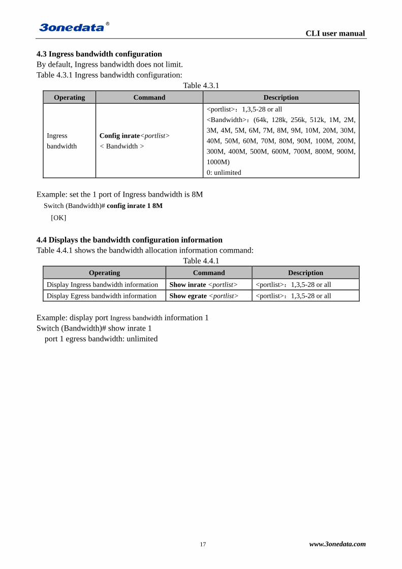
4.3 Ingress bandwidth configuration By default, Ingress bandwidth does not limit. Table 4.3.1 Ingress bandwidth configuration:
Table 4.3.1
Operating Command Description
Ingress
bandwidth
Config inrate<portlist>
< Bandwidth >
<portlist>:1,3,5-28 or all
<Bandwidth>:(64k, 128k, 256k, 512k, 1M, 2M,
3M, 4M, 5M, 6M, 7M, 8M, 9M, 10M, 20M, 30M,
40M, 50M, 60M, 70M, 80M, 90M, 100M, 200M,
300M, 400M, 500M, 600M, 700M, 800M, 900M,
1000M)
0: unlimited
Example: set the 1 port of Ingress bandwidth is 8M
Switch (Bandwidth)# config inrate 1 8M
[OK]
4.4 Displays the bandwidth configuration information Table 4.4.1 shows the bandwidth allocation information command:
Table 4.4.1
Operating Command Description
Display Ingress bandwidth information Show inrate <portlist> <portlist>:1,3,5-28 or all
Display Egress bandwidth information Show egrate <portlist> <portlist>:1,3,5-28 or all
Example: display port Ingress bandwidth information 1 Switch (Bandwidth)# show inrate 1 port 1 egress bandwidth: unlimited

CLI user manual
18 www.3onedata.com
Chapter 5 Broadcast Storm Set
5.1 Set the view into the broadcast storm The broadcast storm including: 1. Show broadcast storm set 2. Close broadcast storm inhibition 3. Set broadcast storm set Table 5.1.1 into the broadcast storm view command:
Table 5.1.1
Operating Command Description
In view of the broadcast storm Storm To perform the operation in the system.
5.2 Show broadcast storm set By default, the broadcast storm set off. Table 5.2.1 broadcast storm set configuration:
Table 5.2.1
Operating Command Description
Show broadcast storm set Show storm
5.3 Close broadcast storm inhibition Table 5.3.1 Close broadcast storm inhibition:
Table 5.3.1
Operating Command Description
Close broadcast storm inhibition
Close storm
5.4 Set broadcast storm inhibition Table 5.4.1 set broadcast storm set:
Table 5.4.1
Operating Command Description
Set broadcast storm Config {0|1} <Maximum rate>
{0|1} --Limited type
0 --Broadcast,Multicast and
flood frames
1 --Broadcast Only
<Maximum rate>
3 --3%
5 --5%
10 --10%
20 --20%
30 --30%

CLI user manual
19 www.3onedata.com
Example: the configured limit packet type is only broadcast packets, the maximum rate of 5% Switch (Storm)#Config 1 5
Maximum rate:5%
Limited type:Broadcast Only [OK]

CLI user manual
20 www.3onedata.com
Chapter 6 VLAN
6.1 Introduction to VLAN
VLAN (Virtual Local Area Network) is a virtual local area network, is a kind of device by LAN
logical rather than physical division into a network, in order to achieve the virtual group technology.
VLAN technology allows network administrators to one physical LAN logic into different
broadcast domains (or virtual LAN, VLAN), each VLAN contains a set of computer workstations
have the same needs, have the same properties and physical form on LAN. But because it is logical
rather than physical partition, so each workstation with a VLAN does not need to be placed in the
same physical space, namely the workstation does not necessarily belong to the same physical LAN
segment. Within a VLAN broadcast and unicast traffic will not be forwarded to the other VLAN,
helps to control the flow, reduce equipment investment, simplifying the management of network,
improve network security.
IES5028-4GS supports 802.1Q VLAN and port based VLAN (Port-based VLAN).
6.2 The contents of VLAN configuration
The VLAN configuration including:
1, show current VLAN type
2, VLAN Enable
3, configure the ports of Vlan information
4, the configuration of 802.1Q Vlan information
First of all to enter the Vlan configuration views.
Table 6.2.1 to enter the VLAN configuration view:
Table 6.2.1
Operating Command Description
In view of the VLAN Vlan To perform the operation in the system.
6.3 Vlan information view
Table 6.3.1 into the VLAN information view:
Operating Command Description
Enter the Vlan information view Show vlantype To perform the operation in the system.
Select the Vlan type Enable {0|1} 0: Port based on VLAN
1: 802.1Q based on VLAN
Select the port based Vlan PVLANSetting
Based on the 802.1Q Vlan QVLANSetting
Example: Vlan type: 802.1Q Vlan

CLI user manual
21 www.3onedata.com
Switch (VLAN) # enable 1
802.1Q VLAN is enable!
[OK]
Tip: This configuration will be validated after restarting
6.4 Enter the port configuration view based on Vlan
Table 6.4.1 to enter the port configuration view based on vlan:
Operating Command Description
Add Vlan Add <vid> <portlist> <vid>:VLAN ID:1-4094
<portlist>:1,3,5-28 or all
Delete Vlan Delete <vidlist> <vidlist>:1,4,5-4094 or all
To view the Vlan information Show vlan <vidlist> <vidlist>:1,4,5-4094 or all
Example: add VLAN of 2, a member of the port in 2, 3, 4, 5, 6
Switch(PortVlan)# show vlan all
VID PORT
1 1 2 3 4 5 6 7 8 9 10 11 12 13 14 15 16 17 18 19 20
2 2 3 4 5 6
6.5 Enter configuration view based on 802.1QVlan
Table 6.5.1 into the 802.1Q Vlan configuration based view:
Operating Command Description
Pvid setting config pvid <portlist> <pvid> <portlist>: 1,3,5-28 or all
<pvid>: 1,4,5-4094
Set the VLAN logo
to replace the
configuration
config replace {0|1}
0 VID is unchanged
1 Use the default VID port to replace the
logo VID
The establishment
and management of
VID
config manage <vid> 1,4,5-4094
Add Vlan Add <vid> <portlist> <typelist>
<vid> 1,4,5-4094
<portlist> 1,3,5-28 or all
<typelist> m UnModified
u UnTagged
Delete Vlan Delete <vidlist> <vidlist> 1,4,5-4094 or all
To view the VLAN
information Show vlan <vidlist> <vidlist>: 1,4,5-4094 or all
View port PVID Show pvid <portlist> <portlist>: 1,3,5-28 or all

CLI user manual
22 www.3onedata.com
Operating Command Description
To view the VLAN
logo to replace the
configuration
Show replace
View management
VID Show manage
Example: add type Vlan2 port 4 for U
Switch(VLAN)# add 2 4 u
[OK]
Tip: This configuration will be validated after restarting
Example: see VLAN 1 information
Switch (VLAN)# show vlan 1
VID 1 2 3 4 5 6 7 8 9 10 11 12 13 14 15 16···
1 U U U U U U U U U U U U U U U U ···

CLI user manual
23 www.3onedata.com
Chapter 7 Multicast filtering view
7.1 Enter the multicast filtering view
Multicast filtering configuration includes:
1. types of configuration, multicast filtering
2. listen to the IGMP
3. the IGMP query
4. the IGMP query interval configuration
5. display the IGMP sensing information
6. the configuration of GMRP enable
7. configure the GMRP port
8. display the GMRP information
Table 7.1.1 into multicast filtering view configuration commands:
Operating Command Description
In view of the configuration of
multicast filtering Multicast To perform the operation in the system.
7.2 Configure multicast filtering type
Table 7.2.1 configuration settings to configure the broadcast storm:
Operating Command Description
Configure multicast filtering type Choice{0|1} 0 IGMP Snooping
1 GMRP
Example: configure multicast filtering type: GMRP
Switch (Multicast)# Choice 1
7.3 IGMP listen and check
Table 7.3.1 configuration IGMP and IGMP query to listen:
Operating Command Description
Configure the IGMP to listen Set IGMP {enable|disable} Enable
disable
Configure the IGMP query Set query {enable|disable} Enable
disable
Configure the IGMP query interval Config query <time> Time (60-1000s)
Example: the configuration of IGMP interception enable: Enable
Switch (Multicast)#Set igmp enable
Configure the IGMP query enable: Enable

CLI user manual
24 www.3onedata.com
Switch (Multicast)#Set query enable
Configure the IGMP query interval: 60s
Switch (Multicast)#Config query 60
7.4 Display IGMP information
Table 7.4.1 shows the IGMP information:
Operating Command Description
Display IGMP information Show IGMP
7.5 The GMRP configuration
Table 6.5.1GMRP configuration:
Operating Command Description
Configure the GMRP enable Set GMRP {enable|disable} Enable
disable
Configure the GMRP port Config Query <portlist> portlist 1,3,5-28 or all
Display GMRP information Show GMRP
Example: the configuration of GMRP enable: Enable
Switch (Multicast)#Set gmrp enable
GMRP port: the port configuration
Switch (Multicast)#Config Query all

CLI user manual
25 www.3onedata.com
Chapter 8 QoS
8.1 Enter the multicast filtering view
The QoS configuration including:
1. Enable Dscp, Cos
2. Set Qos (8:4:2:1 high priority queue mechanism, strict priority)
3. The value of Cos/Dscp mapping
4. The default port priority
5. To view the QoS configuration information
Table 8.1.1 to enter the Qos configuration view:
Operating Command Description
Enter the Qos configuration view QoS To perform the operation in the system.
8.2 Enable Dscp / Cos
The user can use the following command to set the Dscp, Cos enabled.
Table 8.2.1 to DScp/Cos
Operating Command Description
Dscp/Cos can set Enable <portlist> {0|1|2|3}<portlist>:port 1,2,3-28
0:Forbid;1:use CoS;2:use Dscp;3:all use
Example: Open Ports 1, 3, 4, 6, CoS
Switch (QoS) # Enable 1,3,4,6 2
[OK]
Example: open ports 2, 3, 5, 6, Dscp
Switch (QoS) # Enable 2,3,5,6 1
[OK]
8.3 QoS queue configuration
The user can use the following command to configure the QoS queue mechanism.
Table 8.3.1 QoS queue configuration:
Operating Command Description
QoS Queue configuration Queuingm {0|1} 0: weight ratio (8:4:2:1)
1: high priority priority
Example: set the QoS queue mechanism to weight ratio (8:4:2:1)
Switch (QoS) # show queuingm 0
[OK]

CLI user manual
26 www.3onedata.com
8.4 The value of Dscp/Tos mapping
The user can use the following command to configure the Dscp/cos value map
Table 8.4.1 Dscp/cos mapping configuration command:
Operating Command Description
The value of Cos mappingConfig cos <coslist>
<classlist>
<coslist>:CoS Mapping value,0,1,2-7
<classlist>:The priority queue,
low,normal,medium,high
The value of Dscp
mapping
Config tos <dscplist>
<classlist>
<dscplist>:ToS Mapping value,1,2,
3-64
<classlist>:The priority queue,
low,normal,medium,high
Example: set the CoS value of 0, 2, 5, 7 respectively corresponding to the priority
queue for Low, Normal, Medium, High
SWitch(QoS) # config cos 0,2,5,7 l,n,m,h
SWitch(QoS) # value:0 priority:Low
SWitch(QoS) # value:2 priority:Normal
SWitch(QoS) # value:5 priority:Medium
SWitch(QoS) # value:7 priority:High
8.5 The default port priority allocation
The user can configure a default port priority to use the following command.
Table 8.5.1 the default port priority allocation:
Operating Command Description
The default port priority allocation Default priority <portlist> <0-7><portlist>:port 1,2,3-28
<0-7> : Port priority
Example: set the default priority port 1 was 3
SWitch(QoS) # default priority 1 3
port1 default priority : 3
8.6 Qos configuration information
Users can use the following command to view the QoS information.
Table 8.6.1 view the Qos command:
Operating Command Description
To view the QoS queue mechanism Show queuingm
To view the CoS value map Show cos <coslist> <coslist>:CoS Mapping value,0,1,
2-7
To view the ToS value map Show Dscp <dscplist> <dscplist>:Dscp Mapping value,1,2,
3-64
To view the ToS/CoS enabled state Show state <portlist> <portlist>:port 1,2,3-28
To view the default port priority Show default <portlist> <portlist>:port 1,2,3-28

CLI user manual
27 www.3onedata.com
Chapter 9 Ring configuration
9.1 Enter the ring network configuration view
The ring network configuration including:
1. The Ring3 configuration;
2. Ring network information view;
3. The RSTP configuration
4. RSTP state information view
Table 9.1.1 into the ring network configuration view:
Operating Command Description
Enter the ring network configuration view ring To perform the operation in the system.
Example: display the current network information
Switch(Ring)# show ring
Ring III Enable
Ring III Enable
Group:1 ID: 1 port: 1, 2 type: Single Hello_time: 0*100ms state:Disable
Group:2 ID: 2 port: 3, 4 type: Single Hello_time: 0*100ms state:Disable
Group:3 ID: 3 port:11,12 type: Single Hello_time: 0*100ms state:Disable
Group:4 ID: 4 port:13,14 type: Single Hello_time: 0*100ms state:Disable
9.2 Ring network state information view
Table 9.2.1 into the show ring network state information view:
Operating Command Description
Enter the ring network state information view Show ring To perform the operation in the system.
9.3 To enable or disable the ring
Users can use the following command to set the ring network enabled, 9.3.1 ring
network to set command:
Operating Command Description
Ring opening Open{3|4} 3:open ring3;4:open RSTP
Ring close Close {0|3|4} 0:Disable ring; 3:Disable Ring3;4:Disable RSTP
Example: open RING3
Switch(Ring)# Open 3
[OK]
Tip: This configuration will be validated after restarting

CLI user manual
28 www.3onedata.com
9.4 The Ring3 configuration
Ring3 enabled, can use the following command to set the Ring3.
Table 9.4.1 Ring3 to set and modify:
Operating Command Description
Configuration
Ring3
Config ring3 {1|2|3|4} <id>
<LoopType> <port> <hellotime>
{1|2|3|4} :
1 ring group 1, 2 ring group 2
3 ring group 3, 4 ring group 4
<id> : Said the ring network
identification, value of [0-255]
<LoopType>:Single,Couple,chain,
Daul_homing
<portlist>:Ring network port
<hellotime>:value of [0-300]
Modify ring3 Modify ring3 {1|2|3|4} <options>
<parameter>
{1|2|3|4} :
1 ring group 1, 2 ring group 2
3 ring group 3, 4 ring group 4
<options> : -H on behalf of
Hellotime, -i ring network
identification, -p ring network port
<parameter> : And the parameter
matching -h|-i |-p
Example: the allocation of port 7, 8 to first groups in Ring3 ring, ring ID is 1, hellotime
is 0, the ring type Couple
Switch(Ring)# Enable ?
{1|2|3|4}
1 --Enable SW-Ring I
2 --Enable SW-Ring II
3 --Enable SW-Ring III
4 -- Enable Rstp
Switch(Ring)# Open 3
[OK]
Tip: This configuration will be validated after restarting
Switch(Ring)# config ring3 1 1 1 7,8 0
[OK]
Tip: This configuration will be validated after restarting

CLI user manual
29 www.3onedata.com
Example: to modify the first groups in SWRing3 ring network ports 5, 6
Switch(Ring)# modify 1 -p 5,6
[OK]
Tip: This configuration will be validated after restarting
9.5 Ring network configuration information
Allocation of ring network, we can use the following command to view the ring
network configuration information.
Table 9.5.1 view the ring network configuration information command:
Operating Command Description
Ring network configuration information show ring To perform the operation in the system.
Example: the ring network configuration information for the current view
Switch(Ring)# show ring
Ring III Enable
Group:1 ID: 1 port: 5,6 type: Single Hello_time: 0*100ms state:Enable
Group:2 ID: 2 port: 3,4 type: Single Hello_time: 0*100ms state:Enable
Group:3 ID: 3 port:11,12 type: Single Hello_time: 0*100ms state:Disable
Group:4 ID: 4 port:13,14 type: Single Hello_time: 0*100ms state:Disable
9.6 The RSTP configuration
RSTP enabled, can use the following command to set the RSTP.
Table 9.6.1 RSTP to set and modify.
Operating Command Description
Display current
configuration RSTP Show rstp_p <portlist> <portlist > 1,3,5-28or all
Modify the RSTP port Modify rstp_p< portlist >
<options><parameter>
< portlist >: 1,3,5-28 or all
Options:-c Path overhead
-p Port priority
-t Point to point network connection
-d Direct connection terminal
-e Participate in the spanning tree structure
The configuration of
RSTP
Modify rstp_s <options>
<parameter>
Options:-p The switch priority
(0,4096,8192,12288,16384,20480,24576,
28672,32768,36864,40960,45056,49152,
53248,57344,61440)
-i The polling interval(1~10s)
-d Forwarding delay time(4~30s)
-s The survival time.(6~40s)

CLI user manual
30 www.3onedata.com
Example: RSTP port configuration
Switch(Ring)# Modify rstp_p 1 20000 224 yes 1 1
9.7 Display the current state of the Rstp information
The configuration of Rstp, can use the following command to view the Rstp current
status information.
Table 9.7.1 view the Rstp information about the current configuration command:
Operating Command Description
Display the current state of
the RSTP information show Status To perform the operation in the system.
Example: the ring network configuration information for the current view
Switch(Ring)# show Status
This ID : Root ID :
Root Port : Root port path cost :
Port Priority Path cost P2P Edge Network Roles Forwarding
1 128 0 Y Y Rapid Disabled Disabled
2 128 0 Y Y Rapid Disabled Disabled
3 128 0 Y N Rapid Disabled Disabled
4 128 0 Y N Rapid Disabled Disabled
5 128 0 Y N Rapid Disabled Disabled
6 128 0 Y N Rapid Disabled Disabled
7 128 0 Y N Rapid Disabled Disabled
8 128 0 Y N Rapid Disabled Disabled
CLI user manual
31 www.3onedata.com
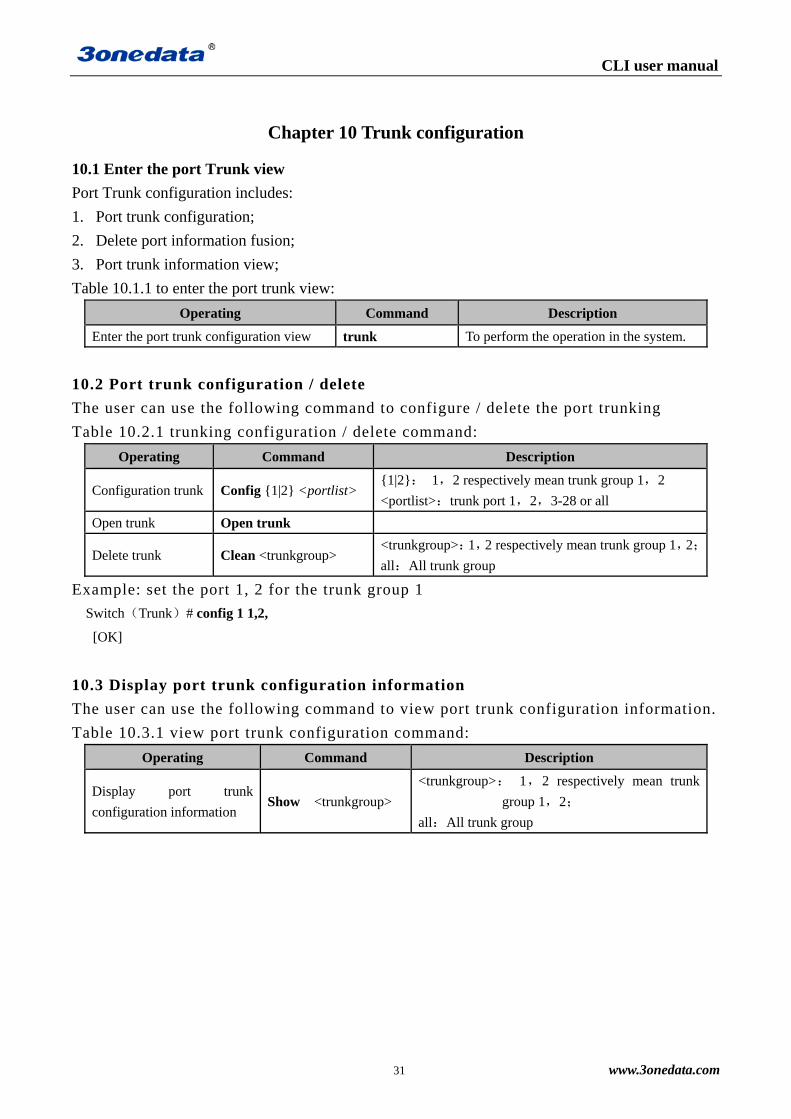
Chapter 10 Trunk configuration
10.1 Enter the port Trunk view
Port Trunk configuration includes:
1. Port trunk configuration;
2. Delete port information fusion;
3. Port trunk information view;
Table 10.1.1 to enter the port trunk view:
Operating Command Description
Enter the port trunk configuration view trunk To perform the operation in the system.
10.2 Port trunk configuration / delete
The user can use the following command to configure / delete the port trunking
Table 10.2.1 trunking configuration / delete command:
Operating Command Description
Configuration trunk Config {1|2} <portlist> {1|2}: 1,2 respectively mean trunk group 1,2
<portlist>:trunk port 1,2,3-28 or all
Open trunk Open trunk
Delete trunk Clean <trunkgroup> <trunkgroup>:1,2 respectively mean trunk group 1,2;
all:All trunk group
Example: set the port 1, 2 for the trunk group 1
Switch(Trunk)# config 1 1,2,
[OK]
10.3 Display port trunk configuration information
The user can use the following command to view port trunk configuration information.
Table 10.3.1 view port trunk configuration command:
Operating Command Description
Display port trunk
configuration information Show <trunkgroup>
<trunkgroup>: 1,2 respectively mean trunk
group 1,2;
all:All trunk group

CLI user manual
32 www.3onedata.com
Chapter 11 MAC port lock
11.1 Enter the MAC port lock view
MAC port lock includes;
1. MAC port locking information display
2. Add the MAC port locking information
3. Remove the MAC port locking information
Table 11.1.1 into the MAC port to lock the view command:
Operating Command Description
Enter the MAC port lock view Access To perform the operation in the system
11.2 MAC port locking information display
Table 11.2.1 shows the MAC port locking information
Operating Command Description
Display MAC port lock view Show lock To perform the operation in the system
11.3 Add or remove MAC port locking information
Table 11.3.1 add or delete MAC port locking information
Operating Command Description
Add the MAC port locking
information
Add <macaddress>
<port>
Macaddress Unicast MAC address
Port 1-28
Remove the MAC port locking
information Delete<1-16> <1-16> MAC locked entries in the port
Example: add a MAC port locking information
Switch(Access)#add 02-00-00-00-00-00 2
To delete a MAC port locking information
Switch(Access)# Delete 1

CLI user manual
33 www.3onedata.com
Chapter 12 Email alarm configuration
12.1 Enter the Email alarm view
Email alert configuration including:
1. Displays the Email alarm information
2. Email alarm enable
3. To configure the mail server address
4. The allocation of the recipient's address
5. Configure the sender address and password
6. Configure mail time interval
7. Send test e-mail system
Table 12.1.1 to enter the email alarm configuration view
Operating Command Description
Enter the email alarm configuration view Email To perform the operation in the system
12.2 Displays the Email alarm information
Table 12.2.1 shows the email alarm information view
Operating Command Description
show the email alarm information view Show email To perform the operation in the system
12.3 Configure email alarm information
Table 12.3.1 to configure mail alarm information
Operating Command Description
Email alarm enable Set email {enable|disable}
The mail server address Set Server<mail-server> <mail-server> The mail server address
The address of the addressee Set recipient
<mail-address> <mail-address> Mail recipient address
The sender address and
password
Set send <mail-address>
<password>
<mail-address> <password> The sender
email address and password
Mail time interval Set interval {0|1|2|4|12|24}
0 At any time
1 1hour
2 2hour
4 4hour
12 12hour
24 24hour
Send test e-mail system send email Show mail sending status information

CLI user manual
34 www.3onedata.com
Chapter 13 Alarm configuration
13.1 Enter the alarm information view
Alarm configuration including:
1. Power alarm;
2. Port alarm;
3. Delete alarm information;
4. Alarm information view;
Table 13.1.1 enter the alarm configuration view:
Operating Command Description
Enter the alarm configuration view Alarm To perform the operation in the system
13.2 Alarm configuration / delete
The user can use the following command to configure alarm
Table 13.2.1 alarm configuration command:
Operating Command Description
Configure port alarm Port relay <portlist>
{enable|disable} <portlist>:Alarm ports 1,2,3-28 or all
Configuration power alarm Power relay {1|2|all}
{enable|disable}
{1|2|all}:Show the way power alarm
1:The first power supply;
2:The second way power
To turn off the alarm information Close alarm In view of the alarm
Example: Open Ports 1, 3, 5, 7 alarm
Switch(Alarm)# port relay 1,3,5,7 enable
port1 Alarm status: Enable
port3 Alarm status: Enable
port5 Alarm status: Enable
port7 Alarm status: Enable
Example: power off warning
Switch(Alarm)# close alarm
[OK]
13.3 Display the alarm information
The user can use the following command to view the alarm information
Table 13.3.1 view the alarm information command:

CLI user manual
35 www.3onedata.com
Operating Command Description
Show power alarm
information Show power {1|2|all}
{1|2|all}:Show the way power alarm
1: The first power supply;
2: The second way power
Show port alarm
information Show port <portlist> <portlist>:Alarm ports 1,2,3-28 or all
Example: set the alarm information port
Switch(Alarm)# show port all
Port:1 Alarm status: Disable LOS
Port:2 Alarm status: Disable LOS
Port:3 Alarm status: Disable LOS
Port:4 Alarm status: Disable LOS
Port:5 Alarm status: Disable LOS
Port:6 Alarm status: Disable LOS
Port:7 Alarm status: Disable LOS
``````

CLI user manual
36 www.3onedata.com
Chapter 14 Port mirroring
14.1 Enter the port mirroring view
Port mirroring configuration includes: 1. Port mirroring configuration; 2. Delete port mirroring; 3. View port mirroring; Table 14.1.1 to enter the port mirroring configuration view:
Operating Command Description
Enter the port mirroring configuration view Mirror To perform the operation in the system
14.2 Port mirroring configuration / delete
The user can use the following command to port mirroring configuration / delete.
Table 14.2.1 port mirroring configuration / delete command:
Operating Command Description
Port mirroring
configuration Config {0|1|2} <mirror_port> <port>
{0|1|2}:Data type
0:Collect all the data representation;
1:The export data acquisition;
2:Entrance data acquisition
< mirror_port >:Mirror port 1,2,3-28
<port>:Acquisition port
Port mirroring
delete Close mirror In view of the port mirroring
Example: the allocation of port 3 to collect all the data ports 1 and 2.
Switch(mirror)# config 0 1-2 3
Mirror_portlist:1,2 collect_port:3 all data
14.3 Display port mirroring information
Table 14.3.1 view port mirroring information command:
Operating Command Description
Display port mirroring information Show mirror In view of the port mirroring

CLI user manual
37 www.3onedata.com
Chapter 15 Time configuration
15.1 In view of the Time configuration
Time allocation: 1. Time display configuration information 2. Time to enable 3. The world time zone selection 4. The address of the NTP server Table 15.1.1 into the time allocation view
Operating Command Description
Into the time allocation view Time To perform the operation in the system
15.2 The allocation of time allocation view
Table 15.2.1 into the allocation of time allocation view
Operating Command Description
Time to enable Time {enable|disable}
The world time zone selection Zone <time-zone> [-12 - +12] The world time zone
The address of the NTP server server <ntp-server> The address of the NTP server

CLI user manual
38 www.3onedata.com
Chapter 16 Static multicast configuration
16.1 In the static multicast address filter configuration view
Static multicast configuration includes: 1. Add static multicast address; 2. Remove the multicast address; 3. To view the multicast address; Table 16.1.1 into the static multicast view command:
Operating Command Description
In view of the static multicast Multicast To perform the operation in the system
16.2 Add / remove static multicast address
Users can use the following command to add / remove static multicast address
Table 16.2.1 multicast address add / delete command:
Operating Command Description
Add multicast address Add <macaddress> <portlist>
<macaddress> : A multicast address, the
format of XY-XX-XX-XX-XX-XX, X for
any sixteen hexadecimal number
<portlist>: port 1,2,3-28 or all
Delete multicast address Delete <1-15> <1-15> A multicast address entry
Example: add a multicast address 01-22-33-44-55-66, members of the port is 1, 2, 3.
Switch(Multicast) # add 01-22-33-44-55-66 1,2,3
MAC: 01-22-33-44-55-66 Port: 1,2,3
[OK]
16.3 Static multicast address allocation
The user can view the static multicast address the following command
Table 16.3.1 view static multicast address command:
Operating Command Description
view static multicast address Show multicast In the implementation of multicast.
CLI user manual
39 www.3onedata.com
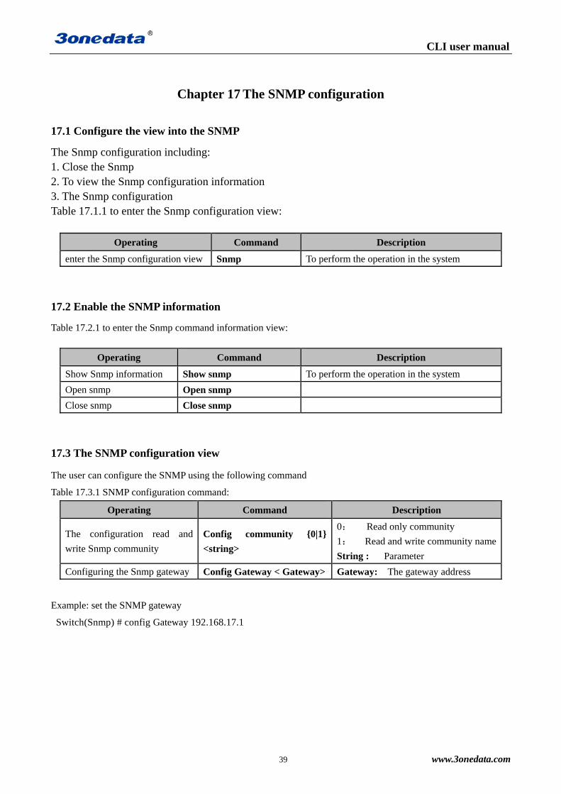
Chapter 17 The SNMP configuration
17.1 Configure the view into the SNMP
The Snmp configuration including: 1. Close the Snmp 2. To view the Snmp configuration information 3. The Snmp configuration Table 17.1.1 to enter the Snmp configuration view:
Operating Command Description
enter the Snmp configuration view Snmp To perform the operation in the system
17.2 Enable the SNMP information
Table 17.2.1 to enter the Snmp command information view:
Operating Command Description
Show Snmp information Show snmp To perform the operation in the system
Open snmp Open snmp
Close snmp Close snmp
17.3 The SNMP configuration view
The user can configure the SNMP using the following command
Table 17.3.1 SNMP configuration command:
Operating Command Description
The configuration read and
write Snmp community
Config community {0|1}
<string>
0: Read only community
1: Read and write community name
String : Parameter
Configuring the Snmp gateway Config Gateway < Gateway> Gateway: The gateway address
Example: set the SNMP gateway
Switch(Snmp) # config Gateway 192.168.17.1

CLI user manual
40 www.3onedata.com
Chapter 18 Port Statistics
18.1 Enter the port statistical configuration view
Port statistics: 1. Statistics port number and type 2. Clean up the count the number of frames 3. Statistics port flow 4. Clean up the total flow 5. The MAC address table Table 18.1.1 to enter the port statistical configuration view:
Operating Command Description
Enter the port statistical view Statistics To perform the operation in the system
18.2 Port Statistics configuration view
Table 18.2.1 to enter the port statistical configuration view
Operating Command Description
Statistics port number and type Show frames <port> <port> 1-28
Clean up the count the number of frames Clean frames
Statistics port flow Show traffic <port> <port> 1-28
Clean up the total flow Clean traffic
Example: the port number and types of statistics 1
Switch(Statistics) #show frames 1

CLI user manual
41 www.3onedata.com
Chapter 19 System management
19.1 Enter the System management configuration view
System management includes: 1. System timeout; 2. The default gateway, IP address configuration; 3. The user name, password configuration; 4. Device IP, subnet mask, default gateway, see; 5. Restore factory settings; 6. Upload, download the configuration file 7. The system upgrade Table 19.1.1 into the system management view commands:
Operating Command Description
In view of system management Manage To perform the operation in the system
19.2 System timeout
Users can use the following command to set the system time
Table 19.2.1 system timeout command:
Operating Command Description
System timeout setting Set <time_out> <time_out>:The system timeout, value of [0-60], the unit
minute, a default timeout value of 5 minutes
Example: set the system time is 10 minutes
Switch (manage)# set 10
[OK]
The system is used to define the time, when to enter the CLI configuration mode, do not do any operation
timeout. The system after a timeout will automatically jump to the user mode, the new username and password
authentication.
19.3 IP address and default gateway setting
The user can set the following command equipment IP, default gateway address
Table 19.3.1 device IP address, default gateway address setting:

CLI user manual
42 www.3onedata.com
Operating Command Description
The device IP address
configuration Ip <A.B.C.D> <A1.B1.C1.D1>
<A.B.C.D>:ip address
<A1.B1.C1.D1>:The subnet mask
The default gateway
configuration Gateway <A.B.C.D> <A.B.C.D>:The gateway address
Example: the equipment configuration for 192.168.254 IP 255.255.255.0, subnet mask, default gateway for
192.168.1.1
Switch(Manage)# ip 192.168.1.254 255.255.255.0
[OK]
Switch(Manage)# gateway 192.168.1.1
[OK]
19.4 User name, password settings
The user can set the user name, password following command
Table 19.4.1 user name, password settings:
Operating Command Description
User name setting Hostname <hostname> <hostname>:The user name string
User password setting Password <password> <password> <password>:The user password string
19.5 Display device IP, subnet mask, default gateway
The following command to check the equipment available to the user IP, subnet mask, default
gateway
Table 19.5.1 devices IP, subnet mask, default gateway.
Operating Command Description
Show device IP, subnet mask, default gateway show net_address To perform the operation in the
system manage
Example: check the equipment IP, subnet mask, default gateway address
Switch(manage)# show net_address
Device gateway : 192.168.1.1
Device mask address : 255.255.255.0
Device IP address : 192.168.1.254

CLI user manual
43 www.3onedata.com
19.6 Restore factory settings
The user can restore to factory settings following command equipment
Table 19.6.1 restores factory settings command:
Operating Command Description
Restore the device to
factory settings Restore To perform the operation in the system manage
Example: To restore the device to factory settings
Switch(manage)# restore
Restore Settings or not ? (yes/no) yes //Y
Wait..
19.7 Upload, download the configuration file
Through the super terminal, users can upload and download the configuration file, the following
command
Table 19.7.1 upload, download the configuration file.
Operating Command Description
Upload configuration file Upload File suffix (.Cfg)
To download the configuration file Download File suffix (.Cfg)
To download the configuration file as follows:
1. Enter the command:
Switch (manage) # download
Please select file path and ready to receive file.
Or press [Esc] to quit.
2. Super terminal and to select file folder
[transfer] →[To receive the file] →[browse] →[Select the folder] →[Users want to download folder] →
[OK] → [Use receiving protocol] →[Xmodem] →[Receive] →[To receive the file name] →[The user to
save the file name, the suffix.Cfg]] →[OK]
Upload configuration steps are as follows
1. Enter the command:
System_manage# upload
Please send configuration file, or press [Esc] to quit .
CCCCCCCCCCC
Explain: From the input upload command and the emergence of the first C start, no operation in 2 minutes,
the system will automatically exit

CLI user manual
44 www.3onedata.com
2. Super terminal and choose to upload the configuration file, the suffix.Cfg
[transfer] →[Send the file] →[browse] →[Select the folder] →[Users to upload the configuration file]
→[OPEN] → [Use receiving protocol] →[Xmodem]→[Send]
19.8 The system upgrade
Through the super terminal, users can upgrade the following command file system (Before the
upgrade, please confirm the correctness of the file)
Table 19.8.1 system upgrade.
Operating Command Description
The system upgrade Upgrade File suffix (.Bin)
The following steps to upgrade the system file
1. Enter the command:
Switch(manage)# upgrade
Please send upgrade file, or press [Esc] to quit .
CCCCCCCCCCCCCCCCCCCCCCCCCCCCCCCCCCCCCCCCCCCCCCC
2. Configure HyperTerminal and choose to upload the file, the suffix (.bin)
[Transfer] →[Send the file] →[browse] →[Select the folder] →[Users want to upgrade the configuration
file] →[Open] →[The use of Transfer protocol] →[Xmodem] →[Send]