Embed Size (px)
Citation preview
SAVE THESE INSTRUCTIONS FOR FUTURE REFERENCE
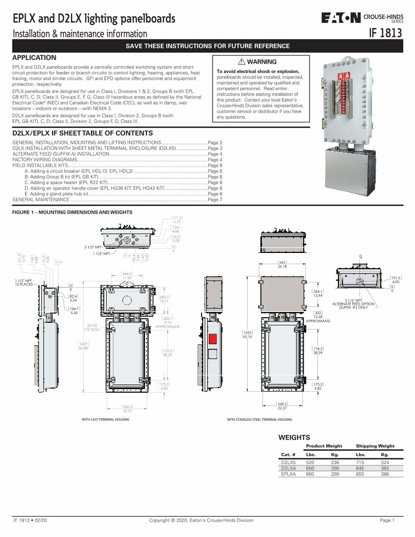
IF 1813EPLX and D2LX lighting panelboardsInstallation & maintenance information
IF 1813 • 02/20 Copyright © 2020, Eaton’s Crouse-Hinds Division Page 1
WARNING
To avoid electrical shock or explosion, panelboards should be installed, inspected, maintained and operated by qualified andcompetent personnel. Read entire instructions before starting installation of this product. Contact your local Eaton’s Crouse-Hinds Division sales representative, customer service or distributor if you have any questions.
!APPLICATIONEPLX and D2LX panelboards provide a centrally controlled switching system and short circuit protection for feeder or branch circuits to control lighting, heating, appliances, heat tracing, motor and similar circuits. GFI and EPD options offer personnel and equipment protection, respectively.
EPLX panelboards are designed for use in Class I, Divisions 1 & 2, Groups B (with EPL GB KIT), C, D; Class II, Groups E, F, G; Class III hazardous areas as defined by the National Electrical Code® (NEC) and Canadian Electrical Code (CEC), as well as in damp, wet locations – indoors or outdoors – with NEMA 3.
D2LX panelboards are designed for use in Class I, Division 2, Groups B (withEPL GB KIT), C, D; Class II, Division 2, Groups F, G; Class III.
FIGURE 1 – MOUNTING DIMENSIONS AND WEIGHTS
D2LX/EPLX IF SHEET TABLE OF CONTENTSGENERAL INSTALLATION, MOUNTING AND LIFTING INSTRUCTIONS ...................................Page 2D2LX INSTALLATION WITH SHEET METAL TERMINAL ENCLOSURE (D2LXS) ........................Page 3ALTERNATE FEED (SUFFIX A) INSTALLATION ..........................................................................Page 4FACTORY WIRING DIAGRAMS...................................................................................................Page 4FIELD INSTALLABLE KITS ..........................................................................................................Page 6 A. Adding a circuit breaker (EPL HDL13; EPL HDL2) ........................................................Page 6 B. Adding Group B kit (EPL GB KIT) ..................................................................................Page 6 C. Adding a space heater (EPL R22 KIT) ............................................................................Page 6 D. Adding an operator handle cover (EPL HG36 KIT; EPL HG42 KIT) ................................Page 6 E. Adding a gland plate hub kit ..........................................................................................Page 6GENERAL MAINTENANCE ........................................................................................................Page 7
165565.16
718.528.29
568.222.37
32212.68
APPROXIMATE
354.113.94
66526.18
173.26.82
718.528.29
383.715.11
444.517.50
568.222.37
232.79.16
APPROXIMATE
173.26.82
159762.88
[M12]1/2" BOLT
0 076.2
3.00
124
4.88
171.
56.
75
00
82.43.24
134.75.30
1 1/2" NPT12 PLACES
00
76.23.00
1244.88
171.56.75
0 090
.43.
56 143
5.63
3 1/2" NPT
1 1/2" NPT
00
101.54.00
CL
3 1/2" NPTALTERNATE FEED OPTION
(SUFFIX 'A') ONLY
WITH CAST TERMINAL HOUSING WITH STAINLESS STEEL TERMINAL HOUSING
Product Weight Shipping Weight
Cat. # Lbs. Kg. Lbs. Kg.
D2LXS 520 236 715 324D2LXA 650 295 845 383EPLXA 660 299 855 388
WEIGHTS
165565.16
718.528.29
568.222.37
32212.68
APPROXIMATE
354.113.94
66526.18
173.26.82
718.528.29
383.715.11
444.517.50
568.222.37
232.79.16
APPROXIMATE
173.26.82
159762.88
[M12]1/2" BOLT
0 076.2
3.00
124
4.88
171.
56.
75
00
82.43.24
134.75.30
1 1/2" NPT12 PLACES
00
76.23.00
1244.88
171.56.75
0 090
.43.
56 143
5.63
3 1/2" NPT
1 1/2" NPT
00
101.54.00
CL
3 1/2" NPTALTERNATE FEED OPTION
(SUFFIX 'A') ONLY
WITH CAST TERMINAL HOUSING WITH STAINLESS STEEL TERMINAL HOUSING
IF 1813 • 02/20 Copyright © 2020, Eaton’s Crouse-Hinds Division Page 2
WARNING
To avoid personal injury or damage to the panelboard assembly, always securely fasten the cast aluminum breaker housing before securing the terminal housing.
!
WARNING
To avoid the risk of explosion, always clean both flat joint surfaces of body and cover before closing. Dirt or foreign material must not accumulate on flat joint surfaces. Surfaces must seat fully against each other to provide a proper explosionproof joint.
!
WARNING
To avoid the risk of explosion, do not add or enlarge conduit entries in cast enclosures.
!
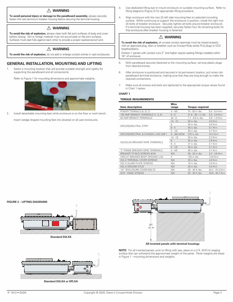
GENERAL INSTALLATION, MOUNTING AND LIFTING1. Select a mounting location that will provide suitable strength and rigidity for
supporting the panelboard and all components.
Refer to Figure 1 for mounting dimensions and approximate weights.
2. Install detachable mounting feet while enclosure is on the floor or work bench.
Insert wedge shaped mounting feet into dovetail on all cast enclosures.
3. Use dedicated lifting eye to mount enclosure on suitable mounting surface. Refer to lifting diagrams (Figure 2) for appropriate lifting procedure.
4. Align enclosure with the two (2) left side mounting feet on selected mounting surface. While continuing to support the enclosure in position, install the right two (2) bolts of breaker enclosure. Securely tighten all bolts around breaker enclosure. If a terminal housing has been supplied, securely fasten four (4) remaining bolts for that enclosure after breaker housing is fastened.
WARNING
To avoid the risk of explosion, all unused conduit openings must be closed properly with an approved plug, drain or breather such as Crouse-Hinds series PLG plugs or ECD breather/drains.
Division 1 panels with conduit runs 2” and higher require sealing fittings installed within 18” of enclosure.
!
5. With panelboard securely fastened to the mounting surface, remove plastic plugs from desired entries.
6. After enclosure is positioned and secured in its permanent location, pull wires into panelboard terminal enclosure, making sure that they are long enough to make the required connections.
7. Make sure all screws and bolts are tightened to the appropriate torque values found in Chart 1 below.
CHART 1
TORQUE REQUIREMENTS
Item descriptionWire range Torque required
POWER TEMINALS (A, B, C) 4 - 4/0 74 - 83 in.-lbs. 8.4 - 9.4 N-m100 AMP BRANCH TERMINALS (1, 3, 5) 6 - 0 21.8 - 26.1 in.-lbs. 2.5 - 2.9 N-m50 AMP BRANCH TERMINALS 24 - 8 7.1 - 8.9 in.-lbs. 0.8 - 1.0 N-m
GROUND/NEUTRAL STRIP
14 - 10 35 in.-lbs. 4.0 N-m8 40 in.-lbs. 4.5 N-m6 - 4 45 in.-lbs. 5.1 N-m2 - 1/0 50 in.-lbs. 5.7 N-m
GROUND/NEUTRAL & CHASSIS LUGS (3/8”) 6 - 350 MCM 375 in.-lbs. 42.4 N-m
QUICKLAG BREAKER WIRE TERMINALS
14 - 10 20 in.-lbs. 2.3 N-m8 25 in.-lbs. 2.8 N-m6 - 4 27 in.-lbs. 3.1 N-m3 - 1/0 45 in.-lbs. 5.1 N-m
‘F’ FRAME BREAKER WIRE TERMINALS 3 - 4/0 50 in.-lbs. 5.7 N-mBREAKER TO BUS SCREWS (#10) N/A 28 - 32 in.-lbs. 3.2 - 3.6 N-mCIRCUIT BREAKER BODY GROUND LUG 4 120 in.-lbs. 13.6 N-mD2L-S TERMINAL COVER SCREWS N/A 35 in.-lbs. 4.0 N-mD2L-S GLAND PLATE SCREWS N/A 18 in.-lbs. 2.0 N-mD2L-S GROUND STUD N/A 35 in.-lbs. 4.0 N-m1/2” ENCLOSURE COVER BOLTS N/A 40 - 45 ft.-lbs. 54.2 - 61.0 N-m5/16” HINGE SCREWS N/A 25 - 30 ft.-lbs. 33.9 - 40.7 N-m
FIGURE 2 – LIFTING DIAGRAMS
Standard D2LXA or EPLXA
All inverted panels with terminal housings
NOTE: For all inverted panels, prior to lifting with eye, place on a 2 ft. (0.61m) staging surface that can withstand the approximate weight of the panel. Panel weights are listed in Figure 1 - mounting dimensions and weights.
2FT.61 m
2FT.61 m
2FT.61 m
Standard D2LXS
IF 1813 • 02/20 Copyright © 2020, Eaton’s Crouse-Hinds Division Page 3
D2L INSTALLATION WITH SHEET METAL TERMINAL ENCLOSURE (D2LX)Refer to the general installation instructions before proceeding.
CAUTION
To avoid the risk of water ingress, when removing the gland plates, do not damage or compromise the gasket. Contact Crouse-Hinds for replacement gland plates if damaged.
!
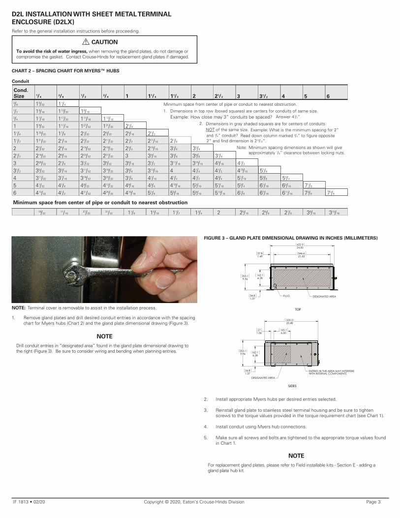
CHART 2 – SPACING CHART FOR MYERS™ HUBS
Conduit
6
315/16
Cond. Size 1/4
3/81/2
3/4 1 11/4 11/2 2 21/2 3 31/2 4 5
3/8 15/32 11/4 1/2 15/16 113/32 19/16 3/4 17/16 117/32 111/16 113/16
1 19/32 111/16 127/32 131/32 21/8
11/4 125/32 17/8 21/32 25/32 25/16 21/2
11/2 131/32 21/16 27/32 211/32 21/2 211/16 27/8
2 27/32 25/16 215/32 219/32 23/4 215/16 31/8 33/8
21/2 215/32 29/16 223/32 227/32 3 33/16 33/8 35/8 37/8
3 225/32 27/8 31/32 35/32 35/16 31/2 311/16 315/16 43/16 41/2
31/2 33/32 33/16 311/32 315/32 35/8 313/16 4 41/4 41/2 413/16 51/8
4 311/32 37/16 319/32 323/32 37/8 41/16 41/4 41/2 43/4 51/16 53/8 53/4
5 41/32 41/8 49/32 413/32 49/16 43/4 415/16 53/16 57/16 53/4 61/16 63/16 71/8
6 413/32 41/2 421/32 425/32 415/16 51/8 55/16 59/16 513/16 61/8 67/16 611/16 73/8 73/4
Minimum space from center of pipe or conduit to nearest obstruction
19/3211/16
27/3231/32 11/8 15/16 11/2 13/4 2 25/16 25/8 27/8 39/16
Minimum space from center of pipe or conduit to nearest obstruction.
1. Dimensions in top row (boxed squares) are centers for conduits of same size.
Example: How close may 3” conduits be spaced?
Answer 41/2”.
2. Dimensions in gray shaded squares are for centers of conduits NOT of the same size.
Example: What is the minimum spacing for 2” and 3/4” conduit?
Read down column marked 3/4” to figure opposite 2” and find dimension is 219/32”.
Note: Minimum spacing dimensions as shown will give approximately 1/8” clearance between locking nuts.
NOTE: Terminal cover is removable to assist in the installation process.
1. Remove gland plates and drill desired conduit entries in accordance with the spacing chart for Myers hubs (Chart 2) and the gland plate dimensional drawing (Figure 3).
NOTE
Drill conduit entries in “designated area” found in the gland plate dimensional drawing to the right (Figure 3). Be sure to consider wiring and bending when planning entries.
FIGURE 3 – GLAND PLATE DIMENSIONAL DRAWING IN INCHES (MILLIMETERS)
2. Install appropriate Myers hubs per desired entries selected.
3. Reinstall gland plate to stainless steel terminal housing and be sure to tighten screws to the torque values provided in the torque requirement chart (see Chart 1).
4. Install conduit using Myers hub connections.
5. Make sure all screws and bolts are tightened to the appropriate torque values found in Chart 1.
NOTE
For replacement gland plates, please refer to Field installable kits - Section E - adding a gland plate hub kit.
520.220.48
253.19.96
165.16.50
271.06
162.16.38
34.81.37
DESIGNATED AREA
ENTRIES IN THIS AREA MAY INTERFEREWITH INTERNAL COMPONENTS.
622.324.50
253.19.96
162.16.38
34.81.37
546.621.52
37.81.49
PLUG DESIGNATED AREA
TOP SIDES
520.220.48
253.19.96
165.16.50
271.06
162.16.38
34.81.37
DESIGNATED AREA
ENTRIES IN THIS AREA MAY INTERFEREWITH INTERNAL COMPONENTS.
622.324.50
253.19.96
162.16.38
34.81.37
546.621.52
37.81.49
PLUG DESIGNATED AREA
TOP SIDES
IF 1813 • 02/20 Copyright © 2020, Eaton’s Crouse-Hinds Division Page 4
ALTERNATE FEED (SUFFIX A) INSTALLATIONRefer to the general installation instructions before proceeding.
WARNING
To avoid the risk of explosion or equipment damage, do not scratch or damage flat joint flame path on either cover or body. Always clean both body and cover of dust and foreign particles prior to closing. Dirt or foreign material must not accumulate on flat joint surfaces.
!
1. Unthread cover bolts from breaker enclosure and swing open on its hinges.
2. Attach sealing fitting and pull wires through entrance.
3. Connect main power directly to main lugs (with main lug only panels) or to main circuit breaker. 4. Close enclosure cover, making sure that bolts are retracted to prevent scratches or
damage to the flange surface. Using only the bolts provided with the enclosure, tighten all bolts to 40-45 ft.-lbs. (191.5 - 215.4 N-m).
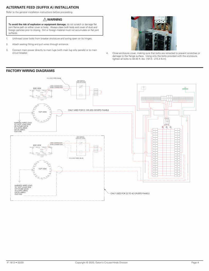
FACTORY WIRING DIAGRAMS
G20
G7
G21 G1
G8
G20
G5
G10G12
G2
G9
G16
G3
SIDE VIEW
G4
G13
TOP VIEW
G6
G15
G17
ODD CONNECTION
#16 AWG WIRES (BLUE)
G11
TEST SWITCHODD-OFF-EVEN
G14
G1
EVEN CONNECTION
G19 G3
G18 G4
G5
HARNESS WIRES LEADTO "HOT" LOAD SIDEOF FUTURE GFCB#16 AWG (RED)GFCB LABELSG22-G42
G6
G21
G2
HARNESS WIRES LEADTO "HOT" LOAD SIDEOF FUTURE GFCB#16 AWG (RED)GFCB LABELSG22-G42
G42
G41 G23
G22 G24
G25
G26
G27
ODD CONNECTIONEVEN CONNECTION
#16 AWG WIRES (BLUE)
TEST SWITCHODD-OFF-EVEN
G22G23
G24
G25
G26
G27
G28
G30G29
G31G32
G35
G36
G42
G38
G41G40
G39
G37
G34G33
TOP VIEW
SIDE VIEW
41
1638
16
17
2
26
842
14
19
4
28
1820
22
21
6
30
1026
6N
31
8
32
1232
42
33
13
10
34
18
B1
12
36
34N
30
12N
14
38
32N 10N
C3
11
16
40
30N40
A
15
18
42
34
8N
5
23
20
28N 4N
9
25
22
28 24
36
C
5
27
24
22
26
B
7
29
2
24
1
35
14
2N
A
3
37
440
38
39
636
20
ONLY USED FOR 21 OR LESS GFI/EPD PANELS
39N37N35N33N31N29N27N25N23N21N19N17N15N13N11N9N7N3N 5N
1N 7 9 11 13 15 17 19 21 23 25 27 29 31 33 35 37 39 41
41N
ONLY USED FOR 22 TO 42 GFI/EPD PANELS
IF 1813 • 02/20 Copyright © 2020, Eaton’s Crouse-Hinds Division Page 5
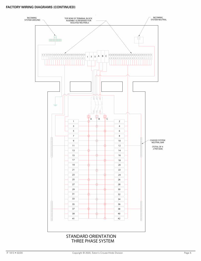
FACTORY WIRING DIAGRAMS (CONTINUED)
A B C41N7N 9N 11N 13N 15N
1513
33
31
21
19
17
39N37N35N33N31N29N27N25N23N21N19N17N
CBA
38N 20N 16N 14N22N 6N42N 18N 12N 10N40N 8N 4N36N 26N 24N 2N
40 363842 20263032 24 12 1018 816 6 414 22228
28N
34
30N32N34N
41393735333129272523211917
42
40
38
36
34
32
30
28
26
24
22
20
18
16
14
12
10
8
6
4
2
41
39
37
35
29
27
25
23
15
11
9
7
5
3
1
13
1171
93 5
3N 5N1N
STANDARD ORIENTATION THREE PHASE SYSTEM
INCOMING SYSTEM NEUTRAL
CHASSIS SYSTEM NEUTRAL BAR
(TOTAL OF 4 2 PER SIDE)
INCOMING SYSTEM GROUND
TOP ROW OF TERMINAL BLOCK ASSEMBLY IS RESERVED FOR
ISOLATED NEUTRALS
IF 1813 • 02/20 Copyright © 2020, Eaton’s Crouse-Hinds Division Page 6
FIELD INSTALLABLE KITS
A. Adding a circuit breaker (EPL HDL13; EPL HDL12)
WARNING
To avoid risk of explosion or equipment damage, do not scratch or damage flat joint flame path on either cover or body. Always clean both body and cover of dust and foreign particles prior to closing. Dirt or foreign material must not accumulate on flat joint surfaces.
!
1. De-energize panel, open circuit breaker enclosure and make sure bolts are retracted in cover.
2. Remove operator plug from desired position and install operator bearing.
3. Install operator shaft assembly until fully seated. Now turn shaft counter-clockwise 2 to 3 turns. Operator pin must be pointing down.
4. Install handle with screw and washer provided to shaft on the cover exterior.
5. Remove actuator plate and install circuit breaker in desired location. NOTE: Circuit breaker must be attached to chassis with torque of 30 in.-lbs. (0.21 N-m). See picture at bottom of page. For GFI and EPD breakers, the laid down neutral wire labeled for the circuit position should be installed in the breaker’s neutral terminal. The breaker pigtail should be connected to the closest of four (4) system neutral bars attached to the sides of the chassis. For non-GFI and EPD breakers, the laid down neutral wire must be connected to one of the four (4) system neutral bars.
6. Make sure to attach wire with appropriate torque value listed on circuit breaker. Locate pre-labeled wire corresponding with circuit breaker location and apply torque of 25 in-lbs. (0.17 N-m).
7. Remove actuator strap from actuator plate assembly.
FIGURE 6
FIGURE 4 FIGURE 5
8. Install and align slider in desired location and re-attach actuator strap.
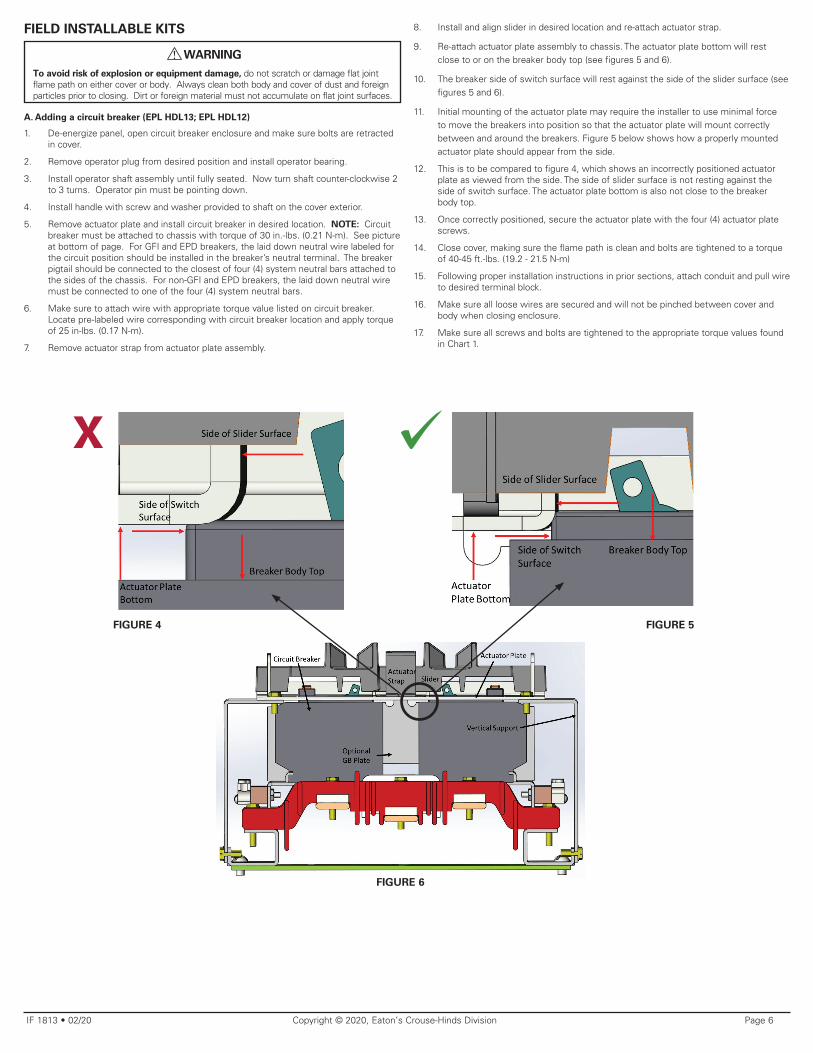
9. Re-attach actuator plate assembly to chassis. The actuator plate bottom will rest close to or on the breaker body top (see figures 5 and 6).
10. The breaker side of switch surface will rest against the side of the slider surface (see figures 5 and 6).
11. Initial mounting of the actuator plate may require the installer to use minimal force to move the breakers into position so that the actuator plate will mount correctly between and around the breakers. Figure 5 below shows how a properly mounted actuator plate should appear from the side.
12. This is to be compared to figure 4, which shows an incorrectly positioned actuator plate as viewed from the side. The side of slider surface is not resting against the side of switch surface. The actuator plate bottom is also not close to the breaker body top.
13. Once correctly positioned, secure the actuator plate with the four (4) actuator plate screws.
14. Close cover, making sure the flame path is clean and bolts are tightened to a torque of 40-45 ft.-lbs. (19.2 - 21.5 N-m)
15. Following proper installation instructions in prior sections, attach conduit and pull wire to desired terminal block.
16. Make sure all loose wires are secured and will not be pinched between cover and body when closing enclosure.
17. Make sure all screws and bolts are tightened to the appropriate torque values found in Chart 1.
Eaton’s Crouse-Hinds Division1201 Wolf Street, Syracuse, New York 13208 • USACopyright © 2020
IF 1813Revision 2
Revised 02/20Supercedes 05/17
All statements, technical information and recommendations contained herein are based on information and tests we believe to be reliable. The accuracy or completeness thereof are not guaranteed. In accordance with Eaton’s Crouse-Hinds Division’s “Terms and Conditions of Sale,” and since conditions of use are outside our control, the purchaser should determine the suitability of the product for his intended use and assumes all risk and liability whatsoever in connection herewith.
GENERAL MAINTENANCE
WARNING
To avoid the risk of explosion or equipment damage, do not scratch or damage flat joint flame path on either cover or body. Always clean both body and cover of dust and foreign particles prior to closing. Dirt or foreign material must not accumulate on flat joint surfaces.
!
WARNING
Disconnect all power upstream from panel prior to opening enclosure. Failure to do so could result in personnel injury or damage to equipment.
!
1. Frequent inspection should be made. A schedule for maintenance checks should be determined by the environment and frequency of use. It is recommended that it should be at least once a year.
2. Eaton’s Crouse-Hinds Division recommends an Electrical Preventative Maintenance Program as described in the National Fire Protection Association Bulletin NFPA 70B: Recommended Practice for Electrical Equipment Maintenance (www.nfpa.org).
3. It is recommended that GFI and EPD breakers be tested monthly.
4. Perform visual, electrical and mechanical checks on all components on a regular basis.
a. Visually check for undue heating evidenced by discoloration of wires or other components, damaged or worn parts or leakage evidenced by water or corrosion in the interior.
b. Electrically check to make sure that all connections are clean and tight.
c. Mechanically check that all parts are properly assembled and operating mechanisms move freely.
d. When checking torque on main lugs, it may be necessary to remove the actuator plate assembly to get access to the screws on the main lugs or branch circuit breakers.
5. A factory Waterguard desiccant pack has been provided. The purpose of this desiccant is to absorb and remove water on contact or from the atmosphere and protect the enclosed equipment from damage. The desiccant packet will expand 3 to 4 times its original size. Desiccant should be checked and replaced at regular equipment service intervals or every 3 to 6 months.
For replacement desiccant packets, order Cat. # WG22 (protects 2-3 cubic feet of air space and is recommended for terminal housings); or Cat. # WG33 (protects 4 to 5 feet of air space and is recommended for circuit breaker housings).
Waterguard is non-toxic, emits no fumes and generates no heat during use. No gloves, masks or special clothing is required to handle this product.
WARNING
To avoid the risk of explosion, always clean both ground joint surfaces of body and cover lightly with soft cloth or compressed air before closing. Dirt or foreign material must not accumulate on flat joint surfaces. Surfaces must seat fully against each other to provide a proper explosionproof seal.
!
6. Make sure all cover bolts are fully retracted into cover before closing cover on body. Close cover and start cover bolt threads by hand. Torque all cover bolts securely to 40-45 ft.-lbs. (19.2 - 21.5 N-m).
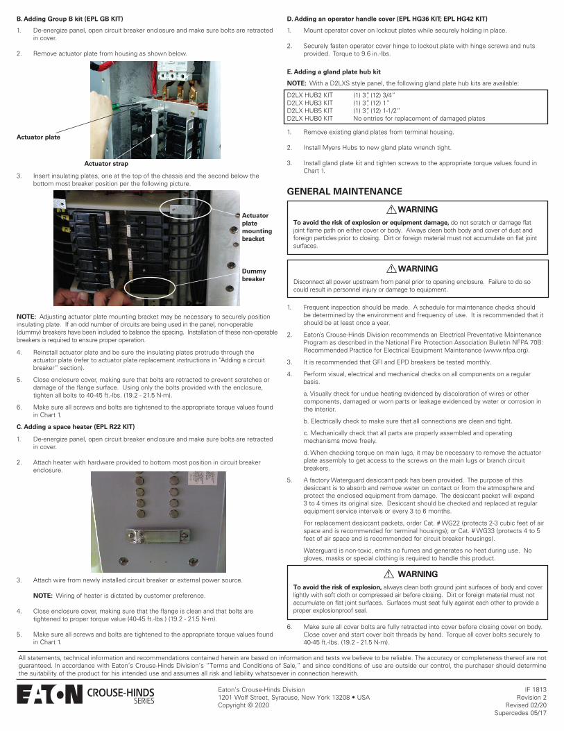
NOTE: Adjusting actuator plate mounting bracket may be necessary to securely position insulating plate. If an odd number of circuits are being used in the panel, non-operable (dummy) breakers have been included to balance the spacing. Installation of these non-operable breakers is required to ensure proper operation.
4. Reinstall actuator plate and be sure the insulating plates protrude through the actuator plate (refer to actuator plate replacement instructions in “Adding a circuit breaker” section).
5. Close enclosure cover, making sure that bolts are retracted to prevent scratches or damage of the flange surface. Using only the bolts provided with the enclosure, tighten all bolts to 40-45 ft.-lbs. (19.2 - 21.5 N-m).
6. Make sure all screws and bolts are tightened to the appropriate torque values found in Chart 1.
C. Adding a space heater (EPL R22 KIT)
1. De-energize panel, open circuit breaker enclosure and make sure bolts are retracted in cover.
2. Attach heater with hardware provided to bottom most position in circuit breaker enclosure.
3. Attach wire from newly installed circuit breaker or external power source.
NOTE: Wiring of heater is dictated by customer preference.
4. Close enclosure cover, making sure that the flange is clean and that bolts are tightened to proper torque value (40-45 ft.-lbs.) (19.2 - 21.5 N-m).
5. Make sure all screws and bolts are tightened to the appropriate torque values found in Chart 1.
D. Adding an operator handle cover (EPL HG36 KIT; EPL HG42 KIT)
1. Mount operator cover on lockout plates while securely holding in place.
2. Securely fasten operator cover hinge to lockout plate with hinge screws and nuts provided. Torque to 9.6 in.-lbs.
E. Adding a gland plate hub kit
NOTE: With a D2LXS style panel, the following gland plate hub kits are available:
D2LX HUB2 KIT (1) 3”, (12) 3/4”D2LX HUB3 KIT (1) 3”, (12) 1”D2LX HUB5 KIT (1) 3”, (12) 1-1/2”D2LX HUB0 KIT No entries for replacement of damaged plates
1. Remove existing gland plates from terminal housing.
2. Install Myers Hubs to new gland plate wrench tight.
3. Install gland plate kit and tighten screws to the appropriate torque values found in Chart 1.
B. Adding Group B kit (EPL GB KIT)
1. De-energize panel, open circuit breaker enclosure and make sure bolts are retracted in cover.
2. Remove actuator plate from housing as shown below.
Actuator plate
Actuator strap
3. Insert insulating plates, one at the top of the chassis and the second below the bottom most breaker position per the following picture.
Dummy breaker
Actuator plate mounting bracket