Embed Size (px)
Citation preview
1
AEROELASTIC TAILORING AND STRUCTURAL OPTIMISATION USING AN ADVANCED DYNAMIC AEROELASTIC FRAMEWORK
Noud P.M. Werter1, Roeland De Breuker1
1 Delft University of Technology Kluyverweg 1, 2629 HS, Delft, the Netherlands
Keywords: aeroelasticity, aeroelastic tailoring, wing design.
Abstract: Driven by a need to improve the efficiency of aircraft and reduce the fuel consumption, composite materials are applied extensively in the design of aircraft. A dynamic aeroelastic framework for the conceptual design of a generic composite wing structure is presented. The wing is discretized in several spanwise sections, where each section has a number of laminates throughout the cross-section, each having their own stiffness and thickness. The model uses a geometrically nonlinear beam model linearized around the nonlinear static aeroelastic equilibrium position coupled to a continuous-time state-space unsteady aerodynamic model to obtain the dynamic aeroelastic response. Two optimizations are run under aeroelastic and structural constraints: one, a quasi-isotropic wing to serve as a reference solution and two, a fully tailored wing clearly showing the benefit of aeroelastic tailoring and the use of the present framework for conceptual wing design.
1 INTRODUCTION
Driven by a need to improve the efficiency of aircraft and reduce the fuel consumption, composite materials are applied extensively in the design of aircraft. In addition to a high specific strength and stiffness, they also offer the designer the freedom to tailor the stiffness in desirable directions. One of the potential applications of this directional stiffness is aeroelastic tailoring, defined by Shirk et al.[1] as:
the embodiment of directional stiffness into an aircraft structural design to control aeroelastic deformation, static or dynamic, in such a fashion as to affect the aerodynamic and structural performance of that aircraft in a beneficial way.
An extensive summary of early research on aeroelastic tailoring of swept and unswept wings has been written by Hertz et al.[2] Several researchers have applied aeroelastic tailoring mainly for weight reduction of aircraft [3]–[5], gust load alleviation [6], [7], improvement of flutter speed [8], [9] and drag reduction.[10] Furthermore some research has been done on the effect of aeroelastic tailoring on the stability of supersonic aircraft[11], wings with external stores[12] and also in applications outside aerospace engineering.[13]
Early research performed by Librescu has focused on the aeroelastic tailoring of thin-walled beams,[14]–[16] which has more recently been extended by Qin and Librescu [11], [17]. The effect of variable stiffness along the span has been investigated by Dillinger et al.[18] using a shell model coupled to DLM in Nastran to do the static aeroelastic optimization of the top and bottom skin using lamination parameters and the laminate thickness. When looking at full wingbox tailoring including spars, Guo [5] investigates the effect of ply angle on the flutter
IFASD-2015-137
2
speed of an aerobatic aircraft wing. More recently Stodieck et al.[19] and Stanford et al.[20] investigated the effect of a linearly varying fibre angle on the aeroelastic response of a composite plate.
When looking at aeroelastic optimization, several optimization procedures have been applied to find the optimum layup for different objectives. Research has mainly focused on the use of a genetic algorithm for the optimization[20]–[23]. The main disadvantage of genetic algorithms is that they require a significant amount of function evaluations to find the optimum, especially when a large design space is considered. Guo [5] uses a gradient-based optimizer to optimize the wingbox fibre angles for a constant thickness, while Dillinger et al.[18] combines stiffness and thickness optimization, but only considers the top and bottom skin.
Within this field, the current paper describes the application of an aeroelastic analysis tool developed at the Delft University of Technology for the conceptual design of the wing box structure by means of aeroelastic tailoring. The model extends the current state-of-the-art by combining stiffness and thickness optimization of the complete wingbox including non-structural masses under dynamic aeroelastic constraints using a gradient-based optimizer and lamination parameters to not restrict the design space a priori.
The framework also shows the implementation of a novel unsteady aerodynamic model based on the unsteady vortex lattice method written in continuous-time state-space that allows for a fast and efficient analysis of the unsteady aerodynamics around aircraft wings without requiring a transformation to the frequency domain and back.
The proposed paper demonstrates the implementation of this dynamic aeroelastic framework including the implementation of external forces and non-structural masses, as is explained in sections 2 to 5. Finally the framework is applied to the optimisation of the one engine reference model, courtesy of DLR, showing the potential of the proposed framework for the structural optimisation of composite wings, as explained in section 6.
2 MODELING APPROACH
The goal of the dynamic aeroelastic analysis and optimization framework is to improve the conceptual design of aircraft wings by including aeroelasticity. Therefore, one of the key requirements of the framework is computational efficiency. For this purpose, the three-dimensional wing geometry is split in several spanwise sections, each having its own skin laminate distribution throughout the wing cross-section. These laminates are described using lamination parameters and the laminate thickness, since these define any composite laminate using a fixed number of continuous design variables, which allows for the use of more efficient optimizers.
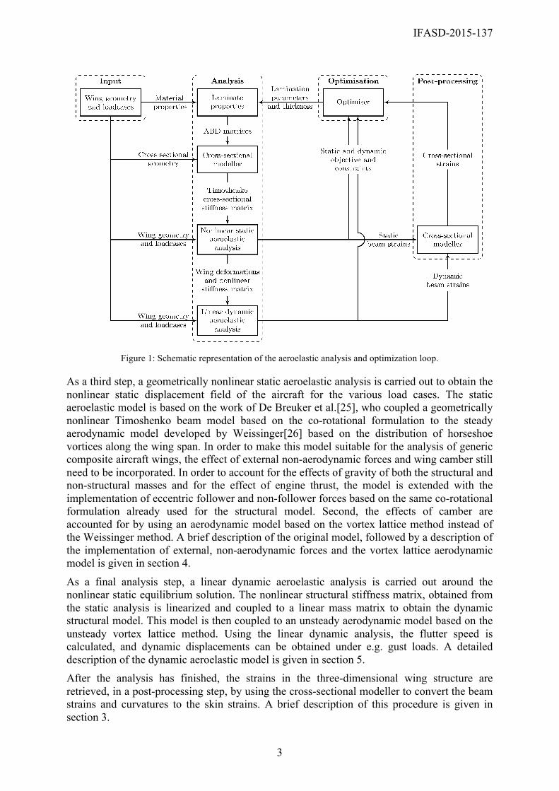
The aeroelastic analysis and optimization loop is depicted in figure 1, and starts with the definition of the wing geometry and load cases as inputs to the loop. Next, the composite laminate properties that are used for the wing skins and spars are determined based on the material properties given as input and the lamination parameters and thicknesses generated by the optimizer. In order to generate the beam model, these laminate properties, together with the cross-sectional geometry, are used to generate the Timoshenko cross-sectional stiffness matrix with respect to the beam reference axis, using the cross-sectional modeller developed by Ferede et al.[24] For completeness, a brief overview of this procedure will be given in section 3.
IFASD-2015-137
3
Figure 1: Schematic representation of the aeroelastic analysis and optimization loop.
As a third step, a geometrically nonlinear static aeroelastic analysis is carried out to obtain the nonlinear static displacement field of the aircraft for the various load cases. The static aeroelastic model is based on the work of De Breuker et al.[25], who coupled a geometrically nonlinear Timoshenko beam model based on the co-rotational formulation to the steady aerodynamic model developed by Weissinger[26] based on the distribution of horseshoe vortices along the wing span. In order to make this model suitable for the analysis of generic composite aircraft wings, the effect of external non-aerodynamic forces and wing camber still need to be incorporated. In order to account for the effects of gravity of both the structural and non-structural masses and for the effect of engine thrust, the model is extended with the implementation of eccentric follower and non-follower forces based on the same co-rotational formulation already used for the structural model. Second, the effects of camber are accounted for by using an aerodynamic model based on the vortex lattice method instead of the Weissinger method. A brief description of the original model, followed by a description of the implementation of external, non-aerodynamic forces and the vortex lattice aerodynamic model is given in section 4.
As a final analysis step, a linear dynamic aeroelastic analysis is carried out around the nonlinear static equilibrium solution. The nonlinear structural stiffness matrix, obtained from the static analysis is linearized and coupled to a linear mass matrix to obtain the dynamic structural model. This model is then coupled to an unsteady aerodynamic model based on the unsteady vortex lattice method. Using the linear dynamic analysis, the flutter speed is calculated, and dynamic displacements can be obtained under e.g. gust loads. A detailed description of the dynamic aeroelastic model is given in section 5. After the analysis has finished, the strains in the three-dimensional wing structure are retrieved, in a post-processing step, by using the cross-sectional modeller to convert the beam strains and curvatures to the skin strains. A brief description of this procedure is given in section 3.
IFASD-2015-137
4
Finally the static and dynamic responses, and the skin strains are fed into the optimizer as objective or constraint and a gradient-based optimizer is used to update the set of lamination parameters and thicknesses until a converged solution is found.
3 CROSS-SECTIONAL MODELLER
The cross-sectional modeller, as mentioned in the modeling approach, has two functions in the optimization loop. First, the cross-sectional properties have to be determined from the three dimensional wing model to obtain the equivalent one-dimensional properties. For this purpose a thin-walled cross-sectional modeller was developed by Ferede et al.[24] The cross-section is discretized in linear Hermitian shell elements having constant properties and can be any arbritrary open or closed, thin-walled, composite cross-section. Using a variational asymptotic approach, the Timoshenko cross-sectional stiffness matrix and the cross-sectional mass properties can be determined. Second, once the aeroelastic analysis has been completed, the cross-sectional modeller is used to recover the skin strains throughout the cross-section from the one-dimensional beam strains, to be able to assess potential skin failure. These skin strains include both the Euler-Bernouilli strains and the second-order free warping solution.
4 STATIC AEROELASTIC FRAMEWORK
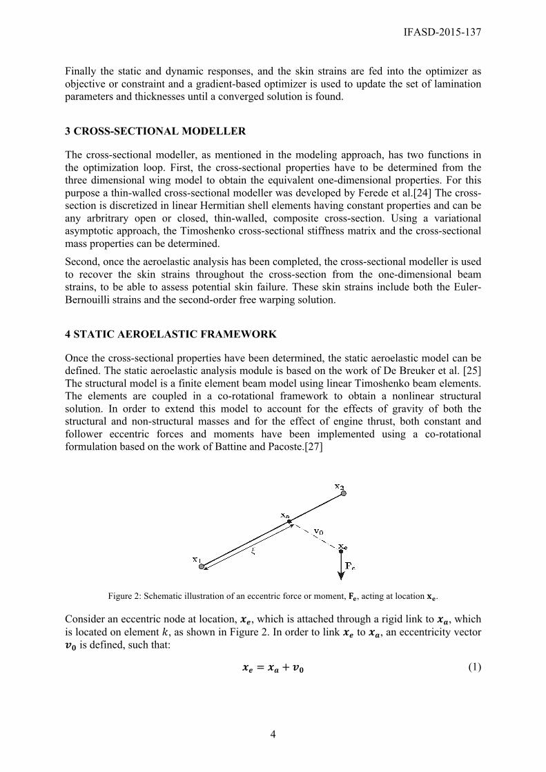
Once the cross-sectional properties have been determined, the static aeroelastic model can be defined. The static aeroelastic analysis module is based on the work of De Breuker et al. [25] The structural model is a finite element beam model using linear Timoshenko beam elements. The elements are coupled in a co-rotational framework to obtain a nonlinear structural solution. In order to extend this model to account for the effects of gravity of both the structural and non-structural masses and for the effect of engine thrust, both constant and follower eccentric forces and moments have been implemented using a co-rotational formulation based on the work of Battine and Pacoste.[27]
Figure 2: Schematic illustration of an eccentric force or moment, 𝐅𝐞, acting at location 𝐱𝐞.
Consider an eccentric node at location, 𝒙𝒆, which is attached through a rigid link to 𝒙𝒂, which is located on element 𝑘, as shown in Figure 2. In order to link 𝒙𝒆 to 𝒙𝒂, an eccentricity vector 𝒗𝟎 is defined, such that:
𝒙𝒆 = 𝒙𝒂 + 𝒗𝟎 (1)
IFASD-2015-137
5
In order to obtain the nodal force vector and stiffness contribution introduced by the eccentric forces and moments, the principle of virtual work is used. A transformation between the eccentric force and moment vector and the nodal force vector can be obtained by considering that both forces should perform the same external virtual work:
𝜹𝒑𝒆𝑻𝑭𝒆 = 𝜹𝒑𝑻𝑭 (2)
where 𝒑𝒆 contains the degrees of freedom of the eccentric node and 𝒑 contains the degrees of freedom of the corresponding beam element. Using equation (1) and deriving the transformation, the corresponding stiffness contribution and nodal force vector are obtained.
Cross-sectional properties
Material properties
Loading
Width 1 m 𝐸 10 MPa Tip 𝐹! = 600 𝑁 𝑀! = 0 𝑁𝑚
Height 1 m 𝐺 5 MPa Eccentric constant
𝐹! = 600 𝑁 𝑀! = −4000 𝑁𝑚
𝜌 1000 kg/m3 Eccentric follower
𝐹! = 300 𝑁 𝑀! = −2500 𝑁𝑚
Table 1: 45 deg circular bend beam properties
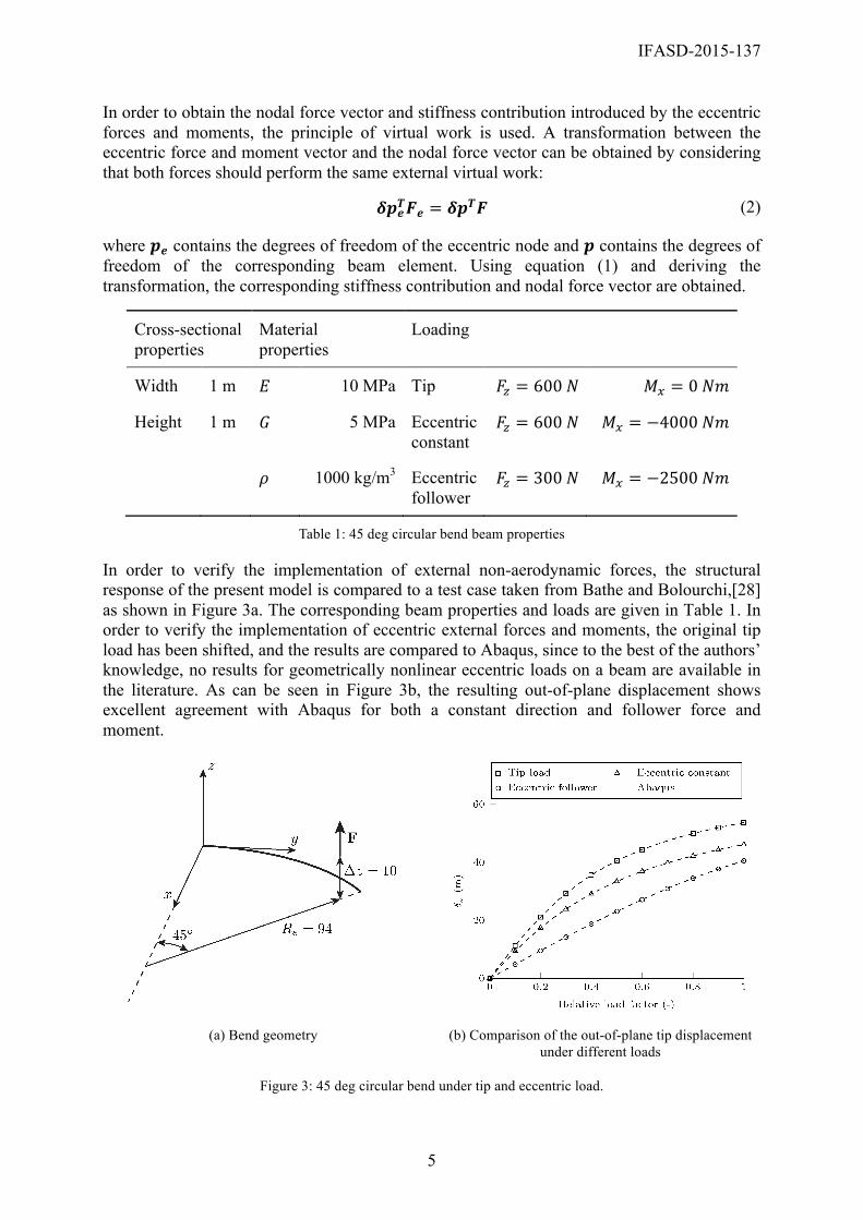
In order to verify the implementation of external non-aerodynamic forces, the structural response of the present model is compared to a test case taken from Bathe and Bolourchi,[28] as shown in Figure 3a. The corresponding beam properties and loads are given in Table 1. In order to verify the implementation of eccentric external forces and moments, the original tip load has been shifted, and the results are compared to Abaqus, since to the best of the authors’ knowledge, no results for geometrically nonlinear eccentric loads on a beam are available in the literature. As can be seen in Figure 3b, the resulting out-of-plane displacement shows excellent agreement with Abaqus for both a constant direction and follower force and moment.
(a) Bend geometry (b) Comparison of the out-of-plane tip displacement
under different loads
Figure 3: 45 deg circular bend under tip and eccentric load.
IFASD-2015-137
6
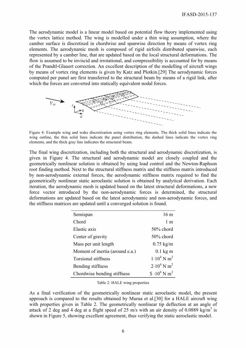
The aerodynamic model is a linear model based on potential flow theory implemented using the vortex lattice method. The wing is modelled under a thin wing assumption, where the camber surface is discretised in chordwise and spanwise direction by means of vortex ring elements. The aerodynamic mesh is composed of rigid airfoils distributed spanwise, each represented by a camber line, that are updated based on the local structural deformations. The flow is assumed to be inviscid and irrotational, and compressibility is accounted for by means of the Prandtl-Glauert correction. An excellent description of the modelling of aircraft wings by means of vortex ring elements is given by Katz and Plotkin.[29] The aerodynamic forces computed per panel are first transferred to the structural beam by means of a rigid link, after which the forces are converted into statically equivalent nodal forces.
Figure 4: Example wing and wake discretization using vortex ring elements. The thick solid lines indicate the wing outline, the thin solid lines indicate the panel distribution, the dashed lines indicate the vortex ring elements, and the thick gray line indicates the structural beam.
The final wing discretization, including both the structural and aerodynamic discretization, is given in Figure 4. The structural and aerodynamic model are closely coupled and the geometrically nonlinear solution is obtained by using load control and the Newton-Raphson root finding method. Next to the structural stiffness matrix and the stiffness matrix introduced by non-aerodynamic external forces, the aerodynamic stiffness matrix required to find the geometrically nonlinear static aeroelastic solution is obtained by analytical derivation. Each iteration, the aerodynamic mesh is updated based on the latest structural deformations, a new force vector introduced by the non-aerodynamic forces is determined, the structural deformations are updated based on the latest aerodynamic and non-aerodynamic forces, and the stiffness matrices are updated until a converged solution is found.
Semispan 16 m Chord 1 m Elastic axis 50% chord Center of gravity 50% chord Mass per unit length 0.75 kg/m Moment of inertia (around e.a.) 0.1 kg m Torsional stiffness 1⋅104 N m2
Bending stiffness 2⋅104 N m2 Chordwise bending stiffness 5 ⋅106 N m2
Table 2: HALE wing properties
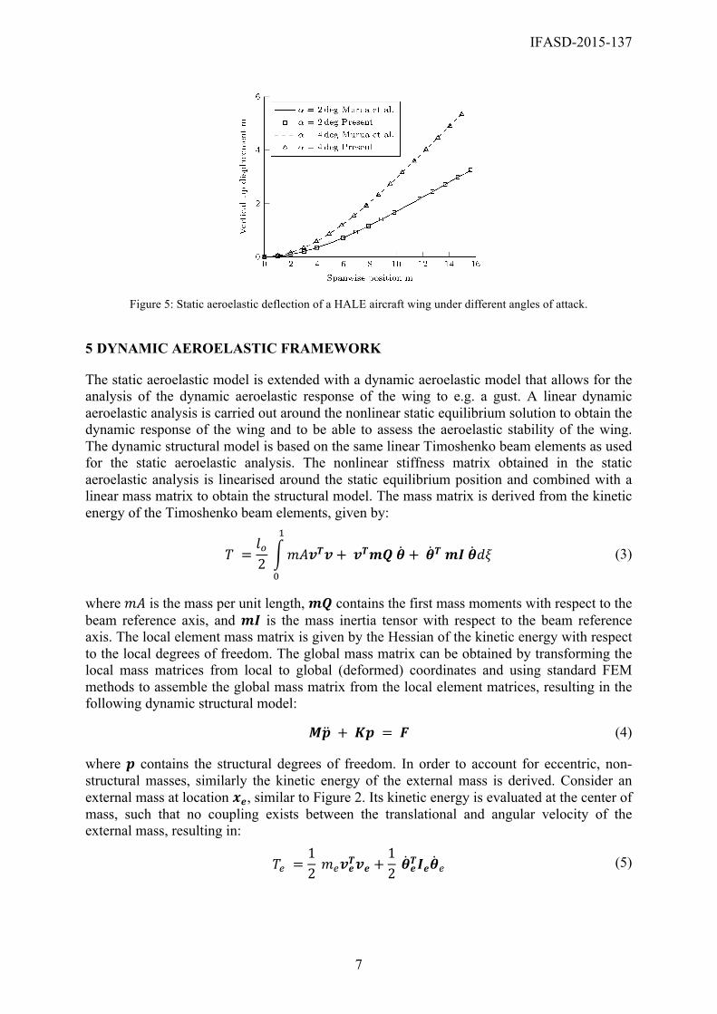
As a final verification of the geometrically nonlinear static aeroelastic model, the present approach is compared to the results obtained by Murua et al.[30] for a HALE aircraft wing with properties given in Table 2. The geometrically nonlinear tip deflection at an angle of attack of 2 deg and 4 deg at a flight speed of 25 m/s with an air density of 0.0889 kg/m3 is shown in Figure 5, showing excellent agreement, thus verifying the static aeroelastic model.
IFASD-2015-137
7
Figure 5: Static aeroelastic deflection of a HALE aircraft wing under different angles of attack.
5 DYNAMIC AEROELASTIC FRAMEWORK
The static aeroelastic model is extended with a dynamic aeroelastic model that allows for the analysis of the dynamic aeroelastic response of the wing to e.g. a gust. A linear dynamic aeroelastic analysis is carried out around the nonlinear static equilibrium solution to obtain the dynamic response of the wing and to be able to assess the aeroelastic stability of the wing. The dynamic structural model is based on the same linear Timoshenko beam elements as used for the static aeroelastic analysis. The nonlinear stiffness matrix obtained in the static aeroelastic analysis is linearised around the static equilibrium position and combined with a linear mass matrix to obtain the structural model. The mass matrix is derived from the kinetic energy of the Timoshenko beam elements, given by:
𝑇 =𝑙!2 𝑚𝐴𝒗𝑻𝒗+ 𝒗𝑻𝒎𝑸 𝜽+ 𝜽𝑻 𝒎𝑰 𝜽𝑑𝜉
!
!
(3)
where 𝑚𝐴 is the mass per unit length, 𝒎𝑸 contains the first mass moments with respect to the beam reference axis, and 𝒎𝑰 is the mass inertia tensor with respect to the beam reference axis. The local element mass matrix is given by the Hessian of the kinetic energy with respect to the local degrees of freedom. The global mass matrix can be obtained by transforming the local mass matrices from local to global (deformed) coordinates and using standard FEM methods to assemble the global mass matrix from the local element matrices, resulting in the following dynamic structural model:
𝑴𝒑 + 𝑲𝒑 = 𝑭 (4)
where 𝒑 contains the structural degrees of freedom. In order to account for eccentric, non-structural masses, similarly the kinetic energy of the external mass is derived. Consider an external mass at location 𝒙𝒆, similar to Figure 2. Its kinetic energy is evaluated at the center of mass, such that no coupling exists between the translational and angular velocity of the external mass, resulting in:
𝑇! =12 𝑚!𝒗𝒆𝑻𝒗𝒆 +
12 𝜽𝒆
𝑻𝑰𝒆𝜽! (5)
IFASD-2015-137
8
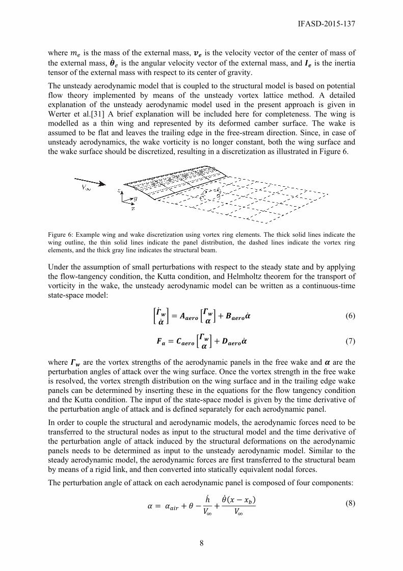
where 𝑚! is the mass of the external mass, 𝒗𝒆 is the velocity vector of the center of mass of the external mass, 𝜽! is the angular velocity vector of the external mass, and 𝑰𝒆 is the inertia tensor of the external mass with respect to its center of gravity. The unsteady aerodynamic model that is coupled to the structural model is based on potential flow theory implemented by means of the unsteady vortex lattice method. A detailed explanation of the unsteady aerodynamic model used in the present approach is given in Werter et al.[31] A brief explanation will be included here for completeness. The wing is modelled as a thin wing and represented by its deformed camber surface. The wake is assumed to be flat and leaves the trailing edge in the free-stream direction. Since, in case of unsteady aerodynamics, the wake vorticity is no longer constant, both the wing surface and the wake surface should be discretized, resulting in a discretization as illustrated in Figure 6.
Figure 6: Example wing and wake discretization using vortex ring elements. The thick solid lines indicate the wing outline, the thin solid lines indicate the panel distribution, the dashed lines indicate the vortex ring elements, and the thick gray line indicates the structural beam.
Under the assumption of small perturbations with respect to the steady state and by applying the flow-tangency condition, the Kutta condition, and Helmholtz theorem for the transport of vorticity in the wake, the unsteady aerodynamic model can be written as a continuous-time state-space model:
𝜞𝒘𝜶
= 𝑨𝒂𝒆𝒓𝒐𝜞𝒘𝜶 + 𝑩𝒂𝒆𝒓𝒐𝜶 (6)
𝑭𝒂 = 𝑪𝒂𝒆𝒓𝒐𝜞𝒘𝜶 +𝑫𝒂𝒆𝒓𝒐𝜶 (7)
where 𝜞𝒘 are the vortex strengths of the aerodynamic panels in the free wake and 𝜶 are the perturbation angles of attack over the wing surface. Once the vortex strength in the free wake is resolved, the vortex strength distribution on the wing surface and in the trailing edge wake panels can be determined by inserting these in the equations for the flow tangency condition and the Kutta condition. The input of the state-space model is given by the time derivative of the perturbation angle of attack and is defined separately for each aerodynamic panel. In order to couple the structural and aerodynamic models, the aerodynamic forces need to be transferred to the structural nodes as input to the structural model and the time derivative of the perturbation angle of attack induced by the structural deformations on the aerodynamic panels needs to be determined as input to the unsteady aerodynamic model. Similar to the steady aerodynamic model, the aerodynamic forces are first transferred to the structural beam by means of a rigid link, and then converted into statically equivalent nodal forces. The perturbation angle of attack on each aerodynamic panel is composed of four components:
𝛼 = 𝛼!"# + 𝜃 −
ℎ𝑉!+𝜃 𝑥 − 𝑥!
𝑉! (8)
IFASD-2015-137
9
where 𝛼!"# is the perturbance angle of attack induced by the free stream flow, 𝜃 is the elastic wing twist, − !
!! is the perturbance angle of attack introduced by the local plunge motion of
the wing, and ! !!!!!!
is the perturbance angle of attack introduced by the local pitch rate of the wing, where 𝑥 defines the location of the aerodynamic panel and 𝑥! defines the location of the beam axis. The local structural deformations are found by a linear interpolation of the nodal structural deformations to the spanwise aerodynamic stations.
Finally the structural state-space system given by equation (4) and the aerodynamic state-space system given by equation (6) and (7) can be directly coupled in a single state-space system resulting in: 𝒙 = 𝑨𝒔𝒔𝒙+ 𝑩𝒔𝒔𝜶𝒂𝒊𝒓 (9)
𝑭𝒑 = 𝑪𝒔𝒔𝒙+𝑫𝒔𝒔𝜶𝒂𝒊𝒓 (10)
where the state vector is given by 𝜞𝒘 𝜶𝒂𝒊𝒓 𝒑 𝒑 .
In order to verify the dynamic aeroelastic model, first the flutter speed for the HALE aircraft wing, as given in Table 2, is compared to the literature. The flutter speed is determined by increasing the velocity until the eigenvalues of the state matrix 𝑨𝒔𝒔 become unstable. As can be seen in Table 3, the results show excellent agreement.
𝑉! 𝜔!
Patil et al.[32] 31.75 m/s 23.60 rad/s
Murua et al.[30] 33 m/s 22 rad/s
Present 32.12 m/s 23.21 rad/s
Table 3: Flutter speed of a HALE aircraft wing
Semispan 12.192 m Chord 0.2032 m Elastic axis 43.7% chord Center of gravity 45.4% chord Mass per unit length 1.2943 kg/m Moment of inertia (around e.a.) 3.56⋅10-3 kg m Torsional stiffness 198.6 N m2
Bending stiffness 403.8 N m2 Eccentric mass 1.44 kg Chordwise location of the mass w.r.t. e.a. -0.083 m Moment of inertia (around mass c.g.) 8.50⋅10-3 kg m2
Table 4: Runyan and Sewall wing properties
IFASD-2015-137
10
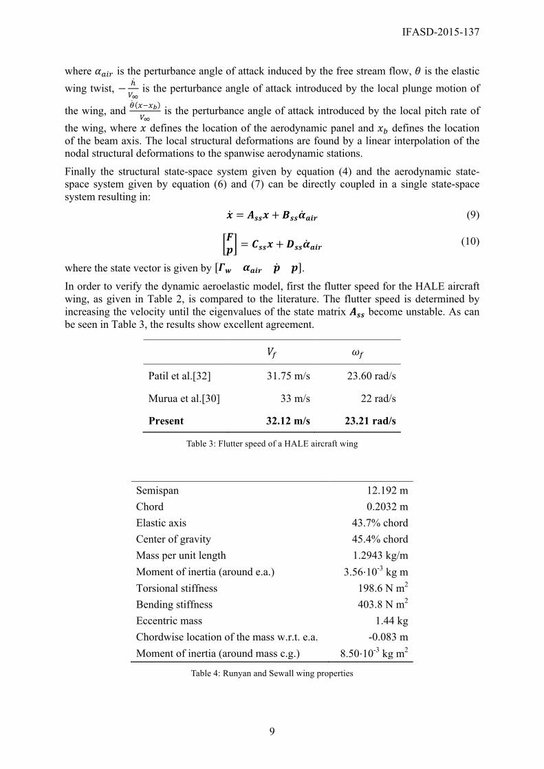
Second, in order to validate the implementation of the eccentric masses, the aeroelastic stability as predicted by the present model is compared to the experimental results of Runyan and Sewall.[33] The wing properties are given in Table 4 and the comparison is shown in Figure 7. When looking at the results, several things can be observed. First of all, the predicted flutter and divergence speed shows excellent agreement with the experiments, however, both the present model and Fazelzadeh et al.[34] overpredict the flutter frequency by 10-15%. This can probably be explained by inaccuracies between the modelling of the experiment and the actual experiment. Second, the present model predicts transition from flutter to divergence already at 0.406 m, while in the experiment the wing was close to divergence, but still fluttering. In general, however, the present results show good agreement with the experiments, thus validating the implementation of eccentric masses in the present model.
(a) Aeroelastic stability speed (b) Aeroelastic stability frequency
Figure 7: Aeroelastic stability and frequency of a wing with an eccentric mass at different spanwise locations.
6 AEROELASTIC TAILORING OF THE OERM
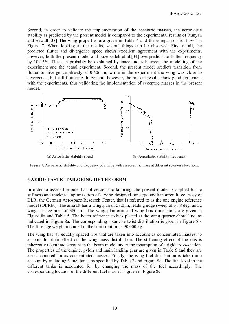
In order to assess the potential of aeroelastic tailoring, the present model is applied to the stiffness and thickness optimisation of a wing designed for large civilian aircraft, courtesy of DLR, the German Aerospace Research Center, that is referred to as the one engine reference model (OERM). The aircraft has a wingspan of 58.0 m, leading edge sweep of 31.8 deg, and a wing surface area of 380 m2. The wing planform and wing box dimensions are given in Figure 8a and Table 5. The beam reference axis is placed at the wing quarter chord line, as indicated in Figure 8a. The corresponding spanwise twist distribution is given in Figure 8b. The fuselage weight included in the trim solution is 90 000 kg.
The wing has 41 equally spaced ribs that are taken into account as concentrated masses, to account for their effect on the wing mass distribution. The stiffening effect of the ribs is inherently taken into account in the beam model under the assumption of a rigid cross-section. The properties of the engine, pylon and main landing gear are given in Table 6 and they are also accounted for as concentrated masses. Finally, the wing fuel distribution is taken into account by including 5 fuel tanks as specified by Table 7 and Figure 8d. The fuel level in the different tanks is accounted for by changing the mass of the fuel accordingly. The corresponding location of the different fuel masses is given in Figure 8c.
IFASD-2015-137
11
Spanwise location LE Mid TE
0 m 16.5% chord 40.0% chord 63.4% chord
2.79 m 16.5% chord 40.0% chord 63.4% chord
9.37 m 14.4% chord 40.9% chord 67.5% chord
20.06 m 18.5% chord 55.1% chord
29.00 m 28.6% chord 68.8% chord
Table 5: Spar locations
(a) Wing planform indicating the wingbox in dark grey, the spar locations by the dashed lines, and the beam reference axis by the dash-dotted line.
(b) Twist distribution
(c) Non-structural mass locations (d) Fuel mass distribution
Figure 8: OERM wing properties
IFASD-2015-137
12
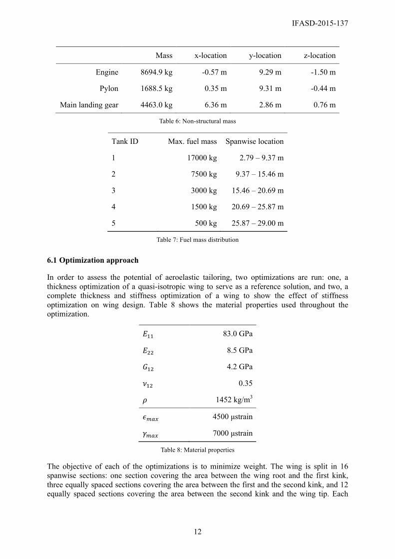
Mass x-location y-location z-location
Engine 8694.9 kg -0.57 m 9.29 m -1.50 m
Pylon 1688.5 kg 0.35 m 9.31 m -0.44 m
Main landing gear 4463.0 kg 6.36 m 2.86 m 0.76 m
Table 6: Non-structural mass
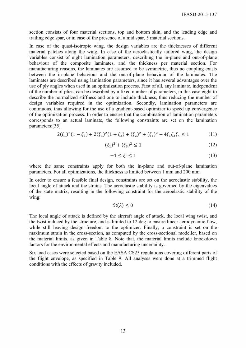
Tank ID Max. fuel mass Spanwise location
1 17000 kg 2.79 – 9.37 m
2 7500 kg 9.37 – 15.46 m
3 3000 kg 15.46 – 20.69 m
4 1500 kg 20.69 – 25.87 m
5 500 kg 25.87 – 29.00 m
Table 7: Fuel mass distribution
6.1 Optimization approach
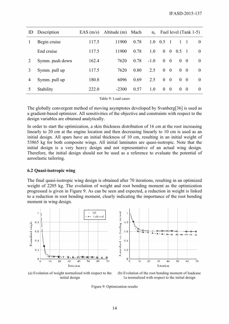
In order to assess the potential of aeroelastic tailoring, two optimizations are run: one, a thickness optimization of a quasi-isotropic wing to serve as a reference solution, and two, a complete thickness and stiffness optimization of a wing to show the effect of stiffness optimization on wing design. Table 8 shows the material properties used throughout the optimization.
𝐸!! 83.0 GPa
𝐸!! 8.5 GPa
𝐺!" 4.2 GPa
𝜈!" 0.35
𝜌 1452 kg/m3
𝜖!"# 4500 µstrain
𝛾!"# 7000 µstrain
Table 8: Material properties
The objective of each of the optimizations is to minimize weight. The wing is split in 16 spanwise sections: one section covering the area between the wing root and the first kink, three equally spaced sections covering the area between the first and the second kink, and 12 equally spaced sections covering the area between the second kink and the wing tip. Each
IFASD-2015-137
13
section consists of four material sections, top and bottom skin, and the leading edge and trailing edge spar, or in case of the presence of a mid spar, 5 material sections. In case of the quasi-isotropic wing, the design variables are the thicknesses of different material patches along the wing. In case of the aeroelastically tailored wing, the design variables consist of eight lamination parameters, describing the in-plane and out-of-plane behaviour of the composite laminates, and the thickness per material section. For manufacturing reasons, the laminates are assumed to be symmetric, thus no coupling exists between the in-plane behaviour and the out-of-plane behaviour of the laminates. The laminates are described using lamination parameters, since it has several advantages over the use of ply angles when used in an optimization process. First of all, any laminate, independent of the number of plies, can be described by a fixed number of parameters, in this case eight to describe the normalized stiffness and one to include thickness, thus reducing the number of design variables required in the optimization. Secondly, lamination parameters are continuous, thus allowing for the use of a gradient-based optimizer to speed up convergence of the optimization process. In order to ensure that the combination of lamination parameters corresponds to an actual laminate, the following constraints are set on the lamination parameters:[35]
2 𝜉! ! 1− 𝜉! + 2 𝜉! ! 1+ 𝜉! + 𝜉! ! + 𝜉! ! − 4𝜉!𝜉!𝜉! ≤ 1 (11)
𝜉! ! + 𝜉! ! ≤ 1 (12)
−1 ≤ 𝜉! ≤ 1 (13)
where the same constraints apply for both the in-plane and out-of-plane lamination parameters. For all optimizations, the thickness is limited between 1 mm and 200 mm. In order to ensure a feasible final design, constraints are set on the aeroelastic stability, the local angle of attack and the strains. The aeroelastic stability is governed by the eigenvalues of the state matrix, resulting in the following constraint for the aeroelastic stability of the wing: ℜ 𝜆 ≤ 0 (14)
The local angle of attack is defined by the aircraft angle of attack, the local wing twist, and the twist induced by the structure, and is limited to 12 deg to ensure linear aerodynamic flow, while still leaving design freedom to the optimizer. Finally, a constraint is set on the maximum strain in the cross-section, as computed by the cross-sectional modeller, based on the material limits, as given in Table 8. Note that, the material limits include knockdown factors for the environmental effects and manufacturing uncertainty.
Six load cases were selected based on the EASA CS25 regulations covering different parts of the flight envelope, as specified in Table 9. All analyses were done at a trimmed flight conditions with the effects of gravity included.
IFASD-2015-137
14
ID Description EAS (m/s) Altitude (m) Mach nz Fuel level (Tank 1-5)
1 Begin cruise 117.5 11900 0.78 1.0 0.5 1 1 1 0
End cruise 117.5 11900 0.78 1.0 0 0 0.5 1 0
2 Symm. push down 162.4 7620 0.78 -1.0 0 0 0 0 0
3 Symm. pull up 117.5 7620 0.80 2.5 0 0 0 0 0
4 Symm. pull up 180.8 6096 0.69 2.5 0 0 0 0 0
5 Stability 222.0 -2300 0.57 1.0 0 0 0 0 0
Table 9: Load cases
The globally convergent method of moving asymptotes developed by Svanberg[36] is used as a gradient-based optimizer. All sensitivities of the objective and constraints with respect to the design variables are obtained analytically.
In order to start the optimization, a skin thickness distribution of 16 cm at the root increasing linearly to 20 cm at the engine location and then decreasing linearly to 10 cm is used as an initial design. All spars have an initial thickness of 10 cm, resulting in an initial weight of 53865 kg for both composite wings. All initial laminates are quasi-isotropic. Note that the initial design is a very heavy design and not representative of an actual wing design. Therefore, the initial design should not be used as a reference to evaluate the potential of aeroelastic tailoring.
6.2 Quasi-isotropic wing
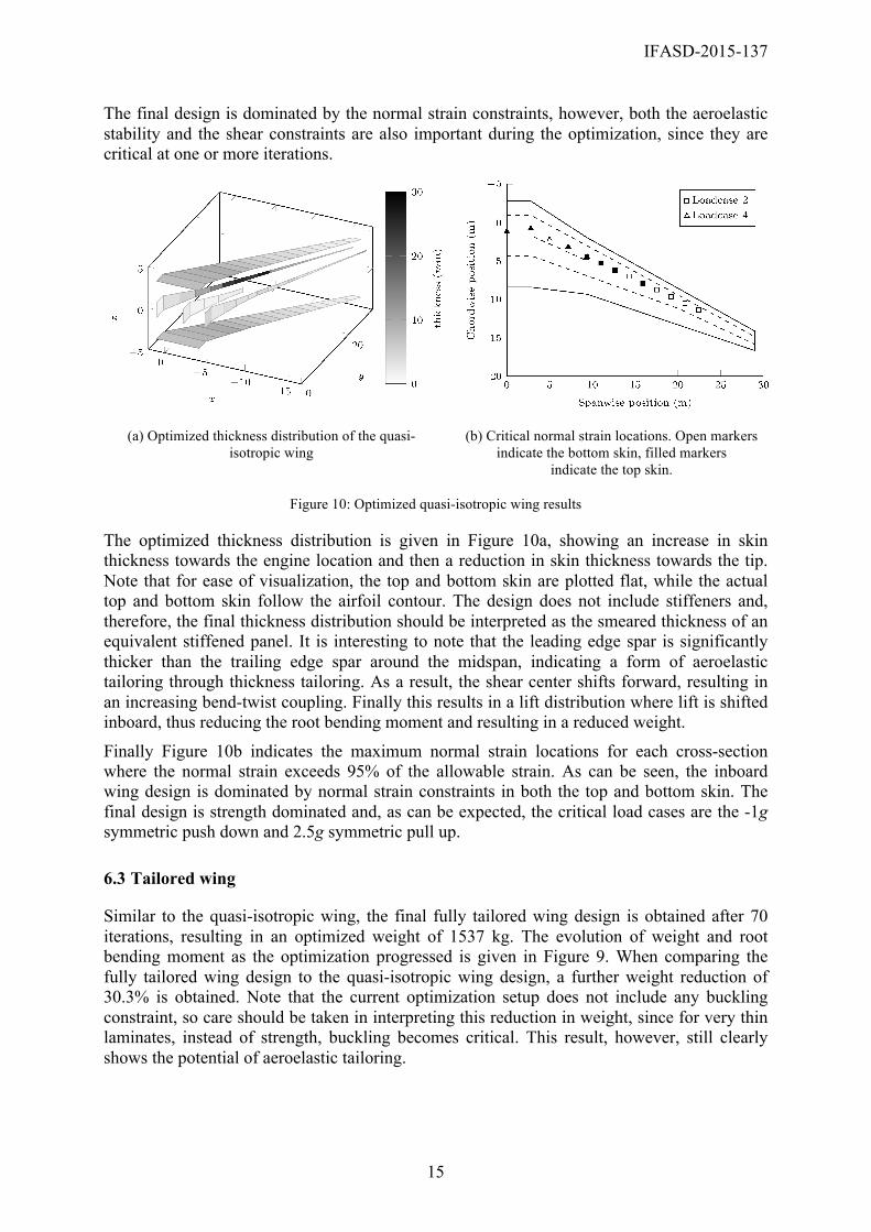
The final quasi-isotropic wing design is obtained after 70 iterations, resulting in an optimized weight of 2205 kg. The evolution of weight and root bending moment as the optimization progressed is given in Figure 9. As can be seen and expected, a reduction in weight is linked to a reduction in root bending moment, clearly indicating the importance of the root bending moment in wing design.
(a) Evolution of weight normalized with respect to the
initial design (b) Evolution of the root bending moment of loadcase
1a normalized with respect to the initial design
Figure 9: Optimization results
IFASD-2015-137
15
The final design is dominated by the normal strain constraints, however, both the aeroelastic stability and the shear constraints are also important during the optimization, since they are critical at one or more iterations.
(a) Optimized thickness distribution of the quasi-
isotropic wing (b) Critical normal strain locations. Open markers
indicate the bottom skin, filled markers indicate the top skin.
Figure 10: Optimized quasi-isotropic wing results
The optimized thickness distribution is given in Figure 10a, showing an increase in skin thickness towards the engine location and then a reduction in skin thickness towards the tip. Note that for ease of visualization, the top and bottom skin are plotted flat, while the actual top and bottom skin follow the airfoil contour. The design does not include stiffeners and, therefore, the final thickness distribution should be interpreted as the smeared thickness of an equivalent stiffened panel. It is interesting to note that the leading edge spar is significantly thicker than the trailing edge spar around the midspan, indicating a form of aeroelastic tailoring through thickness tailoring. As a result, the shear center shifts forward, resulting in an increasing bend-twist coupling. Finally this results in a lift distribution where lift is shifted inboard, thus reducing the root bending moment and resulting in a reduced weight.
Finally Figure 10b indicates the maximum normal strain locations for each cross-section where the normal strain exceeds 95% of the allowable strain. As can be seen, the inboard wing design is dominated by normal strain constraints in both the top and bottom skin. The final design is strength dominated and, as can be expected, the critical load cases are the -1g symmetric push down and 2.5g symmetric pull up.
6.3 Tailored wing
Similar to the quasi-isotropic wing, the final fully tailored wing design is obtained after 70 iterations, resulting in an optimized weight of 1537 kg. The evolution of weight and root bending moment as the optimization progressed is given in Figure 9. When comparing the fully tailored wing design to the quasi-isotropic wing design, a further weight reduction of 30.3% is obtained. Note that the current optimization setup does not include any buckling constraint, so care should be taken in interpreting this reduction in weight, since for very thin laminates, instead of strength, buckling becomes critical. This result, however, still clearly shows the potential of aeroelastic tailoring.
IFASD-2015-137
16
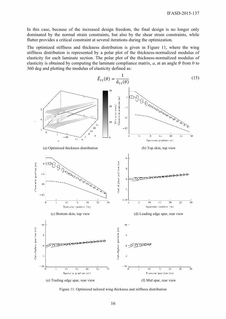
In this case, because of the increased design freedom, the final design is no longer only dominated by the normal strain constraints, but also by the shear strain constraints, while flutter provides a critical constraint at several iterations during the optimization.
The optimized stiffness and thickness distribution is given in Figure 11, where the wing stiffness distribution is represented by a polar plot of the thickness-normalized modulus of elasticity for each laminate section. The polar plot of the thickness-normalized modulus of elasticity is obtained by computing the laminate compliance matrix, a, at an angle 𝜃 from 0 to 360 deg and plotting the modulus of elasticity defined as:
𝐸!! 𝜃 =1
𝑎!! 𝜃 (15)
(a) Optimized thickness distribution (b) Top skin, top view
(c) Bottom skin, top view (d) Leading edge spar, rear view
(e) Trailing edge spar, rear view (f) Mid spar, rear view
Figure 11: Optimized tailored wing thickness and stiffness distribution
IFASD-2015-137
17
Four spanwise sections can be identified when looking at the skin stiffness distribution: one, from the root upto the engine location, two, from the engine location upto around 13 m span, three, up to around 23 m span, and four, up to the wing tip. The first section up to the engine introduces a bend-twist coupling of the inboard section to produce less wash-out in the wing root section. This allows for a reduced skin thickness when compared to the quasi-isotropic wing, while still providing sufficient stiffness to provide a twist distribution that generates sufficient lift. The second section is dominated by stiffness along the wing axis to provide sufficient stiffness to sustain all loads. Most classic aeroelastic tailoring can be seen in the third section, where the laminates introduce a bend-twist coupling to produce wing wash-out and thus shift the lift inboard. Finally, the fourth section is the tip region, where the stiffness distribution has little influence on the overall wing design and the laminates are still close to the initial quasi-isotropic laminates. When looking at the wing spars, it can be seen that little tailoring is present except for some tailoring in the wing root.
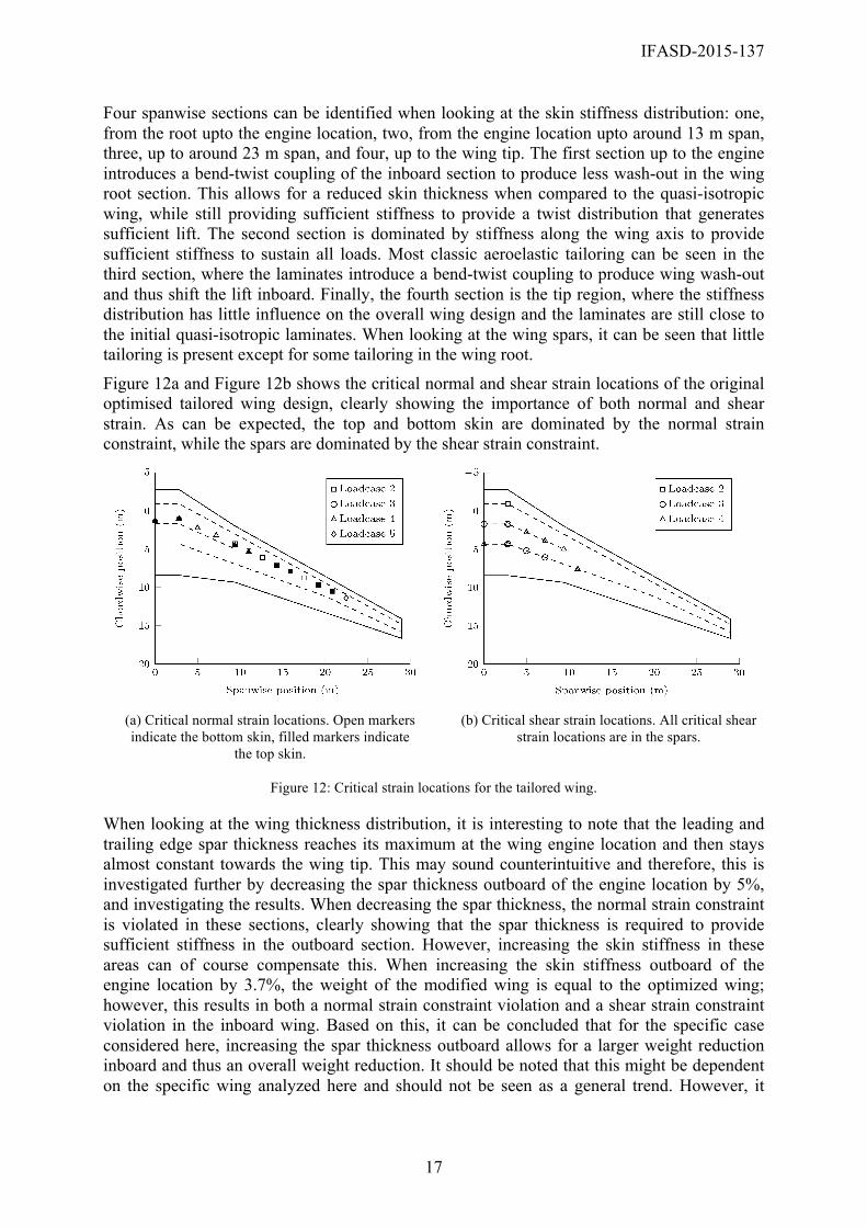
Figure 12a and Figure 12b shows the critical normal and shear strain locations of the original optimised tailored wing design, clearly showing the importance of both normal and shear strain. As can be expected, the top and bottom skin are dominated by the normal strain constraint, while the spars are dominated by the shear strain constraint.
(a) Critical normal strain locations. Open markers indicate the bottom skin, filled markers indicate
the top skin.
(b) Critical shear strain locations. All critical shear strain locations are in the spars.
Figure 12: Critical strain locations for the tailored wing.
When looking at the wing thickness distribution, it is interesting to note that the leading and trailing edge spar thickness reaches its maximum at the wing engine location and then stays almost constant towards the wing tip. This may sound counterintuitive and therefore, this is investigated further by decreasing the spar thickness outboard of the engine location by 5%, and investigating the results. When decreasing the spar thickness, the normal strain constraint is violated in these sections, clearly showing that the spar thickness is required to provide sufficient stiffness in the outboard section. However, increasing the skin stiffness in these areas can of course compensate this. When increasing the skin stiffness outboard of the engine location by 3.7%, the weight of the modified wing is equal to the optimized wing; however, this results in both a normal strain constraint violation and a shear strain constraint violation in the inboard wing. Based on this, it can be concluded that for the specific case considered here, increasing the spar thickness outboard allows for a larger weight reduction inboard and thus an overall weight reduction. It should be noted that this might be dependent on the specific wing analyzed here and should not be seen as a general trend. However, it
IFASD-2015-137
18
clearly shows that in case of stiffness and thickness tailoring everything is coupled and therefore the final design might not necessarily be intuitive. When looking at the critical load cases, it can be concluded, that the wing design is no longer only dominated the -1g symmetric push down and 2.5g symmetric pull up, but also the load case on the stability boundary influences the final design.
In conclusion, although care should be taken when interpreting the results, since buckling is not included as a constraint and aerodynamic performance might impose a constraint on the wing lift distribution, the final optimized tailored wing, clearly shows the potential of aeroelastic tailoring and the power of the framework described in the present paper.
7 CONCLUSIONS
A dynamic aeroelastic framework for the conceptual design of a generic composite wing structure is presented. The wing is discretized in several spanwise sections, where each section has a number of laminates throughout the cross-section, each having their own stiffness and thickness. The laminates are described using lamination parameters to allow for the use of a gradient-based optimizer.
The framework has been applied to the optimization of a generic wing designed for large civilian aircraft. Two optimizations were run: one, a quasi-isotropic wing where only thickness is optimized to act as a reference solution, and two, a fully tailored wing. Aeroelastic stability and maximum strain were applied as constraints. The results clearly show the advantage of using aeroelastic tailoring to improve the performance of aircraft wings. Four spanwise sections can be identified when looking at the stiffness distribution of the final wing, where the third section spanning midspan to around 80% of the span appears to be most important for aeroelastic tailoring.
Future work will focus on the introduction of a buckling constraint and the investigation of aeroelastic tailoring under gust loads.
In conclusion, the final optimized tailored wing clearly shows the potential of aeroelastic tailoring and the power of the framework described in the present paper.
8 REFERENCES
[1] M. H. Shirk, T. J. Hertz, and T. A. Weisshaar, “Aeroelastic Tailoring Theory, Practice, and Promise,” J Aircraft, vol. 23, no. 1, pp. 6–18, Jan. 1986.
[2] T. J. Hertz, M. H. Shirk, R. H. Ricketts, and T. A. Weisshaar, “Aeroelastic tailoring with composites applied to forward swept wings,” DTIC Document, AFWAL-TR-81-3043, 1981.
[3] F. E. Eastep, V. A. Tischler, V. B. Venkayya, and N. S. Khot, “Aeroelastic Tailoring of Composite Structures,” Journal of Aircraft, vol. 36, no. 6, pp. 1041–1047, 1999.
[4] M. Kameyama and H. Fukunaga, “Optimum design of composite plate wings for aeroelastic characteristics using lamination parameters,” Comput Struct, vol. 85, no. 3–4, pp. 213–224, Feb. 2007.
[5] S. Guo, “Aeroelastic optimization of an aerobatic aircraft wing structure,” Aerosp Sci Technol, vol. 11, no. 5, pp. 396–404, Jun. 2007.
[6] C. L. Pettit and R. V. Grandhi, “Optimization of a wing structure for gust response and aileron effectiveness,” J Aircraft, vol. 40, no. 6, pp. 1185–1191, Nov. 2003.
IFASD-2015-137
19
[7] T. U. Kim and I. H. Hwang, “Optimal design of composite wing subjected to gust loads,” Comput Struct, vol. 83, no. 19–20, pp. 1546–1554, Jul. 2005.
[8] G. A. Georghiades, S. J. Guo, and J. R. Banerjee, “Flutter characteristics of laminated composite wings,” Journal of Aircraft, vol. 33, no. 6, pp. 1204–1206, 1996.
[9] S. J. Guo, J. R. Bannerjee, and C. W. Cheung, “The effect of laminate lay-up on the flutter speed of composite wings,” P I Mech Eng G-J Aer, vol. 217, no. G3, pp. 115–122, 2003.
[10] T. A. Weisshaar and D. K. Duke, “Induced drag reduction using aeroelastic tailoring with adaptive control surfaces,” J Aircraft, vol. 43, no. 1, pp. 157–164, Jan. 2006.
[11] Z. M. Qin, L. Librescu, and P. Marzocca, “Aeroelasticity of composite aerovehicle wings in supersonic flows,” J Spacecraft Rockets, vol. 40, no. 2, pp. 162–173, Mar. 2003.
[12] F. H. Gern and L. Librescu, “Aeroelastic tailoring of composite wings exhibiting nonclassical effects and carrying external stores,” J Aircraft, vol. 37, no. 6, pp. 1097–1104, Nov. 2000.
[13] G. A. A. Thuwis, R. Breuker, M. M. Abdalla, and Z. Gürdal, “Aeroelastic tailoring using lamination parameters,” Structural and Multidisciplinary Optimization, vol. 41, no. 4, pp. 637–646, 2009.
[14] L. Librescu and A. A. Khdeir, “Aeroelastic divergence of swept-forward composite wings including warping restraint effect,” AIAA Journal, vol. 26, no. 11, pp. 1373–1377, 1988.
[15] L. Librescu and J. Simovich, “General formulation for the aeroelastic divergence of composite swept-forward wing structures,” Journal of Aircraft, vol. 25, no. 4, pp. 364–371, 1988.
[16] L. Librescu and O. Song, “On the static aeroelastic tailoring of composite aircraft swept wings modelled as thin-walled beam structures,” Composite Engineering, vol. 2, no. 5–7, pp. 497–512, 1992.
[17] Z. Qin, P. Marzocca, and L. Librescu, “Aeroelastic instability and response of advanced aircraft wings at subsonic flight speeds,” Aerospace Science and Technology, vol. 6, pp. 195–208, 2002.
[18] J. K. S. Dillinger, T. Klimmek, M. M. Abdalla, and Z. Gürdal, “Stiffness Optimization of Composite Wings with Aeroelastic Constraints,” Journal of Aircraft, vol. 50, no. 4, pp. 1159–1168, 2013.
[19] O. Stodieck, J. E. Cooper, P. M. Weaver, and P. Kealy, “Improved aeroelastic tailoring using tow-steered composites,” Compos Struct, vol. 106, pp. 703–715, Dec. 2013.
[20] B. K. Stanford, C. V. Jutte, and K. Chauncey Wu, “Aeroelastic benefits of tow steering for composite plates,” Composite Structures, vol. 118, pp. 416–422, Dec. 2014.
[21] H. Arizono and K. Isogai, “Application of genetic algorithm for aeroelastic tailoring of a cranked-arrow wing,” J Aircraft, vol. 42, no. 2, pp. 493–499, Mar. 2005.
[22] S. J. Guo, W. Y. Cheng, and D. G. Cui, “Aeroelastic tailoring of composite wing structures by laminate layup optimization,” Aiaa J, vol. 44, no. 12, pp. 3146–3150, Dec. 2006.
[23] A. Manan, G. A. Vio, M. Y. Harmin, and J. E. Cooper, “Optimization of aeroelastic composite structures using evolutionary algorithms,” Eng Optimiz, vol. 42, no. 2, pp. 171–184, 2010.
[24] E. Ferede and M. Abdalla, “Cross-sectional modelling of thin-walled composite beams,” presented at the 55th AIAA/ASME/ASCE/AHS/SC Structures, Structural Dynamics, and Materials Conference, 2014.
IFASD-2015-137
20
[25] R. De Breuker, M. M. Abdalla, and Z. Gurdal, “A Generic Morphing Wing Analysis and Design Framework,” Journal of Intelligent Material Systems and Structures, vol. 22, no. 10, pp. 1025–1039, 2011.
[26] J. Weissinger, “The lift distribution of swept-back wings,” NACA-TM-1120, 1947. [27] J.-M. Battini and C. Pacoste, “Co-rotational beam elements with warping effects in
instability problems,” Computer Methods in Applied Mechanics and Engineering, vol. 191, no. 17–18, pp. 1755–1789, Feb. 2002.
[28] K.-J. Bathe and S. Bolourchi, “Large displacement analysis of three-dimensional beam structures,” International Journal for Numerical Methods in Engineering, vol. 14, no. 7, pp. 961–986, 1979.
[29] J. Katz and A. Plotkin, Low-Speed Aerodynamics. Cambridge: Cambridge University Press, 2001.
[30] J. Murua, R. Palacios, and J. M. R. Graham, “Assessment of Wake-Tail Interference Effects on the Dynamics of Flexible Aircraft,” AIAA Journal, vol. 50, no. 7, pp. 1575–1585, 2012.
[31] N. P. M. Werter, R. De Breuker, and M. M. Abdalla, “Continuous-time state-space unsteady aerodynamic modelling for efficient aeroelastic load analysis,” presented at the International Forum on Aeroelasticity and Structural Dynamics, 2015.
[32] M. J. Patil and D. H. Hodges, “On the importance of aerodynamic and structural geometrical nonlinearities in aeroelastic behavior of high-aspect-ratio wings,” Journal of Fluids and Structures, vol. 19, no. 7, pp. 905–915, Aug. 2004.
[33] H. L. Runyan and J. L. Sewall, “Experimental Investigation of the Effects of Concentrated Weights on Flutter Characteristics of a Straight Cantilever Wing,” Jun. 1948.
[34] S. A. Fazelzadeh, A. Mazidi, and H. Kalantari, “Bending-torsional flutter of wings with an attached mass subjected to a follower force,” Journal of Sound and Vibration, vol. 323, no. 1–2, pp. 148–162, Jun. 2009.
[35] V. B. Hammer, M. P. Bendsøe, R. Lipton, and P. Pedersen, “Parametrization in laminate design for optimal compliance,” International Journal of Solids and Structures, vol. 34, no. 4, pp. 415–434, 1997.
[36] Svanberg, “A class of globally convergent optimization methods based on conservative convex separable approximations,” SIAM Journal on Optimization, vol. 12, no. 2, pp. 555–573, 2002.
COPYRIGHT STATEMENT
The authors confirm that they, and/or their company or organization, hold copyright on all of the original material included in this paper. The authors also confirm that they have obtained permission, from the copyright holder of any third party material included in this paper, to publish it as part of their paper. The authors confirm that they give permission, or have obtained permission from the copyright holder of this paper, for the publication and distribution of this paper as part of the IFASD 2015 proceedings or as individual off-prints from the proceedings.