Embed Size (px)
Citation preview
© buildingSMART Infra Room page 1
IFC-Bridge Fast Track Project
Report WP1: Requirements analysis
Status: DRAFT
Date: 2018-04-10
Christophe Castaing (Project Lead), André Borrmann (Technical Lead),
Pierre Benning, Claude Dumoulin, Tim Chipman, Juha Hyvärinen, Thomas Liebich, Stefan
Markič, Laura Mol, Sergej Muhič, Hyounseok Moon, Heikki Myllymaki, Ning Suo, Shufeng
Song, Ai Shanding, Liu Siming, Zhang Yi, Nobuyoshi Yabuki, Feifei Zhao

© buildingSMART Infra Room page 2
1 Overview and methodology The IFC-Bridge project aims at extending the IFC data model in order to allow the precise
description of the semantics and geometry of bridges. It was initiated by the bSI Infra Room
as a fast track project with a project duration of two years.
WP1 was intended to define the scope of the project and the requirements of the IFC-Bridge
extension. Given the restricted project duration, it was necessary to focus on common and
widespread bridge types and to include only those use cases that provide a high value to the
end users and require reasonable efforts for defining and validating the necessary IFC
extensions.
As a basis for defining the IFC-Bridge extensions, the international project team identified the
most important uses cases of the data exchange processes in infrastructure projects. The
point of departure for this process had been provided by the outcomes of the IFC-Infra overall
architecture process.
The defined list of use cases is not intended to be exhaustive. Instead, the most important use
cases have been selected from interviews with experts having practical experience in bridge
projects. In addition, the input from several national initiatives was taken into account:
• China: CRBIM project
• France: MINnD project
• Germany: IFC-Bridge Expert Group
• Nordic Chapter: IFC-Bridge Expert Group
• USA: FHWA project
From the identified use cases, the basic requirements for the IFC-Bridge have been derived
focusing on geometry representations and semantical descriptions. They have been distilled
into three proposed Model View Definitions (MVDs) which are going to be developed
throughout the project.
© buildingSMART Infra Room page 3
2 Bridge types covered The following bridge types (structural system) have been identified as the most common and
widespread ones across the world. They are thus considered to be in-scope of this project.
The developed IFC-Bridge extensions will be validated using examples of theses bridge
types.
• Slab Bridge
• Girder Bridge
o Slab-Girder Bridge
o Box-girder bridge
• Frame Bridge
• Rigid Frame Bridge
• Culvert
The following bridges types are expected to be covered by IFC and the IFC-Bridge extension
as well, however, they will not be subject to validation tests:
• Truss bridge
• Arch bridge
• Cantilever bridge
• Cable-stayed bridge
• Suspension bridge
From a material viewpoint, the following bridge types are covered:
• Reinforced Concrete bridges
• Prestressed Concrete bridges
• Steel/Concrete Composite bridges
• Steel girder bridges
• Steel bridges
Particular emphasis will be placed on realizing the necessary data structures for modeling
pre-stressing systems.
© buildingSMART Infra Room page 4
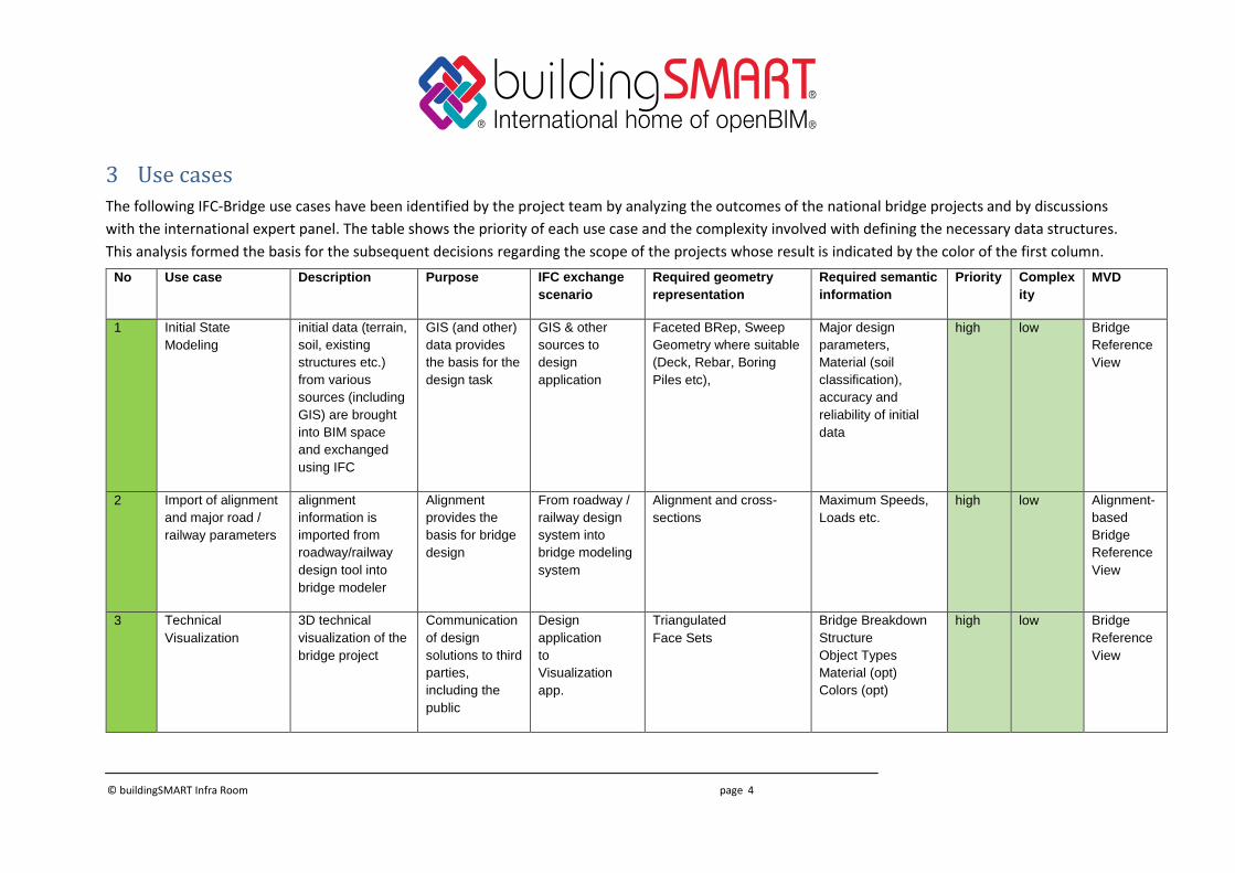
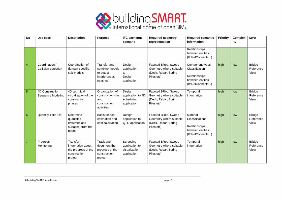
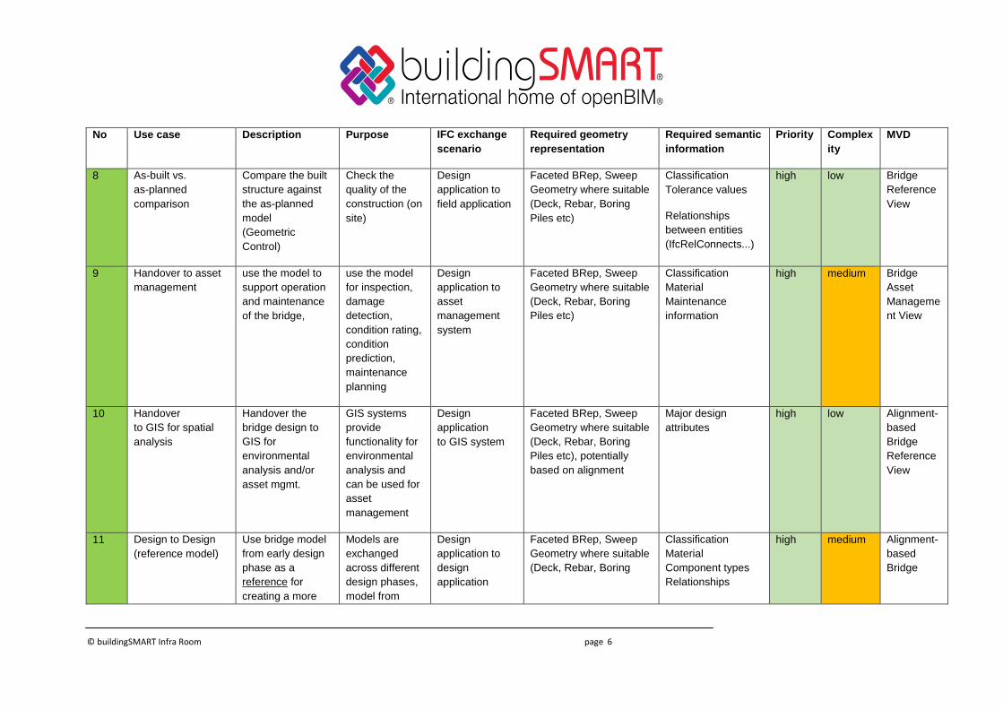
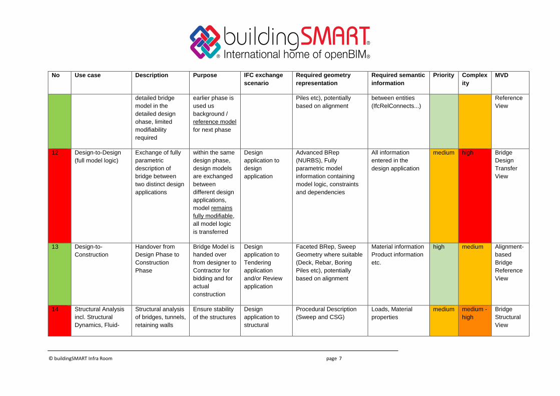
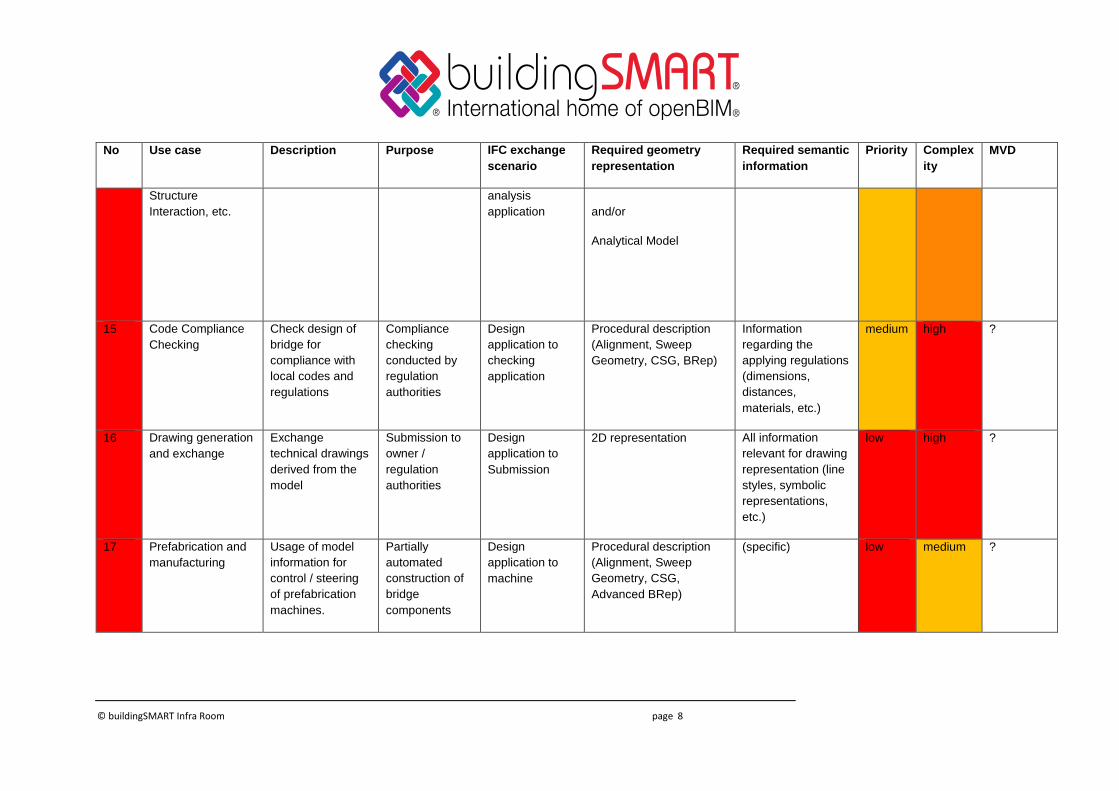
3 Use cases The following IFC-Bridge use cases have been identified by the project team by analyzing the outcomes of the national bridge projects and by discussions
with the international expert panel. The table shows the priority of each use case and the complexity involved with defining the necessary data structures.
This analysis formed the basis for the subsequent decisions regarding the scope of the projects whose result is indicated by the color of the first column.
No Use case Description Purpose IFC exchange
scenario
Required geometry
representation
Required semantic
information
Priority
Complex
ity
MVD
1 Initial State
Modeling
initial data (terrain,
soil, existing
structures etc.)
from various
sources (including
GIS) are brought
into BIM space
and exchanged
using IFC
GIS (and other)
data provides
the basis for the
design task
GIS & other
sources to
design
application
Faceted BRep, Sweep
Geometry where suitable
(Deck, Rebar, Boring
Piles etc),
Major design
parameters,
Material (soil
classification),
accuracy and
reliability of initial
data
high low Bridge
Reference
View
2 Import of alignment
and major road /
railway parameters
alignment
information is
imported from
roadway/railway
design tool into
bridge modeler
Alignment
provides the
basis for bridge
design
From roadway /
railway design
system into
bridge modeling
system
Alignment and cross-
sections
Maximum Speeds,
Loads etc.
high low Alignment-
based
Bridge
Reference
View
3 Technical
Visualization
3D technical
visualization of the
bridge project
Communication
of design
solutions to third
parties,
including the
public
Design
application
to
Visualization
app.
Triangulated
Face Sets
Bridge Breakdown
Structure
Object Types
Material (opt)
Colors (opt)
high low Bridge
Reference
View
© buildingSMART Infra Room page 5
No Use case Description Purpose IFC exchange
scenario
Required geometry
representation
Required semantic
information
Priority
Complex
ity
MVD
Relationships
between entities
(IfcRelConnects...)
4 Coordination /
Collision detection
Coordination of
domain-specific
sub-models
Transfer and
combine models
to detect
interferences
(clashes)
Design
application
to
Design
application
Faceted BRep, Sweep
Geometry where suitable
(Deck, Rebar, Boring
Piles etc)
Component types
Classification
Relationships
between entities
(IfcRelConnects...)
high low Bridge
Reference
View
5 4D Construction
Sequence Modeling
4D technical
visualization of the
construction
phases
Organization of
construction site
and
construction
activities
Design
application to 4D
scheduling
application
Faceted BRep, Sweep
Geometry where suitable
(Deck, Rebar, Boring
Piles etc)
Temporal
information
high low Bridge
Reference
View
6 Quantity Take-Off Determine
quantities
(volumes and
surfaces) from the
model
Basis for cost
estimation and
cost calculation
Design
application to
QTO application
Faceted BRep, Sweep
Geometry where suitable
(Deck, Rebar, Boring
Piles etc)
Material,
Classifications
Relationships
between entities
(IfcRelConnects...)
high low Bridge
Reference
View
7 Progress
Monitoring
Transfer
information about
the progress of the
construction
project
Track and
document the
progress of the
construction
project
Surveying
application to
visualization
application
Faceted BRep, Sweep
Geometry where suitable
(Deck, Rebar, Boring
Piles etc)
Temporal
information
high low Bridge
Reference
View
© buildingSMART Infra Room page 6
No Use case Description Purpose IFC exchange
scenario
Required geometry
representation
Required semantic
information
Priority
Complex
ity
MVD
8 As-built vs.
as-planned
comparison
Compare the built
structure against
the as-planned
model
(Geometric
Control)
Check the
quality of the
construction (on
site)
Design
application to
field application
Faceted BRep, Sweep
Geometry where suitable
(Deck, Rebar, Boring
Piles etc)
Classification
Tolerance values
Relationships
between entities
(IfcRelConnects...)
high low Bridge
Reference
View
9 Handover to asset
management
use the model to
support operation
and maintenance
of the bridge,
use the model
for inspection,
damage
detection,
condition rating,
condition
prediction,
maintenance
planning
Design
application to
asset
management
system
Faceted BRep, Sweep
Geometry where suitable
(Deck, Rebar, Boring
Piles etc)
Classification
Material
Maintenance
information
high medium Bridge
Asset
Manageme
nt View
10 Handover
to GIS for spatial
analysis
Handover the
bridge design to
GIS for
environmental
analysis and/or
asset mgmt.
GIS systems
provide
functionality for
environmental
analysis and
can be used for
asset
management
Design
application
to GIS system
Faceted BRep, Sweep
Geometry where suitable
(Deck, Rebar, Boring
Piles etc), potentially
based on alignment
Major design
attributes
high low Alignment-
based
Bridge
Reference
View
11 Design to Design
(reference model)
Use bridge model
from early design
phase as a
reference for
creating a more
Models are
exchanged
across different
design phases,
model from
Design
application to
design
application
Faceted BRep, Sweep
Geometry where suitable
(Deck, Rebar, Boring
Classification
Material
Component types
Relationships
high medium Alignment-
based
Bridge
© buildingSMART Infra Room page 7
No Use case Description Purpose IFC exchange
scenario
Required geometry
representation
Required semantic
information
Priority
Complex
ity
MVD
detailed bridge
model in the
detailed design
ohase, limited
modifiability
required
earlier phase is
used us
background /
reference model
for next phase
Piles etc), potentially
based on alignment
between entities
(IfcRelConnects...)
Reference
View
12 Design-to-Design
(full model logic)
Exchange of fully
parametric
description of
bridge between
two distinct design
applications
within the same
design phase,
design models
are exchanged
between
different design
applications,
model remains
fully modifiable,
all model logic
is transferred
Design
application to
design
application
Advanced BRep
(NURBS), Fully
parametric model
information containing
model logic, constraints
and dependencies
All information
entered in the
design application
medium high Bridge
Design
Transfer
View
13 Design-to-
Construction
Handover from
Design Phase to
Construction
Phase
Bridge Model is
handed over
from designer to
Contractor for
bidding and for
actual
construction
Design
application to
Tendering
application
and/or Review
application
Faceted BRep, Sweep
Geometry where suitable
(Deck, Rebar, Boring
Piles etc), potentially
based on alignment
Material information
Product information
etc.
high medium Alignment-
based
Bridge
Reference
View
14 Structural Analysis
incl. Structural
Dynamics, Fluid-
Structural analysis
of bridges, tunnels,
retaining walls
Ensure stability
of the structures
Design
application to
structural
Procedural Description
(Sweep and CSG)
Loads, Material
properties
medium medium -
high
Bridge
Structural
View
© buildingSMART Infra Room page 8
No Use case Description Purpose IFC exchange
scenario
Required geometry
representation
Required semantic
information
Priority
Complex
ity
MVD
Structure
Interaction, etc.
analysis
application
and/or
Analytical Model
15 Code Compliance
Checking
Check design of
bridge for
compliance with
local codes and
regulations
Compliance
checking
conducted by
regulation
authorities
Design
application to
checking
application
Procedural description
(Alignment, Sweep
Geometry, CSG, BRep)
Information
regarding the
applying regulations
(dimensions,
distances,
materials, etc.)
medium high ?
16 Drawing generation
and exchange
Exchange
technical drawings
derived from the
model
Submission to
owner /
regulation
authorities
Design
application to
Submission
2D representation All information
relevant for drawing
representation (line
styles, symbolic
representations,
etc.)
low high ?
17 Prefabrication and
manufacturing
Usage of model
information for
control / steering
of prefabrication
machines.
Partially
automated
construction of
bridge
components
Design
application to
machine
Procedural description
(Alignment, Sweep
Geometry, CSG,
Advanced BRep)
(specific) low medium ?
© buildingSMART Infra Room page 9
4 In-scope / Out-of-scope decisions Based on a careful analysis of the benefits of the individual uses cases and the complexity
and effort involved with defining the necessary data structures, the project team decided to
prioritize the following use cases for explicit consideration when designing the IFC-Bridge
extension:
• Initial State Modeling
• Import of major road / railway parameters
• Technical Visualization
• Coordination / Collison Detection
• 4D Construction Sequence Modeling
• Quantity Take-Off
• Progress Monitoring
• As-built vs. as-planned comparison
• Handover to asset management
• Handover to GIS for spatial analysis
• Design to design (reference model)
• Design to Construction
Due to overly high complexity, the following use cases are out of scope of this fast-track
project:
• Design to Design (Full model logic)
• Structural analysis
• Code Compliance Checking
• Drawing generation and exchange
• Prefabrication and manufacturing
It is emphasized that the exclusion from the fast-track project does not mean that these use
cases cannot be covered by future extensions of IFC-Bridge.
It has to be noted in particular, that the full design-to-design use case which incorporates the
model’s design logic, is excluded here as it would require software vendors to adapt modeling
functionality, which is not deemed practical for reasons of competitive advantage,
compatibility, and cost/benefit. Currently, there is no well-defined industry need that would
justify this effort.
© buildingSMART Infra Room page 10
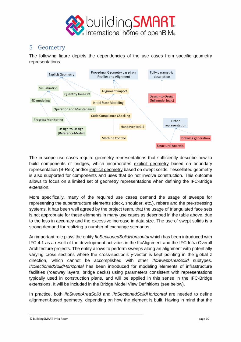
5 Geometry The following figure depicts the dependencies of the use cases from specific geometry
representations.
The in-scope use cases require geometry representations that sufficiently describe how to
build components of bridges, which incorporates explicit geometry based on boundary
representation (B-Rep) and/or implicit geometry based on swept solids. Tessellated geometry
is also supported for components and uses that do not involve construction. This outcome
allows to focus on a limited set of geometry representations when defining the IFC-Bridge
extension.
More specifically, many of the required use cases demand the usage of sweeps for
representing the superstructure elements (deck, shoulder, etc.), rebars and the pre-stressing
systems. It has been well agreed by the project team, that the usage of triangulated face sets
is not appropriate for these elements in many use cases as described in the table above, due
to the loss in accuracy and the excessive increase in data size. The use of swept solids is a
strong demand for realizing a number of exchange scenarios.
An important role plays the entity IfcSectionedSolidHorizontal which has been introduced with
IFC 4.1 as a result of the development activities in the IfcAlignment and the IFC Infra Overall
Architecture projects. The entity allows to perform sweeps along an alignment with potentially
varying cross sections where the cross-section’s y-vector is kept pointing in the global z
direction, which cannot be accomplished with other IfcSweptAreaSolid subtypes.
IfcSectionedSolidHorizontal has been introduced for modeling elements of infrastructure
facilities (roadway layers, bridge decks) using parameters consistent with representations
typically used in construction plans, and will be applied in this sense in the IFC-Bridge
extensions. It will be included in the Bridge Model View Definitions (see below).
In practice, both IfcSweptAreaSolid and IfcSectionedSolidHorizontal are needed to define
alignment-based geometry, depending on how the element is built. Having in mind that the
© buildingSMART Infra Room page 11
global z direction can be easily defined on site, it is used in case of casting in place. But if the
element is precast in a plant in a horizontal formwork, it is required to use a profile
perpendicular to the sweeping path.
6 Requirements resulting from Asset Management The Infra Room of buildingSMART International has conducted a project on Infrastructure
Asset Managers BIM Requirements. The results have been published in report TR1010 which
is available on the bSI website1.
The IFC-Bridge project team took the outcomes into consideration when defining the
requirements for the IFC-Bridge extension. The following table lists the individual requirements
and how the IFC-Bridge extension is able to meet them.
Unique identification Each IFC-Bridge model will be able to carry a unique identifier represented by the attribute name of an IfcBridge entity.
Network, geospatial, linear location IFC provides capabilities for geospatial referencing, a local coordinate system can be used for the BIM
model
IfcAlignment provides means for linear placement
Support for the network perspective has to be provided by IfcRoad and IfcRailways
Functional Requirement IfcBridge will provide attributes and properties for capturing functional requirements
Dimensions IFC-Bridge explicitly describes dimensions in terms such as height, width etc. explained in relation to respective object type.
System breakdown into Deck, Superstructure, Substructure
IFC-Bridge will provide a flexible spatial breakdown structure
Support of local/national/regional classification schemes
The IFC data model allows individual elements of a BIM model to be associated with any given classification (see Overall Architecture Report)
Support of local/national/regional Object Type Libraries
The IFC data model allows to connect any given Object Type Libraries with individual elements of a BIM model. To this end Linked Data approaches can be applied (see Overall Architecture Report).
Support of local/national/regional or project-specific property sets
The IFC data model allows to add user-defined property sets in an flexible manner.
Simple 3D geometry for Bridge Asset Management The Bridge Asset Management Handover MVD will demand explicit geometry (excluding NURBS) allowing primarily visualization and management.
1 https://buildingsmart-1xbd3ajdayi.netdna-ssl.com/wp-content/uploads/2018/01/18-01-09-AM-TR1010.pdf

© buildingSMART Infra Room page 12
Support of inspection activities The IFC-Bridge extension will support adding photographs and inspection results to individual components of a bridge model.
Support of sensor data The IFC model allows to represent sensors and integrate their values by referring to external data sets.
© buildingSMART Infra Room page 13
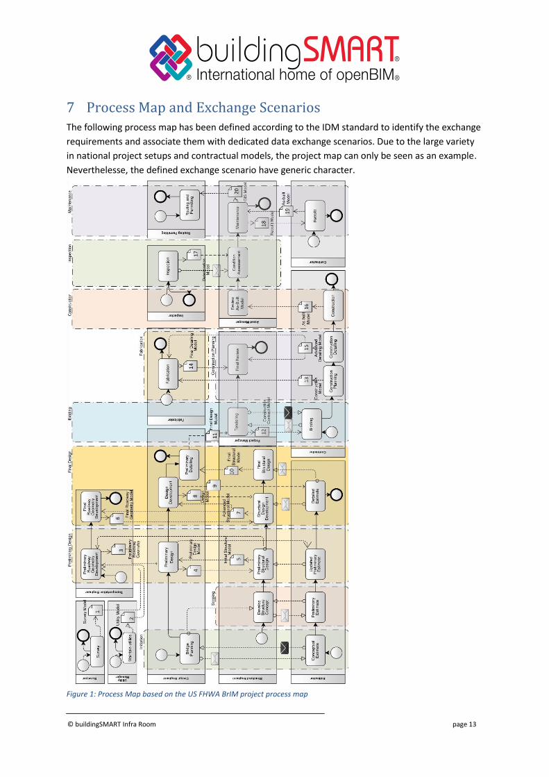
7 Process Map and Exchange Scenarios The following process map has been defined according to the IDM standard to identify the exchange
requirements and associate them with dedicated data exchange scenarios. Due to the large variety
in national project setups and contractual models, the project map can only be seen as an example.
Neverthelesse, the defined exchange scenario have generic character.
Figure 1: Process Map based on the US FHWA BrIM project process map
© buildingSMART Infra Room page 14
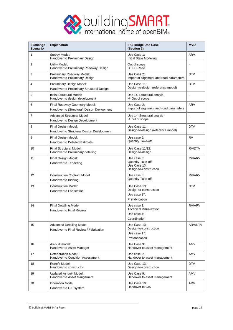
Exchange Scenario
Explanation IFC-Bridge Use Case (Section 3)
MVD
1 Survey Model: Handover to Preliminary Design
Use Case 1: Initial State Modeling
ARV
2 Utility Model: Handover to Preliminary Roadway Design
Out of scope IFC-Road
-
3 Preliminary Roadway Model: Handover to Preliminary Design
Use Case 2: Import of alignment and road parameters
DTV
4 Preliminary Design Model:
Handover to Preliminary Structural Design
Use Case 11: Design-to-design (reference model)
DTV
5 Initial Structural Model: Handover to design development
Use 14: Structural analyis Out of scope
-
6 Final Roadway Geometry Model:
Handover to (Structural) Deisgn Devlopment
Use Case 2: Import of alignment and road parameters
ARV
7 Advanced Structural Model:
Handover to Design Development
Use 14: Structural analyis out of scope
-
8 Final Design Model:
Handover to Structural Design Development
Use Case 11: Design-to-design (reference model)
DTV
9 Final Design Model:
Handover to Detailed Estimate
Use case 6: Quantity Take-off
RV
10 Final Structural Model: Handover to Preliminary detailing
Use Case 11/12: Design-to-design
RV/DTV
11 Final Design Model:
Handover to Tendering
Use case 6: Quantity Take-off Use Case 13: Design-to-construction
RV/ARV
12 Construction Contract Model
Handover to Bidding
Use case 6: Quantity Take-off
RV/ARV
13 Construction Model:
Handover to Fabrication
Use Case 13: Design-to-construction
Use case 17:
Prefabrication
DTV
14 Final Detailing Model
Handover to Final Review
Use case 3: Technical Vizualization
Use case 4:
Coordination
RV/ARV
15 Advanced Detailing Model:
Handover to Final Review / Fabrication
Use Case 13: Design-to-construction
Use case 17:
Prefabrication
ARV/DTV
16 As-built model: Handover to Asset Manager
Use Case 9: Handover to asset management
AMV
17 Deterioration Model: Handover to Condition Assessment
Use case 9: Handover to asset management
AMV
18 Retrofit Model: Handover to constructor
Use Case 13: Design-to-construction
DTV
19 Updated As-built Model: Handover to Asset Mangement
Use Case 9: Handover to asset management
AMV
20 Operation Model
Handover to GIS system
Use Case 10: Handover to GIS
ARV
© buildingSMART Infra Room page 15
8 Model View Definitions In order to reduce the complexity of the data model developments, it was decided to map the
use cases to the following basic Model View Definitions.
• Bridge Reference View (Bridge RV)
• Alignment-based Bridge Reference View (Bridge ARV)
• Bridge Design Transfer View (Bridge DTV)
• Bridge Asset Management Handover View (Bridge AMV)
The decision was taken to align both the Bridge Reference View and the Bridge Design
Transfer View with the existing views in IFC4, but extend them where necessary to capture
the specifics of bridges.
Fehler! Verweisquelle konnte nicht gefunden werden. lists the differences in terms of the
geometry representations supported between the IFC4 Reference view (IFC4 RV), the IFC4
Design Transfer View (IFC4 DTV., the Bridge Reference View (Bridge RV), the Bridge
Alignment-based Reference View (Bridge ARV) and the Bridge Design Transfer View
(Bridge DTV).
The basic differentiation between RV and DTV is also applied to the Bridge MVDs. Most
importantly, IfcCSGSolid (Constructive Solid Geometry = Boolean Operations on Solids) is
not supported by the Bridge RV, but by the Bridge DTV. Another important difference lies in
the support of IfcFacetedBrep and IfcAdvancedBrep which is only realized in Bridge DTV.
For representing BRep geometry in RV, the IfcPolygonalFaceSet representation must be
used. Curved surfaces (NURBS) are not supported by RV.
In addition, there will be the Alignment-based Reference View (Bridge ARV) which extends
the IFC4 Reference View by the support for IfcAlignment and IfcSectionedSolidHorizontal for
positioning and geometry creation. The reason for introducing the additional MVD lies in the
importance of alignment for linear infrastructure. As however, standard IFC viewers (which
typically do not support alignment) should be able to visualize bridge models, the basic
Bridge RV will not demand IfcAlignment to be supported, but rely instead on explicit
geometry and on Cartesian coordinates for positioning.
Other differences between Bridge RV, Bridge ARV and Bridge DTV may lie in further
geometric and semantic aspects and will be elaborated in the next phases of the project.
Also details of the Bridge Asset Management Handover View are to be decided in the
upcoming phases of the project.
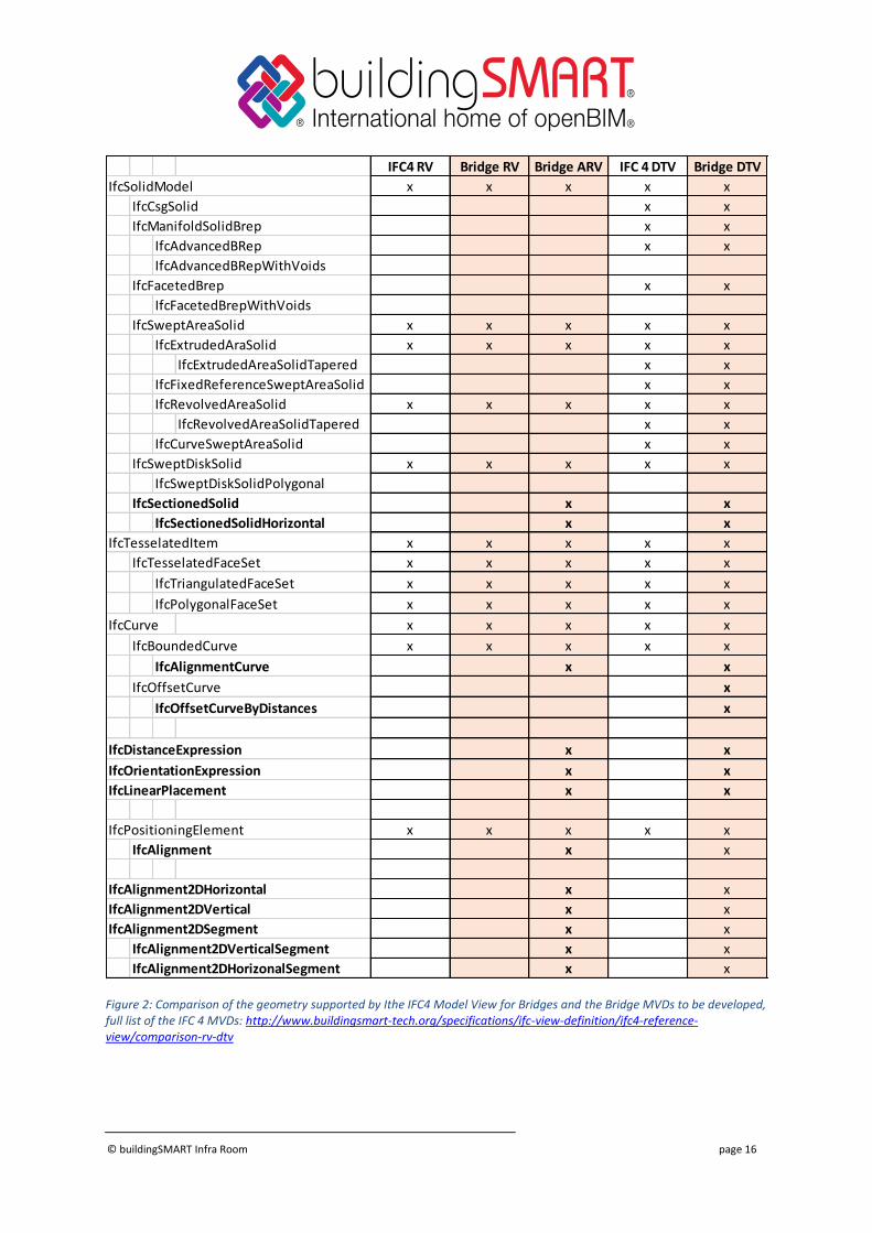
© buildingSMART Infra Room page 16
Figure 2: Comparison of the geometry supported by Ithe IFC4 Model View for Bridges and the Bridge MVDs to be developed, full list of the IFC 4 MVDs: http://www.buildingsmart-tech.org/specifications/ifc-view-definition/ifc4-reference-view/comparison-rv-dtv
IFC4 RV Bridge RV Bridge ARV IFC 4 DTV Bridge DTV
IfcSolidModel x x x x x
IfcCsgSolid x x
IfcManifoldSolidBrep x x
IfcAdvancedBRep x x
IfcAdvancedBRepWithVoids
IfcFacetedBrep x x
IfcFacetedBrepWithVoids
IfcSweptAreaSolid x x x x x
IfcExtrudedAraSolid x x x x x
IfcExtrudedAreaSolidTapered x x
IfcFixedReferenceSweptAreaSolid x x
IfcRevolvedAreaSolid x x x x x
IfcRevolvedAreaSolidTapered x x
IfcCurveSweptAreaSolid x x
IfcSweptDiskSolid x x x x x
IfcSweptDiskSolidPolygonal
IfcSectionedSolid x x
IfcSectionedSolidHorizontal x x
IfcTesselatedItem x x x x x
IfcTesselatedFaceSet x x x x x
IfcTriangulatedFaceSet x x x x x
IfcPolygonalFaceSet x x x x x
IfcCurve x x x x x
IfcBoundedCurve x x x x x
IfcAlignmentCurve x x
IfcOffsetCurve x
IfcOffsetCurveByDistances x
IfcDistanceExpression x x
IfcOrientationExpression x x
IfcLinearPlacement x x
IfcPositioningElement x x x x x
IfcAlignment x x
IfcAlignment2DHorizontal x x
IfcAlignment2DVertical x x
IfcAlignment2DSegment x x
IfcAlignment2DVerticalSegment x x
IfcAlignment2DHorizonalSegment x x
© buildingSMART Infra Room page 17
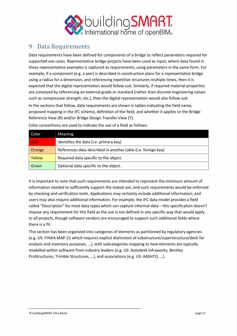
9 Data Requirements Data requirements have been defined for components of a bridge to reflect parameters required for
supported use cases. Representative bridge projects have been used as input, where data found in
these representative examples is captured as requirements, using parameters in the same form. For
example, if a component (e.g. a pier) is described in construction plans for a representative bridge
using a radius for a dimension, and referencing repetitive structures multiple times, then it is
expected that the digital representation would follow suit. Similarly, if required material properties
are conveyed by referencing an external grade or standard (rather than discrete engineering values
such as compressive strength, etc.), then the digital representation would also follow suit.
In the sections that follow, data requirements are shown in tables indicating the field name,
proposed mapping in the IFC schema, definition of the field, and whether it applies to the Bridge
Reference View (R) and/or Bridge Design Transfer View (T).
Color conventions are used to indicate the use of a field as follows:
Color Meaning
Red Identifies the data (i.e. primary key)
Orange References data described in another table (i.e. foreign key)
Yellow Required data specific to the object.
Green Optional data specific to the object.
It is important to note that such requirements are intended to represent the minimum amount of
information needed to sufficiently support the stated use, and such requirements would be enforced
by checking and verification tools. Applications may certainly include additional information, and
users may also require additional information. For example, the IFC data model provides a field
called “Description” for most data types which can capture informal data – this specification doesn’t
impose any requirement for this field as the use is not defined in any specific way that would apply
to all projects, though software vendors are encouraged to support such additional fields where
there is a fit.
This section has been organized into categories of elements as partitioned by regulatory agencies
(e.g. US: FHWA MAP-21 which requires explicit distinction of substructure/superstructure/deck for
analysis and inventory purposes, …), with subcategories mapping to how elements are typically
modelled within software from industry leaders (e.g. US: Autodesk Infraworks, Bentley
ProStructures, Trimble Structures, …), and associations (e.g. US: AASHTO, …).
© buildingSMART Infra Room page 18
9.1 General Conditions
This section refers to the overall context, positioning, and site conditions where a bridge is located.
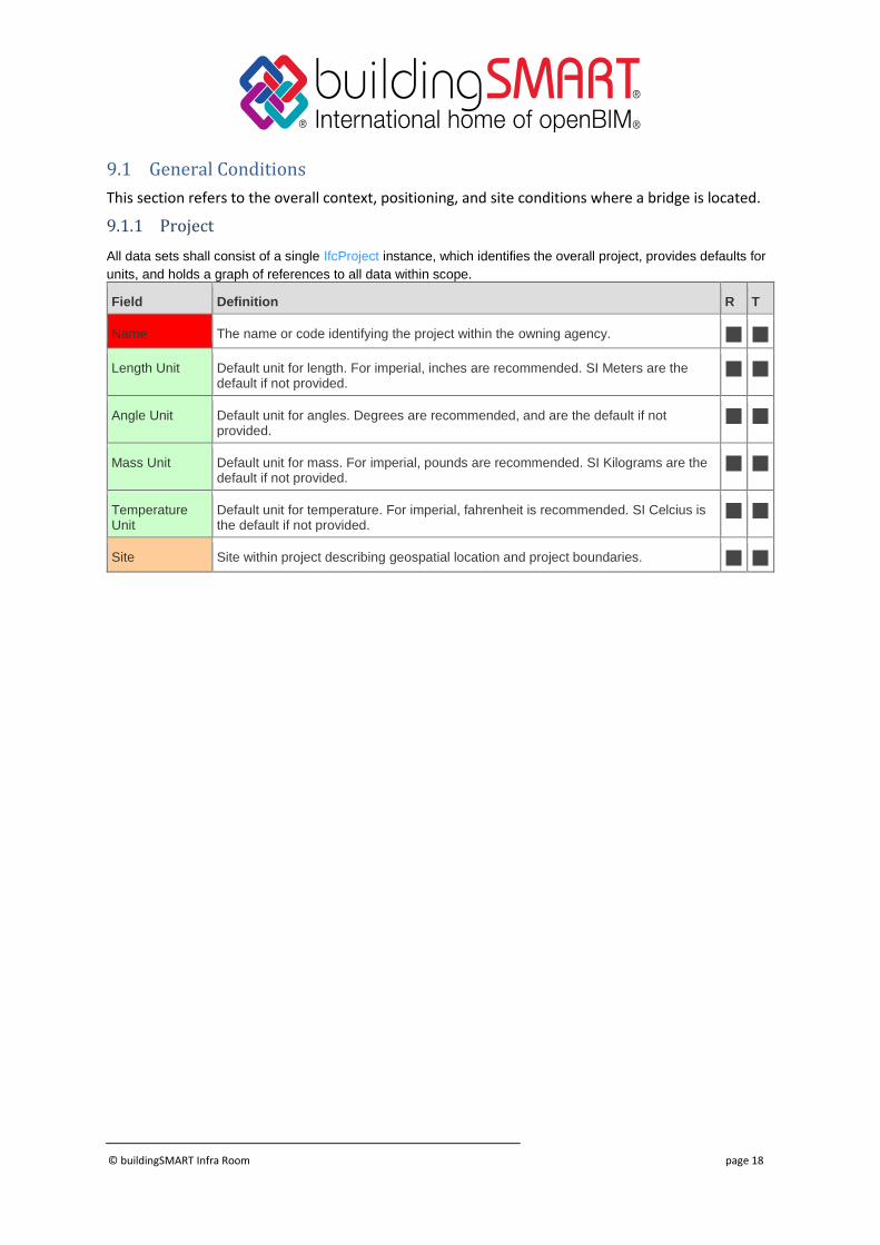
9.1.1 Project
All data sets shall consist of a single IfcProject instance, which identifies the overall project, provides defaults for
units, and holds a graph of references to all data within scope.
Field Definition R T
Name The name or code identifying the project within the owning agency.
Length Unit Default unit for length. For imperial, inches are recommended. SI Meters are the default if not provided.
Angle Unit Default unit for angles. Degrees are recommended, and are the default if not provided.
Mass Unit Default unit for mass. For imperial, pounds are recommended. SI Kilograms are the default if not provided.
Temperature Unit
Default unit for temperature. For imperial, fahrenheit is recommended. SI Celcius is the default if not provided.
Site Site within project describing geospatial location and project boundaries.
© buildingSMART Infra Room page 19
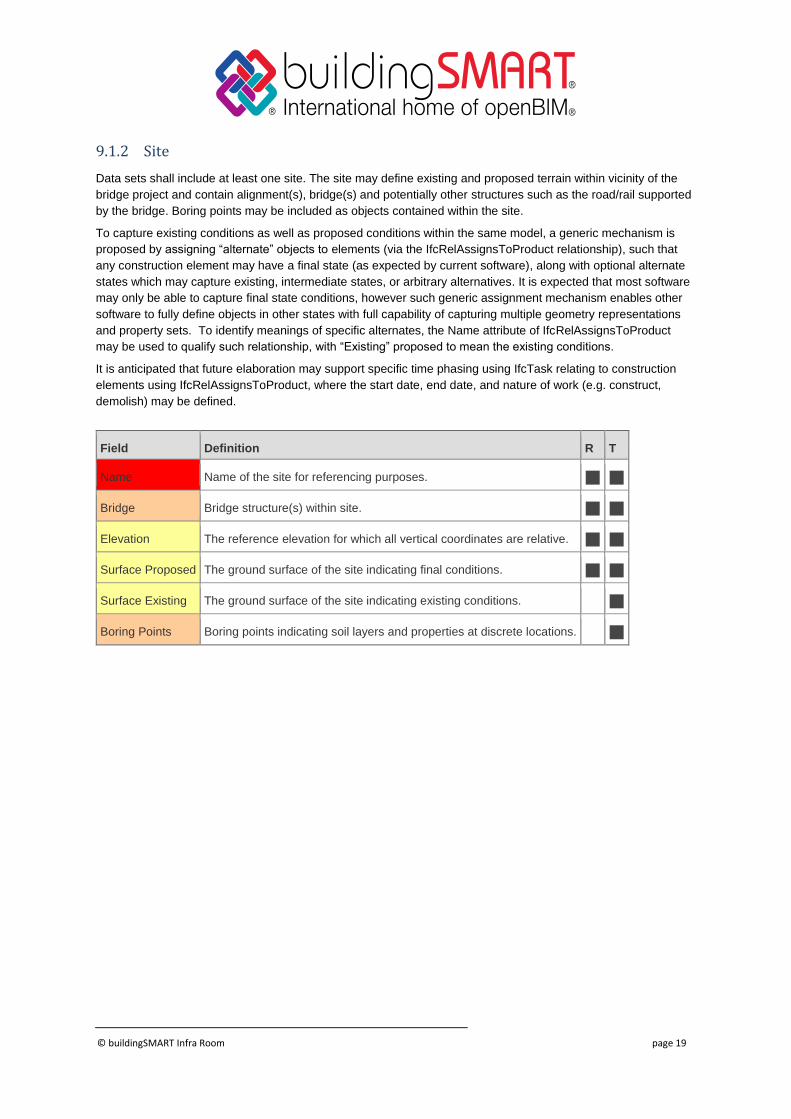
9.1.2 Site
Data sets shall include at least one site. The site may define existing and proposed terrain within vicinity of the
bridge project and contain alignment(s), bridge(s) and potentially other structures such as the road/rail supported
by the bridge. Boring points may be included as objects contained within the site.
To capture existing conditions as well as proposed conditions within the same model, a generic mechanism is
proposed by assigning “alternate” objects to elements (via the IfcRelAssignsToProduct relationship), such that
any construction element may have a final state (as expected by current software), along with optional alternate
states which may capture existing, intermediate states, or arbitrary alternatives. It is expected that most software
may only be able to capture final state conditions, however such generic assignment mechanism enables other
software to fully define objects in other states with full capability of capturing multiple geometry representations
and property sets. To identify meanings of specific alternates, the Name attribute of IfcRelAssignsToProduct
may be used to qualify such relationship, with “Existing” proposed to mean the existing conditions.
It is anticipated that future elaboration may support specific time phasing using IfcTask relating to construction
elements using IfcRelAssignsToProduct, where the start date, end date, and nature of work (e.g. construct,
demolish) may be defined.
Field Definition R T
Name Name of the site for referencing purposes.
Bridge Bridge structure(s) within site.
Elevation The reference elevation for which all vertical coordinates are relative.
Surface Proposed The ground surface of the site indicating final conditions.
Surface Existing The ground surface of the site indicating existing conditions.
Boring Points Boring points indicating soil layers and properties at discrete locations.
© buildingSMART Infra Room page 20
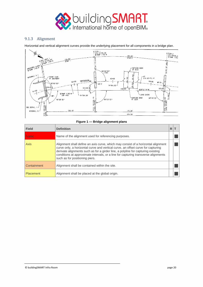
9.1.3 Alignment
Horizontal and vertical alignment curves provide the underlying placement for all components in a bridge plan.
Figure 1 — Bridge alignment plans
Field Definition R T
Name Name of the alignment used for referencing purposes.
Axis Alignment shall define an axis curve, which may consist of a horizontal alignment curve only, a horizontal curve and vertical curve, an offset curve for capturing derivate alignments such as for a girder line, a polyline for capturing existing conditions at approximate intervals, or a line for capturing transverse alignments such as for positioning piers.
Containment Alignment shall be contained within the site.
Placement Alignment shall be placed at the global origin.
© buildingSMART Infra Room page 21
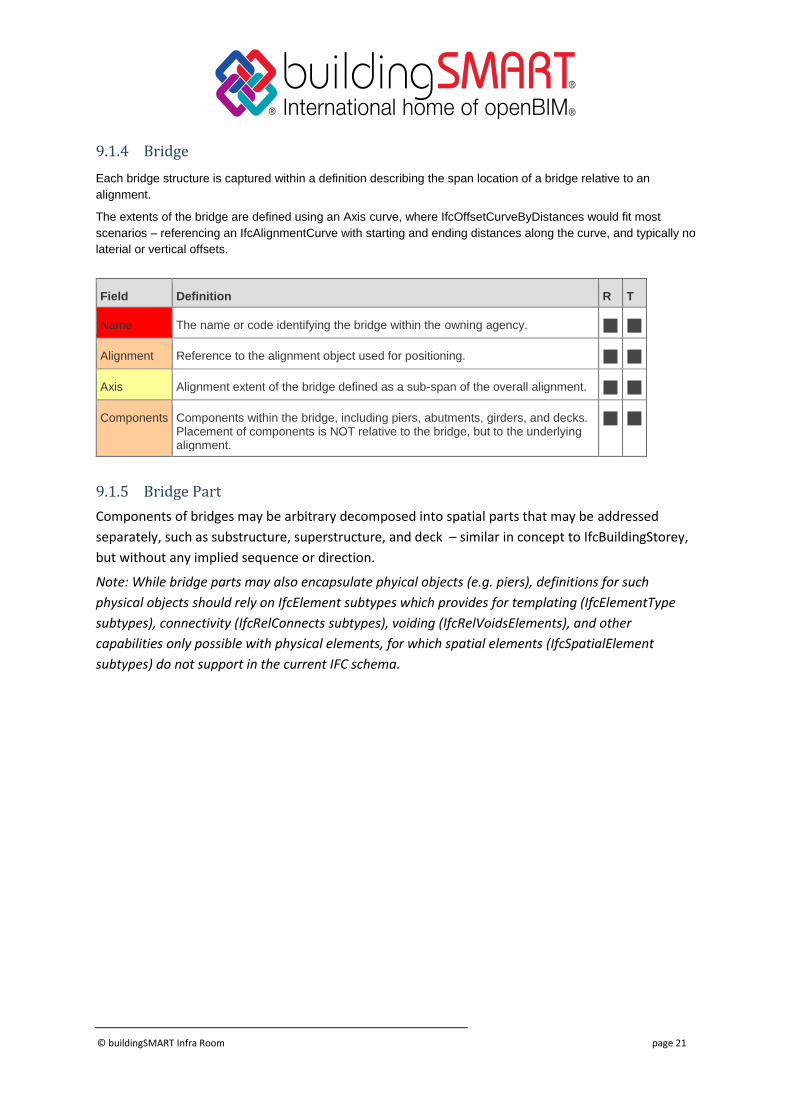
9.1.4 Bridge
Each bridge structure is captured within a definition describing the span location of a bridge relative to an
alignment.
The extents of the bridge are defined using an Axis curve, where IfcOffsetCurveByDistances would fit most
scenarios – referencing an IfcAlignmentCurve with starting and ending distances along the curve, and typically no
laterial or vertical offsets.
Field Definition R T
Name The name or code identifying the bridge within the owning agency.
Alignment Reference to the alignment object used for positioning.
Axis Alignment extent of the bridge defined as a sub-span of the overall alignment.
Components Components within the bridge, including piers, abutments, girders, and decks. Placement of components is NOT relative to the bridge, but to the underlying alignment.
9.1.5 Bridge Part
Components of bridges may be arbitrary decomposed into spatial parts that may be addressed
separately, such as substructure, superstructure, and deck – similar in concept to IfcBuildingStorey,
but without any implied sequence or direction.
Note: While bridge parts may also encapsulate phyical objects (e.g. piers), definitions for such
physical objects should rely on IfcElement subtypes which provides for templating (IfcElementType
subtypes), connectivity (IfcRelConnects subtypes), voiding (IfcRelVoidsElements), and other
capabilities only possible with physical elements, for which spatial elements (IfcSpatialElement
subtypes) do not support in the current IFC schema.
© buildingSMART Infra Room page 22
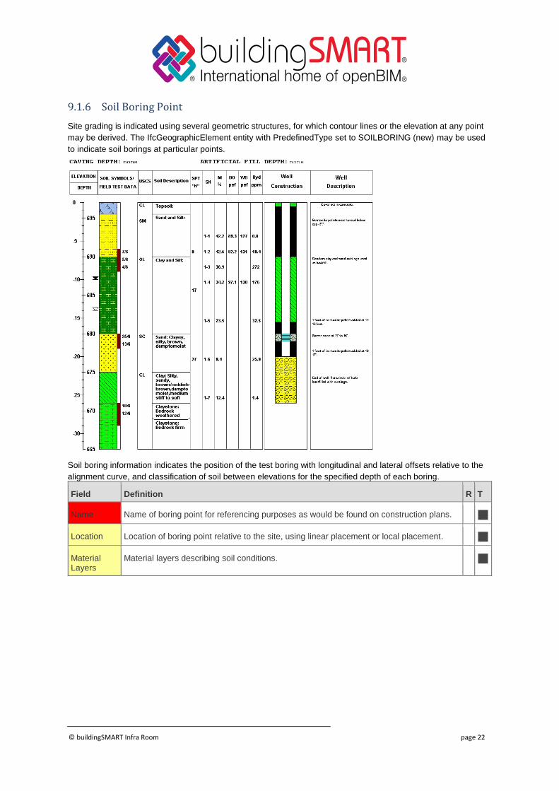
9.1.6 Soil Boring Point
Site grading is indicated using several geometric structures, for which contour lines or the elevation at any point
may be derived. The IfcGeographicElement entity with PredefinedType set to SOILBORING (new) may be used
to indicate soil borings at particular points.
Soil boring information indicates the position of the test boring with longitudinal and lateral offsets relative to the
alignment curve, and classification of soil between elevations for the specified depth of each boring.
Field Definition R T
Name Name of boring point for referencing purposes as would be found on construction plans.
Location Location of boring point relative to the site, using linear placement or local placement.
Material Layers
Material layers describing soil conditions.
© buildingSMART Infra Room page 23
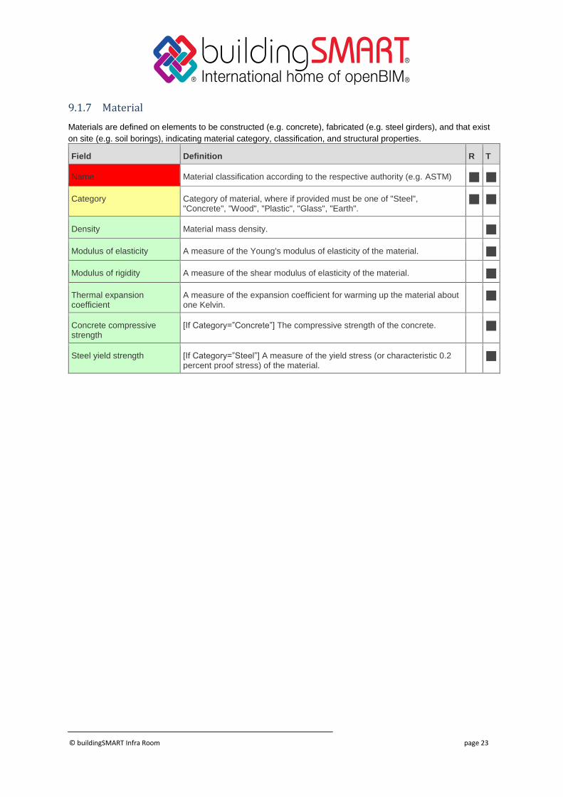
9.1.7 Material
Materials are defined on elements to be constructed (e.g. concrete), fabricated (e.g. steel girders), and that exist
on site (e.g. soil borings), indicating material category, classification, and structural properties.
Field Definition R T
Name Material classification according to the respective authority (e.g. ASTM)
Category Category of material, where if provided must be one of "Steel", "Concrete", "Wood", "Plastic", "Glass", "Earth".
Density Material mass density.
Modulus of elasticity A measure of the Young's modulus of elasticity of the material.
Modulus of rigidity A measure of the shear modulus of elasticity of the material.
Thermal expansion coefficient
A measure of the expansion coefficient for warming up the material about one Kelvin.
Concrete compressive strength
[If Category=”Concrete”] The compressive strength of the concrete.
Steel yield strength [If Category=”Steel”] A measure of the yield stress (or characteristic 0.2 percent proof stress) of the material.
© buildingSMART Infra Room page 24
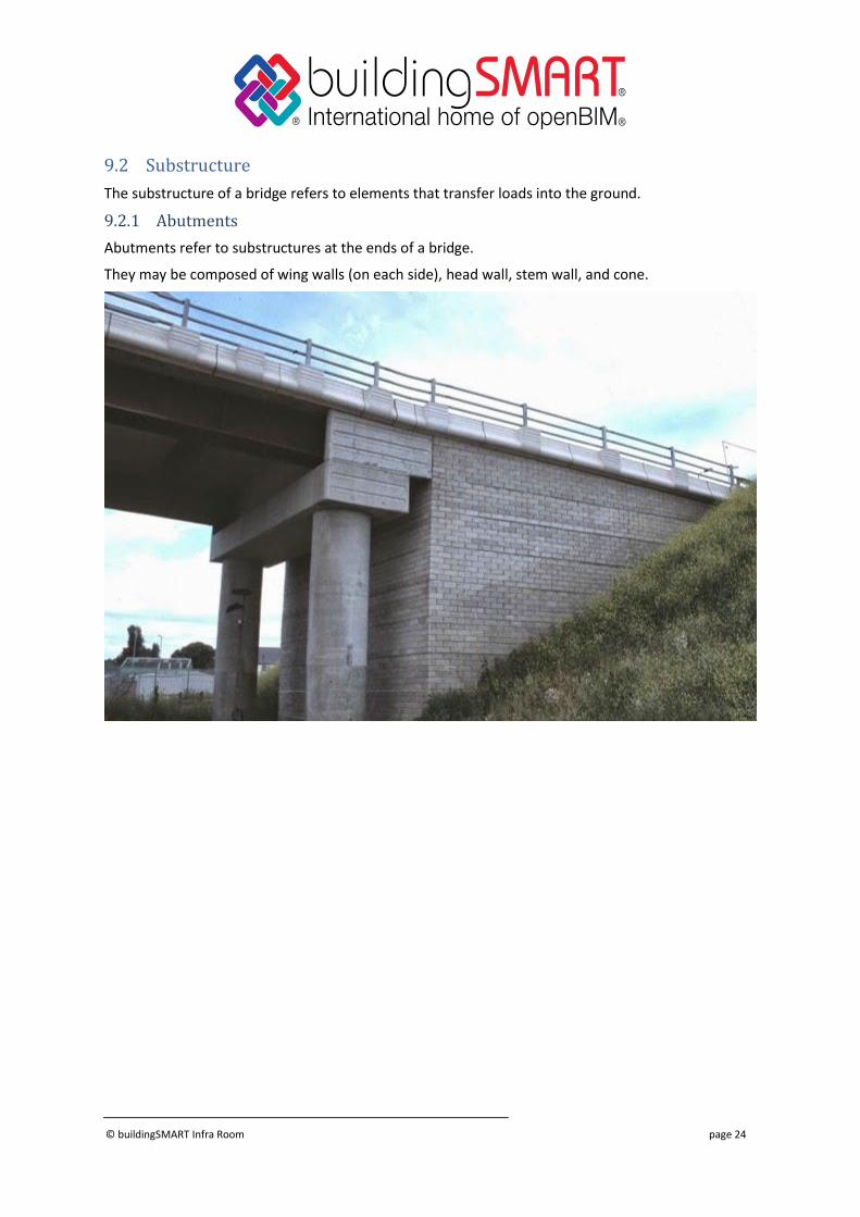
9.2 Substructure
The substructure of a bridge refers to elements that transfer loads into the ground.
9.2.1 Abutments
Abutments refer to substructures at the ends of a bridge.
They may be composed of wing walls (on each side), head wall, stem wall, and cone.
© buildingSMART Infra Room page 25
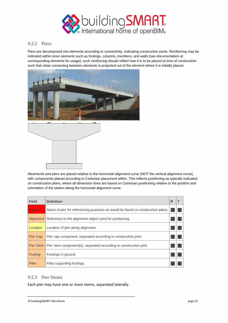
9.2.2 Piers
Piers are decomposed into elements according to connectivity, indicating construction joints. Reinforcing may be
indicated within inner elements such as footings, columns, members, and walls (see documentation at
corresponding elements for usage); such reinforcing should reflect how it is to be placed at time of construction
such that rebar connecting between elements is projected out of the element where it is initially placed.
Abutments and piers are placed relative to the horizontal alignment curve (NOT the vertical alignment curve),
with components placed according to Cartesian placement within. This reflects positioning as typically indicated
on construction plans, where all dimension lines are based on Cartesian positioning relative to the position and
orientation of the station along the horizontal alignment curve.
Field Definition R T
Name Name of pier for referencing purposes as would be found on construction plans.
Alignment Reference to the alignment object used for positioning.
Location Location of pier along alignment.
Pier Cap Pier cap component, separated according to construction joint.
Pier Stem Pier stem component(s), separated according to construction joint.
Footing Footings in ground.
Piles Piles supporting footings.
9.2.3 Pier Stems
Each pier may have one or more stems, separated laterally.

© buildingSMART Infra Room page 26
9.2.4 Pier Segments
Each pier stem may have one or more segments, separated by construction joint.
9.2.5 Pier Caps
Each pier may have a top that spans stem(s). If such cap is above a bearing, then it is modelled as
part of the superstructure.
© buildingSMART Infra Room page 27
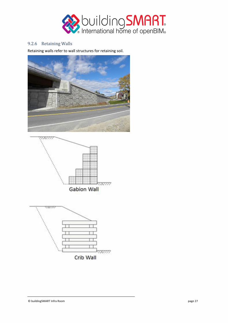
9.2.6 Retaining Walls
Retaining walls refer to wall structures for retaining soil.
© buildingSMART Infra Room page 28
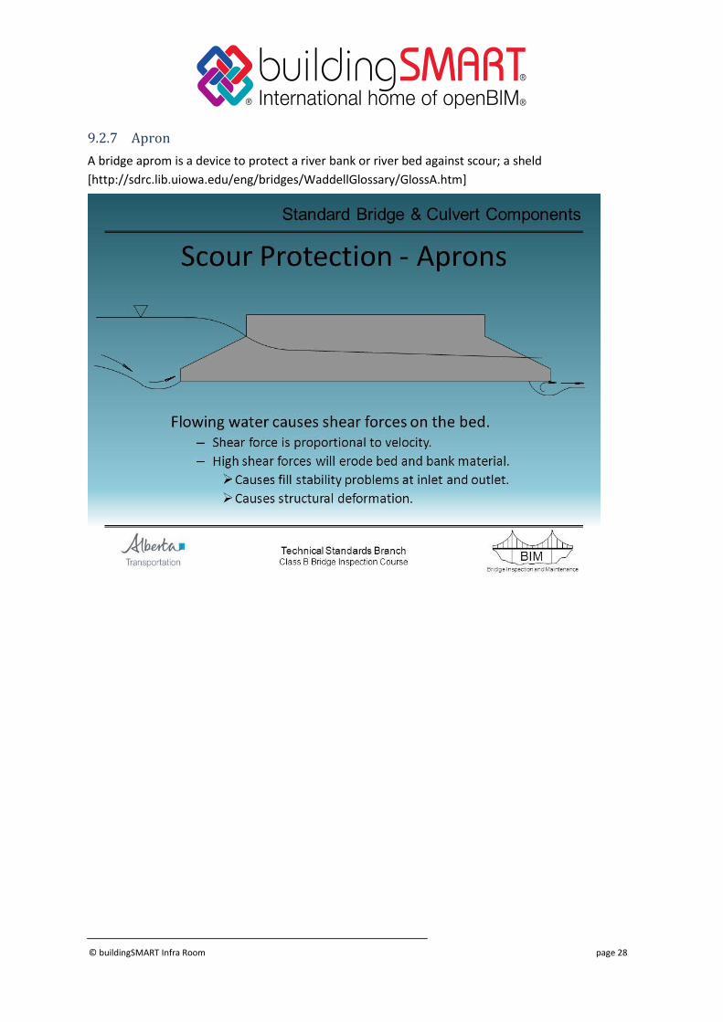
9.2.7 Apron
A bridge aprom is a device to protect a river bank or river bed against scour; a sheld
[http://sdrc.lib.uiowa.edu/eng/bridges/WaddellGlossary/GlossA.htm]
© buildingSMART Infra Room page 29
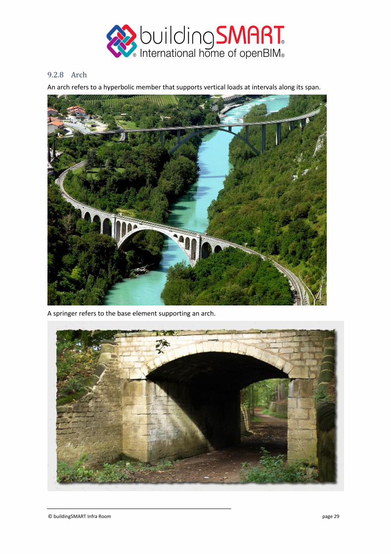
9.2.8 Arch
An arch refers to a hyperbolic member that supports vertical loads at intervals along its span.
A springer refers to the base element supporting an arch.
© buildingSMART Infra Room page 30
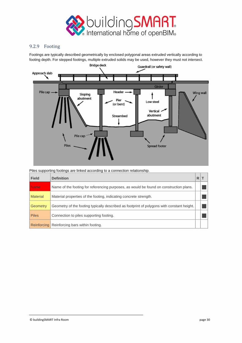
9.2.9 Footing
Footings are typically described geometrically by enclosed polygonal areas extruded vertically according to
footing depth. For stepped footings, multiple extruded solids may be used, however they must not intersect.
Piles supporting footings are linked according to a connection relationship.
Field Definition R T
Name Name of the footing for referencing purposes, as would be found on construction plans.
Material Material properties of the footing, indicating concrete strength.
Geometry Geometry of the footing typically described as footprint of polygons with constant height.
Piles Connection to piles supporting footing.
Reinforcing Reinforcing bars within footing.
© buildingSMART Infra Room page 31
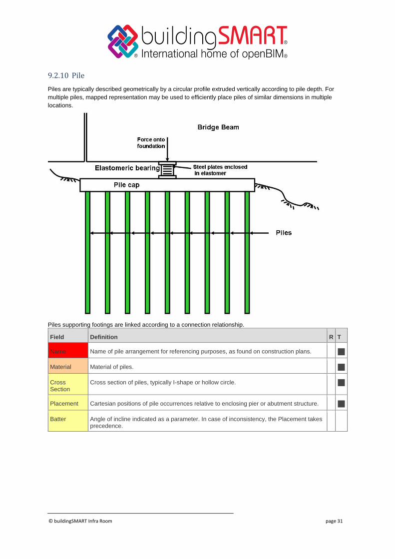
9.2.10 Pile
Piles are typically described geometrically by a circular profile extruded vertically according to pile depth. For
multiple piles, mapped representation may be used to efficiently place piles of similar dimensions in multiple
locations.
Piles supporting footings are linked according to a connection relationship.
Field Definition R T
Name Name of pile arrangement for referencing purposes, as found on construction plans.
Material Material of piles.
Cross Section
Cross section of piles, typically I-shape or hollow circle.
Placement Cartesian positions of pile occurrences relative to enclosing pier or abutment structure.
Batter Angle of incline indicated as a parameter. In case of inconsistency, the Placement takes precedence.
© buildingSMART Infra Room page 32
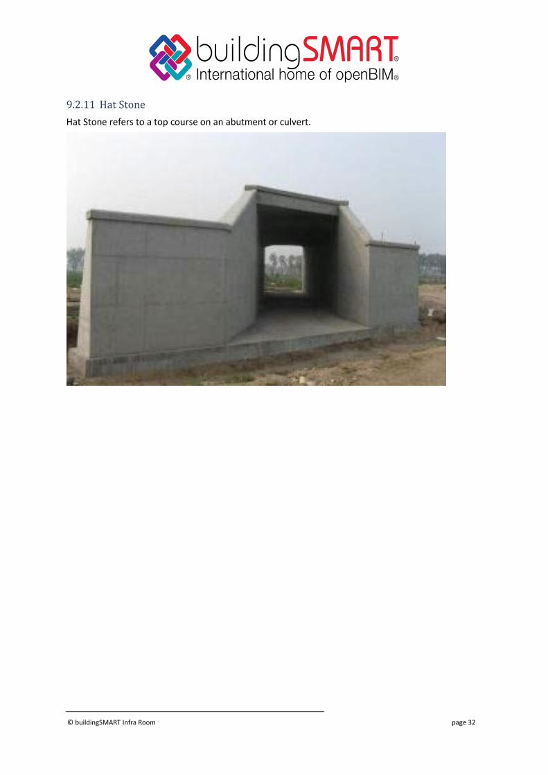
9.2.11 Hat Stone
Hat Stone refers to a top course on an abutment or culvert.
© buildingSMART Infra Room page 33
9.3 Superstructure
The superstructure of a bridge refers to those elements than span horizontally to carry loads onto
substructures.
Field Definition R T
Name Name of the superstructure for organizational purposes.
Alignments Alignment objects used longitudinally (e.g. for girders) or laterally (e.g. for floor beams).
Trusses Truss lines.
Girders Girder lines.
Cross Frames
Cross frames between girder lines.
Floor Beams Floor beams between girder lines.
Stringers Stringers between floor beams.
9.3.1 Girder
Bridge girders refer to horizontal support beams that span along the alignment of a bridge.
For steel girders, this refers to each girder line, decomposed into beam segments.
For concrete box girders, this refers to the overall box girder, typically connected to the bridge deck via a keyed
construction joint with adjoining reinforcing.
Field Definition R T
Name Name of the girder line for referencing purposes as would be found on construction plans.
Alignment Reference to the alignment object used to position the girder line.
Axis Axis curve defined as a sub-span with offsets relative to the alignment curve.

© buildingSMART Infra Room page 34
Type Template defining general construction that may be used across projects.
Material Common material that applies to all segments of the girder.
Segments Segmented girders may be decomposed into segments for each continuous section.
Components Built-up girders may be decomposed into plates (or members) for web, flanges, cover plates, longitudinal stiffeners, and vertical stiffeners.
© buildingSMART Infra Room page 35
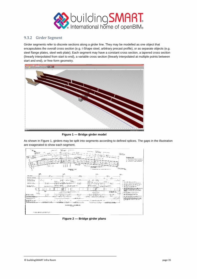
9.3.2 Girder Segment
Girder segments refer to discrete sections along a girder line. They may be modelled as one object that
encapsulates the overall cross section (e.g. I-Shape steel, arbitrary precast profile), or as separate objects (e.g.
steel flange plates, steel web plate). Each segment may have a constant cross section, a tapered cross section
(linearly interpolated from start to end), a variable cross section (linearly interpolated at multiple points between
start and end), or free-form geometry.
Figure 1 — Bridge girder model
As shown in Figure 1, girders may be split into segments according to defined splices. The gaps in the illustration
are exagerated to show each segment.
Figure 2 — Bridge girder plans
© buildingSMART Infra Room page 36
The connection between beams is represented using IfcRelConnectsWithRealizingElements, where
the RealizingElements refers to IfcPlate elements for fastening plates on each side, IfcFastener for bolts,
and IfcPlate for any flange transition plates. The reason for using this connection relationship specifically (as
opposed to just placing the elements) is to be able to derive an IfcStructuralAnalysisModel that captures the
beam connectivity.
Field Definition R T
Name Name of the girder segment for referencing purposes as would be found on construction plans.
Material Material of the girder segment.
Solid Geometry
Geometry of the girder segment defined as a cross section that may be constant or variable (linearly or parabolic), swept along the alignment at starting and ending positions.
Connection Head
Relationship connecting head of girder segment with abutment or another girder segment, where realizing element refers to splice plates.
Connection Tail
Relationship connecting tail of girder segment with another girder segment or abutment, where realizing element refers to splice plates.
Connection Support
Relationship connecting girder segment to substructure, where realizing element refers to bearing if present.
Reinforcing For concrete girders, reinforcing embedded.
Tendons For concrete girders, tendons embedded.
Stiffeners For steel girders, web stiffeners placed at intervals along inside face(s) of web.
Shear Studs For steel girders, shear studs placed at intervals along top flange.
Camber For steel girders, camber ordinates for fabrication.
© buildingSMART Infra Room page 37
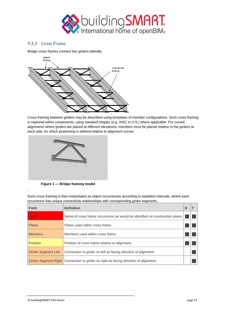
9.3.3 Cross Frame
Bridge cross frames connect two girders laterally.
Cross-framing between girders may be described using templates of member configurations. Such cross framing
is captured within components, using standard shapes (e.g. AISC in U.S.) where applicable. For curved
alignments where girders are placed at different elevations, members must be placed relative to the girders at
each side, for which positioning is defined relative to alignment curves.
Figure 1 — Bridge framing model
.
Such cross-framing is then instantiated as object occurrences according to repetition intervals, where each
occurrence has unique connectivity relationships with corresponding girder segments.
Field Definition R T
Name Name of cross frame occurrence as would be identified on construction plans.
Plates Plates used within cross frame.
Members Members used within cross frame.
Position Position of cross frame relative to alignment.
Girder Segment Left Connection to girder on left as facing direction of alignment.
Girder Segment Right Connection to girder on right as facing direction of alignment.
© buildingSMART Infra Room page 38
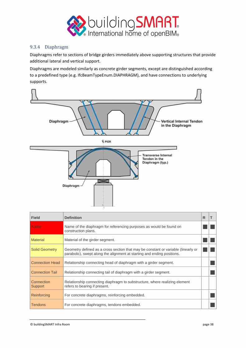
9.3.4 Diaphragm
Diaphragms refer to sections of bridge girders immediately above supporting structures that provide
additional lateral and vertical support.
Diaphragms are modeled similarly as concrete girder segments, except are distinguished according
to a predefined type (e.g. IfcBeamTypeEnum.DIAPHRAGM), and have connections to underlying
supports.
Field Definition R T
Name Name of the diaphragm for referencing purposes as would be found on construction plans.
Material Material of the girder segment.
Solid Geometry Geometry defined as a cross section that may be constant or variable (linearly or parabolic), swept along the alignment at starting and ending positions.
Connection Head Relationship connecting head of diaphragm with a girder segment.
Connection Tail Relationship connecting tail of diaphragm with a girder segment.
Connection Support
Relationship connecting diaphragm to substructure, where realizing element refers to bearing if present.
Reinforcing For concrete diaphragms, reinforcing embedded.
Tendons For concrete diaphragms, tendons embedded.

© buildingSMART Infra Room page 39
© buildingSMART Infra Room page 40
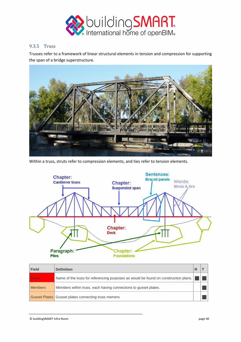
9.3.5 Truss
Trusses refer to a framework of linear structural elements in tension and compression for supporting
the span of a bridge superstructure.
Within a truss, struts refer to compression elements, and ties refer to tension elements.
Field Definition R T
Name Name of the truss for referencing purposes as would be found on construction plans.
Members Members within truss, each having connections to gusset plates.
Gusset Plates Gusset plates connecting truss memers

© buildingSMART Infra Room page 41
Connections Relationships connecting truss to other superstructure elements
© buildingSMART Infra Room page 42
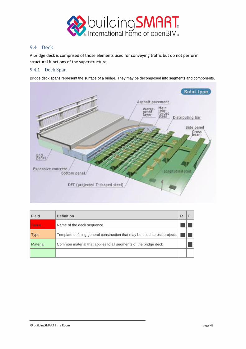
9.4 Deck
A bridge deck is comprised of those elements used for conveying traffic but do not perform
structural functions of the superstructure.
9.4.1 Deck Span
Bridge deck spans represent the surface of a bridge. They may be decomposed into segments and components.
Field Definition R T
Name Name of the deck sequence.
Type Template defining general construction that may be used across projects.
Material Common material that applies to all segments of the bridge deck
© buildingSMART Infra Room page 43
9.4.2 Deck Segment
This entity may be used to model segments of a bridge deck, separated by construction or expansion joint.
Geometry for bridge decks is typically represented using IfcSectionedSolidHorizontal for defining a cross section
that may potentially vary along an alignment.
Field Definition R T
Name Name of the deck segment for referencing purposes as would be found on construction plans.
Surface For reference, surface geometry is only needed for visualization purposes.
Material Material of the deck segment.
Solid Geometry
Geometry of the deck segment, including any haunches, defined as a cross section that may be constant or variable (linearly or parabolic), swept along the alignment at starting and ending positions.
Connection Head
Relationship connecting head of deck segment with abutment or another deck segment.
Connection Tail
Relationship connecting tail of deck segment with another deck segment or abutment.
Connection Girders
Relationship connecting deck segment to supporting girder(s).
Reinforcing Reinforcing embedded within deck.
Drainage Waste terminals embedded within deck.
© buildingSMART Infra Room page 44
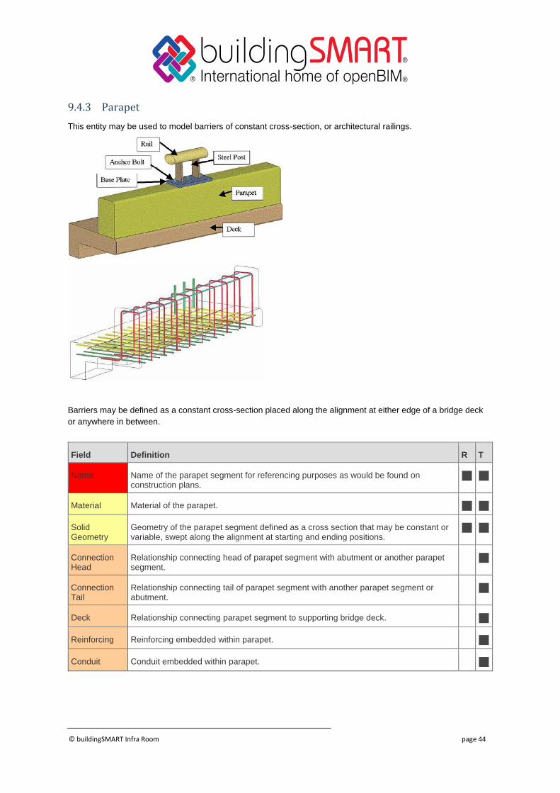
9.4.3 Parapet
This entity may be used to model barriers of constant cross-section, or architectural railings.
Barriers may be defined as a constant cross-section placed along the alignment at either edge of a bridge deck
or anywhere in between.
Field Definition R T
Name Name of the parapet segment for referencing purposes as would be found on construction plans.
Material Material of the parapet.
Solid Geometry
Geometry of the parapet segment defined as a cross section that may be constant or variable, swept along the alignment at starting and ending positions.
Connection Head
Relationship connecting head of parapet segment with abutment or another parapet segment.
Connection Tail
Relationship connecting tail of parapet segment with another parapet segment or abutment.
Deck Relationship connecting parapet segment to supporting bridge deck.
Reinforcing Reinforcing embedded within parapet.
Conduit Conduit embedded within parapet.
© buildingSMART Infra Room page 45
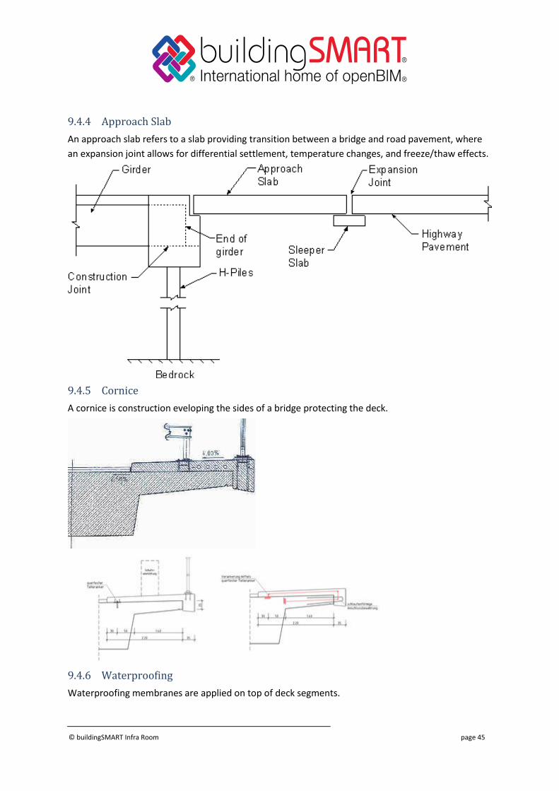
9.4.4 Approach Slab
An approach slab refers to a slab providing transition between a bridge and road pavement, where
an expansion joint allows for differential settlement, temperature changes, and freeze/thaw effects.
9.4.5 Cornice
A cornice is construction eveloping the sides of a bridge protecting the deck.
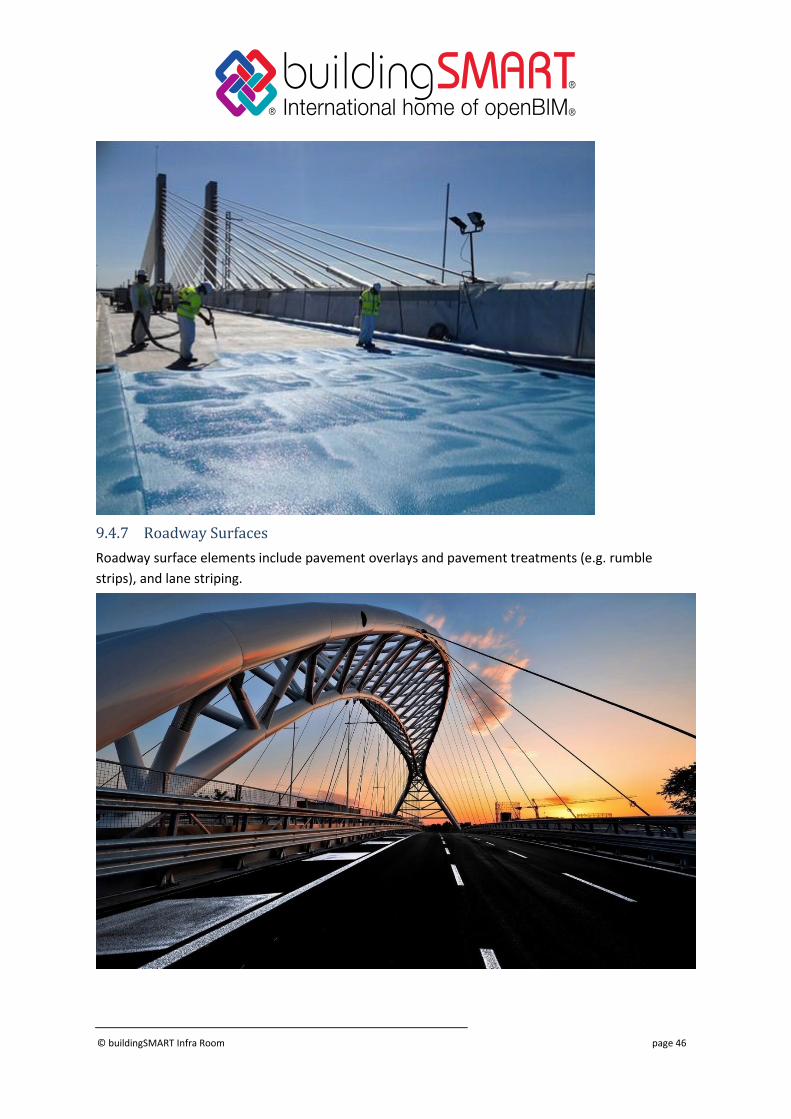
9.4.6 Waterproofing
Waterproofing membranes are applied on top of deck segments.
© buildingSMART Infra Room page 46
9.4.7 Roadway Surfaces
Roadway surface elements include pavement overlays and pavement treatments (e.g. rumble
strips), and lane striping.
© buildingSMART Infra Room page 47
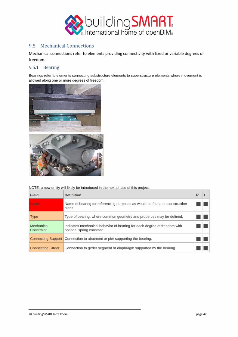
9.5 Mechanical Connections
Mechanical connections refer to elements providing connectivity with fixed or variable degrees of
freedom.
9.5.1 Bearing
Bearings refer to elements connecting substructure elements to superstructure elements where movement is
allowed along one or more degrees of freedom.
NOTE: a new entity will likely be introduced in the next phase of this project.
Field Definition R T
Name Name of bearing for referencing purposes as would be found on construction plans.
Type Type of bearing, where common geometry and properties may be defined.
Mechanical Constraint
Indicates mechanical behavior of bearing for each degree of freedom with optional spring constant.
Connecting Support Connection to abutment or pier supporting the bearing.
Connecting Girder Connection to girder segment or diaphragm supported by the bearing.
© buildingSMART Infra Room page 48
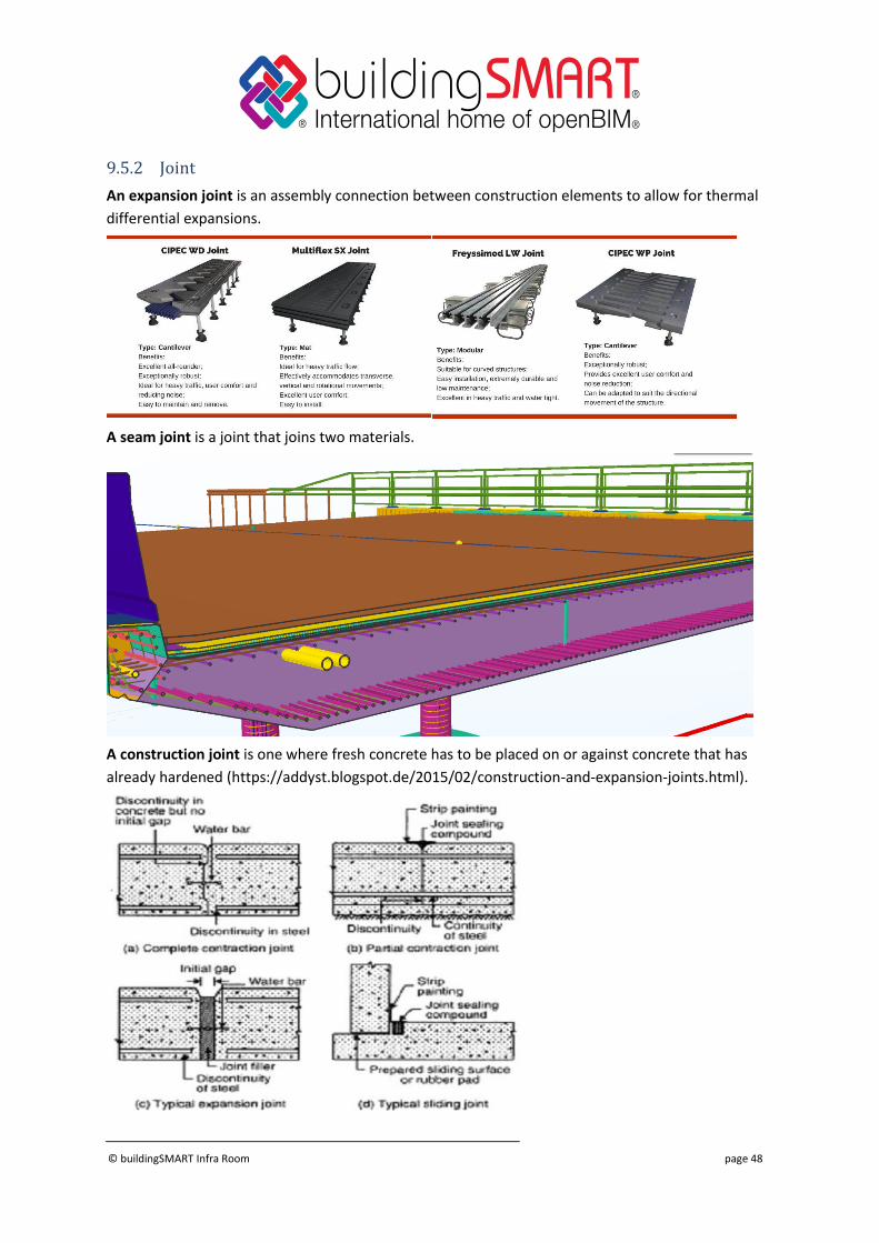
9.5.2 Joint
An expansion joint is an assembly connection between construction elements to allow for thermal
differential expansions.
A seam joint is a joint that joins two materials.
A construction joint is one where fresh concrete has to be placed on or against concrete that has
already hardened (https://addyst.blogspot.de/2015/02/construction-and-expansion-joints.html).

© buildingSMART Infra Room page 49
Field Definition R T
Name Name of joint for referencing purposes as would be found on construction plans.
Type Type of joint, where common geometry and properties may be defined.
Expansion Extent Indicates the length available for expansion.
Connection Head Reference to deck segment or pavement at head
Connection Tail Reference to deck segment or pavement at tail
© buildingSMART Infra Room page 50
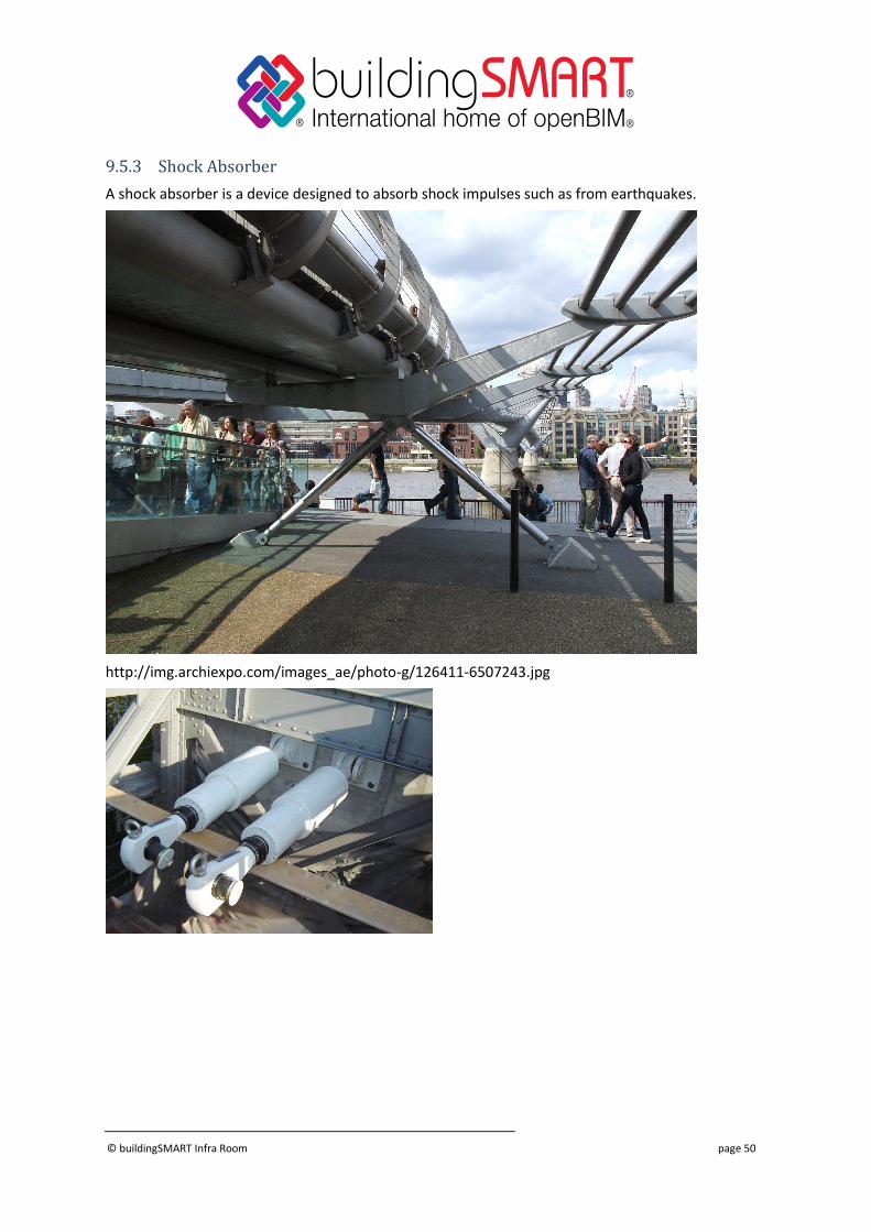
9.5.3 Shock Absorber
A shock absorber is a device designed to absorb shock impulses such as from earthquakes.
http://img.archiexpo.com/images_ae/photo-g/126411-6507243.jpg
© buildingSMART Infra Room page 51
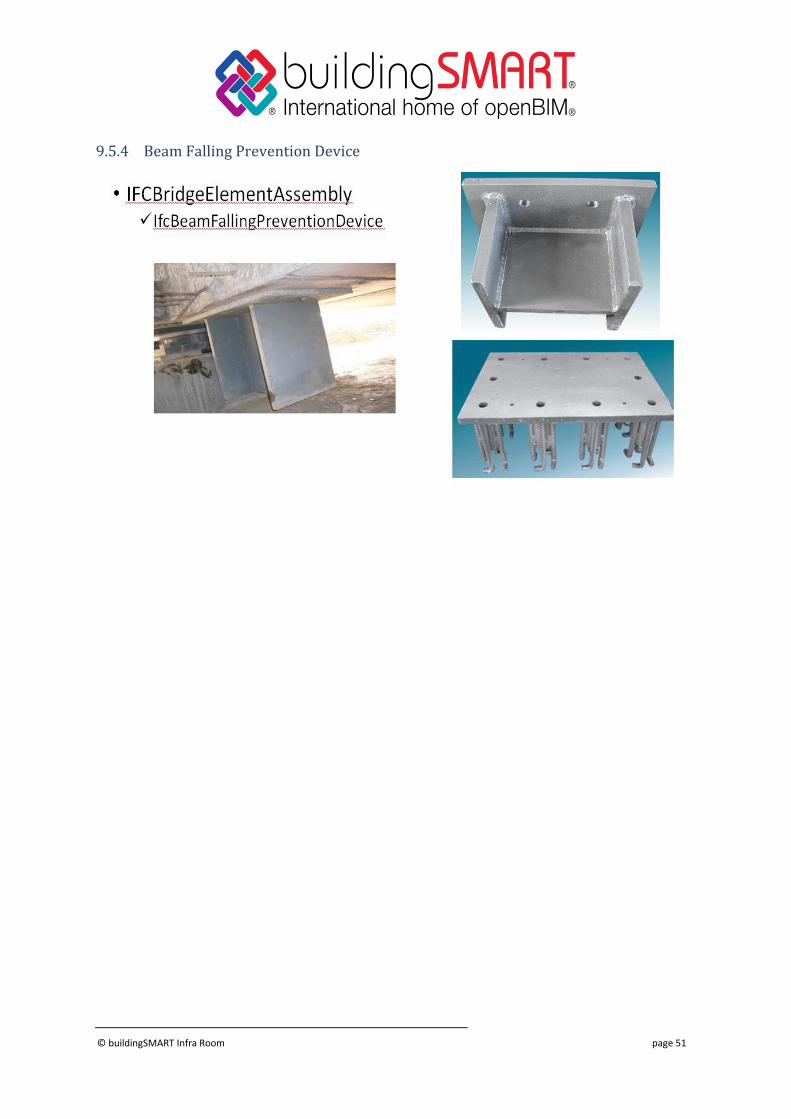
9.5.4 Beam Falling Prevention Device
© buildingSMART Infra Room page 52
9.6 Reinforcement and Prestressing
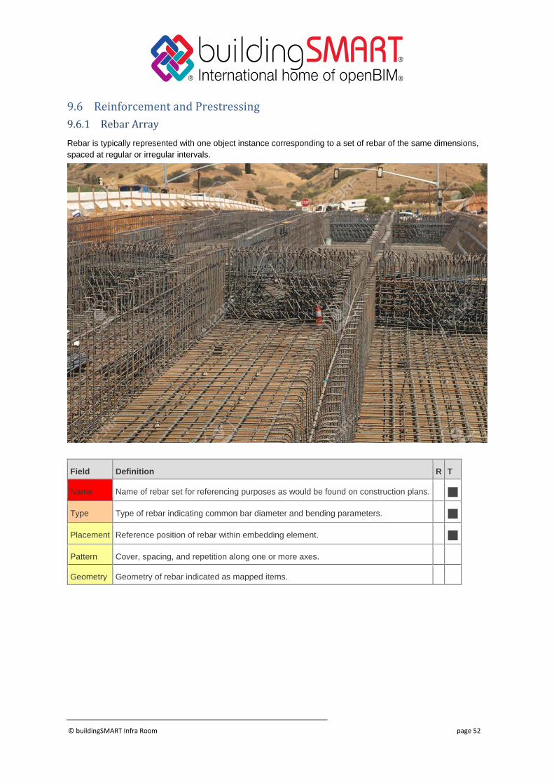
9.6.1 Rebar Array
Rebar is typically represented with one object instance corresponding to a set of rebar of the same dimensions,
spaced at regular or irregular intervals.
Field Definition R T
Name Name of rebar set for referencing purposes as would be found on construction plans.
Type Type of rebar indicating common bar diameter and bending parameters.
Placement Reference position of rebar within embedding element.
Pattern Cover, spacing, and repetition along one or more axes.
Geometry Geometry of rebar indicated as mapped items.
© buildingSMART Infra Room page 53
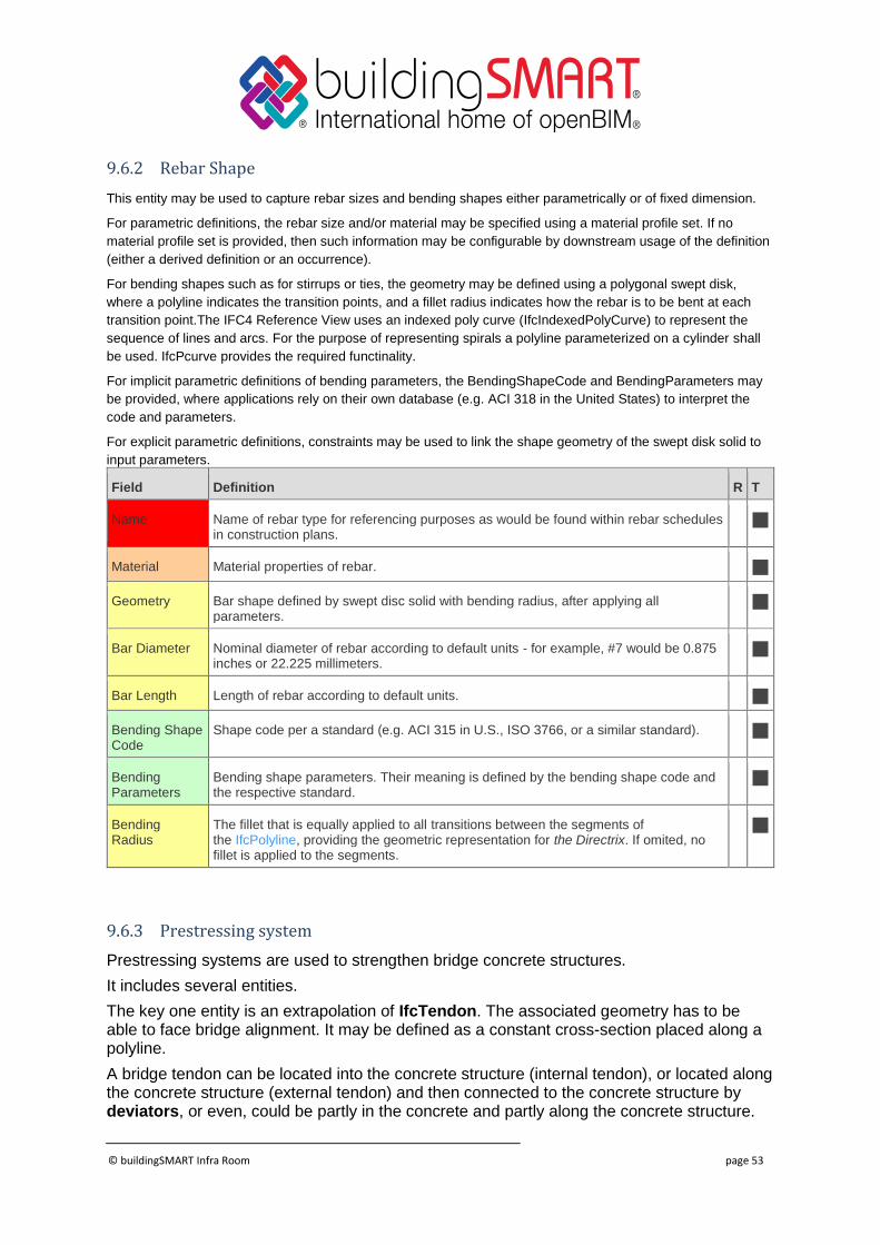
9.6.2 Rebar Shape
This entity may be used to capture rebar sizes and bending shapes either parametrically or of fixed dimension.
For parametric definitions, the rebar size and/or material may be specified using a material profile set. If no
material profile set is provided, then such information may be configurable by downstream usage of the definition
(either a derived definition or an occurrence).
For bending shapes such as for stirrups or ties, the geometry may be defined using a polygonal swept disk,
where a polyline indicates the transition points, and a fillet radius indicates how the rebar is to be bent at each
transition point.The IFC4 Reference View uses an indexed poly curve (IfcIndexedPolyCurve) to represent the
sequence of lines and arcs. For the purpose of representing spirals a polyline parameterized on a cylinder shall
be used. IfcPcurve provides the required functinality.
For implicit parametric definitions of bending parameters, the BendingShapeCode and BendingParameters may
be provided, where applications rely on their own database (e.g. ACI 318 in the United States) to interpret the
code and parameters.
For explicit parametric definitions, constraints may be used to link the shape geometry of the swept disk solid to
input parameters.
Field Definition R T
Name Name of rebar type for referencing purposes as would be found within rebar schedules in construction plans.
Material Material properties of rebar.
Geometry Bar shape defined by swept disc solid with bending radius, after applying all parameters.
Bar Diameter Nominal diameter of rebar according to default units - for example, #7 would be 0.875 inches or 22.225 millimeters.
Bar Length Length of rebar according to default units.
Bending Shape Code
Shape code per a standard (e.g. ACI 315 in U.S., ISO 3766, or a similar standard).
Bending Parameters
Bending shape parameters. Their meaning is defined by the bending shape code and the respective standard.
Bending Radius
The fillet that is equally applied to all transitions between the segments of the IfcPolyline, providing the geometric representation for the Directrix. If omited, no fillet is applied to the segments.
9.6.3 Prestressing system
Prestressing systems are used to strengthen bridge concrete structures.
It includes several entities.
The key one entity is an extrapolation of IfcTendon. The associated geometry has to be able to face bridge alignment. It may be defined as a constant cross-section placed along a polyline.
A bridge tendon can be located into the concrete structure (internal tendon), or located along the concrete structure (external tendon) and then connected to the concrete structure by deviators, or even, could be partly in the concrete and partly along the concrete structure.
© buildingSMART Infra Room page 54
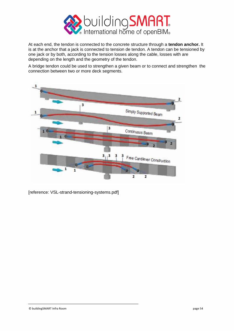
At each end, the tendon is connected to the concrete structure through a tendon anchor. It is at the anchor that a jack is connected to tension de tendon. A tendon can be tensioned by one jack or by both, according to the tension losses along the cable, losses with are depending on the length and the geometry of the tendon.
A bridge tendon could be used to strengthen a given beam or to connect and strengthen the connection between two or more deck segments.
[reference: VSL-strand-tensioning-systems.pdf]
© buildingSMART Infra Room page 55
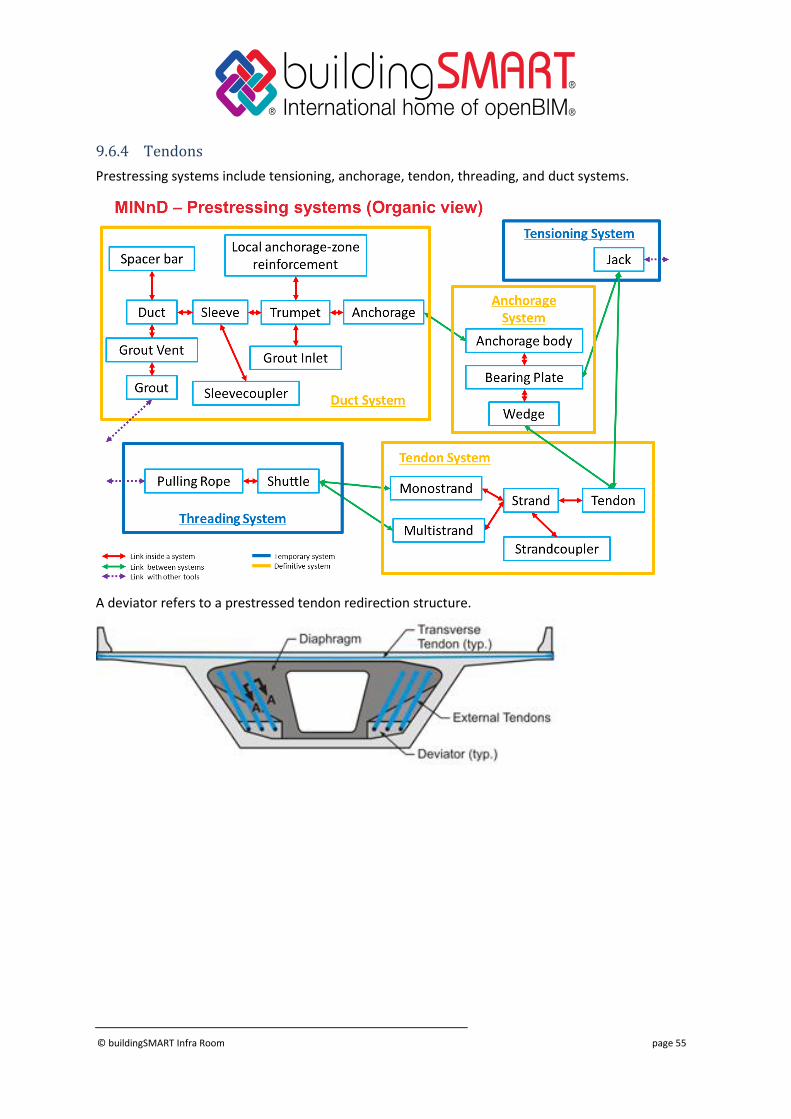
9.6.4 Tendons
Prestressing systems include tensioning, anchorage, tendon, threading, and duct systems.
A deviator refers to a prestressed tendon redirection structure.
© buildingSMART Infra Room page 56
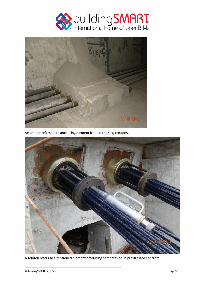
An anchor refers to an anchoring element for prestressing tendons.
A tendon refers to a tensioned element producing compression in prestressed concrete.
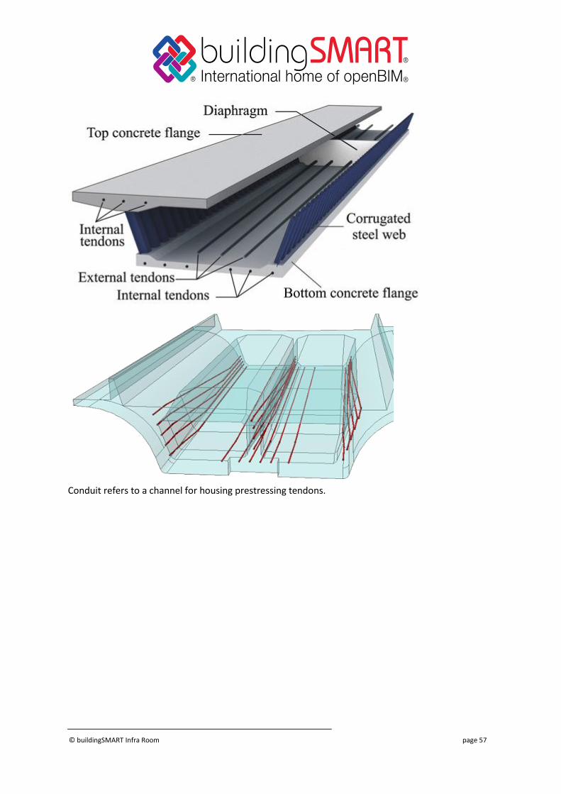
© buildingSMART Infra Room page 57
Conduit refers to a channel for housing prestressing tendons.
© buildingSMART Infra Room page 58
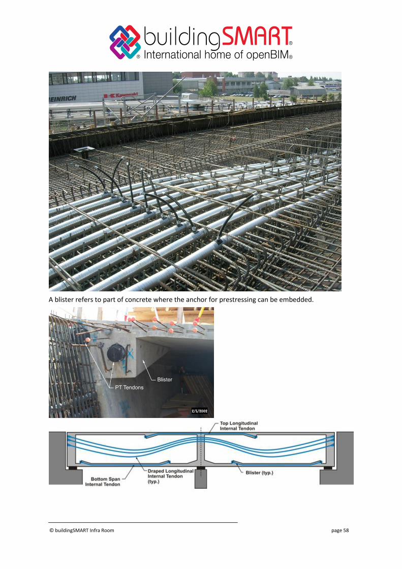
A blister refers to part of concrete where the anchor for prestressing can be embedded.
© buildingSMART Infra Room page 59
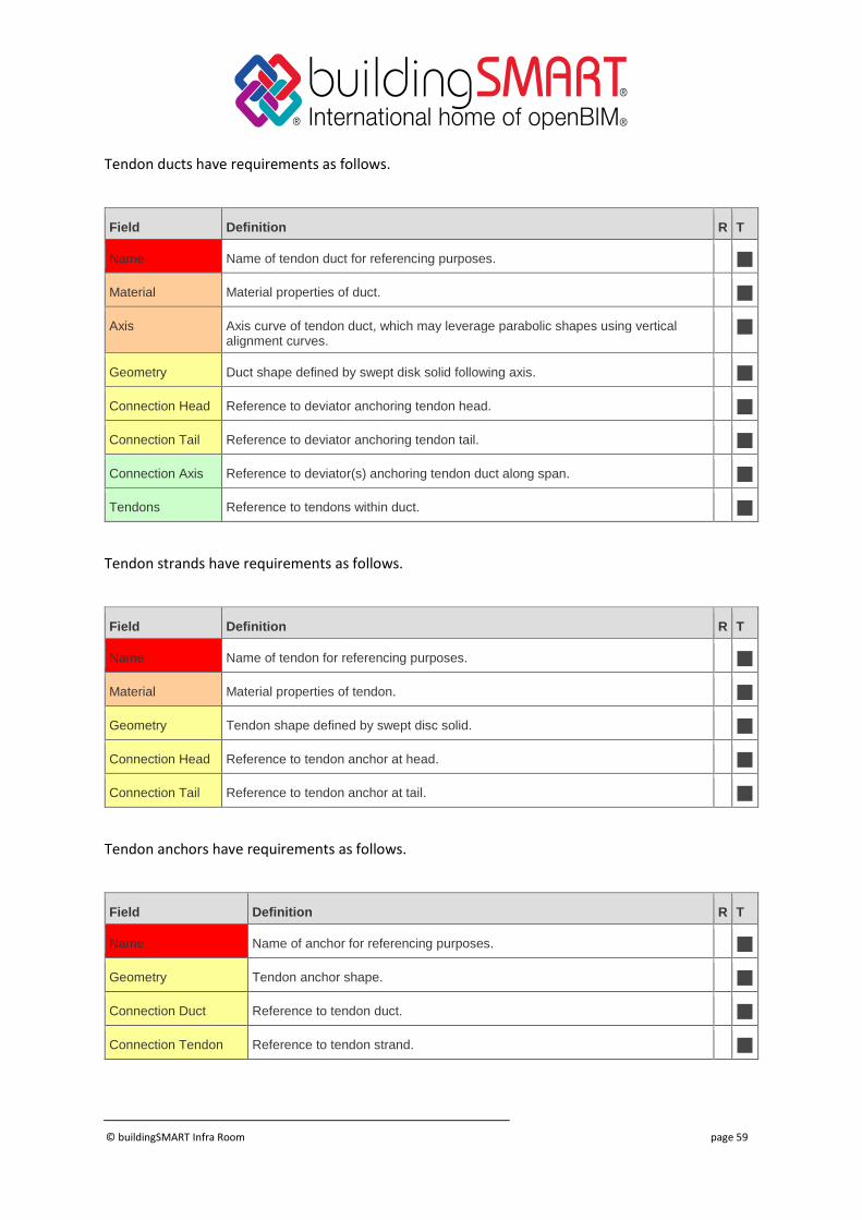
Tendon ducts have requirements as follows.
Field Definition R T
Name Name of tendon duct for referencing purposes.
Material Material properties of duct.
Axis Axis curve of tendon duct, which may leverage parabolic shapes using vertical alignment curves.
Geometry Duct shape defined by swept disk solid following axis.
Connection Head Reference to deviator anchoring tendon head.
Connection Tail Reference to deviator anchoring tendon tail.
Connection Axis Reference to deviator(s) anchoring tendon duct along span.
Tendons Reference to tendons within duct.
Tendon strands have requirements as follows.
Field Definition R T
Name Name of tendon for referencing purposes.
Material Material properties of tendon.
Geometry Tendon shape defined by swept disc solid.
Connection Head Reference to tendon anchor at head.
Connection Tail Reference to tendon anchor at tail.
Tendon anchors have requirements as follows.
Field Definition R T
Name Name of anchor for referencing purposes.
Geometry Tendon anchor shape.
Connection Duct Reference to tendon duct.
Connection Tendon Reference to tendon strand.
© buildingSMART Infra Room page 60
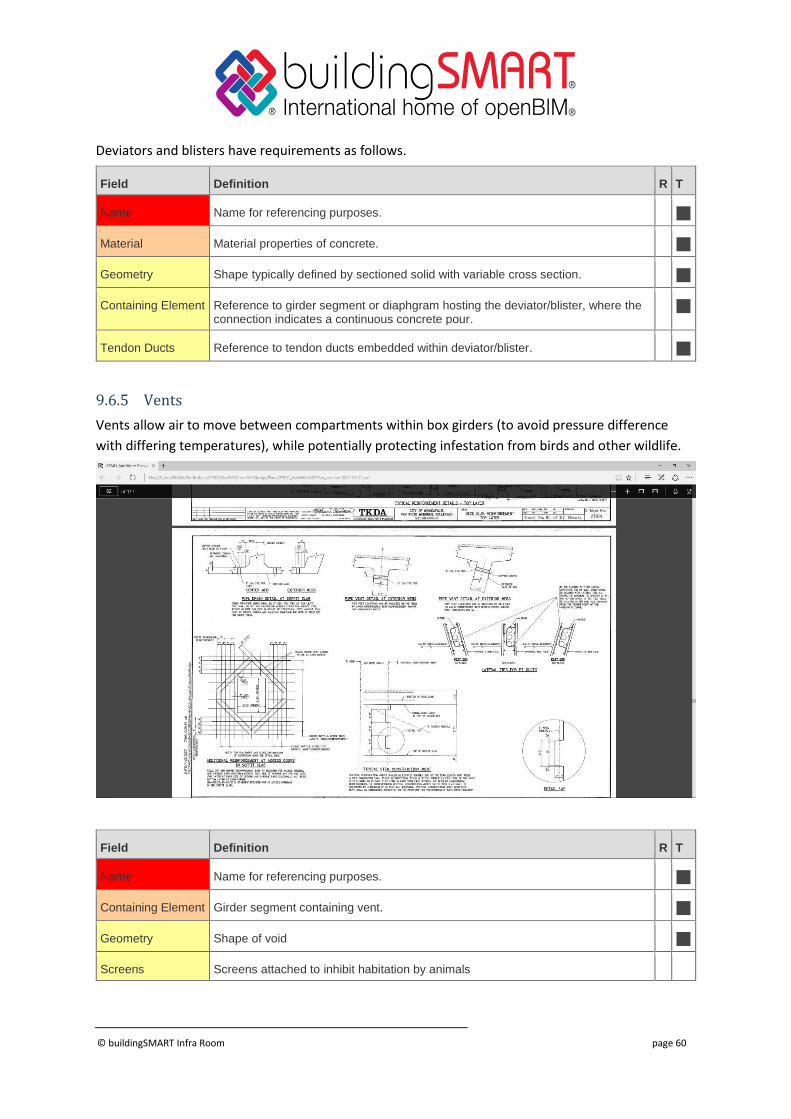
Deviators and blisters have requirements as follows.
Field Definition R T
Name Name for referencing purposes.
Material Material properties of concrete.
Geometry Shape typically defined by sectioned solid with variable cross section.
Containing Element Reference to girder segment or diaphgram hosting the deviator/blister, where the connection indicates a continuous concrete pour.
Tendon Ducts Reference to tendon ducts embedded within deviator/blister.
9.6.5 Vents
Vents allow air to move between compartments within box girders (to avoid pressure difference
with differing temperatures), while potentially protecting infestation from birds and other wildlife.
Field Definition R T
Name Name for referencing purposes.
Containing Element Girder segment containing vent.
Geometry Shape of void
Screens Screens attached to inhibit habitation by animals
© buildingSMART Infra Room page 61
9.6.6 Access Panels
For box girder bridges with enclosed compartments, access panels allow for inspection and
maintenance of components, while restricting access from unauthorized persons or wildlife.
Field Definition R T
Name Name for referencing purposes.
Containing Element Girder segment containing access panel.
Geometry Shape of access panel
9.7 Drainage
Drainage elements include all elements used for carrying stormwater away from the bridge
structure.
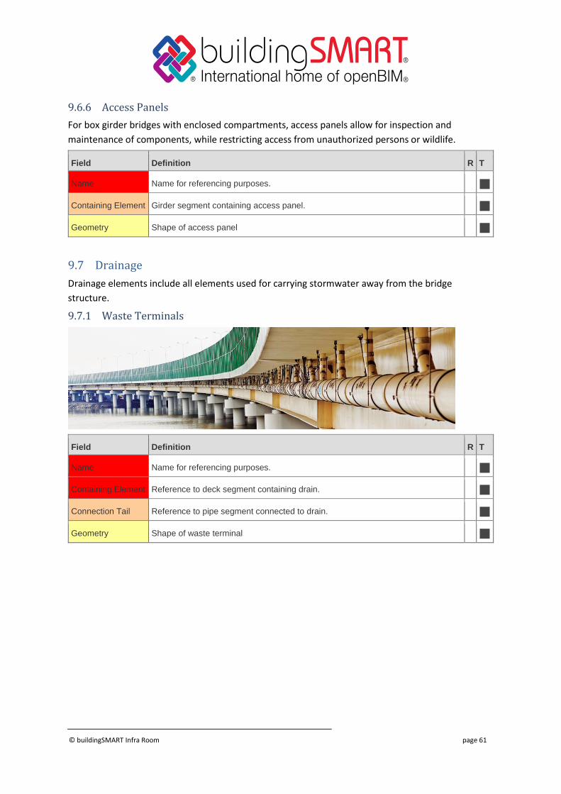
9.7.1 Waste Terminals
Field Definition R T
Name Name for referencing purposes.
Containing Element Reference to deck segment containing drain.
Connection Tail Reference to pipe segment connected to drain.
Geometry Shape of waste terminal
© buildingSMART Infra Room page 62
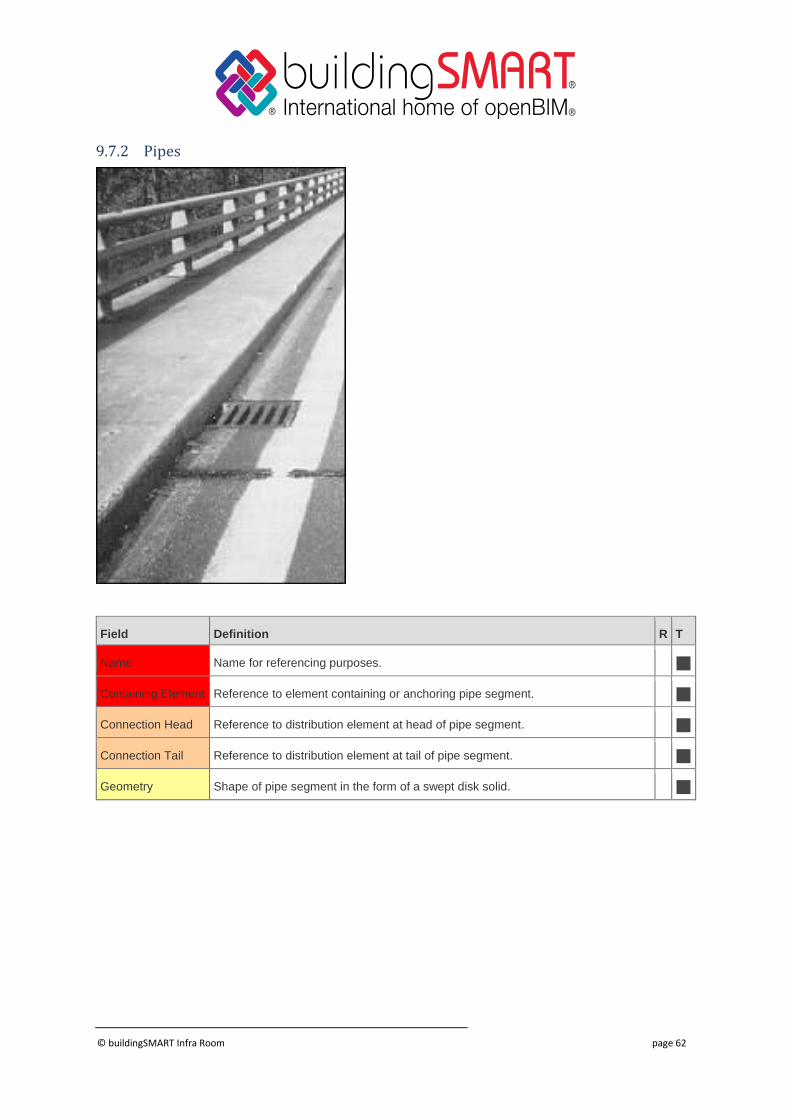
9.7.2 Pipes
Field Definition R T
Name Name for referencing purposes.
Containing Element Reference to element containing or anchoring pipe segment.
Connection Head Reference to distribution element at head of pipe segment.
Connection Tail Reference to distribution element at tail of pipe segment.
Geometry Shape of pipe segment in the form of a swept disk solid.
© buildingSMART Infra Room page 63
9.8 Electrical
Electrical elements are comprised of fixtures, wiring, conduit, and junctions that carry electrical
power, communications, or other electric signals.
While electrical requirements are often captured separately from bridge structures, embedded
elements (e.g. conduit) must be captured for concrete construction.
9.8.1 Junction Box
Field Definition R T
Name Name of the junction box for referencing purposes as would be found on construction plans.
Embedding Element
If embedded in concrete, indicates the element containing the junction box.
Anchoring Element If attached to a surface, indicates the element anchoring the junction box.
Body Geometry Geometry of junction box.
Conduit Conduit connected to junction box.
© buildingSMART Infra Room page 64
9.8.2 Conduit
Conduit is defined as a segment connecting one electrical device (or junction box) to another,
following a linear path, and potentially embedded within another element (e.g. parapet wall).
Field Definition R T
Name Name of the conduit for referencing purposes as would be found on construction plans.
Embedding Element
If embedded in concrete, indicates the element containing the conduit.
Anchoring Element If attached to a surface, indicates the element anchoring the conduit.
Body Geometry Geometry of conduit, in the form of a swept disk solid.
Connection Head Connection to junction box at head.
Connection Tail Connection to junction box at tail.
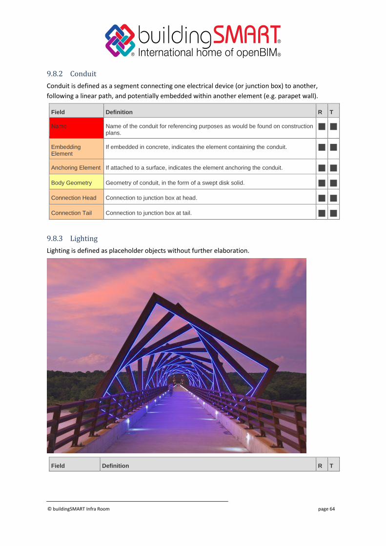
9.8.3 Lighting
Lighting is defined as placeholder objects without further elaboration.
Field Definition R T

© buildingSMART Infra Room page 65
Name Name of the light fixture for referencing purposes as would be found on construction plans.
Placement Placement of light fixture.
Anchoring Element
Reference to physical element anchoring light fixture, such as a mounting plate.
Conduit Reference to conduit for which wiring is connected.
© buildingSMART Infra Room page 66
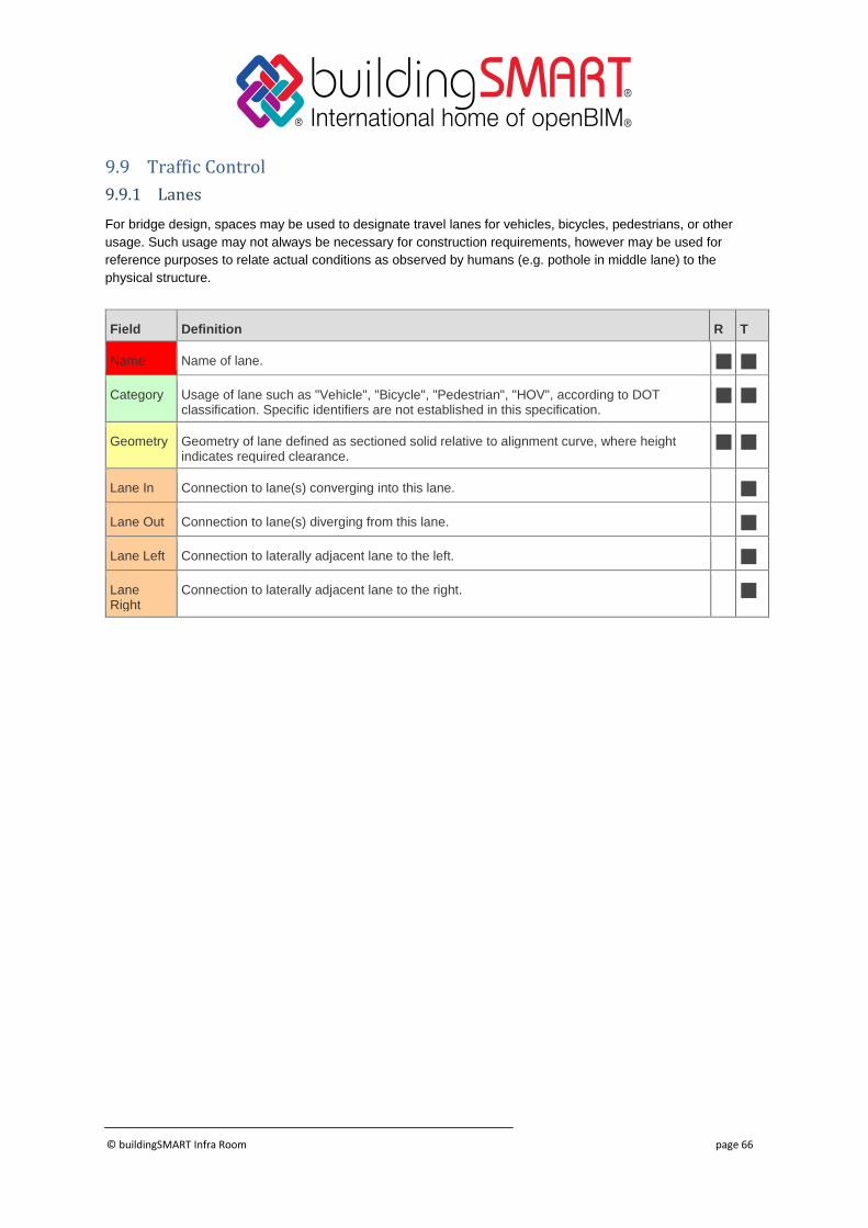
9.9 Traffic Control
9.9.1 Lanes
For bridge design, spaces may be used to designate travel lanes for vehicles, bicycles, pedestrians, or other
usage. Such usage may not always be necessary for construction requirements, however may be used for
reference purposes to relate actual conditions as observed by humans (e.g. pothole in middle lane) to the
physical structure.
Field Definition R T
Name Name of lane.
Category Usage of lane such as "Vehicle", "Bicycle", "Pedestrian", "HOV", according to DOT classification. Specific identifiers are not established in this specification.
Geometry Geometry of lane defined as sectioned solid relative to alignment curve, where height indicates required clearance.
Lane In Connection to lane(s) converging into this lane.
Lane Out Connection to lane(s) diverging from this lane.
Lane Left Connection to laterally adjacent lane to the left.
Lane Right
Connection to laterally adjacent lane to the right.

© buildingSMART Infra Room page 67
9.9.2 Signs
Traffic signs include static signage, signals, and displays (using LEDs or video displays). It is
anticipated that sign definitions (and “road furniture” in general) provide for placement and
dimensions, along with specification of colors, reflective materials, graphics and lettering. Such
definition is outside the scope of this project; it is anticipated that the IFC-Road extension will
capture such detail.
© buildingSMART Infra Room page 68
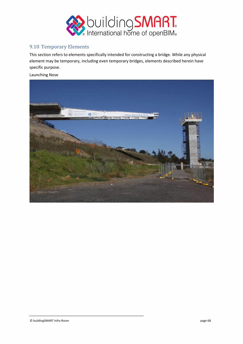
9.10 Temporary Elements
This section refers to elements specifically intended for constructing a bridge. While any physical
element may be temporary, including even temporary bridges, elements described herein have
specific purpose.
Launching Nose

© buildingSMART Infra Room page 69
9.10.1 Launching Gantry
9.10.2 Staying Mast
© buildingSMART Infra Room page 70
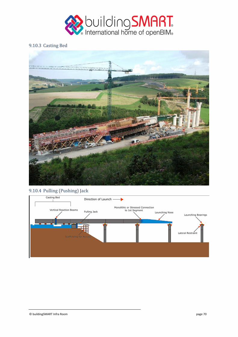
9.10.3 Casting Bed
9.10.4 Pulling (Pushing) Jack

© buildingSMART Infra Room page 71
9.10.5 Launching Bearings

© buildingSMART Infra Room page 72
10 Next Steps In the next Work Package (WP2), the project team will identify the object types and attributes
that are required for describing bridges from a semantic viewpoint in a way that is satisfying
the use cases identified in WP1. To this end, a bridge taxonomy is created defining all
necessary terms used in the context of bridge engineering. On the basis of the taxonomy, a
mapping of the identified concepts to existing or new IFC entities is defined. This allows to
specify new data structures (where necessary) as well as the Model View Definitions as
discussed above.