Embed Size (px)
Citation preview
Highlights Self-healing property High DV / DT Low ESR Low loss polypropylene dielectric Reference standard-IEC 61071 Flame retardant UL94 - V0, ROHS compliant
ConstructionExtended foil electrodes with metallised polypropylene dielectric internal series connection
ApplicationsThese capacitors are used in high voltage, high current and high pulse applications such as: IGBT protection circuits Snubber networks Energy conversion and control in power electronics Protection circuits in SMPS
KPF
Polypropylene as dielectric
Aluminium foil as electrodes
End spray
Metallised polypropylene film
1
Temperature
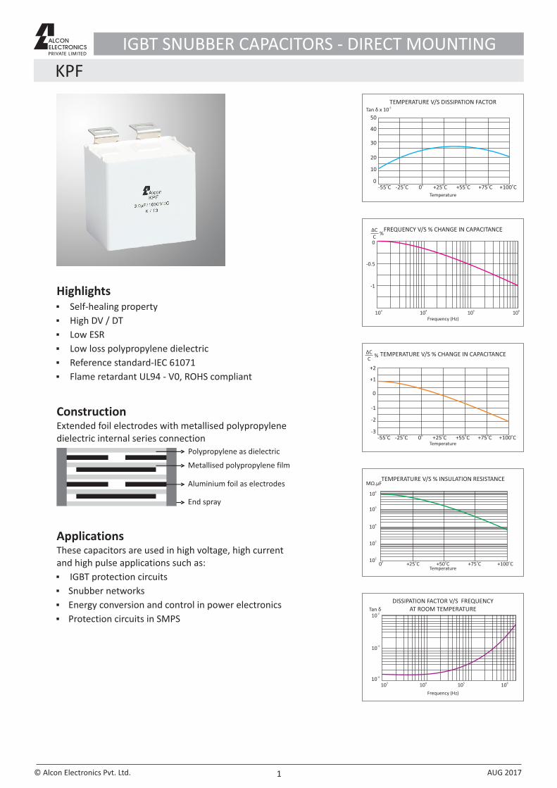
TEMPERATURE V/S DISSIPATION FACTOR-5
Tan δ x 10
50
40
30
20
10
0o-55 C o-25 C o0 o+25 C o+55 C o+75 C o+100 C
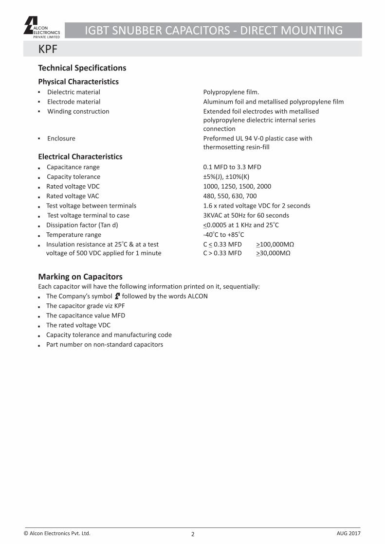
FREQUENCY V/S % CHANGE IN CAPACITANCEΔCC
%
Frequency (Hz)
0
-0.5
-1
310
410
510 610
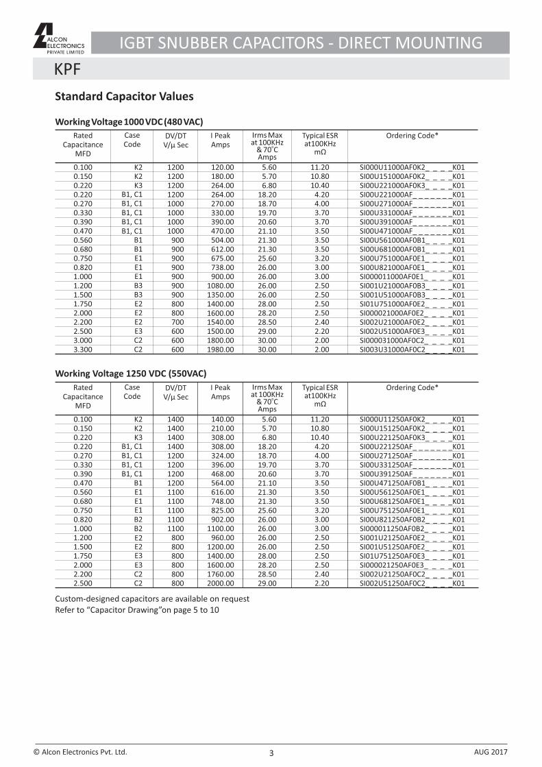
ΔCC
% TEMPERATURE V/S % CHANGE IN CAPACITANCE
+2
+1
0
-1
-2
-3o-55 C o-25 C o0 o+25 C o+55 C o+75 C o+100 C
Temperature
TEMPERATURE V/S % INSULATION RESISTANCEMΩ.µF
Temperature
610
510
410
310
210 o0
o+25 C
o+50 C
o+75 C
o+100 C
DISSIPATION FACTOR V/S FREQUENCY AT ROOM TEMPERATURE Tan δ
Frequency (Hz)
310410
510 610
-210
-310
-410
IGBT SNUBBER CAPACITORS - DIRECT MOUNTING
© Alcon Electronics Pvt. Ltd. AUG 2017
KPF
2
Technical Specifications
Physical Characteristics Dielectric material Polypropylene film. Electrode material Aluminum foil and metallised polypropylene film Winding construction Extended foil electrodes with metallised polypropylene dielectric internal series connection Enclosure Preformed UL 94 V-0 plastic case with thermosetting resin-fill
Electrical Characteristics Capacitance range 0.1 MFD to 3.3 MFD
Capacity tolerance ±5%(J), ±10%(K)
Rated voltage VDC 1000, 1250, 1500, 2000
Rated voltage VAC 480, 550, 630, 700
Test voltage between terminals 1.6 x rated voltage VDC for 2 seconds
Test voltage terminal to case 3KVAC at 50Hz for 60 secondso
Dissipation factor (Tan d) <0.0005 at 1 KHz and 25 Co o
Temperature range -40 C to +85 Co
Insulation resistance at 25 C & at a test C < 0.33 MFD >100,000MΩ voltage of 500 VDC applied for 1 minute C > 0.33 MFD >30,000MΩ
Marking on CapacitorsEach capacitor will have the following information printed on it, sequentially:
The Company’s symbol followed by the words ALCON
The capacitor grade viz KPF
The capacitance value MFD
The rated voltage VDC
Capacity tolerance and manufacturing code
Part number on non-standard capacitors
IGBT SNUBBER CAPACITORS - DIRECT MOUNTING
© Alcon Electronics Pvt. Ltd. AUG 2017
Standard Capacitor Values
Rated Capacitance
MFD
Case Code
DV/DT V/µ Sec
I PeakAmps
Typical ESR at100KHz
mΩ
Ordering Code*Irms Max at 100KHz
o& 70 CAmps
0.1000.1500.2200.2200.2700.3300.3900.4700.5600.6800.7500.8201.0001.2001.5001.7502.0002.2002.5003.0003.300
12001200120012001000100010001000
900900900900900900900800800700600600600
120.00180.00264.00264.00270.00330.00390.00470.00504.00612.00675.00738.00900.00
1080.001350.001400.001600.001540.001500.001800.001980.00
5.605.706.80
18.2018.7019.7020.6021.1021.3021.3025.6026.0026.0026.0026.0028.0028.2028.5029.0030.0030.00
11.2010.8010.40
4.204.003.703.703.503.503.503.203.003.002.502.502.502.502.402.202.002.00
K2K2K3
B1, C1B1, C1
B1 B1E1E1E1B3B3E2E2E2E3C2C2
B1, C1B1, C1B1, C1
Working Voltage 1000 VDC (480 VAC)
Working Voltage 1250 VDC (550VAC)
Rated Capacitance
MFD
Case Code
DV/DT V/µ Sec
I PeakAmps
Typical ESRat100KHz
mΩ
Ordering Code*
0.1000.1500.2200.2200.2700.3300.3900.4700.5600.6800.7500.8201.0001.2001.5001.7502.0002.2002.500
1400140014001400120012001200
1200 1100
1100110011001100
800800800800800800
140.00210.00308.00308.00324.00396.00468.00564.00616.00748.00825.00902.00
1100.00960.00
1200.001400.001600.001760.002000.00
11.2010.8010.40
4.204.003.703.703.503.503.503.20
3.002.502.502.502.502.402.20
3.00
5.605.706.80
18.2018.7019.7020.6021.1021.3021.3025.6026.0026.0026.0026.0028.0028.2028.5029.00
K2K2K3
B1, C1
B1E1E1E1B2B2E2E2
E3C2C2
B1, C1B1, C1B1, C1
E3
Irms Max at 100KHz
o& 70 CAmps
KPF
3
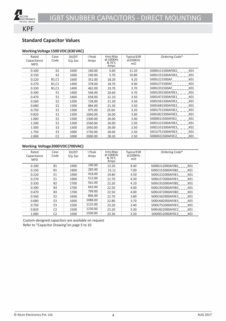
Custom-designed capacitors are available on requestRefer to “Capacitor Drawing”on page 5 to 10
IGBT SNUBBER CAPACITORS - DIRECT MOUNTING
© Alcon Electronics Pvt. Ltd. AUG 2017
SI000U11000AF0K2_ _ _ _K01SI00U151000AF0K2_ _ _ _K01SI00U221000AF0K3_ _ _ _K01SI00U221000AF_ _ _ _ _ _ _K01SI00U271000AF_ _ _ _ _ _ _K01SI00U331000AF_ _ _ _ _ _ _K01SI00U391000AF_ _ _ _ _ _ _K01SI00U471000AF_ _ _ _ _ _ _K01SI00U561000AF0B1_ _ _ _K01SI00U681000AF0B1_ _ _ _K01SI00U751000AF0E1_ _ _ _K01SI00U821000AF0E1_ _ _ _K01SI000011000AF0E1_ _ _ _K01SI001U21000AF0B3_ _ _ _K01SI001U51000AF0B3_ _ _ _K01SI01U751000AF0E2_ _ _ _K01SI000021000AF0E2_ _ _ _K01SI002U21000AF0E2_ _ _ _K01SI002U51000AF0E3_ _ _ _K01SI000031000AF0C2_ _ _ _K01SI003U31000AF0C2_ _ _ _K01
SI000U11250AF0K2_ _ _ _K01SI00U151250AF0K2_ _ _ _K01SI00U221250AF0K3_ _ _ _K01SI00U221250AF_ _ _ _ _ _ _K01SI00U271250AF_ _ _ _ _ _ _K01SI00U331250AF_ _ _ _ _ _ _K01SI00U391250AF_ _ _ _ _ _ _K01SI00U471250AF0B1_ _ _ _K01SI00U561250AF0E1_ _ _ _K01SI00U681250AF0E1_ _ _ _K01SI00U751250AF0E1_ _ _ _K01SI00U821250AF0B2_ _ _ _K01SI000011250AF0B2_ _ _ _K01SI001U21250AF0E2_ _ _ _K01SI001U51250AF0E2_ _ _ _K01SI01U751250AF0E3_ _ _ _K01SI000021250AF0E3_ _ _ _K01SI002U21250AF0C2_ _ _ _K01SI002U51250AF0C2_ _ _ _K01
Standard Capacitor Values
0.100
0.150
0.220
0.270
0.330
0.390
0.470
0.560
0.680
0.750
0.820
1.000
1.200
1.500
1.750
2.000
1600
1600
1600
1400
1400
1400
1300
1300
1300
1300
1300
1300
1000
1000
1400
1300
5.60
5.70
18.20
18.70
19.70
20.60
21.10
21.30
21.30
25.60
26.00
26.00
26.00
26.00
28.00
28.20
11.20
10.80
4.20
4.00
3.70
3.70
3.50
3.50
3.50
3.20
3.00
3.00
2.50
2.50
2.50
2.50
K2
K2
B1,C1
E1
E2
E2
E2
E2
E2
E3
E1
E2
E3
C2
B1,C1
B1,C1
160.00
240.00
352.00
378.00
462.00
546.00
658.00
728.00
884.00
975.00
1066.00
1300.00
1560.00
1950.00
1750.00
2000.00
190.00
285.00
418.00
513.00
561.00
663.00
799.00
896.00
1088.00
1125.00
1230.00
1500.00
Working Voltage 2000 VDC (700VAC)
Rated Capacitance
MFD
Case Code
DV/DT V/µ Sec
I PeakAmps
Typical ESRat100KHz
mΩ
Ordering Code*
0.100
0.150
0.220
0.270
0.330
0.390
0.470
0.560
0.680
0.750
0.820
1.000
B1
B1
E1
E1
B2
B3
B3
E2
E3
E3
C2
C2
1900
1900
1900
1900
1700
1700
1700
1600
1600
1500
1500
1500
13.20
15.11
19.80
21.70
22.20
22.50
22.50
22.70
22.80
23.20
23.20
23.30
8.40
7.00
4.50
4.30
4.10
4.00
4.00
3.80
3.70
3.40
3.30
3.20
Irms Max at 100KHz
o& 70 CAmps
Rated Capacitance
MFD
Case Code
DV/DT V/µ Sec
I PeakAmps
Typical ESR at100KHz
mΩ
Ordering Code*Irms Max at 100KHz
o& 70 CAmps
Working Voltage 1500 VDC (630 VAC)
KPF
4
Custom-designed capacitors are available on requestRefer to “Capacitor Drawing”on page 5 to 10
IGBT SNUBBER CAPACITORS - DIRECT MOUNTING
© Alcon Electronics Pvt. Ltd. AUG 2017
SI000U11500AF0K2_ _ _ _K01
SI00U151500AF0K2_ _ _ _K01
SI00U221500AF_ _ _ _ _ _ _K01
SI00U271500AF_ _ _ _ _ _ _K01
SI00U331500AF_ _ _ _ _ _ _K01
SI00U391500AF0E1_ _ _ _K01
SI00U471500AF0E1_ _ _ _K01
SI00U561500AF0E2_ _ _ _K01
SI00U681500AF0E2_ _ _ _K01
SI00U751500AF0E2_ _ _ _K01
SI00U821500AF0E2_ _ _ _K01
SI000011500AF0E2_ _ _ _K01
SI001U21500AF0E2_ _ _ _K01
SI001U51500AF0E3_ _ _ _K01
SI01U751500AF0E3_ _ _ _K01
SI000021500AF0C2_ _ _ _K01
SI000U12000AF0B1_ _ _ _K01
SI00U152000AF0B1_ _ _ _K01
SI00U222000AF0E1_ _ _ _K01
SI00U272000AF0E1_ _ _ _K01
SI00U332000AF0B2_ _ _ _K01
SI00U392000AF0B3_ _ _ _K01
SI00U472000AF0B3_ _ _ _K01
SI00U562000AF0E2_ _ _ _K01
SI00U682000AF0E3_ _ _ _K01
SI00U752000AF0E3_ _ _ _K01
SI00U822000AF0C2_ _ _ _K01
SI000012000AF0C2_ _ _ _K01
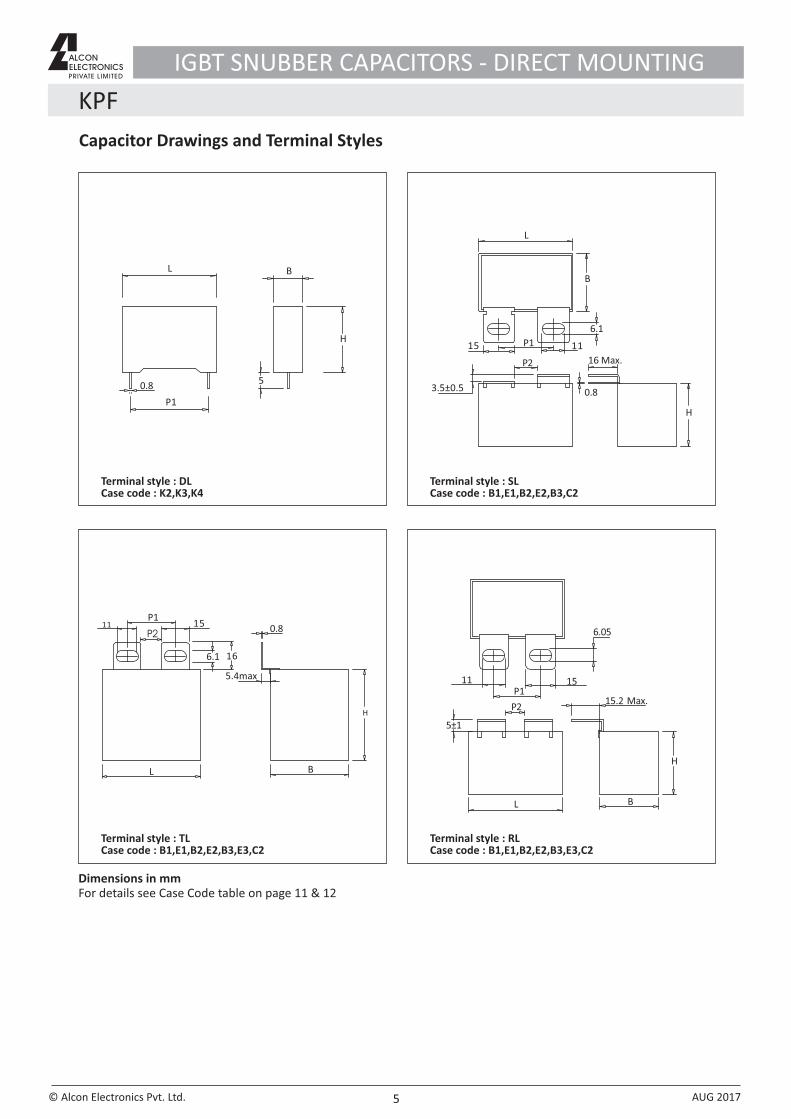
Capacitor Drawings and Terminal Styles
H
P1
L B
50.8
Terminal style : DL Case code : K2,K3,K4
Terminal style : SL Case code : B1,E1,B2,E2,B3,C2
Terminal style : TLCase code : B1,E1,B2,E2,B3,E3,C2
Terminal style : RL Case code : B1,E1,B2,E2,B3,E3,C2
166.1
L
H
B
P2
P111 0.815
P2
P1
L
11 15
B
H
15.2 Max.
6.05
3.5±0.5
P2
P1
L
15
6.1
11
H
16 Max.
0.8
B
KPF
5
Dimensions in mmFor details see Case Code table on page 11 & 12
IGBT SNUBBER CAPACITORS - DIRECT MOUNTING
5.4max
5±1
© Alcon Electronics Pvt. Ltd. AUG 2017
L
57 Max.
P2
11
5
6
P1
H
B
1
0.8
17.5 Max10
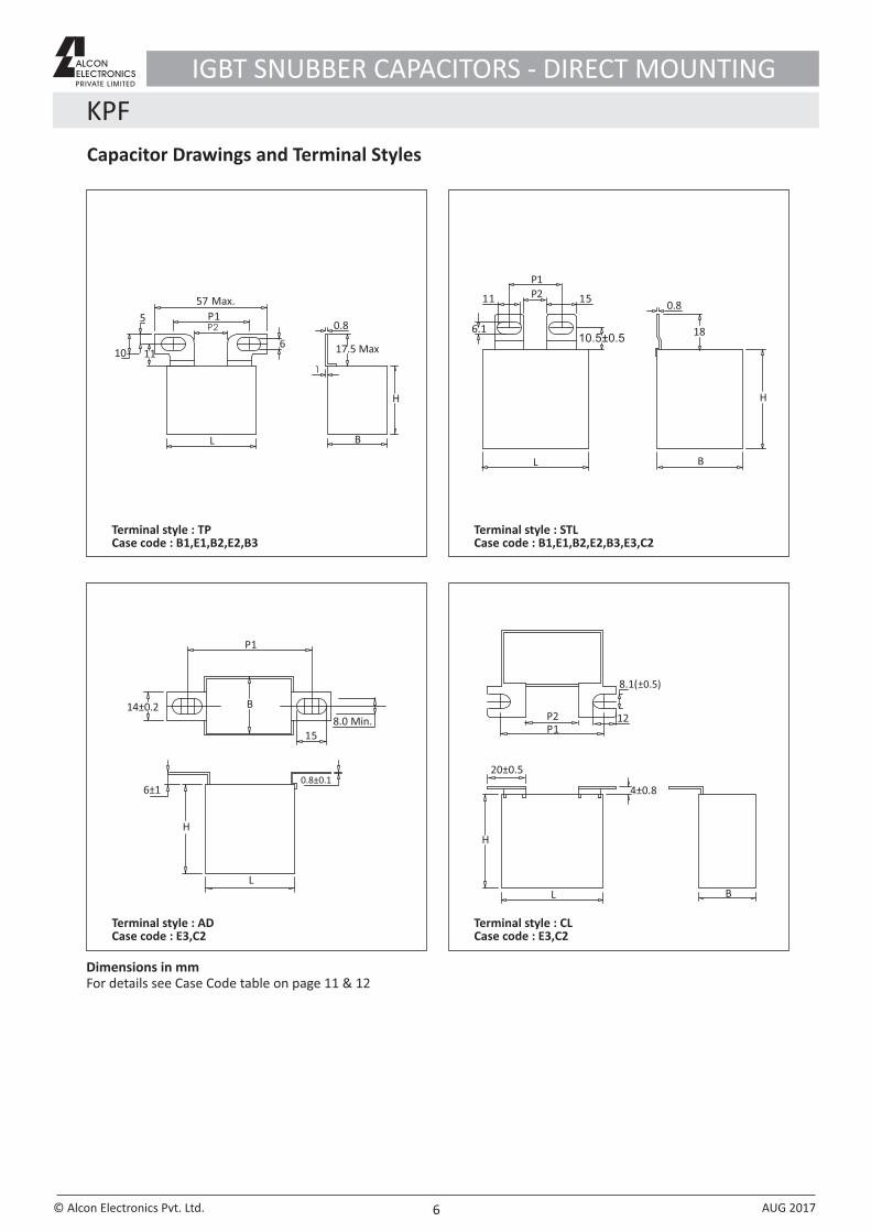
Terminal style : TPCase code : B1,E1,B2,E2,B3
H
L B
P1
11
6.1
P20.8
18
15
10.5±0.5
Terminal style : STL Case code : B1,E1,B2,E2,B3,E3,C2
15
6±10.8±0.1
L
H
14±0.2
P1
8.0 Min.
B
Terminal style : ADCase code : E3,C2
L B
H
20±0.5
4±0.8
12
8.1(±0.5)
P1P2
Terminal style : CL Case code : E3,C2
KPF
6
Capacitor Drawings and Terminal Styles
Dimensions in mmFor details see Case Code table on page 11 & 12
IGBT SNUBBER CAPACITORS - DIRECT MOUNTING
© Alcon Electronics Pvt. Ltd. AUG 2017
KPF
7
H 36 Max
1115
3.5±0.5
9
6.05
B
7
P1= 3144
0.8
BL
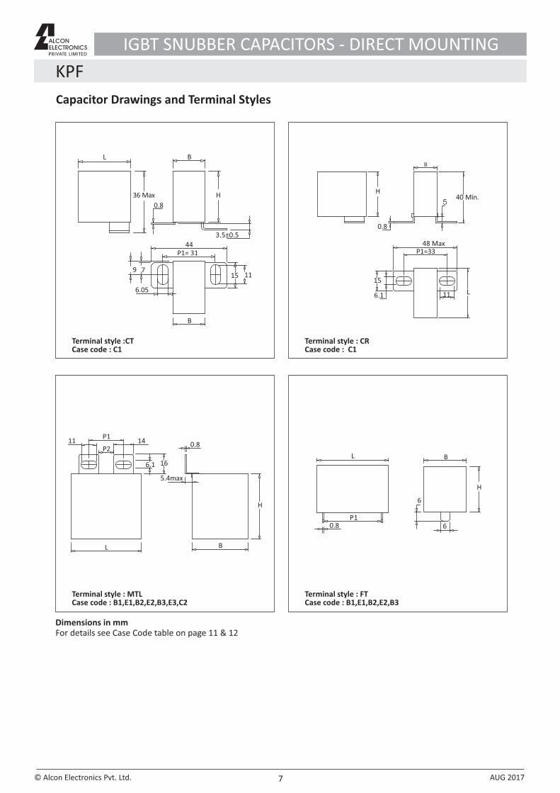
Terminal style :CTCase code : C1
11
48 MaxP1=33
40 Min.
L
H
5
0.8
6.1
15
B
Terminal style : CR Case code : C1
BL
14 0.811P1
P2
6.1 16
H
Terminal style : MTLCase code : B1,E1,B2,E2,B3,E3,C2
B
6
6
L
P1
H
0.8
Terminal style : FT Case code : B1,E1,B2,E2,B3
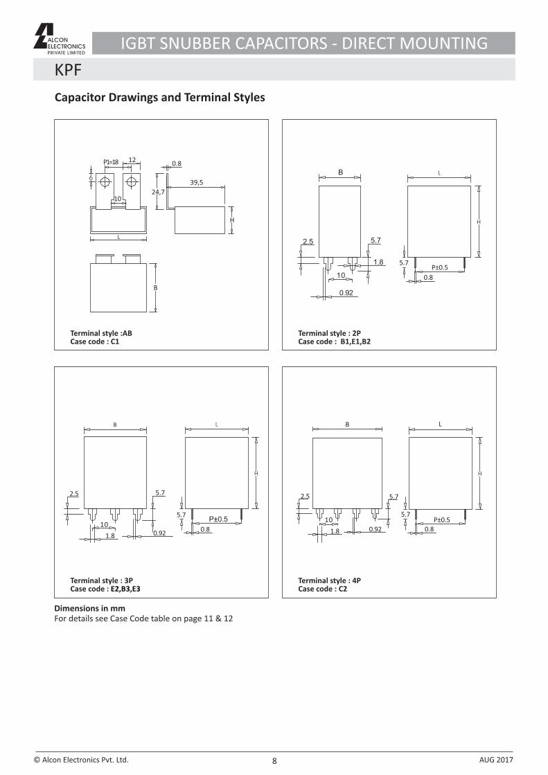
Capacitor Drawings and Terminal Styles
Dimensions in mmFor details see Case Code table on page 11 & 12
IGBT SNUBBER CAPACITORS - DIRECT MOUNTING
5.4max
© Alcon Electronics Pvt. Ltd. AUG 2017
KPF
8
6
P1=18 12
24,7
39,5
10
L
B
H
0.8B
2.5
10
0.92
1.8
5.7
5.7P±0.5
0.8
Terminal style : 2P Case code : B1,E1,B2
Terminal style : 4P Case code : C2
B
1.8
10
2.5
0.92
5.7
5.7
0.8
P±0.5
L
5.7
1.8
10
2.5
0.92
B
P±0.5
0.8
5.7
Terminal style :ABCase code : C1
Terminal style : 3PCase code : E2,B3,E3
Capacitor Drawings and Terminal Styles
Dimensions in mmFor details see Case Code table on page 11 & 12
IGBT SNUBBER CAPACITORS - DIRECT MOUNTING
© Alcon Electronics Pvt. Ltd. AUG 2017
KPF
9
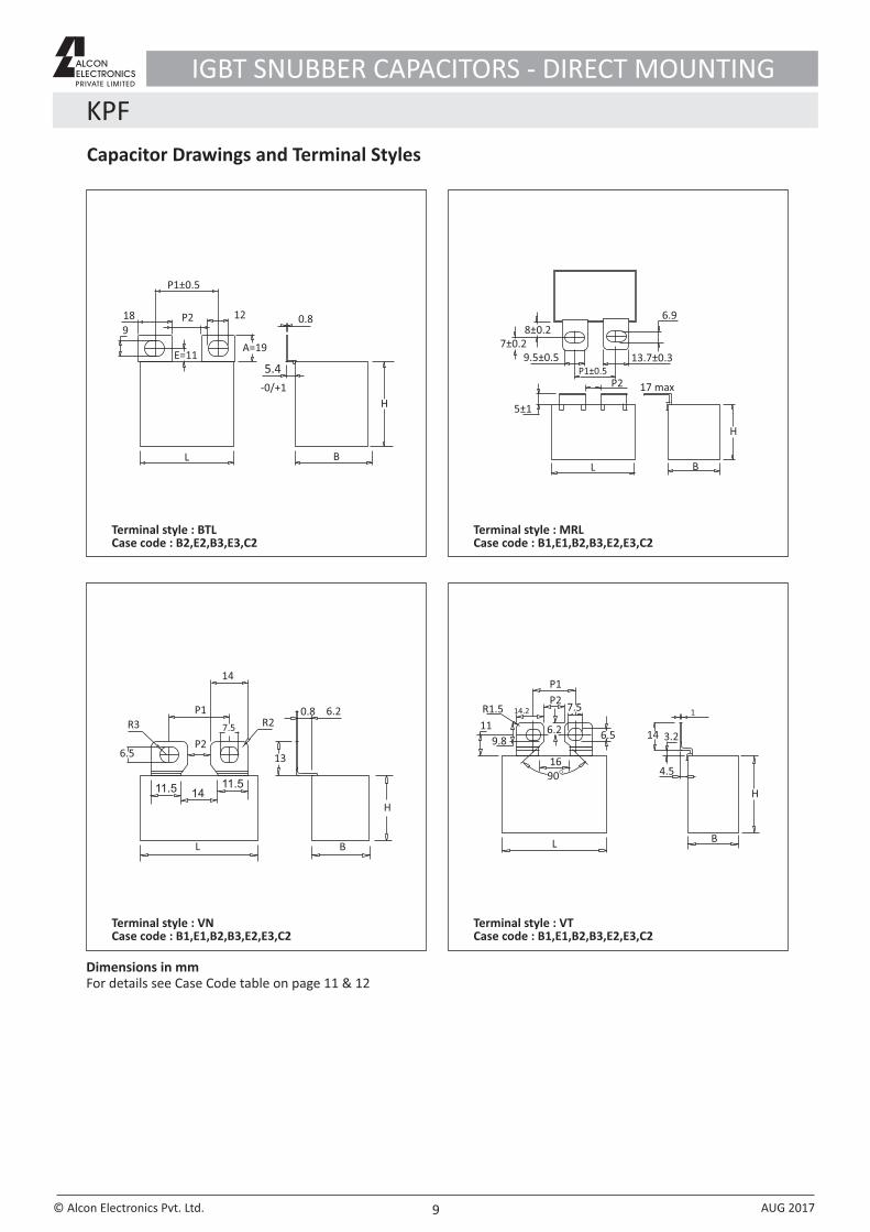
P1±0.5
12P218
9
E=11
L B
A=19
5.4
0.8
H
13.7±0.39.5±0.5P1±0.5
7±0.28±0.2
5±1
P2
6.9
L B
H
17 max
11.5 1411.5
6.5P2
R3P1
7.5
L B
H
13
R20.8 6.2
14
L
H
B
16
6.5
7.5P2
P1
6.2
14.2R1.5
11
9.8
O90
3.214
1
4.5
Terminal style : BTLCase code : B2,E2,B3,E3,C2
Terminal style : MRL Case code : B1,E1,B2,B3,E2,E3,C2
Terminal style : VNCase code : B1,E1,B2,B3,E2,E3,C2
Terminal style : VTCase code : B1,E1,B2,B3,E2,E3,C2
Capacitor Drawings and Terminal Styles
Dimensions in mmFor details see Case Code table on page 11 & 12
IGBT SNUBBER CAPACITORS - DIRECT MOUNTING
-0/+1
© Alcon Electronics Pvt. Ltd. AUG 2017
KPF
10
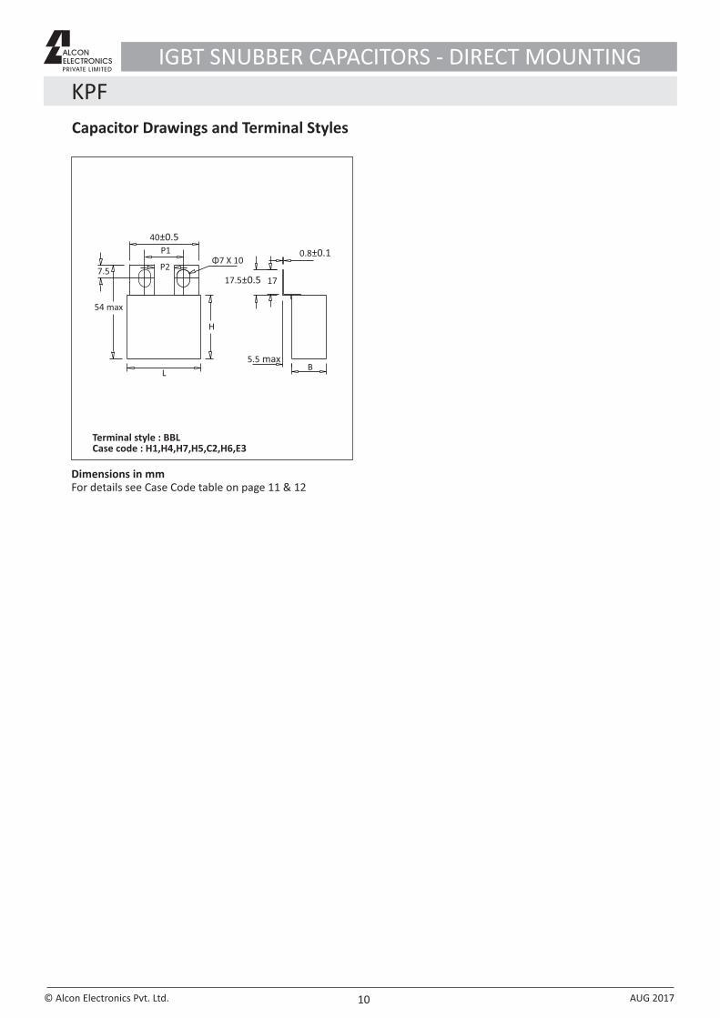
Capacitor Drawings and Terminal Styles
Dimensions in mmFor details see Case Code table on page 11 & 12
IGBT SNUBBER CAPACITORS - DIRECT MOUNTING
Terminal style : BBLCase code : H1,H4,H7,H5,C2,H6,E3
40±0.5P1
P27.5
54 max
H
17.5±0.5 17
0.8±0.1
B5.5 max
Φ7 X 10
L
© Alcon Electronics Pvt. Ltd. AUG 2017
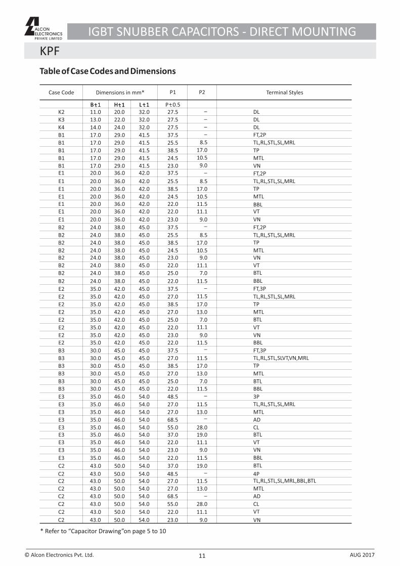
Table of Case Codes and Dimensions
KPF
11
Dimensions in mm* P2P1Case Code Terminal Styles
B1
B1E1
E1
E1
B2
B2
B2
K2
K3
K4
B1
E1
B1
B2
25.5
23.037.5
25.5
24.5
37.5
38.5
24.5
27.5
27.5
27.5
37.5
38.5
38.5
25.5
17.0
17.020.0
20.0
20.0
24.0
24.0
24.0
11.0
13.0
14.0
17.0
20.0
17.0
24.0
29.0
29.036.0
36.0
36.0
38.0
38.0
38.0
20.0
22.0
24.0
29.0
36.0
29.0
38.0
41.5
41.542.0
42.0
42.0
45.0
45.0
45.0
32.0
32.0
32.0
41.5
42.0
41.5
45.0
8.5
9.0
8.5
17.0
17.0
_
_
_
_
_
10.5
8.5
17.0
_
10.5
B+- 1 H+- 1 +-L 1B+- 1 H+- 1 +-L 1 P+- 0.5
B1 24.517.0 29.0 41.5 10.5
E1E1
E1
22.022.0
23.0
20.020.0
20.0
36.036.0
36.0
42.042.0
42.0
11.1
9.0
11.5
B2
B2
B2
23.0
25.0
22.0
24.0
24.0
24.0
38.0
38.0
38.0
45.0
45.0
45.0 11.1
7.0
9.0
C2
E2
E3
E3
E2
E2
B3
B3
E3
C2
B3
E3
E2
B3
E3
C2
C2
C2
37.5
27.0
27.0
27.0
38.5
37.5
27.0
55.0
48.5
27.0
68.5
27.0
38.5
48.5
27.027.0
68.5
55.0
43.0
35.0
35.0
35.0
35.0
35.0
30.0
30.0
35.0
43.0
30.0
35.0
35.0
30.0
35.0
43.0
43.0
43.0
50.0
42.0
46.0
46.0
42.0
42.0
45.0
45.0
46.0
50.0
45.0
46.0
42.0
45.0
46.0
50.0
50.0
50.0
54.0
45.0
54.0
54.0
45.0
45.0
45.0
45.0
54.0
54.0
45.0
54.0
45.0
45.0
54.0
54.0
54.0
54.0
E3
C2
37.035.0 46.0 54.0
37.043.0 50.0 54.0
13.0
11.5
13.0
28.0
11.5
17.0
11.5
13.0
17.0
28.0
11.5
13.0
_
_
_
_
_
_
19.0
19.0
E2
E2
E2
25.0
22.0
23.0
35.0
35.0
35.0
42.0
42.0
42.0
45.0
45.0
45.0
11.1
9.0
7.0
B3 25.030.0 45.0 45.0
E3
E3
23.0
22.0
35.0
35.0
46.0
46.0
54.0
54.0
9.0
11.1
C2 23.043.0 50.0 54.0
C2 22.043.0 50.0 54.0 11.1
7.0
9.0
B2 22.024.0 38.0 45.0 11.5
E2 22.035.0 42.0 45.0 11.5
B3 22.030.0 45.0 45.0 11.5
E3 22.035.0 46.0 54.0 11.5
TP
MTL
TL,RL,STL,SL,MRL
VN
FT,2P
TL,RL,STL,SL,MRL
DL
DL
DLFT,2P
TP
TP
FT,2P
TL,RL,STL,SL,MRL
MTL
MTL
VN
BBLVT
BTL
VN
VT
TL,RL,STL,SL,MRL,BBL,BTL
FT,3P
TL,RL,STL,SL,MRL
MTL
TL,RL,STL,SL,MRL
TP
FT,3PTL,RL,STL,SLVT,VN,MRL
CL
4P
MTL
AD
MTL
TP
3P
MTL
AD
CL
BTL
BTL
BTL
VT
VN
BTL
VNVT
VN
VT
BBL
BBL
BBL
BBL
* Refer to “Capacitor Drawing”on page 5 to 10
IGBT SNUBBER CAPACITORS - DIRECT MOUNTING
© Alcon Electronics Pvt. Ltd. AUG 2017
KPF
Catalogue No. AEPL KPF - AUG - 2017The specification shown herein ( page 1 to 12 ) pertain to the current manufacturing range of the Company. The Company reserves the right to change and /or modify any part of or whole of the specifications as a result of research and development and as may be necessary, without prior notice
12
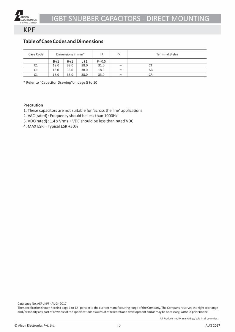
Precaution1. These capacitors are not suitable for ‘across the line’ applications2. VAC (rated) : Frequency should be less than 1000Hz3. VDC(rated) : 1.4 x Vrms + VDC should be less than rated VDC4. MAX ESR = Typical ESR +30%
Table of Case Codes and Dimensions
C1
C1
C1
18.0
31.0
33.0
18.0
18.0
18.0
33.0
33.0
33.0
38.0
38.0
38.0
__
_
Dimensions in mm* P2P1Case Code Terminal Styles
B+- 1 H+- 1 +-L 1B+1 H+1 +L 1 P+ 0.5CT
AB
CR
* Refer to “Capacitor Drawing”on page 5 to 10
IGBT SNUBBER CAPACITORS - DIRECT MOUNTING
All Products not for marketing / sale in all countries.
© Alcon Electronics Pvt. Ltd. AUG 2017