Embed Size (px)
Citation preview
2A
IGNITION
90-859769R1 DECEMBER 2000 Page 2A-1
ELECTRICALSection 2A – Ignition
Table of Contents
Specifications 2A-1. . . . . . . . . . . . . . . . . . . . . . . . . . . Special Tools 2A-2. . . . . . . . . . . . . . . . . . . . . . . . . . . Electrical Components Model Year 2000 2A-4. . . Electrical Components 2A-6. . . . . . . . . . . . . . . . . . . . . Coil Plate 2A-8. . . . . . . . . . . . . . . . . . . . . . . . . . . . . . . . Solenoid Plate 2A-10. . . . . . . . . . . . . . . . . . . . . . . . . . . Theory of Operation 2A-13. . . . . . . . . . . . . . . . . . . . . Ignition Component Description 2A-14. . . . . . . . . . .
Fuses 2A-14. . . . . . . . . . . . . . . . . . . . . . . . . . . . . . . Electronic Control Module (ECM) 2A-15. . . . . . . Flywheel 2A-16. . . . . . . . . . . . . . . . . . . . . . . . . . . . Ignition Coils 2A-16. . . . . . . . . . . . . . . . . . . . . . . . . Coil Driver 2A-17. . . . . . . . . . . . . . . . . . . . . . . . . . . Crank Position Sensor 2A-18. . . . . . . . . . . . . . . . Throttle Position Sensor (TPS) 2A-18. . . . . . . . . Throttle Position Sensor (TPS)Troubleshooting 2A-19. . . . . . . . . . . . . . . . . . . . . . Charging System Alternator 2A-20. . . . . . . . . . . . Temperature Sensor 2A-21. . . . . . . . . . . . . . . . . . Manifold Absolute Pressure(MAP) Sensor 2A-23. . . . . . . . . . . . . . . . . . . . . . . . Air Temperature Sensor 2A-23. . . . . . . . . . . . . . .
Direct Injectors 2A-24. . . . . . . . . . . . . . . . . . . . . . . Fuel Injectors 2A-24. . . . . . . . . . . . . . . . . . . . . . . . Disconnecting Harness Connectors fromIgnition Coils and/or Injectors 2A-25. . . . . . . . . . Shift Interrupt Switch 2A-25. . . . . . . . . . . . . . . . . . Troubleshooting 2A-26. . . . . . . . . . . . . . . . . . . . . .
Troubleshooting Without DigitalDiagnostic Terminal 2A-26. . . . . . . . . . . . . . . . . . . . . . Troubleshooting with the DigitalDiagnostic Terminal 2A-27. . . . . . . . . . . . . . . . . . . . . . Notes: 2A-28. . . . . . . . . . . . . . . . . . . . . . . . . . . . . . . . . DDT Functions – Version 4.0 and 4.1 2A-29. . . . . . DDT Functions – Version 1.0 2A-30. . . . . . . . . . . . . DFI Troubleshooting Guide 2A-31. . . . . . . . . . . . . . . Ignition Components Removal and Installation 2A-35. . . . . . . . . . . . . . . . . . . . . . . . . . . .
Flywheel Cover 2A-35. . . . . . . . . . . . . . . . . . . . . . Electronic Control Module (ECM) 2A-36. . . . . . . . Ignition Module 2A-37. . . . . . . . . . . . . . . . . . . . . . . . Crank Position Sensor 2A-38. . . . . . . . . . . . . . . . . Throttle Position Sensor (TPS) 2A-39. . . . . . . . . .
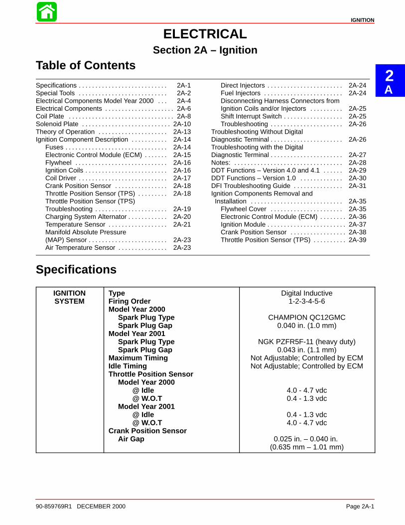
Specifications
IGNITIONSYSTEM
TypeFiring OrderModel Year 2000
Spark Plug TypeSpark Plug Gap
Model Year 2001Spark Plug TypeSpark Plug Gap
Maximum TimingIdle TimingThrottle Position Sensor
Model Year 2000@ Idle@ W.O.T
Model Year 2001@ Idle@ W.O.T
Crank Position SensorAir Gap
Digital Inductive1-2-3-4-5-6
CHAMPION QC12GMC0.040 in. (1.0 mm)
NGK PZFR5F-11 (heavy duty)0.043 in. (1.1 mm)
Not Adjustable; Controlled by ECMNot Adjustable; Controlled by ECM
4.0 - 4.7 vdc0.4 - 1.3 vdc
0.4 - 1.3 vdc4.0 - 4.7 vdc
0.025 in. – 0.040 in. (0.635 mm – 1.01 mm)
IGNITION
Page 2A-2 90-859769R1 DECEMBER 2000
Special Tools
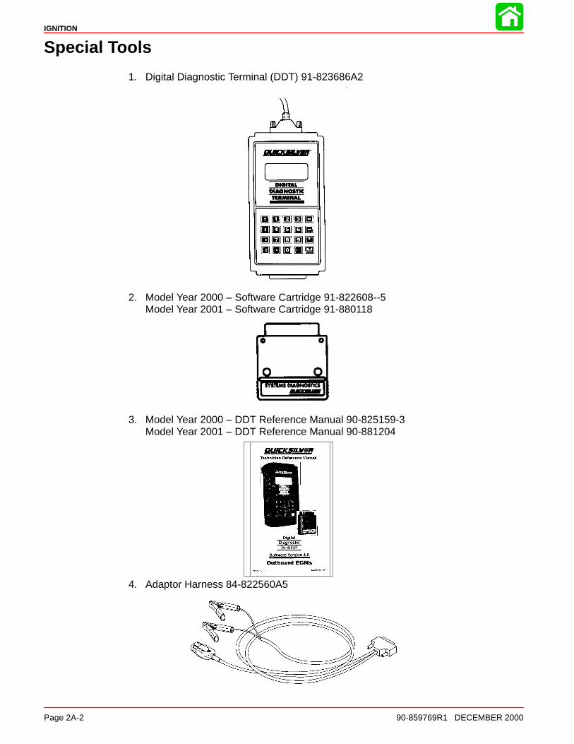
1. Digital Diagnostic Terminal (DDT) 91-823686A2
2. Model Year 2000 – Software Cartridge 91-822608--5Model Year 2001 – Software Cartridge 91-880118
3. Model Year 2000 – DDT Reference Manual 90-825159-3Model Year 2001 – DDT Reference Manual 90-881204
4. Adaptor Harness 84-822560A5
IGNITION
90-859769R1 DECEMBER 2000 Page 2A-3
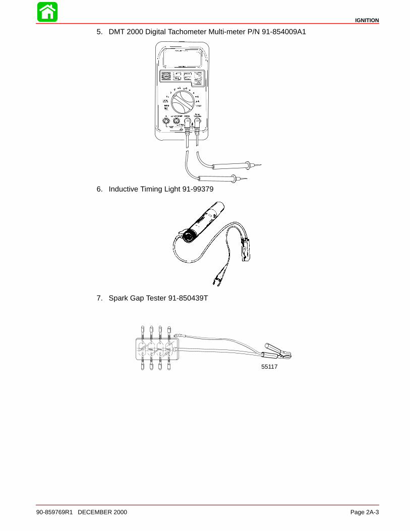
5. DMT 2000 Digital Tachometer Multi-meter P/N 91-854009A1
6. Inductive Timing Light 91-99379
7. Spark Gap Tester 91-850439T
55117
IGNITION
Page 2A-4 90-859769R1 DECEMBER 2000
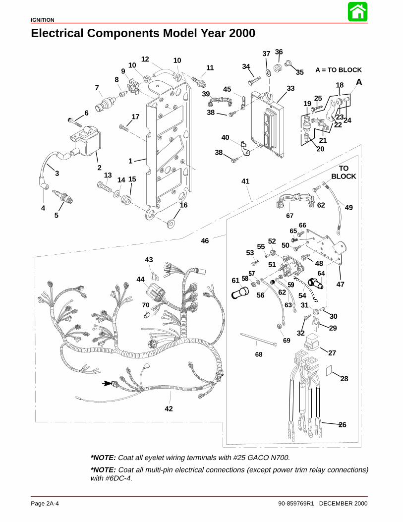
Electrical Components Model Year 2000
12
3
5
6
1314 15
16
17
26
29
30
32
62
42
43
45 33
34
36
38
39
41
48
49
50
51
52
5355
5758
59
35
56
61
27
28
4
7
1012
TOBLOCK
37
44
38
46
47
8
62
A
40
109
18
19
2021
222324
25
11 A = TO BLOCK
63
64
6566
67
68
69
70 3154
*NOTE: Coat all eyelet wiring terminals with #25 GACO N700.
*NOTE: Coat all multi-pin electrical connections (except power trim relay connections)with #6DC-4.
IGNITION
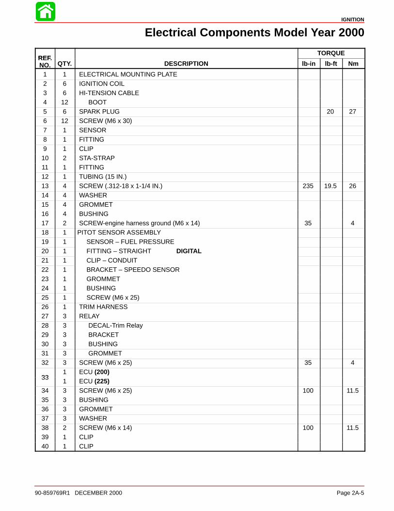
90-859769R1 DECEMBER 2000 Page 2A-5
Electrical Components Model Year 2000
REFTORQUE
REF.NO. QTY. DESCRIPTION lb-in lb-ft Nm
1 1 ELECTRICAL MOUNTING PLATE2 6 IGNITION COIL3 6 HI-TENSION CABLE4 12 BOOT5 6 SPARK PLUG 20 276 12 SCREW (M6 x 30)7 1 SENSOR
8 1 FITTING9 1 CLIP10 2 STA-STRAP11 1 FITTING12 1 TUBING (15 IN.)13 4 SCREW (.312-18 x 1-1/4 IN.) 235 19.5 26
14 4 WASHER15 4 GROMMET16 4 BUSHING17 2 SCREW-engine harness ground (M6 x 14) 35 418 1 PITOT SENSOR ASSEMBLY19 1 SENSOR – FUEL PRESSURE20 1 FITTING – STRAIGHT DIGITAL21 1 CLIP – CONDUIT22 1 BRACKET – SPEEDO SENSOR23 1 GROMMET24 1 BUSHING25 1 SCREW (M6 x 25)26 1 TRIM HARNESS27 3 RELAY
28 3 DECAL-Trim Relay29 3 BRACKET30 3 BUSHING31 3 GROMMET32 3 SCREW (M6 x 25) 35 4
331 ECU (200)
331 ECU (225)
34 3 SCREW (M6 x 25) 100 11.535 3 BUSHING36 3 GROMMET37 3 WASHER38 2 SCREW (M6 x 14) 100 11.539 1 CLIP40 1 CLIP
IGNITION
Page 2A-6 90-859769R1 DECEMBER 2000
Electrical Components
12
3
5
6
1314 15
16
17
26
29
30
32
60
42
43
45 33
34
36
38
39
41
48
49
50
51
52
5352
5758
59
35
56
61
27
28
4
7
1012
TOBLOCK
37
44
38
46
47
8
62
A
40
109
18
19
2021
222324
25
63
64
6566
67
68
11
69
A = TO BLOCK
NOTE: COAT ALL EYELET WIRING TERMINALS WITH #25 GACO N700NOTE: COAT ALL MULTI-PIN ELECTRICAL CONNECTIONS (EXCEPT POWER TRIM RELAY CONNEC-TORS) WITH #6 DC-4
70 3154
A = TO BLOCK
IGNITION
90-859769R1 DECEMBER 2000 Page 2A-7
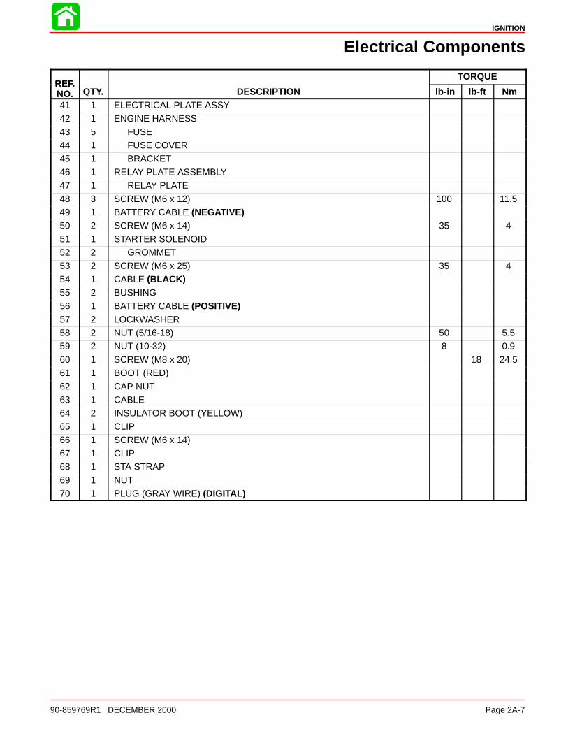
Electrical Components
REFTORQUE
REF.NO. QTY. DESCRIPTION lb-in lb-ft Nm41 1 ELECTRICAL PLATE ASSY
42 1 ENGINE HARNESS43 5 FUSE44 1 FUSE COVER45 1 BRACKET46 1 RELAY PLATE ASSEMBLY47 1 RELAY PLATE
48 3 SCREW (M6 x 12) 100 11.549 1 BATTERY CABLE (NEGATIVE)50 2 SCREW (M6 x 14) 35 451 1 STARTER SOLENOID52 2 GROMMET53 2 SCREW (M6 x 25) 35 454 1 CABLE (BLACK)55 2 BUSHING56 1 BATTERY CABLE (POSITIVE)57 2 LOCKWASHER58 2 NUT (5/16-18) 50 5.559 2 NUT (10-32) 8 0.960 1 SCREW (M8 x 20) 18 24.561 1 BOOT (RED)
62 1 CAP NUT63 1 CABLE64 2 INSULATOR BOOT (YELLOW)65 1 CLIP66 1 SCREW (M6 x 14)67 1 CLIP68 1 STA STRAP
69 1 NUT70 1 PLUG (GRAY WIRE) (DIGITAL)
IGNITION
Page 2A-8 90-859769R1 DECEMBER 2000
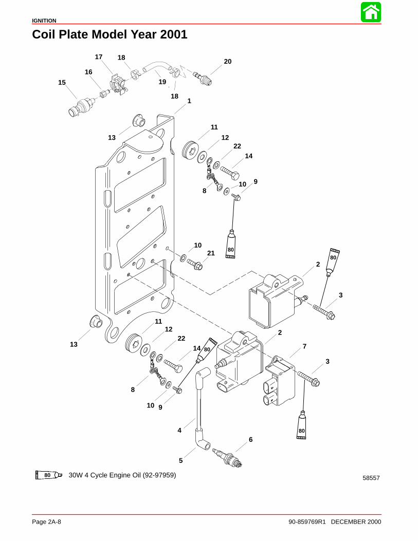
Coil Plate Model Year 2001
58557
1
2
3
3
4
5
6
7
8
8
9
910
10
11
2
11
12
12
13
13
14
14
15
16
17 18
18
19
20
21
30W 4 Cycle Engine Oil (92-97959)80
10
8080
80
80
22
22
IGNITION
90-859769R1 DECEMBER 2000 Page 2A-9
Coil Plate Model Year 2001
REFTORQUE
REF.NO. QTY. DESCRIPTION lb-in lb-ft Nm
1 1 COIL MOUNTING PLATE
2 6 IGNITION COIL3 12 SCREW 60 74 6 HIGH TENSION CABLE5 12 BOOT6 6 SPARK PLUG 20 277 3 DUAL COIL DRIVER
8 2 CABLE9 2 SCREW (M6 x 10) 60 710 4 WASHER11 4 GROMMET12 4 WASHER13 4 BUSHING14 4 SCREW (.312-18 x 1-1/4 IN.) 20 27
15 1 SENSOR16 1 FITTING 40 4.517 1 CLIP18 2 STA STRAP19 1 TUBING (15 IN.)20 1 FITTING21 2 SCREW (M6 x 14)
22 2 WASHER

IGNITION
Page 2A-10 90-859769R1 DECEMBER 2000
Solenoid Plate Model Year 2001
TOBLOCK
A A = TO BLOCK
1
2
345
67
8
9
10
10
11
12
13
14
15
16
17
18
19
20
21
22
23
24
25
26
27
28
2930
31
32
33
34
35
36
37
3839
40
41
42
34
6
4
4 9
43
44
45
46
47
34
24
23
*NOTE: Coat all eyelet wiring terminals with #25 GACO N700.
*NOTE: Coat all multi-pin electrical connections (except power trim relay connections)with #6DC-4.
IGNITION
90-859769R1 DECEMBER 2000 Page 2A-11
Solenoid Plate Model Year 2001
REFTORQUE
REF.NO. QTY. DESCRIPTION lb-in lb-ft Nm
1 1 SOLENOID PLATE2 1 SOLENOID3 2 GROMMET4 5 SCREW (M6 x 25) 35 45 2 BUSHING6 3 RELAY ASSEMBLY7 3 DECAL
8 3 BRACKET9 3 BUSHING10 3 GROMMET11 1 ENGINE HARNESS12 5 FUSE (4 – 20 AMP) (1 – 15 AMP)13 1 FUSE COVER
14 1 HARNESS (DIRECT INJECTOR)15 1 HARNESS (FUEL INJECTOR)16 1 HARNESS (TPS)17 3 SCREW-(M6 x 12) 100 11.518 1 TRIM HARNESS19 1 INSULATOR BOOT (RED)20 1 INSULATOR BOOT (YELLOW)
21 1 CABLE (RED)22 1 CAP NUT23 2 NUT (5/16-18) 50 5.524 2 NUT (10-32) (BRASS) 8 0.925 2 LOCKWASHER26 1 CLIP27 1 CLIP
281 ECU (200)
281 ECU (225)
29 3 SCREW (M6 x 25) 100 11.530 3 BUSHING31 3 GROMMET32 3 WASHER33 1 CLIP
34 5 SCREW (M6 x 14) 100 11.535 1 SENSOR – SPEEDOMETER WATER PRESSURE36 1 FITTING 50 5.537 1 CLIP38 1 BRACKET39 1 GROMMET40 1 BUSHING
41 1 SCREW (M6 x 25) 35 442 1 CLIP43 2 STA–STRAP
IGNITION
Page 2A-12 90-859769R1 DECEMBER 2000
Solenoid Plate Model Year 2001
TOBLOCK
A A = TO BLOCK
1
2
345
67
8
9
10
10
11
12
13
14
15
16
17
18
19
20
21
22
23
24
25
26
27
28
2930
31
32
33
34
35
36
37
3839
40
41
42
34
6
4
4 9
43
44
45
46
47
34
24
23
*NOTE: Coat all eyelet wiring terminals with #25 GACO N700.
*NOTE: Coat all multi-pin electrical connections (except power trim relay connections)with #6DC-4.
IGNITION
90-859769R1 DECEMBER 2000 Page 2A-13
Solenoid Plate Model Year 2001
REFTORQUE
REF.NO. QTY. DESCRIPTION lb-in lb-ft Nm44 1 CABLE
45 1 SCREW (M8 x 20) 18 24.546 1 BATTERY CABLE (NEGATIVE)47 1 BRACKET
Theory of Operation
When the ignition key is turned to the RUN position, battery voltage is applied to the mainrelay through the PURPLE wire. When the Electronic Control Module (ECM) receives asignal from the Crank Position Sensor, the main relay ground circuit is completed throughthe ECM. The main relay is then closed and D.C. current from the battery or charging sys-tem is transferred through the main relay 20 ampere fuse to the positive terminal of all 6ignition coil primary windings. The negative terminal of the coil primary is connected toengine ground through the ECM. When this circuit is closed, a magnetic field is allowedto be built up in the ignition coil. The Crank Position Sensor senses the location of the 24teeth (Model 2000) or 54 teeth (Model 2001) on the flywheel and supplies a trigger signalto the ECM. When the ECM receives this signal, the ECM will then open the ground circuitof the coil primary. The magnetic field in the ignition coil primary will then collapse cuttingacross the coil secondary winding creating a high voltage charge (50,000 volts) that issent to the spark plug.
IGNITION
Page 2A-14 90-859769R1 DECEMBER 2000
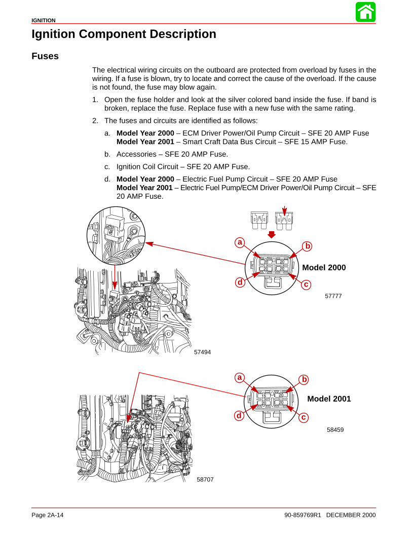
Ignition Component Description
FusesThe electrical wiring circuits on the outboard are protected from overload by fuses in thewiring. If a fuse is blown, try to locate and correct the cause of the overload. If the causeis not found, the fuse may blow again.
1. Open the fuse holder and look at the silver colored band inside the fuse. If band isbroken, replace the fuse. Replace fuse with a new fuse with the same rating.
2. The fuses and circuits are identified as follows:
a. Model Year 2000 – ECM Driver Power/Oil Pump Circuit – SFE 20 AMP FuseModel Year 2001 – Smart Craft Data Bus Circuit – SFE 15 AMP Fuse.
b. Accessories – SFE 20 AMP Fuse.
c. Ignition Coil Circuit – SFE 20 AMP Fuse.
d. Model Year 2000 – Electric Fuel Pump Circuit – SFE 20 AMP FuseModel Year 2001 – Electric Fuel Pump/ECM Driver Power/Oil Pump Circuit – SFE20 AMP Fuse.
57494
57777
a b
cd
Model 2000
Model 2001
a
58459
d c
b
58707
IGNITION
90-859769R1 DECEMBER 2000 Page 2A-15
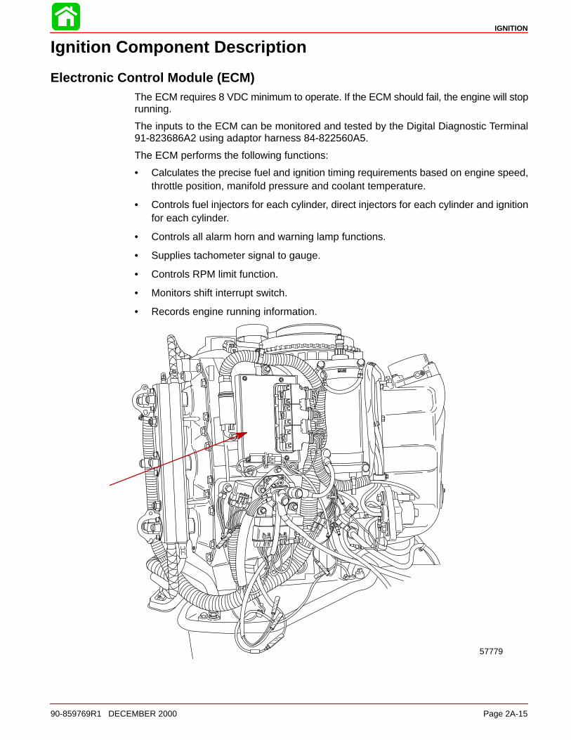
Ignition Component Description
Electronic Control Module (ECM)The ECM requires 8 VDC minimum to operate. If the ECM should fail, the engine will stoprunning.
The inputs to the ECM can be monitored and tested by the Digital Diagnostic Terminal91-823686A2 using adaptor harness 84-822560A5.
The ECM performs the following functions:
• Calculates the precise fuel and ignition timing requirements based on engine speed,throttle position, manifold pressure and coolant temperature.
• Controls fuel injectors for each cylinder, direct injectors for each cylinder and ignitionfor each cylinder.
• Controls all alarm horn and warning lamp functions.
• Supplies tachometer signal to gauge.
• Controls RPM limit function.
• Monitors shift interrupt switch.
• Records engine running information.
57779
IGNITION
Page 2A-16 90-859769R1 DECEMBER 2000
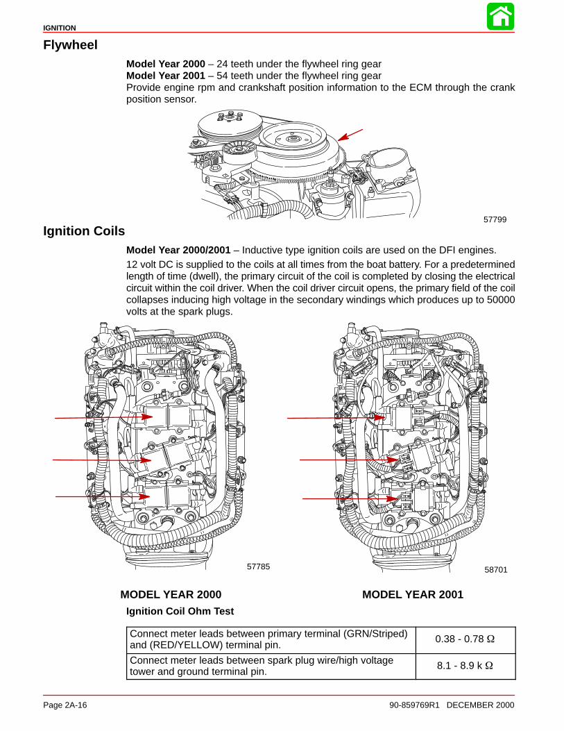
FlywheelModel Year 2000 – 24 teeth under the flywheel ring gearModel Year 2001 – 54 teeth under the flywheel ring gear Provide engine rpm and crankshaft position information to the ECM through the crankposition sensor.
57799
Ignition CoilsModel Year 2000/2001 – Inductive type ignition coils are used on the DFI engines.12 volt DC is supplied to the coils at all times from the boat battery. For a predeterminedlength of time (dwell), the primary circuit of the coil is completed by closing the electricalcircuit within the coil driver. When the coil driver circuit opens, the primary field of the coilcollapses inducing high voltage in the secondary windings which produces up to 50000volts at the spark plugs.
57785
MODEL YEAR 2000 MODEL YEAR 2001
58701
Ignition Coil Ohm Test
Connect meter leads between primary terminal (GRN/Striped)and (RED/YELLOW) terminal pin.
0.38 - 0.78 �
Connect meter leads between spark plug wire/high voltagetower and ground terminal pin.
8.1 - 8.9 k �
IGNITION
90-859769R1 DECEMBER 2000 Page 2A-17
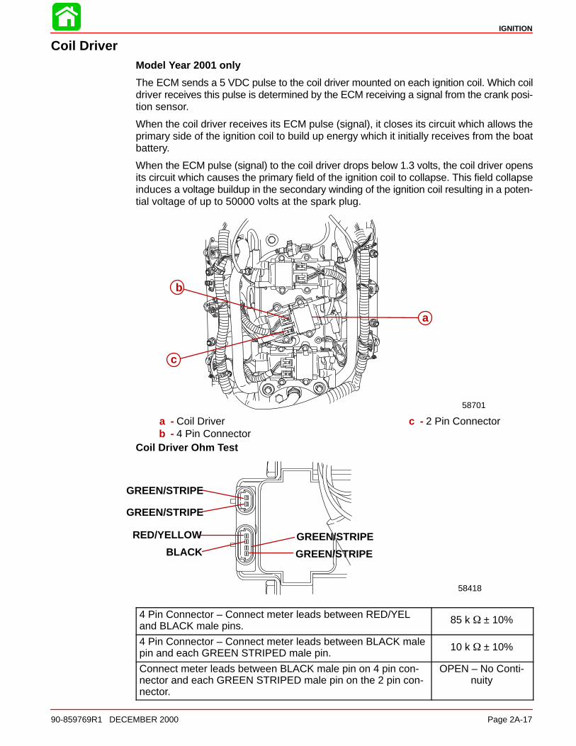
Coil DriverModel Year 2001 only
The ECM sends a 5 VDC pulse to the coil driver mounted on each ignition coil. Which coildriver receives this pulse is determined by the ECM receiving a signal from the crank posi-tion sensor.
When the coil driver receives its ECM pulse (signal), it closes its circuit which allows theprimary side of the ignition coil to build up energy which it initially receives from the boatbattery.
When the ECM pulse (signal) to the coil driver drops below 1.3 volts, the coil driver opensits circuit which causes the primary field of the ignition coil to collapse. This field collapseinduces a voltage buildup in the secondary winding of the ignition coil resulting in a poten-tial voltage of up to 50000 volts at the spark plug.
a
b
c
58701
a - Coil Driverb - 4 Pin Connector
c - 2 Pin Connector
Coil Driver Ohm Test
58418
GREEN/STRIPE
GREEN/STRIPE
GREEN/STRIPE
GREEN/STRIPE
RED/YELLOW
BLACK
4 Pin Connector – Connect meter leads between RED/YELand BLACK male pins.
85 k � ± 10%
4 Pin Connector – Connect meter leads between BLACK malepin and each GREEN STRIPED male pin.
10 k � ± 10%
Connect meter leads between BLACK male pin on 4 pin con-nector and each GREEN STRIPED male pin on the 2 pin con-nector.
OPEN – No Conti-nuity
IGNITION
Page 2A-18 90-859769R1 DECEMBER 2000
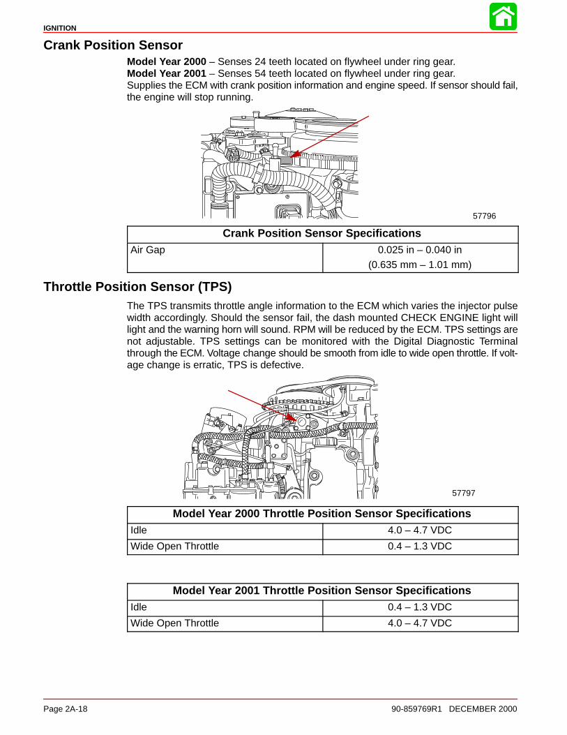
Crank Position SensorModel Year 2000 – Senses 24 teeth located on flywheel under ring gear.Model Year 2001 – Senses 54 teeth located on flywheel under ring gear.Supplies the ECM with crank position information and engine speed. If sensor should fail,the engine will stop running.
57796
Crank Position Sensor SpecificationsAir Gap 0.025 in – 0.040 in
(0.635 mm – 1.01 mm)
Throttle Position Sensor (TPS)The TPS transmits throttle angle information to the ECM which varies the injector pulsewidth accordingly. Should the sensor fail, the dash mounted CHECK ENGINE light willlight and the warning horn will sound. RPM will be reduced by the ECM. TPS settings arenot adjustable. TPS settings can be monitored with the Digital Diagnostic Terminalthrough the ECM. Voltage change should be smooth from idle to wide open throttle. If volt-age change is erratic, TPS is defective.
57797
Model Year 2000 Throttle Position Sensor SpecificationsIdle 4.0 – 4.7 VDC
Wide Open Throttle 0.4 – 1.3 VDC
Model Year 2001 Throttle Position Sensor SpecificationsIdle 0.4 – 1.3 VDC
Wide Open Throttle 4.0 – 4.7 VDC
IGNITION
90-859769R1 DECEMBER 2000 Page 2A-19
Throttle Position Sensor (TPS) TroubleshootingIf the throttle position sensor(s) are out of the intended operating range when the engineis started, the Electronic Control Module (ECM) will sense that the Throttle Position Sen-sor (TPS) has failed. The warning horn will sound, check engine light will illuminate DDTwill indicate failed TPS and the engine will go into RPM reduction. When the engine isstarted, the throttle arm on the engine must be against the throttle stop screw.
• Check throttle cable adjustment. The throttle stop screw on the throttle arm must beagainst the throttle stop on the cylinder block when the engine is started. Pre-load thethrottle cable barrel 1 or 2 turns if necessary.
• Verify driver is not pushing on throttle (if foot throttle is used) or advancing the throttleonly on the control box.
• Check throttle cam to roller adjustment. If the roller is not down in the pocket/valleyarea on the cam, there is a tendency for the roller to ride up or down on the cam whichcauses the TPS link arm to push/pull on the TPS lever resulting changing values.
• Heat or pressure test the TPS.
HEAT TEST
With engine at idle, heat the TPS (with a hot air gun) below the electrical connection untilwarm to the touch. Watch for any one or a combination of the following symptoms:
• RPM change
• Check engine light illumination
• Momentary warning horn signal
• TPS voltage value change (1/2 volt) on DDT
*NOTE: Excessive heat will damage TPS.
PRESSURE TEST
IMPORTANT: When testing TPS voltage, do not move the drive mechanism (rotor/wiper).
1. Connect DDT and rotate the key to the “ON” position.
2. Set DDT to read TPS voltage; expand the screen to show Now/Min/Max.
*NOTE: Test accuracy is improved when TPS is at its lowest voltage reading; this maybe idle or WOT depending on model year.
3. Clear the minimum/maximum values on the DDT – press the “0” button.
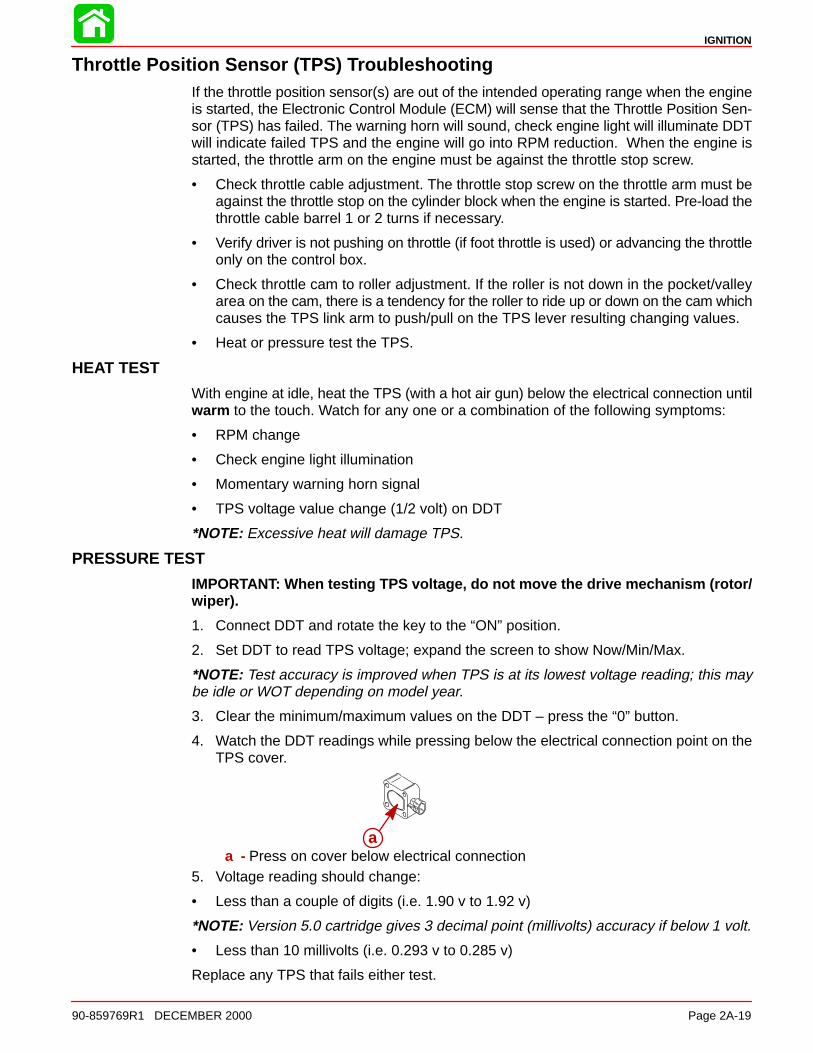
4. Watch the DDT readings while pressing below the electrical connection point on theTPS cover.
aa - Press on cover below electrical connection
5. Voltage reading should change:
• Less than a couple of digits (i.e. 1.90 v to 1.92 v)
*NOTE: Version 5.0 cartridge gives 3 decimal point (millivolts) accuracy if below 1 volt.
• Less than 10 millivolts (i.e. 0.293 v to 0.285 v)
Replace any TPS that fails either test.
IGNITION
Page 2A-20 90-859769R1 DECEMBER 2000
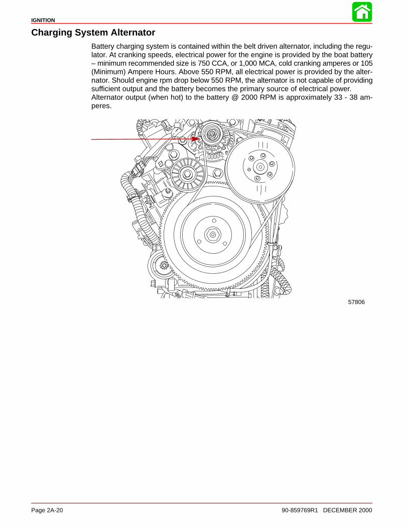
Charging System AlternatorBattery charging system is contained within the belt driven alternator, including the regu-lator. At cranking speeds, electrical power for the engine is provided by the boat battery– minimum recommended size is 750 CCA, or 1,000 MCA, cold cranking amperes or 105(Minimum) Ampere Hours. Above 550 RPM, all electrical power is provided by the alter-nator. Should engine rpm drop below 550 RPM, the alternator is not capable of providingsufficient output and the battery becomes the primary source of electrical power. Alternator output (when hot) to the battery @ 2000 RPM is approximately 33 - 38 am-peres.
57806
IGNITION
90-859769R1 DECEMBER 2000 Page 2A-21
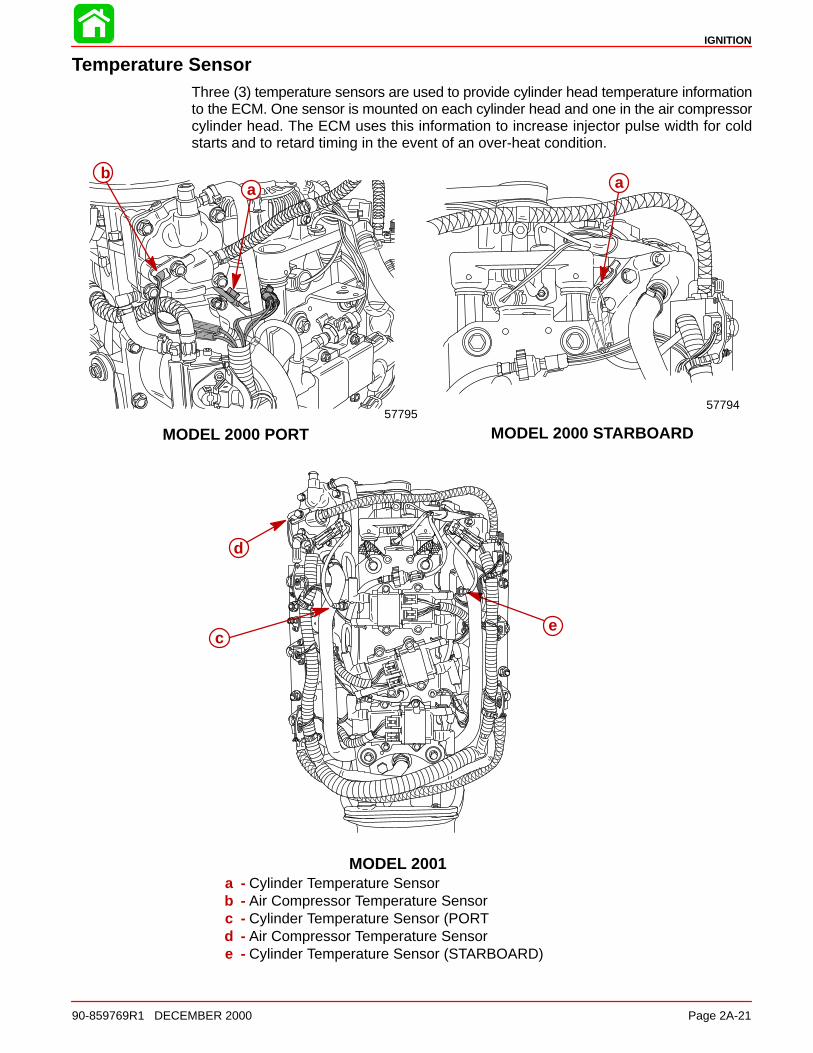
Temperature SensorThree (3) temperature sensors are used to provide cylinder head temperature informationto the ECM. One sensor is mounted on each cylinder head and one in the air compressorcylinder head. The ECM uses this information to increase injector pulse width for coldstarts and to retard timing in the event of an over-heat condition.
57794
a
57795
b
MODEL 2001
MODEL 2000 STARBOARDMODEL 2000 PORT
a
d
ce
a - Cylinder Temperature Sensorb - Air Compressor Temperature Sensorc - Cylinder Temperature Sensor (PORTd - Air Compressor Temperature Sensore - Cylinder Temperature Sensor (STARBOARD)
IGNITION
Page 2A-22 90-859769R1 DECEMBER 2000
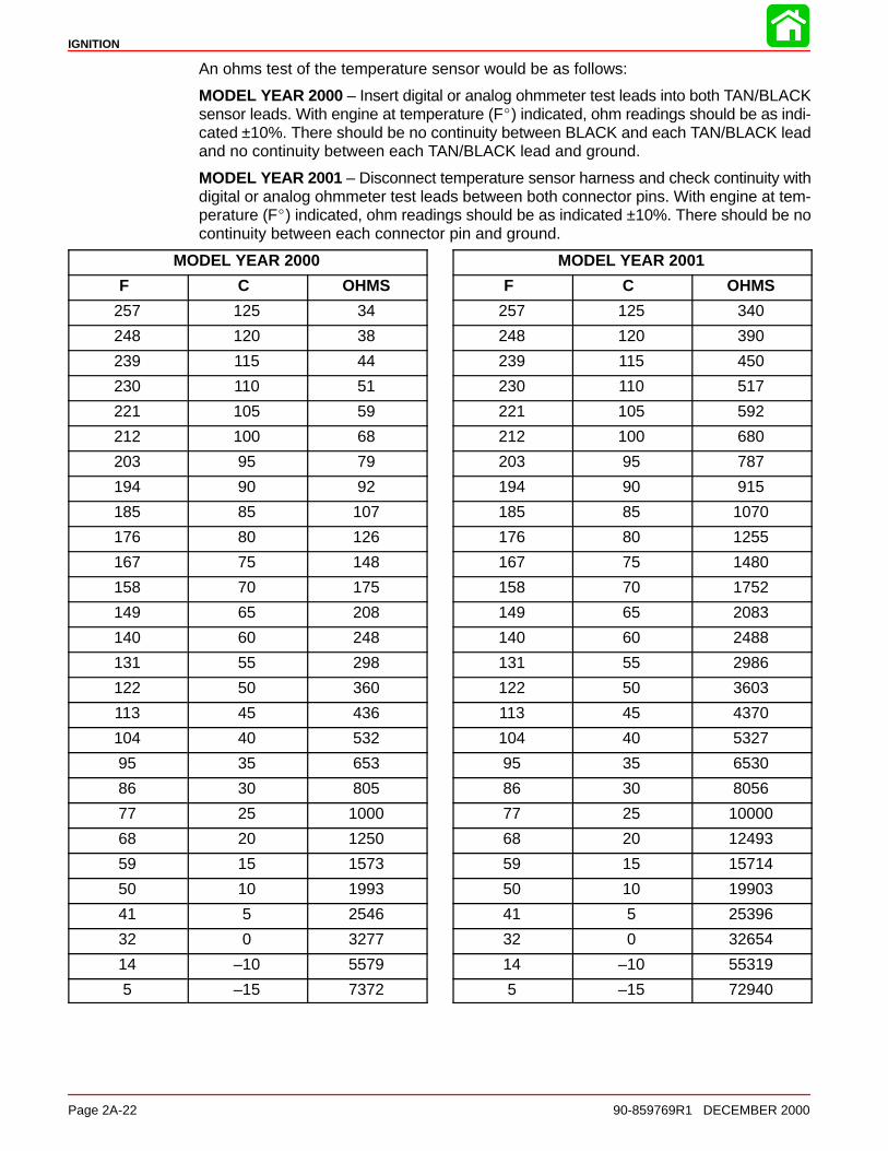
An ohms test of the temperature sensor would be as follows:
MODEL YEAR 2000 – Insert digital or analog ohmmeter test leads into both TAN/BLACKsensor leads. With engine at temperature (F�) indicated, ohm readings should be as indi-cated ±10%. There should be no continuity between BLACK and each TAN/BLACK leadand no continuity between each TAN/BLACK lead and ground.
MODEL YEAR 2001 – Disconnect temperature sensor harness and check continuity withdigital or analog ohmmeter test leads between both connector pins. With engine at tem-perature (F�) indicated, ohm readings should be as indicated ±10%. There should be nocontinuity between each connector pin and ground.
MODEL YEAR 2000
F C OHMS
257 125 34
248 120 38
239 115 44
230 110 51
221 105 59
212 100 68
203 95 79
194 90 92
185 85 107
176 80 126
167 75 148
158 70 175
149 65 208
140 60 248
131 55 298
122 50 360
113 45 436
104 40 532
95 35 653
86 30 805
77 25 1000
68 20 1250
59 15 1573
50 10 1993
41 5 2546
32 0 3277
14 –10 5579
5 –15 7372
MODEL YEAR 2001
F C OHMS
257 125 340
248 120 390
239 115 450
230 110 517
221 105 592
212 100 680
203 95 787
194 90 915
185 85 1070
176 80 1255
167 75 1480
158 70 1752
149 65 2083
140 60 2488
131 55 2986
122 50 3603
113 45 4370
104 40 5327
95 35 6530
86 30 8056
77 25 10000
68 20 12493
59 15 15714
50 10 19903
41 5 25396
32 0 32654
14 –10 55319
5 –15 72940
IGNITION
90-859769R1 DECEMBER 2000 Page 2A-23
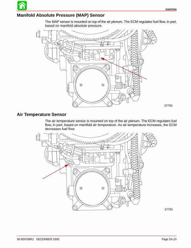
Manifold Absolute Pressure (MAP) SensorThe MAP sensor is mounted on top of the air plenum. The ECM regulates fuel flow, in part,based on manifold absolute pressure.
57793
Air Temperature SensorThe air temperature sensor is mounted on top of the air plenum. The ECM regulates fuelflow, in part, based on manifold air temperature. As air temperature increases, the ECMdecreases fuel flow.
57793
IGNITION
Page 2A-24 90-859769R1 DECEMBER 2000
Direct Injectors6 direct injectors (1 per cylinder) are used to inject a fuel/air mix into cylinders. Injectorsare mounted between fuel rails and cylinder heads.
57986 57985
Direct Injector Ohm Test (Injector Lead Disconnected)
Connect meter leads between each in-jector terminal pin.
1 - 1.6 �
Connect 1 meter lead to either injectorpin while touching the other meter lead tothe injector metal case.
No continuity
Fuel Injectors6 fuel injectors (1 per cylinder) are used to provide fuel from the fuel rail to the direct injec-tors. The fuel injectors are mounted in the fuel rail.
57785
Fuel Injector Ohm Test (Injector Lead Disconnected)
Connect meter leads between each in-jector terminal pin.
1.7 - 1.9 �
IGNITION
90-859769R1 DECEMBER 2000 Page 2A-25
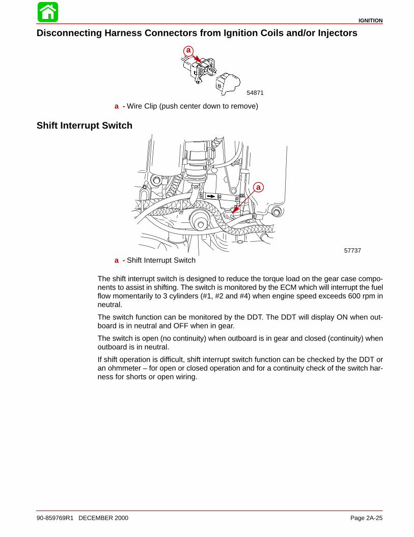
Disconnecting Harness Connectors from Ignition Coils and/or Injectors
54871
a
a - Wire Clip (push center down to remove)
Shift Interrupt Switch
57737
a
a - Shift Interrupt Switch
The shift interrupt switch is designed to reduce the torque load on the gear case compo-nents to assist in shifting. The switch is monitored by the ECM which will interrupt the fuelflow momentarily to 3 cylinders (#1, #2 and #4) when engine speed exceeds 600 rpm inneutral.
The switch function can be monitored by the DDT. The DDT will display ON when out-board is in neutral and OFF when in gear.
The switch is open (no continuity) when outboard is in gear and closed (continuity) whenoutboard is in neutral.
If shift operation is difficult, shift interrupt switch function can be checked by the DDT oran ohmmeter – for open or closed operation and for a continuity check of the switch har-ness for shorts or open wiring.
IGNITION
Page 2A-26 90-859769R1 DECEMBER 2000
TroubleshootingThe ECM is designed such that if a sensor fails, the ECM will compensate so that the en-gine does not go into an over-rich condition.
Disconnecting a sensor for troubleshooting purposes may have no noticeable effect.
Troubleshooting Without Digital Diagnostic Terminal
Troubleshooting without the DDT is limited to checking resistance on some of the sen-sors.
Typical failures usually do not involve the ECM. Connectors, set-up, and mechanical wearare most likely at fault.
• Verify spark plug wires are securely installed (pushed on) on the coil tower.
• The engine may not run or may not run above idle with the wrong spark plugs installed.
• Swap ignition coils to see if the problem follows the coil or stays with the particularcylinder.
*NOTE: ECMs are capable of performing a cylinder misfire test to isolate problem cylin-ders. Once a suspect cylinder is located, an output load test on the ignition coil, fuel injec-tor and direct injector may be initiated through use of the DDT.
• Any sensor or connection can be disconnected and reconnected while the engine isoperating without damaging the ECM. Disconnecting the crank position sensor willstop the engine.
IMPORTANT: Any sensor that is disconnected while the engine is running will berecorded as a Fault in the ECM Fault History. Use the DDT to view and clear the faulthistory when troubleshooting/repair is completed.
• If all cylinders exhibit similar symptoms, the problem is with a sensor or harness inputto the ECM.
• If problem is speed related or intermittent, it is probably connector or contact related.Inspect connectors for corrosion, loose wires or loose pins. Secure connector seating;use dielectric compound 92-823506-1.
• Inspect the harness for obvious damage: pinched wires, chaffing.
• Secure grounds and all connections involving ring terminals (coat with Liquid Neo-prene 92-25711--3).
• Check fuel pump connections and fuel pump pressure.
• Check air compressor pressure.
IGNITION
90-859769R1 DECEMBER 2000 Page 2A-27
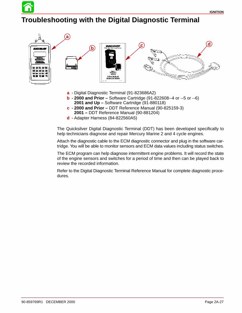
Troubleshooting with the Digital Diagnostic Terminal
a
bc d
a - Digital Diagnostic Terminal (91-823686A2)b - 2000 and Prior – Software Cartridge (91-822608--4 or --5 or --6)
2001 and Up – Software Cartridge (91-880118)c - 2000 and Prior – DDT Reference Manual (90-825159-3)
2001 – DDT Reference Manual (90-881204)d - Adapter Harness (84-822560A5)
The Quicksilver Digital Diagnostic Terminal (DDT) has been developed specifically tohelp technicians diagnose and repair Mercury Marine 2 and 4 cycle engines.
Attach the diagnostic cable to the ECM diagnostic connector and plug in the software car-tridge. You will be able to monitor sensors and ECM data values including status switches.
The ECM program can help diagnose intermittent engine problems. It will record the stateof the engine sensors and switches for a period of time and then can be played back toreview the recorded information.
Refer to the Digital Diagnostic Terminal Reference Manual for complete diagnostic proce-dures.

IGNITION
Page 2A-28 90-859769R1 DECEMBER 2000
Notes:
IGNITION
Page 2A-2990-859769R1 DECEMBER 2000
DDT Functions – Optimax Models Software Version 4.0 and 4.1
Select Status:1 - IGNITION2 - INJECTOR3 - PUMP4 - SENSORS5 - SWITCHES6 - MISCELLANEOUS7 - RPM LIMIT8 - BREAK-IN
MARINE DIAGNOSTICS1 - Mariner/Mercury2 - MerCruiser3 - Injector Test4 - Tool Setup
SELECT ECM1 - 3.0L Ignition ECM2 - 3.0L Fuel ECM3 - 824003 Fuel ECM4 - 2.5L Hi Perf ECM5 - DFI ECM6 - 4 Stroke ECM
Select Function:1 - AUTO SELF TEST
2 - MANUAL TEST
Select Function:1 - DATA MONITOR2 - STATUS SWITCHES3 - SYSTEM INFO4 - HISTORY5 - SPECIAL FUNCTIONS
Select Auto Test:1 - STATIC TEST
2 - RUNNING TEST
ENGINE RPMTPI 1 VOLTSTPI 2 VOLTSBATTERY VOLTSPWR 1 VOLTSPWR 2 VOLTSCOOL TMP STB °FCOOL TMP PRT °FMAP PSIAIR TMP °TRIGGER ERRTIME TO OILOIL INJ CNTTPI %AIR COM TMP °FBLOCK PSI
Select Function:1 - FAULT HISTORY2 - RUN HISTORY3 - CLEAR FAULT HIST4 - CLEAR RUN HIST
Select Function:1 - OIL PUMP PRIME2 - CYLINDER MISFIRE3 - OUTPUT LOAD TEST4 - RESET BREAK-IN OIL
98 DI ECM # CODEIGN PRI .38-.78 ohmSEC 8.1-8.9 KohmDINJ 1.0-1.6 ohmFINJ 1.7-1.9 ohmTPI1 3.7-4.9v IDLE
0.3-1.8v WOTTPI2 0.1-1.5v IDLE
3.2-4.9v WOTTPI1 LtBlu/Red INTPI2 LtBlu/Wht OUTTGAP 0.025-.04inPWR RLY 81-99 ohmCTS max 220FACT max 150-220F30-8000 ohm 1K@77FAIR TMP .540-44BATV 12.6-15.0MAP 7-15 psiFUEL 88-90 psiAIR 77-81 psi
Text Book Data(specs)
Monitors Engine FunctionsWhile Engine is Running
SWITCH ACTIVE HISTSHIFT SW ON NAH2O FUEL NO NOL OIL NO NO
PUMP ACTIVE HISTOIL PMP PASS PASS
LIMIT ACTIVE HISTCTS LIM OFF ONCTP LIM OFF OFFACT LIM OFF OFFTP1 LIM OFF OFFTP2 LIM OFF OFFRPM LIM OFF OFFOIL LIM OFF ONBAT LIM OFF OFFBLK LIM OFF OFFPWR LIM OFF OFF
STATUS BREAK-IN ENGINE IS INBREAK-IN MODE. xxx MINUTESTO COMPLETION.
STATUS BREAK-IN ENGINE HASCOMPLETED A FACTORY SCHED-ULED BREAK-IN.
or
MISC. ACTIVE HISTBATTERY PASS PASSPWR RLY PASS PASSPWR 1 V PASS PASSPWR 2 V PASS PASSHORN PASS PASSLAMP PASS PASS
SENSOR ACTIVE HISTCOOL STB PASS PASSCOOL PRT PASS PASSMAP PASS PASSAIR TMP PASS PASSTPI 1 PASS PASSTPI 2 PASS PASSTRIG SIG PASS PASSCOMP TMP PASS PASSBLOCK PSI PASS PASS
INJECTOR ACTIVE HISTINJ 1 PASS PASSINJ 2 PASS PASSINJ 3 PASS PASSINJ 4 PASS PASSINJ 5 PASS PASSINJ 6 PASS PASS
IGN ACTIVE HISTIGN 1 PASS PASSIGN 2 PASS PASSIGN 3 PASS PASSIGN 4 PASS PASSIGN 5 PASS PASSIGN 6 PASS PASS
Engine Not Running During Test
Engine Running During Test
Select Fault Hist:1-IGNITION2-INJECTOR3-PUMP4-SENSORS5-SWITCHES6-MISCELLANEOUSRPM 3000-3999 xx
RPM 4000-4999 xxRPM 5000-5999 xxRPM 6000+ xxBREAK IN Min xxOVER TMP Sec xRPM LIMIT CNT xRPM LIMIT SEC xACT TEMP SEC xBLOCK PSI Sec xCTS TMP Sec xCTP TMP Sec xOIL PMP Sec x
ECM RUN TIME xxRPM 0000-0999 xxRPM 1000-1499 xxRPM 1500-2999 xx
1
2
3
4
5
6
7
8
Any fault in Select Status functions 1 thru 7 will turn on the matching panel light.Illuminated panel light 8 Indicates engine is in Break-in.
NOTE:Test data is lost when Key Switch is turned off. Any existing faults from Tests 1 thru 6 are transferred to Fault History.
1 or 2
1
5
Select Load Test:1 - IGNITION2 - FUEL INJECTOR3 - DIRECT INJECTOR4 - OIL PUMP5 - FUEL PUMP6 - HORN7 - LAMPS8 - TACHOMETER9 - MAIN POWER RELAY
IGNITION
Page 2A-30 90-859769R1 DECEMBER 2000
DDT Functions – Optimax Models Software Version 1.0
IGNITION
INJECTOR
PUMP
SENSORS
SWITCHES
MISCELLANEOUS
RPM LIMIT
BREAK–IN
SmartCraft Monitor
1 – Mercury Marine2 – Tool Setup
Select Auto Test:
1 – STATIC TEST
Select Fault Hist:
1 – FREEZE FRAME2 – FAULT SECONDS
1
2
3
4
5
6
7
8
FAULT LIGHTSFAULT LIGHTS
Any fault will turn on fault light. Refer to
Fault Status to identify fault
ACT INPUT HI or LO
AT INPUT HI or LO
BATT VOLT HI or LOW
BLOCK PRESS LOW
BPSI INPUT HI or LO
BREAK-IN
COMP OVERHEAT
CTP INPUT HI or LO
CTS INPUT HI or LO
DINJ 1 thru 6 SHORT or OPEN
EST 1 thru 6 SHORT or OPEN
FINJ 1 thru 6 SHORT or OPEN
FUEL LVL IN HI or LOGUARDIAN
H2O IN FUEL
MAP INPUT HI or LO
MPRLY OUTPUT
OIL LVL IN HI or LO
OIL PUMPOIL RESERVE STROVERSPEED
PITOT INPUT HI or LOPORT OVERHEAT
SEA TMP IN HI or LO
STAR OVERHEAT
TPI1 RANGE HI or LO
TRIM INPUT HI or LO
WARNING HORN
Air compessor temperature sensor input is high or low
Air temperatrure (engine) sensor input is high or low
Battery voltage is high or low
Block pressure is low
Block Pressure Sensor input is high or low
Compressor overheat
Coolant temp port sensor input is high or lowCoolant temp starboard sensor input is high or low
Direct injector (1 thru 6) is short or open circuit
Electronic spark trigger signal (1 thru 6) is short or open circuit
Fuel injector (1 thru 6) is short or open circuit
Fuel level sensor input is high or lowGuardian system activated
Water in fuel
MAP sensor input high or low
Oil level sensor input is high or low
Oil pump electrical failureOil reserve strategy is activeOverspeed is activated
Pilot Pressure Sensor input is high or lowPort cylinder head overheatSea or lake temperature sensor input is high or low
Starboard cylinder head overheat
TPI #1 is above or below the allowable rangeTrim sensor input is high or low
Warning horn fault
MPRLY BACKFEED
TPI1 INPUT HI or LO TPI #1 sensor input is high or low
TPI1 NO ADAPT ECM is unable to adapt to the current position of the TPI
01MY DI ECM # CODEIGN PRI .38-.78 ohmSEC 8.1-8.9 KohmDINJ 1.0-1.6 ohmFINJ 1.7-1.9 ohmTYPICAL TPI RANGE
TGAP 0.025-.04in
1 FUSE-INJ/OIL PUMP
AIR COMPRESSOR1Kohm @ 77F/25CAIRTEMP/COOLANT10 Kohm @ 77F/25C
RPM LIMIT 5850PROP RPM 5000-5750
2 FUSE-FUEL PUMP
3 FUSE-ACCESSORY
4 FUSE-IGNITION
OIL PUMP COIL1.8-2.0 ohms
OVERTEMP/BLOCK
PRESSURE LIMITS ARE
CONTROLLED BY
ENGINE GUARDIAN
SEE SERVICE MANUAL
FOR GUARDIAN INFO
ENGINE RPMTPI 1 VOLTSBATTERY VOLTSPWR 1 VOLTSCOOL TMP STB °FCOOL TMP PRT °FMAP PSIAIR TMP °FBLOCK PSIOIL INJ CNTTPI %AIR COM TMP °FOIl LEVELFUEL LEVELAVAILABLE PWR %SHIFTTRIMPITOTPADDLE WHEELLAKE/SEA TMP °F
RUN TIME HR.RPM 0 – 749RPM 750 – 1499RPM 1500 – 2999RPM 3000 – 3999RPM 4000 – 4499RPM 4500 – 4999RPM 5000– 5499RPM 5500 – 6249RPM 6250 +BREAK-IN LEFTRPM LIMIT SecGRD LIMIT SecACT TEMP SecBLOCK PSI SecCTS TMP SecCTP TEMP SecLOW OIL SecOIL PMP Sec
Engine Break-In In Progess
Main Power Relay is Receiving a Current Back feedMain Power Relay Output
Fault Status List
Select Load Test:1 - IGNITION2 - FUEL INJECTOR3 - DIRECT INJECTOR4 - OIL PUMP5 - FUEL PUMP6 - HORN7 - Reserve8 - TACHOMETER9 - MAIN POWER RELAY
Select Function:1 - OIL PUMP PRIME2 - CYLINDER MISFIRE3 - OUTPUT LOAD TEST4 - RESET BREAK-IN OIL5 - CHANGE FUEL OFFSET6 - ENGINE LOCATION
THIS ENGINE IS Axx MY xxx x.xL xxxPRESS 1 to CONTINUE
Select Function:1 - DATA MONITOR2 - FAULT STATUS3 - SYSTEM INFO4 - HISTORY5 - SPECIAL FUNCTIONS
Select Function:1 - FAULT HISTORY2 - RUN HISTORY3 - CLEAR FAULT HIST4 - CLEAR RUN HIST
FREEZE FRAME BUFFERS0-BREAK-INBARO PSIBATT VOLTSBLOCK PSIBOAT SPEEDAIR TMP °FCOOL TMP °FDEMAND %ENGINE RPMENGINE STATEFPC TOTALFREQ COUNTERFUEL LEVEL %SHIFTLAKE/SEA TMP °FLOAD%MPRLY REQMAP PSIOIL LEVEL %PORT TAB POSAVAILABLE PWR %RUN TIMESTAR TAB POSTPI %TRIM POSITIONCOOL TMP STB °FCOOL TMP PRT °F
FAULT SECONDSBATT VOLT HIGHBATT VOLT LOWBLOCK PRESS LOWCOMP OVERHEATETC MOTOR OPENETC MOTOR SHORTFUEL P INPUT HIFUEL P INPUT LOGUARDIANKNOCK SENS1KNOCK SENS2OIL PSI STROIL REMOTE STROIL RESERVE STRMAP INPUT HIMAP INPUT LOMAP IDLE CHECKOIL PUMPOVERSPEEDPORT OVERHEATSTAR OVERHEATWARNING HORNH2O IN FUEL
Select Function:1 - AUTO SELF TEST
2 - MANUAL TEST
BATV 12.6-15.0MAP 7-15 psiFUEL AIR +10 psiAIR 77-82 psi
PWR RLY 81-99 ohm
TPI 1 0.19-1.0v IDLE3.45-4.63v WOT
IGNITION
90-859769R1 DECEMBER 2000 Page 2A-31
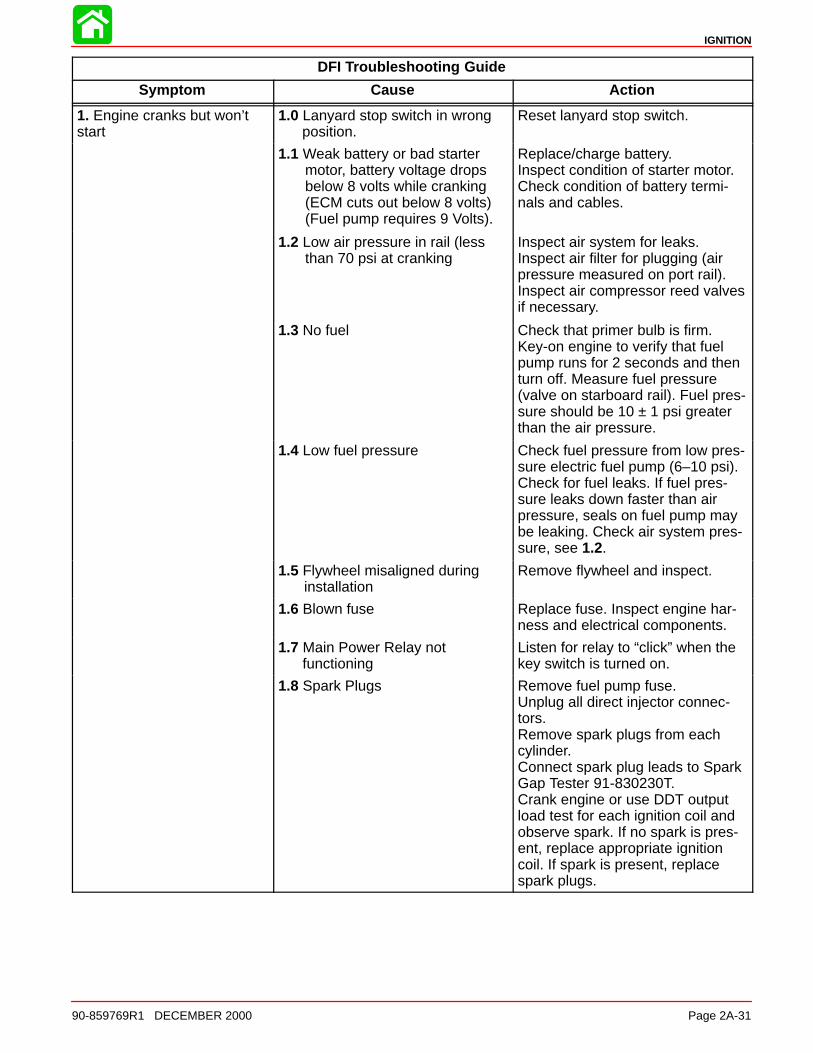
DFI Troubleshooting Guide
Symptom Cause Action
1. Engine cranks but won’tstart
1.0 Lanyard stop switch in wrong position.
Reset lanyard stop switch.
1.1 Weak battery or bad starter motor, battery voltage drops below 8 volts while cranking (ECM cuts out below 8 volts)(Fuel pump requires 9 Volts).
Replace/charge battery.Inspect condition of starter motor.Check condition of battery termi-nals and cables.
1.2 Low air pressure in rail (less than 70 psi at cranking
Inspect air system for leaks.Inspect air filter for plugging (airpressure measured on port rail).Inspect air compressor reed valvesif necessary.
1.3 No fuel Check that primer bulb is firm.Key-on engine to verify that fuelpump runs for 2 seconds and thenturn off. Measure fuel pressure(valve on starboard rail). Fuel pres-sure should be 10 ± 1 psi greaterthan the air pressure.
1.4 Low fuel pressure Check fuel pressure from low pres-sure electric fuel pump (6–10 psi).Check for fuel leaks. If fuel pres-sure leaks down faster than airpressure, seals on fuel pump maybe leaking. Check air system pres-sure, see 1.2.
1.5 Flywheel misaligned during installation
Remove flywheel and inspect.
1.6 Blown fuse Replace fuse. Inspect engine har-ness and electrical components.
1.7 Main Power Relay notfunctioning
Listen for relay to “click” when thekey switch is turned on.
1.8 Spark Plugs Remove fuel pump fuse.Unplug all direct injector connec-tors.Remove spark plugs from eachcylinder.Connect spark plug leads to SparkGap Tester 91-830230T.Crank engine or use DDT outputload test for each ignition coil andobserve spark. If no spark is pres-ent, replace appropriate ignitioncoil. If spark is present, replacespark plugs.
IGNITION
Page 2A-32 90-859769R1 DECEMBER 2000
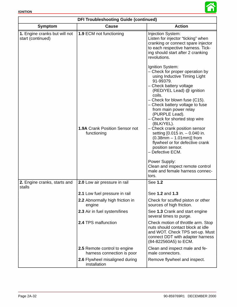
DFI Troubleshooting Guide (continued)
Symptom Cause Action
1. Engine cranks but will notstart (continued)
1.9 ECM not functioning
1.9A Crank Position Sensor not functioning
Injection System:Listen for injector “ticking” whencranking or connect spare injectorto each respective harness. Tick-ing should start after 2 crankingrevolutions.
Ignition System:– Check for proper operation by
using Inductive Timing Light91-99379.
– Check battery voltage(RED/YEL Lead) @ ignitioncoils.
– Check for blown fuse (C15).– Check battery voltage to fuse
from main power relay(PURPLE Lead).
– Check for shorted stop wire(BLK/YEL).
– Check crank position sensorsetting [0.015 in. – 0.040 in. (0.38mm – 1.01mm)] fromflywheel or for defective crankposition sensor.
– Defective ECM.
Power Supply:Clean and inspect remote controlmale and female harness connec-tors.
2. Engine cranks, starts andstalls
2.0 Low air pressure in rail See 1.2
2.1 Low fuel pressure in rail See 1.2 and 1.3
2.2 Abnormally high friction inengine
Check for scuffed piston or othersources of high friction.
2.3 Air in fuel system/lines See 1.3 Crank and start engineseveral times to purge.
2.4 TPS malfunction Check motion of throttle arm. Stopnuts should contact block at idleand WOT. Check TPS set-up. Mustconnect DDT with adapter harness(84-822560A5) to ECM.
2.5 Remote control to engineharness connection is poor
Clean and inspect male and fe-male connectors.
2.6 Flywheel misaligned during installation
Remove flywheel and inspect.
IGNITION
90-859769R1 DECEMBER 2000 Page 2A-33
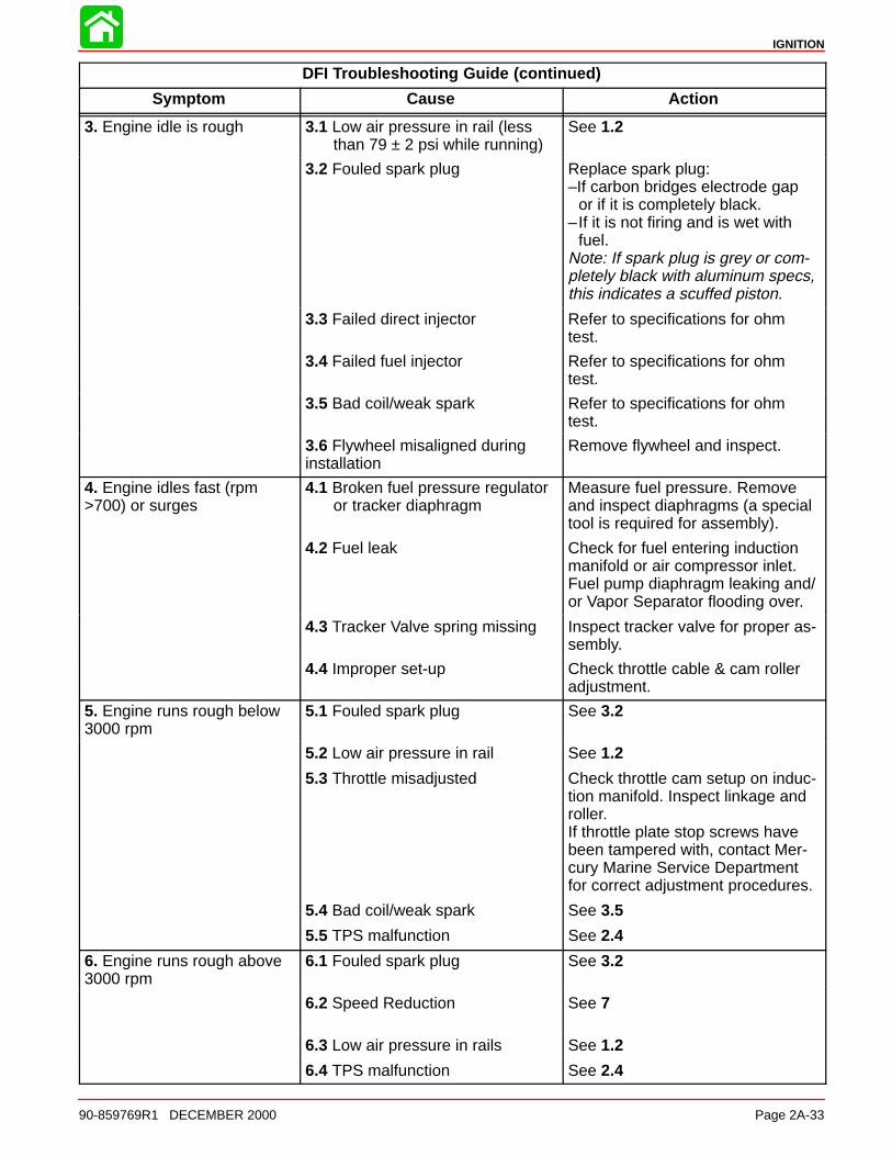
DFI Troubleshooting Guide (continued)
Symptom Cause Action
3. Engine idle is rough 3.1 Low air pressure in rail (less than 79 ± 2 psi while running)
See 1.2
3.2 Fouled spark plug Replace spark plug:–If carbon bridges electrode gap
or if it is completely black.–If it is not firing and is wet with
fuel.Note: If spark plug is grey or com-pletely black with aluminum specs,this indicates a scuffed piston.
3.3 Failed direct injector Refer to specifications for ohmtest.
3.4 Failed fuel injector Refer to specifications for ohmtest.
3.5 Bad coil/weak spark Refer to specifications for ohmtest.
3.6 Flywheel misaligned duringinstallation
Remove flywheel and inspect.
4. Engine idles fast (rpm>700) or surges
4.1 Broken fuel pressure regulator or tracker diaphragm
Measure fuel pressure. Removeand inspect diaphragms (a specialtool is required for assembly).
4.2 Fuel leak Check for fuel entering inductionmanifold or air compressor inlet.Fuel pump diaphragm leaking and/or Vapor Separator flooding over.
4.3 Tracker Valve spring missing Inspect tracker valve for proper as-sembly.
4.4 Improper set-up Check throttle cable & cam rolleradjustment.
5. Engine runs rough below3000 rpm
5.1 Fouled spark plug See 3.2
5.2 Low air pressure in rail See 1.2
5.3 Throttle misadjusted Check throttle cam setup on induc-tion manifold. Inspect linkage androller.If throttle plate stop screws havebeen tampered with, contact Mer-cury Marine Service Departmentfor correct adjustment procedures.
5.4 Bad coil/weak spark See 3.5
5.5 TPS malfunction See 2.4
6. Engine runs rough above3000 rpm
6.1 Fouled spark plug See 3.2
6.2 Speed Reduction See 7
6.3 Low air pressure in rails See 1.2
6.4 TPS malfunction See 2.4
IGNITION
Page 2A-34 90-859769R1 DECEMBER 2000
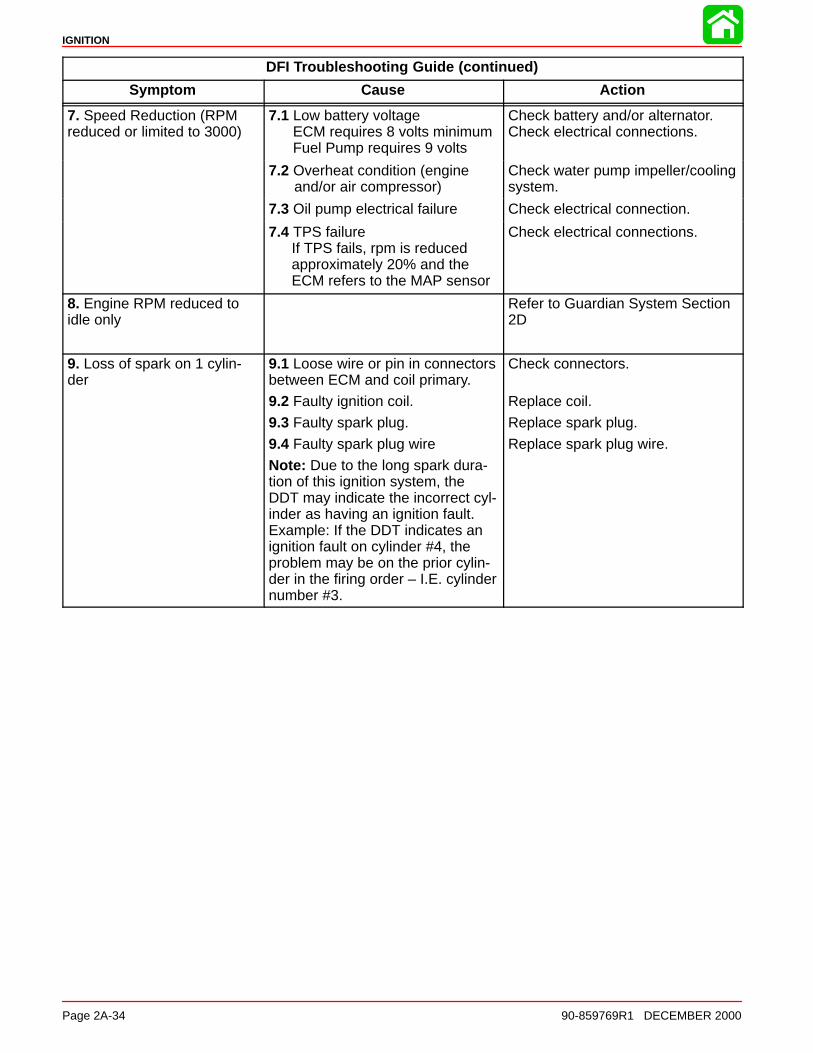
DFI Troubleshooting Guide (continued)
Symptom Cause Action
7. Speed Reduction (RPMreduced or limited to 3000)
7.1 Low battery voltageECM requires 8 volts minimumFuel Pump requires 9 volts
Check battery and/or alternator.Check electrical connections.
7.2 Overheat condition (engineand/or air compressor)
Check water pump impeller/coolingsystem.
7.3 Oil pump electrical failure Check electrical connection.
7.4 TPS failureIf TPS fails, rpm is reduced approximately 20% and the ECM refers to the MAP sensor
Check electrical connections.
8. Engine RPM reduced toidle only
Refer to Guardian System Section2D
9. Loss of spark on 1 cylin-der
9.1 Loose wire or pin in connectorsbetween ECM and coil primary.
9.2 Faulty ignition coil.
9.3 Faulty spark plug.
9.4 Faulty spark plug wire
Note: Due to the long spark dura-tion of this ignition system, theDDT may indicate the incorrect cyl-inder as having an ignition fault.Example: If the DDT indicates anignition fault on cylinder #4, theproblem may be on the prior cylin-der in the firing order – I.E. cylindernumber #3.
Check connectors.
Replace coil.
Replace spark plug.
Replace spark plug wire.
IGNITION
90-859769R1 DECEMBER 2000 Page 2A-35
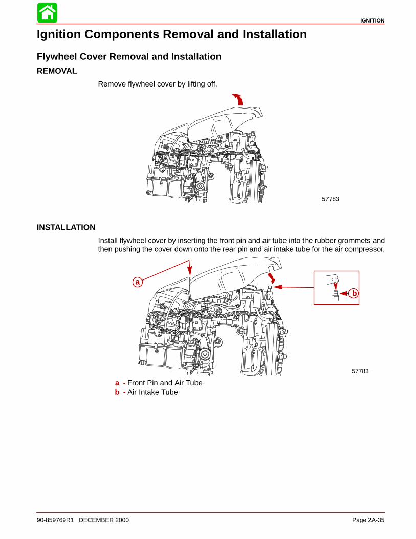
Ignition Components Removal and Installation
Flywheel Cover Removal and InstallationREMOVAL
Remove flywheel cover by lifting off.
57783
INSTALLATION
Install flywheel cover by inserting the front pin and air tube into the rubber grommets andthen pushing the cover down onto the rear pin and air intake tube for the air compressor.
57783
ab
a - Front Pin and Air Tubeb - Air Intake Tube
IGNITION
Page 2A-36 90-859769R1 DECEMBER 2000
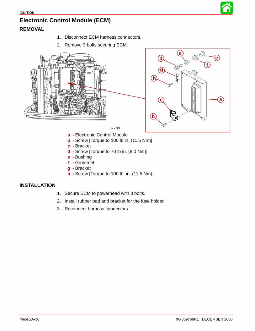
Electronic Control Module (ECM)REMOVAL
1. Disconnect ECM harness connectors.
2. Remove 3 bolts securing ECM.
a
b
f
c
de
e
g
h
57789
a - Electronic Control Moduleb - Screw [Torque to 100 lb in. (11.5 Nm)]c - Bracketd - Screw [Torque to 70 lb in. (8.0 Nm)]e - Bushingf - Grommetg - Bracketh - Screw [Torque to 100 lb. in. (11.5 Nm)]
INSTALLATION
1. Secure ECM to powerhead with 3 bolts.
2. Install rubber pad and bracket for the fuse holder.
3. Reconnect harness connectors.
IGNITION
90-859769R1 DECEMBER 2000 Page 2A-37
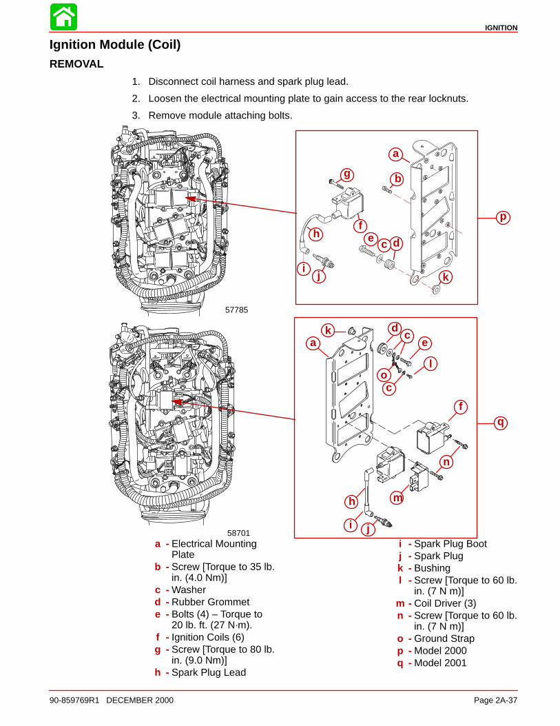
Ignition Module (Coil)REMOVAL
1. Disconnect coil harness and spark plug lead.
2. Loosen the electrical mounting plate to gain access to the rear locknuts.
3. Remove module attaching bolts.
a
b
dcef
g
h
ij
57785
dc
e
ji
h
f
k
ka
c
l
n
o
m
p
q
58701a - Electrical Mounting
Plateb - Screw [Torque to 35 lb.
in. (4.0 Nm)]c - Washerd - Rubber Grommete - Bolts (4) – Torque to
20 lb. ft. (27 N·m).f - Ignition Coils (6)g - Screw [Torque to 80 lb.
in. (9.0 Nm)]h - Spark Plug Lead
i - Spark Plug Bootj - Spark Plugk - Bushingl - Screw [Torque to 60 lb.
in. (7 N m)]m - Coil Driver (3)n - Screw [Torque to 60 lb.
in. (7 N m)]o - Ground Strapp - Model 2000q - Model 2001
IGNITION
Page 2A-38 90-859769R1 DECEMBER 2000
INSTALLATION
1. Fasten coils to electrical mounting plate as shown.
2. Reinstall electrical mounting plate.
3. Reconnect spark plug lead and coil harness.
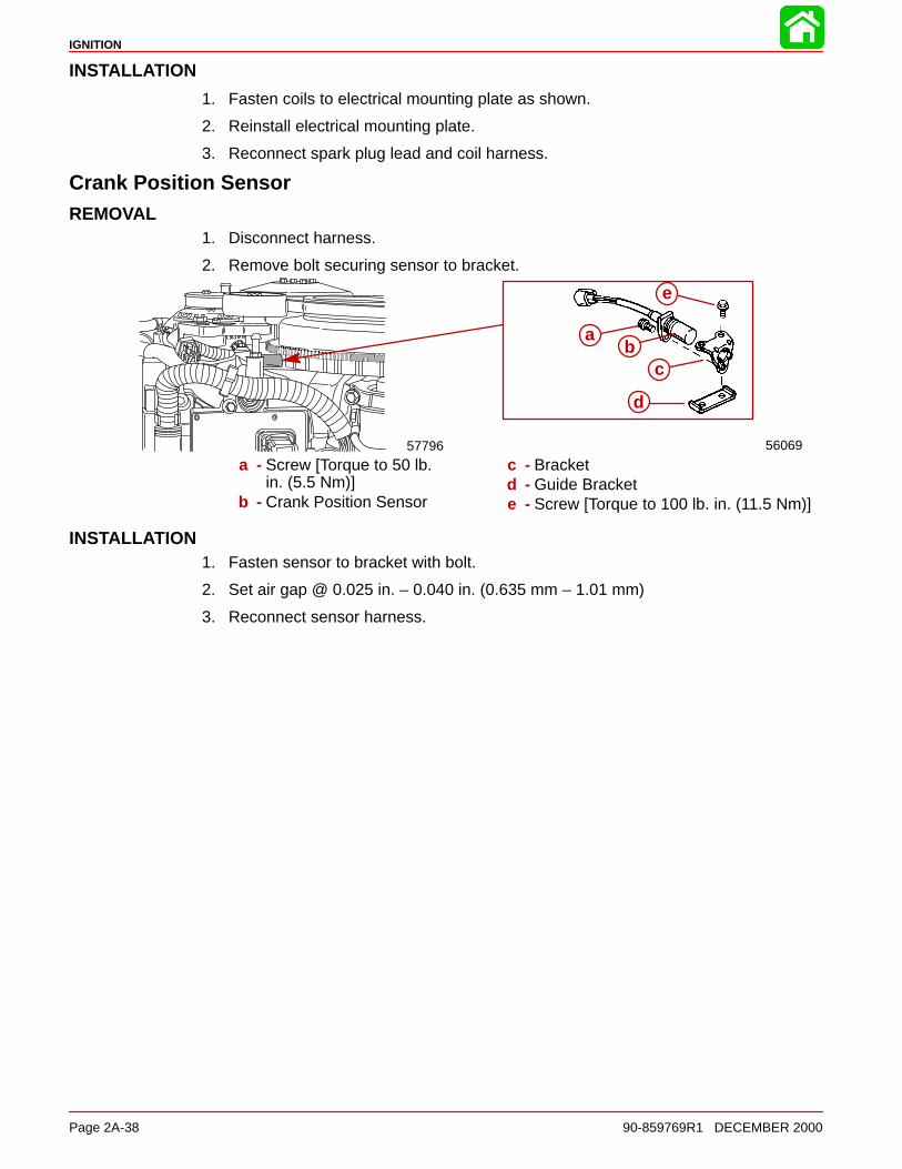
Crank Position SensorREMOVAL
1. Disconnect harness.
2. Remove bolt securing sensor to bracket.
56069
e
57796
ab
c
d
a - Screw [Torque to 50 lb.in. (5.5 Nm)]
b - Crank Position Sensor
c - Bracketd - Guide Brackete - Screw [Torque to 100 lb. in. (11.5 Nm)]
INSTALLATION1. Fasten sensor to bracket with bolt.
2. Set air gap @ 0.025 in. – 0.040 in. (0.635 mm – 1.01 mm)
3. Reconnect sensor harness.
IGNITION
90-859769R1 DECEMBER 2000 Page 2A-39
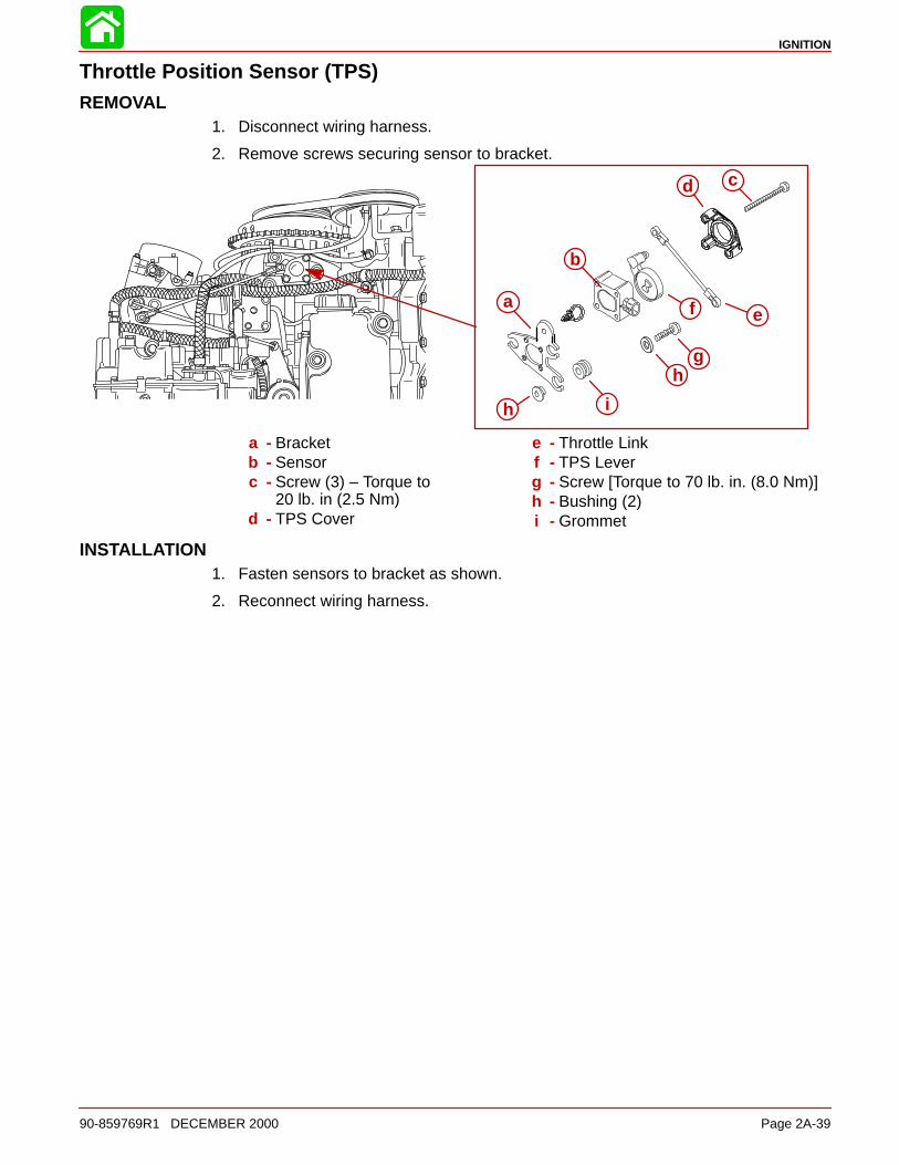
Throttle Position Sensor (TPS)REMOVAL
1. Disconnect wiring harness.
2. Remove screws securing sensor to bracket.
a
b
d
gh
i
f
c
e
h
a - Bracketb - Sensorc - Screw (3) – Torque to
20 lb. in (2.5 Nm)d - TPS Cover
e - Throttle Linkf - TPS Leverg - Screw [Torque to 70 lb. in. (8.0 Nm)]h - Bushing (2)i - Grommet
INSTALLATION1. Fasten sensors to bracket as shown.
2. Reconnect wiring harness.