Embed Size (px)
Citation preview
IGS TC-04 on Geotechnical Investigation
Constituted in March 2015 by Indian Geotechnical Society, New Delhi
IGS:TC 04 Core Members
Chairman
Prof. V.S. Raju, Former Director, IIT Delhi, [email protected]
Convener
Mr. Anirudhan I.V., Geotechnical Solutions, Chennai, [email protected]
Members
Dr. Dasaka Sathyanarayana Murthy, IIT Bombay, [email protected]
Mr. Hitesh H Desai, Unique Engineering Testing & Advisory Services, Surat, [email protected]
Dr. K Muthukkumaran, NIT Trichy, [email protected]
Prof. R.G. Robinson, IIT Madras,[email protected]
Mr. Sanjay Gupta, Cengrs Geotechnica Pvt. Ltd., [email protected]
Dr. T. Thyagaraj, IIT Madras, [email protected]
Document
PRELIMINARY DRAFT ON - A Manual of Guidance to Geotechnical Investigation
Planning, Methods, Procedures, and Reporting – 18 November 2015
A Manual of Guidance to
Geotechnical Investigation Planning, Methods, Procedures, and Reporting
Page 1 of 25
TITLE - A Manual of Guidance to Geotechnical Investigation Planning,
Methods, Procedures, and Reporting
1. Aim and Scope
1.1. The aims of this document are
a) Guiding the planner of a geotechnical investigation to decide the methods and quantum of
geotechnical investigation and for preparing a specification for carrying out the investigation
and reporting;
b) Guiding the investigation agency for following the correct procedures, correct and expressive
recording of the field and laboratory data and then for preparing the geotechnical
investigation report containing the factual investigation data and the results;
c) Guiding the geotechnical designer for interpreting and analysing the investigation results for
arriving at the characteristic values for different foundation design parameters and then for
preparing the geotechnical design report for the specific project,
d) Guiding the owner of the project / project consultant to see whether they are getting the
relevant, reliable and useful geotechnical design data and the design required for the
execution of the project, and also for
e) Guiding the owner / project consultant to select the planner, geotechnical investigation
agency and the geotechnical designer.
1.2. This manual is covering the following
a) Importance of geotechnical investigation in successful and timely completion of a project
b) Reasons for poor quality geotechnical investigation
c) Terminologies commonly used in the geotechnical investigation and reporting
d) Definitions and qualifying details of the planner, the investigation agency and the
geotechnical designer.
e) Defining the geotechnical categories (of structures) with respect to the type, size and
importance of a construction and its foundation
f) Defining the objectives of geotechnical investigation specific to the project
g) Available methods for investigation and their applications & limitations
h) Planning geotechnical investigation for different geotechnical categories
i) Preparation of detailed specification for geotechnical investigation and its reporting
j) Introduction to procedures of different investigation methods, recording the data & limitations
k) Preparation of geotechnical investigation report providing factual data from field and
laboratory, results, basic interpretations, sub-soil sections, etc.
l) Recommended terms for describing soils and rocks and their properties
m) Preparation of geotechnical design report that includes detailed interpretation of the
investigation data and results
n) Responsibilities and liabilities of planner, the investigation agency, the geotechnical designer
and the owner/project consultants.
o) Short listing of the planner, the investigation agency and the geotechnical designer.
p) The guide is not, however, providing detailed procedures of geotechnical investigation since
those are available in literature and also there are relevant BIS Codes of practices.
A Manual of Guidance to
Geotechnical Investigation Planning, Methods, Procedures, and Reporting
Page 2 of 25
2. Importance of Geotechnical Investigation in Successful and Timely Completion of a Project
2.1. The complex nature of sub-soil formations makes it difficult to assume uniformity or similarity in
the sub-stratum even between two nearby locations. The shear strength (load carrying capacity) and
compressibility (yielding of soil under expected load) vary significantly in the vertical as well as in
the horizontal directions. The information on shear strength, compressibility and their variations
are critical for designing a foundation or any structure below ground surface. There are also other
important parameters such as the dynamic properties of soil that can define the capability of soil to
sustain dynamic and seismic loads, capability for drainage, suitability for the reuse of the soil for
other purposes, etc. Sometime, the ground is poor for supporting a structure and there are ways and
means for improving the soil to suit the purpose. Deep excavations are often needed for developing
extra space below the ground, especially for infrastructure development, and these excavations are
to be made stable by selecting a suitable retention system. Design of these improvement procedure
and retention systems also requires adequate understanding of the characteristics of different soil
layers to varying depths.
2.2. These important geotechnical parameters can be obtained only through a quality geotechnical
investigation using standard equipment frequently calibrated and maintained. It is also important
to plan these investigations to suit the requirement that would largely depend on the type of
construction or development and also on the sub-soil conditions present in the site.
2.3. Inadequate knowledge of ground in which the construction is being made often leads to changes in
the foundation system, excavation procedures, construction procedures, etc. resulting in large cost
overruns. Poor geotechnical investigations in major infrastructure and industrial projects are
resulting in project delays and cost escalation.
3. Reasons for Poor Quality Geotechnical Investigation
3.1. In general, the quality of geotechnical investigations in India is poor and there is a need to improve
the quality to certain standard so that the purpose of such investigation is served. Knowing the root
causes for poor / inadequate geotechnical investigation will help in improving the quality.
3.2. The root causes for poor investigation can be listed as below:
a) The absence of any quality control enforcement in the site as well as in the laboratory
b) Lack of internal quality assurance procedures and controls by the investigation
company
c) Lack of training to the site and laboratory investigation team
d) Improper and inadequate maintenance of testing tools
e) Reluctance to adopt advanced procedures wherever necessary
f) Lack of co-ordination between the planner, the designer & the investigation team
g) Improper planning of geotechnical investigation
h) Selection of wrong procedures and tests and improper specifications
i) Poor allocation of funds for geotechnical investigation
j) Selection of investigation agency on the basis of lowest bid irrespective of the
credence of the agency
k) No knowledge of actual credentials of the investigation team
l) Unrealistic time schedule for geotechnical survey
m) Poor demand for good geotechnical investigation, and
n) Wrong and obsolete provisions in the codes of practices
o) Lack of proper legal framework for fixing responsibility on erring agency, ex. on
client, consultant, soil investigation agency, etc.
A Manual of Guidance to
Geotechnical Investigation Planning, Methods, Procedures, and Reporting
Page 3 of 25
p) Lack of defined limits of liability for each of the stakeholders (client, project
consultant, investigation agency, design consultant, etc.) on cost and time effects due
to inherent variability of soil parameters.
3.3. The first five reasons are to be addressed by the geotechnical investigation agencies even though
the factors like poor allocation of funds, improper planning, unrealistic time schedule, etc. are
contributing factors that affect the adequacy and quality of the investigation. Demand for good
geotechnical investigation will definitely make the owner to allocate for more funds, proper
selection of the investigation agency and asking for proper specifications from the planners.
4. Terminologies Commonly used in the Geotechnical Investigation and Reporting
4.1. Several terms are in practice for describing the geotechnical investigation. ‘Site Investigation’,
‘Sub-surface Exploration’, ‘Soil Investigation’, ‘Geotechnical Investigation’, ‘Sub-soil
Characterization’, ‘Ground Investigation’, etc. are some of the terms in use.
4.2. In several instances, the term ‘subsurface exploration’ is being referred as a part of ‘site
investigation’. Often the investigation has to extend beyond the soil layer exploring the intermediate
geo-material and weathered and sound rock. Considering these factors, it is recommended to use
the terms ‘Site Investigation’ or ‘Geotechnical Investigation’. Out of these two terms,
‘Geotechnical Investigation’ may be more appropriate and preferred.
4.3. The following sub terms may be appropriate to describe various activities of Geotechnical
Investigation.
a) Desk study
b) Walkover survey
c) Geophysical investigation techniques
d) Subsurface exploration by boring, by drilling, by trial pits and by sounding
e) In-situ testing
f) Laboratory investigation / laboratory testing
5. Definitions and Qualifying Details of the Planner, the Investigation Agency and the Geotechnical
Designer
5.1. The geotechnical investigation planner may be defined as the person who plans the geotechnical
investigation programme based on the desk study of all the gathered sub-soil information of the
site, the types of structures envisaged in the project, size and spread of various structures,
importance of various structures and geotechnical activities like excavation, dewatering, slope
cutting, etc. The planner may be an architect or a structural engineer who has sufficient knowledge
in the geotechnical investigation procedures or the geotechnical consultant to the project.
It should be made mandatory to employ a Geotechnical Consultant with sufficient experience in
medium to large projects to be part of initial planning and scheduling of a project including planning
of geotechnical investigation. Inputs from architects, structural engineer and process engineers shall
be taken by the Geotechnical Consultant, wherever necessary, while planning the geotechnical
investigation.
5.2. The Geotechnical Investigation Agency may be defined as a firm or company that has all necessary
resources to carry out the geotechnical investigation prescribed by the planner. Thus the term
geotechnical investigation agency is very subjective with respect to the project in hand. The
investigation agency shall own all necessary machines, tools, test equipment, in-house testing
laboratory and all personnel trained to conduct various tests prescribed. The entire investigation
shall be overviewed by a geotechnical engineer with all necessary field and laboratory experience.
The geotechnical engineer shall be assisted by suitably trained personnel who care for the
correctness of all the testing procedures and reporting. The investigation agency is responsible for
keeping all the tools and gadgets properly and periodically calibrated and maintained.
A Manual of Guidance to
Geotechnical Investigation Planning, Methods, Procedures, and Reporting
Page 4 of 25
The geotechnical investigation agency may be allowed to appoint another specialist agency and
their equipment and personnel for carrying out special tests (not routine) after adequately notifying
the project authorities/geotechnical consultant. For examples, tests for dynamic parameters,
geophysical tests, etc.
5.3. Geotechnical designer can be an independent entity with adequate experience in interpreting the
geotechnical data and designing the foundations, excavations, ground improvement procedures,
slope cutting, retaining walls, etc. The geotechnical designer shall be equipped with all the
necessary resources like latest literature, analysing tools, computing facilities, etc. depending on
the demand of the project. The geotechnical designer can be part of the planner or even the
geotechnical investigation agency depending on the work allocation between them.
6. Defining the Geotechnical Categories (of Structures) with respect to the Type, Size and
Importance of a Construction and Its Foundation
6.1. It may be advantageous to categories the structures in terms of its geotechnical importance for
helping a proper geotechnical investigation.
a) Buildings and warehousing with light to medium loads / which tolerate moderate
settlements and that can generally be supported by shallow foundations
b) Buildings and warehousing with moderate to heavy loads / sensitive to settlements that
may call for special foundations
c) Liquid retaining structures above ground and ground supported
d) Bridges and retaining walls
e) Industrial and plant structures, stack structures and storage structures with moderate to
heavy loads / sensitive to settlements that may call for special foundations
f) Earth retaining structures
g) Dams, embankments and dykes
h) Slopes
i) Waste deposits
j) Tall towers
k) Structures in liquefiable soil conditions
6.2. There are special cases of light structures on poor and problematic soils, structures on slopes,
marine structures, etc. Runways and roads are not included in the list since these developments are
covered under MOST.
7. Defining the Objectives of Geotechnical Investigation Specific to the Project
7.1. The objectives of geotechnical investigation are well known and are generally defined in IS 1892.
A broad outline of these objectives is as below
7.2. Site selection: This is often not a choice, but there are specific instances of using geotechnical
investigation for deciding suitability of a site for specific construction. Such study is important for
dams, bridges, nuclear installations, large dykes, underground utilities, etc. Geo-environmental
factors and engineering geology play a major role in these cases.
7.3. Design of Foundations and Excavations: This is the most common objective of geotechnical
investigation in most of the projects. The investigation shall meet the requirements set-forth for
arriving at various design parameters apart from the ground water locations, subsoil stratification
profiles and its variations, etc.
7.4. Design of Temporary Work: Geotechnical investigation is needed for designing temporary works
such as retention system for an excavation for facilitating construction deep below ground level,
cofferdams for isolating areas of construction of a bridge pier or a water intake structure, lowering
ground water table, etc.
A Manual of Guidance to
Geotechnical Investigation Planning, Methods, Procedures, and Reporting
Page 5 of 25
7.5. Environmental impact by a project: There can be distress in existing structures due to the
construction of foundations or excavations for new constructions in certain soil formations.
Assessment of such impact is possible only by conducting a geotechnical investigation in the areas
that possibly may get affected.
7.6. Design of remedial works: Assessment of the causes of distress or partial failure of a structure and
then designing remedial works require geotechnical investigation that provides necessary soil
characteristics and design parameters.
7.7. Sustainability and Safety: Most of the structures are built for serving a long time. Dams and
embankments may be built to tender service for 100 or more years. The possible changes in the
ground conditions that can affect the satisfactory performance of such structures for such a long
period can be assessed by well-planned geotechnical investigation.
7.8. For use of soil as engineering or construction material: Soil is used as construction material or
engineering material in the case of dams and embankment, reinforced earth walls, lining materials
for waste fills, etc. Suitability of soil for these specific purposes is defined by adequate field and
laboratory studies.
8. Available Methods for Investigation and their Applications & Limitations
8.1. Direct procedures
8.1.1. Trial pit excavation, load testing on soils and rocks, exploratory boring and sampling, In-situ
testing and sampling in boreholes, laboratory testing procedures on disturbed and undisturbed
soil samples, self-boring pressure meters and Trial pit excavation come under this broad
category.
8.1.2. The most common in-situ testing procedures in the exploratory boreholes are i) Standard
Penetration tests (SPT), ii) Field Vane Shear Strength Tests (FVST), iii) pressure meter tests,
iv) packer tests and other types of permeability tests, v) Undisturbed sampling and vi) torque
tests. There are also other not so common procedures such as ‘T’ bar and ‘ball’ penetration
tests for soft soil deposits.
8.1.3. Sub-surface sounding by dynamic penetration of a cone (DPT and DCPT), sounding using
Static Cone Penetration Tests (SCPT, CPTU), Sounding using Dilatometer, etc. are some of
the procedures under this category.
8.2. Indirect Procedures
8.2.1. Geophysical methods are under this category. There are advanced procedures like Ground
Penetration Radar (GPR), Seismic Refraction Wave studies using geophysical formulations,
Cross Hole wave propagation studies, etc.
8.3. Procedures for Dynamic Properties of Soil and Rock
8.3.1. The standard procedures available are cyclic plate load test for large strain shear modulus and
other relevant parameters that may have use for design of certain machine foundations.
8.3.2. Block vibration tests and more advanced testing procedures like cross hole dynamic
geophysical tests, etc. are required for low strain modulus determination and other relevant
parameters like damping coefficient, etc. Energy calibrated SPT systems are also useful for
the determination of dynamic properties.
8.3.3. The laboratory procedures like resonance column tests, cyclic triaxial tests, etc. may be
needed for detailed studies.
8.4. Table 1 is providing common soil profiles, structures and suitability of different investigation
procedures.
A Manual of Guidance to
Geotechnical Investigation Planning, Methods, Procedures, and Reporting
Page 6 of 25
9. Planning Geotechnical Investigation for Different Geotechnical Categories
9.1. The requirement of geotechnical investigation is defined by,
a) The statutory requirements prevailing in the region / country,
b) Knowledge of geotechnical conditions in the area,
c) Size and importance of the project,
d) Loads and limiting settlements of various units in the project,
e) Prevailing sub-soil conditions and geology,
f) Environment, and
g) Terrain of the project land
9.2. Different phases of a geotechnical investigation may be described as below
a) Desk study and walkover survey
b) Geophysical study (Engineering geophysics)
c) Boring, drilling, probing, trial pit excavation, sampling
d) Laboratory testing
9.3. Desk study and walkover survey
9.3.1. Desk study and walkover survey shall essentially be carried out so that the adequacy of
available data is ascertained and then further course of investigation is planned. Often, this
phase of investigation may be adequate for small projects.
9.3.2. The walkover survey shall identify geological and other features of the land, such as open
well, springs, general terrain, drainage paths, sinkholes, etc. Valleys, streams, summits, rock
outcrops, contamination, etc. are of importance in the case of large projects.
9.3.3. This phase covers site topography study, geology of the site, known geotechnical problems
and parameters of the area, ground water conditions, existing constructions and services with
data on the foundations adopted, previous land use, meteorological data, etc. The
recommendations based on the study during this phase shall form the basis for planning
further geotechnical investigation, if necessary.
9.3.4. Unfortunately, in India, the geotechnical and geological data and topographical data are not
readily available for use. The information on the type of foundation used for other
construction is also not readily available. Development of such data bank operated by a
responsible body shall be started and such data bank shall improve the geotechnical
investigation quality.
It is worthwhile approaching Government for making it mandatory to submit a copy of
geotechnical report comprising of all data, etc. to an approved authority or data bank such as
NIC. User can pay a token fee to collect the data, but for the limited purpose of desk studies
under the user’s risk and liability.
9.4. Geophysical study (Engineering geophysics)
9.4.1. Geophysical study or engineering geophysics may be the most useful procedure in
geotechnical investigation since such study can cover very large soil mass compared to trial
boring, probing, etc. A thorough geophysical study along with limited boring and probing
shall provide complete data of the ground.
Some of the common geophysical methods are listed below.
a) Electrical resistivity traversing
b) Gravity surveying
A Manual of Guidance to
Geotechnical Investigation Planning, Methods, Procedures, and Reporting
Page 7 of 25
c) Magnetometry
d) Ground conductivity
e) Natural gamma logging
f) Seismic down-hole logging
g) Cross hole seismic logging
h) Surface wave techniques
i) Seismic tomography
j) Seismic reflection
k) Seismic refraction
9.4.2. Presently, geophysical procedures as a major geotechnical investigation are not practiced.
Certain geophysical procedures (for example, f, g and h) may be made mandatory where the
dynamic properties of soil are required for the design of foundation.
This should be made mandatory for important projects and liner projects such as metros,
elevated express ways, bridges, etc. and drillings may be made only at selected locations.
Very often bridge piers are shifted to locations where there is no soil data.
9.5. Boring, drilling, probing, trial pit excavation, sampling
9.5.1. This phase is the bulk of most of geotechnical investigations today. These are considered as
direct procedures in geotechnical investigation. Boring and drilling are coupled with
sampling and in-situ testing at necessary intervals. Coring in drill holes using double core or
triple core barrels often produces rock core samples with its weathering and jointing intact.
The in-situ tests in exploratory boreholes include Standard Penetration Test, Field vane shear
test, field permeability test, undisturbed sampling, torque tests, etc.
9.5.2. Probing methods have developed significantly. Electronically operated static cone
penetration tests with piezo cone tips can measure pore water pressure and its dissipation,
thereby identifying the type of soil through which the cone is penetrating. This is a very
significant step forward since the errors are minimized. For the same reason repeatability is
high and more consistent classification systems could be evolved from these procedures.
9.5.3. Dilatometers also made significant progress in its sensitivity and measuring & recording
capabilities. These probing tools along with geophysical procedures can produce much
reliable geotechnical data.
9.6. Laboratory Testing
9.6.1. Geotechnical engineering design procedure is now equipped with several software tools
based on finite difference and finite element procedures. These procedures use different soil
models depending upon the problem in hand. The numerical procedures thus call for several
parameters that are developed from good quality laboratory testing procedures. Requirement
of good quality undisturbed samples needs to be emphasized for carrying out the basic index
property tests to more advanced tests.
9.6.2. The need for these advanced design parameters that would define the relevant soil model to
be used in the numerical analysis shall be identified during the planning of geotechnical
investigation so that a meaningful sampling programme can be implemented at site.
9.6.3. The pre-requisite for laboratory investigation is the collection of good quality representative
disturbed and undisturbed samples from different elevations and from different strata. The
quality of samples collected through augur cutting is poor because of mixing of soil from
different levels and from natural seams present in the formation. Disturbed samples from SPT
sampling have medium quality provided the sample is collected without loosing its texture
and fabric. It is mandatory to collect two or more different samples from one sampling
operation in different containers.
A Manual of Guidance to
Geotechnical Investigation Planning, Methods, Procedures, and Reporting
Page 8 of 25
There are adequate evidences for varying laboratory classification test results because of
oxidation, drying, drying and wetting, etc. It is hence necessary to bring the samples to the
laboratory in a state as natural as possible.
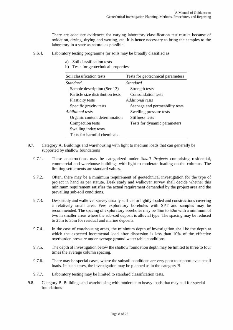
9.6.4. Laboratory testing programme for soils may be broadly classified as
a) Soil classification tests
b) Tests for geotechnical properties
Soil classification tests Tests for geotechnical parameters
Standard
Sample description (Sec 13)
Particle size distribution tests
Plasticity tests
Specific gravity tests
Additional tests
Organic content determination
Compaction tests
Swelling index tests
Tests for harmful chemicals
Standard
Strength tests
Consolidation tests
Additional tests
Seepage and permeability tests
Swelling pressure tests
Stiffness tests
Tests for dynamic parameters
9.7. Category A. Buildings and warehousing with light to medium loads that can generally be
supported by shallow foundations
9.7.1. These constructions may be categorized under Small Projects comprising residential,
commercial and warehouse buildings with light to moderate loading on the columns. The
limiting settlements are standard values.
9.7.2. Often, there may be a minimum requirement of geotechnical investigation for the type of
project in hand as per statute. Desk study and walkover survey shall decide whether this
minimum requirement satisfies the actual requirement demanded by the project area and the
prevailing sub-soil conditions.
9.7.3. Desk study and walkover survey usually suffice for lightly loaded and constructions covering
a relatively small area. Few exploratory boreholes with SPT and samples may be
recommended. The spacing of exploratory boreholes may be 45m to 50m with a minimum of
two in smaller areas where the sub-soil deposit is alluvial type. The spacing may be reduced
to 25m to 35m for residual and marine deposits.
9.7.4. In the case of warehousing areas, the minimum depth of investigation shall be the depth at
which the expected incremental load after dispersion is less than 10% of the effective
overburden pressure under average ground water table conditions.
9.7.5. The depth of investigation below the shallow foundation depth may be limited to three to four
times the average column spacing.
9.7.6. There may be special cases, where the subsoil conditions are very poor to support even small
loads. In such cases, the investigation may be planned as in the category B.
9.7.7. Laboratory testing may be limited to standard classification tests.
9.8. Category B. Buildings and warehousing with moderate to heavy loads that may call for special
foundations
A Manual of Guidance to
Geotechnical Investigation Planning, Methods, Procedures, and Reporting
Page 9 of 25
9.8.1. These constructions also come under the category of Small Projects, but comprising
residential, commercial and warehouse buildings with moderate to heavy loading on the
columns. The limiting settlements are standard values.
9.8.2. Desk study and walkover survey alone may not suffice here. Few exploratory boreholes with
SPT and samples may be recommended. The spacing of exploratory boreholes may be 40m
to 45m with a minimum of two in smaller areas where the sub-soil deposit is alluvial type.
The spacing may be reduced to 20m to 25m for residual and marine deposits.
9.8.3. The depth of investigation shall be sufficiently below the suitable bearing stratum for deep
foundations. In the case of residual deposits followed by weathered rock / rock stratum, the
investigation shall confirm the continuance of weathered rock / rock. In the case of rock
socketed piles, the depth of investigation shall extend three times the pile diameter below the
expected termination level. Diamond core drilling shall be implemented here. In the case of
piles resting in intermediate geo-material, the boreholes may be terminated at weathered rock
level. The SPT sampler shall record no penetration into such formation at the termination
level.
9.8.4. In the case of alluvial or marine deposits where the bearing stratum is dense / stiff to hard
soil, the depth of investigation shall extend to a depth equal to 10 times the expected pile
diameter or three times the encompassing width of the group of maximum number of piles.
The depth of geotechnical study may be limited to the level of weathered rock stratum with
SPT rebound, if occurring earlier.
9.8.5. Laboratory testing may be limited to standard classification tests and also the tests for harmful
chemical such as sulphate, chloride and pH determination.
9.9. Category C. Liquid retaining structures above ground and ground supported
9.9.1. Small to very large size liquid retaining structures are common in most of the industrial plants.
There are large tank farms specifically meant for storage and handling. Small to medium size
tanks with height / base ratio more than 1 are common, while the large diameter tanks usually
have height / base ratio smaller than 1.
9.9.2. The foundation for elevated storage tank shall comply the limiting total and differential
settlement requirements similar to conventional buildings and structures. The critical element
here may be the supporting structure, either RCC or steel. There are also requirements of air
circulation below the tank base in certain cases for which the tanks have to be elevated.
Geotechnical investigation for such structures may follow the category under category E
below.
9.9.3. The RC tanks shall also comply with similar requirements and in this case also the
geotechnical investigation may follow the category under category E below.
9.9.4. The ground supported MS storage tanks having flexible base are allowed relatively larger
settlements depending on the type of roofing and height / base ratio. Differential settlement
along the tank periphery and overall tilt of the tank base are the critical parameters here. The
limiting differential settlements are governed by the stresses in the shell and base plate, while
the overall tilt is restricted by the roof structure and final calibration. These limits are much
smaller than the triggering values for a base failure.
9.9.5. The foundations of storage tanks with flexible base are either improved ground or natural
ground depending on the shear strength and compressibility profiles within the respective
influence zones. These profiles are best represented by advanced probing procedures like
CPTU or dilatometer supplemented by exploratory boring and associated field testing and
sampling.
A Manual of Guidance to
Geotechnical Investigation Planning, Methods, Procedures, and Reporting
Page 10 of 25
9.9.6. The spacing of test locations may be governed by the height / base ratio and the base diameter
/ dimensions. The following criteria may be followed for deciding the number of test
locations.
a) For diameter less than or equal to 8 m and H/B ratio less than 1 – one or two test
locations
b) For diameter more than 8 m – Minimum 3 test locations along the periphery, but
with spacing not more than 25m when H/B ratio ≤ 1. The spacing shall be reduced to
25 x B/H for the tanks with H/B ratio >1.
c) Additional borehole in the centre of the tank when the tank diameter is more than
35m.
d) Geophysical methods for highly varying sub-soil profiles
9.9.7. The depth of investigation shall be equal to a depth at which the incremental stress after
dispersion is less than 10% of the effective overburden pressure under average water table
conditions.
9.9.8. Laboratory testing may comprise standard classification tests and standard tests for
geotechnical parameters.
9.10. Category D. Bridges and retaining walls
9.10.1. The geotechnical investigation requirements for bridge structure may follow the latest MOST
guidelines to avoid conflicts.
9.10.2. The RE walls can tolerate relatively large differential settlements. However, the limits may
be stringent depending up on the fascia so that the fascia elements are not dislocated. RC
retaining walls shall generally follow the limits prescribed in IS 1904.
9.10.3. Exploratory boreholes with relevant field testing and sampling shall be prescribed for every
30m to 35m of the wall length having height more than 4m. The depth of investigation may
be maximum of the following.
a) Depth equal to twice the width of reinforced earth section
b) If soft or loose deposits continue below the depth prescribed above, two or three
metres below the thickness of loose / weak soil
9.10.4. Laboratory testing may comprise standard classification tests and standard tests for
geotechnical parameters.
9.11. Category E. Industrial and plant structures, stack structures and storage structures with moderate to
heavy loads that may call for special foundations
9.11.1. Desk study and walkover survey shall decide the total scope of geotechnical investigation.
Geophysical methods may preferably be employed in the case of residual and tropical soils.
9.11.2. Direct methods like exploratory boring / drilling and trial pitting may be employed in the
preliminary phase of investigation as supplement to the desk study and walkover survey. The
number of settings may be with large spacing such as 200m to 300m in this initial phase. The
initial phase of investigation data shall provide the following information apart from the
general soil profile data.
a) Whether the soil is liquefiable or not and the likely depth of liquefaction
b) Whether ground improvement procedures are necessary or not
c) Requirement of deep foundations and the expected range of depths
d) Likelihood of drag force on deep foundation
e) Precautions against chemical attach on foundations
A Manual of Guidance to
Geotechnical Investigation Planning, Methods, Procedures, and Reporting
Page 11 of 25
9.11.3. The number of exploratory borings and other test procedures in the detailed investigation
stage depend on different units in the plant and the type of sub-soil and its variations. The
filed procedures shall include exploratory boreholes with core drilling if the bearing stratum
is weathered rock or rock. There shall be CPTU and continuous SPT boreholes if the soil is
liquefiable or if the ground requires improvement. Undisturbed sampling in soft to medium
deposits is mandatory.
9.11.4. Geophysical procedure and other dynamic testing procedures shall be included if the
foundations are subjected to dynamic loads. Seismic response studies are important in the
earth quake zones IV and V.
9.11.5. The depth of investigation shall be sufficiently below the suitable bearing stratum for deep
foundations. In the case of residual deposits followed by weathered rock / rock stratum, the
investigation shall confirm the continuance of weathered rock / rock. In the case of rock
socketed piles, the depth of investigation shall extend three times the pile diameter below the
expected termination level. Diamond core drilling shall be implemented here. In the case of
piles resting in intermediate geo-material, the boreholes may be terminated at weathered rock
level. The SPT sampler shall record no penetration into such formation at the termination
level.
9.11.6. In the case of alluvial or marine deposits where the bearing stratum is dense / stiff to hard
soil, the depth of investigation shall extend to a depth equal to 10 times the expected pile
diameter or three times the encompassing width of the group of maximum number of piles.
The depth of geotechnical study may be limited to the level of weathered rock stratum with
SPT rebound, if occurring earlier.
9.11.7. Laboratory testing may be limited to standard classification tests and also the tests for harmful
chemical such as sulphate, chloride and pH determination. Standard tests for geotechnical
parameters shall be mandatory where soft / medium stiff deposits are present.
9.12. Category F. Earth retaining structures (to be expanded)
9.13. Category G. Dams, embankments and dykes (to be expanded)
9.14. Category H. Slopes (to be expanded)
9.15. Category I. Waste deposits (to be expanded)
9.16. Category J. Tall towers (to be expanded)
9.17. Category K. Structures in liquefiable soil conditions (to be expanded)
10. Preparation of Detailed Specification for Geotechnical Investigation and its Reporting (To be
expanded)
11. Introduction to Procedures of Different Investigation Methods, Recording the Data &
Limitations
11.1. Standard Penetration Test (SPT)
11.1.1. One of the most common in-situ tests is the standard penetration test, or commonly termed
as SPT. This test was originally developed in the late 1920s and has been extensively used
for characterization of soils. Because of this long record of experience, simplicity and low
cost, the test is well established in geotechnical engineering practice.
11.1.2. The test procedure involves drilling a bore hole to the depth of investigation and driving a
SPT sampler (also known as a split-spoon sampler) into the borehole. Driving is done with a
63.5 kg hammer dropped from a height of 760 mm, using either a rope and cathead
arrangement or an automatic tripping mechanism. The procedure is repeated until the sampler
has penetrated a depth of 450 mm. The number of hammer blows required for each 150 mm

A Manual of Guidance to
Geotechnical Investigation Planning, Methods, Procedures, and Reporting
Page 12 of 25
interval is recorded. The test is stopped if more than fifty blows are required for any of the
intervals, or if more than one hundred total blows are recorded. These conditions are known
as refusal and are recorded on the boring log. The borehole is then advanced to the next depth
and the procedure is repeated up to the depth of investigation.
11.1.3. The following aspects are recorded in a SPT test:
(i) Site name
(ii) Borehole number
(iii) Sample number
(iv) Date of test
(v) Method of boring
(vi) Diameter of borehole
(vii) Fluid level in the borehole
(viii) Depth of borehole and depth of test below the ground level
(ix) Hammer type
(x) Initial penetration under self-weight
(xi) Number of blows
(xii) Length of sample recovered
(xiii) Soil description
11.1.4. The SPT test has application in almost all types of soils, though ideally suitable for granular
soils. The test can be also used in sites containing hard soils which are difficult to sample.
One of the major advantages of SPT is that a disturbed sample is collected in the split spoon
for inspection, testing and classification. The results are also available immediately after the
test for interpretation. The test can be carried out in routine exploration boreholes so that there
is no need of sophisticated drilling rigs. Many correlations are available with engineering
properties of soils.
11.1.5. The SPT test suffers from the following disadvantage:
Differences in boring, equipment and test procedure influence the SPT N value
requiring corrections
The energy transfer is not clear
The correlations with properties of clays is very poor
The test is conducted at discrete points
Disturbance due to driving
11.2. Cone Penetration Test (CPT)
11.2.1. The Cone Penetration Test or CPT, is another common in-situ test. Two types of cones are
commonly used: the mechanical cone and the electric cone. Both have two parts, a 35.7-mm
diameter cone-shaped tip with a 60° apex angle and a 35.7 mm diameter × 133.7 mm long
cylindrical sleeve. A hydraulic ram pushes this assembly into the ground and instruments
measure the resistance to penetration. The cone resistance, qc' is the total force acting on the
cone divided by the projected area of the cone (10 cm2): and the cone sleeve friction (fsc) is
the total frictional force acting on the friction sleeve divided by its surface area (150 cm2). It
is common to express the sleeve friction in terms of the friction ratio, Rf, which is equal to (fsc
/qc) x 100%.
11.2.2. The operation of the two types of cones differs in that the mechanical cone is advanced in
stages and measures qc and fsc at intervals of about 20 cm, whereas the electric cone includes
built-in strain gauges and is able to measure qc and fsc continuously with depth. In either case,
the CPT defines the soil profile with much greater resolution than does the SPT. CPT rigs are
A Manual of Guidance to
Geotechnical Investigation Planning, Methods, Procedures, and Reporting
Page 13 of 25
often mounted in large trucks, which can generate thrusts of 10 to 20 tons (100-200 kN).
Smaller, trailer-mounted or truck-mounted rigs also are available.
11.2.3. The CPT is becoming increasingly popular and useful to the practicing engineers. Cones
equipped with pore pressure transducers were recently developed in order to measure the
excess pore water pressures that develop while conducting the test. These are known as
piezocones, and the enhanced procedure is known as a CPTU test. These devices promise to
be especially useful in saturated clays. The pore pressure developed during the test is useful
in evaluating the coefficient of consolidation and coefficient of permeability.
11.2.4. CPT is very useful to evaluate soil profiles. Since it retrieves data continuously with depth
(with electric cones) or at very close intervals (with mechanical cones), the CPT is able to
detect fine changes in the stratigraphy. Therefore, engineers often use the CPT in the first
phase of subsurface investigation, saving boring and sampling for the second phase. The CPT
also can be used to assess the engineering properties of the soil through the use of empirical
correlations. Correlations are also available to directly relate CPT results with foundation
behavior. These are especially useful in the design of deep foundations. One of the other
applications of the CPT is for soil classification and description of soil strata. Typically, the
cone resistance qc is high in sandy soils and low in clayey soils and the friction ratio Rf is
low in sandy soils and high in clayey soils. This aspect along with the pore pressure ratio is
used for soil classification.
11.2.5. Although the CPT has many advantages over the SPT, there are at least three important
disadvantages:
No soil sample is recovered, so there is no opportunity to inspect the soils.
The test is unreliable in soils with significant gravel content.
Special rig is required to perform the CPT.
11.3. Vane Shear Test (VST)
11.3.1. The vane shear test (VST) was developed in the 1920s to carry out in-situ test on sensitive
Scandinavian marine clays. The test consists of inserting a four-blade metal vane of cruciform
shape, into the soil, and rotating it until the soil fails in shear. The vane is rotated at a rate of
6 degrees per minute. The torque required to rotate the vane is measured and is related to the
undrained shear strength of soils. The vane can be advanced to deeper depths by simply
pushing it deeper (especially in softer soils) or the test can be performed below the bottom of
a boring. However, because the vane must be thin to minimize soil disturbance, it is only
strong enough to be used in soft to medium cohesive soils. The test is performed rapidly and
therefore measures only the undrained strength.
11.3.2. Following records are made during the test:
(i) Name of Project
(ii) Bore-hole No., Date, Location, etc.
(iii) Reference elevation or Ground elevation:
(iv) Method of making the hole (Cased or uncased)
(v) Level of water in the bore-hole
(vi) Level of ground water at the time of test:
(vii) Driving resistance, if observed
(viii) Size of the vane
(ix) Conversion factor of the torque measuring equipment, etc.
11.3.3. Vane shear test is commonly conducted on saturated clay deposits. Sensitivity of the clay can
be measured by rotating the vane rapidly after reaching the peak torque. It is ideally suitable
for soft clays for which sampling is difficult.
A Manual of Guidance to
Geotechnical Investigation Planning, Methods, Procedures, and Reporting
Page 14 of 25
11.3.4. Many factors affect the vane shear test results such as:
Type of soil and its permeability
Anisotropy in strength
Effect of disturbance due to insertion of the vane
Strain rate effects, etc.
11.4. Pressuremeter Test (PMT)
11.4.1. Pressuremeter is a cylindrical balloon that is inserted into the ground and inflated.
Measurements of volume and pressure can be used to evaluate the in-situ stress,
compressibility, and strength of the adjacent soil and thus the behavior of a foundation. The
PMT may be performed in a carefully drilled boring or the test equipment can be combined
with a small auger to create a self-boring pressuremeter. The latter design provides less soil
disturbance and more intimate contact between the pressuremeter and the soil.
11.4.2. The PMT produces much more direct measurements of soil compressibility and lateral
stresses than do the SPT and CPT. Thus, in theory, it should form a better basis for settlement
analyses, and possibly for pile capacity analyses. However, the PMT is a difficult test to
perform and is limited by the availability of the equipment and personnel trained to use it.
Although the PMT is widely used in France and Germany, it is used only occasionally in
other parts of the world.
11.5. Dilatometer Test (DMT)
11.5.1. The dilatometer consists of a 95-mm wide, 15-mm thick metal blade with a thin, flat, circular,
expandable steel membrane on one side. The dilatometer test (DMT) is conducted by pushing
the dilatometer into the soil to the desired depth using a CPT rig or some other suitable device.
The membrane is expanded outwards by applying nitrogen gas. The pressure required to
move the center of the membrane to 0.05 mm (the A pressure) and 1.1 mm (the B pressure)
are measured. The membrane is then depressurized and the pressure acting on the membrane
when it returns to its original position is recorded (C pressure), which is a measure of the pore
water pressure in the soil. The dilatorneter is then advanced 150 to 300 mm deeper into the
ground and the test is repeated. The process is continued until reaching the desired depth.
11.5.2. The DMT can be used for soil classification, estimation of coefficient of lateral earth pressure,
Overconsolidation Ratio and Soil Modulus can be determined through correlations with
pressures A, B and C.
11.6. Comparison of In-Situ Test Methods
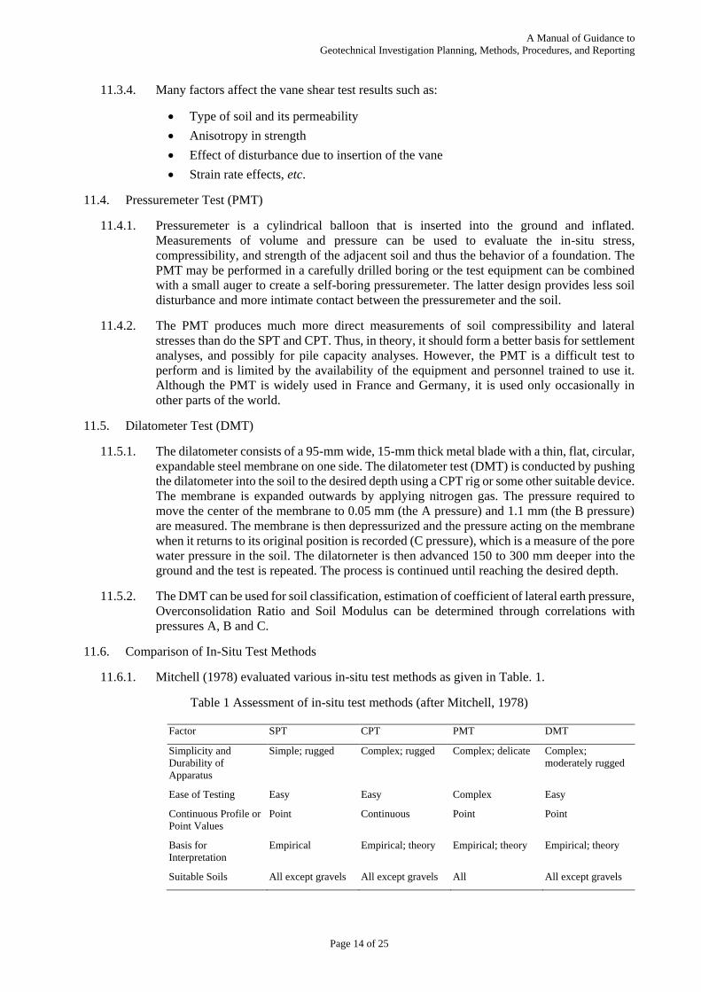
11.6.1. Mitchell (1978) evaluated various in-situ test methods as given in Table. 1.
Table 1 Assessment of in-situ test methods (after Mitchell, 1978)
Factor SPT CPT PMT DMT
Simplicity and
Durability of
Apparatus
Simple; rugged Complex; rugged Complex; delicate Complex;
moderately rugged
Ease of Testing Easy Easy Complex Easy
Continuous Profile or
Point Values
Point Continuous Point Point
Basis for
Interpretation
Empirical Empirical; theory Empirical; theory Empirical; theory
Suitable Soils All except gravels All except gravels All All except gravels
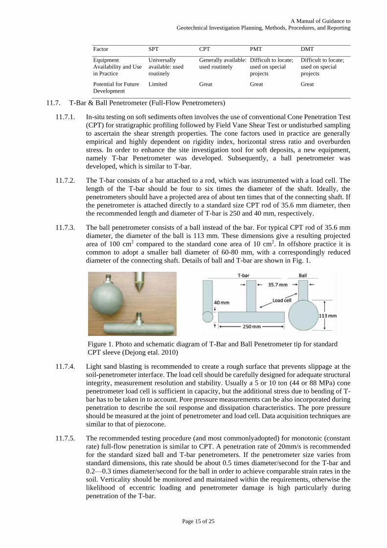
A Manual of Guidance to
Geotechnical Investigation Planning, Methods, Procedures, and Reporting
Page 15 of 25
Factor SPT CPT PMT DMT
Equipment
Availability and Use
in Practice
Universally
available: used
routinely
Generally available:
used routinely
Difficult to locate;
used on special
projects
Difficult to locate;
used on special
projects
Potential for Future
Development
Limited Great Great Great
11.7. T-Bar & Ball Penetrometer (Full-Flow Penetrometers)
11.7.1. In-situ testing on soft sediments often involves the use of conventional Cone Penetration Test
(CPT) for stratigraphic profiling followed by Field Vane Shear Test or undisturbed sampling
to ascertain the shear strength properties. The cone factors used in practice are generally
empirical and highly dependent on rigidity index, horizontal stress ratio and overburden
stress. In order to enhance the site investigation tool for soft deposits, a new equipment,
namely T-bar Penetrometer was developed. Subsequently, a ball penetrometer was
developed, which is similar to T-bar.
11.7.2. The T-bar consists of a bar attached to a rod, which was instrumented with a load cell. The
length of the T-bar should be four to six times the diameter of the shaft. Ideally, the
penetrometers should have a projected area of about ten times that of the connecting shaft. If
the penetrometer is attached directly to a standard size CPT rod of 35.6 mm diameter, then
the recommended length and diameter of T-bar is 250 and 40 mm, respectively.
11.7.3. The ball penetrometer consists of a ball instead of the bar. For typical CPT rod of 35.6 mm
diameter, the diameter of the ball is 113 mm. These dimensions give a resulting projected
area of 100 cm2 compared to the standard cone area of 10 cm2. In offshore practice it is
common to adopt a smaller ball diameter of 60-80 mm, with a correspondingly reduced
diameter of the connecting shaft. Details of ball and T-bar are shown in Fig. 1.
Figure 1. Photo and schematic diagram of T-Bar and Ball Penetrometer tip for standard
CPT sleeve (Dejong etal. 2010)
11.7.4. Light sand blasting is recommended to create a rough surface that prevents slippage at the
soil-penetrometer interface. The load cell should be carefully designed for adequate structural
integrity, measurement resolution and stability. Usually a 5 or 10 ton (44 or 88 MPa) cone
penetrometer load cell is sufficient in capacity, but the additional stress due to bending of T-
bar has to be taken in to account. Pore pressure measurements can be also incorporated during
penetration to describe the soil response and dissipation characteristics. The pore pressure
should be measured at the joint of penetrometer and load cell. Data acquisition techniques are
similar to that of piezocone.
11.7.5. The recommended testing procedure (and most commonlyadopted) for monotonic (constant
rate) full-flow penetration is similar to CPT. A penetration rate of 20mm/s is recommended
for the standard sized ball and T-bar penetrometers. If the penetrometer size varies from
standard dimensions, this rate should be about 0.5 times diameter/second for the T-bar and
0.2—0.3 times diameter/second for the ball in order to achieve comparable strain rates in the
soil. Verticality should be monitored and maintained within the requirements, otherwise the
likelihood of eccentric loading and penetrometer damage is high particularly during
penetration of the T-bar.

A Manual of Guidance to
Geotechnical Investigation Planning, Methods, Procedures, and Reporting
Page 16 of 25
11.7.6. Remolded penetration resistance can be also evaluated by cycling the penetrometer vertically,
at a constant rate, a minimum of ten times with one cycle being defined as both penetration
and extraction. Strength degradation occurs with each subsequent cycle until the soil reaches
a remolded condition at which time further cycling will cause minimal reduction in strength.
Remolded penetration resistance is defined as the average of penetration and extraction after
ten cycles. Using this data the sensitivity of the strata can be evaluated.
11.7.7. Penetration of T-bar and ball penetrometer in soft sediments induces plastic flow of soil
around the probes with minor volume displacement from the shaft. This process leads to
nearly equal overburden stress above and below the penetrometer, which reduces the
dependency of measured resistance on overburden stress. The flow mechanism of soil around
the probe can be considered as a plane strain and axisymmetric condition for T-bar and ball
penetrometer, respectively.
11.7.8. The net penetration resistance is the load measured by the load cell divided by the projected
area of the bar or ball. The undrained shear strength is estimated by dividing the net
penetration resistance by a strength factor.
T bar ballu
T bar ball
q qs
N N
……………………………………...(1)
11.7.9. Where, us = undrained shear strength of soil and,T bar ballN N
are the undrained shear strength
factors for T-bar and ball, respectively. The most appropriate method of calculation is direct
calibration of the strength factors against site specific laboratory or field vane shear test data.
Studies show that unlike the cone factor in CPT, the strength factors for T-bar and ball varies
over a very narrow range. Average value of 10.5 gives reasonable estimate of undrained shear
strength.
11.7.10. The advantages of T-bar and ball peretrometers are:
Improved accuracy in soft sediments since a larger volume of soil is engaged
during penetration (as compared to the CPT).
Larger projected area of penetrometers provides a larger force measurement,
which increases the resolution.
Corrections for overburden are minimized since the overburden stress is nearly
equal above and below the penetrometers.
Penetration resistance is less affected by soil rigidity and stress anisotropy
because the resistance measured is a result of soil flow around the probe rather
than of complete soil displacement (as is the case with the CPT).
Well-defined failure mechanisms, plane strain flow around the T-bar, and
axisymmetric flow around the ball, allow for sound theoretical analysis of
penetration resistance and shear strength.
Remolded strength can be quickly and accurately estimated by cycling the
penetrometer about a desired depth.
11.7.11. The main limitation of the T-bar and ball penetrometers is that they are not suitable for soils
with high strength as the force required is large. Preboring may be required in case of hard
layers are met with in the field.
12. Preparation of Geotechnical Investigation Report Providing Factual Data from Field and
Laboratory, Results, Basic Interpretations, Sub-Soil Sections, etc. (to be expanded)
13. Recommended Terms for Describing Soils and Rocks and their Properties
13.1. To certain degree, the description of soil and rock formations are subjective. It is necessary to
minimize such subjective elements in the description so that proper meanings are conveyed to the
A Manual of Guidance to
Geotechnical Investigation Planning, Methods, Procedures, and Reporting
Page 17 of 25
users of the investigation reports and the geotechnical designs. Norbury et. al. (1986) puts the
benefits of standard terms used in the description of soils and rock thus;
i) all factors are considered and examined in logical sequence
ii) no essential information is omitted
iii) no matter who describes the soil, the same basic description is given using all terms
in an identical way
iv) the description conveys an accurate mental image to the readers
v) any potential user can quickly extract the relevant information
13.2. With standardized terms assisted by photographs, one can make the most appropriate description
of a soil or a rock.
13.3. The sequential process of identifying a soil or rock comprises a) a thorough factual and independent
description of individual samples from different elevations in a borehole or trial pit or a test shaft,
the step assisted by the field and laboratory test data and results, b) combining these descriptions
for identifying a stratum and its thickness towards depth, incorporating ground water table
conditions, also making use of the field and laboratory test results and c) then to draw geometric
distribution and its variability of various soil stratum assigning mass properties for these extending
strata. These steps require the skill and experience of a good geotechnical engineer and an
engineering geologist.
13.4. Different elements and the sub-elements of description of soil are briefly described below.
13.4.1. Principal Soil Types
This is done based on the intergranular structure and the particle sizes. The finest being Clay
having cohesive nature, Silt having little coarser particles having or not having a cohesive
nature, Sand, a granular material, Gravel, Cobbles and Boulders all being granular material
with increasing particle sizes. There are Peats, defined by its organic environment. There
are also man made soils with different materials from different sources for which a proper
description may not be always possible.
The individual particle sizes that define these principal soil types are described in IS 1498.
Often the natural soils are of different constituents, a primary one and one or to secondary
or subsidiary constituents. It is natural to classify the soil based on the proportional weight
of each constituent. On the other hand, the description is carried out to ascertain probable
engineering behaviour. Soils possessing cohesion and plasticity shall be described as fine
soils, although the majority of the particles by weight may be coarse to very coarse. With
this description, even the soil with less than 20% cohesive constituent may be fine grained.
The coarse soil has no cohesion or plasticity and the particles fall apart on drying. The
intergranular contact and the friction thus developed depend on the roundness and size of
individual particles. Hence it is necessary to describe the coarse soil based on its particles
size distribution, such as fine, medium and coarse or combination of these.
Examples are:
Slightly silty SAND
Silty SAND and GRAVEL with a little clay
Slightly silty fine to medium SAND
Clayey coarse SAND
Very sandy CLAY
13.4.2. Consistency or Relative Density

A Manual of Guidance to
Geotechnical Investigation Planning, Methods, Procedures, and Reporting
Page 18 of 25
Consistency is the estimated undrained shear strength of intact blocks of cohesive soil, whilst
the relative density is that of granular soil. Fortunately, the consistency can be felt by fingers.
There are pocket penetrometers and hand vane tester for assisting to get a numerical
estimation. The consistency of cohesive soil is described as
i) Very soft – exudes between fingers when squeezed in hand
ii) Soft – moulded by light finger pressure
iii) Firm (medium stiff) – moulded by strong finger pressure
iv) Stiff – cannot be moulded by fingers, can be indented by thumb
v) Very stiff – can be indented by thumb nail
vi) Hard – cannot be indented by thumb nail
Examples are:
Soft silty CLAY
Firm very sandy CLAY
Very stiff sandy CLAY
The consistency may be used to describe the undrained shear strength of intact clay as below.
The near surface soil deposits may exhibit stiffer consistency because of partial drying and
the inherent dry strength derived. The classification may significantly deviate in such cases.
i) Very soft <20 kN/m2
ii) Soft 20 - 40 kN/m2
iii) Firm 40 - 75 kN/m2
iv) Stiff 75 - 150 kN/m2
v) Very stiff 150 - 300 kN/m2
vi) Hard >300 kN/m2
Relative density of granular soil is assessed based on the field testing such as penetration
tests. If such tests are not carried out, then the density description should not be used
(Clayton). The density can be described as given below. Here, the (N1)60 is the Standard
Penetration Number for 30 cm penetration corrected for overburden suggested by Gibbs and
Holtz (1957) and for 60% driving energy.
i) (N1)60 0 - 3 - Very loose
ii) 3 - 8 - Loose
iii) 8 - 25 - Medium dense
iv) 25 - 42 - Dense
v) 42 - 58 - Very dense
It should be acknowledged that the coarser soil like coarse sand and gravel & pebbles offer
much larger resistance to the penetration of SPT samples, thereby overestimating the relative
density of such deposits. Similar experience is associated with almost saturated silty fine
SAND or sandy SILT deposits below ground water table.
13.4.3. Fabric or Fissuring
Fabric is the arrangement of different particle size groups within a soil mass thus influencing
the overall behaviour of the soil mass. The structure, on the other hand, is at micro level that
defines the soil particles. Fissures are similar to fabric that defines the behaviour of a soil
mass. Example is fissured clay, the fissures influencing the slipping planes and failure planes.
Undisturbed samples cut vertically into two halves should reveal the presence of such
clusters of soil with different particle size. Careful examination of SPT samples before
A Manual of Guidance to
Geotechnical Investigation Planning, Methods, Procedures, and Reporting
Page 19 of 25
extracting from the sampler should also reveal the presence of silt seams or very fine sand
seams or even pockets (dustings) within a cohesive soil mass. This information on the fabric
of the soil mass is very important in terms of its draining capability and also the overall
compressibility. Fissures in clay often contain coarser soil particles that would influence
the compressibility and drainage.
Even though such examinations are possible only a miniscule percentage of the total soil
mass, the observations can be effectively generalized (by an experienced geotechnical
engineer) for the entire soil mass.
13.4.4. Colour
Colour changes are indications of change of strata or degree of weathering. In certain cases,
the colour can be an index of its strength. One example is light rose, yellow, light to dark
grey and white shades in lateritic deposits that would suggest aluminous or manganiferous
origin that has relatively poor shear strength and highly eroding property. Ferruginous
laterite, the harder variety, exhibit bright red to dark brown shades. Otherwise the colour of
the soil is of less importance. The description of colour is very subjective since it would keep
changing as the moisture varies and also because of oxidation once exposed. Clays of bluish
and greenish shades often turns into grey once exposed to atmosphere and allow oxidation.
Colours are highly subjective to human eye.
The colour, however can accomplish and important task of identifying the soil at proposed
foundations levels in comparison with the description provided in the geotechnical
investigation reports.
Very dark colours are generally suggesting the presence of organic material, while very
bright colours often suggest residual deposits. Tropical soils often exhibit very bright
colours, whereas alluvial deposits have dull and pale looking colours.
13.4.5. Angularity or Grading of Principal Soil Type
Angularity and grading influences the inter granular friction within coarse grained soil. It is
not difficult to describe the coarse soil in terms of its gradation without elaborative testing
procedures. Fine, medium and coarse particles of sand or gravel can easily be identified and
a reasonably good description in terms of its gradation is often desirable. A uniformly graded
soil represents a singular particle size, while a well graded soil is comprising almost full
range of particle sizes. Standard gradation curves shall form a part of the soil description in
the investigation reports.
13.4.6. Soil Description
The soil description shall preferably be summarized in the following sequence (Clayton).
a) Consistency or relative density
b) Fabric or fissuring
c) Colour
d) Subsidiary / secondary constituents
e) Angularity or grading of principal soil type
f) PRINCIPAL SOIL TYPE
g) More detailed comments on constituents or fabric
The examples are:
Firm to stiff, light grey very sandy CLAY
Medium dense, light brown little silty fine to medium SAND
Very stiff fissured light bluish silty CLAY
Light yellowish very sandy rounded GRAVEL with a few (some) pebbles
A Manual of Guidance to
Geotechnical Investigation Planning, Methods, Procedures, and Reporting
Page 20 of 25
13.5. Different elements and the sub-elements of description of rock are briefly described below.
13.5.1. The extremes of weathering are ‘unaltered’ fresh rock and residual soil. These extremes are
easy to qualify and quantify. Representative sampling by coring or by driving a tube is
possible in these cases without losing any constituent material. On the other hand, the
intermediate states of weathering are very difficult to be identified, if not impossible,
especially in the case of weak rocks. Even with double tube core barrel core drilling procedure
also fails to accurately identify the spacing, orientation, gouge material, etc. within a
weathered rock mass.
13.5.2. In the geotechnical engineering realm, the most important zone of weathered rock mass is
that just below the residual soil mass and often the thickness of this ‘intermediate geomaterial’
runs in metres. Neglecting this zone may be very detrimental for economical foundation
design. Often, rock coring within this zone does not produce any core, while SPT sampler
refuses to penetrate into such formation. Careful examination of the refuse from the drilling
is often helpful in identifying the texture and to some extent the fabric of the weathered rock
mass.
13.5.3. Rock Description Basics
As far as geotechnical study of rock is concerned the rock description should express those
features which are significant in influencing its engineering performance. Often the rocks are
cut by discontinuities that have little or no tensile strength. The performance of rock mass is
thus characterized by the presence and spread of discontinuities. A complete rock description
is divided into three parts, viz., (Clayton)
a) A description of the rock material (intact rock)
b) A description of the discontinuities and
c) A description of the rock mass (a combined description from a & b)
A complete description of discontinuities is best possible by careful examination of large
exposures. Often such opportunity is absent in the most sites. The rock mass description is
hence derived mainly from borehole information. Rock core samples provide reasonable
means for rock material description, but do not offer a comprehensive description of the
discontinuities.
13.5.4. Geological Classification of Rock
Three broad classifications are,
a) Igneous rocks formed from the solidification of molten material. Rocks in this broad
family are characterized by a crystalline or rarely glassy texture with low porosity,
unless the rock has been weathered. Generally strongest rocks are found in this
category. The grain size of igneous rocks can vary from fine to very coarse.
Examples are very coarse grained pegmatite, coarse grained granite or gabbro,
medium grained micro-granite or dolerite, fine grained rhyolite or basalt or andesite
to glassy obsidian or pitchstone.
b) Sedimentary rocks formed by accumulation of fragmental rock material and organic
material or by chemical precipitation. These are cemented aggregates of transported
fragments derived from pre-existing rocks or from chemical decomposition of pre-
existing rocks bound together with chemical precipitates such as iron oxide and
calcium carbonate.
Examples are coarse grained conglomerate or breccia or carbonate variety Calci-
rudite, medium grained sandstone or quartz sandstone or arkose or argillaceous
sandstone or organic variety calc-arenite, fine grained siltstone or mudstone or
claystone or shale or organic varieties like calci-siltite, chalk and calci-lutite.
A Manual of Guidance to
Geotechnical Investigation Planning, Methods, Procedures, and Reporting
Page 21 of 25
Volcanic breccia, tuff, limestone, dolomite, gypsum, coal, chert, rock salt, etc. are
bedded varieties of sedimentary rock type.
c) Metamorphic rocks formed by alteration of existing rocks through the action of heat
and pressure. The process of metamorphism weakens the pre-existing rocks resulting
low strength varieties. These rocks often retains their original sedimentary or
igneous features and there are cases where the process of metamorphism completely
destroy the features.
Examples are coarse grained & foliated migmatite or gneiss or schist, medium
grained and foliated phyllite and fine grained & foliated slate. The massive varieties
are hornfels, marble, granulite and quartzite.
13.5.5. Summary of Rock Description
The rock description shall preferably be summarized in the following sequence (Clayton).
a) Estimated strength of the rock material (Very strong, strong, moderate strong,
moderately weak, weak, very weak rock or hard soil)
b) Texture, fabric and structure (crystalline, glassy, granular or smooth)
(very thickly bedded >2m, thickly bedded, medium bedded, thinly bedded - 60mm
to 200mm, very thinly bedded, laminated)
c) Colour (pinkish, reddish, yellowish, brownish, olive, greenish, bluish, greyish, etc.)
d) Minor lithological characteristics
e) Grain size (very coarse>60mm, coarse, medium, fine and very fine<0.002mm)
f) ROCK NAME
g) Weathered state (decomposed, disintegrated, fresh and discoloured)
h) Alteration state (kaolinisation, Dolomitisation, decalcification, mineralization, etc.)
i) Cementing minerals (siliceous, ferruginous, calcareous, etc.)
j) Other terms indicating special engineering characteristics
The examples are:
Very strong, massive, light pinkish grey, coarse grained GRANITE. Slightly
weathered (kaolinised) and impermeable except along joints
Weak, thickly bedded, fresh, light yellowish brown, fine grained, QUARTZ
SANDSTONE. Weakly cemented, ferruginous and porous
Very strong, foliated and fresh, light pinkish white, medium grained GNEISS. with
bands of dark coloured biotite
(MATERIAL TO BE ADDED – RQD, RMR, Q, SCR, etc. )
14. Preparation of Geotechnical Design Report that Includes Detailed Interpretation of the
Investigation Data and Results. (to be expanded)
15. Responsibilities and Liabilities of Planner, the Investigation Agency, the Geotechnical Designer
and the Owner/Project Consultants.
15.1. Once a project is envisioned and the details drafted out by the project consultant, the next step
towards execution is to prepare the environment for design of foundation for various structure /
units required for the project implementation. This environment is created by the planner (for
geotechnical investigation and design), the investigation agency and the geotechnical designer. The
project owner is guided and advised by the project consultants in employing these bodies.
15.2. The investigation agency and the geotechnical designer is rolled into one in most of the small and
even medium size projects in India. Often the role of a geotechnical designer is very limited to
prescribing the type of foundation and recommending their founding levels and capacities. In most
A Manual of Guidance to
Geotechnical Investigation Planning, Methods, Procedures, and Reporting
Page 22 of 25
of the cases, the proportioning of foundations, grouping of piles, design of earth retention systems,
etc. required for the preparation of construction documents are carried out by the structural
designer.
It is necessary to provide all the necessary details of the structure/s to the investigation agency to
plan and execute the necessary investigation programme in the above scenario. There shall be
certain finality on the types of structures envisaged in the projects. The investigation agency and
the geotechnical designer (both are same in this case) shall assume the full responsibility of
foundation design in such case. The geotechnical investigation and design shall be adequately
funded by the project owner.
15.3. The planner of geotechnical investigation and geotechnical designer shall work in unison in the
case of medium to mega projects and the investigation agency shall be implementing the complete
investigation as advised by the planner and designer. The responsibility of adequate investigation
and implementation lies with the planner and the designer whereas the accuracy of investigation
under the given parameters is the responsibility is with the investigation agency.
The project owner is responsible for proper funding for the execution of geotechnical investigation
as envisaged by the planner.
15.4. Often the medium to large size projects are executed by turnkey contractors who holds the
responsibility of planning and execution of geotechnical investigation and the deign carried out
based on this investigation. The responsibility of planner and the geotechnical designer of the
owner’s side includes proper planning and execution of the geotechnical investigation required for
the preliminary design of foundation systems, providing advice on the special situations like the
presence of liquefiable soils, weak deposits that could induce drag on deep foundations, advising
the need for minimum ground improvement programmes, the need for the use of special equipment
in the foundation construction, etc.
The conflicting issues on foundation design and execution are minimized where the preliminary
investigation before the finalization of the turnkey contract is self-sustainable and adequately
comprehensive taking into the account of all possible site specific issues. Some of the issues that
need clear understanding before going for the turnkey tender process are as below.
a) The final terrain of the project land such as cut and fill area and the levels
b) Site drainage facilities
c) The general sub-soil profiling adequately mapping different soil and rock layers with
elevations and thickness and their possible variations
d) Presence of weak / soft deposits requiring special attention such as large settlements
and drag force on deep foundation
e) The presence of liquefiable deposits and its extent
f) The presence of harmful chemicals that would affect the foundation performance
g) Special features like the presence of protected aquifers, sink holes, natural storage
areas
h) Possible relocation of important units in the plant
i) Future developments / constructions that might have influence on the foundation of
present constructions and vice versa
j) Flexibility in the selection of foundation systems with adequate acknowledgement of
possible alternatives workable within the same contact
15.5. The need for pilot constructions or test plots shall be clearly understood and the planner and
geotechnical designer of the owner’s side shall be responsible for planning and designing of such
initial test programmes.
15.6. Adequate funding for the complete geotechnical investigation programme for small to mega size
projects lies with the project owner and the owner shall be adequately advised by the planner and
A Manual of Guidance to
Geotechnical Investigation Planning, Methods, Procedures, and Reporting
Page 23 of 25
designer on this. The quality of geotechnical investigation is highly depended on the fund allocation
and the economy in geotechnical investigation can be brought only through a well-defined technical
specification and investigation programme suiting the project and probable sub-soil conditions. The
responsibility of carrying out the desk study and the walkover survey to meet this requirement lies
with the planner and designer.
15.7. Often topographical survey is a pre-requisite for geotechnical investigation planning and execution
for medium to large projects. The responsibility of carrying out the necessary topographical survey
lies with the project consultants. The planner and geotechnical designer use such topographical data
and features for their desk study.
15.8. Permissions and authorization for carrying out the geotechnical investigation for a projects are the
responsibility of the project owner / project consultants. There are cases where the site is not
accessible for carrying out the geotechnical investigation and the preparation for access to the test
locations costs more than the actual investigation cost. The time required for this essential step is
also more in some case. The responsibility of creating access to the project site is primarily with
the project owner since the geotechnical investigation agencies are not usually equipped with
adequate machinery and means.
15.9. The responsibility of shortlisting for the planner, geotechnical designer and the geotechnical
investigation agency lies with the project consultants / owner.
15.10. The responsibility of enforcing safety and other statutory requirements for executing the
geotechnical investigation job lies with the investigation agency. The investigation agency is
responsible also for,
a) maintaining all the records of calibrations of various testing tools,
b) maintaining the field and laboratory records,
c) proper housekeeping of the site,
d) the accuracy of test locations marked in the project site and proper identification of the
test locations
e) recording the elevations of the test locations
f) affixing identification labels for all the soil and rock samples collected during the
investigation
g) the safe custody of soil and rock samples before and after laboratory testing
h) safe transporting of these samples to the designated laboratory
16. Shortlisting of Planner, the Investigation Agency and the Geotechnical Designer.
16.1. All the three bodies, the planner, the investigation agency and the geotechnical designer, shall have
the necessary qualifications and experiences in the field of geotechnical investigation and
interpretation of the geotechnical investigation data. Presently there are no statutory guidelines for
qualifying these bodies, except for the unwritten conventions. Usually the project consultants set
the requisites for these bodies and select them from the data bank allowable with them. The
shortlisting is made based on the declared resource mobilization capabilities, annual turnover and
the experience in executing investigation and design for geotechnical structures in similar projects.
There is no set procedure for assessing the capability and quality assurance commitments of the
investigation agency.
16.2. There is no statutory provision now for accrediting the geotechnical investigation firms, except that
few firms acquired ISO and NABL in general terms. Careful analysis of the actual performance of
different geotechnical investigation firms who carried out investigations for small to mega projects
in the country is not available for scrutiny and shortlisting. Until an accrediting body having
statutory provisions is in operation, the following guidelines may be followed for shortlisting the
geotechnical investigation firms. The geotechnical investigation firms shall have,

A Manual of Guidance to
Geotechnical Investigation Planning, Methods, Procedures, and Reporting
Page 24 of 25
a) Geotechnical engineer with minimum experience of two years in GI field Or
graduate engineer with minimum experience of five years in GI field
b) Equipment with BIS Standard certification and with periodical calibration
c) In house laboratory with facilities of at least three sets of equipment for index
property tests, consolidation test set up with 3 sets of equipment, one set each for
other standard tests
d) Computers with professional software for different test data compilation
e) Field technicians with minimum experience of five years
f) Lab technicians shall be graduates with relevant experience
g) The organisation shall be accountable for maintaining the quality
h) GI firm shall set up field laboratory according to the size of the project
i) Equipment and/or experienced staff/agency can be hired after proper auditing to
carry out special tests, Ex. Field tests for dynamic soil parameters, pressuremeter
tests, Cone penetration tests and laboratory tests such as consolidated undrained and
consolidated drained test, tests for radial consolidation, etc.
Eventually the investigation firms shall have,
j) Accreditation by third party
k) The GI organisation shall commit itself to the accreditation
l) Periodical visits by experts to verify the claims of accreditation
m) The organisation shall be disqualified if found violating the terms for accreditation
The norms for accreditation shall be adequately publicised
16.3. Grading of geotechnical investigation firms
The GI firm should have minimum experience of 5 years in geotechnical investigation
Grade I Up to 50 lakh turnover per annum
Grade II 50 Lakh to 1 crore
Grade III 1 Crore to 2 Crore
Grade IV 2 Crore to 4 Crore
Grade V 4 Crore and above
17. References
Clayton, C. R. I. (1990). “SPT Energy Transmission: Theory, Measurement and Significance”,
Ground Engineering, Vol. 23, No. 10, pp. 35-43.
Coduto, D. P. (2001). Foundation Design- Principles and Practices (Second Edition), Pearson
Educational International, New Jersey.
CRI Clayton, MC Matthews and NE Simons, Site Investigation, Oxford, 1995
Dejong, J., Yafrate, N., Degroot, D., Low, H. E., and Randolph, M. (2015). “Recommended
Practice for Full-Flow Penetrometer Testing and Analysis.” Geotechnical Testing Journal,
ASTM, 33(2).
Geotechnical Engineering Handbook, Volume 1, 2 & 3, Ulrich Smoltczyk (Editor), Ernst & Sohn,
a Wiley Company, 2003
Lambe TW, Soil Testing for Engineers, John Wiley, 1951
Low, H.E. et al., (2010). “Estimation of intact and remoulded undrained shear strengths from
penetration tests in soft clays.” Géotechnique, 60(11), 843–859.

A Manual of Guidance to
Geotechnical Investigation Planning, Methods, Procedures, and Reporting
Page 25 of 25
Mitchell, J. K. (1978). In-situ techniques for site characterization, Site Characterisation and
Exploration, C. H. Dowding, Ed., ASCE, pp. 107-129.
Randolph, M. F., Martin, C.M., Hu, Y.,(2000) “Limiting resistance of a spherical penetrometer in
cohesive material.” Géotechnique,50(5), 573-582.
SP 36 and other relevant IS Codes
Summary of the proceedings of open forum on geotechnical Investigation conducted by DFI of
India at IIT Madras, Chennai, Geotechnical_Investigation_in_India_a_Way_Forward.pdf,
available at IGS Chennai chapter website
http://www.igschennai.in/documents/Geotechnical_Investigation_in_India_a_Way_Forward.p
df
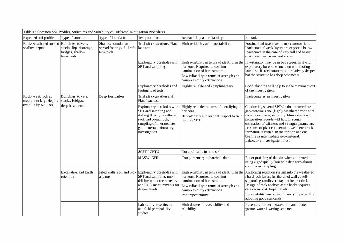
Table 1 : Common Soil Profiles, Structures and Suitability of Different Investigation Procedures
Expected soil profile Type of structure Type of foundation Test procedures Repeatability and reliability Remarks
Rock/ weathered rock at
shallow depths
Buildings, towers,
stacks, liquid storage,
bridges, shallow
basements
Shallow foundation –
spread footings, full raft,
tank pads
Trial pit excavations, Plate
load test
High reliability and repeatability. Footing load tests may be more appropriate.
Inadequate if weak layers are expected below.
Inadequate in the case of very tall and heavy
structures like towers and stacks
Exploratory boreholes with
SPT and sampling
High reliability in terms of identifying the
horizons. Required to confirm
continuation of hard stratum.
Low reliability in terms of strength and
compressibility estimations
Investigation may be in two stages, first with
exploratory boreholes and then with footing
load tests if rock stratum is at relatively deeper
but the structure has deep basements
Exploratory boreholes and
footing load tests
Highly reliable and complimentary Good planning will help to make maximum out
of the investigation.
Rock/ weak rock at
medium to large depths
overlain by weak soil
Buildings, towers,
stacks, bridges,
deep basements
Deep foundation Trial pit excavation and
Plate load test
Inadequate as an investigation
Exploratory boreholes with
SPT and sampling and
drilling through weathered
rock and sound rock,
sampling of intermediate
geo-material, laboratory
investigation
Highly reliable in terms of identifying the
horizons.
Repeatability is poor with respect to field
test like SPT
Conducting several SPTs in the intermediate
geo-material zone (highly weathered zone with
no core recovery) recording blow counts with
penetration records will help in rough
estimation of stiffness and strength parameters.
Presence of plastic material in weathered rock
formation is critical in the friction and end
bearing in intermediate geo-material.
Laboratory investigation must.
SCPT / CPTU Not applicable in hard soil
MASW, GPR Complimentary to borehole data Better profiling of the site when calibrated
using a god quality borehole data with almost
continuous sampling.
Excavation and Earth
retention
Piled walls, soil and rock
anchors
Exploratory boreholes with
SPT and sampling, rock
drilling with core recovery
and RQD measurements for
deeper levels
High reliability in terms of identifying the
horizons. Required to confirm
continuation of hard stratum.
Low reliability in terms of strength and
compressibility estimations.
Poor repeatability
Anchoring retention system into the weathered
/ hard rock layers for the piled wall as self-
supporting cantilever may not be practical.
Design of rock anchors as tie backs requires
data on rock at deeper levels.
Repeatability can be significantly improved by
adopting good standards
Laboratory investigation
and field permeability
studies
High degree of repeatability and
reliability
Necessary for deep excavation and related
ground water lowering schemes
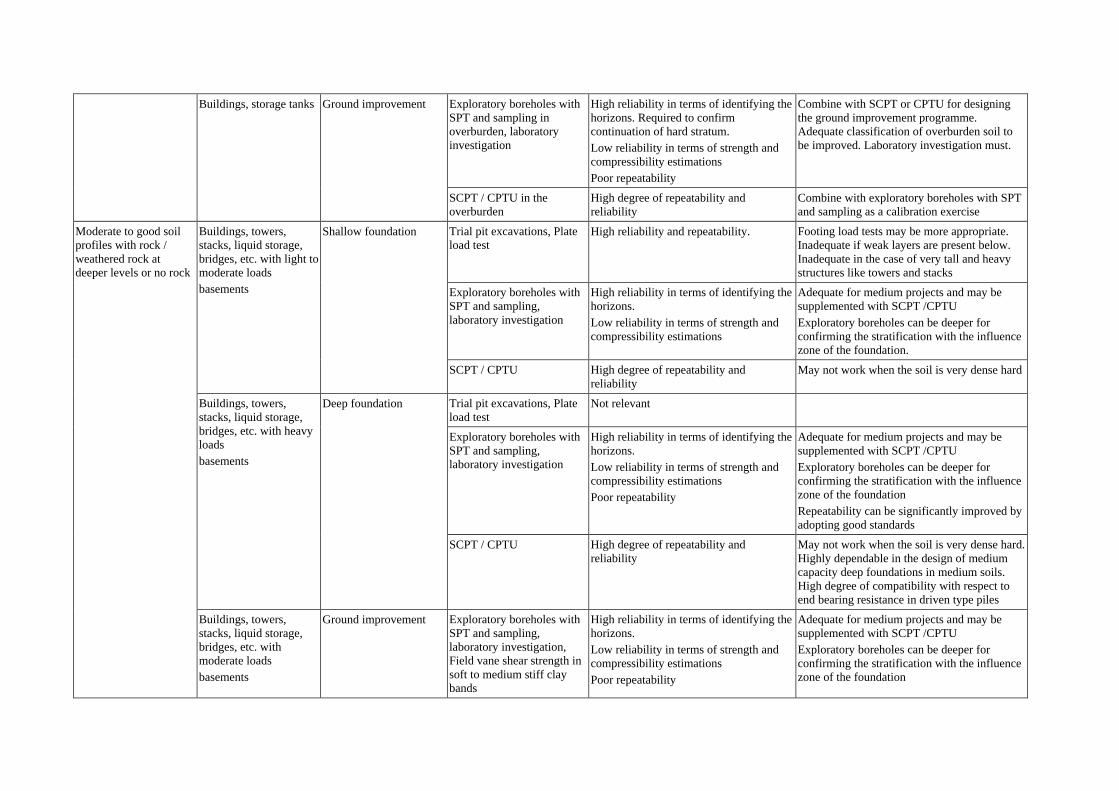
Buildings, storage tanks Ground improvement Exploratory boreholes with
SPT and sampling in
overburden, laboratory
investigation
High reliability in terms of identifying the
horizons. Required to confirm
continuation of hard stratum.
Low reliability in terms of strength and
compressibility estimations
Poor repeatability
Combine with SCPT or CPTU for designing
the ground improvement programme.
Adequate classification of overburden soil to
be improved. Laboratory investigation must.
SCPT / CPTU in the
overburden
High degree of repeatability and
reliability
Combine with exploratory boreholes with SPT
and sampling as a calibration exercise
Moderate to good soil
profiles with rock /
weathered rock at
deeper levels or no rock
Buildings, towers,
stacks, liquid storage,
bridges, etc. with light to
moderate loads
basements
Shallow foundation Trial pit excavations, Plate
load test
High reliability and repeatability. Footing load tests may be more appropriate.
Inadequate if weak layers are present below.
Inadequate in the case of very tall and heavy
structures like towers and stacks
Exploratory boreholes with
SPT and sampling,
laboratory investigation
High reliability in terms of identifying the
horizons.
Low reliability in terms of strength and
compressibility estimations
Adequate for medium projects and may be
supplemented with SCPT /CPTU
Exploratory boreholes can be deeper for
confirming the stratification with the influence
zone of the foundation.
SCPT / CPTU High degree of repeatability and
reliability
May not work when the soil is very dense hard
Buildings, towers,
stacks, liquid storage,
bridges, etc. with heavy
loads
basements
Deep foundation Trial pit excavations, Plate
load test
Not relevant
Exploratory boreholes with
SPT and sampling,
laboratory investigation
High reliability in terms of identifying the
horizons.
Low reliability in terms of strength and
compressibility estimations
Poor repeatability
Adequate for medium projects and may be
supplemented with SCPT /CPTU
Exploratory boreholes can be deeper for
confirming the stratification with the influence
zone of the foundation
Repeatability can be significantly improved by
adopting good standards
SCPT / CPTU High degree of repeatability and
reliability
May not work when the soil is very dense hard.
Highly dependable in the design of medium
capacity deep foundations in medium soils.
High degree of compatibility with respect to
end bearing resistance in driven type piles
Buildings, towers,
stacks, liquid storage,
bridges, etc. with
moderate loads
basements
Ground improvement Exploratory boreholes with
SPT and sampling,
laboratory investigation,
Field vane shear strength in
soft to medium stiff clay
bands
High reliability in terms of identifying the
horizons.
Low reliability in terms of strength and
compressibility estimations
Poor repeatability
Adequate for medium projects and may be
supplemented with SCPT /CPTU
Exploratory boreholes can be deeper for
confirming the stratification with the influence
zone of the foundation
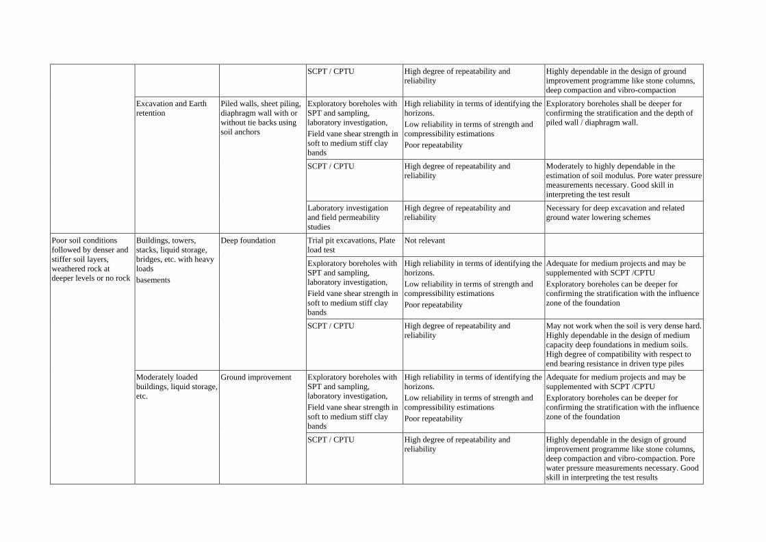
SCPT / CPTU High degree of repeatability and
reliability
Highly dependable in the design of ground
improvement programme like stone columns,
deep compaction and vibro-compaction
Excavation and Earth
retention
Piled walls, sheet piling,
diaphragm wall with or
without tie backs using
soil anchors
Exploratory boreholes with
SPT and sampling,
laboratory investigation,
Field vane shear strength in
soft to medium stiff clay
bands
High reliability in terms of identifying the
horizons.
Low reliability in terms of strength and
compressibility estimations
Poor repeatability
Exploratory boreholes shall be deeper for
confirming the stratification and the depth of
piled wall / diaphragm wall.
SCPT / CPTU High degree of repeatability and
reliability
Moderately to highly dependable in the
estimation of soil modulus. Pore water pressure
measurements necessary. Good skill in
interpreting the test result
Laboratory investigation
and field permeability
studies
High degree of repeatability and
reliability
Necessary for deep excavation and related
ground water lowering schemes
Poor soil conditions
followed by denser and
stiffer soil layers,
weathered rock at
deeper levels or no rock
Buildings, towers,
stacks, liquid storage,
bridges, etc. with heavy
loads
basements
Deep foundation Trial pit excavations, Plate
load test
Not relevant
Exploratory boreholes with
SPT and sampling,
laboratory investigation,
Field vane shear strength in
soft to medium stiff clay
bands
High reliability in terms of identifying the
horizons.
Low reliability in terms of strength and
compressibility estimations
Poor repeatability
Adequate for medium projects and may be
supplemented with SCPT /CPTU
Exploratory boreholes can be deeper for
confirming the stratification with the influence
zone of the foundation
SCPT / CPTU High degree of repeatability and
reliability
May not work when the soil is very dense hard.
Highly dependable in the design of medium
capacity deep foundations in medium soils.
High degree of compatibility with respect to
end bearing resistance in driven type piles
Moderately loaded
buildings, liquid storage,
etc.
Ground improvement Exploratory boreholes with
SPT and sampling,
laboratory investigation,
Field vane shear strength in
soft to medium stiff clay
bands
High reliability in terms of identifying the
horizons.
Low reliability in terms of strength and
compressibility estimations
Poor repeatability
Adequate for medium projects and may be
supplemented with SCPT /CPTU
Exploratory boreholes can be deeper for
confirming the stratification with the influence
zone of the foundation
SCPT / CPTU High degree of repeatability and
reliability
Highly dependable in the design of ground
improvement programme like stone columns,
deep compaction and vibro-compaction. Pore
water pressure measurements necessary. Good
skill in interpreting the test results

Excavation and Earth
retention
Piled walls, sheet piling,
diaphragm wall with or
without tie backs using
soil anchors
Exploratory boreholes with
SPT and sampling,
laboratory investigation,
Field vane shear strength in
soft to medium stiff clay
bands
High reliability in terms of identifying the
horizons.
Low reliability in terms of strength and
compressibility estimations
Poor repeatability
Exploratory boreholes shall be deeper for
confirming the stratification and the depth of
piled wall / diaphragm wall.
SCPT / CPTU High degree of repeatability and
reliability
Moderately to highly dependable in the
estimation of soil modulus
Laboratory investigation
and field permeability
studies
High degree of repeatability and
reliability
Necessary for deep excavation and related
ground water lowering schemes
All types of soil Site selection Trial pit excavations High reliability and repeatability. Good for weathered rock at shallow depths
Exploratory boreholes with
SPT and sampling
High reliability in terms of identifying the
horizons.
Low reliability in terms of strength and
compressibility estimations
Poor repeatability
Limited number of exploratory boreholes can
be easily executed
All types of soil Borrow earth studies Trial pit excavations,
sampling, laboratory
investigation
High reliability and repeatability. More numbers of excavations for varying soil
conditions.
Liquefiable soils Liquefaction studies Ground improvement for
mitigation
Exploratory boreholes with
SPT and sampling
High reliability in terms of identifying the
horizons.
Low reliability in terms of strength and
compressibility estimations
Poor repeatability
SPT and sampling at least possible interval to
represent continuous sampling
CPTU Moderate reliability in terms of
identifying the horizons.
High reliability in terms of strength and
compressibility estimations
High repeatability
Pore water pressure measurements necessary.
Good skill in interpreting the test results
Cross hole and wave
velocity measurements
Moderate reliability in terms of
identifying the horizons.
High reliability in terms of strength and
compressibility estimations
High repeatability
Common remark for exploratory borehole, SPT and sampling-Continuous sampling procedure improves the quality of investigation and repeatability. Hollow stem auguring is advantageous. SPT
with self-trip mechanism improves the repeatability. Repeatability of in-situ tests can be significantly improved by adopting good standards