Embed Size (px)
Citation preview
IHC Vremac CylindersCylinder Catalogue 210 bar / 320 bar
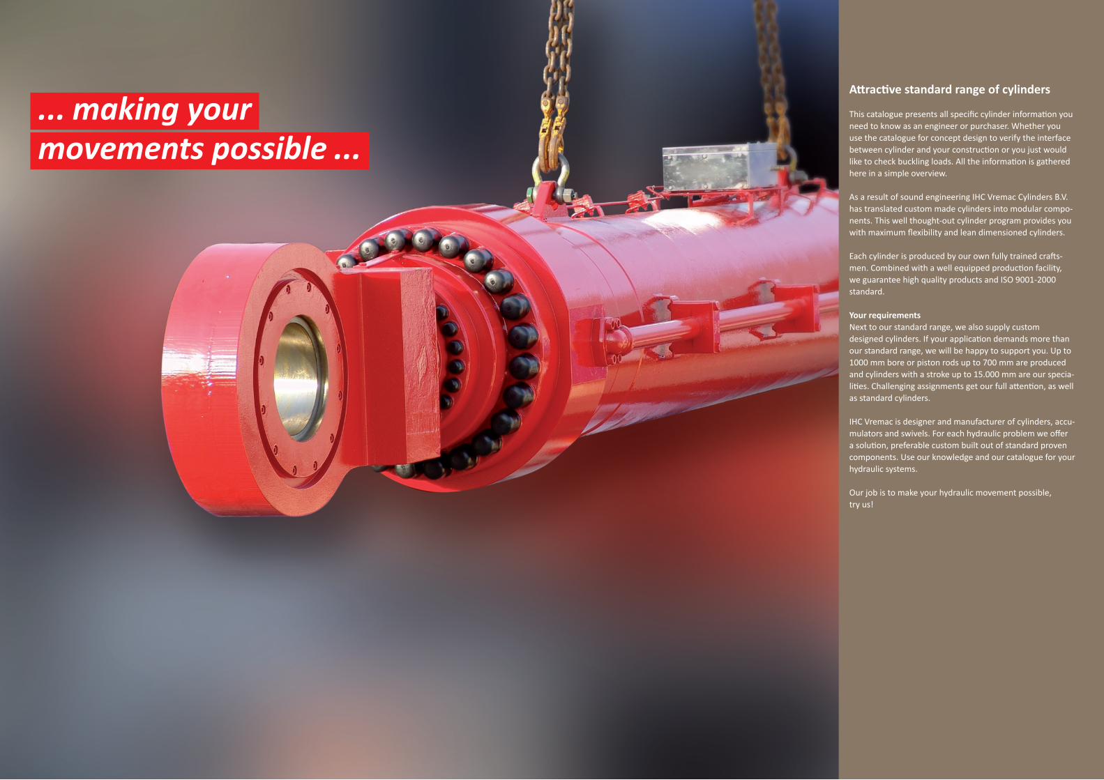
Attractive standard range of cylinders
This catalogue presents all specific cylinder information you need to know as an engineer or purchaser. Whether you use the catalogue for concept design to verify the interface between cylinder and your construction or you just would like to check buckling loads. All the information is gathered here in a simple overview.
As a result of sound engineering IHC Vremac Cylinders B.V. has translated custom made cylinders into modular compo-nents. This well thought-out cylinder program provides you with maximum flexibility and lean dimensioned cylinders.
Each cylinder is produced by our own fully trained crafts-men. Combined with a well equipped production facility, we guarantee high quality products and ISO 9001-2000 standard.
Your requirementsNext to our standard range, we also supply customdesigned cylinders. If your application demands more than our standard range, we will be happy to support you. Up to 1000 mm bore or piston rods up to 700 mm are produced and cylinders with a stroke up to 15.000 mm are our specia-lities. Challenging assignments get our full attention, as well as standard cylinders.
IHC Vremac is designer and manufacturer of cylinders, accu-mulators and swivels. For each hydraulic problem we offer a solution, preferable custom built out of standard proven components. Use our knowledge and our catalogue for your hydraulic systems.
Our job is to make your hydraulic movement possible,try us!
... making your movements possible ...
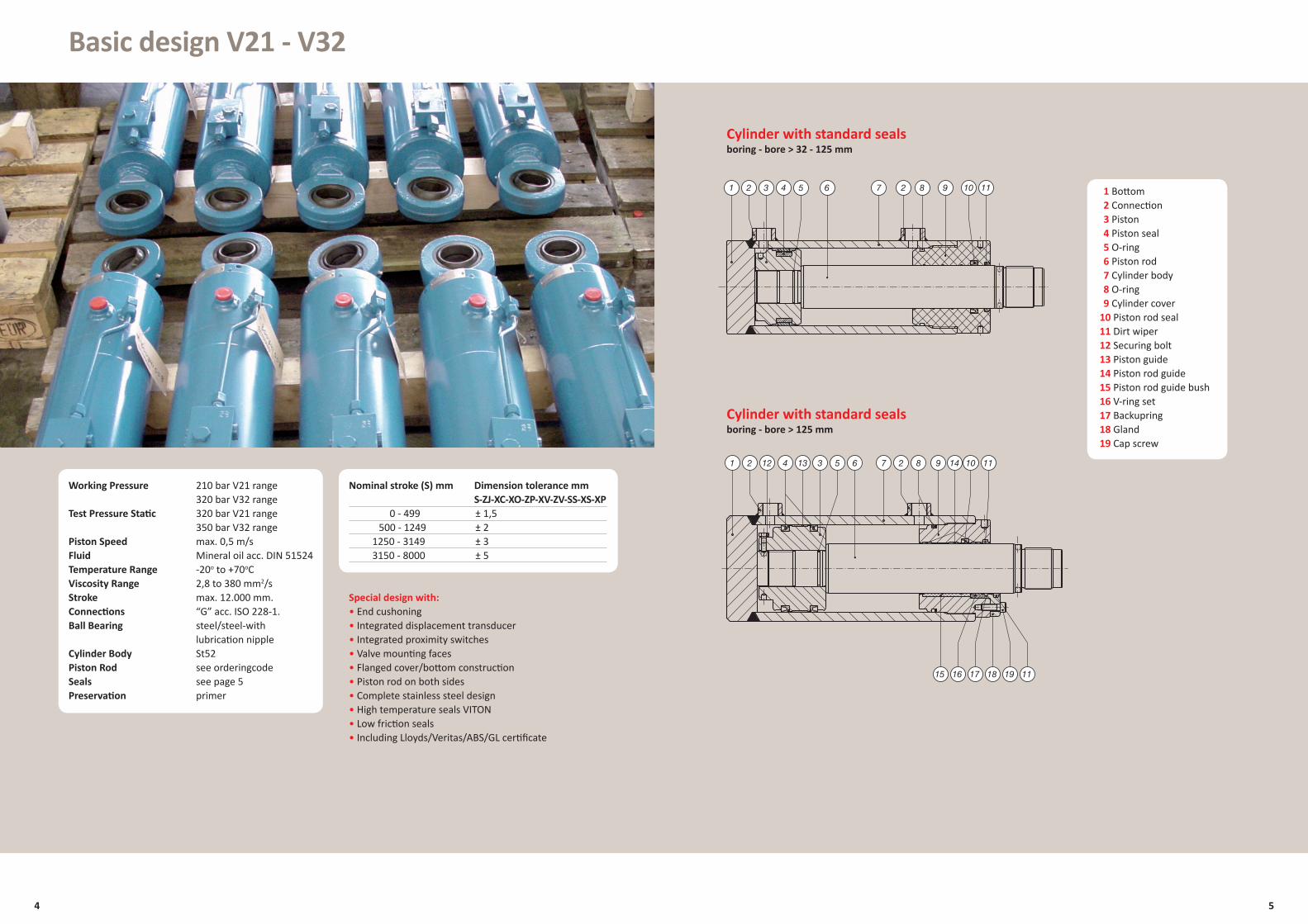
Basic design V21 - V32
Special design with:• End cushoning• Integrated displacement transducer• Integrated proximity switches• Valve mounting faces• Flanged cover/bottom construction• Piston rod on both sides• Complete stainless steel design• High temperature seals VITON• Low friction seals• Including Lloyds/Veritas/ABS/GL certificate
Nominal stroke (S) mm Dimension tolerance mm S-ZJ-XC-XO-ZP-XV-ZV-SS-XS-XP 0 - 499 ± 1,5 500 - 1249 ± 2 1250 - 3149 ± 3 3150 - 8000 ± 5
Cylinder with standard sealsboring - bore > 32 - 125 mm
Cylinder with standard sealsboring - bore > 125 mm
4
1 2 23 4 5 6 7 8 9 10 11
1 22 34 5 6 7 8 9 10 11
1116
12 13 14
15 17 18 19
5
Working Pressure 210 bar V21 range 320 bar V32 rangeTest Pressure Static 320 bar V21 range 350 bar V32 rangePiston Speed max. 0,5 m/s Fluid Mineral oil acc. DIN 51524Temperature Range -20o to +70oCViscosity Range 2,8 to 380 mm2/sStroke max. 12.000 mm. Connections “G” acc. ISO 228-1.Ball Bearing steel/steel-with lubrication nippleCylinder Body St52Piston Rod see orderingcodeSeals see page 5Preservation primer
10 Piston rod seal11 Dirt wiper12 Securing bolt13 Piston guide14 Piston rod guide15 Piston rod guide bush16 V-ring set17 Backupring18 Gland19 Cap screw
1 Bottom2 Connection3 Piston4 Piston seal5 O-ring6 Piston rod7 Cylinder body8 O-ring9 Cylinder cover
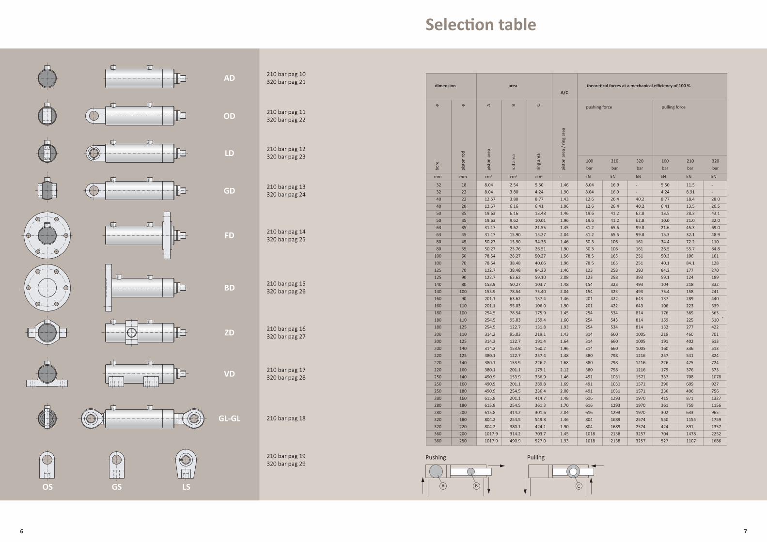
Selection table
dimension area theoretical forces at a mechanical efficiency of 100 % A/C
pushing force pulling force
mm mm cm2 cm2 cm2 - kN kN kN kN kN kN
100bar
210bar
320bar
100bar
210bar
320barbo
re
ø
pist
on ro
d ø
pist
on a
rea
A
rod
area
B
ring
area
C
pist
on a
rea
/ rin
g ar
ea
AD
OD
LD
GD
FD
BD
ZD
VD
GL-GL
OS GS LS
210 bar pag 10320 bar pag 21
210 bar pag 11320 bar pag 22
210 bar pag 12320 bar pag 23
210 bar pag 13320 bar pag 24
210 bar pag 14320 bar pag 25
210 bar pag 15320 bar pag 26
210 bar pag 16320 bar pag 27
210 bar pag 17320 bar pag 28
210 bar pag 18
210 bar pag 19320 bar pag 29
6 7
Pushing Pulling
32 18 8.04 2.54 5.50 1.46 8.04 16.9 - 5.50 11.5 - 32 22 8.04 3.80 4.24 1.90 8.04 16.9 - 4.24 8.91 - 40 22 12.57 3.80 8.77 1.43 12.6 26.4 40.2 8.77 18.4 28.0 40 28 12.57 6.16 6.41 1.96 12.6 26.4 40.2 6.41 13.5 20.5 50 35 19.63 6.16 13.48 1.46 19.6 41.2 62.8 13.5 28.3 43.1 50 35 19.63 9.62 10.01 1.96 19.6 41.2 62.8 10.0 21.0 32.0 63 35 31.17 9.62 21.55 1.45 31.2 65.5 99.8 21.6 45.3 69.0 63 45 31.17 15.90 15.27 2.04 31.2 65.5 99.8 15.3 32.1 48.9 80 45 50.27 15.90 34.36 1.46 50.3 106 161 34.4 72.2 110 80 55 50.27 23.76 26.51 1.90 50.3 106 161 26.5 55.7 84.8 100 60 78.54 28.27 50.27 1.56 78.5 165 251 50.3 106 161 100 70 78.54 38.48 40.06 1.96 78.5 165 251 40.1 84.1 128 125 70 122.7 38.48 84.23 1.46 123 258 393 84.2 177 270 125 90 122.7 63.62 59.10 2.08 123 258 393 59.1 124 189 140 80 153.9 50.27 103.7 1.48 154 323 493 104 218 332 140 100 153.9 78.54 75.40 2.04 154 323 493 75.4 158 241 160 90 201.1 63.62 137.4 1.46 201 422 643 137 289 440 160 110 201.1 95.03 106.0 1.90 201 422 643 106 223 339 180 100 254.5 78.54 175.9 1.45 254 534 814 176 369 563
.180 110 254.5 95.03 159.4 1.60 254 543 814 159 225 510 180 125 254.5 122.7 131.8 1.93 254 534 814 132 277 422 200 110 314.2 95.03 219.1 1.43 314 660 1005 219 460 701 200 125 314.2 122.7 191.4 1.64 314 660 1005 191 402 613 200 140 314.2 153.9 160.2 1.96 314 660 1005 160 336 513 220 125 380.1 122.7 257.4 1.48 380 798 1216 257 541 824 220 140 380.1 153.9 226.2 1.68 380 798 1216 226 475 724 220 160 380.1 201.1 179.1 2.12 380 798 1216 179 376 573 250 140 490.9 153.9 336.9 1.46 491 1031 1571 337 708 1078 250 160 490.9 201.1 289.8 1.69 491 1031 1571 290 609 927 250 180 490.9 254.5 236.4 2.08 491 1031 1571 236 496 756 280 160 615.8 201.1 414.7 1.48 616 1293 1970 415 871 1327 280 180 615.8 254.5 361.3 1.70 616 1293 1970 361 759 1156 280 200 615.8 314.2 301.6 2.04 616 1293 1970 302 633 965 320 180 804.2 254.5 549.8 1.46 804 1689 2574 550 1155 1759 320 220 804.2 380.1 424.1 1.90 804 1689 2574 424 891 1357 360 200 1017.9 314.2 703.7 1.45 1018 2138 3257 704 1478 2252 360 250 1017.9 490.9 527.0 1.93 1018 2138 3257 527 1107 1686
A B C
7 7
7
Lk=2L
7
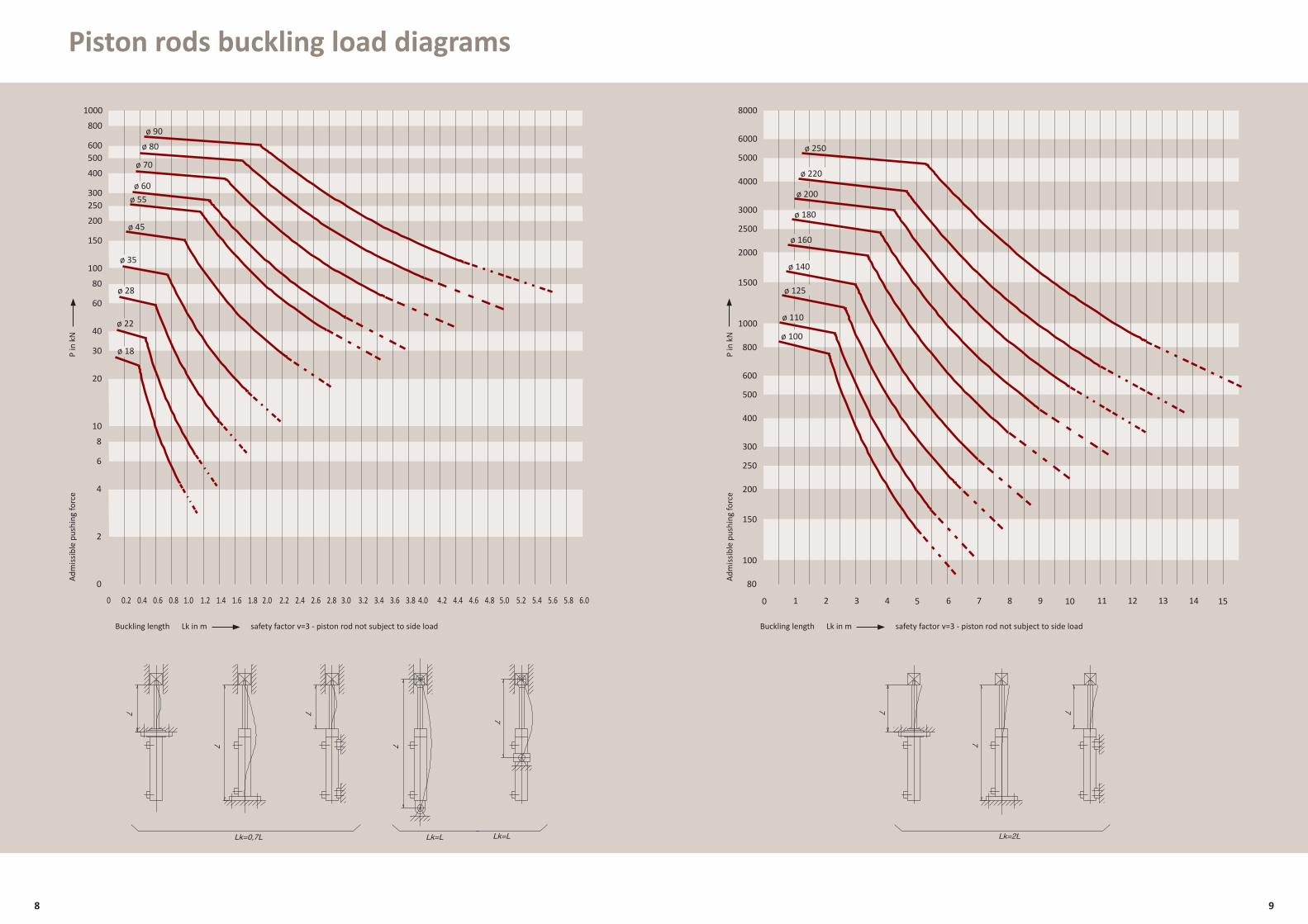
Lk=L
7 7
77
Lk=0,7L Lk=L
Adm
issib
le p
ushi
ng fo
rce
P in
kN
Buckling length Lk in m safety factor v=3 - piston rod not subject to side load
2
4
6
8
10
20
30
40
60
80
100
0 1.0 2.0 3.0 4.0 5.0 6.00.2 0.4 0.6 0.8 1.2 1.4 1.6 1.8 2.2 2.4 2.6 2.8 3.2 3.4 3.6 3.8 4.2 4.4 4.6 4.8 5.2 5.4 5.6 5.8
150
200
250300
400
500600
800
1000
0
ø 18
ø 22
ø 35
ø 45
ø 55ø 60
ø 28
ø 70
ø 80
ø 90
80
100
1000
150
200
250
300
400
500
600
800
1500
2000
2500
3000
4000
5000
6000
8000
5 10 150 1 2 3 4 6 7 8 9 11 12 13 14
ø 110
ø 125
ø 140
ø 100
ø 160
ø 180
ø 200
ø 220
ø 250
P in
kN
Adm
issib
le p
ushi
ng fo
rce
Buckling length Lk in m safety factor v=3 - piston rod not subject to side load
8 9
7 7
7
Lk=2L
7
Lk=L
Piston rods buckling load diagrams
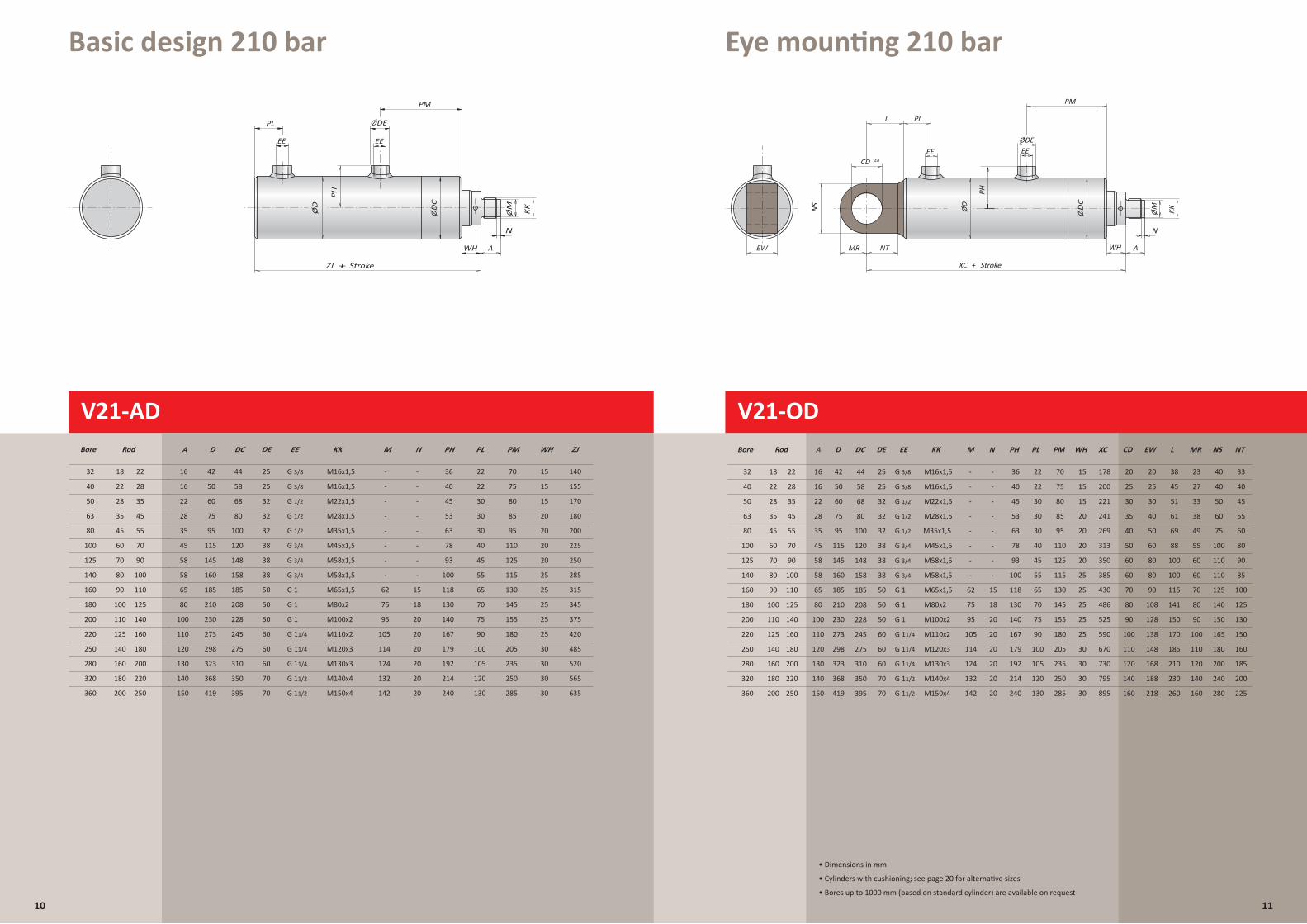
Basic design 210 bar Eye mounting 210 bar
V21-AD
10
ZJ + Stroke
WH
PL ØDE
ØD
PH
ØM KK
PM
N
A
EE EE
ZJ + Stroke
WH
PL ØDE
ØD
PH
ØM KK
PM
N
A
EE EE
40
Bore Rod
22 28
50 28 35
63
80
100
125
140
160
180
200
220
250
280
320
360
A D DE EE KK M N PH PL PM WH ZJ
16
22
50
60
25
32
M16x1,5
M22x1,5
- -
- -
40
45
22
30
75
80
15
15
155
170
V21-AD
35
45
60
70
80
90
100
110
125
140
160
180
200
45
55
70
90
100
110
125
140
160
180
200
220
250
28
35
45
58
58
65
80
100
110
120
130
140
150
75
95
115
145
160
185
210
230
273
298
323
368
419
32
32
38
38
38
50
50
50
60
60
60
70
70
M28x1,5
M35x1,5
M45x1,5
M58x1,5
M58x1,5
M65x1,5
M80x2
M100x2
M110x2
M120x3
M130x3
M140x4
M150x4
53
63
78
93
100
118
130
140
167
179
192
214
240
30
30
40
45
55
65
70
75
90
100
105
120
130
85
95
110
125
115
130
145
155
180
205
235
250
285
20
20
20
20
25
25
25
25
25
30
30
30
30
180
200
225
250
285
315
345
375
420
485
520
565
635
-
- -
-
- -
-
-
62
75
95
105
114
124
132
142
-
15
-
18
20
20
20
20
20
20
Basic design
32 18 22 16 42 25
G 1/2
G 1
G 1
G 1
G 11/4
G 11/4
G 11/4
G 11/2
G 11/2
G 1/2
G 3/8
G 1/2
G 3/4
G 3/4
G 3/4
G 3/8 M16x1,5 36-- 22 70 15 140
210 bar
80
185
208
228
245
275
310
350
395
68
58
100
120
148
158
44
DC
XC + Stroke
EW
L
NTMR
CD E8
WH
PL
ØDE
PM
KKØMØD
PH
NS
N
A
EE EE
XC + Stroke
EW
L
NTMR
CD E8
WH
PL
ØDE
PM
KKØMØD
PH
NS
N
A
EE EE
40
Bore Rod
22 28
50 28 35
63
80
100
125
140
160
180
200
220
250
280
320
360
A D EE KK M N PH PL PM WH XC
16
22
50
60
M16x1,5
M22x1,5
- -
- -
40
45
22
30
75
80
15
15
200
221
V21-OD
62
35
45
60
70
80
90
100
110
125
140
160
180
200
45
55
70
90
100
110
125
140
160
180
200
220
250
28
35
45
58
58
65
80
100
110
120
130
140
150
75
95
115
145
160
185
210
230
273
298
323
368
419
M28x1,5
M35x1,5
M45x1,5
M58x1,5
M58x1,5
M65x1,5
M80x2
M100x2
M110x2
M120x3
M130x3
M140x4
M150x4
53
63
78
93
100
118
130
140
167
179
192
214
240
30
30
40
45
55
65
70
75
90
100
105
120
130
85
95
110
125
115
130
145
155
180
205
235
250
285
20
20
20
20
25
25
25
25
25
30
30
30
30
241
269
313
350
385
430
486
525
590
670
730
795
895
-
- -
-
- -
-
-
75
95
105
114
124
132
142
-
15
-
18
20
20
20
20
20
20
Eye mounting
32 18 22 16 42
DE
25
32
32
32
38
38
38
50
50
50
60
60
60
70
70
25
G 1/2
G 1
G 1
G 1
G 11/4
G 11/4
G 11/4
G 11/2
G 11/2
G 1/2
G 3/8
G 1/2
G 3/4
G 3/4
G 3/4
G 3/8 M16x1,5 36-- 22 70 15 178
CD
25
30
35
40
50
60
60
70
80
90
100
110
120
140
160
20 20
25
30
40
50
60
80
80
90
108
128
138
148
168
188
218
EW L
45
51
61
69
88
100
100
115
141
150
170
185
210
230
260
38
210 bar
NS
40
50
60
75
100
110
110
125
140
150
165
180
200
240
280
40
NT
40
45
55
60
80
90
85
100
125
130
150
160
185
200
225
33
MR
27
33
38
49
55
60
60
70
80
90
100
110
120
140
160
23
80
185
208
228
245
275
310
350
395
68
58
100
120
148
158
44
DC
V21-OD
• Dimensions in mm
• Cylinders with cushioning; see page 20 for alternative sizes
• Bores up to 1000 mm (based on standard cylinder) are available on request
11
ØD
C
ØD
C
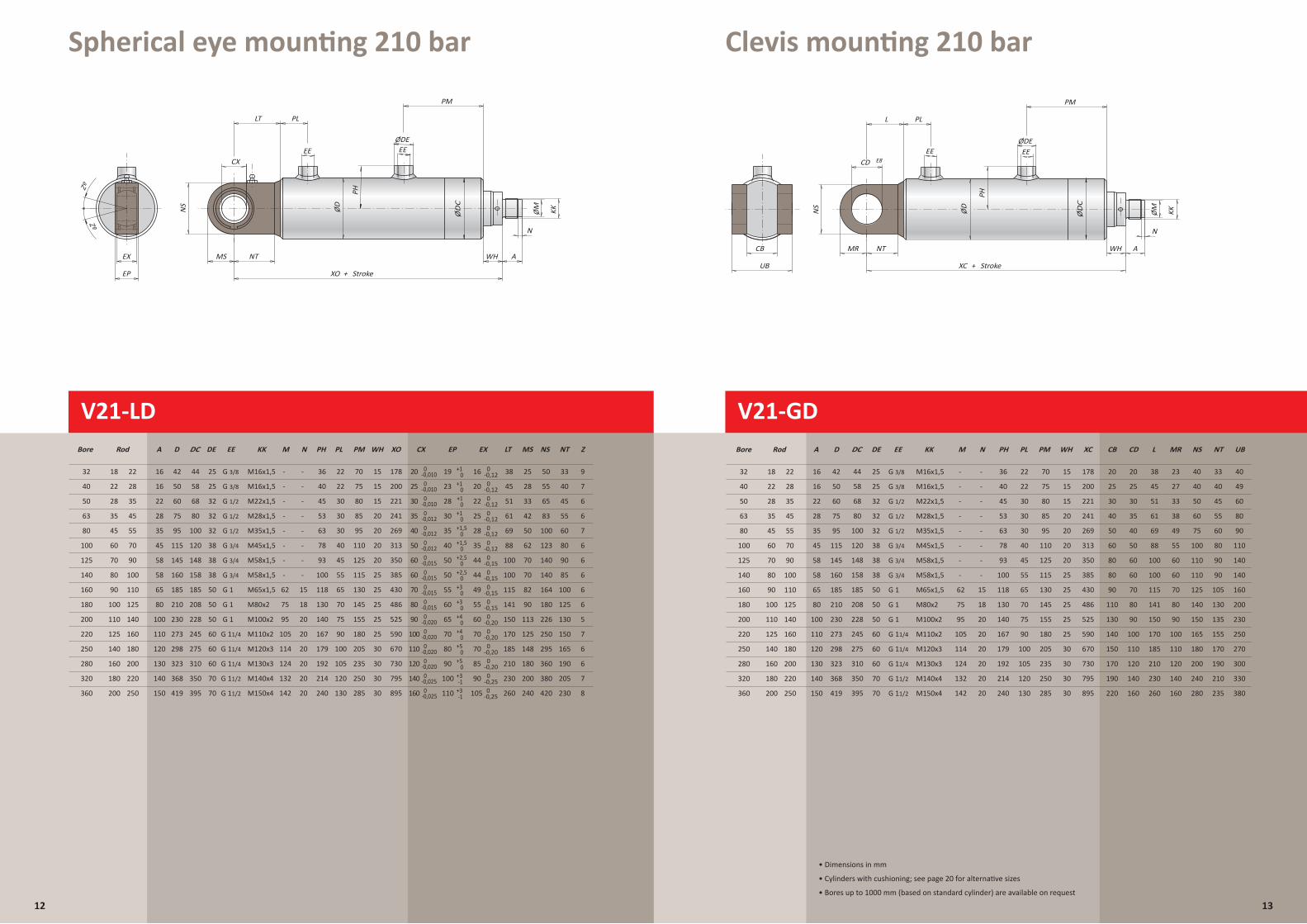
Spherical eye mounting 210 bar Clevis mounting 210 bar
12
LT
XO + Stroke
CX
MS NT
EP
EX WH A
PL
ØDE
PM
N
EE EE
KKØMØD
PH
NS
Zº
Zº
XC + StrokeUB
CB
L
NTMR
CD E8
WH
PL
ØDE
ØM KK
PH
ØD
NS
PM
N
A
EE EELT
XO + Stroke
CX
MS NT
EP
EX WH A
PL
ØDE
PM
N
EE EE
KKØMØD
PH
NS
+1
+1
+1
40
Bore Rod
22 28
50 28 35
63
80
100
125
140
160
180
200
220
250
280
320
360
EE KK M N PH PL PM WH XO
M16x1,5
M22x1,5
- -
- -
40
45
22
30
75
80
15
15
200
221
V21-LD Gelenkoog aan bodem
35
45
60
70
80
90
100
110
125
140
160
180
200
45
55
70
90
100
110
125
140
160
180
200
220
250
M28x1,5
M35x1,5
M45x1,5
M58x1,5
M58x1,5
M65x1,5
M80x2
M100x2
M110x2
M120x3
M130x3
M140x4
M150x4
53
63
78
93
100
118
130
140
167
179
192
214
240
30
30
40
45
55
65
70
75
90
100
105
120
130
85
95
110
125
115
130
145
155
180
205
235
250
285
20
20
20
20
25
25
25
25
25
30
30
30
30
241
269
313
350
385
430
486
525
590
670
730
795
895
-
- -
-
- -
-
-
75
95
105
114
124
132
142
-
15
-
18
20
20
20
20
20
20
Spherical eye mounting
32 18 22
A
16
22
28
35
45
58
58
65
80
100
110
120
130
140
150
16
D
50
60
75
95
115
145
160
185
210
230
273
298
323
368
419
42
DE
25
32
32
32
38
38
38
50
50
50
60
60
60
70
70
25
G 1/2
G 1
G 1
G 1
G 11/4
G 11/4
G 11/4
G 11/2
G 11/2
G 1/2
G 3/8
G 1/2
G 3/4
G 3/4
G 3/4
G 3/8 M16x1,5 36-- 22 70 15 178
+1
+1,5
CX
25
30
35
40
50
60
60
70
80
90
100
110
120
140
160
20 16
20
22
25
28
35
44
44
49
55
60
70
70
85
90
105
EX LT
45
51
61
69
88
100
100
115
141
150
170
185
210
230
260
38
NS
55
65
83
100
123
140
140
164
180
226
250
295
360
380
420
50
NT
40
45
55
60
80
90
85
100
125
130
150
165
190
205
230
3319
23
28
30
35
40
50
50
55
60
65
70
80
90
MS
28
33
42
50
62
70
70
82
90
113
125
148
180
200
240
100
25
110
EP
+1,5
+2,5
+2,5
+3
+3
+4
+4
+5
+5
62
+3
+3
0
0
0
0
0
0
0
0
0
0
0
0
0
0
-1
-1
Gelenkauge am Zylinderboden
210 bar
Zº
Z
7
6
6
7
6
Zº
6
6
6
6
5
7
6
6
7
8
9
R
0
0
0
0
0
0
0
0
0
0
0
0
0
0
0
0-0,010
-0,025
-0,025
-0,020
-0,020
-0,020
-0,020
-0,015
-0,015
-0,015
-0,015
-0,012
-0,012
-0,012
-0,010
-0,010
0
0
0
0
0
0
0
0
0
0
0
0
0
0
0
0
-0,12
-0,12
-0,12
-0,12
-0,12
-0,12
-0,15
-0,15
-0,15
-0,15
-0,20
-0,20
-0,20
-0,20
-0,25
-0,25
80
185
208
228
245
275
310
350
395
68
58
100
120
148
158
44
DC
V21-LD V21-GD
XC + StrokeUB
CB
L
NTMR
CD E8
WH
PL
ØDE
ØM KK
PH
ØD
NS
PM
N
A
EE EE
40
Bore Rod
22 28
50 28 35
63
80
100
125
140
160
180
200
220
250
280
320
360
KK M N PH PL PM WH XC
M16x1,5
M22x1,5
- -
- -
40
45
22
30
75
80
15
15
200
221
V21-GD
35
45
60
70
80
90
100
110
125
140
160
180
200
45
55
70
90
100
110
125
140
160
180
200
220
250
M28x1,5
M35x1,5
M45x1,5
M58x1,5
M58x1,5
M65x1,5
M80x2
M100x2
M110x2
M120x3
M130x3
M140x4
M150x4
53
63
78
93
100
118
130
140
167
179
192
214
240
30
30
40
45
55
65
70
75
90
100
105
120
130
85
95
110
125
115
130
145
155
180
205
235
250
285
20
20
20
20
25
25
25
25
25
30
30
30
30
241
269
313
350
385
430
486
525
590
670
730
795
895
-
- -
-
- -
-
-
75
95
105
114
124
132
142
-
15
-
18
20
20
20
20
20
20
Clevis mounting
32 18 22
A
16
22
28
35
45
58
58
65
80
100
110
120
130
140
150
16
D
50
60
75
95
115
145
160
185
210
230
273
298
323
368
419
42
DE
25
32
32
32
38
38
38
50
50
50
60
60
60
70
70
25
EE
G 1/2
G 1
G 1
G 1
G 11/4
G 11/4
G 11/4
G 11/2
G 11/2
G 1/2
G 3/8
G 1/2
G 3/4
G 3/4
G 3/4
G 3/8 M16x1,5 36-- 22 70 15 178
CD
25
30
35
40
50
60
60
70
80
90
100
110
120
140
160
2020
25
30
40
50
60
80
80
90
110
130
140
150
170
190
220
CB L
45
51
61
69
88
100
100
115
141
150
170
185
210
230
260
38
MR
27
33
38
49
55
60
60
NS
40
50
60
75
100
110
110
125
140
150
165
180
200
240
280
70
40
80
90
100
110
120
140
160
23
62
210 bar
NT
40
45
55
60
80
90
90
105
130
135
155
170
190
210
235
33
UB
49
60
80
90
110
140
140
160
200
230
250
270
300
330
380
40
R
80
185
208
228
245
275
310
350
395
68
58
100
120
148
158
44
DC
13
• Dimensions in mm
• Cylinders with cushioning; see page 20 for alternative sizes
• Bores up to 1000 mm (based on standard cylinder) are available on request
ØD
C
ØD
C
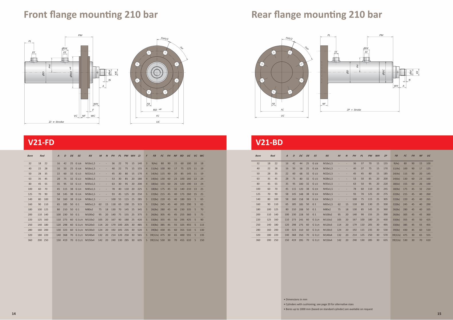
Front flange mounting 210 bar
V21-BD
Rear flange mounting 210 bar
14
ZP + Stroke
FHº
FHº/2
FB
UC
FC
PL
WH
KKØMØD
PH
N
A
ØDEEE
NF
PM
EE
210 bar
100
115
130
V21-BD
Bodemflens
155
175
215
220
FC
245
280
305
355
80
385
430
475
Rear flange mounting
530
11(4x) 17
14(4x) 20
14(6x) 23
18(6x)
Flansch am Zylinderboden
26
18(8x) 32
22(8x) 40
22(8x) 40
FB
22(8x) 40
26(8x) 40
26(8x) 45
33(8x) 50
9(4x)
NF
33(8x) 55
39(8x) 60
39(12x) 65
39(12x) 70
15
90
90
60
60
45
45
45
FH
45
45
45
45
90
45
45
30
30
125
145
160
190
210
260
265
290
335
360
425
UC
455
510
555
610
10032
Bore Rod
18 22
50 28 35
63
80
100
125
140
160
180
200
220
250
280
320
360
A EE KK M N PH PL PM ZP
16
22
M16x1,5
M22x1,5
- -
- -
36
45
37
45
70
80
155
185
35
45
60
70
80
90
100
110
125
140
160
180
200
45
55
70
90
100
110
125
140
160
180
200
220
250
28
35
45
58
58
65
80
100
110
120
130
140
150
M28x1,5
M35x1,5
M45x1,5
M58x1,5
M58x1,5
M65x1,5
M80x2
M100x2
M110x2
M120x3
M130x3
M140x4
M150x4
53
63
78
93
100
118
130
140
167
179
192
214
240
50
50
60
70
75
80
85
90
100
110
115
125
130
85
95
110
125
115
130
145
155
180
205
235
250
285
200
220
245
275
305
330
360
390
430
495
530
570
-
- -
-
- -
-
62
75
95
105
114
124
132
142
-
- -
18
15
20
20
20
20
20
20
WH
15
40 22 28 16
D
42
60
75
95
115
145
160
185
210
230
273
298
323
368
419
50
DE
25
32
32
32
38
38
38
50
50
50
60
60
60
70
70
25 M16x1,5 - - 40 37 75 17015
15
20
20
20
20
25
25
25
25
25
30
30
30
30
G 1/2
G 1
G 1
G 1
G 11/4
G 11/4
G 11/4
G 11/2
G 11/2
G 1/2
G 3/8
G 1/2
G 3/4
G 3/4
G 3/8
G 3/4
ZP + Stroke
FHº
FHº/2
FB
UC
FC
PL
WH
KKØMØD
PH
N
A
ØDEEE
NF
PM
EE
635
80
185
208
228
245
275
310
350
395
68
58
100
120
148
158
44
DC
ZJ + Stroke
FHº
FHº/2
FB
UC
NF FCVC
ØR
D
ØD
PH
ØM
e8
F
PL
KK
N
A
ØDEEE
WC
PM
RD e8
EE
WH
V21-FD
V21-FD Frontflens
Front flange mounting
210 bar
Flansch am Zylinderkopf
R
ZJ + Stroke
FHº
FHº/2
FB
UC
FC
RD e8
WH
WC
F
VC NF
ØRD
e8
PLØDE
PM
KKØMØD
PH
N
A
EE EE
Bore Rod A D DE EE KK M N PH PL PM WH ZJ FCF FB NF RD UC VC WCFH
40 22 28
50 28 35
63
80
100
125
140
160
180
200
220
250
280
320
360
10016
22
50
60
25
32
M16x1,5
M22x1,5
- -
- -
40
45
22
30 115
130
75
80
15
15
155
170
35
45
60
70
80
90
100
110
125
140
160
180
200
45
55
70
90
100
110
125
140
160
180
200
220
250
28
35
45
58
58
65
80
100
110
120
130
140
150
75
95
115
145
160
185
210
230
273
298
323
368
419
32
32
38
38
38
50
50
50
60
60
60
70
70
M28x1,5
M35x1,5
M45x1,5
M58x1,5
M58x1,5
M65x1,5
M80x2
M100x2
M110x2
M120x3
M130x3
M140x4
M150x4
53
63
78
93
100
118
130
140
167
179
192
214
240
30
30
40
45
55
65
70
75
90
100
105
120
130
85
95
110
125
115
130
145
155
180
155
175
215
220
245
280
305
355
80
385
430
475
205
235
250
285
20
20
20
20
25
25
25
25
25
30
30
30
30
180
200
225
250
285
315
345
375
420
485
520
565
635
-
- -
-
- -
-
-
62
75
95
105
114
124
132
142
-
15
-
18
20
20
20
20
20
20 530
4 11(4x) 17
4 14(4x) 20
4
32
14(6x) 23
4
18
18(6x)
322
26
5
16
18(8x) 32
5
42
22(8x) 40
5
25
22(8x) 40
5
G 1/2
G 1
G 1
G 1
G 11/4
G 11/4
G 11/4
G 11/2
G 11/2
G 1/2
G 3/8
G 1/2
G 3/4
G 3/4
G 3/4
G 3/8
22(8x) 40
5
M16x1,5
26(8x) 40
5
36
26(8x) 45
5
-
33(8x) 50
5
9(4x)-
33(8x) 55
5
22
39(8x) 60
5
70
39(12x) 65
5
15
39(12x) 70
15140
75
85
100
120
140
175
180
205
230
255
295
325
355
400
455
60
125
145
160
190
210
260
265
290
335
360
425
455
510
555
610
100
11
11
13
13
13
15
5
5
5
5
5
5
5
5
5
10
19
19
24
24
25
25
65
65
70
75
90
115
130
135
150
18
90
90
60
60
45
45
45
45
45
45
45
90
45
45
30
30
15
• Dimensions in mm
• Cylinders with cushioning; see page 20 for alternative sizes
• Bores up to 1000 mm (based on standard cylinder) are available on request
ØD
C
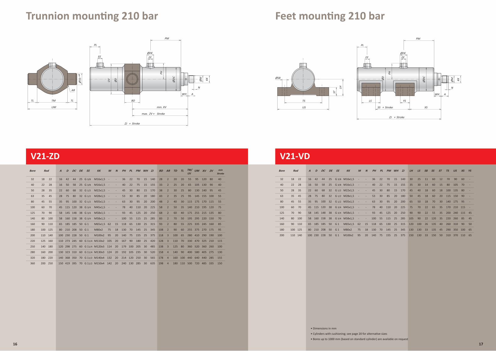
Trunnion mounting 210 bar Feet mounting 210 bar
16 17
SS + Stroke
ZJ + Stroke
ØSB
LS
XS
YS
US
TS
PL
N
A
ØDE
ØD
LH
ST
PH
KKØM
EE
WH
PM
EE
40
Bore Rod
22 28
50 28 35
63
80
100
125
140
160
180
200
60
35
45
50
65
75
90
105
120
130
DE KK M N PH PL PM WH ZJ
25
32
M16x1,5
M22x1,5
- -
- -
V21-VD
140
Voeten
40
45
22
30
75
80
15
15
210 bar
155
170
35
45
60
70
80
90
100
110 150
30
40
45
50
45
55
70
90
100
110
125
140
70
90
90
100
130
Fu·befestigung
130
14
18
18
18
22
22
22
26
33
32
32
38
38
38
50
TS US XS
50
50 33
60
60
60
70
70
65
55
120
135
135
150
15
18
20
30
35
35
35
40
45
50
80
100
M28x1,5
M35x1,5
M45x1,5
M58x1,5
90
115
140
170
200
M58x1,5
M65x1,5
M80x2
M100x2
220
260
290
310
105
53
63
135
150
175
210
240
78
93
100
118
130
260
310
350
370
70
Feet mounting
80
90
95
115
115
85
90
30
30
40
45
55
65
70
LS
25 11 60 12 -
100
110
-
-
-
-
-
45
45
50
65
65
LH
30
SB
75
SS
85
ST
95
110
125
115
130
145
YS
155
20
20
20
20
25
25
25
25
180
200
225
250
285
315
345
375
-
- -
-
- -
-
-
62
75
95
-
15
-
18
20
32 18 22
A
16
22
28
35
45
58
58
65
80
100
16
D
50
60
75
95
115
145
160
185
210
230
42 25
EE
G 1/2
G 1
G 1
G 1
G 1/2
G 3/8
G 1/2
G 3/4
G 3/4
G 3/4
G 3/8 M16x1,5 36-- 22 70 15 140
80
185
208
228
68
58
100
120
148
158
44
DC
ZJ + Stroke
max. ZV + Stroke
AR
min. XV
BD
UM
TL TLTM
ØTD UV
ØD
PH
ØM KK
e8
PL
N
A
ØDEEE
WH
PM
EE
SS + Stroke
ZJ + Stroke
ØSB
LS
XS
YS
US
TS
PL
N
A
ØDE
ØD
LH
ST
PH
KKØM
EE
WH
PM
EE
• Dimensions in mm
• Cylinders with cushioning; see page 20 for alternative sizes
• Bores up to 1000 mm (based on standard cylinder) are available on request
ZJ + Stroke
max. ZV + Stroke
AR
min. XV
BD
UM
TL TLTM
ØTD UV
ØD
PH
ØM KK
e8
PL
N
A
ØDEEE
WH
PM
EE
40
Bore Rod
22 28
50 28 35
63
80
100
125
140
160
180
200
220
250
280
320
360
DE EE KK M N PH PL PM WH ZJ
25
32
M16x1,5
M22x1,5
- -
- -
40
45
22
30
75
80
15
15
155
170
V21-ZD Zwenktap
Schwenkzapfen
35
45
60
70
80
90
100
110
125
140
160
180
200
45
55
70
90
100
110
125
140
160
180
200
220
250
32
32
38
38
38
50
50
50
60
60
60
70
70
M28x1,5
M35x1,5
M45x1,5
M58x1,5
M58x1,5
M65x1,5
M80x2
M100x2
M110x2
M120x3
M130x3
M140x4
M150x4
53
63
78
93
100
118
130
140
167
179
192
214
240
30
30
40
45
55
65
70
75
90
100
105
120
130
85
95
110
125
115
130
145
155
180
205
235
250
285
20
20
20
20
25
25
25
25
25
30
30
30
30
180
200
225
250
285
315
345
375
420
485
520
565
635
-
- -
-
- -
-
-
62
75
95
105
114
124
132
142
-
15
-
18
20
20
20
20
20
20
Trunnion mounting
210 bar
BD TD TL TM/ UV
UM XV
28
105
130
145
175
210
255
295
335
375
410
470
20
520
580
640
720
65
80
95
115
140
175
195
225
255
20
280
330
360
400
440
500
20
25
25
30
35
40
50
55
55
60
65
70
80
90
100
110
25
30
35
40
50
95
60
70
80
90
100
110
125
140
160
180
2
2
2
120
130
140
155
170
195
215
220
245
2
2
2
270
290
325
360
405
2
2
2
3
440
40
485
90
95
100
115
120
135
150
160
175
190
210
260
275
AR
2
3
3
4
4
4
33
38
43
48
58
68
83
93
108
ZV min
80
285
335
40
45
55
55
75
80
70
85
95
100
115
100
118
32 18 22
A
16
22
28
35
45
58
58
65
80
100
110
120
130
140
150
16
D
50
60
75
95
115
145
160
185
210
230
273
298
323
368
419
42 25
G 1/2
G 1
G 1
G 1
G 11/4
G 11/4
G 11/4
G 11/2
G 11/2
G 1/2
G 3/8
G 1/2
G 3/4
G 3/4
G 3/4
G 3/8 M16x1,5 36-- 22 70 15 140
128
138
158
178
130
155
198 150
Stroke
R
80
185
208
228
245
275
310
350
395
68
58
100
120
148
158
44
DC
V21-ZD
ØD
C
ØD
C
V21-VD
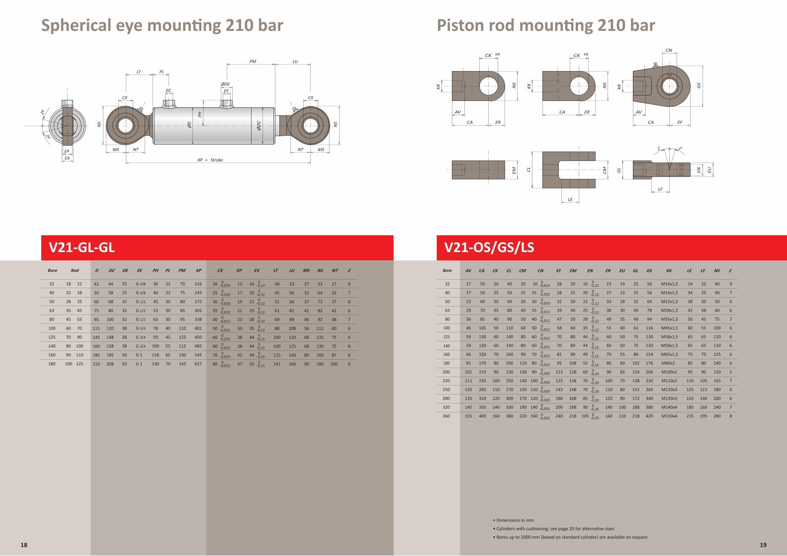
Spherical eye mounting 210 bar Piston rod mounting 210 bar
V21-GL-GL
18 19
V21-OS/GS/LS
XP + StrokeEXEP
LT
NTMS
CX
PL
LU
ØDE
PM
ØD
PH
NS
NT MS
CX
NS
EE EE
Zº
Zº
LE
ERCA
LF
CK E8 CK E8
EFERCA CA
KKKKKK NS
NS
GS
EUENGL
CMCLEM
AV AV
CN
ZZ
LE
ERCA
LF
CK E8 CK E8
EFERCA CA
KKKKKK NS
NS
GS
EUENGL
CMCL
EM
AV AV
CN
CLCKCAAV EM
17
23
EN
17
29
36
46
GL GSEF
Z
LF NS
59
59
66
81
101
111
125
CM
135
145
155
KK
50
60
50
70
85
105
130
150
170
210
235
265
310
M16x1,5
M16x1,5
25 56
25 56
61
75
86
102
124
138
116
130
OS/GS/LS Zuigerstangbevestigingen
154
176
350
400
25
30
20
35
40
50
60
70
80
90
100
110
120
140
160
50
60
40
80
90
110
140
160
200
230
250
270
300
330
380
25
30
20
40
50
60
80
90
110
130
140
150
170
190
220
210 bar320 bar
25
30
20
40
50
60
80
90
108
128
138
148
168
188
218
20
M28x1,5
M35x1,5
M45x1,5
M58x1,5
M65x1,5
M80x2
M100x2
M110x2
M120x3
M130x3
M140x4
M150x4
206
230
152
172
188
218
265
340
380
420
28
28
58
70
82
95
113
125
143
180
200
240
32
39
47
Z
23
28
19
30
35
40
50
55
60
65
70
80
90
100
EU
25
25
55
65
75
80
90
105
115
140
40
32 64
78
49 94
160
195
30
38
45
40
40
100
110
125
140
150
165
180
200
240
280
50
Piston rod mountings
60
75
22
16
25
28
35
44
49
55
60
70
70
85
90
105
ER
23
27
55
60
70
80
90
100
110
120
140
160
33
38
49
M22x1,5
110
155
125
110
95
85
75
65
60
50
185
215
42
38
34
LE
24
Z
9
7
6
6
7
6
6
6
6
5
7
6
6
7
8
32
40
50
63
80
100
160
180
200
220
250
280
320
360
125
140
Bore
Befestigungen an der Kolbenstange
25
30
CN
20
35
40
50
60
70
80
90
100
110
120
140
160
0-0,0100
-0,0100
-0,0100
-0,0120
-0,0120
-0,0120
-0,015
0-0,0150
-0,0150
-0,0200
-0,0200
-0,0200
-0,0200
-0,025
0-0,025
0-0,12
0-0,120
-0,120
-0,120
-0,120
-0,120
-0,15
130 75 13060 140 80 80 M58x1,570 50 65 11044 60 65 660 0-0,015
0-0,150
-0,150
-0,150
-0,200
-0,200
-0,200
-0,200
-0,250
-0,25
• Dimensions in mm
• Cylinders with cushioning; see page 20 for alternative sizes
• Bores up to 1000 mm (based on standard cylinder) are available on request
XP + StrokeEXEP
LT
NTMS
CX
PL
LU
ØDE
PM
ØD
PH
NS
NT MS
CX
NS
EE EE
40
Bore Rod
22 28
50 28 35
63
80
100
125
140
160
180
D DE EE PH PL PM XP
50
60
25
32
40
45
22
30
75
80
245
272
V21-OD Oog aan bodem
35
45
60
70
80
90
100
45
55
70
90
100
110
125
75
95
115
145
160
185
210
32
32
38
38
38
50
50
G 1/2
G 1
G 1
53
63
78
93
100
118
130
30
30
40
45
55
65
70
85
95
110
125
115
130
145
302
338
401
450
485
545
627
Eye mounting
G 1/2
G 3/8
G 1/2
G 3/4
G 3/4
G 3/4
32 18 22 42 25 G 3/8 36 22 70 216
210 bar
Schwenkauge am Zylinderboden
Zº
Zº
-0,0100
CX
25
30
35
40
50
60
60
70
80
20 16
20
22
25
28
35
44
44
49
55
EX LT
45
51
61
69
88
100
100
115
141
38
NS
64
73
82
92
112
135
135
160
180
53
NT
32
37
42
48
60
75
75
87
100
2713
17
19
21
23
30
38
38
42
47
MS
32
37
41
46
56
68
68
80
90
27
LU
60
66
81
89
108
120
125
140
166
53
EP Z
7
6
6
7
6
6
6
6
6
90-0,12
0-0,015
0-0,015
0-0,015
0-0,015
0-0,012
0-0,012
0-0,012
0-0,010
0-0,010
0-0,120
-0,120
-0,120
-0,120
-0,120
-0,150
-0,150
-0,150
-0,15
80
185
208
68
58
100
120
148
158
44
DC
ØD
C
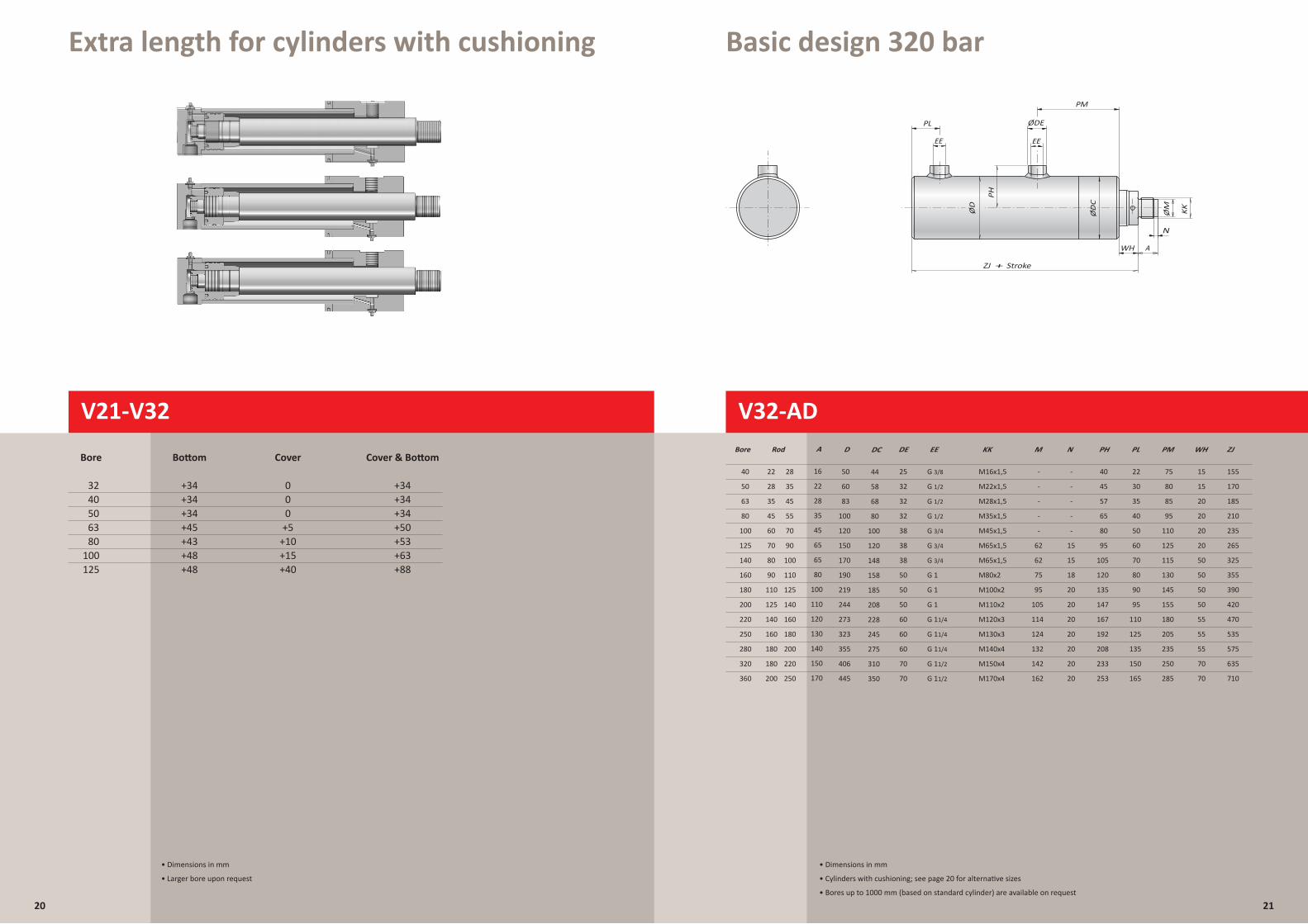
Extra length for cylinders with cushioning Basic design 320 bar
20 21
ZJ + Slag/Stroke/Hub
PL
N
A
ØDE
ØD
PH
ØM KK
EE
WH
PM
EE
V32-AD Basisuitvoering
GrundausfÅhrung
40
Bore Rod
22 28
50 28 35
63
80
100
125
140
160
180
200
220
250
280
320
360
EE KK M N PH PL PM WH ZJ
M16x1,5
M22x1,5
- -
- -
40
45
22
30
75
80
15
15
155
170
Basic design
35
45
60
70
80
90
110
125
140
160
180
180
200
45
55
70
90
100
110
125
140
160
180
200
220
250
A
16
22
28
35
45
65
65
80
100
110
120
130
140
150
170
D
50
60
83
100
120
150
170
190
219
244
273
323
355
406
445
DE
25
32
32
32
38
38
38
50
50
50
60
60
60
70
70
M28x1,5
M35x1,5
M45x1,5
M65x1,5
M65x1,5
M80x2
M100x2
M110x2
M120x3
M130x3
M140x4
M150x4
M170x4
57
65
80
95
105
120
135
147
167
192
208
233
253
35
40
50
60
70
80
90
95
110
125
135
150
165
85
95
110
125
115
130
145
155
180
205
235
250
285
20
20
20
20
50
50
50
50
55
55
55
70
70
185
210
235
265
325
355
390
420
470
535
575
635
710
-
- -
-
- -
62
62
75
95
105
114
124
132
142
162
15
18
15
20
20
20
20
20
20
20
G 1/2
G 1
G 1
G 1
G 11/4
G 11/4
G 11/4
G 11/2
G 11/2
G 1/2
G 3/8
G 1/2
G 3/4
G 3/4
G 3/4
320 bar
R
80
185
208
228
245
275
310
350
68
58
100
120
148
158
44
DC
• Dimensions in mm
• Cylinders with cushioning; see page 20 for alternative sizes
• Bores up to 1000 mm (based on standard cylinder) are available on request
V21-V32
Bore Bottom Cover Cover & Bottom
32 +34 0 +34 40 +34 0 +34 50 +34 0 +34 63 +45 +5 +50 80 +43 +10 +53 100 +48 +15 +63 125 +48 +40 +88
• Dimensions in mm
• Larger bore upon request
V32-AD
ZJ + Stroke
WH
PL ØDE
ØD
PH
ØM KK
PM
N
A
EE EE
ØD
C
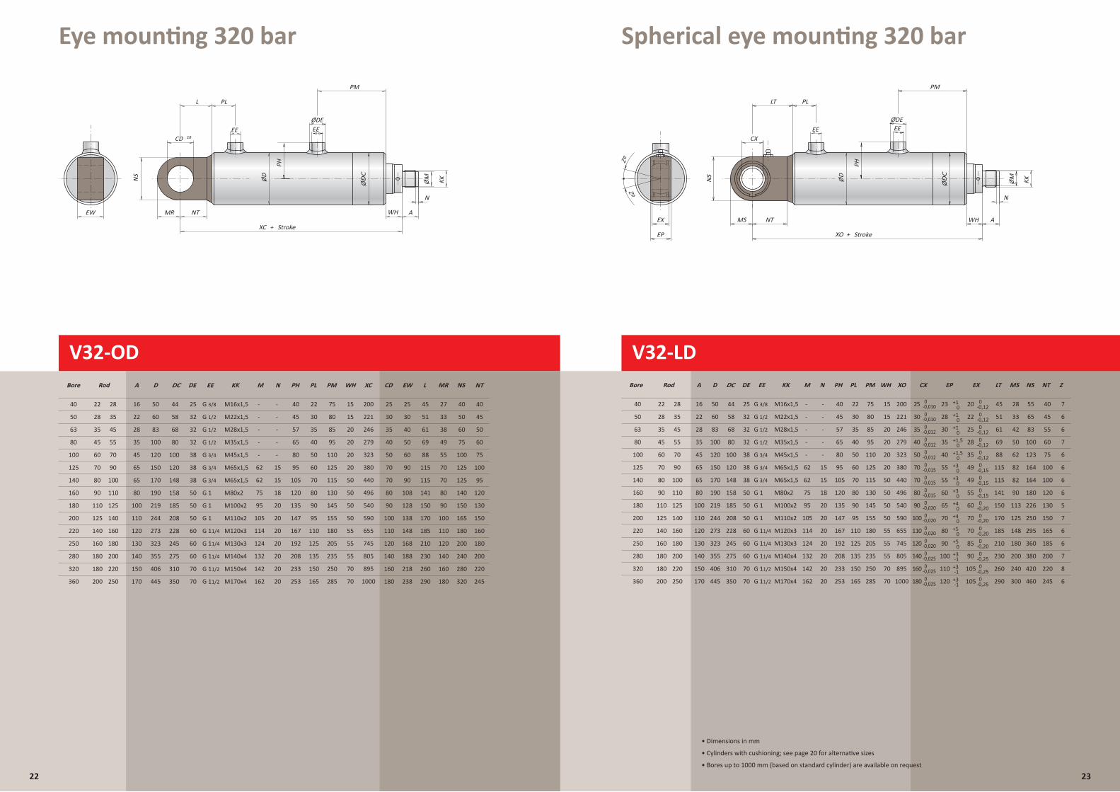
Eye mounting 320 bar Spherical eye mounting 320 bar
V32-OD
22
LT
XO + Stroke
CX
MS NT
EP
EX WH A
PL
ØDE
PM
N
EE EE
KKØMØD
PH
NS
Zº
Zº
XC + Stroke
EW
L
NTMR
CD E8
WH
PL
ØDE
PM
KKØMØD
PH
NS
N
A
EE EE
XC + Stroke
EW
L
NTMR
CD E8
PL
N
A
ØDE
ØD
ØM KK
PH
NS
EE
WH
PM
EE
V32-OD
40
Bore Rod
22 28
50 28 35
63
80
100
125
140
160
180
200
220
250
280
320
360
D DE KK M N PH PL PM WH XC
50
60
25
32
M16x1,5
M22x1,5
- -
- -
40
45
22
30
75
80
15
15
Gaffel aan bodem
Clevis mounting
200
221
35
45
60
70
80
90
110
125
140
160
180
180
200
45
55
70
90
100
110
125
140
160
180
200
220
250
A
16
22
28
35
45
65
65
80
100
110
120
130
140
150
170
83
100
120
150
170
190
219
244
273
323
355
406
445
32
32
38
38
38
50
50
50
60
60
60
70
70
M28x1,5
M35x1,5
M45x1,5
M65x1,5
M65x1,5
M80x2
M100x2
M110x2
M120x3
M130x3
M140x4
M150x4
M170x4
57
65
80
95
105
120
135
147
167
192
208
233
253
35
40
50
60
70
80
90
95
110
125
135
150
165
85
95
110
125
115
130
145
155
180
205
235
250
285
20
20
20
20
50
50
50
50
55
55
55
70
70
246
279
323
380
440
496
540
590
655
745
805
895
1000
-
- -
-
- -
62
62
75
95
105
114
124
132
142
162
15
18
15
20
20
20
20
20
20
20
EE
G 1/2
G 1
G 1
G 1
G 11/4
G 11/4
G 11/4
G 11/2
G 11/2
G 1/2
G 3/8
G 1/2
G 3/4
G 3/4
G 3/4
9070 115 12570 100
238180 290 320180 245
EW
25
30
40
50
60
90
108
128
138
148
168
188
218
25
30
35
40
50
70
80
90
100
110
120
140
160
CD L
45
51
61
69
88
115
141
150
170
185
210
230
260
320 bar
MR
27
33
38
49
55
NS
40
50
60
75
100
125
140
150
165
180
200
240
280
70
80
90
100
110
120
140
160
NT
40
45
50
60
75
95
120
130
150
160
180
200
220
R
Gabel am Zylinderboden
80
185
208
228
245
275
310
350
68
58
100
120
148
158
44
DC
V32-LD
XO + Stroke
LT
CX
EP
EX MS
PL
NT
N
A
ØDE
ØD
ØM KKNS
PH
EE
WH
PM
EE
70
40
Bore
0
V32-LD
Rod
22 28
50 28 35
63
80
100
125
140
160
180
200
220
250
280
320
360
49
M N PH PL PM WH XO
- -
- -
40
45
22
30
75
80
15
15
200
221
35
Gelenkoog aan bodem
+3
Spherical eye mounting
45
60
70
80
90
110
125
140
160
180
180
200
45
55
70
90
100
110
125
140
160
180
200
220
250
A
16
22
28
35
45
65
65
80
100
110
120
130
140
150
170
D
50
60
83
100
120
150
170
190
219
244
273
323
355
406
445
DE
25
32
32
32
38
38
38
50
50
50
60
60
60
70
70
KK
M16x1,5
M22x1,5
M28x1,5
M35x1,5
M45x1,5
M65x1,5
M65x1,5
M80x2
M100x2
M110x2
M120x3
M130x3
M140x4
M150x4
M170x4
57
65
80
95
105
120
135
147
167
192
208
233
253
35
40
50
60
70
80
90
95
110
125
135
150
165
85
95
110
125
115
130
145
155
180
205
235
250
285
20
20
20
20
50
50
50
50
55
55
55
70
70
246
279
323
380
440
496
540
590
655
745
805
895
1000
-
- -
-
- -
62
62
75
95
105
114
124
132
142
162
15
18
15
20
20
20
20
20
20
20
EE
G 1/2
G 1
G 1
G 1
G 11/4
G 11/4
G 11/4
G 11/2
G 11/2
G 1/2
G 3/8
G 1/2
G 3/4
G 3/4
G 3/4 115 164 10055 82
70 49 115 164 10055 82
180 105 290 460 245300120
0
-1+3-1
+1
CX
25
30
35
40
50
-1+3
80
90
100
110
120
140
160
20
22
25
28
35
55
60
70
70
85
90
105
EX LT
45
51
61
69
88
141
150
170
185
210
230
260
NS
55
65
83
100
123
180
226
250
295
360
380
420
-0,010
NT
40
45
55
60
75
120
130
150
165
185
200
220
23
28
30
35
40
60
65
70
80
90
MS
28
33
42
50
62
90
113
125
148
180
200
240
100
110
EP
320 bar
Zº
Zº
Z
6
6
6
7
6
6
7
6
6
5
7
6
6
7
8
0+1
0+1
0+1,5
0+1,5
+30
+30
+40
+40
+50
+50
+30
R
Gelenkauge am Zylinderboden
0-0,12
0-0,010
0-0,12
0-0,012
0-0,12
0-0,012
0-0,12
0-0,012
0-0,12
0-0,015
0-0,15
0-0,015
0-0,15
-0,0250
0-0,020
0-0,020
0-0,020
0-0,020
0-0,015
0-0,025
0-0,150
-0,200
-0,200
-0,200
-0,200
-0,250
-0,250
-0,0250
-0,25
80
185
208
228
245
275
310
350
68
58
100
120
148
158
44
DC
• Dimensions in mm
• Cylinders with cushioning; see page 20 for alternative sizes
• Bores up to 1000 mm (based on standard cylinder) are available on request
23
ØD
C
ØD
C
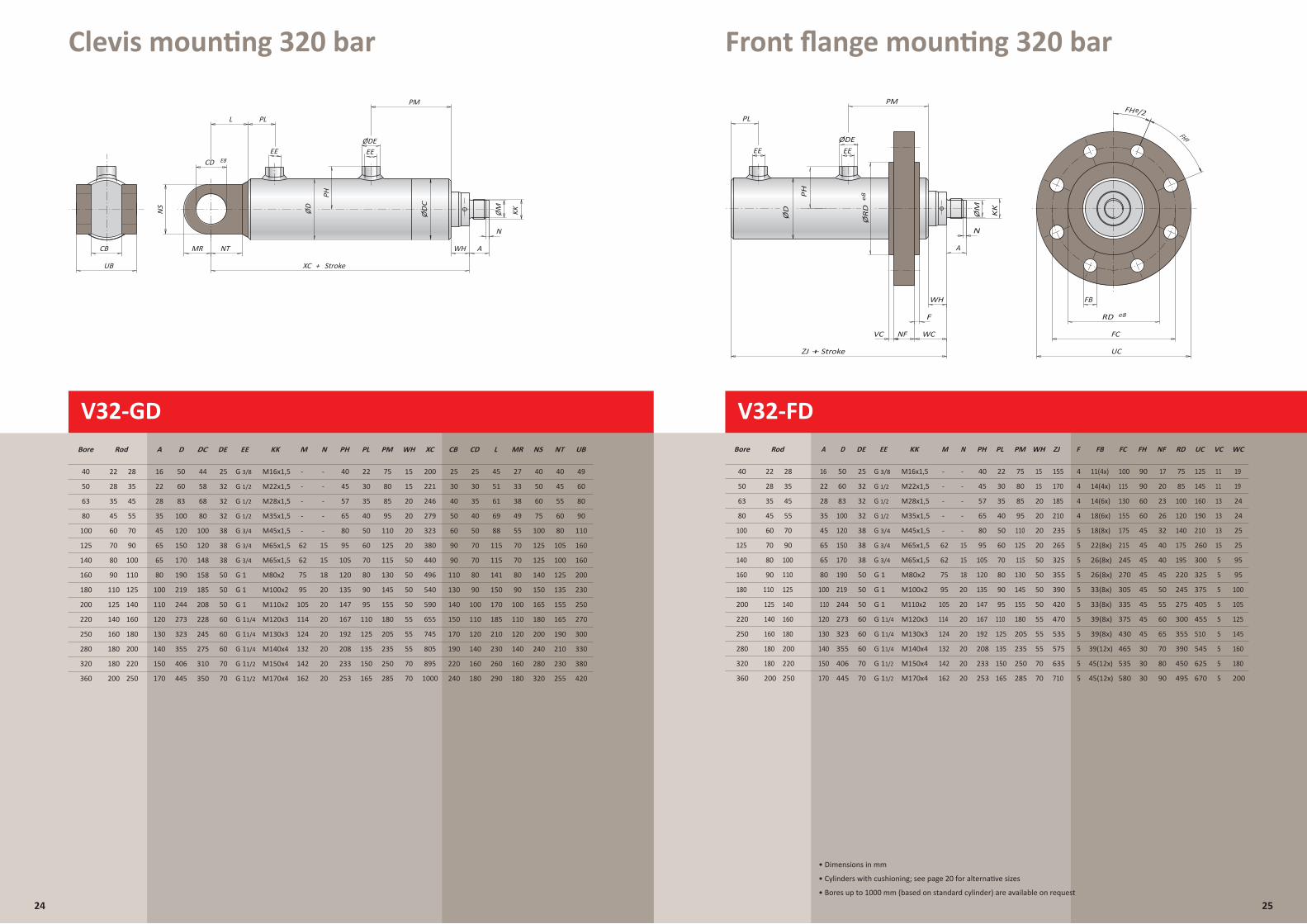
Clevis mounting 320 bar Front flange mounting 320 bar
24
XC + StrokeUB
CB
L
NTMR
CD E8
WH
PL
ØDE
ØM KK
PH
ØD
NS
PM
N
A
EE EE
ZJ + Stroke
FHº
FHº/2
FB
UC
NF FCVC
ØR
D
ØD
PH
ØM
e8
F
PL
KK
N
A
ØDEEE
WC
PM
RD e8
EE
WH
V32-GD
XC + StrokeUB
CB
L
NTMR
CD E8
PL
N
A
ØDE
ØD
ØM KK
PH
NS
EE
WH
PM
EE
V32-GD
40
Bore Rod
22 28
50 28 35
63
80
100
125
140
160
180
200
220
250
280
320
360
D M N PH PL PM WH XC
50
60
- -
- -
40
45
22
30
75
80
15
15
Gaffel aan bodem
Clevis mounting
200
221
35
45
60
70
80
90
110
125
140
160
180
180
200
45
55
70
90
100
110
125
140
160
180
200
220
250
A
16
22
28
35
45
65
65
80
100
110
120
130
140
150
170
83
100
120
150
170
190
219
244
273
323
355
406
445
DE
25
32
32
32
38
38
38
50
50
50
60
60
60
70
70
KK
M16x1,5
M22x1,5
M28x1,5
M35x1,5
M45x1,5
M65x1,5
M65x1,5
M80x2
M100x2
M110x2
M120x3
M130x3
M140x4
M150x4
M170x4
57
65
80
95
105
120
135
147
167
192
208
233
253
35
40
50
60
70
80
90
95
110
125
135
150
165
85
95
110
125
115
130
145
155
180
205
235
250
285
20
20
20
20
50
50
50
50
55
55
55
70
70
246
279
323
380
440
496
540
590
655
745
805
895
1000
-
- -
-
- -
62
62
75
95
105
114
124
132
142
162
15
18
15
20
20
20
20
20
20
20
EE
G 1/2
G 1
G 1
G 1
G 11/4
G 11/4
G 11/4
G 11/2
G 11/2
G 1/2
G 3/8
G 1/2
G 3/4
G 3/4
G 3/4
7090 115 12570 105 160
180240 290 320180 255 420
CD
25
30
35
40
50
70
80
90
100
110
120
140
160
25
30
40
50
60
90
110
130
140
150
170
190
220
CB L
45
51
61
69
88
115
141
150
170
185
210
230
260
320 bar
MR
27
33
38
49
55
NS
40
50
60
75
100
125
140
150
165
180
200
240
280
70
80
90
100
110
120
140
160
NT
40
45
55
60
80
100
125
135
155
165
190
210
230
UB
49
60
80
90
110
160
200
230
250
270
300
330
380
R
Gabel am Zylinderboden
80
185
208
228
245
275
310
350
68
58
100
120
148
158
44
DC
V32-FD
ZJ + Stroke
FHº
FHº/2
FB
UC
NF FCVC
ØR
D
ØD
PH
ØM
e8
F
PL
KK
N
A
ØDEEE
WC
PM
RD e8
EE
WH
V32-FD
40
Bore Rod
22 28
50 28 35
63
80
100
125
140
160
180
200
220
250
280
320
360
A D DE EE KK M N PH PL
100
PM WH ZJ
16
22
50
60
25
32
M16x1,5
M22x1,5
- -
- -
40
45
22
30 115
130
75
80
Frontflens
Front flange mounting
15
15
155
170
35
45
60
70
80
90
125
140
160
180
180
200
45
55
70
90
100
125
140
160
180
200
220
250
28
35
45
65
65
80
100
110
120
130
140
150
170
83
100
120
150
170
190
219
244
273
323
355
406
445
32
32
38
38
38
50
50
50
60
60
60
70
70
G 1/2
G 1
G 1
G 1
G 11/4
G 11/4
G 11/4
G 11/2
G 11/2
M28x1,5
M35x1,5
M45x1,5
M65x1,5
M65x1,5
M80x2
M100x2
M110x2
M120x3
M130x3
M140x4
M150x4
M170x4
57
65
80
95
105
120
135
147
167
192
208
233
253
35
40
50
60
70
80
90
95
110
125
135
150
165
85
95
110
125
115
130
145
155
180
155
175
215
245
FC
270
305
335
375
205 430
465
535
235
250
285
20
20
20
20
50
50
50
50
55
55
55
70
70
185
210
235
265
325
355
390
420
470
535
575
635
710
-
- -
-
- -
62
62
75
95
105
114
124
132
142
162
15
18
15
20
20
20
20
20
20
20
G 1/2
G 3/8
G 1/2
G 3/4
G 3/4
580
G 3/4
F
4 11(4x) 17
4 14(4x) 20
4 14(6x) 23
4 18(6x) 26
5 18(8x) 32
5 22(8x) 40
5 26(8x) 40
5
FB
26(8x) 45
5 33(8x) 50
5 33(8x) 55
5 39(8x) 60
5
NF
39(8x) 65
5 39(12x) 70
5 45(12x) 80
5 45(12x) 90
Flansch amZylinderkopf
90
90
60
60
45
45
45
45
45
45
45
FH
45
75
85
100
120
140
175
195
220
245
275
300
RD
355
390
450
495
30
125
145
160
190
210
260
300
325
375
405
455
UC
510
545
625
670
11
11
13
13
13
15
5
5
5
5
5
VC
5
5
5
5
19
19
24
24
25
25
95
95
100
105
125
WC
145
160
180
200
30
30
320 bar
R
110
110
• Dimensions in mm
• Cylinders with cushioning; see page 20 for alternative sizes
• Bores up to 1000 mm (based on standard cylinder) are available on request
25
ØD
C
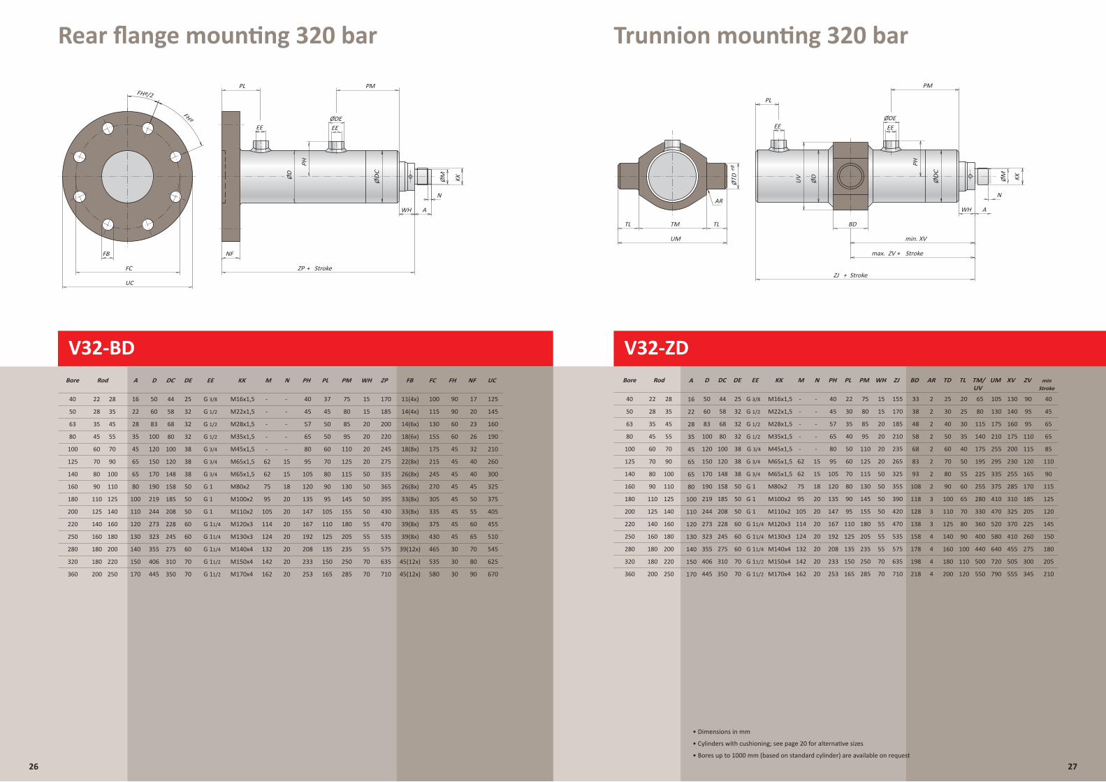
Rear flange mounting 320 bar Trunnion mounting 320 bar
V32-BD
26
ZP + Stroke
FHº
FHº/2
FB
UC
FC
PL
WH
KKØMØD
PH
N
A
ØDEEE
NF
PM
EE
ZP + Stroke
FHº
FHº/2
FB
UC
FC
PL
WH
KKØMØD
PH
N
A
ØDEEE
NF
PM
EE
40
V32-BD
Bore Rod
22 28
50 28 35
63
80
100
125
140
160
180
200
220
250
280
320
360
D DE EE M N PH PL
100
PM ZP
50
60
25
32
- -
- -
40
45
37
45 115
130
75
80
170
185
35
45
60
70
80
Bodemflens
Rear flange mounting
90
110
125
140
160
180
180
200
45
55
70
90
100
110
125
140
160
180
200
220
250
A
16
22
28
35
45
65
65
80
100
110
120
130
140
150
170
83
100
120
150
170
190
219
244
273
323
355
406
445
32
32
38
38
38
50
50
50
60
60
60
70
70
G 1/2
G 1
G 1
G 1
G 11/4
G 11/4
G 11/4
G 11/2
G 11/2
KK
M16x1,5
M22x1,5
M28x1,5
M35x1,5
M45x1,5
M65x1,5
M65x1,5
M80x2
M100x2
M110x2
M120x3
M130x3
M140x4
M150x4
M170x4
57
65
80
95
105
120
135
147
167
192
208
233
253
50
50
60
70
80
90
95
105
110
125
135
150
165
85
95
110
125
115
130
145
155
180
155
175
215
245
FC
270
305
335
375
430
465
535
205
235
250
285
200
220
245
275
335
365
395
430
470
535
575
635
710
-
- -
-
- -
62
62
75
95
105
114
124
132
142
162
15
18
15
20
20
20
20
20
20
20
G 1/2
G 3/8
G 1/2
G 3/4
580
G 3/4
11(4x) 17
14(4x) 20
14(6x) 23
18(6x) 26
18(8x) 32
22(8x) 40
26(8x) 40
FB
26(8x) 45
33(8x) 50
90
90
33(8x) 55
60
60
39(8x) 60
45
NF
45
39(8x) 65
39(12x) 70
45(12x) 80
45(12x) 90
WH
15
15
20
20
20
20
50
50
50
50
55
55
55
70
70
125
145
160
190
210
260
300
325
375
405
455
UC
510
545
625
670
45
FH
320 bar
45
45
45
45
45
30
30
30
G 3/4
R
Flansch am Zylinderboden
80
185
208
228
245
275
310
350
68
58
100
120
148
158
44
DC
ZJ + Stroke
max. ZV + Stroke
AR
min. XV
BD
UM
TL TLTM
ØTD UV
ØD
PH
ØM KK
e8
PL
N
A
ØDEEE
WH
PM
EE
V32-ZD
ZJ + Stroke
max. ZV + Stroke
AR
XVmin.UM
TL TLTM
ØTD
e8
PL
BD
N
A
ØDE
UV
KKØMØD
EE
PH
WH
PM
EE
40
Bore Rod
22 28
50 28 35
63
80
100
125
140
160
180
200
220
250
280
320
360
A DE EE KK M N PH PL PM WH ZJ
16
22
25
32
M16x1,5
M22x1,5
- -
- -
40
45
22
30
75
80
15
15
155
170
V32-ZD
320 bar
Zwenktap
Trunnion mounting
35
45
60
70
80
90
110
125
140
160
180
180
200
45
55
70
90
100
110
125
140
160
180
200
220
250
28
35
45
65
65
80
100
110
120
130
140
150
170
D
50
60
83
100
120
150
170
190
219
244
273
323
355
406
445
32
32
38
38
38
50
50
50
60
60
60
70
70
M28x1,5
M35x1,5
M45x1,5
M65x1,5
M65x1,5
M80x2
M100x2
M110x2
M120x3
M130x3
M140x4
M150x4
M170x4
57
65
80
95
105
120
135
147
167
192
208
233
253
35
40
50
60
70
80
90
95
110
125
135
150
165
85
95
110
125
115
130
145
155
180
205
235
250
285
20
20
20
20
50
50
50
50
55
55
55
70
70
185
210
235
265
325
355
390
420
470
535
575
635
710
-
- -
-
- -
62
62
75
95
105
114
124
132
142
162
15
18
15
20
20
20
20
20
20
20
G 1/2
G 1
G 1
G 1
G 11/4
G 11/4
G 11/4
G 11/2
G 11/2
G 1/2
G 3/8
G 1/2
G 3/4
G 3/4
G 3/4
BD TD TL TM/ UV
UM XV
33
38
83
93
108
118
128
138
158
178
198
218
25
30
70
80
90
100
110
125
140
160
180
40
50
60
20
25
50
55
60
65
70
80
90
100
110
30
35
40
65
80
195
225
255
280
330
360
400
440
500
115
140
175
105
130
295
335
375
410
470
520
580
640
720
175
210
255
130
140
230
255
285
310
325
370
410
48
58
68
455
505
160
175
200
200 120 550 790 555
ZV
40
45
110
90
115
125
120
145
150
180
205
65
65
85
210
AR
2
2
2
2
2
3
3
3
4
4
4
4
2
2
2
min
90
95
120
165
170
185
205
225
260
275
300
95
110
115
345
Stroke
Schwenkzapfen
80
185
208
228
245
275
310
350
68
58
100
120
148
158
44
DC
27
• Dimensions in mm
• Cylinders with cushioning; see page 20 for alternative sizes
• Bores up to 1000 mm (based on standard cylinder) are available on request
ØD
C
ØD
C
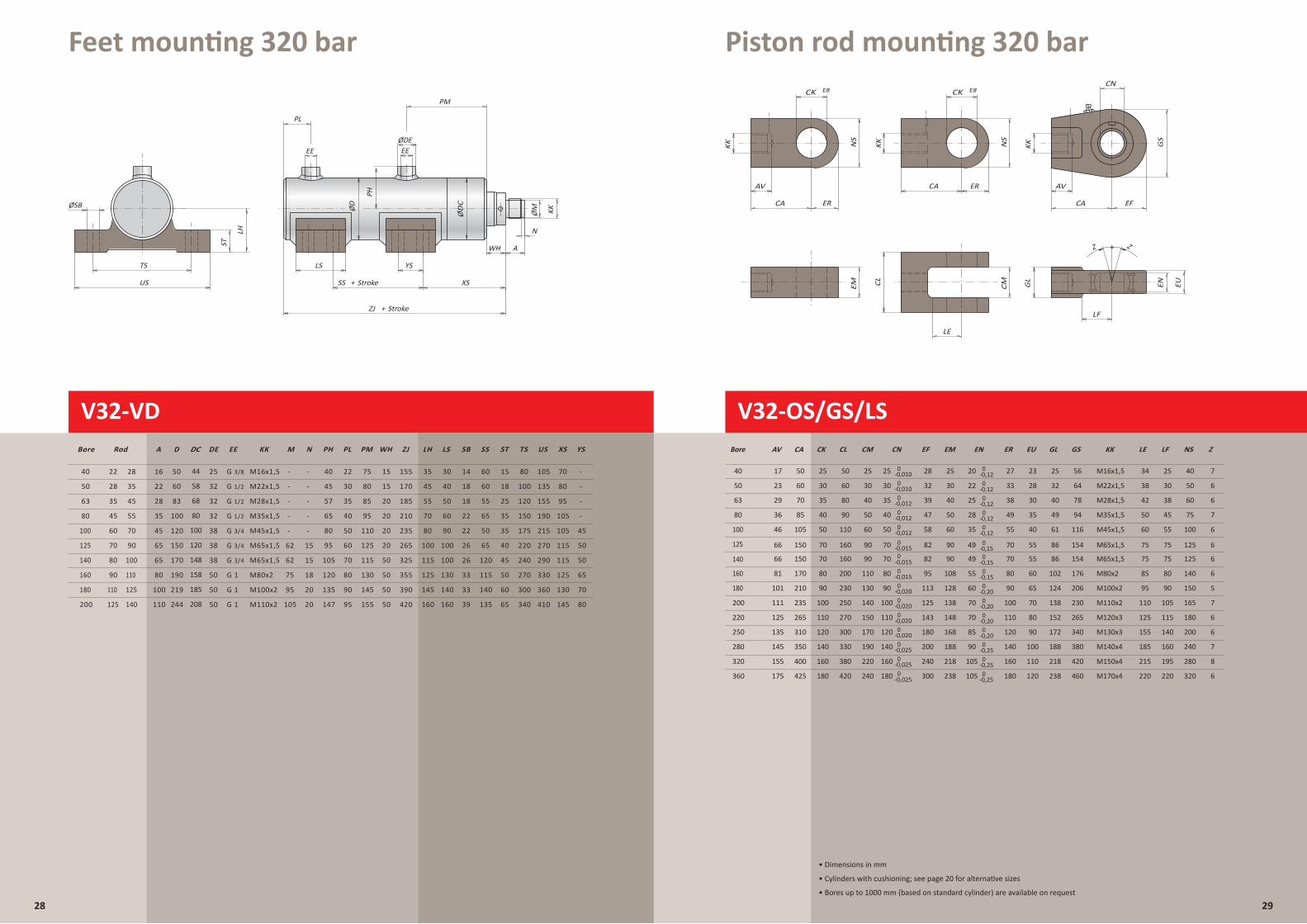
Feet mounting 320 bar Piston rod mounting 320 bar
V32-VD
28 29
• Dimensions in mm
• Cylinders with cushioning; see page 20 for alternative sizes
• Bores up to 1000 mm (based on standard cylinder) are available on request
V32-OS/GS/LS
LE
ERCA
LF
CK E8 CK E8
EFERCA CA
KKKKKK NS
NS
GS
EUENGL
CMCL
EM
AV AV
CN
CLCKCAAV EM
17
23
EN
29
36
46
GL GSEF
Z
LF NS
66
81
101
111
125
CM
135
145
155
KK
50
60
70
85
105
150
170
210
235
265
310
M16x1,525 56
61
86
102
124
138
116
OS/GS/LS Zuigerstangbevestigingen
154
176
350
400
25
30
35
40
50
70
80
90
100
110
120
140
160
50
60
80
90
110
160
200
230
250
270
300
330
380
25
30
40
50
60
90
110
130
140
150
170
190
220
210 bar320 bar
25
30
40
50
60
90
108
128
138
148
168
188
218
20
M28x1,5
M35x1,5
M45x1,5
M65x1,5
M80x2
M100x2
M110x2
M120x3
M130x3
M140x4
M150x4
M170x4
206
230
152
172
188
218
265
340
380
420
28
58
82
95
113
125
143
180
200
240
32
39
47
Z
23
28
30
35
40
55
60
65
70
80
90
100
EU
175
25
55
75
80
90
105
115
140
40
32 64
78
49 94
160
195
30
38
45
40
100
125
140
150
165
180
200
240
280
50
Piston rod mountings
60
75
22
25
28
35
49
55
60
70
70
85
90
105
ER
27
55
70
80
90
100
110
120
140
160
33
38
49
425 180 420 240 238
M22x1,5
238 460300 220 320105 180
110
120 220
155
125
110
95
85
75
60
50
185
215
42
38
34
LE Z
7
6
6
7
6
6
6
5
7
6
6
7
8
6
125
140
40
50
63
80
100
160
180
200
220
250
280
320
360
Bore
Befestigungen an der Kolbenstange
25
30
CN
35
40
50
70
80
90
100
110
120
140
160
180
-0,010
-0,010
-0,012
-0,012
-0,012
-0,015
-0,015
-0,020
-0,020
-0,020
-0,020
-0,025
-0,025
66 150 86 15470 160 90 90 M65x1,582 55 75 12549 70 75 670 -0,015
0
0
0
0
0
0
0
0
0
0
0
0
0
0
0-0,025
0
0
0
0
0
0
0
0
0
0
0
0
0
0
0
-0,12
-0,12
-0,12
-0,12
-0,12
-0,15
-0,15
-0,15
-0,20
-0,20
-0,20
-0,20
-0,25
-0,25
-0,25
SS + Stroke
ZJ + Stroke
ØSB
LS
XS
YS
US
TS
PL
N
A
ØDE
ØD
LH
ST
PH
KKØM
EE
WH
PM
EE
LE
ERCA
LF
CK E8 CK E8
EFERCA CA
KKKKKK NS
NS
GS
EUENGL
CMCLEM
AV AV
CN
ZZZJ + Stroke
SS + Stroke
PL
LS
XS
YS
US
TS
ØSB
N
A
ØDE
ØD
ØM KK
ST
LH
PH
EE
WH
PM
EE
40
Bore Rod
22 28
50 28 35
63
80
100
125
140
160
180
200
70
V32-VD
DE EE M N PH PL PM WH ZJ
25
32
- -
- -
40
45
22
30
75
80
15
15
155
170
Voeten
320 bar
35
45
60
70
80
90
110
125
45
55
70
90
100
110
125
140
A
16
22
28
35
45
65
65
80
100
110
D
50
60
83
100
120
150
170
190
219
244
32
32
38
38
38
50
50
50
G 1/2
G 1
G 1
G 1
KK
M16x1,5
M22x1,5
M28x1,5
M35x1,5
M45x1,5
M65x1,5
M65x1,5
M80x2
M100x2
M110x2
57
65
80
95
105
120
135
147
Feet mounting
35
40
50
60
70
80
90
95
TS US XS
85
95
110
125
115
130
145
155
80
100
120
150
175
20
20
20
20
50
50
50
50
220
240
270
300
340
185
210
235
265
325
355
390
420
105
135
155
190
215
-
- -
-
- -
62
62
75
95
105
270
290
330
360
410
15
18
15
20
20
80
95
105
105
115
115
G 1/2
G 3/8
G 1/2
G 3/4
G 3/4
G 3/4
Fu·befestigung
LS
30 14 60 15 -
45
55
70
80
100
115
125
145
160
125
130
145
LH
35
40
50
60
90
100
100
130
140
160
SB
18
18
22
22
26
26
33
33
39
SS
60
55
65
50
65
120
115
140
135
ST
18
25
35
35
40
45
50
60
65
YS
-
-
-
45
50
50
65
70
80
80
185
208
68
58
100
120
148
158
44
DCØ
DC
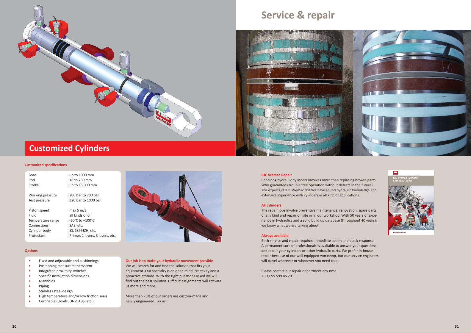
Our job is to make your hydraulic movement possibleWe will search for and find the solution that fits your equipment. Our specialty is an open mind, creativity and a proactive attitude. With the right questions asked we will find out the best solution. Difficult assignments will activate us more and more.
More than 75% of our orders are custom-made andnewly engineered. Try us...
Customized Cylinders
Customized specifications
Bore : up to 1000 mm Rod : 18 to 700 mm Stroke : up to 15.000 mm
Working pressure : 200 bar to 700 bar Test pressure : 320 bar to 1000 bar
Piston speed : max 5 m/s Fluid : all kinds of oil Temperature range : -60˚C to +100˚C Connections : SAE, etc. Cylinder body : SS, S355JZH, etc. Protectant : Primer, 2 layers, 3 layers, etc.
Options
• Fixed and adjustable end cushionings • Positioning measurement system • Integrated proximity switches • Specific installation dimensions • Manifolds • Piping • Stainless steel design • High temperature and/or low friction seals • Certifiable (Lloyds, DNV, ABS, etc.)
IHC Vremac RepairRepairing hydraulic cylinders involves more than replacing broken parts. Who guarantees trouble free operation without defects in the future? The experts of IHC Vremac do! We have sound hydraulic knowledge and extensive experience with cylinders in all kind of applications.
All cylinders The repair jobs involve preventive maintenance, renovation, spare parts of any kind and repair on site or in our workshop. With 50 years of expe-rience in hydraulics and a solid build up database (throughout 40 years); we know what we are talking about.
Always availableBoth service and repair requires immediate action and quick response. A permanent core of professionals is available to answer your questions and repair your cylinders or other hydraulic parts. We prefer in-house repair because of our well equipped workshop, but our service engineers will travel wherever or whenever you need them.
Please contact our repair department any time.T +31 55 599 45 20
TitelSubtitelIHC Vremac CylindersCompany Profile
Service & repair
30 31

Notes
............................................................................................................................................................................................
............................................................................................................................................................................................
............................................................................................................................................................................................
............................................................................................................................................................................................
............................................................................................................................................................................................
............................................................................................................................................................................................
............................................................................................................................................................................................
............................................................................................................................................................................................
............................................................................................................................................................................................
............................................................................................................................................................................................
............................................................................................................................................................................................
............................................................................................................................................................................................
............................................................................................................................................................................................
............................................................................................................................................................................................
............................................................................................................................................................................................
............................................................................................................................................................................................
............................................................................................................................................................................................
............................................................................................................................................................................................
............................................................................................................................................................................................
............................................................................................................................................................................................
............................................................................................................................................................................................
............................................................................................................................................................................................
............................................................................................................................................................................................
............................................................................................................................................................................................
............................................................................................................................................................................................
............................................................................................................................................................................................
............................................................................................................................................................................................
............................................................................................................................................................................................
............................................................................................................................................................................................
............................................................................................................................................................................................
............................................................................................................................................................................................
............................................................................................................................................................................................
............................................................................................................................................................................................
............................................................................................................................................................................................
............................................................................................................................................................................................
............................................................................................................................................................................................
............................................................................................................................................................................................
............................................................................................................................................................................................
............................................................................................................................................................................................
............................................................................................................................................................................................
............................................................................................................................................................................................
............................................................................................................................................................................................
............................................................................................................................................................................................
............................................................................................................................................................................................
............................................................................................................................................................................................
............................................................................................................................................................................................
............................................................................................................................................................................................
............................................................................................................................................................................................
............................................................................................................................................................................................
............................................................................................................................................................................................
............................................................................................................................................................................................
............................................................................................................................................................................................
............................................................................................................................................................................................
............................................................................................................................................................................................
............................................................................................................................................................................................
............................................................................................................................................................................................
32 33
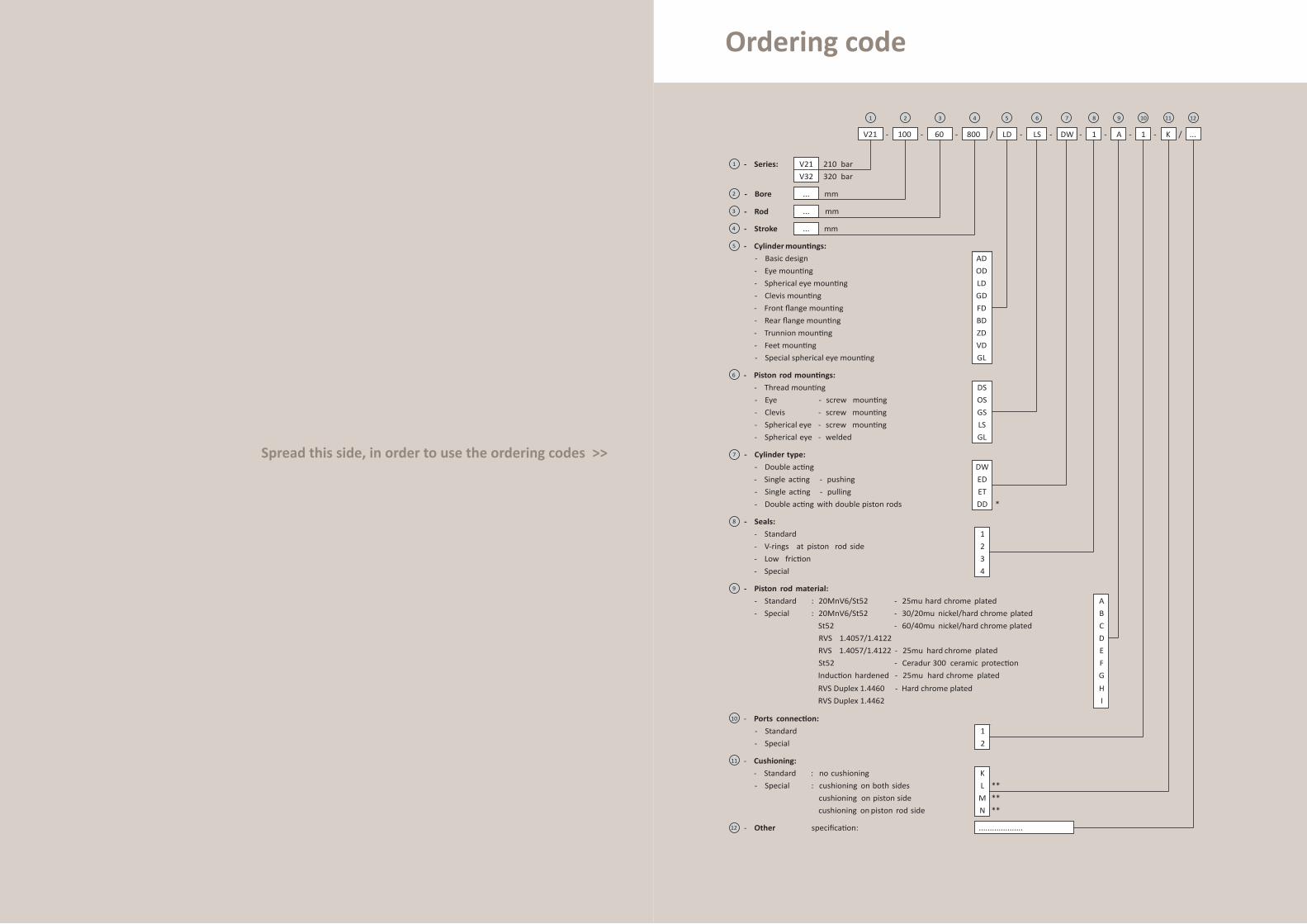
Spread this side, in order to use the ordering codes >>
Ordering code
10
11
12
- Basic design
- Eye mounting
- Spherical eye mounting
- Clevis mounting
- Front flange mounting
- Rear flange mounting
- Trunnion mounting
- Feet mounting
- Special spherical eye mounting
- Cushioning:
- Series:
...
V21 100 60 800
1
LD LS DW 1 A
V21
1
V32
K
1 2 3 4 5 6 7 8 9 10 11
- Bore
210 bar
320 bar
- - - - - - - - -/
2
...- Rod3
...- Stroke4
5
- Thread mounting
- Eye - screw mounting
- Clevis - screw mounting
- Spherical eye - screw mounting
- Spherical eye - welded
AD
OD
LD
GD
FD
BD
ZD
VD
GL
6
DS
OS
GS
LS
GL
- Piston rod mountings:
- Cylindermountings:
- Double acting
- Single acting - pushing
- Single acting - pulling
- Double acting with double piston rods
7 - Cylinder type:
- Standard
- V-rings at piston rod side
- Low friction
- Special
- Seals:8
- Standard : 20MnV6/St52 - 25mu hard chrome plated
- Special : 20MnV6/St52 - 30/20mu nickel/hard chrome plated
St52 - 60/40mu nickel/hard chrome plated
RVS 1.4057/1.4122
RVS 1.4057/1.4122 - 25mu hard chrome plated
St52 - Ceradur 300 ceramic protection
Induction
RVS Duplex 1.4460
RVS Duplex 1.4462
- Hard chrome plated
hardened - 25mu hard chrome plated
- Piston rod material:9
- Ports connection:
- Standard
- Special
- Standard : no cushioning
- Special : cushioning on both sides
cushioning on piston side
cushioning on piston rod side
*
DW
ED
ET
DD
1
2
3
4
1
2
E
A
B
C
D
F
G
H
I
K
L
M
N
**
**
**
- Other specification:
mm
mm
mm
...
12
/
....................

TangguDalian
Houston, TXWayne, NJ
Riding MillBlandford Forum
Verberie KomarnoBelgrade
Aberdeen
Lagos
St. Petersburg
DubaiNew Delhi
Mumbai
Singapore
Guangzhou
TianjinBeijing
Cape Town
The Netherlands
Rijeka
Delfgauw
Krimpen a/d
IJssel
KinderdijkSlie
drecht
Hardinxveld-Giesse
ndam
Heusden
Dordrecht
Goes
Emmeloord
Apeldoorn
Alblasserdam
IHC Vremac Cylinders B.V.
P.O. Box 481, 7300 AL ApeldoornLaan van Malkenschoten 95,7333 NP ApeldoornThe Netherlands
T + 31 55 599 45 20F + 31 55 599 45 [email protected]
Head Office – The Netherlands
Sliedrecht
Shipyards – The Netherlands
Hardinxveld-GiessendamHeusdenKinderdijkKrimpen aan den IJsselSliedrecht
Shipyards – P.R. of China
Dalian
Sites – The Netherlands
AlblasserdamApeldoornDelfgauwDordrechtEmmeloordGoesHardinxveld-GiessendamHeusdenKinderdijkSliedrecht
Sites – Europe
Blandford Forum – United KingdomKomarno – SlovakiaRiding Mill – United KingdomRijeka – CroatiaVerberie – France
Sites – USA
Houston, TXWayne, NJ
Representative offices
Beijing – P.R. of ChinaNew Delhi – IndiaSt. Petersburg – Russia
Regional IHC Organizations worldwide
Dubai – United Arab EmiratesKinderdijk – The NetherlandsLagos – NigeriaMumbai – IndiaSingapore – Republic of SingaporeTianjin/Tanggu & Guangzhou – P.R. of China