Embed Size (px)
Citation preview

KSC-GP-435, Volume IIRevision C
KDP-KSC-T-5406 Rev Basic
ENGINEERING DRAWING PRACTICES VOLUME II OF II
FACILITIES
July 6, 2020
Engineering Directorate
NOT EXPORT CONTROLLED
This document has been reviewed by the KSC Export Control Office and it has been determined that it does not meet the criteria for control under the International Traffic in Arms Regulations (ITAR) or
Export Administration Regulations (EAR).
Reference EDR Log #: 7605 NASA KSC Export Control Office, (321) 867-9209

KSC-GP-435, Volume IIRevision C
JOHN F. KENNEDY SPACE CENTER, NASA
ENGINEERING DRAWING PRACTICES VOLUME II OF II
FACILITIES
Approved by:
_________________________________Shawn M. QuinnDirector, Engineering
July 6, 2020
SHAWN QUINNDigitally signed by SHAWN QUINNDate: 2020.07.06 14:58:44 -04'00'

KSC-GP-435, Volume IIRevision C
ii
RECORD OF REVISIONS/CHANGES
REVLTR
CHGNO. DESCRIPTION DATE
Basic Issue February 1, 19731 Changed pages ii through ix and 8-1 through 8-10 June 6, 1973
A General Revision March 30, 1992B Revised to incorporate the metric system March 15, 1993C Replaced ‘shall’ with ‘must’; use of ‘shall’ was eliminated
Added the Acronyms and Abbreviations tableAdded Section 1.5, Applicable DocumentsClarified use of ‘may’, ‘must’, and ‘should’ in Section 1.6, Definitions Added “Line Types” to Section 1.6, Definitions Added Section 2.5, Dimensioning Rules, and associated diagram Updated Section 4.4.1, Standard Sheet Identification, to include new tables and diagramsUpdated Section 4.5, Title Block Signature Blocks, to reflect current signature blocksAdded Section 10, Life Safety and Fire Protection Drawings Updated and replaced example forms in Section 13, Forms, to include revised coversheet for discipline sheet, and sample title block signature blocks sheetOther minor clarifications and correctionsIncororated all Change Notices
July 6, 2020

KSC-GP-435, Volume IIRevision C
iii
CONTENTS
1. INTRODUCTION............................................................................................1Scope.............................................................................................................1 Drafting Methods............................................................................................1 Facilities Drawing Requirements ....................................................................1
1.3.1 Facility Design Package.................................................................................1 1.3.2 Typical Facility Drawings................................................................................2 1.3.3 Facility Drawing Set .......................................................................................2
Measurement Units ........................................................................................3 Applicable Documents....................................................................................3 Definitions ......................................................................................................5
2. GENERAL DRAFTING PRACTICES..............................................................8
Scope.............................................................................................................8 Signatures, Approvals, Dates, and Block Entries............................................8
2.2.1 Computer-Aided-Design (CAD) Drawing ........................................................8 2.2.2 Revision Blocks..............................................................................................8 2.2.3 Title Blocks.....................................................................................................9
Drawing Scale................................................................................................9 2.3.1 Selection of Scale ..........................................................................................9 2.3.2 Indication of Scale..........................................................................................9 2.3.3 Not to Scale ...................................................................................................9
Dimensioning and Tolerances ........................................................................9 Dual Dimensioning .......................................................................................11Match Lines..................................................................................................11Metric Values ...............................................................................................11CAD Software Requirements .......................................................................11Legibility and Reproducibility ........................................................................12Drawing Notes .............................................................................................12
2.10.1 Drawing Note Types.....................................................................................12 2.10.2 Note Language Style....................................................................................13 2.10.3 Note Contents ..............................................................................................14 2.10.4 Material Notes..............................................................................................14
Column Grid System ....................................................................................15Reference Dimension and Notes..................................................................15Quality Check (Recommended) ...................................................................15Overall Appearance .....................................................................................15Title Blocks...................................................................................................16Drawing Practices ........................................................................................16Revisions .....................................................................................................16
3. DRAWING FORMAT....................................................................................17
Size, Format, Title Block, and Material .........................................................17Required Formats ........................................................................................17
3.2.1 Zoning of Drawings ......................................................................................17Security Classification and Notation .............................................................17Notice...........................................................................................................17KSC Contractor Drawing Formats ................................................................18

KSC-GP-435, Volume IIRevision C
iv
4. DRAWING TITLES AND IDENTIFICATION .................................................18
Scope...........................................................................................................18Title Requirements .......................................................................................18
4.2.1 Location .......................................................................................................18 4.2.2 Basic Name..................................................................................................19 4.2.3 Description ...................................................................................................19 4.2.4 Subtitle.........................................................................................................19
Identification Requirements..........................................................................194.3.1 Drawing Number ..........................................................................................19 4.3.2 Records .......................................................................................................19 4.3.3 Transferring Design Responsibility to another Organization .........................19
Sheet Identification.......................................................................................194.4.1 Standard Sheet Identification .......................................................................20
Title Block Signature Blocks.........................................................................21
5. CIVIL DRAWINGS .......................................................................................21
Scope...........................................................................................................21Definition of Civil Drawings...........................................................................21Types of Civil Drawings................................................................................21Preliminary Field Investigation and Study Drawing.......................................22Topographic Map .........................................................................................22Master Plan Drawing....................................................................................23Site Plan Drawing.........................................................................................23Excavation Plan Drawing .............................................................................24Finish – Grading Drawing.............................................................................24Plan and Profile Drawing..............................................................................25
5.10.1 Requirements...............................................................................................25Road and Paving Drawing............................................................................27Symbols for Civil Drawings...........................................................................28
6. ARCHITECTURAL DRAWINGS...................................................................28Scope...........................................................................................................28Types of Architectural Drawings...................................................................28
6.2.1 Preliminary Study Drawing ...........................................................................28 6.2.2 Presentation Drawing...................................................................................28 6.2.3 Pictorial Drawing ..........................................................................................29
Architectural Working Drawings ...................................................................296.3.1 Floor Plans Requirements............................................................................296.3.2 Elevations ....................................................................................................30 6.3.3 Sections .......................................................................................................30 6.3.4 Details..........................................................................................................31 6.3.5 Roof Plan .....................................................................................................31 6.3.6 Reflected Ceiling Fan...................................................................................31 6.3.7 Schedules ....................................................................................................32
Miscellaneous Delineations..........................................................................32Architectural Symbols...................................................................................33
7. STRUCTURAL DRAWINGS.........................................................................33Scope...........................................................................................................33

KSC-GP-435, Volume IIRevision C
v
Definition of Structural Drawings ..................................................................33Structural Concrete Drawings.......................................................................33
7.3.1 Foundation Drawing .....................................................................................33 7.3.2 Floor Plan.....................................................................................................34 7.3.3 Elevation ......................................................................................................35 7.3.4 General Detail Drafting Practices .................................................................35
Structural Steel Drawings.............................................................................367.4.1 Column Grid.................................................................................................36 7.4.2 Structural Steel Plan ....................................................................................37 7.4.3 Framing Section or Elevation .......................................................................37 7.4.4 Connections and Details ..............................................................................38
Symbols for Structural Drawings ..................................................................397.5.1 Reinforced Concrete Construction Symbols .................................................39 7.5.2 Symbols for Rolled Shapes ..........................................................................39 7.5.3 Symbols for Combinations of Structural Shapes...........................................39 7.5.4 Timber Construction Symbols ......................................................................39 7.5.5 Flat-Rolled Metals – Thickness Callouts.......................................................39
8. MECHANICAL DRAWINGS .........................................................................40
Scope...........................................................................................................40Definition of Mechanical Drawings ...............................................................40Flow Diagrams .............................................................................................40Control Diagrams .........................................................................................40Piping Drawings ...........................................................................................41Heating, Ventilating, and Air-Conditioning Drawings ....................................42Symbols for Mechanical Drawings ...............................................................43
9. ELECTRICAL DRAWINGS ..........................................................................43General Requirements .................................................................................44Diagrams......................................................................................................45
9.2.1 Block Diagram..............................................................................................46 9.2.2 Single-Line Diagram.....................................................................................47 9.2.3 Schematic and Connection Diagrams ..........................................................48
Electrical Site Plans .....................................................................................489.3.1 Electrical-Equipment Arrangement...............................................................51 9.3.2 Building Load-Center Substation..................................................................51 9.3.3 Building or Structure Electrical-Power Distribution (Interior) .........................51 9.3.4 Exterior Power Distribution...........................................................................52 9.3.5 Building or Structure Lighting (Interior) .........................................................52 9.3.6 Exterior Lighting ...........................................................................................53 9.3.7 Building or Structure Grounding (Interior) .....................................................53 9.3.8 Exterior Grounding .......................................................................................54 9.3.9 Cathodic Protection......................................................................................54 9.3.10 Building or Structure Communications .........................................................55 9.3.11 Exterior Communications .............................................................................55
Functional Designations ...............................................................................55
10. LIFE SAFETY AND FIRE PROTECTION DRAWINGS.................................56
Scope...........................................................................................................56

KSC-GP-435, Volume IIRevision C
vi
Life Safety Drawings ....................................................................................56Fire Protection Drawings ..............................................................................57
10.3.1 Fire Alarm Drawings.....................................................................................57 10.3.2 Fire Alarm Riser Diagram Requirements......................................................58 10.3.3 Fire Suppression Drawings ..........................................................................58
11. DRAWING RELEASE AND CONTROL........................................................60
Scope...........................................................................................................60Document Release Authorization Form........................................................60Drawing Release Application........................................................................60Preliminary Release .....................................................................................60Preliminary Release Marking........................................................................60Final Release ...............................................................................................61Drawing Revision/Change Release..............................................................61Release Records..........................................................................................61Drawing Control ...........................................................................................61Duplicate Originals .......................................................................................61Drawing Records..........................................................................................61
12. DRAWING CHANGES AND REVISIONS.....................................................62Scope...........................................................................................................62Change Methods..........................................................................................62
12.2.1 Changes by EO............................................................................................62 Revision Methods.........................................................................................62
12.3.1 Revision Drawing Practices..........................................................................62 12.3.2 Change in Dimensions .................................................................................63
Recording Revisions on Drawings................................................................6312.4.1 Zone.............................................................................................................6312.4.2 Revision Letter .............................................................................................63 12.4.3 Description ...................................................................................................63 12.4.4 Revision Date...............................................................................................63 12.4.5 Approval.......................................................................................................64 12.4.6 Separating Revisions ...................................................................................64 12.4.7 Revision Erasure..........................................................................................64
Revision Identification ..................................................................................6412.5.1 Revision Letters ...........................................................................................64 12.5.2 Revision Symbols.........................................................................................65
Revision of Multiple-Sheet Drawings ............................................................6512.6.1 Adding Sheets..............................................................................................65 12.6.2 Deleting Sheets............................................................................................67 12.6.3 Rearranging Sheets .....................................................................................67
Cancelled Drawings .....................................................................................67Obsolete Drawings.......................................................................................67Redrawn or Replotted Drawings...................................................................68Reinstating a Cancelled/Obsolete Drawing ..................................................68Documentation Files ....................................................................................68
APPENDIX A. FORMS........................................................................................................69A.1 Sensitive But Unclassified (SBU) – Example................................................69
KSC-GP-435, Volume IIRevision C
vii
A.2 Sensitive But Unclassified (SBU) Stamp – Example.....................................70 A.3 Engineering Order, KSC Form 21-34 – Example..........................................71 A.4 Engineering Order (Continuation Sheet), KSC Form 21-34 – Example ........72 A.5 Drawing Cover Page - Example ...................................................................73 A.6 Specification Drawing Cover Page, KSC Form 21-2C – Example ................74 A.7 Data Manual Cover Page – Example ...........................................................75
APPENDIX B. SAMPLE TITLE BLOCK SIGNATURE BLOCKS..........................................76
B.1 Coversheet...................................................................................................76 B.2 Discipline Sheet ...........................................................................................77
FIGURES
Figure 1. Identification and Rules for Dimensioning Lines .........................................................11 Figure 2. Sheet Identification Guide ..........................................................................................20

KSC-GP-435, Volume IIRevision C
viii
ABBREVIATIONS, ACRONYMS, AND SYMBOLS
A&E Architecture and Engineering FirmAA Aluminum AssociationACI American Concrete InstituteAISC American Institute of Steel ConstructionAITC American Institute of Timber ConstructionANSI American National Standards InstituteASTM American Society for Testing and MaterialsAWS American Welding SocietyBIM Building Information ModelingCAD Computer-Aided DesignCMDS Configuration Management Data SystemDM Design ManagerDRA Drawing Release AuthorizationDWV Drain, Waster and VentEAR Export Administration RegulationsEC Export ControlEO Engineering OrderESDC Engineering Services During ConstructionFAR Federal Acquisition RegulationFDC Fire Department ConnectionGFE Government Furnished EquipmentISO International Organization for StandardizationITAR International Traffic in Arms RegulationsKSC Kennedy Space CenterNASA National Aeronautics and Space AdministrationOMD Operations and Maintenance DocumentationOMS Orbital Maneuvering System (Space Shuttle)PC Point of CurvaturePI Point of IntersectionPT Point of TangencyQC Quality Control or Quality CheckREV RevisionSAE Society of Automotive EngineersSBU Sensitive But UnclassifiedUL Underwriters LaboratoriesUNS Unified Numbering SystemUPC Uniform Plumbing CodeVAFB Vandenberg Air Force Base

KSC-GP-435, Volume IIRevision C
ix
This page was intentionally left blank.

KSC-GP-435, Volume IIRevision C
1
1. INTRODUCTION
Scope
This standard is designed to ensure uniform drafting practices and methods for the preparation and revision of facilities engineering drawings used at KSC and Vandenberg Air Force Base (VAFB). This document establishes standards that govern every phase of the drawing production process with strict controls on the content, appearance, layout and organization of all facility drawings produced at KSC and VAFB. It also establishes guidelines that govern the physical form of the deliverables submitted to this office.
Drafting Methods
The requirements, procedures, and practices specified herein must be followed in preparation of drawings by both the standard Computer-Aided Design (CAD) drafting and Building Information Modeling (BIM) flattening methods. Selection of the appropriate drafting method must follow requirements set forth in the design, design-build, and/or engineering services during construction contracts. For all drafting scope under this standard; CAD hardware and software must be used to prepare deliverable drawing layouts, details, and print production formats, except in limited cases where hand sketches are specifically allowed by the associated design contract.
Facilities Drawing Requirements
Facilities drawings must define all of the elements of a facility design, including materials, services, equipment, utilities, and other engineering features. The number of sheets in a facilities drawing will vary according to the scope and requirements of the project. The sheets must be divided into specific engineering and construction disciplines. Final sheets for engineering disciplines must be signed and recorded by a licensed Professional Engineer with expertise in the particular sheet’s discipline. Final architectural sheets must be signed and recorded by a licensed Architect.
1.3.1 Facility Design Package
The facility design package must contain the construction specification and drawings. Duplication of information between the specifications and drawings should be avoided. In cases where duplication is desired (for clarity or reference efficiency), the designer must incorporate ‘linking’ techniques (e.g. pasting text from the specifications into the drawings as a linked object as opposed to plain text). In accordance with Federal Acquisition Regulation (FAR), in case of conflict between the specifications and the drawings, the specifications govern in scope disputes. Other technical documentation as specified in the design and/or Engineering Services During Construction (ESDC) contract must be included in the design package. A design data manual, construction schedule, cost estimate, Government-furnished equipment (GFE) list, long-lead

KSC-GP-435, Volume IIRevision C
2
procurement list, and warranty lists are examples of other technical documentation that may be required.
1.3.2 Typical Facility Drawings
The drawings for a facility must be prepared to delineate the work of a single contractor or subcontractor, such as the work required for the forming, reinforcement, and pouring of a reinforced-concrete floor. Other drawings are required for in-floor installation of associated components such as conduit and boxes for lighting and miscellaneous electrical outlets, and for setting sleeves for pipe penetrations. Accordingly, the drawings prepared for the various craft work are supplementary to each other and are assembled in functional sections to meet the conditions under which they are to be used.
1.3.3 Facility Drawing Set
Facility drawings must be properly bound in a set prior to release for 100% closeout or other purposes as directed in the design or ESDC contract. Packages over 150 sheets must be broken into volumes per coordination with the Design Manager (DM).
1.3.3.1 Cover Sheet
The cover sheet must be the first sheet of the drawing set and must contain the official project identification nomenclature.The cover sheet must utilize the standard title block format with the required approval signatures as provided in the Forms Section. The top of the cover sheet must contain the official project title. The sheet must also contain the complete title of the National Aeronautics and Space Administration, Kennedy Space Center, Florida. Other data such as a reference to the technical specifications, the date of the drawing, and the vicinity map must be prominently displayed.At the start of each task order (study, design, ESDC), coordinate with the DM to obtain the latest version of the EXPORT CONTROL (EC) AND SENSITIVE BUT UNCLASSIFIED (SBU) INFORMATION “Stamp” to be placed on the cover sheet of all released documentation. All task orders must begin as SBU. A determination of the classification of the project will be made by NASA by the midpoint of the project (no later than 60% complete). If the task order remains SBU, the A&E must hard draft the Export Control Notice: EAR 99 NLR, EAR Controlled, or ITAR Controlled as well as SBU markings per direction from the DM upon delivery of the final task order package.
1.3.3.2 Drawing Index
A drawing index is a listing of the drawing sheets to be included in the drawing set to act as a ‘table of contents’ for the package. Information entered in the drawing index must include sheet number, revision status, functional code, and sheet title. The revision status of each sheet must be identified with the overall drawing set revision matching the highest revision mark of contained sheets.
KSC-GP-435, Volume IIRevision C
3
1.3.3.3 Vicinity and Location Map
A vicinity and location map drawing delineates the geographical relationship of a particular site to the identifiable features of the surrounding areas by incorporating symbols, conventions, and notes in describing the location of the facilities in relation to boundaries, adjacent structures, roads, railroads, bodies of water, etc. The vicinity and location map may be located on the cover sheet or on a sheet directly following the cover sheet.
Measurement Units
This document contains values in both metric and English. In many cases, the two values shown for the same criterion are not exact conversions of each other. The metric conversions are rounded, rational values that provide reasonable guidelines when working in metric units in the same manner as the English units provide guidelines for working in nonmetric units. The primary drawing units for facility drawings are English, however individual task orders may require use of metric. Therefore, when performing drawing functions for nonmetric projects, the English values shown must be used exclusively. Likewise, when performing drawing functions for metric projects, the metric values shown must be used exclusively. English values must not be soft converted to metric for use on metric projects and vice versa.
Applicable Documents
The contractor must be familiar with national standards and center standards that relate to the project scope and requirements. A comprehensive list of KSC’s standards and specifications can be found in the most recent revision of KSC-GP-364 (Currently REV 42). The DM can reference industry standards if the A&E needs assistance.
The following is a list of standards and references cited in this document.
NFPA
NPFA 13 Standard for Installation of Sprinkler Systems
NPFA 14 Standard for the Installation of Standpipe and Hose Systems
NPFA 15 Standard for Water Spray Fixed Systems for Fire Protection
NPFA 16 Standard for the Installation of Foam-Water Sprinkler and Foam-Water Spray Systems
NPFA 17 Standard for Dry Chemical Extinguishing Systems
NPFA 17A Standard for Wet Chemical Extinguishing Systems

KSC-GP-435, Volume IIRevision C
4
NPFA 18 Standard on Wetting Agents
NPFA 18A Standard on Water Additives for Fire Control and Vapor Mitigation
NPFA 20 Standard for the Installation of Stationary Pumps for Fire Protection
NPFA 22 Standard for Water Tanks for Private Fire Protection
NPFA 24 Standard for the Installation of Private Fire ServiceMains and Their Appurtenances
NPFA 25 Standard for the Inspection, Testing, and Maintenance of Water-Based Fire Protection Systems
NPFA 70E Standard for Electrical Safety in the Workplace
NPFA 72 National Fire Alarm and Signaling Code
NPFA 101 Life Safety Code
NASA
NASA-STD-8719.11 Safety Standard for Fire Protection
KSC
ENG-H-0001 BOSS Engineering Services CAD Standards and Drafting/Drawing Conventions, Volume 1 – CAD Standards
ENG-H-0001a BOSS Engineering Services CAD Standards and Drafting/Drawing Conventions, Volume 2 –Drafting/Drawing Conventions
ENG-H-0001b BOSS Engineering Services CAD Standards and Drafting/Drawing Conventions, Volume 3 – Support Documentation
ENG-I-DES1 Design Engineering Project Desk Guide.Refer to Section 4.5 for Drawing Formatting and Section 4.6 for Specification Preparation andStandards.
KDP-KSC-P-1537 Document Release Authorization (DRA) Process
KSC-GP-435, Volume IIRevision C
5
KNPR 8040.1 KSC Configuration Management Procedural Requirements
KSC Drawing 81K07664 KSC Fire Alarm/Suppression Design Standards
KSC-E-166 Specification for Electrical Ground Support Equipment, Installation and Assembly
KSC-GP-364 Index of Kennedy Space Center Specifications and Standards
KSC-STD-152-1 Standard for Graphical Symbols for Drawing Part 1: Facilities
KSC-STD-F-0004 Standard for Fire Protection Design
Other
ANSI Y32.2.3 Graphical Symbols for Pipe Fittings, Valves, and Piping
AWS-D-17.1 Specification for Fusion Welding of Aerospace Applications
ISO 14617 Graphical symbols for diagrams - Part 1: General information and indexes
SAE AMS-STD-2175A Classification and Inspection of Castings
MIL-STD-961 Content and Format for Defense Specifications
Definitions
For the purposes of this manual, the following definitions apply:
a. Cancelled drawing: a drawing that has been replaced, superseded, or duplicated byanother drawing of a different number.
b. Component: the smallest assembled item identifiable as a complete, functioning, hardware entity that performs a distinctive function in the operation of an item of equipment or a system.
c. Document: a specification, drawing, list, standard, pamphlet, report, and printed, typewritten, or other information relating to the design, procurement, manufacture, test, or inspection of items or services under a contract.
d. Drawing format: a format in accordance with an accepted standard used for the preparation of an engineering drawing.

KSC-GP-435, Volume IIRevision C
6
e. Drawing number: letters, numbers, or combinations of letters and numbers (which are not separated by dashes) that are assigned to a particular drawing package for identification purposes by the design organization.
f. Drawing title: the name by which the facility will be known, consisting of a basic name with sufficient modifiers to differentiate it from other facilities.
g. Duplicate original: a replica of an original engineering drawing made by a photoduplicating technique, or a combination of a photoduplicating technique and drafting on a medium (vellum, plastic base material, etc.) suitable for reproducing other reproducible and no reproducible drawings.
h. Engineering drawing: an engineering document that discloses (directly or by reference) by means of pictorial or textual presentations, or combinations of both, the physical and functional end-product requirements of an item.
i. Equipment drawing: a drawing that defines controlled elements in terms of procurement, manufacture, installation, test and checkout, and spares provisioning.
j. Facility: building, structure, site, or related construction that is built, installed, or established to serve a particular purpose.
k. Flag: a triangular symbol with an enclosed note number or letter that may be used with leaders to indicate the location on the field of the drawings where a note applies. The applicable note in the list of notes must also have its note number or letter placed within a flag.
l. Graphic symbol: a simple delineation of a component, which is intended to emphasize its function and operation in a circuit.
m. Ground support equipment: all equipment necessary to support the operations of receiving, handling, assembly, test, checkout, service, and launch of space vehicles and payloads.
n. Item: a nonspecific term used to denote any unit or product including materials, parts, assemblies, equipment, accessories, and attachments.
o. Line Types:(1) Center Line:(2) Hidden Line:(3) Phantom Line:
p. Maintained drawing: a drawing that contains design data that must be kept up to date in order to meet an operational need.
q. "May": an expression of allowance for a mandatory provision.r. “Must”: an emphatic form of the verb that is used whenever a requirement is intended
to express a provision that is binding and mandatory.s. Non-maintained drawing: a drawing that contains design data that need not be kept up
to date.t. Obsolete drawing: a drawing that depicts design information which is of no further use.
KSC-GP-435, Volume IIRevision C
7
u. Operations and maintenance documentation (OMD): drawings, schematics, specifications, diagrams, flowcharts, and lists required for operations and maintenance of facilities, systems, and equipment.
v. Original date: the original date (located in the title block) of an entire basic issue is used to establish a baseline and is -retained throughout the life of the drawing for historical record purposes. The current revision date is used for new inserted/added sheets when added to an existing drawing. All sheets added on the same revision will have the samedate.
w. Original drawing: the drawing or copy thereof on which is kept the revision record and is recognized as the official copy by the design organization.
x. Part: one piece (or two or more pieces joined together) that is not normally subject to disassembly without destruction or impairment of designed use (e.g., outer front wheel bearing of a 3/4-ton truck, electron tube, composition resistor, screw, gear, mica capacitor, audio transformer, milling cutter, etc.).
y. Part number: letters, numbers, or combinations of letters and numbers (which may be separated by dashes) that are assigned to uniquely identify a specific item. The part number may be or may include the design drawing number, and may include a dash number suffix (if applicable).
z. Referenced document (as used in this manual): a design organization standard, drawing, specification, pamphlet, or other document referenced on a drawing or list.
aa. Revision: any change to an original drawing after that drawing has been released for use.
bb. Revision symbol: an identifying letter that may be accompanied by a suffix number and enclosed in a triangle, or the printed letter in a revision column or block.
cc. Sheet number: letters, numbers, or combinations of letters and numbers (not separated by dashes) that designate the discipline, work type, sheet type, and sheet sequence. Refer to section 4.4 for more details.
dd. “Should”: an expression of strong recommendation when a requirement is non-binding or non-mandatory.
ee. Specification: A document which clearly and accurately describes the essential technical requirements for specific items, services, or processes to be supplied and establishes the necessary criteria and/or procedures to ensure that requirements have been met.
ff. Standard: A document that establishes engineering and technical requirements for items, materials, processes, practices, and methods that have been adopted as norms for specific use. Standards may also establish design criteria and requirements for the selection and application of items, materials, etc., and criteria for achieving required interchangeability and uniformity.
gg. System (general): a composite of equipment, skills, and techniques capable of performing or supporting an operational role, or both. A complete system includes all equipment, related facilities, materials, software, services, and personnel required for its

KSC-GP-435, Volume IIRevision C
8
operation and support to the degree that it can be considered a self-sufficient unit in its intended operational environment.
hh. Vendor: a design firm, manufacturer, seller, wholesaler, or agent from whom items are acquired.
ii. "Will": an expression of declaration of purpose and is used where simple futurity is required for a provision that will be binding and mandatory.
2. GENERAL DRAFTING PRACTICES
Scope
This section defines the general drafting practices that must be used in the preparation of facilities drawings at KSC. These practices include drafting conventions to be used on the field of the drawings and instructions for the completion of the title blocks and revision blocks on the drawing formats.
Signatures, Approvals, Dates, and Block Entries
Unless otherwise specified by contract; signatures, approvals, dates, and block entries must be made in the title and revision blocks of facilities drawings as described throughout this document.
2.2.1 Computer-Aided-Design (CAD) Drawing
A CAD prepared drawing must be signed as defined throughout this document for each original and each subsequent revision. For the approval and release of an original final deliverable, signatures must be made in hard copy original form. After the approval and release of an original drawing for a subsequent revision, the initial approval signatures and any previous revision initials must be replaced with printed names and printed initials in the original’s place. The current (or latest) revision will have the printed name and original signature. The current revision block must contain the hard copy original signature in the appropriate block.
2.2.2 Revision Blocks
Drawing revision blocks must be completed by entering the required information in the revision block spaces in accordance with the following (see section on Drawing Changes and Revisionsfor additional detailed requirements):Revision Blocks on Drawings Larger Than A-Size. Complete each revision block on facilities drawings larger than A-size (sizes B, C, D, and F) by entering the required information in each space as indicated. The field of the drawing above the revision block should be reserved for future revision data. No portion of the drawing or notes should be placed in this space.

KSC-GP-435, Volume IIRevision C
9
2.2.3 Title Blocks
Drawing title blocks must be completed by entering the required information in the title block space on KSC drawing forms 21-2 (SIZE A), 21-4 (SIZE B), 21-5 (SIZE C), 21-6 (SIZE D), 21-8 (SIZE E) and 21-9 (SIZE F).
Drawing Scale
All facilities drawings, except diagrams, schematics, perspectives, tabulations, and other similar drawings, must be drawn to the scale defined on the sheet as a whole or an identified scale on each section/detail.
2.3.1 Selection of Scale
When practicable, drawings must show an elevation, plan, section, or detail at full-scale size. When it is not practical to prepare the drawing at full scale, the drawing may be prepared to a reduced or enlarged scale that fits the sheet appropriately by eliminating large amounts of white space.
2.3.2 Indication of Scale
The scales to which views, sections, or details are drawn must be entered directly below the title of the view, section, or detail. For scaling purposes, a separate graphic scale must be shown adjacent to the title block for each scale shown on the sheet.
2.3.3 Not to Scale
For drawings not prepared to any scale, the word NONE must be entered after SCALE in the field of the drawing format. When an individual not-to-scale dimension is used within a view, section, or detail, it must be noted by the use of the abbreviation NTS after the dimension callout. When a view, section, or detail contains all not-to-scale dimensions, NOT TO SCALE must be entered directly below the title of the view, section, or detail.
Dimensioning and Tolerances
Dimensions must be associative such that the dimensions shown on drawings relate directly and electronically to the actual dimensions of the CAD coordinates of the dimensioned entity. Variance between the “actual” and “dimensioned” can confuse dimension checks and complicate use of the file in future applications. The following general rules for dimensioning must be followed. Refer to Figure 1 below for additional details and identification of dimensioning lines.
a. Dimensions must NOT be duplicated, or the same information given in two different ways. Don’t over-define or under-define the object.

KSC-GP-435, Volume IIRevision C
10
b. No unnecessary dimensions should be used – only those needed to produce or inspect the object.
c. Dimensions should be placed at finished surfaces or important center lines. d. Dimensions should be placed so that it is not necessary for the observer to calculate,
scale or assume any measurement (except for repeated circles). e. Dimensions should be attached to the view that best shows the shape of the feature to
be dimensioned. f. Avoid dimensioning to hidden lines whenever possible. g. Dimensions should not be placed on the object, unless that is the only clear option. h. Overall dimensions should be placed the greatest distance away from the object so that
intermediate dimensions can nest closer to the object to avoid crossing extension lines. i. A dimension should be attached to only one view (i.e., extension lines should not
connect two views). j. Never cross dimension lines. k. Avoid crossing extension lines when possible. l. A center line may be extended and used as an extension line.
m. Leaders should slope at a 30, 45 or 60 degree angle. n. Dimension numbers should be centered between arrowheads, except when using
stacked dimensions where the numbers should be staggered. o. In general, a circle is dimensioned by its diameter; an arc by its radius. p. Holes should be located by their center lines. q. Holes should be located (but not necessarily dimensioned) in the view that shows the
feature as a circle. r. Extension lines should start approximately 1/16” from the object and extend 1/8” past
the last dimension. s. The first dimension line should be approximately 1/2” from the object and each
associated dimension line should be spaced uniformly approximately 3/8” apart.

KSC-GP-435, Volume IIRevision C
11
Figure 1. Identification and Rules for Dimensioning Lines
Dual Dimensioning
Dual dimensions must not be used on projects except where required by contract. The method used to dual dimension a drawing will be the bracket method where the primary value English units is followed by the secondary value Metric unit in brackets.
Match Lines
Where more than one drawing is required to delineate a complete plan, the drawing continuity must be maintained using match lines, a key plan on each drawing, and referencing the drawings to each other.
Metric Values
Metric values, if used on drawings, must be in accordance with ASTM E380. All metric dimensions should be in meters or millimeters. For example, show 12 meters plus 43 millimeters as either 12.043 m, where the three decimal places indicate the number of millimeters, or as 12 043 mm. Nonmetric dimensions greater than 12 inches must be given in feet and inches. For example, show 1' - 0 3/4" in lieu of 12 3/4".
CAD Software Requirements
Any CAD software system is acceptable if its output meets the requirements for legibility and reproducibility specified in this document and per contract. The applied CAD software platform must provide the capability to produce full-size (or ‘F’ size) drawings that are capable of being manually revised and output files that are convertible to .dwg format with a complete level of

KSC-GP-435, Volume IIRevision C
12
accuracy to the original source drawing file. External References may be used to split a drawing by disciplines, to subdivide a large CAD drawing into several smaller, more efficient drawings or to allow for use of one standard drawing throughout a project.
Legibility and Reproducibility
All lines, line-weight, and lettering on facilities drawings must be of such quality and size as to remain clear and legible when the drawing is printed or copied at full-size or when reduced to one-half its original size. Line weights and styles must show clear distinction between existing/demolition and new construction.
Drawing Notes
Drawing notes are pertinent data given in word form and used to complement the delineation of other given data. The arrangement of the notes must not be used to denote an order of precedence or sequence in manufacturing, assembly, etc., unless specifically called out as such.
2.10.1 Drawing Note Types
The three types of notes to be used on facilities drawings are: (1) general notes, (2) specific notes, and (3) flag notes. General notes contain information that applies to the whole drawing in general. Specific notes refer to parts or details on a specific sheet of the drawing. Flag notes areused to note information that pertains to a particular item or circumstance. All drawing notes must be clear and specific to avoid misinterpretation. A description of the types of notes and their usage is given in the following paragraphs.
2.10.1.1 General Notes
General notes are all notes that apply to the entire discipline. General notes must be on the first sheet of each discipline by a function code, i.e.., Civil, Architectural, Structural, Mechanical, Electrical, Safety, etc. All general notes must be numbered in numerical sequence.
2.10.1.2 Specific Notes
Specific notes must only be used when they refer to parts or details on an entire sheet of a drawing package. Numbering must be used to designate specific notes. All specific notes used must be on the sheet of the drawing to which they apply and listed in alphabetical order.
2.10.1.3 Flag Notes
When the information in a note pertains to a particular item or circumstance, the applicable note letter must be placed within a triangular flag in the field of the drawing and in the applicable list of flag notes. Uppercase letters (with the exception of the letters I, O, Q, and X, which must not

KSC-GP-435, Volume IIRevision C
13
be used) must be used to designate flag notes. If flag note letters are required past Z, utilize AA, AB, AC; continuing on as required.
2.10.2 Note Language Style
The primary consideration on a drawing is its technical essence, presented in language free of vague and ambiguous terms, using the simplest words and phrases that will convey the intended meaning. Inclusion of essential information must be complete, whether by direct statements or reference to other documents. Consistency in terminology and organization of material will contribute to the drawing's clarity and usefulness. Sentences should be short and concise. Punctuation must aid in reading and prevent misreading. When extensive punctuation is necessary for clarity, the sentence(s) should be rewritten. Sentences with compound clauses mustbe converted into short and concise separate sentences.For all note types (general, specification, flag), information pertaining to product specifications should not be included. Rather, reference may be made to applicable locations in the project specifications.
2.10.2.1 Commonly Used Words and Phrases
Certain words and phrases are frequently used on a drawing. The following rules apply:
a. Reference documents must be cited as follows:(1) "Conforming to..."(2) "As specified in..."(3) "In accordance with..."
In any case, use the same wording throughout the drawing.
b. "Unless otherwise specified" must be used to indicate an alternative course of action. The phrase must always come at the beginning of the sentence, and, if possible, at the beginning of the note. This phrase will be used only when it is possible to clarify its meaning by providing a reference such as another requirement or document.
2.10.2.2 Use of “Must” and “Will”
a. "Must", the emphatic form of the verb, is to be used whenever a requirement intended to express a provision is binding.
b. "Will" may be used to express a declaration of purpose on the part of the Government and is used where future tense is required for a provision that will be binding.

KSC-GP-435, Volume IIRevision C
14
2.10.2.3 Indefinite Terms
The terms "and/or," "etc.," "e.g.," “but not limited to,” and "i.e." must not be used. On drawings, definite, precise language is imperative. Indefinite terms must not be used.
2.10.2.4 Use of “Not Used”
Deliverables provided for the Quality Check (QC) and final deliverables must not use the terms "Not Used”. Notes and full sheets removed during the development of the drawing package mustbe re-organized to prevent gaps in numbering or lettering.
2.10.2.5 Scoping Delegation
Notes must only use “Contractor” or “Contracting Officer” to denote scope delegation. Use of “electrical contractor”, “commissioning agent”, and “engineer” as an example is not allowed as it provides conflicting scoping for fixed price construction procurements.
2.10.3 Note Contents
The following applies to the preparation/use of notes:
a. General notes must be numbered consecutively starting with NOTE 1 at the top of the column. Specific notes must be designated by capital letters listed alphabetically in a separate column starting with NOTE A.
b. Subparagraphs must be indented and identified by capital letters in alphabetical order for general notes, and by numbers in numerical order for specific notes.
c. Note form requirements will supplement depiction on drawings where necessary to define the required degree of looseness, tightness, rotation, or extent of travel without bind under spring action, orientation of parts or slots, etc.
d. Notes may reference specification sections. Verify that any referenced specification section is included in the specifications package
e. Notes should not duplicate information specified elsewhere on the drawing.f. Where two or more statements are being considered for use in a single note, it is usually
better to make each statement in a separate note.g. Information conveyed by notes must be accurate, complete, and have only one
interpretation.h. Any required processes for an item must be addressed in the specifications.
2.10.4 Material Notes
a. Material must be noted by indicating the basic name, specification reference, composition, and unified numbering system (UNS) designations.
KSC-GP-435, Volume IIRevision C
15
b. Material requirements must be listed as a note with reference to applicable specification reference.
c. Commercial materials will be identified on drawings only when Government or industry specifications/standards are not available. The commercial material must be defined in the project specifications prepared in accordance with MIL-STD-961 and that specification must be used for material requirements.
d. When an item is a casting, it must be classified in accordance with SAE AMS-STD-2175A casting classification note, as in the following example, must be identified on the drawing and specified in project specifications.
"CASTING CLASSIFICATION. SAE AMS-STD-2175; CLASS I,
GRADE B. RADIOGRAPHIC POSITION REQUIREMENTS MUST BE INACCORDANCE WITH DIAGRAM SHOWN."
e. It is recommended that alternative materials also be identified if available, also with applicable reference to the project specifications.
Column Grid System
The column grid system as established by the architectural or structural requirements must be displayed on the plan view drawings of all other disciplines within a drawing package to ensure proper referencing, coordination, etc.
Reference Dimension and Notes
The use of the term REF or (REF) in conjunction with a dimension or note denotes that the dimension or note is shown for reference purposes only at that location and has no impact or requirement on the contractor with respect to the particular location that the term is used.
Quality Check (Recommended)
The following paragraphs (2.14 - 2.18) are recommended guidelines for checking drawings. The items listed herein are not intended to be a complete checklist for drawing checks but rather a list of those items that are usually found to contain errors during the final checking process.
Overall Appearance
To ensure the quality of a drawing, the following items must be checked:
a. General appearance is good.b. Line density and spacing is proper.c. All arrowheads are shown.d. Lettering is proper size and not crowded.

KSC-GP-435, Volume IIRevision C
16
e. All erasures and corrections are properly made.f. Drawing material is undamaged.
Title Blocks
To ensure the completeness of the title block, the following items must be checked:
a. A&E name and address is shown.b. Title is correct.c. Sheet numbering is correct.d. Drawing number is properly entered.e. Scale is shown.f. Functional code is specified.g. Revision letter is specifiedh. Dates are correctly entered.i. Required approval signatures are entered.j. Required professional license numbers are entered.
Drawing Practices
To ensure proper drawing practices have been followed, the following items must be checked:
a. Notes are correctly located and information is clearly conveyed.b. Abbreviations are correct.c. Spelling is correct.d. All items or assemblies are identified.e. Symbology is correct.f. Security classification and notes are properly located.
Revisions
Sheets modified by a revision must be checked as follows:
a. All sheets modified by a revision.(1) Revision block is properly completed.(2) All revisions are entered in the revision block identified on the field of the
drawing.

KSC-GP-435, Volume IIRevision C
17
(3) The Engineer of Record for the current revision is properly identified by name,signature and professional license number or stamp.
(4) The Government representative (LDE or System Engineer) for the current revision is properly identified by name and signature.
b. First sheet of a revised drawing.(1) Drawing index shows all revised sheets.(2) Revision block has identified all revised, deleted, or added sheets.(3) Revision block has identified all engineering orders (EO's) incorporated by the
revision.
3. DRAWING FORMAT
Size, Format, Title Block, and Material
The drawings must conform to the instructions for format completion as detailed in the following paragraphs and the instructions for entries, drawing preparation, and notations.
Required Formats
Facilities drawings must be prepared on the drawing format that best suits the scope and intent of the design drawing. The A-size format is required for specifications and other text or tabular design data. The required format for construction, installation, and operations and maintenance documentation (OMD) is the ANSI F-size format (28” X 40”).
3.2.1 Zoning of Drawings
All KSC drawing formats, with the exception of sizes A and B, must be zoned. When zone markings are not preprinted on existing formats, zone areas must be added. Vertical zones mustbe uniformly spaced and identified alphabetically from the bottom of the drawing, and horizontal zones must be uniformly spaced and identified numerically beginning at the right-hand edge of the drawing.
Security Classification and Notation
The security classification and notation must be shown on all drawings warranting a security classification in accordance with NID1600.55
Notice
The following notice must be located in the upper left corner of the drawing format.

KSC-GP-435, Volume IIRevision C
18
NOTICE: When Government drawings, specifications, or other data are used for any purpose other than in connection with a definitely related Government procurement operation, the United States Government thereby incurs no responsibility nor obligation whatsoever; and the fact that the Government may have formulated, furnished, or in any way supplied the said drawings, specifications or other data is not to be regarded by implication or otherwise as in any manner licensing the holder or any other person or corporation, or conveying any rights or permission to manufacture, use, or sell any patented invention that may in any way be related thereto.
Custodian: Preparing Activity:
NASA – John F. Kennedy Space CenterKennedy Space Center, Florida 32899
John F. Kennedy Space CenterConstruction of Facilities Engineering Directorate
KSC Contractor Drawing Formats
Contractors that produce drawings for NASA KSC must use the drawing formats specified in this section. In addition to these requirements, the contractor must add the company name and/or logo immediately above the title block of an A-size format, KSC Form 21-2C, or immediately to the left of the title block on other formats.
4. DRAWING TITLES AND IDENTIFICATION
Scope
This section establishes and defines the requirements for the creation of drawing titles and identification of the drawings for facilities drawings prepared by or for the John F. Kennedy Space Center (KSC), NASA.
Title Requirements
The drawing title must be clearly identified in order to distinguish it from other similar drawings or facilities. The drawing title must be written in all capital letters. The title of a drawing willconsist of the different parts described in the following paragraph. The location, basic name, and description must be the same on all sheets of the drawing.
4.2.1 Location
The first part of the drawing title consists of the location description (e.g., Launch Complex 39). For a location outside of KSC, the installation must be identified first and then the area within the installation (e.g., Vandenberg Air Force Base, Space Launch Complex 6).

KSC-GP-435, Volume IIRevision C
19
4.2.2 Basic Name
The basic name must be a noun or noun phrase. This identifying noun or noun phrase mustestablish the basic description of the facility (e.g., Vehicle Assembly Building) and must be the second part of the drawing title.
4.2.3 Description
The third part of the drawing title must consist of a noun or noun phrase that gives an overall description of the project or drawing (e.g., piping, cabling, and equipment installation modifications to OMS access platform, etc.).
4.2.4 Subtitle
Noun or noun phrase modifiers that indicate the system or specific features must be shown, as required, to complete the description of the engineering data shown on the drawing sheet.
Identification Requirements
All facilities engineering drawings and specifications must be assigned identification numbers in conformance with the requirements specified in this section.
4.3.1 Drawing Number
The project drawing numbers (such as 79K#####) will be supplied by the Design Manager (DM) at project onset.
4.3.2 Records
Project Drawing numbers will be allocated or assigned by the appropriate documentation center. The documentation center keeps a complete and accurate record of drawing numbers.
4.3.3 Transferring Design Responsibility to another Organization
When the design responsibility for engineering drawings is transferred from one designorganization to another, the drawing number and drawing original will be transferred to the new design organization's documentation center for administration.
Sheet Identification
The following section supersedes the requirements for sheet identification identified in the National CAD Standard Module 1.

KSC-GP-435, Volume IIRevision C
20
4.4.1 Standard Sheet Identification
The following sheet identification format is applicable to all drawing packages. The goal is to implement a consistent sheet identification format across all facility projects. Drawing package layout must be organized in order of the discipline designator as identified in order below or as specifically modified in the design contract.
The first one (or two) alphabetical character(s) is the Discipline Designator. The following,optional, alphabetical character is the Work Type designator. The next character is a numerical value and indicates the Sheet Type. The last two numerical characters indicate the Sequence Number. Refer to Figure 2 below for sheet identification details.
Discipline Designator and SequenceG Cover, Index and GeneralV PhasingLS Life SafetyC CivilL LandscapeS StructuralA ArchitecturalM MechanicalI InstrumentationP Plumbing
FP Fire ProtectionFA Fire AlarmE ElectricalT Telecommunications
(Optional) Work TypeD DemolitionR Reference Only (Not for Construction)
0 General: Symbol Legend, Abbreviations, General Notes
1
PlansElevationsSelectionsLarge Scale Drawings, Plans, Elevations, Sections (NOT details)
2 User Defined3 User Defined4 User Defined5 Details6 Schedules and Diagrams7 User Defined8 User Defined9 3D Drawings, Isometric, Perspective, Photos
Sheet Naming ExamplesAD107 Architectural Demolition Plan, seventh sheetA502 Architectural Details, second sheet
LS101 Life Safety Plan, first sheetC505 Civil Details, fifth sheet
ED103 Electrical Demolition Plan, third sheetE601 Electrical Riser Diagram, first sheet
FAD102 Fire Alarm Demolition Plan, second sheetM506 Mechanical Details, sixth sheet
Figure 2. Sheet Identification Guide
KSC-GP-435, Volume IIRevision C
21
Title Block Signature Blocks
Title block signature blocks must conform to the examples provided in the FORMS section of this document. The cover sheet signature block must contain the following signatures (from top to bottom): Design Firm Project Manager (submitter), Design Firm Principal (approver), NASA Project Manager (approver), and NASA Design Branch Chief (approver). The discipline sheets signature blocks must contain the following signatures (from top to bottom): Design Firm Architect or Engineer of Record (submitter), Design Firm Discipline Head (approver), and NASA Lead Design Engineer (approver).
5. CIVIL DRAWINGS
Scope
This section defines the civil drawings normally prepared by or for the John F. Kennedy Space Center (KSC), NASA, and identifies the requirements for preparing these drawings.
Definition of Civil Drawings
Civil drawings are graphic and symbolic representations of existing and/or planned surface features of a region showing the necessary construction required to develop a site. Natural and manmade features or objects such as hills, valleys, streams, swamps, buildings and structures, power transmission lines, railroads, etc., indicating their geometric configuration and physical relationship to other structures and boundary lines are shown. Certain important imaginary lines such as lines of sight, state, community, and property boundaries, zoning boundaries, building setbacks, coordinate grid system, etc., are also indicated for record and reference purposes. Drawings depicting structure location, grading, roads and paving, underground utilities, and yard structures are included in the general planning and layout of construction required to develop a site.
Types of Civil Drawings
Civil drawings are classified into the following general types:
a. Preliminary field investigation and study drawingsb. Topographic mapsc. Master plan drawingsd. Plot or site plan drawingse. Excavation plan drawingsf. Finish-grading drawingsg. Plan and profile drawingsh. Road and paving drawing

KSC-GP-435, Volume IIRevision C
22
Preliminary Field Investigation and Study Drawing
The following requirements apply to the preparation of a preliminary field investigation and study drawing.
a. A coordinate grid of horizontal and vertical lines accurately plotted to scale and identified must be shown and used as a basis to locate all features. Refer to National CAD Standard scale.
b. A scale appropriate to delineate the requirements must be used and included on the drawing.
c. Boundary limits and/or property lines must be shown. Contours, sufficient for planning purposes, must be shown using a solid line and their elevations must be indicated. Every fifth contour line must be indicated by using a thicker line than the other four.
d. Highways, including route numbers, must be shown. Railroads and navigable waters must be indicated, as applicable. Where feasible, distances to major cities are to be indicated.
e. North arrows for orientation must be shown with a simple and effective representation.f. Subsurface soil boring data must be recorded. Each soil boring must be located and
numbered. The number and location will be taken from the soil boring logs or-arecorded subsurface investigation report.
g. Natural site features, such as streams, swamps, woods line, rock outcroppings, sinkholes, flood levels, etc., are to be shown.
h. All legal limitations to the use of the site for construction of proposed facilities, such as road, railroad, or utility easements, zoning restrictions, building setback requirements from roads or property lines, building height restrictions, etc., must be noted or shown, as required.
i. The initial, and where known, the planned or proposed facilities requirements, including roads, utilities, waste treatment areas, etc., are to be shown using a dashed line.
j. The utility requirements of the initial and future stages of construction for the facilities must be shown including the size, availability, and connections to existing utilities such as water lines, storm and sanitary sewers, gas lines, electric lines, etc. Record any overhead/aerial utilities in the work area and denote overhead clearance restrictions and requirements.
k. Line-of-sight requirements will be obtained from Master Planning and shown if they exist and are relevant to the project.
Topographic Map
The following requirements apply to the preparation of a topographic map.

KSC-GP-435, Volume IIRevision C
23
a. Contours of the terrain are to be shown using a solid line. The contour interval shown isgoverned by the purpose of the drawing; for example, if a detailed study is required, 1-meter (foot) contour intervals may be shown. Each contour is to bear its elevation in meters (feet), repeated along its length if necessary for interpretation.
b. When feasible, the U.S. National Geodetic Survey topographic sheets may be converted to official drawings and utilized as topographic maps.
c. North arrows for orientation must be shown with simple and effective representations.d. A coordinate grid must be shown from which all features are located.e. Test wells, soil core borings, reference to field books, location of buildings and utilities,
etc., are to be shown as required.
Master Plan Drawing
The following requirements apply to the preparation of a master plan drawing:
a. A coordinate grid must be shown. b. A scale appropriate to delineate the requirements must be used and included on the
drawing.c. Boundary limits and property lines must be shown.d. Highways, including route numbers, must be shown. Railroads and navigable waters
must be indicated.e. Natural site features, such as streams, swamps, woods line, rock outcroppings,
sinkholes, flood levels, etc., must be shown.f. All legal limitations to the use of the site for construction of proposed facilities, such as
roads, railroads, or utility easements, zoning restrictions, and building setback requirements from roads or property lines, must be noted or shown.
g. All onsite access or service roads and main utilities must be shown.h. Line-of-sight restrictions must be shown.
Site Plan Drawing
The following requirements apply to the preparation of a site plan drawing:
a. A scale appropriate to delineate the requirements must be used and included on the drawing.
b. A coordinate grid system may be placed on the drawing. c. Boundary limits and/or property lines must be shown.d. Environmental limits such as wetland and scrub jay delineations must be shown.
KSC-GP-435, Volume IIRevision C
24
e. Natural features, such as streams, swamps, woods line, flood levels, sinkholes, etc., may be shown.
f. New construction, both above and below ground, is to be shown using a solid line. The coordinated location of each must be given.
g. Utility connections, such as water, sewer, electric power, etc., must be shown and referenced to their appropriate drawings.
h. Existing utilities are to be shown using a phantom line.i. North arrow indication must be shown with a simple and effective representation.j. Reference to vicinity map and other applicable documents are to be made, when
required, to complement delineated information.k. Whenever more than one plot plan is required, a key reference plan, defining the areas
and their relationship with the site, is to be employed.l. Any known, anticipated, or potential site hazards must be shown and delineated.
Excavation Plan Drawing
The following requirements apply to the preparation of an excavation plan drawing:
a. A scale or scales appropriate to delineate the requirements must be used. b. A coordinate grid system must be placed on the drawing.c. Buildings and utilities, both above and below ground, must be shown. Existing facilities
are to be shown using a phantom line. Relocation of existing facilities, where they interfere with the excavation, must be shown.
d. Limits of excavation, including top and toe of each slope, must be given.e. Slopes of sides must be given.f. The piling requirements (with dimensions) and other stabilization methods must be
specified, when required.g. North arrow for orientation must be shown with a simple and effective representation.h. Reference the plot plans and other applicable drawings.i. Turbidity and erosion control devices must be shown.j. Denote the location of any known hazardous chemical(s) present in the groundwater.k. Denote the discharge location for any dewatering activities.
Finish – Grading Drawing
The following requirements apply to the preparation of a finish-grading drawing:
a. A scale or scales appropriate to delineate the requirements must be used.

KSC-GP-435, Volume IIRevision C
25
b. A coordinate grid system must be placed on the drawing.c. Structures and utilities, both above and below ground, must be shown.d. Existing contours are to be shown using a dashed line.e. Finished grade contours are to be shown using a solid line.f. Spot elevations are to be shown at building lines, in paved areas, at road intersections,
and wherever required for clarity.g. North arrow for orientation must be shown with a simple and effective representation.h. Where extensive earth work is anticipated to accomplish the grading requirements,
sections may be taken and represented in profile form.i. Reference the plot plan and other applicable drawings.j. Temporary erosion control devices and locations must be shown.
Plan and Profile Drawing
A plan and profile drawing may fall in one of the three following subclasses:
a. Plan with profile at gradeb. Plan with profile above gradec. Plan with profile below grade
5.10.1 Requirements
The following requirements apply to the preparation of a plan and profile drawing.
a. The vertical scale is generally exaggerated to emphasize slight differences in elevation, and both scales (the horizontal and vertical scales) must be shown.
b. The pipe, road, or railroad in a plan view may be represented by its centerline only shown as a single thick solid line.
c. The profile of the pipe, road, or railroad, when it may exceed the upper or lower limits of the profile grid, must be broken and started anew on the profile grid. An accented vertical line is to be delineated and new elevation values given to the horizontal grid lines.
d. All utilities crossing the subject pipe, road, or railroad must be shown in both plan and profile, giving the elevation of the crossing.
e. Stationing is to be shown on the plan by the use of tick marks on the centerline at even stations and identified by station numbers. Stationing on the profile is to be indicated at the bottom of the profile.
f. Existing contours or grades are to be shown on profile views using a dashed line.g. New contours or grades are to be shown on profile views using a solid line.

KSC-GP-435, Volume IIRevision C
26
h. Continuation drawings, when used, must be properly referenced and identified on all applicable drawings.
In addition to the previous items, the following data must be placed on the plan and profile drawings defined below.
5.10.1.1 Plan with Profile at Grade
This type of drawing is used primarily for the design and construction of roads and railroads and must contain, in addition to the requirements above, the following:
a. Plan(1) Beginning and end points and each point of intersection (PI) of extended
centerlines must be given by coordinates on the plan.(2) Stations must be shown at the beginning and end, at each point of curvature (PC)
and point of tangency (PT) (or curvature ending), and at the intersection of the centerline with all existing utilities on the plan.
(3) Complete data on curves, such as data for horizontal and vertical curves, must be given on the plan.
b. Profile (1) On the profile view, the profile must be shown at subgrade or finished grade with
a thick solid line and noted accordingly.(2) All vertical PI's and beginning and end of vertical curves must be stationed and
their respective elevations shown on the profile.(3) Middle ordinate and length of each vertical curve must be shown on the profile.(4) The grade (in percent) must be shown at all vertical tangents and must be shown
on the profile.(5) The elevations at all even stations must be shown on the profile.(6) When feasible, the complete road construction including plan and profile,
sections, and description data is to be given on one drawing.
5.10.1.2 Plan with Profile above Grade
A drawing of this type is prepared for constructing overhead pipe and electrical transmission lines. It must contain, in addition to the previous requirements, the following:
a. Plan(1) All tie-ins, valves, expansion loops, anchors, supports, and bends must be shown
and located by coordinates or stations.(2) Supports and anchors must be serially numbered on both plan and profile.
KSC-GP-435, Volume IIRevision C
27
(3) Each drawing must generally include a schedule covering all supports. The schedule must list type, height, drawing number, and detail number of the drawing showing the support.
(4) Location and amount of cold springing must be shown on the plan.b. Profile
(1) Elevations at centerline of pipe must be shown at all supports and anchors. In the case of hanger-type supports, cross arm elevations may be shown instead of pipe centerline elevations.
(2) Length of each pipe span and gradient (in percent) must be shown.
5.10.1.2.1 Plan with Profile below Grade
This type of drawing is prepared for the construction of water, sewer, and other underground lines. In addition to the requirements previously listed, the following must be delineated:
a. Plan(1) The size, material, dimension ratio and/or pipe code must be shown.(2) All tie-ins, bends, manholes, valves, and anchors must be located by coordinates
or by stations.b. Profile
(1) The profile must be drawn at the invert of the pipe and so noted. In those cases where pipes of large diameter arc being delineated, both invert and top of pipe are to be delineated to show vertical clearances to existing lines crossing the new construction. The existing lines are to be shown using a phantom line.
(2) Gradient of line is to be given in percent(3) All manholes, valves, anchors, etc., must be located by station and the invert
elevation of these points given.(4) The extent of the backfill must be shown on the profile as required.
Road and Paving Drawing
The following requirements apply to the preparation of a road and paving drawing:
a. Scales suitable for showing the detail required must be used. A scale indicator must be placed on the drawing.
b. Road and paving sections are to be shown delineating the basic buildup of the finished surface from the rough grade, including sub base, base, and surface wearing course. Sections are normally drawn to an exaggerated vertical scale showing layer composition and thickness, crown of paving, shoulder width, ditches, limits of excavations, and side slopes.

KSC-GP-435, Volume IIRevision C
28
c. Concrete paving drawings must show reinforcement and joint details. Dowels, if required, are to be shown.
d. Pavement widths, radius of intersection fillets, concrete curbs and gutters, painted parking stripes, bumper stops or blocks, and roadway drainage culverts are to be shown, as applicable.
e. When feasible, the complete set of construction details including plan and profile, sections, and descriptive data is to be given on one drawing.
Symbols for Civil Drawings
Refer to National CAD Standard
6. ARCHITECTURAL DRAWINGS
Scope
This section defines the architectural drawings normally prepared by or for the John F. Kennedy Space Center (KSC), NASA, and identifies the requirements for preparing the drawings.
Types of Architectural Drawings
Architectural drawings are classified into the following general types:
a. Preliminary study drawingsb. Presentation drawingsc. Pictorial drawingsd. Architectural working drawings
6.2.1 Preliminary Study Drawing
A preliminary study drawing must be prepared using a small scale for plan views that shows approximate sizes, shapes, and interrelationships of the required features and areas. Elevation sketches perspective views may also be delineated to study relative height and mass of the various components of the project.
6.2.2 Presentation Drawing
A presentation drawing may include the floor plan and a pictorial representation, which is normally a perspective view, showing the exterior of the structure in its completed configuration. The perspective view may also show pertinent features surrounding the facility, such as adjacent buildings, foliage, terrain, walks, drives, etc., as well as at least one human figure, 185 centimeters (6 feet) tall, near the foreground to assist in conveying relative size. The floor plan must be drawn to scale and include the names, sizes, internal layout, and interrelationship of areas.

KSC-GP-435, Volume IIRevision C
29
The floor plan is normally drawn at a small scale and is coordinated with the perspective view.The amount of detail on the floor plan is generally limited to showing exterior walls, interior partitions, window and door openings, and, when advantageous, interior furnishings. In addition, the name and size of rooms must be given and the overall dimensions giving length and width of the structure are to be shown.
6.2.3 Pictorial Drawing
When isometric drawings are used, "not-to-scale" delineation may be employed whenever it is desirable to illustrate some particular features in greater detail than others. Shading should be kept to a minimum and used only when necessary to properly clarify a detail.Whenever a complex of structures is to be illustrated pictorially, the arrangement, placement, and interrelationship of elements is normally presented by using a perspective drawing.
Architectural Working Drawings
Architectural working drawings show the actual requirements of the construction of a building or structure. Architectural drawing, together with the specifications, are shown in sufficient detail to completely define the required building or structure. Definitions and requirements for preparation are given for the general types of architectural working drawings in the following paragraphs.
6.3.1 Floor Plans Requirements
Floor plans depict a wide variety of information of which the following is to be included as applicable:
a. Exterior walls and interior partitions dimensioned in overall length, to offsets, in thickness and location, and construction materials and finish identified by the use of symbols and/or notes to establish the limits of finishes.
b. Window, door, louver, and other interior and exterior wall openings identified by symbols and/or notes, or referenced to a schedule.
c. Columns and column grid identification with dimensions as required to orient and dimension from.
d. Floor conditions such as elevations, slopes, floor drains, thresholds, recesses for mats and troughs, floor finish material, schedules, etc.
e. Miscellaneous fixtures and/or equipment such as plumbing fixtures, fixed tools or machinery, cabinet work, shelving, etc.
f. Interior features such as vertical air shafts, ducts, pipe chases, elevator and dumbwaiter shafts, ladders, stairways, handrails, etc.
g. Exterior features such as stoops, ramps, steps, platforms, etc.

KSC-GP-435, Volume IIRevision C
30
h. Miscellaneous aids to orient the drawings such as a "true north" arrow and "called north" arrow, room or space identification, door swings, vertical direction of stairs, etc.
i. Location of key structural elements that are influential to architectural treatment such as dropped beams or headers, control joints, expansion joints, etc.
j. Interior and exterior dimensions are necessary to establish relationship of all elements of a structure, spacing between fixtures, clearances, etc. It is preferable to show dimensions around the outside of the plan view whenever possible. Dimensions on frame plans are given from the outside faces of studs on exterior walls to the column centerlines. Stud partitions are given from outside face of studs to column centerlines. On masonry, outside wall dimensions are to be given from the outer face of the wall to the opening of the window or door, then across the opening.
6.3.2 Elevations
The following are to be included on elevations when applicable:
a. Each exterior elevation must be identified by compass orientation. For example, the east elevation is the side of the structure viewed from the east.
b. Roof, floor, foundation levels, wall openings, raised platforms, wainscot, counter tops, shelving, etc., must be dimensioned, as required, to establish their vertical placement
c. Doors and windows must be identified by the use of symbols, by notes, or references to a schedule.
d. Material not otherwise identified must be identified.e. The column grid must be shown.f. Horizontal dimensions to components not located elsewhere must be given.g. The clearance between components is to be given as required.
6.3.3 Sections
The following is to be included on sections when applicable:
a. Scale large enough to depict the required detail informationb. Identify each sectionc. Elevation of roof, floors, and foundationd. Vertical dimensions to establish location of componentse. Horizontal dimensions to components not located on the planf. Dimensions indicating critical horizontal or vertical clearancesg. The names and/or room numbers of rooms or areas cut by the section h. Column grid

KSC-GP-435, Volume IIRevision C
31
6.3.4 Details
In general details must be shown on the drawing to which they apply. When this is not possible, a separate drawing of details is to be prepared. Details are to indicate the following:
a. Identification of all materials by direct notation or by reference to a schedule or specific note.
b. Notes and/or dimensions indicating size and shape of all materials shown and, as required, their relationship to each other and to one or more reference points establishedon other drawings such as column grid, module grid, floor line, etc.
6.3.5 Roof Plan
The following is to be included on a roof plan when applicable:
a. A suitable scale, such as (1/8" = l'-0")b. Outline of roofs, canopies, and penthousesc. Expansion joints, gravel stops, flashing, drains, gutters, vent stacks, skylights,
chimneys, fall protection provisions, etc.d. Roof pitches or slopese. All details that pertain to the roof or its features shown in large scale.
6.3.6 Reflected Ceiling Fan
The following requirements apply to the preparation of a ceiling plan:
a. The plan must be oriented corresponding to the floor plan.b. The ceiling features are to be delineated as though their outline had been projected
directly downward to the floor.c. The scale used must, generally, be the same as that used on the floor plan.d. Each room or space must be identified as required.e. Ceiling heights of each area and changes in ceiling heights must be shown as
applicable.f. Ceiling fixtures such as light fixtures, skylights, air grills, sound system fixtures, and
fire detection and protection devices must be shown.g. All details that pertain to the ceiling features are to be shown in a larger scale.

KSC-GP-435, Volume IIRevision C
32
6.3.7 Schedules
6.3.7.1 Requirements
The following requirements apply to the preparation of a schedule:
a. Detailed descriptions of doors, windows, and room finishes are generally listed in a tabular form for ease of identification in material takeoff and as an aid in reading the drawing.
b. Preference is to place the schedule on the same drawing pertinent to the data contained in the schedule. Where this is not feasible, there must be sufficient cross-referencing of applicable drawings.
6.3.7.2 Door Schedule
A door schedule shows door mark (number), door size, thickness, door type, frame type, fire rating and remarks as to special hardware and function such as weather-stripping, threshold, panic hardware, and designation as a fire door exit. With the schedule, appropriate details of door frame types and installation will be drawn. In multistory structures, door marks are assigned according to the floor on which they are shown. Door numbering will be assigned by NASA. A 30% set of drawings is to be turned over to the Government for room numbers then sent back to A&E for implementation.
6.3.7.2.1 Window Schedule
A window schedule shows window mark (letter), size, description (usually a recommended manufacturer and model number), and remarks as to special hardware, weather-stripping or glazing, etc. The window marks are assigned letter designations starting with the letter "A." The window mark shown adjacent to its window is cross-referenced to the window schedule by means of the letter designation. With the schedule, appropriate details of window installation are to be drawn. A typical window schedule will have the same basic format as a door schedule.
6.3.7.2.2 Room Finish Schedule
A room finish schedule is used to give detail descriptions of finishes on floors, wall, partitions, and ceilings. A room finish schedule must show floor elevation, space designation (office, corridor, machine room, etc.), floor material and finish, and remarks as to special treatment or reference to special instructions.
Miscellaneous Delineations
Miscellaneous delineations depict construction information not shown on any other plan, section, or detail.

KSC-GP-435, Volume IIRevision C
33
Architectural Symbols
Refer to National CAD Standard
7. STRUCTURAL DRAWINGS
Scope
This section defines the structural drawings prepared by or for the John F. Kennedy Space Center (KSC), NASA, and identifies the requirements for preparing these drawings.
Definition of Structural Drawings
Structural drawings are of the following types:
a. Structural concreteb. Structural steelc. Structural aluminumd. Structural timbere. Composite construction combining any of the above into composite members reacting
to stressStructural shop drawings (steel and concrete fabrication and layout drawings) are not covered in this manual. Practices and procedures are set forth in the following references:
a. Steel: American Institute of Steel Construction (AISC)b. Concrete: American Concrete Institute (ACI)c. Timber: American Institute of Timber Construction (AITC):d. Aluminum: Aluminum Association (AA)
Structural Concrete Drawings
Structural concrete drawings delineate foundations, walls, columns, pedestals, pads, pits, footings, tanks, basins, and other facilities components constructed of concrete.
7.3.1 Foundation Drawing
The following requirements apply to the preparation of a foundation drawing:
a. Plan views of foundations must be scaled the same (in perfect registration) as corresponding architectural plan views. Sections and details must be drawn to a scale large enough to portray the concrete reinforcement and other data. The scale must be noted and a scale indicator shown on the drawing.
KSC-GP-435, Volume IIRevision C
34
b. A foundation plan is to show the foundation walls, columns, pedestals, etc., using solid lines. Footings for walls, columns, pedestals, etc., are to be shown by a dashed (hidden) line.
c. The elevation of the bottom of each footing must be given with respect to an established reference elevation.
d. When column pedestals, etc., are used, a footing and column schedule is to be shown on the same sheet along with a typical footing and wall section.
e. A separate footing plan delineating sizes, shapes, slopes, and other unusual requirements may be prepared for complex foundation systems.
f. When openings occur in foundation walls, they must be located by dimension and their purpose noted (e.g., "Block out for Door," "Construction Opening," etc.).
7.3.2 Floor Plan
The following requirements apply to the preparation of a floor plan:
a. The scale of the plan should preferably be the same as that used on the architectural plan. The scale must be noted and a scale indicator placed on the drawing.
b. Floor plans are to be taken (cut) just above the desired floor line and titled with respect to an established elevation. A key plan, if required, is to be shown indicating the area covered.
c. Walls, columns, curbs, stairs, etc., that extend above the floor line are to be shown using a solid line. Beams, walls, columns, and other supporting members that terminate at the floor line are to be shown, if appropriate, by a dashed (hidden) line.
d. All openings must be dimensioned out-to-out of their formed or rough opening. Openings in walls occurring above the floor line, such as vent ducts, electrical and instrument openings, etc., are shown and noted with the bottom elevation given.
e. Floor sleeves are shown and referenced to the appropriate drawing.f. When the floor slopes, or portions of the floor are at different elevations from the titled
referenced elevation, such elevation must be noted.g. When conventional beam and slab construction is utilized, all supporting members are
to be given a designation such as B-1, G-2, etc., and all slabs are to be given a designation such as S-1, S-2, S-3, etc. The direction of the main reinforcing steel is to be indicated directly below the slab designation.
h. A concrete slab schedule, with reference to appropriate detail, is to support each plan indicating reinforced concrete slabs.
i. A beam and girder schedule, with reference to appropriate detail, may be used as required.

KSC-GP-435, Volume IIRevision C
35
j. When flat-slab construction is utilized, the slab reinforcing is shown on the plan. Reinforcing must be designated as to bar size, type, position in slab, and extent to which the slab is reinforced by any type of bar.
k. Stirrups are to be shown, as required, and a typical spacing is to be given in the beam and girder schedule.
l. Reinforcing for walls, columns, beams, etc., is not shown on the plan view as it appears in subsequent schedules and elevations; however, additional, reinforcing, such as diagonal bars at corners of slab openings or other special conditions, is shown and called out as to quantity, bar sizes, location in slab, and length.
m. See 7.3.5 for additional detail drafting practices.
7.3.3 Elevation
The following requirements apply to the preparation of an elevation:
a. When the structure is a combination of structural concrete and other components such as structural steel, etc., the elevation is to show only the detail related to structural concrete.
b. Concrete below grade, including footings, are to be shown using a dashed (hidden) line. c. All openings are shown and designated and horizontal, vertical, or diagonal reinforcing
is indicated.d. Elevations are noted for each floor, mezzanine, gallery, etc., on the elevation or section. e. Construction and control joints are to be indicated if applicable.
7.3.4 General Detail Drafting Practices
The following general detail drafting practices apply in the preparation of structural concrete drawings:
a. Dowels must be detailed, including size and material. b. Reinforcement spacing is to be given in full millimeters (inches) whenever possible.c. When a slab crosses a reinforced concrete beam, the beam section must be shown to
indicate the locating dimensions.d. At intersections of a concrete beam and girder, sections of both must be shown to
indicate desired positions of reinforcement. Usually the girder steel is placed first, the beam steel second, and the slab steel last. Column verticals must also be located.
e. Anchor bolts, lugs, inserts, corner angles, and all other miscellaneous components that are formed into the concrete are detailed giving material, size, length, projection, thread designation, and amount of thread on anchor bolts. Size, length, and connection of corner angles, etc., must also be given.

KSC-GP-435, Volume IIRevision C
36
f. When a column grid system is used (see 7.4.3), all locating dimensions must be from established column lines. The column grid is to be shown on all plans, elevations, sections, and details as necessary for orientation.
g. Plan dimensioning must indicate an overall dimension for out-to-out of concrete or building line. Provide dimensions from out of concrete to center line of columns to out of concrete. Dimensions are to be given to locate exterior wall openings, interior wall lines, etc., and referenced to established column lines. Door, louver, and window openings are to be dimensioned out-to-out of their formed or rough opening. Walls are dimensioned to their centerlines with thickness shown. Sleeves, anchor bolts, ducts, etc., are dimensioned to their centerlines. Dimensions to show openings, offsets, extent, etc., of interior walls are to be from the outside face of the concrete or, alternately, tied to established column lines.
h. All vertical dimensions are tied to established floor elevations or the reference datum lines. When horizontal dimensions are required, reference them to the outside face of the concrete or to established column lines.
i. When a column grid is not used, all dimensions are tied to the outside face of the concrete. For typical dimensioning.
j. Notes common to structural concrete drawings are to be placed on one sheet, if feasible. Include the following note in the other sheets: ‘FOR GENERAL NOTES, SEE SHEET_______'.
Structural Steel Drawings
Structural steel drawings must delineate the construction requirements or provide criteria from which subsequent shop or fabrication drawings may be prepared by others. The size and material of rolled steel shapes, bolts, plates, and rivets must be designated on structural steel drawings. Inaddition, welding requirements must be indicated. For example, ‘KSC’s welding requirement is AWS-D-17.1’, when aerospace quality fusion is required.
7.4.1 Column Grid
The following requirements apply to the preparation of a column grid:
a. Utilize a thin centerline to show a column grid. b. The grid must be numbered consecutively from left to right and lettered alphabetically
from bottom to top. The letters I, O, Q, and X must not be used.c. Intermediate or secondary columns not on the main grid are designated by a whole
number and a decimal horizontally, and by a capital and lower-case letter vertically. Utilize the following guide for determining these designations:(1) The distance between two established main grid lines is visually divided into
tenths, using the decimals .1 through .9 horizontally and vertically.

KSC-GP-435, Volume IIRevision C
37
(2) Intermediate column is then given the designation of the main column to the left or to the bottom, plus the nearest tenth.
d. When preparing modification drawings for an existing facility, the previously established grid system must be adopted and extended using the guidelines described above.
7.4.2 Structural Steel Plan
The following requirements apply to the preparation of a structural steel plan:
a. The scale must be consistent with other disciplines including architectural. The scale must be noted and a ‘graphic scale indicator’ placed on the drawing.
b. All structural members must be designated as to size, group, and weight and shown by a single, thick solid line on the center line of beam shapes and on the backs of channels and angles. All other components are to be shown as dashed (hidden) or phantom lines.
c. Plan views must be drawn at the elevation of the top of the main framing steel, and the elevations must be noted below the plan view in meters (feet and inches) to a reference datum.
d. When a structural member is at a different elevation than the main framing steel, the "difference in elevation" must be noted in parentheses following the size, group, and weight designation of that member [e.g., W150 x 29.8 (-50 mm), W6 X 20 (-2")]
e. When structural members, except channels and angles, are shown on their minor axes, the elevation notes must be to the center line of such members.
f. When a structural member is sloping, that member must be noted following the size, group, and weight designation, (such as SLOPE) in parentheses [e.g., W6 X 20 (SLOPE)]. The elevation of a sloping member must be noted in millimeters (feet and inches) from the elevation of the main framing steel.
g. A bent-plate schedule and appropriate details, must be shown in the drawing. Bent plates, which upon fabrication become an integral part of a beam, must be indicated by the letter "P," followed by an identification number (e.g., P-1). The bent-plate designation becomes part of the beam designation (e.g., W150 x 29.5 and P1, W6 X 20 and P-1).
h. When a grid system is used, a column schedule must be incorporated in the drawing. A column schedule must show column mark, column length, column splices, baseplate size, and the elevation of the top of the baseplate in meters (feet and inches) to the reference datum line. Also included on the column schedule will be typical baseplate details.
i. All nonstandard cuts and modified shapes must be dimensioned.
7.4.3 Framing Section or Elevation
The following requirements apply to the preparation of a framing section or elevation:
KSC-GP-435, Volume IIRevision C
38
a. The scale should preferably be the same as the scale used on the plan.b. The exterior covering is not be shown.c. Members or parts of members embedded in concrete are to be shown by dashed
(hidden) lines with the concrete outline indicated by a phantom line.d. Main framing structural steel, columns, and beams must be shown in their entirety. No
attempt should be made to show flange or web thickness to scale, but it is required to indicate them to show column or beam placement.
e. Girts, bent plates, sag rods, bracing, etc., need not be shown in their entirety. It is sufficient to indicate each girt run by a dashed (hidden) line with only a short section of the actual girt imposed thereon to show correct placement. Each girt indication between columns will bear a size, group, and weight designation.
f. Bracing or sag rods using rolled shapes must be shown the same as girts (see item ‘e’ above), except when the placement orientation is of no importance; then a dashed (hidden) line with the size, group, and weight designation will suffice.
g. Bracing or sag rods using round bars are to be shown by a dashed (hidden) line only, with the appropriate designation as to the diameter of the bars and to miscellaneous attachments such as turnbuckles.
h. Bent plates are to be indicated by showing only a short section of the plate at each beam level where the bent plate is attached. The beam to which the bent place is attached must be identified.
i. Members that have been shown on plan views must be identified by size and group designation only; no weights should be repeated.
j. Members previously shown in the plan and to which a bent plate is attached are to be identified by size and group designation followed by the proper bent-plate designation(e.g., W360 x 39 and P1, W14 x 26 and P1).
k. Horizontal members, such as girts, struts, etc., must be dimensioned vertically. Dimensions must be from the top of the flange to the top of the flange for beam and channel shapes on their major axes, from back to back on angles and channels on their minor axes, and from center line to center line for beam shapes on their minor axes and for structural tee shapes. All vertical dimensions must be tied to an established roof or floor elevation or to the reference datum line.
l. Horizontal dimensions are to be used to show girt or building lines, door openings, window openings, etc. Column grid spacing must not be dimensioned on framing sections or elevations; however, all horizontal dimensions must be tied to an established column grid line.
7.4.4 Connections and Details
The following requirements apply to the preparation of connections and details:

KSC-GP-435, Volume IIRevision C
39
a. Identify all members by their size, group, and weight.b. The actual dimensions of the member must be used rather than the nominal dimensions.c. Standard drill and punch gages for columns and beams and the usual gages for angles
as shown in the applicable AISC Manual of Steel Construction must be observed.d. When detailing welded connections, the size, type, and extent of the weld is to be
shown. Include a reference to the relevant specification if applicable.e. When standard beam connections (as shown in the applicable AISC Manual of Steel
Construction) are used, they are to be called out by the AISC document table number in the general notes.
f. When detailing angles with bolted or riveted connections, the working line must be the usual gage line. When detailing angles with welded connections, the working line mustbe the X-X or Y-Y axis.
g. When beams are coped, cut, or blocked to provide clearance for beams, connections to beams, or columns, they must be as shown as specified in AISC M013, Detailing for Steel Construction.
Symbols for Structural Drawings
Refer to National CAD Standard
7.5.1 Reinforced Concrete Construction Symbols
When designating reinforced concrete shapes on drawings, only standard nomenclature and abbreviations must be as shown in ACI 315.
7.5.2 Symbols for Rolled Shapes
When designating rolled steel shapes on drawings, only standard nomenclature and abbreviations must be used as shown in the AISC Manual of Steel Construction.
7.5.3 Symbols for Combinations of Structural Shapes
Except for those shapes for which the symbol is a letter or letters, symbols for single structural shapes may be combined to indicate the composition of a built-up member.
7.5.4 Timber Construction Symbols
Refer AITC Timber Construction Manual.
7.5.5 Flat-Rolled Metals – Thickness Callouts
Refer to AISC Steel Construction Manual.

KSC-GP-435, Volume IIRevision C
40
8. MECHANICAL DRAWINGS
Scope
This section defines the mechanical drawings normally prepared by or for the John F. Kennedy Space Center (KSC), NASA, and identifies the requirement for preparing these drawings.
Definition of Mechanical Drawings
Mechanical drawings delineate the following, but not limited to: piping to transport solids, liquids, or gases; the construction details for mechanical devices, air conditioning installations, ductwork, heaters, pressure vessels, valves, pneumatic lines, etc.
Flow Diagrams
The following requirements apply when preparing a flow diagram:
a. Flow diagrams must not include the control diagrams/sequence of operations. Additionally, the identification of control devices required for the complete and functioning system must not be solely identified on the flow diagrams. Use of plans, typical details, equipment schedules, and sequence of operations sheets must identify all required control devices.
b. The piping and instrument control lines must be shown in single-line, diagrammatic form, using symbols for valves, pumps, coils, and instrumentation. (Refer to National CAD Standard and ISO 14617 for symbols, where National CAD Standard take preference)
c. Equipment must be shown in simple outline form. Piping connections must be indicated in approximately the correct location such as the top, bottom, or side of a vessel. If the equipment (vessels, pumps, agitators, etc.) is located within a space and the instrumentation located elsewhere, it must be indicated on the flow diagram.
d. Drawings must indicate a requirement to provide mechanical safety and warning notices via labels or markings on equipment, listing the function and hazard (e.g. Low Pressure Steam), if not otherwise provided for in the construction specifications.
e. Valve symbols, code, or specification notes must indicate whether a valve is remotely or manually operated, whether the actuation is by air, electricity, or other means, and whether a valve is normally open or closed.
f. Lines must have direction of flow indicated by arrowheads.g. Distinction between new and existing facilities must be made by indicating all new
work with bold lines and all existing facilities in light lines.
Control Diagrams
The following requirements apply when preparing an instrument diagram:

KSC-GP-435, Volume IIRevision C
41
a. All control devices must be listed in a control schedule with identification markings, name, basis of design, type, signal, range and other pertinent device ordering/setup data.
b. Instrument piping, tubing, and electrical lines must be shown in single-line diagrammatic form and identified with name, size, and code or specification. Instrument equipment, such as controllers, valves, pumps, etc., must be shown using appropriate symbols and abbreviations. The instruments must be identified by schedule identifier. This data may be included in a schedule. Instruments may be identified using letters.
c. The instrument diagram must show, in schematic form, all equipment and lines which are controlled, measured, or operated by instruments. This includes Analog Input, Analog Output, and Digital I/O points and relays. The equipment and lines must be identified by tag and name with size and specification omitted. The identification is tobe obtained from the instrumentation schedule.
d. Whenever an instrument diagram is prepared to delineate additions or modifications to existing facilities, all new instrumentation must be shown by bold lines, while existing equipment, instrumentation, and piping must be shown by light lines. A legend must be included on the drawing defining the symbols and line designations used.
Piping Drawings
The following requirements apply when preparing a piping drawing:
Exposed pipe is to be shown as a solid line, and hidden or buried pipe is to be shown as a dashed (hidden) line. Piping 4” and larger is to be shown as a double line while smaller piping may be shown as a single line.
a. When new and existing pipe and equipment are shown on the same drawing, existing pipe and equipment is to be shown using a light line.
b. Pipe must be identified as to size, schedule, material, and fabrication processes. This information, if included in a specification (with the exception of the size), should not be repeated on the drawing.
c. Valves and fittings must be delineated symbolically, generally using screwed-fitting symbols. Valve stems, hand wheels, etc., though shown symbolically, must be drawn to scale where a clearance problem may exist or where removal or operation may be critical, especially where safety concerns exist (e.g. high pressure relief valve blast direction). Uniquely identify any valves, switches and disconnects that control a hazardous commodity.
d. The scale used for piping drawings must be the same scale as electrical and architectural drawings to aid in checking of drawings and resolving potential interferences.
e. When pipe locations are given, they must be dimensioned according to the following (specify if dimensions are from finished or unfinished surfaces):

KSC-GP-435, Volume IIRevision C
42
(1) Pipe mains and branches must be dimensioned from the facility’s structure such as column lines, walls, ceiling, equipment, supports, etc., or from recognized bench marks.
(2) Pipes supported from a wall must be dimensioned from the face of the wall to the centerline of the pipe.
(3) Pipes supported from an overhead structure, such as a ceiling, must be dimensioned from their centerlines.
(4) Pipes shown in elevation or section must have their centerline elevations given above or below grade to a reference datum plane.
(5) When required, valves must be dimensioned to the valve centerline.f. When draining of horizontal lines is required or drip stations are called for, the slope in
lines must be designated by an arrow placed adjacent to the applicable line in addition to the slope requirement where critical.
g. When more than one system or service is delineated on the drawing, line designations must be used with a definition table on the general mechanical sheet
h. When pipe or tubing runs are grouped close together, the line designations must be called out. Provide a blown-up view of the piping layout order at each main run and any changes of direction.
i. Supplemental Isometric views are to be utilized for piping arrangements or details as required for clarity. Isometric drawings must be drawn 30° to horizontal.
j. Supports, guides, hangers, and brackets must be located and described. When detailed, these must be given a detail number (e.g., S-3), and this same number must be used as a reference on the arrangement drawing.
Heating, Ventilating, and Air-Conditioning Drawings
The following requirements apply when preparing a heating, ventilating, and air-conditioning drawing:
a. The drawing must be prepared showing routing and location of ducts, grilles, and required ventilating, exhaust, and air-conditioning equipment. The preferred scale of arrangement is (1/4" = 1' - 0") for enlarged mechanical room plans. To aid in checking of drawings and resolving potential interferences among other components such as piping, electrical, architectural, etc., the heating, ventilating, and air-conditioning drawing must be prepared to the same scale as these other drawings.
b. Duct layouts must include grille sizes, flow rate capacity in cubic feet per minute, splitters, outlet control dampers, elbows, access doors, branches, volume control dampers, louver openings, heating equipment, and miscellaneous operating control instrument locations.

KSC-GP-435, Volume IIRevision C
43
c. Material for ducts, gage of metal, type and spacing of joints and reinforcements, type and spacing of hangers, angle of change in size transitions, and cross bracing must be given on the drawing if not covered in the specification, but should not be duplicated.
d. When duct sizes are shown on the plan, the first dimension is the width and the second dimension is the depth. For example, 40” x 20” ductwork would mean 40” is the width and 20” is the depth in the plan view. All duct sizes must be labelled.
e. Direction of flow must be indicated by an arrow.f. All parts such as coils, fans, dampers, housing, compressors, and miscellaneous items
must be designated on the drawing. A schedule is to be employed for this purpose. A schedule lists the type, size, capacity, speed, basis of design and other pertinent components in tabular form.
g. Fire dampers, smoke detectors, and combination fire-smoke dampers on fire rated walls must be included as bold items and identified as a fire damper, smoke damper, or combination fire-smoke damper
h. Isometric and enlarged views are to be used to clarify details as required to facilitate review and construction implementation.
i. Automatic control diagrams for ventilating, heating, and air-conditioning systems mustshow:(1) All controllers, thermocouples, valve and damper operators, relays, and
accessories necessary to fully describe the functions and sequence of operation of all components in the system
(2) The set point and range of all controllers(3) The normally open or closed position and fail open, fail closed or fail last position
requirements of all valves and dampers (4) The sequence of operation of the system through a complete winter-summer cycle
or any unique operating scenarios as detailed in the design statement of work.
Symbols for Mechanical Drawings
Symbols must be in accordance with the following standards in order of priority: National CAD Standard, KSC-STD-152-1, ISO 14617, ANSI Y32.2.3, and the relevant standard being designed (ex: ASHRAE Handbook).
9. ELECTRICAL DRAWINGS
Facilities electrical drawings include, as required, the following types of drawings.
a. Diagrams(1) Block diagram(2) Single-line diagram

KSC-GP-435, Volume IIRevision C
44
(3) Schematic diagram(4) Connection diagram
b. Electrical plans(1) Electrical-equipment arrangement(2) Building load-center substation(3) Building or structure electrical-power distribution (interior)(4) Exterior electrical-power distribution(5) Building or structure lighting (interior)(6) Exterior lighting(7) Building or structure grounding (interior)(8) Exterior grounding(9) Cathodic protection(10) Building or structure communications(11) Exterior communications(12) Fire detection and alarm system
The drawings for facilities need not contain all drawing types. For example, facilities consisting only of a single building and a relatively simple electrical system may not need a block diagram if the information normally found in it is effectively conveyed by other drawing types.
Different and various combinations of drawing types may be shown on the same drawing. When this method is used, the type of each delineation must be identified below the area where it is displayed, e.g., SCHEMATIC DIAGRAM.
General Requirements
The following general requirements apply when preparing electrical drawings:
a. The number of drawings for a facility must be kept to a minimum, consistent with clarity for construction.
b. Electrical and electronic symbols, when used, must be in accordance with KSC¬STD-152-1 and ISO 14617.
c. An electrical drawing does not have to include delineation; e.g., it may contain only explanatory text, tables, etc.
d. Electrical delineations must not, generally, be included on architectural, structural, civil or mechanical drawings; however, the complexity of the facilities is the deciding factor that determines where the electrical delineation types appear. For example, it is possible that a construction drawing may contain delineations for all disciplines.

KSC-GP-435, Volume IIRevision C
45
Diagrams
The following general requirements apply when preparing diagrams:
a. Diagrams, depending upon the type, must show flow, function, or physical connections.b. The layout of electrical diagrams must be such that the main features are prominently
shown. The parts of the diagram must be spaced to provide an even balance between blank spaces and lines. A sufficient blank area must be provided in the vicinity of symbols to avoid crowding of notes or reference information. Large blank spaces mustbe avoided unless provision is being made for additions.
c. Diagram line work must be of medium line width except where otherwise specified in the respective paragraph for a particular diagram type.
d. Any one set of electrical drawings must include either a single-line diagram, a schematic diagram, or both.
e. Drawing titles must include the delineation type, as follows, when the drawing contains only a single delineation:(1) BLOCK DIAGRAM(2) SINGLE-LINE DIAGRAM(3) SCHEMATIC DIAGRAM(4) CONNECTION DIAGRAM
f. When combinations of electrical delineation types are included on the same drawing, the entry for the type of drawing in the title block must adequately define the drawing content. Typically, if a drawing combines all of the delineation types, the entry in the title block must be ELECTRICAL DIAGRAMS.
g. Facilities diagrams must consist of one or more of the following types:(1) Block diagram(2) Single-line diagram(3) Schematic diagram(4) Connection diagram
h. When a circuit contains parts which need to be shown grouped, the grouping must be indicated by means of a boundary-line enclosure. Typical groupings arc systems and areas.
i. Lines between blocks or symbols should be vertical or horizontal, with the use of diagonal lines restricted.
j. Lines must be as direct and short as possible without the use of diagonal lines. k. Lines must have a minimum number of turns and crossings.

KSC-GP-435, Volume IIRevision C
46
l. The nomenclature or other designations used for identification of blocks, symbols, equipment, etc., must be in accordance with the device, equipment marking, or the standards established for the facilities.
m. Interface reference for flow lines, etc., that are "from" or "to" features not included on the drawing must have a directive arrow and all applicable cross-reference identification must be clearly shown.
n. Functional or physical area orientations that are encompassed by bold dashed lines to increase clarity of the drawing must be identified by note or other reference.
o. Notes concerning physical or functional information are to be used, as required, when it is necessary to have an accompanying description to clarify the graphic presentation and provide increased utility to the diagram.
p. More than one type of diagram may be included on one drawing; however, they mustusually be kept separate from plan drawings.
q. Connecting lines must be drawn horizontally or vertically and with as few bends and crossovers as possible. When connecting lines are drawn parallel, the spacing between lines after reduction must be legible in copies reduced to 50 percent of their original size. Parallel lines must be arranged in groups, preferably three per group, with approximately double spacing between groups of lines. In grouping parallel lines, the function relation of the lines must be considered. When a number of parallel lines connect between points which are relatively far apart, the lines may be grouped.
r. A specific diagram type may include supplementary information. For example, to increase usefulness, a block diagram or connection diagram may include schematic information, while a schematic diagram may include wiring information. The title-block entry must be based upon the major purpose of the drawing.
9.2.1 Block Diagram
The following requirements apply when preparing a block diagram:a. A block diagram must be presented in as simple a form as possible.b. Blocks must represent electrical systems or parts thereof or major elements of an
electrical system or circuit. Symbols may be used to increase the utility of the diagram.c. Lines connecting blocks must indicate relationships, direction of flow, sequence of
operation, etc.d. The arrangement of lines and blocks on the diagram must show action or energy flow in
functional sequence from top to bottom, left to right, or both, starting at the top left or top center and ending at the bottom or bottom right.
e. Identifying nomenclature must be included within the blocks.f. Connection lines must be labeled where necessary for clarificationg. When dashed lines are used for more than one purpose on a block diagram, these
purposes must be made clear by label, legend, or note.h. Connecting lines may include arrows to further define the circuit flow.i. Dashed lines may be use to indicate optional items or testing functions.

KSC-GP-435, Volume IIRevision C
47
j. Groups of symbols may be encompassed by bold, dashed lines to give further functional or physical-area orientation. When physical-area orientation is required, the arrangement requirements concerning signal flow and function sequence may be disregarded.
k. Block diagrams may be made for any level of facilities activity. For example, a block diagram at the highest level may be made for a complete facility, and a lower-order block diagram may be made for an area, etc.
l. When practicable, dimensions, symbols, etc., may be included.m. Related mechanical or electromechanical apparatus may also be included on block
diagrams. Mechanical connections between such elements are to be illustrated with dashed lines connecting the applicable blocks, with the type of connection identified on the drawing; e.g., water pipe, solid shaft, pneumatic line, etc.
n. If the form of the circuit involves multiple sources and common or similar circuits, or variations thereof, tabulations may be used. The common delineation must be drawn completely and a tabulation chart made to note the differences.
o. If a block diagram must be divided and placed on more than one drawing, the division must cause the least confusion in the separation of information and must be made at the point of minimum information transfer.
9.2.2 Single-Line Diagram
The following requirements apply when preparing a single-line diagram. In addition to these requirements, the requirements specified for schematic diagrams in section 9.2.3 also apply.
a. Only one phase of a multiphase system and one polarity of dc must be used to simplify the circuit.
b. The arrangement of the single-line diagram must be such that the electrical energy or signal flow is shown from top to bottom, from left to right, or both. Items of higher potential or earlier usage must be positioned ahead of those with lesser potential or later usage.
c. Description nomenclature, when used, must be placed above or to the right of thesubject element or connecting line unless other placement has a distinct advantage for the particular application.
d. All symbols must be of the single-line type.e. A single-line diagram is termed functional if various line widths are used to separate
categories of circuits. When this type of diagram is made, the line widths must be defined in a legend. No more than two widths of lines are to be used. Heavy-width lines represent power circuits and medium-width lines represent control and measurement circuits.
f. Rated voltages must be given as supplementary information for equipment items.g. Nominal voltages must be used for supplementary information in the designations of
systems to define the voltage class.h. Transformer voltage representation must use the dash (-) and slant (/) as follows:
KSC-GP-435, Volume IIRevision C
48
(1) The dash is used to separate the voltage ratings of separate windings on a transformer, e.g., 13.8 kV-480V.
(2) The slant is used to separate multiple voltages or to indicate taps of the same winding, e.g., 208/120.
i. Alternatively, the voltage of each transformer winding may be shown adjacent to the winding symbol.
j. Transformation ratios must use the slant (/) as the separation between the values. k. A single-line diagram may show only the power circuits or may be extended to include
secondary and control circuits. l. The single-line diagram may include pertinent rating information about its items, e.g.,
voltages of potential transformers, ampere rating of current transformers, interrupting capacity and trip ratings of circuit breakers, and motor power ratings.
m. A single-line diagram may also include wire and cable information and further descriptions of elements; i.e., categories, models, drawing numbers, functional designations, etc.
n. Winding connecting symbols must be used adjacent to the symbols for the transformer windings. All the lines in one symbol must be parallel to a corresponding line in the symbol for the other winding.
o. Polarity for transformers must be indicated by the use of the polarity marking symbol or the use of letter or letter and number combinations commonly marked on transformers.
p. The quantity of a particular device may be indicated at a single-line symbol when necessary.
q. Device lists must be incorporated on the drawing when functional designations are used r. Protective relays may be included in a single-line diagram with operator dash lines to
the device that the relay acts upon.s. The location of all equipment must be indicated.
9.2.3 Schematic and Connection Diagrams
Schematic and connection diagrams provided by the manufacturer are generally acceptable in the manufacturer’s standard drawing format. The specifications purchasing the equipment must include requirements that detail the level of schematic and connection diagram requirements necessary for proper equipment troubleshooting, maintenance, and modification. CAD digital source files for the drawings need to be provided.
Electrical Site Plans
The following general requirements are common to all types of electrical plans and must be followed when preparing electrical plans:

KSC-GP-435, Volume IIRevision C
49
a. Electrical symbols used must be in accordance with ANSI/IEEE-315 and KSC-STD-F-0004 for fire alarm symbols. Electrical items such as wire, conduit, cable, electrical equipment, etc., must be delineated by line work that is distinguishable from line workused to depict items shown for reference or orientation.
b. Lines between boxes on power- and lighting-circuit plans must indicate cable, conduit, duct, and wire runs. Separate lines for wires within these carriers are generally not shown except by symbol.
c. Conduit runs are to be indicated by straight lines parallel to walls, floors, ceilings, etc. Wire and cable runs are to be depicted by curved lines. When these lines are used without additional qualification, they indicate the most direct, noninterfering route. When a specific routing of conduit, wire, and cable runs is required, the routing of these runs must be dimensioned, or covered by note, or both. In any event, conduit runs mustbe dimensionally located when three or more conduits are in one bank or when the conduit is 75 millimeters (3 inches) in diameter or larger.
d. Requirements for marking electrical safety or warning notices (e.g. Arc Flash Labels, No-Blocking of Electrical Panel Labels) on equipment, doors, enclosures, etc., not otherwise provided for in the construction specification, must be included on the drawings.
e. When space is specifically set aside for future installation of equipment such as a transformer, such space is to be indicated in dashed lines and labeled.
f. Spare wires, cables, conduit, terminals, circuit breakers, etc., must be shown and identified as spares.
g. Applicable drawings must be referenced.h. The use of arrowheads on wire, cable, or conduit lines is to be limited to the indication
of HOME RUNS (home runs arc those returning, without interruption, to the local distribution box).
i. The completeness of the drawings must be such that additional drawings need not be made in the field to interpret the design. The drawings must permit the development and analysis of applicable vendor information drawings.
j. Unless included in the construction specification, the following items must appear on the drawings:(1) Extent of utilization of Underwriter Laboratories' (UL) approved items.(2) Compliance, as applicable, to the National Electrical Code; KSC-E-166, NFPA
70E, and other KSC documents.(3) Marking or tagging requirements, i.e., UL labels, date of wire manufacture, wire
sizes, fuse ratings, etc.(4) Extent of field routing and determination of points of support for switchboard-
panel connecting wires.k. The plans must be drawn so that balanced-load conditions can be checked. l. Special requirements:

KSC-GP-435, Volume IIRevision C
50
(1) Number, size, and location of expansion joints.(2) Construction details, such as when a conduit passes from a floating floor to a rigid
structure.(3) Termination details of conduit, such as details of conduit that passes from one
ventilation zone to another.(4) Other more general information, such as that pertaining to blank sections,
hangers, tees, elbows, junction boxes, etc., not included in the construction specification.
m. More than one plan view of the same area may be required to show different electrical systems. (e.g., communications on one, power on another, and lighting on another). The plan view(s) is to be supplemented by sections, elevations, and details where necessary.
n. Details expand the information provided on the basic plan or elevation. (Consideration must be given to providing a standard drawing for details that are repetitive.)
o. Devices with different energized and de-energized appearances must be shown in thede-energized condition.
p. Except for plot plans, scales 5 mm = 500 mm (1/8" = 20") and larger must be used.q. Conduit and cable requirements may be shown on a conduit and cable schedule or may
be included in the panel schedule.Conduits and cables listed in the schedule are grouped under functional service headings and assigned an identification, such as P35 which indicates circuit 35 in Building P. The conduit and cable schedule also records the "FROM" and "TO" of the circuit.In facilities with a multiplicity of systems, a conduit and cable schedule may be supplemented by a wire list to provide a tabular description of connections and runs required.
r. Circuit (or panel) schedules must be included for each lighting panel and power panel. Lighting fixture schedules will be included where needed to supplement lighting plans. Circuit (or panel) schedules must show the total connected load and the estimated demand load (kVA), including the demand factor or formula for determining the demand load.
s. Common requirements for plot plans are listed below.(1) The plot plans tie together the electrical-system requirements for each building
into the overall electrical system for the site or complex. They generally show large site areas involving several facilities.
(2) Electrical equipment must be located by coordinates, stations, or reference to column lines of a building or structure.
(3) Reference to applicable drawings must be made.(4) The interface with the building structure must be shown.(5) All known interferences or topographical details influencing the construction of
the electrical installation must be shown.

KSC-GP-435, Volume IIRevision C
51
(6) When exact routing or location is not feasible or necessary, a notation, such as FIELD RUN or LOCATE IN FIELD may be stated.
9.3.1 Electrical-Equipment Arrangement
The following requirements apply when preparing an equipment-arrangement plan:
a. The equipment-arrangement plan must clearly show the proper top-to-bottom and front-to-back positioning. Plan views must be oriented similar to the architectural plan views, if feasible.
b. Surrounding equipment and areas must be identified. Door swings, clear areas required for placement of parts, etc., must be shown as necessary.
c. Equipment must be dimensionally located from column lines, walls, ceilings, etc.d. Equipment must be identified by notes or in a parts list.e. Reference to applicable drawings must be made.
9.3.2 Building Load-Center Substation
The following requirements apply when preparing a building load-center substation plan:
a. The single-line diagram, the details, and the arrangement must be included on one drawing if space permits.
b. Circuit making and breaking elements such as switches, breakers, fuses, etc., must be identified and located even though they are part of separately manufactured equipment.
c. The following items must be shown and identified as required:(1) Mechanical and structural details(2) Electrical equipment and its interconnections(3) Excavation, site preparation, grading, etc.(4) Protection systems such as lighting, grounding, etc.(5) Space allocation for operation, removal, and expansion(6) Safety zones and clearances
9.3.3 Building or Structure Electrical-Power Distribution (Interior)
The following requirements apply when preparing a building or structure interior electrical-power distribution plan:
a. The primary supply cables and the secondary feeder cables or bus-ways must be shown for load-center substations.

KSC-GP-435, Volume IIRevision C
52
b. Secondary-circuit connections to common points and to associated equipment such as panels, transformers, switches, etc., must be shown.
c. Power panel-board schedules must be shown, and must contain the total connected load and the estimated demand load (KVA), including the demand factor.
d. Standby- or emergency-power systems must be included and identified.
9.3.4 Exterior Power Distribution
The following requirements apply when preparing an exterior power-distribution plan:
a. All power distribution outside of or attached to buildings or structures (excluding exterior lighting and substations) must be shown.
b. The plan must be oriented with the site plan.c. The size and location of pads, footings, piers, etc., must be shown. The construction
details of these items are usually shown on the structural drawings.d. Main substation plans must include the incoming lines, terminals, bus structure,
protective equipment, disconnects, transformers, secondary switchgear, accessories, grounding, etc.
e. Overhead distribution drawings must include the following:(1) Location of poles by coordinates, span length, or stations(2) Pole schedule including pole height and class; generally, poles are numbered and
this number is used to tie the pole to the schedule(3) Location and size of lines, hardware, and equipment(4) Voltages, indicated by line symbols, notes, or both(5) Tap-offs, cables, accessories, etc.
f. Underground distribution drawings must include the following:(1) The size, arrangement, and location of ducts, duct banks, manholes, etc.(2) Cable sizes, types, installation data, etc.(3) Voltages, indicated by line symbols, or notes, or both(4) Tap-offs, cable accessories, etc.
9.3.5 Building or Structure Lighting (Interior)
The following requirements apply when preparing a building or structure interior lighting plan:
a. Lighting circuits must be shown separately from other circuits.b. Lighting circuits may include feeders, transformers, panel boards, wires, cables,
raceways, switches, lamps, outlets, emergency-lighting batteries, relays, etc.
KSC-GP-435, Volume IIRevision C
53
c. Delineation for 277-volt and 120-volt systems must include runs from the load center substation through the lighting control panels or auxiliary contactors to the lights.
d. Size, material, etc., must be given for wire, conduit, and special fittings.e. Security-lighting circuits must be distinguished from other lighting.f. Emergency battery-powered lighting units that are activated by power failures must
clearly indicate the lighting or receptacle circuits to which they are connected.g. Mounting height for fixtures must be given by note or shown on elevations.h. The lighting symbols may include number or letter codes (within or adjacent to them),
which cross-reference branch circuits, fixture types, size, voltage, and the switches by which the lights are activated.
i. Panel connection details must be shown and a panel schedule may be used. The mounting height must be given by note or in elevation, if not covered in the specification.
j. The mounting height of switches must be given by note or in elevation unless covered in the specification.
9.3.6 Exterior Lighting
The following requirements apply when preparing an exterior lighting plan:
a. Wire and conduit sizes, types of fixtures, pole height and class, switches, weather-protection details, etc.
b. "Tie-in" information showing how the exterior lighting circuits connect to building or substation
c. Aircraft warning lights and daytime warning features must be delineated on separate drawings.
9.3.7 Building or Structure Grounding (Interior)
The following requirements apply when preparing a building or structure interior grounding plan:
a. Power system neutral conductors must be differentiated from grounding conductors.b. Grounding paths must be shown, whether made through wires, buses, conduit, ducts,
rods, and or other items serving as ground conductors. Bonding information must be included.
c. Materials (copper, aluminum, or ferrous), sizes, stranding, and location of grounding conductors must be indicated.
d. Ground systems for lightning protection must be distinguished from other grounding.

KSC-GP-435, Volume IIRevision C
54
e. Electrical shielding of enclosures to prevent reception or transmission of radio-frequency waves must be shown.
9.3.8 Exterior Grounding
The following requirements apply when preparing an exterior grounding plan:
a. Identification of cable by size, material, bonding, protective treatment, and whether exposed or underground
b. Location and methods of attachments to the building or structure including for any lightning protection and grounding system
c. The exterior grounding may be combined with the site power plan.d. Main substation grounding systems must be treated separately but shown on the
exterior grounding plan.e. Identify the location of any ground system inspection wells and handholes.
9.3.9 Cathodic Protection
The following requirements apply when preparing a cathodic protection plan:
a. Pipe lines requiring cathodic protection must show:(1) The electrical bonding of non-insulated couplings (e.g., dresser couplings)(2) The separation of pipe lines from other pipe lines and metallic structures(3) Meters and tie-in insulation(4) Joint insulation at sectionalized locations
b. Underground structures requiring cathodic protection must show:(1) The insulation of these structures from pipe lines or other structures(2) The location of anodes
c. Cable installation requiring cathodic protection must show:(1) The sectionalized anodes and regulated current to each section(2) The lead-covered cable for continuous anode sections
d. The placement of anodes protecting equipment in manholes or underground vaultse. The location and insulation of test plates connected to water tanksf. Steel pilings, piping, and other structures in salt water indicating the placement of the
magnesium ribbon or other materials used in magnesium-anodes cathodic protection
KSC-GP-435, Volume IIRevision C
55
9.3.10 Building or Structure Communications
The following requirements apply when preparing a building or structure communications plan:
a. The location of the communication equipment must be shown or noted.b. The interconnecting wiring or cabling must be shown including static ground or
communication equipment ground and the connection(s) to facility/power ground.c. When more than one circuit is shown on a plan, each must be identified.d. Underfloor raceways, feeder and distribution ducts, junction boxes, adapters, leveling
screws, saddle supports, etc., must be located and described.e. Area-security alarm systems wiring must be distinct from all other wiring.f. Signaling systems for visible or audible alert, warning, notification, etc., can be routed
with other communication facilities and may therefore be shown on the same plans.g. Telecommunications riser diagram.
9.3.11 Exterior Communications
The following requirements apply when preparing an exterior communications plan:
a. The layout must show routing, pole or duct location, manholes, etc.b. Power-distribution information should be excluded except when an interface with the
communication system exists; however, if these are combined, each system must be distinguishable.
c. When more than one communication system is shown on a plan, each system must be distinguishable.
d. Plan and profiles must be prepared when interference is likely or unusual topographical conditions exist.
e. Show the static ground or communication equipment ground and the connection(s) to facility/power ground.
Functional Designations
Switchgear and control-device designations must not be used in electronic circuits. Only one system of designations must be used on one complete drawing or set of drawings. When using functional designations on an individual item of equipment, supplementary letters or numbers must have one meaning only and the meaning must be clearly designated in a device list on the drawing. Where necessary to avoid conflict, other words beginning with the same letter must be written out each time. Refer to the ANSI Standard Device Numbers (ANSI/IEEE Standard C37.2).

KSC-GP-435, Volume IIRevision C
56
10. LIFE SAFETY AND FIRE PROTECTION DRAWINGS
Scope
This section defines the Life Safety and Fire Protection drawings normally prepared by or for the John F. Kennedy Space Center (KSC), NASA, and identifies the requirements for preparing these drawings.
Life Safety Drawings
Life Safety Drawings must meet and provide the minimum requirements listed below and must comply with NASA STD-8719.11 and NFPA 101.
The drawings declare the design must be in accordance with the latest edition of NFPA 101.
Identify the Occupancy classification for the building
Identify areas of the building that are sprinklered
Identify locations of hazardous areas and what the hazards are, and must be coordinated with electrical
Identify locations of all fire-rated barriers
Identify locations of all smoke-barriers
Identify the occupancy of each room and identify the size and capacity of each room
Identify the location of smoke compartments
Identify the locations of all chutes and shafts
Identify locations under approved waivers or equivalencies
Identify or illustrate (provide a legend) for each of the following features and components (existing and proposed):o Exterior exit doorso Exit stairs/ramps (exterior or interior)o Smoke-proof enclosureso Horizontal exitso Exit passagewayso Fire barrierso Fire compartmentso Smoke barrierso Linen/trash chutes
Drawings must be accurate, up-to-date, and match field conditions.

KSC-GP-435, Volume IIRevision C
57
Interior finishes must be coordinated with Architectural.
Fire Protection Drawings
Fire protection drawings must meet and provide the minimum requirements listed below and must comply with NASA-STD-8719.11, NFPA 13, NFPA 72, KSC-STD-F-0004, and KSC Drawing 81K07664 (KSC Fire Alarm/Suppression Design Standards).
10.3.1 Fire Alarm Drawings
Fire Alarm Drawings must meet and provide the minimum requirements listed below and comply with NFPA 72.
Legend and abbreviations.
FA floor plan showing the location of all proposed work including the FA Control Panel (FACP) and all field devices; floor plans must be drawn to scale. A graphic scale must be included on each sheet; Include North Arrow on all floor plans and site plans.
The drawings declare the design must be in accordance with the latest edition of NFPA 72.
Updated FA system riser diagrams (refer to additional requirements for FA riser diagram).
Elevation and installation details for any proposed and modified devices and systems.
AHU point-to-point wiring diagrams showing duct detectors and remote test switches; connections for shut-down relays (or require in the specifications that this be provided via shop drawing).
Point-to-point wiring diagrams for photoelectric devices (or require in the specifications that this be provided via shop drawing).
Data-reporting tables for IMS network.
FACP control relay reporting matrix for the Radio Subscriber Unit (RSU).
Network Flow Diagram.
Field Point to Point Wiring Diagram (or require in the specifications that this be provided via shop drawing).
FACP Wiring Diagram (or require in the specification that this be provided via shop drawing).
RSU system details, connection details and battery calculations (or require in the specifications that this be provided via shop drawing).
Junction Box (JB) wiring diagram and connection details (for existing condition).
Any other details, as required, for any proposed FA system modifications and enhancements.

KSC-GP-435, Volume IIRevision C
58
Input/output Matrix for any proposed fire alarm control panel; refer to sheet FA-15 of drawing 81K07664.
For all strobe devices (interior and exterior) indicate candela (cd) rating and Signal Circuit number (Sig 1) on each visual notification appliance; Refer to 81K07664 sheet FA-3 detail D1 (for existing condition).
All bells must indicate signal circuit (for existing condition) and WP for weatherproof rated.
Clearly indicate the demo work and new work on building plan view floor plans. If the work is simple in nature then the demo and new work can be combined on a single floor plan. Refer to 81K07664, FA-3. KSC drafting convention is as follows:o Existing devices are shown using shadow line weighto New devices are shown using bold line weighto Devices to be removed are cross hatched
10.3.2 Fire Alarm Riser Diagram Requirements
The following requirements apply when preparing a fire alarm system riser diagram.
a. The fire alarm panel and type must be shown.b. The functional connection of power with associated disconnect switch must be shown
and the power panel designation must be indicated. Must be coordinated with electrical drawings.
c. All associated modem/battery/voice/auxiliary panels with their functional interconnects to other panels/components must be shown.
d. The functional connection to the outside communication interface must be shown.e. The riser diagram must indicate a separate branch for each zone and the device types
and locations must be indicated for each zone. For an addressable panel, show one“class A” loop with one of each device type indicated “typical”.
f. Other system functional interfaces must be indicated.g. The specific address of an addressable device with respect to the facility fire alarm
panel must be indicated (for existing condition).
10.3.3 Fire Suppression Drawings
Fire Suppression Drawings must meet and provide the minimum requirements listed below and comply with NFPA 13 – 25.
General Requirements:Type of system is noted (wet pipe, dry pipe, deluge or pre-action).

KSC-GP-435, Volume IIRevision C
59
Riser diagram indicating BFP, alarm valve or shotgun riser, floor control valves for multi-story, etc.
The drawings declare the design must be in accordance with the latest edition of NFPA 13.
Site drawing indicates the point of service connection from water main.
Scale: a common scale must be used and plan information must be legible.
Coordinate with Civil drawings which illustrate the water supply pipe diameters, lengths, and fittings to the building.
The location of partitions and fire rated walls, and building elevation views.
Occupancy class and or use of each room or area. Classify a room if the hazard is different than adjacent areas or rooms.
Full height cross sectionals and include ceiling construction if needed for clarification.
Total area protected by each system for each floor is provided.
Dimensions for system piping, sprinkler spacing, branch line spacing, and elevation changes.
Equipment symbol legend and the compass point are provided.
Hydraulic calculations are provided with summary, detail worksheets, and graph sheet, except for permissible pipe schedule systems.
Dry pipe system capacity in gallons is provided.
All water supply valves and flow switches are supervised.
Backflow prevention device pressure loss data is provided in the hydraulic calculations(or require in the specifications that this be provided via shop drawing/calculations).
Hazard Classification is provided and identified as Light, Ordinary I, Ordinary II, Extra or High-Pile Storage.
For special occupancies, hydraulic calculations are provided and comply with the following (for all other occupancies - require in the specifications that this be provided via shop drawing):o Date of flow test must be within 1 year.o Hydraulic nodal information must be shown on drawings.o Calculated zone must be the most hydraulically demanding (NFPA 13).o Zone must contain the correct number of heads (NFPA 13).o Calculations must use the correct C Factor (NFPA 13).o The supply curve must exceed the system demand.
KSC-GP-435, Volume IIRevision C
60
11. DRAWING RELEASE AND CONTROL
Scope
This section defines the requirements for the official release and control of the John F. Kennedy Space Center (KSC) engineering drawings. The documentation release process must be used to record the official approval of engineering drawings and to obtain the authorization to reproduce, distribute, microfilm, implement, or otherwise utilize the official engineering data contained within the drawings.
Document Release Authorization Form
The Document Release Authorization (DRA) form (KSC Form 21-68) must be used to document the official release of engineering drawings and to document official revisions/changes made to the drawings after their initial release. The detailed procedure for preparation of the DRA mustbe in accordance with KDP-KSC-P-1537.
Drawing Release Application
Drawing release by DRA applies to the following types of drawings:
a. All drawing types specified in this documentb. Engineering orders (EO's)c. Vendor drawingsd. Shop drawingse. Sketchesf. Preliminary drawings
Preliminary Release
Engineering drawings that are incomplete must be released only by a preliminary release. When it is deemed advisable to provide advance information prior to the completion of a drawing, the drawing may be released in a preliminary form (for example, preliminary drawings are provided for design reviews).
Preliminary Release Marking
All drawings released as preliminary drawings must be identified as such so they will be readily recognized as being incomplete. Each drawing sheet that is released as a preliminary release must be identified in the lower right-hand corner above the title block.

KSC-GP-435, Volume IIRevision C
61
The preliminary identification must be made by indicating the level of completion and the date within a cloudlike marking.
Final Release
A final release must include only those drawings that are complete and ready for implementation, procurement, or utilization in the field.
Drawing Revision/Change Release
A drawing revision/change release must be made for drawings that have been revised or updated. A drawing revision/change release may also include EO's. Drawing revisions and EO's must be prepared in accordance with this manual.
Release Records
Release records must be recorded, maintained, and filed by the documentation center. Detailed procedures for maintaining release records of engineering drawings must be in accordance with DE-P 520.
Drawing Control
Drawing control is maintained by the appropriate documentation center. When not in use, original released drawings must be retained by the appropriate documentation center.
Duplicate Originals
Duplicate original drawings must not be prepared for the purpose of maintaining duplicate records. Preparation of duplicate originals must be for the following purposes only:
a. Establishing a new original drawing to replace an existing drawing that has become worn or is otherwise not maintainable as an original. In this case, the original from which the duplicate original was made must be voided and destroyed by the documentation center upon verification of the duplicate original.
b. Providing a base drawing to serve as a point of departure upon which changes can be made to produce a new, uniquely identified original drawing. In this case, the original drawing and the new original drawing must be separately maintained thereafter.
Drawing Records
The drawing record is the official configuration of all released drawings. Current and history drawing records must be retained by the documentation center.

KSC-GP-435, Volume IIRevision C
62
12. DRAWING CHANGES AND REVISIONS
Scope
This section establishes the methods for making, identifying, and recording changes and revisions to John F. Kennedy Space Center (KSC) facilities engineering drawings.
Change Methods
Any changes to engineering drawings must be recorded by Engineering Order (EO) or drawing revision. Changes made by EO's must be incorporated into the drawing when the drawing is revised. EO changes will be used as an alternate method of making drawing changes only when a revision to the drawing is not feasible.
NOTE: Once the drawing has been released, whether it is “For Bid”, “For Construction” or a “Record Drawing”, no changes are to be made to it without making a formal revision. This applies to even the simplest change, such as spelling corrections.
12.2.1 Changes by EO
An EO may be used to change released engineering drawings, specifications, and other types of operations and maintenance documentation. An EO must be used to change an engineering drawing only when it is impractical to revise the drawing. When an Engineering Order is released, it must become a permanent part of the drawing to which it is applicable. Any change required to correct errors on a released EO will require the preparation of a new EO. A new EO may cancel a preceding EO in its entirety only if no other subsequent EO's are affected by the cancellation. A portion of an EO cannot be cancelled. All EO's (cancelled EO's, unused EO's (EO's not released), and incorporated EO's) must be accounted for in the drawing revision block at its next revision release.
12.2.1.1 Preparation of the Engineering Order
The Engineering Order form must be completed (utilizing black ink or drafting lead) in accordance with the instructions associated with KSC Form 21-34 and KSC Form 21-34A.
Revision Methods
Revisions must be made by erasure, addition of information, or by redrawing. The "crossing-out" method of revision must not be used.
12.3.1 Revision Drawing Practices
When revising an existing drawing, the graphic symbols, designations, lettering style and size, material and method of application, and drawing practices used in creating the original drawing

KSC-GP-435, Volume IIRevision C
63
must be followed for changes/revisions, unless otherwise directed by the responsible design organization. The parts lists associated, must be reviewed and updated at the same time as the drawing revision and will be submitted with the drawing’s submission.
12.3.2 Change in Dimensions
In general, any change in a dimension of a part must also be made to scale on the affected portion of the drawing; however, it is permissible to leave the drawing unchanged when the new portion of the part is not noticeably different from the original. A word description of each specific revision to a dimension or feature must be described for the new and former condition.
Recording Revisions on Drawings
Each revision must be recorded in the revision block of the drawing at the time the drawing is revised. The revision block format on facilities drawings must be as identified in section II. To provide for future revisions, the space above the revision block must be left blank on the initial release of the drawing. On D-size and larger drawing formats, a minimum of 90 millimeters (3.5 inches) of blank space must be provided above the revision block on the format. Instructions for completing the revision block are contained in the following paragraphs.
12.4.1 Zone
When changes are recorded by zoning, the zone in which each change is made must be entered in the ZONE column on the same line as the description of the change.
12.4.2 Revision Letter
The identifying letter pertaining to the particular revision being recorded must be entered in the SYM column.
12.4.3 Description
A brief description of each individual change made to the particular revision must be identified and sequentially numbered in the DESCRIPTION column. Reference to a revision authorization document must not be required in the description. Pictorial sketches and symbology must not be used. EO incorporation and information on added, deleted, or renumbered sheets must be indicated ire he DESCRIPTION column on the sheet where it occurs and repeated in the DESCRIPTION column on the first sheet of the drawing.
12.4.4 Revision Date
The method of specifying the revision date must be numerical by month-day-year.

KSC-GP-435, Volume IIRevision C
64
12.4.5 Approval
The approval of the revision must be indicated by the initials or the signature of the authorized design organization representative entered in the APPROVAL column. CAD-prepared drawings must be signed for each revision. Subsequent revisions of CAD-prepared drawings must show printed initials/names in place of the original signatures on previous revisions.
NOTE: When drawings are revised, all existing contractor information contained in the Contractor Area must be removed including registration stamps present. The contractor performing the current revision must replace this data with their own pertinent data. However any contractor information contained in the Revision History area must remain. The Government representative information must be replaced by information for the representative supporting the current revision.
12.4.6 Separating Revisions
Each revision must be separated from the next revision by a horizontal line.
12.4.7 Revision Erasure
Previous revision block information must not be erased by subsequent revisions unless the revision block recordings interfere with the delineations in the field of the drawing. When the previous revision blocks interfere with the delineations, they may be erased if specifically authorized by the responsible Government design organization.
NOTE: The first sheet must still retain the revision entry of every revision to provide a history of past revisions.
Revision Identification
Revisions of drawings must be designated by letters alphabetically. The locations of the revisions on the drawing must be identified through the use of revision symbols in the field of the drawing and a description in the revision block on the drawing. The revised area of the drawing must be enclosed within a cloudlike marking ONLY when special emphasis is required.
12.5.1 Revision Letters
Uppercase letters must be used in alphabetical order, excluding the letters I, 0, Q, and X, to identify each sequential revision to a drawing. When revisions to the drawing are numerous enough to exhaust the alphabet, the revision following Z must be identified as AA, AB, AC, etc., excluding the letters I, 0, Q, and X. If the AA to AZ sequence must be exhausted, the next sequence must be BA, BB, BC, etc. (omitting I, 0, Q, and X). The release (initial issue) of a drawing must not be assigned a revision letter. Letters must not be skipped in the applicable revision letter sequence.

KSC-GP-435, Volume IIRevision C
65
When multiple changes are incorporated in a drawing at the same time, all of the changes mustbe identified by the same revision letter. The changes must be sequentially numbered to permit ready identification of each specific change; in such cases, the appropriate sequence number will appear as a suffix to the revision letter in the revision symbol and be identified in the description in the revision block of the drawing.
12.5.2 Revision Symbols
A revision symbol must consist of the applicable revision letter and a change suffix number (when required) enclosed in a triangle. Revision symbols must be located as near as practical to the change in the field of the drawing. Revision symbols must not be used on printed-wiring drawings or on other types of drawings when their use may adversely affect clarity. When multiple changes are involved in one area of a drawing to the extent that use of separate revision symbols would crowd the drawing, a single revision symbol may be used to identify the changes, provided sufficient information is included in the revision block.
NOTE: Identification symbols (triangles) from past revisions must be removed from the drawing but the word description in the revision block must not be removed.
Revision of Multiple-Sheet Drawings
A multi-sheet set is considered as one drawing for revision purposes. All sheets of a multi-sheet set must indicate the same revision level at all times. Even though there may not be a change on a particular sheet, its title block must be revised to match the revision level of the rest of the sheets in the drawing package. Sheet 1 must be considered the master sheet of a multi-sheet set and will indicate any changes that occur to following sheets. Sheet 1 must be revised with revision block notations noting changes to it and which subsequent sheets have been revised. It is not required to provide details of the subsequent sheet revisions as these will be detailed on the sheet itself. Subsequent sheets of a multi-sheet set that contain no revisions will require only a revision letter change and a notation of “No changes to this Sheet” in the description column.
NOTE: In cases where a considerable amount of changes have occurred, the listing of each change can be waived by the project or system manager and a note “General Revision,” “As-Built,” “Existing Condition” etc. used. The revisions do not require identification in the drawing field. Signature approvals will be required for all sheets.
12.6.1 Adding Sheets
Added sheets constitute a change to the drawing. This revision must be entered both on the added sheet and on the sheet index.

KSC-GP-435, Volume IIRevision C
66
12.6.1.1 Inserting New Sheets
Additional sheets inserted between existing sheets must not require the renumbering of all subsequent sheets, which would require revising sheets with interconnect bailouts or cross-reference of details, sections, etc. The added sheet must be numbered the same as the previous sheet number with the addition of the letter A (e.g., 26A). If additional added sheets immediately follow an added sheet, they must also be numbered by adding letters alphabetically to the previous sheet number (e.g., 26B, 26C, etc.). If additional sheets are inserted between previously added sheets (e.g., between 26A and 26B), new sheets must be numbered with the same alphanumeric sheet number as the previous page with the addition of numbers in consecutive order (e.g., 26A, 26A1, 26A2, etc.). Sheet number lettering must comply with the same practices specified for revision letters in 11.5.1 (the letters I, 0, Q, and X must not be used). The sheet number recordings on the first and last sheets of the drawing must remain unchanged. The title block of a new sheet must reflect the date the new sheet was approved and new signatures, in accordance with section II. The revision description on the new page must read THIS SHEET ADDED or THIS SHEET ADDED PER EO-XX, as appropriate. For example, a 5-sheet drawing package has a sheet 2A inserted. Sheet 1 reads SHEET 1 OF 5 and sheet 5 reads SHEET 5 OF 5, even though the total number of sheets is 6. The revision description on sheet 2A reads THIS SHEET ADDED.
12.6.1.2 Adding Sheets to the End
Additional sheets added to the end of the drawing must be assigned the next consecutive sheet number, without alpha letters, for each added sheet. The sheet number recordings on the first and last sheets of the drawing must then be changed to reflect the first sheet and the new last sheet number, not the total number of sheets. The revision description of the new last sheet must read THIS SHEET ADDED or THIS SHEET ADDED PER EO-XX, as appropriate. The title block of a new sheet must reflect the date the new sheet was approved and new signatures, in accordance with section II.
12.6.1.3 Inserting New Sheets and Renumbering
If one or more sheets are inserted and the entire drawing package renumbered, including alphanumeric sheets, the sheet numbers on the first and last sheets are changed to reflect the total sheet count (see 11.6.1.2). The title block of a new sheet must reflect new signatures and the date the information on the new sheet was approved, in accordance with section II. The revision description on the new sheet must reflect the new revision level and the description REDRAWN, NEW INFO. All subsequent sheets through the former last sheet number must reflect the new revision level with the revision description reading REDRAWN, INFO WAS ON SHEET X. All information (drawing details, tide block, revision data, etc.) on each subsequent renumbered sheet must remain intact with only the sheet number being changed. The existing sheets that become sheets beyond the former last sheet number become added sheets with the revision description reading THIS SHEET ADDED, INFO WAS ON SHEET X. Any sheets with

KSC-GP-435, Volume IIRevision C
67
interconnect bailouts between sheets or details, sections, views, etc., between sheets, will be affected and must be revised.
12.6.2 Deleting Sheets
When sheets are deleted, the remaining sheets must be renumbered to retain the sequential order. The revision level of sheet I and each sheet that is renumbered must be upgraded to the next revision level. Renumbering may be avoided by revising and redrawing the sheet to be deleted, removing all information in the field of the drawing, and inserting the words THIS SHEET INTENTIONALLY LEFT BLANK in the appropriate size lettering. When sheets are deleted, the word VOID must be added to the original sheet above the title block, signed and dated by the responsible organization representative, and submitted to the documentation center with the revised sheets of the drawing.
12.6.3 Rearranging Sheets
Rearranging sheets within a drawing must constitute a revision to the drawing. The revision mustbe entered on both the rearranged sheet and on sheet 1 of the drawing. Rearrangement of the sheets must be accomplished by renumbering the sheets. When the sheets are renumbered, the old sheet number must be indicated in the revision block. Sheets that are rearranged between existing sheets or at the end of the drawing must be added sheets in accordance with 11.6.1.
Cancelled Drawings
When drawings are cancelled, they must be revised to the next higher revision level. The revision block must be marked CANCELLED AND REPLACED BY 79K___ or marked CANCELLED AND SUPERSEDED BY 79K___. The cancelled drawing must be approved and released at the same time or after the new drawing is released. Cancelled multiple-sheet drawings must have only the first sheet revised and released. Sheets other than the first sheet must be voided by adding the word VOID above the title block, signed and dated by the responsible organization representative, and submitted to the documentation center with the revised sheets of the drawing. All outstanding EO's of a cancelled drawing must be incorporated into the cancelling revision and the reserved EO's cancelled by the documentation center on the Configuration Management Data System (CMDS).
Obsolete Drawings
The drawing must show a revision of “OBS” as the revision symbol in the Revision Block and must require the normal revision approvals. The description must provide pertinent reasons for the obsolescence. Obsolete multiple-sheet drawings must have only the first sheet revised and released. Sheets other than the first sheet must be voided by adding the word VOID above the title block, signed and dated by the responsible organization representative, and submitted to the documentation center with the revised sheets of the drawing. All outstanding EO's of an obsolete

KSC-GP-435, Volume IIRevision C
68
drawing must be incorporated into the obsoleting revision and the reserved EO's cancelled by the documentation center on the CMDS.
Redrawn or Replotted Drawings
Drawings that are redrawn by manual, CAD, or photo-reproduction methods must be revised to the next higher revision with the appropriate information indicated in the revision block, approved, and released. The revision blocks on manually and photographically reproduced drawings must be marked REDRAWN NO CHANGE or REPLOTTED NO CHANGE. It is not required to indicate REVISED AND REDRAWN in the revision block on CAD-revised drawings, however, the changes made by the revision must be indicated. The original drawing sheets replaced by the redrawn or re-plotted sheets must be marked VOID above the title block and signed by the responsible organization. All voided drawing sheets must accompany their revised sheets to the documentation center when the revised sheets are released.
NOTE: Two drawings must not exist containing the same information at the same time.
Reinstating a Cancelled/Obsolete Drawing
Reinstating a cancelled or obsolete drawing must require the preparation and release of a new drawing with a new drawing number or the release of the same drawing number at a higher revision.
Documentation Files
Documentation files for drawing changes and revisions must be maintained by the documentation centers.
NOTE: Future revisions must not be made until the revised drawing has been made official (approved and released).

KSC-GP-435, Volume IIRevision C
69
APPENDIX A. FORMS
A.1 Sensitive But Unclassified (SBU) – Example
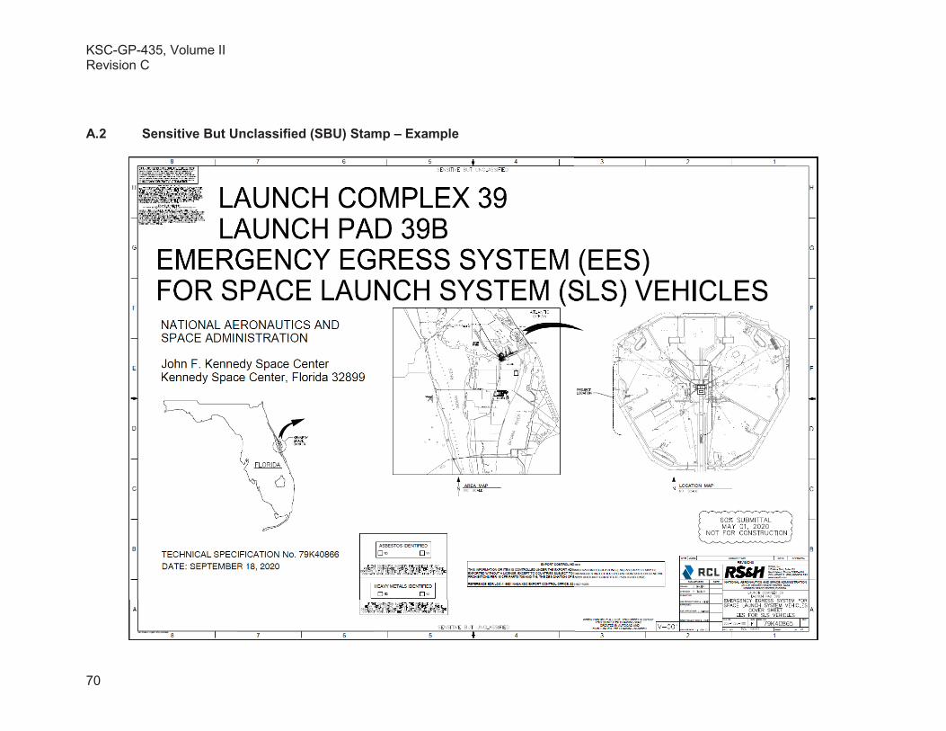
KSC-GP-435, Volume IIRevision C
70
A.2 Sensitive But Unclassified (SBU) Stamp – Example

KSC-GP-435, Volume IIRevision C
71
A.3 Engineering Order, KSC Form 21-34 – Example

KSC-GP-435, Volume IIRevision C
72
A.4 Engineering Order (Continuation Sheet), KSC Form 21-34 – Example

KSC-GP-435, Volume IIRevision C
73
A.5 Drawing Cover Page - Example
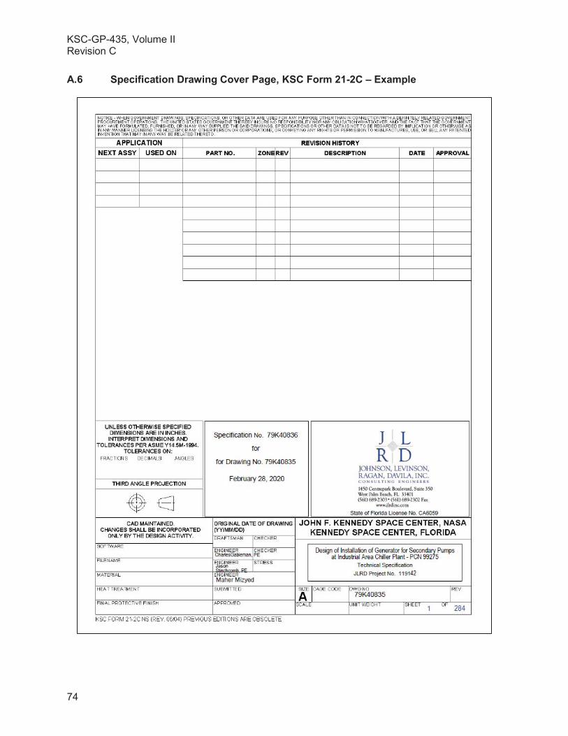
KSC-GP-435, Volume IIRevision C
74
A.6 Specification Drawing Cover Page, KSC Form 21-2C – Example

KSC-GP-435, Volume IIRevision C
75
A.7 Data Manual Cover Page – Example
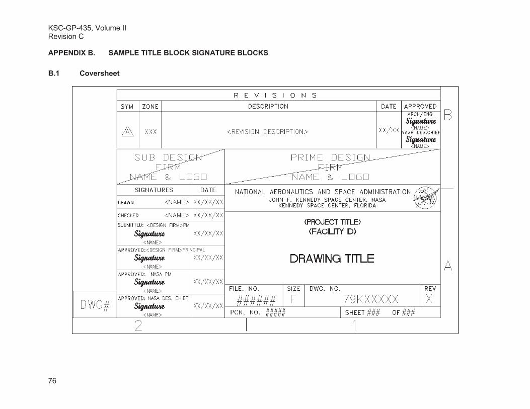
KSC-GP-435, Volume IIRevision C
76
APPENDIX B. SAMPLE TITLE BLOCK SIGNATURE BLOCKS
B.1 Coversheet

KSC-GP-435, Volume IIRevision C
77 of 77
B.2 Discipline Sheet