Embed Size (px)
Citation preview

II 4D-AM3 599 HEAT TRANSFER RETARDATION AT ELEVATED TEMPERATURES 1/2IiPHASE I ANALYSIS OF HE-.(U) UNITED TECHNOLOGIES
RESEARCH CENTER EAST HARTFORD CT C W~ DEANE SEP 83
UNCLASSIFIED UTRC/R83-9562i6-i NW814-82-C-e67i F/G 20/13 N
EhhhhmhhmmhhhlI flfflfll.lflflfl
-y bL-0 - - - . .*-- * * . _n . - V'. - .t
ILB[L
f~l125 I" 1.4 ____
MICROCOPY RESOLUTION TEST CHARTNATIONAL BUREAU OF STANDARDS- 1963-A
.*- .- -* -~ - - * , * - --

HEAT TRANSFER RETARDATION AT ELEVATEDTEMPERATURES
Phase I -Analysis of Heat Transfer RetardationConfigurations and Materials
Annual Technical Report* September 1983
Charles W. Deane
L~. Prepared forThe Office of Naval Research, Arlington, Virginia
Under Contract No. NOOO1 4-82-0-0671
A ~DT C
Thsdocument has been aproved-Ifor Public release and sAe idistribution is unlimited.
83 09 29 020,

UnclassifiedLO SECURITY CLASSIFICATION OF THIS PACE (ftei Dogs Entered)
REPOT DCUMNTATON AGEREAD INSTRUCTIONSREOR DOCUMRNPOTTONUPAGE BEFORE COMPLETING FORM
I.RRT 56216-1 a. GOVT ACCESSION No. S. RECIPIENT'S CATALOG NUMBER
4. TITLE (dnE Subette) S. TYPE OF REPORT 6 PERIOD COVEREDHeat Transfer Retardation at Elevated Tempera- Annual Technical Reporttures (Phase I - Analysis of Heat Transfer Aug. 15, 1982 - Aug. 14, 1983Retardation Configurations and Materials) S. PERJFORMING ORG. REPORT NUMBER
UTRC/R83-956216-l7 . AUTHOR(s) -.CONTRACT OR GRANT MUMBER(s)
Charles W. Deane, Principal Investigator N00014-82-C-0671
9. PERFORMING ORGANIZATIONd NAME AND ADDRESS 10. PROGRAM ELEMENT. PROJECT. TASKProM ff~hINMR " 31,M~United Technologies Research Center Pro Gct: RRO 4-0r
* .Silver Lane Task Area: RRO 24-03-02East Hartford, CT 06108 Work Unit: NR 097-457
11. CQtROLLING OFFICE NAMEF AND ADDRESS 12. REPORT DATEOffVice of Naval Research September 1983800 North Quincy Street 13. NUMBER OF PAGES
Arlington, VA 22217IC. MONITORING AGENCY NAME A ADDRESS(iI diffeent from Controlling OfiSce) 1S. SECURITY CLASS. (of this report)
UnclassifiedIS. ECLASSIFICATiON DOWNGRADING
SCH4EDULE
* . I4. DISTRIBUTION STATEMENT (of this Report)
Approved for public release; distribution unlimited
17. DISTRIBUTION STATEMENT (of the abstract entered In Stock 20. it different Inro Report)
Same as block 16
I$. SUPPLEMENTARY NOTES
19. KEY WORDS (Continue on, reverse side fl necseav Mmd Odentfly by bleck .,inbse)
Heat Transfer RetardationHigh-Temperature InsulationHot-Gas Duct ing
( 2* ASTIIACT (CM1flwe 01% rewers" 41141 It 10000,08" 411d Identity by block amber)
~e heat transfer retardation characteristics at high temperatures ofselected combinations of configurations and their materials of construction
were analyzed, and lightweight retardation configurations have been identifiefor hot-gas applications with hot-side temperatures of 3000 F. The scope of
the investigation was to use available materials and passive retardation tech-niques. Candidate structural configurations with promising heat transfer
(Cont'd)
DD 1473 EDITION OF I NOV 4 1 IOBSOLETE UnclassifiedS/N 0 102- LF- 014- 6601 SECURITY CLASSIFICATION OF THIS PAGE (Manm De18 Entered,'
. Unclassified
" NUS1eTV 96IAMtIPICATO or TIII PAOI9 01011 am ao* ,etardation characteristics were defined, candidate materials were identified,
and combinations of these configruation types and their materials of construc-tion were selected for analysis.
A heat transfer model was formulated for the analyses of the retardationconfigurations selected for hot-gas applications and was used to estimate theretardation characteristics in terms of an overall thermal resistance and unitweight. Multi-layer configurations were selected with the thin outer layer ofceramic foam providing a hard and relatively smooth surface for flow path andstructure, and the inner fibrous layer(s) providing the bulk of the thermalresistance. The overall lightweight combination consists of All-Alumina foanand Dynaquartz (silica) fibrous insulation, because each material has thelowest value of the insulation performance factor in its category of material-s
S/ H 0102. L F. 014. 6601 U n c l a s s i f i e d
SECURITY C LASSIFIlrCATION OFr TNIS PAGIL ften n~ot l Ioed.
* "*
',, ." . 2 2 ; ; ; " .." *. . . . -. ; 2 .- '......,, %,. .'.," .. ,-. ... < ." = . -.-.-. -. ., .- . .. -

R83-956216-1
Heat Transfer Retardation at Elevated TemperaturesPhase I - Analysis of Heat Transfer Retardation
Configurations and Materials
Annual Technical Report
Charles W. Deane-* Principal Investigator
(203) 727-7245
Prepared for:
The Office of Naval Research*' Arlington, Virginia
.4Z Under Contract No. N00014-8-2-C-0671
Mr. M. Keith Ellingsworth, Scientific Officer
September 1983 :* . .-- 4
S II-- -.
o.--
,low.
R83-956216-1
Heat Transfer Retardation at Elevated TemperaturesPhase I -Analysis of Heat Transfer Retardation Configurations
and Materials
TABLE OF CONTENTS
Page
FORE WORD .. ......... ............... .........
SUMMARY. .......... ............... ........ 2
RESULTS AND CONCLUSIONS .... ............... ....... 4
INTRODUCTION. .. .... .............. ........... 6
INTRODUCTION REFERENCES .... ............... ....... 9
PHASE I - ANALYSIS OF HEAT TRANSFER RETARDATIONCONFIGURATIONS AND MATERIALS .. .......... ....... 10
1.1 Crucial Problems and Technology Status. .... ......... 101.2 Definition of Candidate Structural Configurations. ....... 231.3 Physical Properties of Candidate Materials. .... ....... 271.4 Selection of Configuration and Materials Combinations .... 331.5 Analysis of Retardation Characteristics. ............ 391.6 Lightweight Retardation Configurations .. ............ 50
REFERENCES . .. .. .. .. .. .. .. .. .. .. .. .. .. .. .... 53
TABLES
FIGURES
4U

283-956216-1
FOREWORD
*The work described in this Annual Technical Report was performed at theUnited Technologies Research Center (UTRC) under Contract N00014-82-C-0671 en-titled "Study of Heat Transfer Retardation at Elevated Temperatures", for theOffice of Naval Research (ONR). This report summarizes the results obtained for
-Z,: the Phase I - Analysis of Heat Transfer Retardation Configurations and Materialsstudy program. Prior to his departure from UTRC on July 15, 1983, Dr. Simion C.Kuo was the Principal Investigator for this program, and his contributions tothis program are gratefully appreciated.
The contract program was initiated with ONR on August 15, 1982, and the ONR4Scientific Officer for this contract program is Mr. M. Keith Ellingsworth,
Mechanics Division, ONR, Arlington, Virginia. Valuable guidance and commentsZreceived from Mr. Ellingsworth are gratefully acknowledged.
£.
:N
-..-. **.- ... . . * . ** . . . . .

-. 7-7 :77. 17'17"-.77
R83-956216-1
Heat Transfer Retardation at Elevated Temperatures
Phase I - Analysis of Heat Transfer Retardation Configurations_' and Materials
SUMMARY
The objectives of the work presented in this report were to analyze the
retardation characteristics of selected combinations of configurations and their
materials of construction, and then to identify lightweight retardation configur-ations. As a basis for the analysis, the crucial problems and technology status
of heat transfer retardation at high temperatures were assessed. Candidatestructural configurations with promising heat transfer- retardation characteris-tics were defined, candidate materials for retardation applications were identi-
fied, and combinations of these configuration types and their materials of
construction were selected for analysis. A model of heat transfer was formulatedfor the analyses of the retardation configurations selected for hot-gas applica-
tions and was used to estimate the retardation characteristics and to identify
lightweight retardation configurations.
The technology status of heat transfer retardation at high temperatures was
assessed by reviewing previous investigations, both analytical and experimental,
and the physical geometries used and their materials of construction were sum-
marized in order to identify the crucial problems encountered by previous inves-
tigations. Candidate structural configurations with promising heat transferretardation characteristics and relatively low weight were defined for detailedanalysis. The physical properties of materials of construction for these config-
urations were examined for application to heat transfer retardation in hot-gasapplications and also passive laser countermeasures applications. Then combina-
tions of configuration types and their materials of construction were selected
for analysis of their overall retardation characteristics relative to their
weight characteristics, and possible operating limits of these combinations were
identified for selected applications.
Finally, a model of heat transfer for the configurations and materials
selected for hot-gas applications was formulated and has been used to estimate
_S 2

R83-956216-1
the heat transfer retardation characteristics in terms of an overall thermal
resistance through the configuration. The unit weight of the overall configura-
tion was also analyzed for use in identifying lightweight combinations of config-
uration types and their materials of construction. The limitations in the model
caused by the simplifying assumptions were described. Based on performance
analyses of the selected configurations using this model, lightweight retardation
configurations have been identified for hot-gas applications, and the effects of
the geometric parameters of each configuration upon heat transfer retardation
have been estimated.
This study program was conducted by the Thermal Engineering Group at UTRC
under Contract N00014-82-C-0671 from the Office of Naval Research, Mechanics
,Division, Arlington, Virginia.
3
re 7

R83-956216-1
RESULTS AND CONCLUSIONS
1. The crucial problems of heat transfer retardation at high temperaturescan generally be grouped into three areas: the temperature capability ofavailable materials, the heat transfer and weight characteristics, andstress and attachment problems.
2. Candidate structural configurations of retardation materials for hot-gasapplications can be grouped into five categories: fibrous, ceramic foam,ceramic composite, radiation/layered, and powder materials.
3. Few insulating materials are available for applications at 3000 F andhigher, as problems with shrinkage, chemical reactions, and/or meltingdrastically reduce the field of candidate materials as the expected temper-ature level increases.
4. The available candidate materials with the advantageously lowest valuesof the insulating performance factor (pk) are: All-Alumina ceramic foamwhich has a maximum operating temperature that approaches 3000 F; andDynaquartz (silica) fibrous insulation which has a maximum operatingtemperature of 2700 F. Ceramic composites offer excellent mechanical pro-perties at high temperatures but are currently limited to 1800 F because ofoxidation problems.
5. The rationale of using multi-layer configurations to provide heat trans-fer retardation for hot-gas applications is that: (1) a thin outer layerof ceramic foam provides a hard and relatively smooth surface for flow pathand structure, and (2) the inner fibrous layer(s) provide the bulk of theheat transfer resistance because of the lower effective thermal conduc-tivity.
6. A ulti-layer approach is also preferred for passive laser countermea-sures applications. The outer layer is reflective, to reflect the electro-magnetic energy of the beam before it is converted to thermal energy; themiddle layer is an ablative material (possibly incorporating capsules ofgas that would absorb the beam's energy, to provide protection duringattack); while the inner layer(s) of thermal insulation would protect theunderlying structure and/or electronics against the thermal wave induced bythe high-intensity beam of short duration.
4

283-956216-1
7. The analyses of heat transfer retardation characteristics for hot-gasapplications show that, at equal values of the overall thermal resistance(R-factor), the overall lightweight combination consists of All-Alu'nafoam and Dynaquartz fibrous insulation because each material has the lowestvalue of the insulation performance factor in its category of materials.
8. If the total thickness of insulation is limited to one inch, with a 3000F hot-side and a 1200 F cold-side temperature, the expected heat loss isapproximately 2900 BTU/hr-ft2 and the weight per unit face area is approx-imately 0.6 lbm/ft2 for the lightweight combination of All-Alumina foamwith Dynaquartz fibrous material.
-4
3 5
.~ *~%....
if if . -. . . .. .

R83-956216-1
INTRODUCTION
Advances in high-temperature heat transfer retardation have been made inrecent years in response to the development trends of various propulsion devices
and heat transfer equipment towards higher temperatures in order to obtainimproved performance with minimum size and weight. For example, one method of
.!4 increasing the efficiency of a gas turbine engine is to increase the combustion
gas temperature to the maximum temperature limits of the turbine and nozzle
-. structure. Projections for growth versions of curient comm-ercial aircraftengines indicate that the turbine inlet temperature will approach 2800 F, while
. future engine generations for the later 1980's will require turbine inlet temper-
atures of 3200 F. Gas temperatures in gas turbine engines are already higherthan the maximum temperature capabilities of conventional superalloys because ofheat-resistant coatings and because compressor bleed air is used to cool the hot
components, but the loss of this high-pressure air from the cycle results in anengine performance penalty. Further, the components that do require this cooling
-. are more complex than similar but uncooled parts and are therefore more expensiveto fabricate and maintain than parts that do not require cooling.
When protected from rapid oxidation by an attrition-resistant coating, car-
bon-carbon composites have excellent mechanical properties at tetmperatures of up
to 5000 F. Otherwise, without the coating, carbon rapidly oxidizes and erodes attemperatures above 700 F. Carbon-carbon composites arA being cofisidered (Ref. 1)
for high-temperature components such as augmentor liners, nozzleb, and tailconesin advanced engine technologies. Carbon-carbon composites have also been
assessed (Ref. 2) for limited-life gas turbine engineswiCh the conclusion thaethe use of these composites is not a question of payoff but ratheVy a question of
achieving the necessary levels of material properties and oxidation protection.
The design philosophy of using carbon-carbon composites with their relatively
high thermal conductivity is to allow the components to see the high temperaturesof the environment.
In contrast, the design philosophy of using a heat transfer retardation
configuration made, in part, of ceramic is to minimize the heat being transferredto the component being protected. Ceramic materials have the advantage over
carbon-carbon composites of offering insulation capabilities. Ceramics have been
explored (Ref. 3) with increasing interest during the last decade for use inturbine engines to provide both insulating qualities and high-temperature capa-bilities. Reusable heat shields using ceramic materials instead of ablating
techniques have been under investigation (Refs. 4 and 5) for space shuttleorbiters. Some of these concepts use fibrous ceramic materials for insulation(Refs. 6 and 7), and a closed-pore insulation (Ref. 8) made from low-cost fly ash(which is a product of coal combustion) has also received attention. The use ofthermal coatings - a thin layer of ceramic, typically 0.015 in. thick - as
-e
6
S* .=
R83-956216-1
applied to gas turbine airfoils (Ref. 9) has the potential for protecting the gasturbine components from the erosive and corrosive environment of hot combustiongases, thereby permitting the use of less refined and cheaper fuels in a gas
turbine/steam turbine combined cycle. Plasma-sprayed ceramic coatings, typically0.12 in. thick, are also being developed (Refs. 10, 11 and 12) by UnitedTechnologies/Pratt and Whitney Aircraft under NASA contract for use as abradable
* blade-tip seals in high-pressure turbine applications.
The previous work on heat transfer retardation at high temperatures (over
2000 F) has made important advances, but problems still exist and require addi-
tional analytical and experimental research. First, the thin thermal barriercoatings that are being developed for use in gas turbines do not provide the highlevels of heat transfer retardation that are necessary for other applications.
A second problem occurs with the thicker configurations that weigh too muchVfor the level of heat transfer retardation that is provided. Promising configur-
ations must be identified and then analyzed to select lightweight configurations,which must then be tested to confirm the thermal analyses.
The third shortcoming of the previous work is that only a limited amount of
analytical work has been done to sort out the various options available in termsof configurations and the materials of construction for each of the possiblelayers in a multi-layer heat transfer retardation configuration. The overall
heat transfer retardation characteristics of a multi-layer construction can bedescribed in terms of a thermal resistance per unit thickness for comparison withother retardation configurations.
The objectives of the Phase I - Analysis of Heat Transfer Configurations andMaterials study program described herein were to analyze the heat transfer retar-dation characteristics of selected combinations of configurations and their mater-
ials of construction, and then to identify preferred lightweight combinations.
The scope of the investigation is to employ available materials in the selectedcombinations, to examine the heat transfer and weight characteristics of selectedcombinations, and to utilize passive retardation techniques. The main applica-
tion of interest here is for hot-gas flows, such as hot sections in gas turbinesor hot-gas ductifig. These are relatively steady-state applications, with thehot-side temperature of interest above 3000 F, and the cold-side temperature in
the range of 1200 F to 1800 F. A brief look was also taken at heat transfer
retardation for passive laser countermeasures applications, which involve rapid
heat transients caused by high-intensity beams of short duration. Sacrificialmaterial loss (ablation) is the approach to absorb this energy, with an insula-
ting layer to protect the underlying structure and/or electronics from the subse-quent thermal wave.
7

R83-956216-1
The results of this Phase I study program are presented in this report. Thecrucial problems and technology status of heat transfer retardation at hightemperatures were assessed and summarized in Task I.1. Candidate structuralconfigurations with promising heat transfer retardation characteristics were
defined in Task 1.2, candidate materials for retardation applications were iden-tified in Task 1.3, and combinations of these configuration types and theirmaterials of construction were selected in Task 1.4 for analysis. A model ofheat transfer was formulated in Task 1.5 for the analyses of the retardationconfigurations selected for hot-gas applications and was used to estimate theheat transfer retardation characteristics in terms of an o'.erall thermal resis-tance, and lightweight retardation configurations were identified in Task 1.6based on these analyses.
8

R83-956216-1
INTRODUCTION REFERENCES
1. Parkola, S.: Advanced Technology Engine Studies (ATES) - Task II FinalReport. United Technologies/Pratt & Whitney Aircraft Report No. FR-14592 onDepartment of the Navy Contract No. N00019-80-C-0025, December 1981.
2. Cruzen, G. S., L. J. Davis, and J. B. Carlton: Advanced Gas TurbineCarbon/Carbon Components Feasibility Assessment. Report No. AFWAL-TR-80-
4036, April 1980.
3. Burte, H. M., ed.: Ceramics for Turbine Engine Applications. AGARD Confer-
ence Proceedings, No. 276 1979.
4. Giezma, C. J., W. B. Hunter, et al.: Final Report on Structural Heat Shield
for Reentry and Hypersonic Lift Vehicles - High Temperature Composite Struc-ture. Report No. ML-TDR-64-267, Part I, Vols. 1 and 2, 1965.
5. Chapman, A. J.: Evaluation of Reusable Surface Insulation for Space Shuttle 9Over a Range of Heat-Transfer Rate and Surface Temperature. NASA TM X-2823,
1973.
6. Rolinski, E. J., et al: Development of High-Temperature Insulation Systems.AIAA Paper No. 66-43, 1966.
7. Kummer, D. L. and G. B. Bilow: Refractory Materials and Insulation. AIAAPaper No. 68-1128, 1968.
8. Tobin, A., et al.: Development of a Closed Pore Insulation Material. NASA
Report CR-2254, 1973.
9. Nainiger, J. J.: Effect of Thermal Barrier Coatings on The Performance of
Steam- and Water-Cooled Gas Turbine-Steam Turbine Combined Cycle Systems.NASA Report TM-79057, 1968.
10. Shiembob, L. T.: Development of a Plasma Sprayed Ceramic Gas Path Seal forHigh Pressure Turbine Applications. NASA Report CR-135387, 1977.
11. Shiembob, L. T.: Development of a Plasma Sprayed Ceramic Gas Path Seal for
High-Pressure Turbine Application. NASA Report CR-135387, 1978.
12. Bhiembob L. T.: Development of Improved High Pressure Turbine Outer GasPath Seal Components. NASA Report CR-1519801, 1980.
pi
• - |.
a -
. . .]
- R83-956216-1
PHASE I ANALYSIS OF HEAT TRANSFER RETARDATION
CONFIGURATIONS AND MATERIALS
The object of this study program is to analyze the retardation characteris-tics of selected combinations of configurations and their materials of construc-tion and then to identify lightweight retardation configurations. This study
consists of six tasks: I.1) Crucial Problems and Technology Status; 1.2) Defini-
*. tion of Candidate Structural Configurations; 1.3) Physical Properties of Candi-date Materials; 1.4) Selection of Configuration and Materials Combinations; 1.5)
. Analysis of Retardation Characteristics; and 1.6) Lightweight Retardation Config-- urations. The results obtained in each of these six tasks are presented in the
following sections.
N 1.1 Crucial Problems and Technology Status
Progress in the fields of space exploration and reentry applications has
sparked interest in the development of high-temperature thermal retardation
systems. Many aerospace applications involve exposure to a hyperthermal envir-onment where severe heating and stress loading conditions occur. Hence, a high-
temperature thermal retardation system may be required to protect the load carry-
ing structure. Figure 1.1 shows a typical example of a multi-layer retardationdevice that was designed as the heat shield for a reentry vehicle.
Thermal protection systems can generally be categorized as either absorptive
or radiative, depending upon the primary method by which the incident energy isdissipated. Included among the absorptive types of thermal retardation systemsare systems that involve ablation, heat sinks, convection cooling, and film andtranspiration cooling. There are several forms in which the energy can arrive at
the retardation surface from its source: forced convection, thermal radiation,and electromagnetic radiation (laser). The design of a thermal retardation
system involves the interaction of environmental, material, and application
factors, which must all be considered in the evolution of the design of . hermalretardation system. The form in which the energy arrives can affect the surfacedesign of the retardation device. To minimize forced convection heat transfer, asmooth surface to minimize the heat transfer coefficient and area will be
preferred. Electromagnetic energy can be reflected by the surface before beingconverted into thermal energy. To lose heat by radiation from the surface, acolder heat sink elsewhere would be necessary.
Because of the many possible applications and the vast array of design
requirements which are specific to each application, many different approacheshave received attention. Hence, to lay the groundwork for the analyses of heat
transfer retardation characteristics to be done in this study program, crucial
10
10.

R83-956216-1
$2 problems and the technology status of heat transfer retardation were examined toidentify the physical geometries and the materials of construction used in pre-vious investigations and their limitations. Previous analyses of retardationcharacteristics were identifed, and previous experimental work was summarized interms of data, experimental conditions, and intended applications.
1.1.1 Physical Geometries and Materials of Construction
Combinations of physical geometries and materials of construction thatprevious investigators have examined are discussed in this section. The physicalgeometries include honeycomb structures, fibrous blanket configurations, moldedblock construction, flakes, and various combinations of these geometries to formthe overall thermal retardation device. In fact, most thermal retardation sys-tems consist of a combination of geometries and materials tailored to be compati-ble with the temperature gradient.
Honeycomb structures have been examined by several investigators. Giemza etal. (Ref. 1) developed a high-temperature composite heat shield using foamedceramics for reentry and hypersonic lift vehicles. The thermantic structure thatthey developed combines the refractoriness of oxides, the insulation qualities ofceramic foam, and the honeycomb reinforcement of the ceramic foam to assure theintegrity of the heat shield with the back-up structure. The risk of
5 catastrophic failure, which can occur in monolithic structures under thermalstress, is substantially minimized by the individual ceramic cell arrangement.For the high surface temperatures associated with reentry vehicles, most of theincident heat is rejected by radiation. Control of the ceramic porosity is animportant factor, because an increase in porosity will result in a reduction ofdensity and thermal conductivity but correspondingly lower strength character-istics. The main limitation appears to be that the metallic honeycomb core wouldsubstantially reduce the thermal resistance of its layer, because the heat wouldbe preferentially conducted through the metal core and in that manner bypass thethermal resistance of the ceramic foam.
Scanlon (Ref. 2) proposed folded metal inserts to increase the thermalresistance of an otherwise empty honeycomb panel. The thin cell walls of ametallic honeycomb structure provide quite high thermal resistance to conduction,but when the temperature of the hot side of the panel is above 1000 F, thenradiation from the hot side of the panel to the cold side can become the princi-pal mode of heat transfer. Thin folded metallic inserts are attached by meanssuch as brazing, welding, or diffusion bonding to the inside of each honeycombcell and shield the cold side from the thermal radiation from the hot side. Themain limitation with this configuration would appear to be the problem of insur-ing that the numerous small inserts are properly placed and attached to the wallof each of the honeycomb cells.
11':
-7-3 -T 7 -7 P
R83-956216-1
Fibrous-type heat transfer retardation devices have also been examined.Rolinski et al. (Ref. 3) evaluated fibrous insulations for use in thermal retar-dation systems for reusable reentry and hypersonic cruise vehicles. Thermalconductivities of promising fibrous insulations were measured. Based on testresults for low-density fibrous insulations above 2000 F, gas conduction andradiation through the insulation may account for up to 30 percent and 90 percent,respectively, of the total heat transfer through the insulation, while solidconduction heat transfer is of limited importance. In other words, if severalmodes of heat transfer are operating in series, the heat will be transferredthrough the low-resistance paths and will bypass the high-resistance path (ofpure conduction through the fibers, in this instance). But the principal short-coming of fibrous materials is their mechanical instability. Although shrinkagemay be reduced by controlled fabrication procedures and pretreatment at hightemperatures, compressive strength and resistance to sonic fatigue are onlymarginal. Sintering at temperatures above the pretreatment temperature may alsolimit the use of fibrous insulations. Very-low-density compacts of ceramicfibers (Ref. 4) are competitive with low-density ablators and are potentiallyreusable. Many conventional ceramic fiber insulations are not dimensionallystable at temperatures above 2200 F, or will not withstand noise and vibration tobe reusable for multiple flights of reentry vehicles if heated above this temper-ature. But fibers such as zirconia and sapphire do show promise for applicationsabove 2500 F.
An investigation was conducted by Chapman (Ref. 5) to evaluate reusablesurface insulation materials for use as heat shields for the space shuttleorbiter. These materials are formed by rigidizing low-density ceramic fibers andapplying a dense high-emittance coating. A silica-base material experienced onlyminimal degradation during repeated tests which included conditions twice assevere as predicted shuttle entry and withstood cumulative exposures three timeslonger than the best mullite material. Mullite-base materials cracked and exper-ienced incipient melting at conditions within the range predicted for shuttleentry but neither silica nor mullite materials consistently survived the testseries with unbroken waterproof surfaces.
Martynenko et al (Ref. 6) used high-alumina wool for insulation tubes (withinside diameters of 4.3 in. and 5.7 in.) to be used as ducts for molten non-ferrous metals at temperatures of up to 2000 F. The tubes were manufactured fromthe ceramic fibers by in-vacuo forming and by the layer-wise deposition ofceramic-fiber paper with a bonding substance.
Molded block configurations have been studied by many investigators andoffer the feature of modularity. Generally, molded blocks are produced by plac-ing the ingredients in a mold and then firing the mixture in a furnace. For use
as a high-temperature heat shield on a space shuttle, Tobin et al. (Refs. 7 and8) have developed a closed-pore ceramic foam insulation made with a low-cost raw
12
P 'm.v o-..................... . . . .

R83-956216-1
material (fly ash, obtained from the combustion of coal) which has negligiblewater absorption because of the noninterconnecting network of cells and which hasa high emittance for radiation heat transfer. Basically, a face sheet of closed-pore foam insulation (up to 0.5 in. thick) is supported by a lightweight metallic
honeycomb, with the cells of the honeycomb being filled with lightweight refrac-tory fibers (such as microquartz). The ductile honeycomb core tends to isolatethe brittle closed-pore foam insulation from the rigid backside metallic struc-ture which is in turn attached to the primary structure. The cenospheres (whichare spherical, hollow glass particles) are heated in a mold in air or any inertatmosphere at firing temperatures in the range of between 2500 to 3000 F, and the
cenospheres then shrink together to form a closed-pore ceramic foam. The two
problems with the closed-pore foam insulation are a relatively high density andthe tendency to develop hairline stress cracks in pieces with the thicknessnecessary to provide sufficient heat retardation. Stated another way, thethermal conductivity of this foam insulation is too high, and the thickness of
the foam insulation must therefore be increased to provide sufficient heat trans-
fer retardation.
Another high-temperature insulating material is carbonized granulated cork(Ref. 9) that has been molded to the desired shape. The cork particles are
placed in a mold and are then heated at a temperature of about 570 F. This tem-perature level effects the flow of the lignin (naturally found in cork) whichacts as a binder. Then the bound cork granules are carbonized in an inert atmos-phere such as argon or helium. The carbonized cork material may then be graph-
tized, at a suitable temperature of about 5400 F. One application for thisgraphite cork material is to insulate heat sources in radio-isotopic thermo-electric generators for space applications, and an important feature of thismaterial is that its thermal conductivity does not increase with temperature, in
contrast to the temperature dependence of carbon foam and fibrous carbon.
Graphite flakes and fibers have also been developed for high-temperatureheat transfer retardation devices. Graphite flakes (Ref. 10) are placed in
fibrous thermal insulation to increase the opacity of the composite insulation to' radiation. Thin graphite flakes are oriented in the fibrous insulation with the
maximum dimension of each flake being approximately perpendicular to the expecteddirection of heat flow through the composite. A mixture of water and starchparticulates is used as the binder to secure the flakes to the fibers. The
resulting slurry of fibers, graphite flakes and the water and starch is vacuumformed into the desired configuration. The slurry is then heated to gelatinizethe starch, and then the dried mixture is heated further so that the starch isconverted to carbon which thereby joins the fibers together. Composite insula-tion fabricated by this approach was tested at temperatures above 3800 F in a
vacuum.
13 .. .-

R83-956216-1
In another approach to decreasing heat transfer by radiation, Deschamps andBernier (Ref. 11) coat the insulation, either a fiber base or spheres, with a
thin layer of highly heat-reflective, low emissivity material. In the case ofspheres in a vacuum atmosphere, the point contact between the spheres results inpoor heat transfer by conduction, and the vacuum conditions substantially elimin-ate convection heat transfer. Then, if the spheres are coated with reflectivematerial, the radiation mode of heat transfer is also substantially eliminated.A fibrous base material can also be used instead of the spheres. For example,Min-K can be used with the fibers coated with a thin layer of highly heat reflec-tive, low emissivity material, preferably a metal which can be applied by avacuum sputtering technique to deposit a film on each fiber in a mass of fibers.
Asbury and Googin (Ref. 12) have developed an inorganic thermal insulationthat is made from minute particles of silicon oxide mixed with inorganic fibers,an organic wetting agent, and octanoic acid that will act as a binder for thesilicon oxide particles. The mixture is heated, ground, pressed into a mold withthe desired configuration, and then lightly sintered in an inert atmosphere. Thethermal conductivity of the resulting material was measured at temperatures ashigh as 2700 F.
Vogan and Trumball (Ref. 13) have investigated metal-ceramic composites witha magnesia foam backing for use on nose caps and leading edges of re-entry vehi-cles. Alumina with metal honeycomb reinforcements was evaluated, and thepreferred system is a partially crushed honeycomb structure in which the honey-comb is bonded to the desired backing material and partially filled with afibrous insulating material. The rest of the structure is filled with analumina-binder mix which is pressed into place and cured at 800 F. Chemically-bonded zirconia has also been examined and found to work very well as theceramic. Superalloy honeycomb materials were found to be satisfactory fortemperatures of up to 3000 F, even though some melting can occur at the surface.The ceramic retention is considerably improved by partially crushing the honey-comb. This crushing is accomplished without buckling the honeycomb by fitting itwith a matrix material that is removed after the honeycomb has been compressed.The metal honeycomb reinforcements primarily serve to control thermal shock andto limit subsequent crack growth. Ceramic foams were developed as an insulatingbacking to the metal-ceramic honeycomb structures, in order to protect the sup-port structure from heat. The best zirconia foams were produced by a chemicalblowing process, where the pores in the ceramic are produced by a gas generatedthrough a chemical reaction between zirconium metal and phosphoric acid. Mechan-ically wipped foams were also investigated, because satisfactory chemically blownmagnesia foams could not be developed within their time schedule. Three methodsof reinforcing the ceramic bodies were investigated: the metal honeycomb dis-cussed above, wires, and flame-sprayed backings. Ceramic samples containingmagnesia and wire reinforcements were prepared by pressing them at 12,000 psi andthen sintering them in an argon atmosphere for 20 hrs at 2200 F. The samples
14
R83-956216-1
containing tantalum and tungsten wires cracked during sintering, but the sampleswith platinum, molybdenum or Rene 41 did not crack. Cracking in the tantalumsample was attributed to differential thermal expansion between the two mater-ials. Flame-sprayed backings were also investigated because the resistance tospalling shown by the magnesia body indicated that metal reinforcement might notbe needed throughout the ceramic phase. Three samples were tested, but cracksoccurred in one and delamination of the flame-sprayed surface occurred with theother two samples.
An amorphous carbon-layered composite has been developed by Allen and Lysher(Ref. 14). This thermal insulation consists of separate layers of particulatematerial selected from materials with low thermal conductivity above 1800 F andfrom materials with low thermal conductivity below 1800 F. These layers areseparated by one or more layers of metal sheets, which act as radiation shieldsand internal structural support for the particulate layers and as barriers totransverse fracturing. The insulation layers are composed of unbonded particleswhich have a lower thermal conductivity than materials with particles that arephysically or chemically bonded together. For example, in a three-layer compos-ite, the outer layer could be amorphous carbon black which has low thermalconductivity above 1800 F. The middle layer of metal could be a sheet of tanta-lum foil, while the inside layer could be zirconia which has low thermal conduc-tivity below 1800 F.
Thin thermal barrier coatings have been investigated for the protection ofcooled rocket nozzles and gas turbine components (Ref. 15). A thermal barriercoating is a thin layer of ceramic applied, for example, to the hot-sectioncomponents of a gas turbine. The basic concept of heat barrier coatings is thatthe thermal resistance of the coating reduces the heat flux through the chamberwall (in the instance of a rocket engine), thereby keeping the metal surfacetemperature below the acceptable limits. The selection of the optimum thermal
*resistance is generally a compromise between the coating thickness and therequired thermal protection. Thick coatings are to be avoided for three reasons:economics, convenience in applying the coating, and minimization of thermalshock. Typically, coating thicknesses of 0.015 in. are used, but coatings thisthin can provide only modest levels of heat transfer retardation because thethermal conductivity of ceramic metals such as yttria-stabilized zirconia arerelatively high.
Research at United Technologies/Pratt and Whitney Division (Refs. 16, 17 and18) has investigated plasma-sprayed yttria-stabilized zirconia (ceramic) for usein gas turbine blade-tip seals for operation at temperatures up to 2400 F. These
seals have a ceramic thickness of 0.15 in. The weight fraction of the zirconiaspray powder can be varied to tailor the thermal conductivity of a materialdesigned for use at a given maximum temperature. The blade-tip seals have a dual
15

R83-956216-1.oI.
function of not only providing a gas-path seal in the turbine but also providingthermal protection for the support structure.
Pechman and Beasley (Ref. 19) describe ceramic glaze coatings which arenonporous and impervious to moisture and which can withstand repeated exposuresto alternating high and low temperatures. The coatings were applied to fibroussilica insulation which has a low coefficient of thermal expansion and a lowemissivity. If a suitable ceramic glaze coating is not used, fibrous insulationscan readily absorb moisture.
An extensive investigation of thermal protection system was conducted by'N Hurwicz and Mascola (Ref. 20) for use on the exterior of glide reentry vehicles.
Their study concentrated on radiation and radiation/ablation systems for thermalprotection. Extensive performance studies were conducted on the weight of radia-tion shields, including the effect of backface cooling, as a function of ideal-ized material properties (density, thermal conductivity, and specific heat),for typical reentry glide vehicle heating rates and stagnation enthalpy. Simi-larly, extensive performance studies were conducted for radiation/ablationshields as a function of idealized material properties, including the ablationtemperature and the heat of ablation. Models of radiation shields were made, inthe form of flat plates, of pyrolytic graphite and also of molybdenum with thefront face coated by a chromium diffusion process for oxidation protection.Radiation/ablation models in the shape of spherical-radius blunt-nosed cylinderswere made of four different materials: X4000 and X5000 (experimental materialsunder development at the time by Avco); Teflon; and a zirconia matrix filled withpolymethylmethacrylate.
Many candidate ablation materials have been studied for various applica-
tions, depending upon the heat rates and their duration. Weinberg (Ref. 21)developed an ablating material which consists of a char-forming polymer and amixture of a solid noble-gas fluoride and sulfur. The heat generated duringreentry by friction between the earth's atmosphere and the heat shield causes thesulfur and the fluoride to react thereby forming gases which are discharged into
F the aerodynamic flow field of the spacecraft. These gases act as a quenchingagent that protects the spacecraft from the heat generated during reentry. The
* ablating material is formed in a mold of the desired shape and is then cured inan oven at approximately 300 F.
Three classes of materials have generally been found to be suitable forablative thermal protection systems on reentry vehicles: refractories andceramics, plastics, and composites. Graphite systems have been examined forreentry vehicles because of their relatively low ablation rates, which result inlow levels of material loss and shape change in areas subject to high heatingrates such as small-radius leading edges and ballistic missile nose tips. Graph-ite sublimes at temperatures as high as 6500 F and absorbs or rejects the heat
16
R83-956216-1
through the combined mechanisms of radiation, oxidation, sublimation, and sensi-ble heating. Pyrolytic graphite, formed by the deposition of graphite layers andhence very anisotropic, has a very low thermal conductivity in the directionnormal to the deposition plane. The major drawbacks to using graphite are itsbrittleness and low resistance to thermal stress, which mean that thick piecescan not be used. Also, delamination of pyrolytic graphite can occur at hightemperature and high thermal stresses, and pyrolytic graphite is difficult andexpensive to manufacture.
Ceramic-based ablators have problems with thermal stress failures, but thisproblem can be lessened by placing the ceramic in a metallic honeycomb. Resin-impregnated porous ceramics (Ref. 22) have better ablation characteristicsbecause the resin component increases the composite strength and the thermalshock resistance. Further the thermal conductivity is reduced and high environ-mental temperatures can be handled without exceeding the melting or decompositiontemperature of the ceramic. The possible porous ceramics include silica, zir-conia, alumina, magnesia, thoria, carbides, borides and silicides. Candidateresin impregnants include the phenolics, epoxies, acrylics, and polystrenes.Metal-base ablators (Ref. 23) have also been studied. A porous refractory skele-ton, tungsten for example, is filled with a metallic infiltrant, such as copperor silver, that has a lover melting point.
Plastic-base ablators, such as teflon for low-temperature applications, arewidely used because of their high heat shielding capability and low thermal con-ductivity, but their disadvantages are high erosion rates when exposed to highgasdynamic shear forces and their inability to handle very high heat loads. The
mechanisms by which plastic-base ablators handle the heat vary: depolymerizationand vaporization for teflon; pyrolysis and vaporization for phenolics and epoxyresins; and decomposition, melting, and vaporization for nylon-fiber-reinforcedplastic.
Composites, in the form of charring-ablator heat shields, are of greatinterest to designers of thermal protection systems. This type of heat shieldcan be made of a thermosetting resin (such as the phenolics, epoxies, or sili-cones) and a refractory fiber (such as glass, asbestos, graphite, or nylon).When the heat shield is heated, the resin begins to decompose (pyrolzye) andreleases gaseous products, leaving a porous carbonaceous residue. The gaseousproducts diffuse through the porous char to the surface, decomposing further and
. absorbing heat from the char. The gases exit into the boundary layer where theyact as a transpirant. The fibers add strength to the char and thereby reduce itsremoval which could be caused by mechanical shear and/or by spalling. A thickchar, primarily carbonaceous, acts as an insulation barrier and radiates heatfrom the surface, as well as being an efficient ablation material.
17
, . . . ."°° . o -. . I. . . .. .- . ,. . ... • . . •.-. o -. ..
Jv 77 7.077
R83-956216-1
1.1.2 Experimental Data on Heat Transfer Retardation Characteristics
Because the heat transfer retardation characteristics of most suitable mat-
erials have to be determined experimentally, most of the investigators of thematerials discussed in the previous section have run some sort of experiments todetermine these characteristics. These measurements could include density, ther-mal conductivity, specific heat and emissivity, and, for ablation materials,
ablation temperature and heat of ablation.
The type of experiments that have been conducted can be generally divided
into two classes: experiments with a composite heat transfer retardation device,
and experiments on individual materials that have been developed for subsequentincorporation into a heat transfer retardation device.
Experiments with composite heat transfer retardation devices have been runon test sections developed for highly specific applications. Giemza et al. (Ref.
1) conducted extensive experiments to develop a composite reinforced ceramic-foamS. heat shield-sandwich structure for a superorbital reentry environment and temper-
atures in excess of 3000 F for a period of up to one hour. Tobin et al. (Ref. 7)tested a closed-pore insulation material with plasma arc jet tests to simulate
entry heating conditions for external insulation on the space shuttle. An arc-driven supersonic wind tunnel was used by Hurwicz and Mascola (Ref. 20) to test
both radiation models (made of pyrolytic graphite and of molybdenum) and alsoradiation/ablation models (made of Teflon, of zirconia impregnated with polymeth-
ylmethacrylate, and of two experimental materials being developed by Avco at that
time). Martynenko et al. (Ref. 6) tested the high-alumina wool tubing under ac-tual operating conditions of carrying molten bronze alloy at approximately 1800 F.
Erosion-shield tiles made of D-36 Columbium tiles and felt ins,.lation on thecold side were tested by Clawson (Ref. 24) under conditions to simulate the heat
loading of a radiation-cooled hot-structure reentry vehicle. Radiant heat lampswere used to heat the tile surface only, and control was by temperature rather
than heat flux. Temperature-time data was obtained for a thermocouple on the
back side of the columbium tile.
In addition to the experiments described above for composite heat transferretardation devices, other investigators have developed and tested individual
materials that may be suitable for incorporation into composite multi-layered
heat transfer retardation devices. Rolinski et al. (Ref. 3) measure the thermal
conductivity of a number of low-density fibrous insulations for use in reusablereentry and hypersonic cruise vehicles. Chapman (Ref. 5) conducted experiments
to investigate the integrity of rigidized ceramic fibers with a high-emittancecoating at conditions twice as severe as predicted shuttle reentry. Klett (Ref.9) measured the density, thermal conductivity, crush stress, and modulus of elas-ticity for the carbonized granulated cork that he developed. Ardary et al.
18

R83-956216-1
(Ref. 10) measured the density, thermal conductivity, compressive strength, andmodulus of elasticity of the material containing graphite flakes and fibers that
they developed. The thermal conductivity and density of the inorganic thermalinsulation made from silicon oxide particles and inorganic fibers was measured by
Asbury and Googin (Ref. 12). Allen and Lysher (Ref. 14) measured the thermalconductivity of the amorphous carbon-layered composite that they developed.
Extensive tests were conducted by Vogan and Trumball (Ref. 13) in their Idevelopment program for metal-ceramic composite heat transfer retardation mater-ials. Thoria and magnesia bodies were tested for thermal shock resistance using
oxyacetylene and plasma torches. The modulus of rupture, thermal expansion,
relative emittance, foam compressive strength and impact strength were measuredfor the various thoria, magnesia, and zirconia metal-ceramic composites that theyexamined.
The ablation characteristics of many materials suitable for radiation/abla-
tion heat shields have also been measured. For example, Straus (Ref. 22) testedimpregnated alumina, zirconia, and silica foams in an oxyacetylene torch facilityto determine the back-face temperature rise for various heating rates. Further
tests were also done in a high-mass-flow hot-gas facility to measure thestrength, erosion resistance, and thermal shock resistance of impregnated cera-
*mics. Weinberg (Ref. 21) tested the char-forming polymer ablating heat shield*material that he developed, with a high-temperature, high-velocity gas to simu-
late conditions for spacecraft reentry. Maloof (Ref. 23) tested a tungsten-based composite ablation material in an arc-plasma generator. -:
Lt-
1.1.3 Analyses of Retardation Characteristics
Heat transfer analyses have been conducted for a number of heat transfer
retardation devices. Generally, many of these analyses have been computerized
numerical analyses for a specific protection device subjected to the transientheating profile for the reentry vehicle being developed. Clawson (Ref. 24) used
a large digital-computer program for the transient two-dimensional and three-dimensional thermal analyses of insulated panels for a glide reentry vehicle,with the temperature-altitude combinations used in the analyses typical of those
expected.
Extensive parametric system studies were conducted by Hurwicz and Mascola(Ref. 20) for radiation heat shields and radiation-ablation heat shields, both
with and without backface cooling. Specific reentry environments were selected,and the thermophysical properties of idealized materials were varied to see theparametric effect on heat shield performance in terms of required heat shieldweight for the mission. The analytical results were used to aid the design of
the experimental test sections that were subsequently tested.
19
......-..;......... ........... . . _ .." * -*
-" " ". " * ' .
"" ." * . .; - "" "" "" '""
183-956216-1
A digital computer code was developed by Rathjen (Ref. 25) for the analysisof two-dimensional transient heating of hypersonic vehicles. The aerodynamicheating boundary conditions are calculated by the code based on the input flight
trajectory, and the method of solution is a hybrid analytical-numerical tech-nique. This solution method is computationally more efficient than conventionalexplicit finite-difference methods when structures with small time constants are
analyzed over long flight trajectories.
A different approach to heat shield design was taken by Garcia and Fowler(Ref. 26). They investigated optimal entry trajectories for the space shuttle
that minimize the weight of the thermal protection system. Two types of thermalprotection systems were considered: a metallic system, with insulation behindthe metal panel; and also a reusable surface-insulation thermal protection sys-tem. Optimal entry paths were generated using the maximum orbiter nose tempera-
ture as a parameter.
Giemza et al. (Ref. 1) conducted parametric analyses to optimize the struc-
tural honeycomb cell size of their composite heat shield structure. Their studywas mainly concerned with the development of manufacturing processes for thecomposite reinforced ceramic-foam heat shield structure, but stress analyses were
also conducted as a part of the study.
Generally, two types of analyses have been conducted by previous investiga-tors. The first type is an extremely detailed numerical thermal analysis,
usually two-dimensional and sometimes three-dimensional, where the performance ofa specific design is intensively studied for its transient retardation responsefor specific reentry trajectories and/or thermal loadings. This type of analysis
normally requires a computerized code to obtain the detailed numerical results of
temperatures at the numerous nodes as a function of time. The second type ofanalysis is a more generalized heat flow network and does not examine theresponse to specific thermal loads such as a reentry trajectory. Rather, a one-dimensional heat flow network is used to compare various proposed thermal retar-dation devices on the basis of the overall thermal resistance of the composite
geometry. Actually, many heat loads will be applied in a nearly one-dimensionalpattern.
Furthermore, for new materials that have been recently developed, the speci-
fic application may not have been identified with its specific thermal loading,but it is still necessary to compare the heat transfer retardation characteris-tics of the composite retardation device incorporating the new material to other
candidate configurations/composites. Hence, the one-dimensional network analysiscan be very useful for basic comparisons between candidate retardation devices
*. without getting deeply involved in the detailed calculations and the specifics ofthe transient thermal load. Later, for the purposes of detailed designs prepara-tory to fabricating the actual retardation device for a specific application,
..,
20
i i. : .ii.:~ ~ ....,...,/... : . i ,

* R83-956216-1
detailed two- or three-dimensional thermal analyses of the proposed device would
be extremely desirable.
1.1.4 Crucial Problems Related to Heat Transfer Retardation
On the basis of the survey of the literature described above, the followingproblems have been identified as crucial in the development and design of heat
transfer retardation devices for high-temperature applications. Generally thecrucial problems can be grouped into three areas: the temperature capability ofavailable materials, the retardation and weight characteristics, and the stress
and attachment problems.
The purpose of a heat transfer retardation device is to protect equipment
and load-carrying structures from thermal loads which would otherwise compromisethe integrity of the equipment and the structure. Thus the retardation device
must provide thermal protection and also maintain its integrity by not crackingafter exposure to the severe operating environment. The strain in the load-car-rying structure being protected must be compatible with the strain allowable inthe retardation device, and the retardation device must also be able to handle
the thermal strain induced by the environment. Fatigue strength may also be a
factor, depending upon the duration and cyclicality of the combined loading, boththermally indiced and structural contributions. Further, some materials may havepotential spalling problems that must be addressed, depending upon the combina-
tion of environmental characteristics.
One of the most critical factors in the design of a heat transfer retarda-tion device is the match between the thermal expansion of the retardation deviceand that of the adjacent structure if a rigid bond is used. On the other hand,
the use of a flexible bond here would greatly reduce the problems associated withpdifferential thermal expansion, but the availability of flexible bonds that can
handle wide temperature ranges is very limited. These bonding related problemshave resulted in the development of composite configurations where theretardation device also provides the necessary structure.
Another major design factor for thermal retardation devices for reentryvehicles is shape retention, particularly small-radius surfaces such as leading
edges and nose tips where erosion can occur and/or ablation can change the shape.Shape changes, could result in changes in the aerodynamic and/or thermal loading
characteristics.
A third important design factor is the manufacturability of the retardationdevice. The materials of construction must be transformable into the designedshape of the retardation device. The inclusion of the bonding materials mustalso be considered in the design of the retardation device, as these materials
may require a curing process after the composite has been assembled.
21
. . . . . .

R83-956216-1
1.1.5 Passive Laser Countermeasures
When a laser beam impinges upon an opaque target material, the beam isabsorbed in a thin surface layer and heat is developed in this thin layer.Simultaneously heat is conducted into the interior of the material, but heatconduction can not provide a sufficient outlet for the large incident laserenergy fluxes that are likely to be encountered in passive laser countermeasureapplications. At these high energy fluxes, the surface of the target materialwill melt and a fusion interface will propagate into the interior of the mater-ial. The heating rate is determined by the heat flux which can be lower than theoptical flux density at the surface of the target because part of the incidentbeam may be reflected by the surface. The heat flux into the target is equal to(l-R) times the optical flux density of the beam, where R is the reflectance ofthe surface and is a strong function of factors such as the surface finish of thetarget material (including its state of oxidation), the temperature of the targetsurface, and the wavelength of the incident beam.
The power levels relevant to passive laser countermeasures are indicated inFig. 1.2, based on information from Ref. 27. Current ablative technology isjudged to be in the range of 10 to 20 kilojoules/cm 2 , while current militarylaser technology at a distance of 2200 miles is judged to be less than aT .oxi-mately 5 kilojoules/cm 2 . Based on these energy levels then, the anticipatadlaser power levels of interest and the duration of the beam can be inferred. Forlong-distance lasers in the range of 10 kW/cm 2 , the durttva of tt;y* beam islikely to be measured in seconds, at current technoloV ievels. Furthermore, as 2shown in Fig. 1.3, the elapsed time before surface melting of a slab of ATJgraphite commences will be measured in fractions of a second for laser powerlevels greater than 5 kW/cm 2 .
22

R83-956216-1
1.2 Definition of Candidate Structural Configurations "
Candidate structural configurations for heat transfer retardation should beselected to minimize the heat transfer rate in terms of the heat transfer modesoperative at the expected temperature levels. The possible modes of heat trans-
fer through the retardation device would include: radiation through porousstructures; conduction through the solid and also the working gas if the struc-ture is porous; and possibly even natural convection if the cells of the porousstructure are open and large. Candidate structural configurations shouldminimize heat transfer by all relevant modes. Other important considerations
include weight characteristics, maximum operating temperatures includingcognizance of any time-at-temperature limitations, and mechanical strength andthermal shock characteristics. Specifics concerning the effective thermalconductivity, the effective density, and the maximum operating temperatures of
candidate materials will be discussed in Section 1.3 - Physical Properties of
Candidate Materials.
Structural configurations of retardation materials for hot-gas applicationscan be grouped into five general categories, as shown in Table 1.1. These five
categories are: fibrous, ceramic foam, ceramic composite, radiation/layered, and
powder materials.
1.2.1 Fibrous Configurations
Fibrous insulations are a familiar type and generally have the lowest valuesof effective thermal conductivity (k) and effective density (p). The loweffective thermal conductivity can be attributed to the poor thermal contact
between the individual fibers that make up the insulation and that are roughly
aligned in planes perpendicular to the direction of heat transfer. If the pore
size of the insulation is extremely small, then the heat transfer rate bymolecular conduction through the gas phase is very low. The fibers themselvesscatter the radiant energy and thereby limit heat transfer by radiation. The low
effective density can be attributed to the high porosity of the collection offibers that form the overall insulation.
1.2.2 Ceramic Foams
Ceramic foams are essentially ceramic materials into which small voids have
been introduced. Two techniques have been used in the past to produce thesefoams: chemical blowing and mechanical whipping. Chemically blown foams can be
produced by gas generated in a chemical reaction throughout the substance whichstarts as a liquid suspension of ceramic particles. The substance with theentrapped bubbles is then cured to form the hard ceramic foam. Mechanically
* whipped foams are produced by mechanical agitation of a liquid suspension of
23
R83-956216-1
ceramic particles, thereby entrapping air to produce the voids in the ceramic
foam upon curing. Ceramic foams generally have higher values of the effectivethermal conductivity and effective density than those of fibrous insulations.
The conductivity is higher, in part, because of solid conduction through the cellwalls and therefore the absence of internal contact resistance that exists infibrous insulations. However, foamed materials have structural advantages thatthe structure-less fibrous materials do not have.
1.2.3 Ceramic Composites
Glass matrix composites with high-strength fibers have been under
development in recent years for gas-turbine applications. The use of fibers
- exhibiting high strength and stiffness can successfully reinforce low-modulusglass matrices, but limitations on use temperature occur. The more recent devel-
*, opment of high-silica glass matrix composites resulted in higher thermal stabil-
ity, but these higher use temperatures resulted in significantly greaterfabrication problems than those of materials with lower use temperatures, because
*" of the much higher viscosity of the higher temperature glass matrix duringcomposite consolidation. To reduce these fabrication problems, a glass-ceramicwas used as the composite matrix, with the resultant combination of high use __
* temperature and simpler fabrication. Composite densification can occur while the
matrix is maintained in a low viscosity glass state while composite structuraluse can take place after the matrix has been crystallized for thermal stability.Thus far, ceramic composites have been reproducibly fabricated with exceptionalmechanical and thermal properties to temperatures of approximately 1800 F.
• . However, accompanying the excellent mechanical and thermal properties which areuseful for structural purposes, the effective thermal conductivity and density ofceramic composites are relatively high for insulation applications, in partbecause the ceramic composites are solid materials.
1.2.4 Radiation/Layered Configurations
The fourth category of candidate structural configurations is radiation/
layered, where thin layers of metallic foil such as tantalum are wrapped with -.
fibrous layers. The purpose of the metallic foil is to reduce radiation through
the insulation layer, but experimental data (Ref. 28) suggests that the effective
thermal conductivity of the combination at high temperature increases over timebecause of reactions between the foil and the fibrous layer. The deterioratedvalues of the effective thermal conductivity of the combination are higher thanthe values of purely fibrous insulations. If radiation/layered materials were
experimentally developed, then these materials could be advantageously used to
provide efficient insulation. Nevertheless, radiation/layered materials aredifficult to use in real systems that have curved surfaces or small dimen-sions.
.24
•24
. , .. . .. . .. . ._. .. . . . .. . .

g 383-956216-1
1.2.5 Powders
The last category of candidate structural configurations is powders, whichare used in cryogenic applications and medium-temperature applications where thinmetal structures can be used to contain the powders. For high-temperature
applications, several problems arise for the potential use of powders. Metalscan not be used for containment at high temperatures in hot-gas applications, andmost powder materials have undesirable sintering and compaction (or shrinkage)
behavior and also can be typically several times as dense as ceramic foam. Solidconduction is limited in powder materials because of the thermal resistance atthe many contact points, and the fine powder also scatters and attenuates thermal
radiation thereby reducing heat transfer by this mode through the insulation.
1.2.6 Suary of Candidate Structural Configurations
Generally speaking, the following statements can be made about the candidatestructural configurations for hot-gas applications, and details on the physicalproperties of candidate materials for these structural configurations will bediscussed in Section 1.3. Currently, the maximum operating temperature ofinsulation materials available in the open literature is 3000 F or less. Thefibrous materials generally have the lowest values of effective thermal conduc-
tivity and density, primarily because of their porosity, but they provide nomechanical rigidity and have maximum operating temperatures of 2700 F or less -
generally quite a bit less than 2700 F for most fibrous materials. Ceramic foamshave values of effective thermal conductivity and effective density that are
higher than fibrous materials. Foams do have mechanical structure and some havemaximum operating temperatures of 3000 F. Ceramic composites have excellent
mechanical and thermal properties but are currently limited to maximum operatinotemperatures of approximately 1800 F because of oxidation problems. Composites
also have a relatively high thermal conductivity and density when compared with
ceramic foams or fibrous insulations. Radiation/layered materials haveundesirable reactions at high temperatures between the metallic layers and thefibrous layers, which reactions result in an adversely increasing effectivethermal conductivity. Powder materials have containment problems in hot-gasapplications, and also undesirable compaction and sintering occurs.
1.2.7 Structural Configurations for Passive Laser Countermeasures
Candidate configurations for passive laser countermeasures could involveseveral mechanisms of heat transfer, as indicated in Fig. 1.4. The laser beamimpinges upon the outside surface of the passive countermeasure device and ispartially reflected by the thin reflective layer. The laser energy that is notreflected can burn through this outside layer and then begin to burn through theablative layer. If the ablative layer is thick enough to outlast the relativelyshort duration of the laser attack, then this layer would remain intact but be at
25
. .. •
"'-"",'" "-" '",'-"':""" "-" - - - , - "". " " "- .t "-"- "" ' " " " " C "' - x" 9 . . .
R83-956216-1
a high temperature, for example 4000 F. The insulating layer inside the ablativelayer would then protect the thermal wave from penetrating and overheating theunderlying metal structure and/or electronics. At these temperature levels, bothconduction through the solid and radiation heat transfer will be contributingmodes if the insulating layer is porous, which is the case for fibrous insula-tions and ceramic foam insulations. Furthermore, if there is gas within theporous insulation layer, then gas conduction will also occur, in addition toconduction through the solid portion of the insulation.
26

183-956216-1
1.3 Physical Properties of Candidate Materials
Candidate materials for heat transfer retardation in hot-gas applications
have been identified for the candidate structural configurations discussed above
in Section 1.2. Table 1.2 sumnarizes these candidate materials in terms of their
structural configuration. Powder materials are not included because of obvious
contaiument problems for hot-gas applications, not to mention the undesirablesintering and compaction problems of powders at high temperatures. In th..
section, the thermophysical properties of candidate materials for heat transfer
retardation configurations have been examined using data from the literature.
* 1.3.1 Insulation Performance Factor
The effective thermal conductivity of candidate materials is obviously
* important for the prediction of heat loss and the temperature drop through aS given thickness of that material. But material density is also an importantconsideration if the retardation device is to be lightweight. A simple thermo-
physical factor that combines density and thermal conductivity can be developed
* to rate the candidate insulation materials in terms of relative weight and there-
by to select the material for each layer of a multi-layer retardation device thathas the lowest relative weight.
The Fourier conduction law can be used to describe the heat transfer (q/A)
across a thickness of insulation:
kq/A (TI - T2 )
where k is the effective thermal conductivity, 6 is the thickness of insulation
in the direction of heat flow across the temperature differential. Hence, by
rearrangement:
k6(T -T (1.2)
(q/A) 2
The weight of insulation per unit face area (Wt/A) is given by the expression:
Wt/A p6 (1.3)
27

i*.1
R83-956216-1
where 6 is the effective density of the insulation. By combining Eqs. 1.2 and :11.3 to eliminate 6, then the following expression for the unit weight of theinsulation material is obtained:
Wt/A - pk (TqlAT/ (Q.4)
Therefore, with a given temperature difference across the material and a ,specified heat loss, the relative weight of an insulating material is propor-tional to the factor, pk. In other words, for a lightweight heat transferdevice, materials with low values of pk are desirable.
Figure 1.5 shows the effective thermal conductivity of selected materials asa function of mean temperature of the material. The effective thermal conduc-tivity of a material is a measured value and therefore includes all operative
modes of heat transfer across the material, at the temperature level ofinterest. This thermal conductivity data is re-plotted in Fig. 1.6 as theinsulation performance factor, pk, and the relative position of some of theinsulation materials changes because of their density. For example, Min-kinsulation has a very low value of effective thermal conductivity, as seen inFig. 1.5, but its value of the insulation performance factor is not as relatively
* favorable, as seen in Fig. 1.6. The selected materials of construction in
Figs. 1.5 and 1.6 will be discussed in more detail in the text following, in
groups according to their structural configurations.
1.3.2 Fibrous Materials
Candidate fibrous materials considered for use in high-temperature heattransfer retardation devices include: Dynaquartz (silica), alumina, zirconia,
graphite, and Min-k. Dynaquartz fibrous insulation, manufactured by the Manville
Corporation, has a very low value of thermal conpductivity and also a very lowvalue of the insulation performance factor (pk), as seen in Fig. 1.6. This
insulation has a maximum operating temperature of 2700 F, according to test
results (Ref. 28).
Alumina fibrous insulation may be stable up to about 3200 F, but it is quitecostly as compared to Dynaquartz and the effective thermal conductivity is about30 percent higher than that of Dynaquartz (Ref. 29). Zirconia fibrous materialshave major problems with undesirable shrinkage and reaction at temperatures over2500 F (Refs. 29 and 30). Tests (Ref. 30) with "Saffil Zirconia HT" in the formof fibercakes showed less than 15 percent linear shrinkage for a time period on
. the order of only 100 hours at 2550 F, and the same material in the form of
28
83-956216-1
fibrous blankets showed 15 percent shrinkage in less than 25 hours at 2550 F.Either period of time is too short for relatively long-term applications such asprotection walls in gas turbine combustors and nozzles. Graphite has arelatively high thermal conductivity for use as an insulation material, and it 1Acan not be used in an oxidizing atmosphere.
Fibrous insulation Min-k, manufactured by the Manville Corporation, has amedium value of the pk product, but it has a maximum long-term use temperature of1800 F. Actually, the thermal conductivity of Min-k is very low, but its densityis too high for light-weight applications. For applications where weight is nota prime consideration, Min-k is a familiar insulation in the form of a fibrousblanket for applications at 1800 F or lower.
1.3.3 Ceramic Composites
Ceramic composites have been under development (Ref. 31) in recent years asa structural material for high-temperature hot-gas applications. The term,ceramic composites, refers to materials where fibers exhibiting high strength andstiffness are used to reinforce a low-modulus glass matrix. Fibers made ofgraphite, alumina, or silicon carbide have been utilized. The glass matrixcomposite using SiC fiber was found to be capable of achieving excellentmechanical properties at temperatures of up to 1100 F (Ref. 32), but theborosilicate glass matrix that was used did not allow the high temperature
,, potential of the SiC fibers to be realized. In response to this need for higheruse temperatures, high-silica glass (Ref. 33) was tried as the matrix and, whilehigher use temperatures were achieved, this approach resulted in significantlygreater fabrication problems because of the higher viscosity of this glass duringcomposite consolidation. To reduce the fabrication problems, a glass-ceramic wasused as the composite matrix, which use resulted in a combination of high
composite use temperature and also fabrication ease, because composite densifica-tion can occur while the matrix is maintained in a low-viscosity glass statewhile the composite can be used structurally after the matrix has been crystal-lized for thermal stability.
Currently, ceramic composites have been developed for maximum operatingtemperatures of 1800 F, with the limitation occurring because of oxidationproblems. The ceramic composite consisting of SiC yarn reinforced lithiumaluminosilicate glass ceramic has an effective thermal conductivity of 1.1BTU/hr-ft-F (in a direction perpendicular to the fibers) at 1800 F, which valueis high compared to the thermal conductivity of Dynaquartz of 0.098 BTU/hr-ft-Fat the same temperature. Further, although light when compared with metals,ceramic composites are relatively heavy (with a density of 156 lbm/ft 3) whencompared to the values for Dynaquartz of 4 to 6 lbm/ft 3 . Thus the insulationperformance factor (pk) of ceramic composites is too high for their use as aninsulation, but ceramic composites do have excellent mechanical properties that
29

R83-956216-1
the ceramic foams lack. And ceramic composites have the structure that fibrous
insulations lack. If the maximum use temperature of ceramic composites were to
be increased to the neighborhood of 3000 F by continued development, then a thin
layer of ceramic composite could provide structure as the outer layer of a multi-
layer retardation device, with the internal fibrous layer(s) providing the bulk
of the resistance to heat transfer.
1.3.4 Ceramic Foam Materials
There are several candidate materials in the category of ceramic foams:
" All-Alumina foam, Alumina foam, and SiC foam. In general, although the foams
* have structure, they are quite brittle. Values of the effective thermal conduc-
tivity for these three foams are shown in Fig. 1.5. The All-Alumina foam, a
high-purity foam made by RIM Products Corporation, has the lowest conductivity of
*. the three foams in the temperature range of interest. The conductivity of theSiC foam is more than twice as high as the value for either of the alumina foams,
-" which circumstance greatly reduces interest in SiC foam as a potential insulating
material.
The insulation performance factor is shown in Fig. 1.6 for these three
ceramic foams. Because the alumina foam (manufactured by Norton with a porosity
of 88 percent) has a density that is about twice that of the All-Alumina foam
the All-Alumina foam has an insulation performance factor that is favorably Ilower than that of the alumina foam, as well as much lower than the value for the
SiC foam. Hence the ceramic foam with the most interest for high-temperature
* retardation applications is the All-Alumina foam.
1.3.5 Radiation/Layered Materials
Several radiation/layered materials, consisting of alternate layers of a
fibrous or paper insulation and of a metal foil, have been tested (Ref. 28). One
of the configurations tested was formed with alternate layers of an insulating
paper ("Dexiglas" paper, which is about 50 percent SiO2) and aluminum foil (0.002
in. thick). The other configuration tested was formed with alternate layers of
an insulating paper ("Fiberfrax" paper, which has almost equal portions of A1203and SiO 2) and tantalum foil (0.0005 in. thick).
However, both configurations encountered problems caused by temperature at
about the 2500 F level on the hot side. The aluminum foil apparently melted in
the one configuration, while reactions between the tantalum foil and the aluminumsilicates in the paper were the apparent cause of the deterioration of the second
configuration. Basically, the effective thermal conductivity showed about a 50
percent increase for the data taken after the maximum hot side temperature had
been reached. However, before the deterioration occurred, the thermal
J
30
: : - ' -, . %, ..:- . .. ..+.,..,., :....:. ....... . - . . +. . _ . -+ ...... . . . . ..-.

R83-956216-1
conductivity of the tantalum configuration was about 30 percent lower than that
of the Dynaquartz fibrous insulation (Ref. 28).
Hence, if a multi-foil insulation could be developed to eliminate thisdeterioration, it would be a promising insulation. One problem would still be
the density of the fibrous layer, because "Fiberfrax" has a density of about15 Ibm/ft3 , as compared to the Dynaquartz density of 4 to 7 lbm/ft 3 depending onthe compaction. Thus the insulation performance factor of Dynaquartz would stillbe lower than that of a radiation/layered insulation that had a paper layer witha density on the order of 15 lbm/ft 3 .
1.3.6 Materials for Passive Laser Countermeasures
.. As mentioned above in Section 1.1.5, the reflectivity of the target isimportant in laser countermeasures applications because high reflectivity
*2 favorably reduces the amount of energy that is absorbed by the retardationdevice. Typical reflectivity values (from Ref. 34) for metals with smooth
surfaces are shown as a function of beam wavelength in Fig. 1.7. CO2 lasers havea wavelength of 10.6 microns, where the reflectivity is high for all these metals I"
with polished smooth surfaces. Rough surface finishes and surface oxides (which
can be formed while the surface is being heated) will reduce the reflectivity.
', The effect of temperature on surface reflectivity is shown in Fig. 1.8 (adapted
from Ref. 35). For aluminum, the reflectivity falls from a high value (in excess
of 0.98 at room temperature) to a much lower value as the aluminum approaches its
melting temperature, and then abruptly falls when the metal melts. Thus eventhough the reflectivity of the outer surface material can be very high if thethin surface layer is made of polished aluminum, if the incident laser beam is of
sufficiently high intensity, then the surface will begin to heat and the surfacereflectivity will then fall. If the beam lasts long enough, then the thin
reflective layer will be burned through and the underlying ablative layer will
begin to ablate.
Experimental data for laser penetration rates compiled from the literature
(Refs. 36, 37 and 38) are shown in Fig. 1.9 for selected materials as a functionof beam intensity. The two materials with the lowest penetration rates are the
ATJ graphite and the carbon/epoxy material, which both have relatively low
"" densities of approximately 100 lbm/ft 3 . These materials have sublimation temper-
"' atures in the vicinity of 7000 F. Because of their low laser penetration rates,
these two materials are strong candidates for the ablative layer of the retarda-
tion device.a'
A parallel approach to using the ablative materials discussed above would be
to use an ablative material with capsules that are embedded in the ablativematerial and that contain a gas, as shown schematically in Fig. 1.10. The gas
selected would be released by the laser ablation of the outer edge of the
31

rRN ---. -
N
R83-956216-1
"" ablative layer (and hence the capsule shell) and would absorb the rest of thelaser's energy above the retardation device. One candidate gas for the capsuleswould be SF6 . An added feature of the capsule approach would be that the
ablative layer at that spot would not be destroyed beyond the thickness necessary*. to release the gas, and hence the ablative layer with its capsules would largely*" remain intact at that location in case another laser beam attack were to hit that
exact spot.
With sublimation (or ablation) temperatures potentially as high as 7000 F
and with the relatively high thermal conductivity of the candidate ablativematerials with the lowest laser penetration rates (such as carbon- or graphite-based materials), an insulating layer behind the ablative layer is required to
protect the underlying structure and/or electronics from the transient tempera-ture response that will occur even after the actual laser beam attack has ended.For example, Fig. I.11 shows the temperature response of a one-half-inch thickslab of zirconia foam that is suddenly exposed to a high-temperature heat source.Because of the low thermal conductivity of the foam, time is required for the
* heat to penetrate this insulation. Fig. 1.12 shows the bulk average temperatureof this slab as a function of time and indicates that, even though the laser beamattack may last only a few seconds, there is a significant increase in the heat
• content of the foam insulating slab.
The effective thermal conductivity of selected insulating materials wasshown earlier in Fig. 1.5, and the insulation performance factor and maximumoperating temperature were shown in Fig. 1.6. The insulating material with the
*lowest value of pk is Dynaquartz which has a maximum operating temperature of
2700 F.
32
.° . A
R83-956216-1
1.4 Selection of Configuration and Materials Combinations
Combinations of retardation configuration types and their materials ofconstruction have been selected for analysis of their retardation characteristicsin terms of their overall resistance to heat transfer. The selection criteriaare lightweight configurations with high resistance to heat transfer. Thepossible operating limits of these selected cimbinations of configuration andmaterials have been identified in terms of maximum operating temperatures,working fluids, and erosion and corrosion problems.
1.4.1 Selected Combinations for Hot-Gas Applications
Based on the discussion of candidate materials in Section 1.3, multi-layercombinations of retardation configuration types and their materials of construc-tion have been selected for hot-gas applications, for analysis of their overallretardation characteristics relative to their weight characteristics. As alreadydiscussed, materials that have low values of the insulation performance factor(pk) are the best in terms of providing high resistance while being relativelylightweight.
Because of the characteristics of the individual materials, multi-layerconfigurations provide the best approach to heat transfer retardation. The classof materials with the lowest values of the insulation performance factor arefibrous materials, as seen earlier in Fig. 1.6, and the fibrous material withthe lowest value of the insulation performance factor is Dynaquartz. But fibrousinsulations do not provide a hard and relatively smooth gas flowpath for hot-gasapplications, and the fibrous materiel could be torn off by the shearing forcesof the flowing gas. Further, fibrous insulations have only limited structuralcapabilities and must be supported by other materials.
To sidestep these problems while still retaining the excellent insulatingcharacteristics of the fibrous materials, an outer layer of ceramic foam (orceramic composite for some hot-gas applications with lower temperatures) is >1proposed to provide both the gas flowpath and structural support for the innerfibrous layer(s). Figure 1.13 shows the rationale of this multi-layer approach.Because ceramic foams and ceramic composites have values of pk that are muchhigher than those of fibrous insulations such as Dynaquartz, the outer layer ofceramic foam or composite should be made as thin as is structurally possible inorder to keep the relative overall weight of the retardation device as low aspossible.
If a certain thickness of ceramic foam is required, one possible way toreduce the weight of the required thickness would be to incorporate eithermachined slots or axial holes cast into the ceramic foam, as shown conceptuallyin Fig. 1.14. However, while these large uniform voids would reduce the
..
33
.4 %7.,. .
R83-956216-1
.* effective density of the foam, the fabrication cost of such foam would probably
be significantly higher than that of plain ceramic foam.
Shown in Fig. 1.15 are the multi-layer combinations (for hot gas applica-tions) of retardation configuration types and their materials of construction
that have been selected for analysis, based on the groundwork discussed inSections 1.2 and 1.3. In general, the outer layer of the retardation devices
* selected is hard and relatively smooth, in order to provide a gas flowpath, andthe outer layer also provides support for the relatively limp fibrous layers.
The interior of the device consists of fibrous insulation that provides the bulkof the heat transfer resistance because of the lower effective thermal conductiv-
*0 ity of the fibrous materials.
Of the six candidate combinations selected for analysis, three have outerlayers made of All-Alumina foam, which has the lowest pk value of the availablefoam materials and which can operate at temperatures of up to 3000 F. Theremaining three combinations have outer layers made of COMPGLAS, a ceramic
composite, which has excellent mechanical properties at temperature but iscurrently limited to only 1800 F because of oxidation problems. However, futuredevelopments in ceramic composites may result in increases in the maximumoperating temperatures well beyond the current allowable levels.
Four of the six combinations selected have a single layer of fibrousinsulation inside the outer layer, while the other two combinations have twolayers of fibrous insulation inside the outer layer. The single fibrous layer inthese combinations is made of materials with the lowest pk values: Dynaquartz
and Cerablanket insulation. The Dynaquartz insulation has the advantageouslylower pk value of these two insulations and has a maximum operating temperature
* of 2700 F. On the other hand, Cerablanket has a lower maximum operating tempera-ture of 2400 F, so that Dynaquartz is the more desirable choice of these twofibrous insulations. The maximum temperature of the hot side of this fibrouslayer (either Dynaquartz or Cerablanket) will be varied in the analysis to see
the effect of this limitation on the heat transfer and weight characteristics,but the temperature in an actual design would be limited to the maximum operating
temperature recommended by the producer in order to avoid deterioration of theinsulation.
The remaining two (of the six total combinations selected for analysis forhot-gas applications) have a second inner layer (which is made of Min-k insula-
tion), for a total of three layers in each of these two retardation configura-tions. Win-k has the lowest thermal conductivity of the fibrous insulations whenoperating in air, but its maximum operating temperature is only 1800 F and it hasa pk value that is above that of Dynaquartz (because of the higher density ofMin-k). Min-k is a familiar insulation, and its maximum operating temperature onthe hot side of this layer will be varied in the analysis to see its effect on
34
-..... . .'.-..'.........* . .. . ...............

R83-956216-1
the heat transfer and weight characteristics, but in an actual design the maximum
operating temperature will be limited to this 1800 F.
However, because the pk value of Min-k is higher than that of either
Dynaquartz or Cerablanket, it is expected that the three-layer configurations
with Min-k as the cold-side layer will be heavier, at the same level of heat
transfer through the configuration, than the two-layer configurations with either
Dynaquartz or Cerablanket and the same hot-side layer (of either All-Alumina foamOR or COMPGLAS" ceramic composite). As discussed earlier, Dynaquartz insulation has
been found to be an effective insulation, and can provide the same amount of heat
transfer resistance at less weight than Min-k insulation.
1.4.2 Operating Limits
The insulating materials selected for analysis have operating limits, some
"* of which have been mentioned in the above paragraphs. Possible limits include
maximum operating temperatures and system working fluids which in turn can be
related to possible erosion and corrosion problems.
1.4.2.1 Temperature Limits
In general, the insulating materials selected will deteriorate over time if
they are used at temperatures above their maximum temperature limit. Therefore,
the recommended maximum operating temperature has been established by testing.
In tests conducted by A. D. Little (Ref. 28), the maximum operating temperature
of Dynaquartz, manufactured by The Manville Corp., is approximately 2700 F.
Cerablanket, also manufactured by The Manville Corp., has a maximum operating
temperature of 2400 F (Ref. 39). Min-k insulation, also manufactured by TheManville Corp., has a maximum operating temperature of 1800 F (Ref. 40). The
All-Alumina foam, manufactured by the RIM Corp., has a maximum operating
temperature of almost 3000 F (Ref. 41). The COMPGLAS" ceramic composite has a
current maximum operating temperature of 1800 F (Ref. 31), but future development
*i work on this family of ceramic composites may eventually increase this maximumtemperature.
1.4.2.2 Other Operating Limits
The insulation materials selected are all generally suitable for hot-gas
applications because they have been developed for and previously used in furnaces
that contain air. In general, oxidation or shrinkage problems did not occur with
these materials if they were used at or below their recommended maximum operating
temperature. Above this temperature level as determined by testing for each
specific material, the material would deteriorate in time.
35
35
/ ! • . *. *. *-. " ' " -" " ,' . . ,.
R83-956216-1
The main potential problem with erosion would seem to occur with the fibrousinsulations, where the shear force caused by the flowing gas could tear offfibers if the layer is directly exposed to this gas. To avoid this potentialproblem, a multi-layer structure has been selected, with the outer layer mode ofceramic foam or ceramic composite to shield the fibrous material.
Problems with water corrosion are not expected because condensation of waterfrom the combustion products can not occur in the hot section. Possiblecorrosion problems can sometimes occur at high temperatures where a ceramicmaterial comes into contact with a metal. For example, problems can occur inradiation/layered materials with reactions between the fibrous layers and the
metal foil, but radiation/layered materials have been ruled out for retardationin hot-gas applications in order to avoid this problem and also the problem of
forming this material for curved surfaces and areas with small radii.
1.4.3 Candidate Combinations for Passive Laser Countermeasures
Based on the considerations in Section 1.3.6, a number of candidatecombinations of configurations and materials were identified for application toheat transfer retardation devices for laser countermeasures applications. Alayered approach is used, because there does not seem to be one material thatpossesses all three desirable characteristics of high reflectivity, low laserpenetration rate, and low effective thermal conductivity. Figure 1.16 summarizesthe candidate combinations of configurations and materials, in terms of three-layer configurations, two-layer configurations, and one-layer configurations.The one-layer configurations selected essentially isolate the laser energyabsorption characteristics, in terms of the laser ablation process or the absorp-tion of laser energy by interaction with a gas (such as SF6) which is envisionedas being released when the outer edge of its containment capsule is burned off bythe incident laser energy.
The two-layer configurations consist of an outer ablative layer and an innerinsulating layer which is included to protect the underlying structure and/orelectronics from the thermal wave that will still be a potential problem evenafter the duration of the laser beam. For two of the two-layer candidate
configurations, the ablative layer includes a metallic ingredient. In one case,the metallic ingredient is in the form of a metallic foil which would besandwiched in layers in the carbon/epoxy ablative layer. The aim of the metallicfoil would be to increase the reflectivity of the inner mass of the ablativelayer. Whether the reflectivity would actually remain high during the ablationprocess is a moot point for two reasons. First, as seen earlier in Fig. 1.8, asthe temperature of the metal (such as aluminum) increases, the reflectivity willdecrease from its room-temperature value. And second, the ablation process willnot be very orderly, with melted and/or charring ablation material sticking tothe metallic foil and thereby obfuscating the purpose of the metallic foil. In
9336

k= _: - _ - i . . ,- . . ~ . ,, -- -. .-- -- : ;. : ; . . . . .I. .,, .-% •_ ., ..7.
it83-956216-1
the case of the second of the two-layer candidate configurations, metal -I flakes(again such as aluminum) would be incorporated into the ayer with thesame aim of increasing the internal reflectivi y of the ablative layer. Whetheror not the metallic flakes would work is again a moot point for the same tworeasons given above for the metallic foil.
The three-layer configurations have a thin reflective layer (of polished
aluminum, for example) as the outside skin over the ablative and insulationlayers. At the high laser intensities, the aluminum layer would be rapidlyheated, but the rapid heating rate would still be slower than if the outer layer
were a material with a lower reflectivity. The materials proposed for each layerof the candidate configurations offer the best capability of the materialsavailable in the literature to handle the mode of heat transfer expected at eachlayer of the configuration: high reflectivity for the outer layer; highresistance to laser-induced ablation in the middle layer; and high resistance tothermal conduction through the inside insulating layer.
The parameters that could be varied for experiments with the candidate
configurations will now be discussed in the following paragraphs. The high6reflectivity of the outside layer is essentially a surface effect, so that the
thickness of the outside layer is not expected to be a factor in the experiments.Polished aluminum is the most economical choice, because the reflectivity ofeither gold or silver is only slightly higher according to the reflectivity data
of Fig. 1.7.
i The ablative layer should be made of a lightweight material with a highresistance to laser-induced ablation, such as graphite or carbon/epoxy. The
- thickness of this layer can then be designed, using the data on laser penetration"' rates shown in Fig. 1.9 for example, to meet the anticipated intensity and dura-
tion of the laser beam hypothesized to be encountered in the attack. For theablative layers that include metallic ingredients, the spacing of the layers of
metallic foil should be varied in the experiments, and the average spacing of themetallic flakes should be varied. Apparently, no ablation data exists formaterials containing such metallic ingredients, so that reasonable judgementswould have to be the guiding factor in the design of the experimental pieces
containing either of these metallic ingredients. For the ablative material withgas capsules embedded in it, the capsule diameter and the average capsule spacingare variables of interest. The gas selected, such as SF6 or water vapor, wouldalso be expected to have a large effect on the laser absorption characteristics
of this layer.
37
................................................

R83-956216-1
The primary variables in the design of the inner layer of insulation for the
test pieces will be the thickness and the geometric pattern such as grooves thatcould be used to reduce the weight and possibly the thermal conductivity of the
insulating layer. Possible geometric patterns were discussed in sore detail in .the section on heat transfer retardation devices for hot-gas applications.
i38
-I.
.. * .. .-
*1l'*eY4 . -.

R83-956216-1
1.5 Analysis of Retardation Characteristics
A model of heat transfer has been formulated for the analysis of the retar-
dation configurations selected above for hot-gas applications and has been usedto estimate the heat transfer retardation characteristics in terms of an overall
thermal resistance through the configuration. The unit weight of the overall• "configuration has also been estimated for use in identifying lightweight combina-
tions of configuration types and their materials of construction. The assump-tions made to simplify the heat transfer model and the resulting limitations in
* the model are discussed.
1.5.1 Model of Heat Transfer
A simplified model of heat transfer through the configurations selected for -4
hot-gas applications has been formulated using the effective thermal conductivity
of each layer of insulation in the multi-layer retardation devices. The effec-
tive thermal conductivity is the quantity measured when thermal conductivitytests are conducted on porous media at high temperature, and the effective ther-
mal conductivity thereby measured accounts for all modes of heat transfer across
the insulation at the temperature level of interest: conduction through the
solid and the gas in the pores, and thermal radiation through porous insulation.
Figure 1.17 is a schematic representation of the steady-state heat transfer
model of retardation configurations for hot-gas applications. Allowance is made Jfor contact resistance between the layers, although the contact between a fibrous
layer and a ceramic foam can not be described well, and in fact this less-than-
intimate contact between the fibers in the body of the fibrous insulation is theprincipal basis for the lower thermal conductiity of the fibrous insulation. In
any event, the existence of contact resistance in retardation applications wouldbe advantageous, in contrast to many applications where the contact resistance
would form an unwanted barrier to heat transfer.
To model the multi-layer configurations, the combined heat transfer through
each of the layers will be considered. Using the Fourier conduction law, thecombined heat flux (q/A) through layer 1 (the layer exposed to the flowing gas)
can be written as:
q/A k (THot - Tc l ) (1.5)
where kI is the effective thermal conductivity of layer 1 as discussed above,and 61 is the thickness of layer 1.
39

R83-956216-1
The hot-side temperature of the layer is used as the descriptive variableinstead of the gas temperature, because there is a wide range of flow conditions
* that would determine the temperature drop through the gas film. Predictionspresented later can be used to estimate this temperature drop for possible opera-
ting conditions. However, with forced convection flow past the outer layer, the
'. temperature drop through the gas film will generally be quite small as compared. with the temperature drops through the low-conductivity layers of insulation, so
* that the hot-side temperature (THot) will actually be nearly equal to the gas
temperature (TGas) in many cases of interest for hot-gas applications.
The heat flux through the contact resistance between layers 1 and 2 can berepresented in terms of a contact resistance (hcl2):
q/A - hcl2 (Tci - Tmid) (1.6)
Similarly, the equations for the combined heat transfer through layer 2, for
the contact resistance between layers 2 and 3, and for the combined heat transfer
through layer 3 to the cold-side temperature (Tcold) can be written asfollows:
q/A 2 (Tmid TC2 ) (1.7)2
q/A hc23 (Tc2 - TMin-k) (1.8)
k3 :q/A - (TMin-k - TCold) (.9) "
63
where k is the effective thermal conductivity of the specific material selectedfor each layer at the average temperature of that layer. The above five equa-
tions can be combined in such a manner as to eliminate the internal temperatures, Iwith the result being the heat flux through the entire retardation configuration
in terms of the overall temperature difference (THot - TCold):
40
~40
*1

383-956216-1
• "." THot -TCold,L' q/A =(I.10)6 1 62 1
+ -+- + -J
overall R-factor for a 3-layer configuration can be written as:
6i 1 a2 1 63
R- + - + 2 + - 4 3
kI hcl2 k2 hc23 k3
The ratio of the temperature drops in each of the layers can be obtained by
manipulating Eqns. 1.5 to 1.9:
THo t - Tmid k2 ( 61 63
T mid - TC 2 62 k hcl2
Tmid - TC2 k1 62 k2 hcl2
T t-Tmid k3 (11 + 1(1.12)TMin-k - Told 63 h Ic.2
THt Tmid k3 61 for >> - (I.12a)
TMink - TCold kl 63 kI hcl2
For a given application where Tot and TCold are fixed by given constraints, then
the internal temperature levels can be varied in the analysis by changing the
thickness of the layers relative to each other (61/62), once specific materials
' have been chosen for each layer (in order to set k2 /kl).
Conversely, the effect of varying the internal temperatures on the relative
thicknesses can be examined by rearranging Eqs. I1.lla and I.12a into the
* 41
- . 5.. . . . S -

R83-956216-1 -"
• ;following form (which applies for cases of relatively low contact resistance, as
will be discussed below):
62 k2 Tmid - 2 (.13).
61 k, (THot - Tuid/
63 k3 Mink - Tcold (1.14)
I k Hot.- Tmid
Then if the total thickness of the configuration (6TOT ) is set, the thickness of
the individual layers can be determined from the following identity:
6TOT 61 6 ,2 + 63 (1.15)
or 61 6TOT (1.16)62 .61 + 2 + "-"
61 61
In practice, the maximum value of the hot-side temperature of each layer will
be set by the maximum operating temperature of that layer, as specified by the
producer of that insulation.
1.5.1.1 Interfacial Contact Resistance
Figure 1.18, which is from "The Handbook of Heat Transfer" (Ref. 42), shows
the level of contact conductance (hc) that can be expected between combinationsof the gap fluid (or vacuum) and various metals. Heat transfer across an
interfacial gap occurs through the combined mechanisms of solid conduction
(across actual contact points), conduction across the gas or fluid in the gap,
and thermal radiation across the gap. And these are the same mechanisms by which
heat is transferred through porous insulations. So the point at which the heat 0
transfer resistance of the insulation can be distinguished from the contact
44
-7I
42
" % "''"' 'P%;"'' '-'""' -";"i '"'. :' '" ' i,"2" : "" ."".". ..'. .'. ..".". .". . . .."2'"" .. "" . """N""' "•" '"- '; '"'"".": i '
0~~*~** . . . . . .. . . . . . . . . . . . . . . . . . . . . . . . . .
"83-956216-1S
'- resistance is not clear because both resistances are so similar in their heat"' transfer mechanisms.
3 In Figure 1.18, for curves that correspond to interface gaps that containair (Curves 4 to 6 and 16 to 18) as will be the case in hot-gas applications, thecontact conductances are all higher than 300 BTU/hr-ft 2-F which is much higher
*i' than the conductance (k/6) for the insulation materials and their thicknesses• .anticipated for the retardation layers. In other words, for hot-gas retardation
applications, the contact conductance is high enough relative to the conductancen of the insulation layers that the assumption of (6/k) >> (1/hc) is valid.
1.5.1.2 Surface Boundary Conditions
In order to be able to handle the possible wide range of surface boundaryconditions, the surface temperature of the hot-side layer was selected as thevariable. For various levels of forced convection over a flat plate, the heat
• "transfer coefficient between the gas and the surface can be estimated as a func-tion of the gas velocity and the other operating conditions.
The local Nusselt number (Nux ) for subsonic turbulent flow over flatplates is given by the expression:
Nux - 0.029 Rex 0 .8 Pr / 3 (1.17)S.. where Rex is the local Reynolds number of the flow based on flow length (x). and Pr is the Prandtl number of the gas. Thp transition Reynold number for a
flat plate is approximately 3.2 x 10⁵ , above which the flow is turbulent. ForI lower Reynolds numbers where the flow is laminar, the local Nusselt number is
given by the expression:
lNux - 0.332 RexO'5 Prl/3 (1.18)
Hence the local forced convection heat transfer coefficient can be estimated,.- using these expressions based on the Reynolds number of the flow:
h cy Nu (.19)'hconv X
43 *
• o" I.i-

N183-956216-1
In combination with forced convection heat transfer, radiation heat transfer
also occurs. An effective radiative heat transfer coefficient (hrad) can be* calculated with the expression (Ref. 43):
h s t s (1.20)T - T
where Tg is the temperature of the gas; Ts is the surface temperature; a is
* the Stefan-Boltzman constant (au0.1713 x 10- 8 Btu/ft 2-hr-R); and Cs is the"* emissivity of the surface, which has a value of approximately 0.2 (Ref. 28). A
simplified expression for the effective radiative heat transfer coefficient canbe deduced from Eq. 1.20:
.!~ ~ 3 (.0)"hrad 4 eso Tmean C.20a)
which is valid for cases where the surface temperature is not much lower than
the gas temperatures (i.e., cases where the heat flux to the wall is low because
the wall is insulated).
Then by assuming parallel paths of heat transfer for the convectivecontribution and the radiative contribution, the total heat transfer coefficientbetween the gas and the surface can be taken as the sum of these two
coefficients: .1
-I
hToT=hconv + hrad (1.21)T"v
Figures 1.19 and 1.20 show estimates, based on Fig. 1.20, of the temperaturedrop through the gas film as a function of heat flux, gas velocity, and tempera-
.* ture level. The heat flux levels of interest for hot-gas retardation applica-
tions will be on the order of 3500 Btu/hr-ft2-F. This number can be deduced fromthe relationship: q - kAT/AX. A typical value of k for insulation is0.08 BTU/hr-ft-F (see Fig. 1.4); AT is the temperature drop across the insula-
tion, on the order of 1800 F for a hot-side temperature of 3000 F and a cold-sidetemperature of 1200 F; and AX is the thickness of insulation, perhaps 0.5 in. for
a typical installation. Hence the heat flux through the insulation corresponding
i 44
, ,.. , ".' : .. , , . , . :, ._. ,, . .. ; . . . . . . ... . . ... . .C..E T u u | n I
'. . . . . . , , , . - , : - -_ . - ' '

* R83-956216-1
to these values of the parameters would be 3500 BTU/hr-ft 2 . The heat flux
through the boundary layer would also be this value, which would require atemperature drop through the boundary layer of less than 40 F, as can be seen inFig. 1.19 or 1.20.
1.5.1.3 Two-Layer Model
To obtain the corresponding heat transfer expressions for a two-layerconfiguration, as shown schematically in Fig. 1.21, just set 63-0 and hc23
"' (because there is now no contact resistance) in the above analysis and the
following equations result:
q/A THot - Tcold (1.22)"-" 1 62kl hcl2 k2
R = - I + --2 (1.23)': k I hc2 k2
Similarly, the ratio of the temperature drops in each layer of a two-layerconfiguration is given by the expression:
°. THot - Tmid k 2 61 181
T~t Tid - - + -(1.24)
Tmid - TCold 62 kI hc12
T"t - 6k2 a 61
THot Tmid -for -_ >> I (1.24a)
Tmid- TCold ki 62 kI hcl2
1.5.2 Unit Weight of Retardation Configuration
The total weight of the insulation per unit face area is determined by thethicknesses of each of the individual layers:
, .4
i 45 , h q ' " " " " . " - " " . - ' = ' _ ' -" - - .

R83-956216-1
Wt/A P p 1 61 + P2 62 + p36
3 (1.25)
Generally, for a specified heat loss, the lighter-weight multi-layer configura-tion will result from using the maximum thickness possible of the insulation with
the lower value of pk, and the maximum thickness will occur if the hot-side
temperature of that layer of insulation is set at the maximum operating tempera-
ture for that insulation.
1.5.3 Simplifying Assumptions
The simplifying assumptions made to formulate the heat transfer retardation
model discussed above will be summarized here. First, the effective thermal
conductivity is used to describe the heat transfer across a layer of insulation.This is a logical approach because thermal conductivity is a measured parameter,which means that all of the operative modes of heat transfer are accounted for intheir actual relationship at the various temperature levels.
Second, the contact resistance between layers of insulation with air in the
gap is low relative to the resistance of the insulating layers. This is areasonable assumption, based on the experimental data shown in Section 1.5.1.1.
Further, the presence and magnitude of contact resistance can be erratic and
should not be relied upon to provide retardation in the performance predictions
of retardation configurations.
Third, the model is one-dimensional. The presence of struts to hold theouter layer in place relative to the inner layer could result in localized reduc-
tions in retardation. But a one-dimensional analysis is deemed to be suitablefor ranking combinations of configurations and materials of construction because
these struts would probably be required in all configurations.
1.5.4 Estimated Retardation Characteristics
Using the model formulated above, the heat transfer characteristics in terms
of the overall thermal resistance of the configurations selected for hot-gas
applications (Fig. 1.15) have been estimated, as well as the unit weights of
these configurations. The contact resistance is assumed to be zero in the calcu-
lations, as was discussed earlier.
Shown in Figs. 1.22 through 1.25 are the retardation and weight character-
istics, as a function of the interface temperature, of a two-layer retardation
device which consists of All-Alumina foam as the outer layer and Dynaquartz
46

-- R83-956216-1
* fibers as the inner layer. The operating conditions for these calculations are ahot-side temperature of 3000 F and a cold-side temperature of 1200 F.
SFigure 1.22 shows the heat loss through the insulation as a function ofinterface temperature, which is the hot-side temperature of the inner layer.
This interface temperature is varied by changing the relative thicknesses of thetwo layers. Along lines of equal weight, the heat loss decreases as the inter-
face temperature increases, because the thickness of the inner layer relative to
the outer layer is increasing and the inner layer (Dynaquartz) in this combina-tion has both a lower effective thermal conductivity and a lower effective
density than the outer layer (All-Alumina foam). Along lines of constant thick-ness of the inner layer, the heat loss increases as the interface temperature isincreased, because a larger proportion of the overall temperature drop is thenbeing taken by the inner layer and the thickness of the outer layer must there-
fore be decreased relative to the thickness of the inner layer and the heat loss
rises as a result.
Shown in Fig. 1.23 is the decrease in total thickness as the interfacetemperature is increased, along lines of constant thickness of the inner layer.Figure 1.24 shows the overall R-factor (R B AT/(q/A)) as a function of the inter-
face temperature. Along lines of constant thickness of the inner layer, the
resistance decreases as the interface temperature is increased because the outerlayer is becoming thinner and hence the total thickness of insulation is
smaller.
Similarly, as seen in Fig. 1.25, the weight of the insulation per unit face
area decreases as the interface is increased. Along lines of equal heattransfer, the weight decreases as the interface temperature is increased, becausethe material (Dynaquartz) with the advantageously lower value of the insulationperformance factor (pk) is being added while the material with the higher value(All-Alumina foam) is being subtracted.
Figure 1.26 shows the overall R-factor and weight of the same two-layercombination as a function of the total thickness of insulation (61 + 62). At a
constant total thickness, the unit weight of the insulation decreases as theinterface temperature (Tmid) is increased, because the thickness of the inner
layer which has a lower density is being increased (see Fig. 1.27). And theoverall R-factor increases slightly as the interface temperature is increased, at
.: a constant value of the overall insulation thickness. Figure 1.28 shows the same
type of results for a different grade of Dynaquartz insulation (which has a lowervalue of pk - slightly higher conductivity, but lower density) in combination
with the same All-Alumina foam for the outer layer. To provide the same overall
R-factor, the overall thickness is approximately seven percent thicker, but theunit weight is approximately 13 percent lower. Figure 1.29 shows the relative
thickness for this combination as a function of interface temperature (Tmid).
47
, ' -. . , Z Z ., . _ ., ._.. i . •*.- " ' . " -

R83-956216-1
The overall R-factor and unit weight of a two-layer retardation device are
shown in Fig. 1.30, with the outer layer made of the same All-Alumina foam butwith the inner layer made of Cerablanket (fibrous) insulation. Because the
• maximum operating temperature of the Cerablanket is only 2400 F, the outer layerof foam must be thicker than the foam thickness for the two-layer combination of
All-Alumina foam and Dynaquartz discussed above. At a given total thickness, theoverall R-factor increases when the interface temperature (Tmid) decreasesbecause the effective thermal conductivity of Cerablanket is higher than that of
the All-Alumina foam, as was seen earlier in Fig. 1.5. But the unit weight of
the two-layer device also increases when the interface temperature is decreasedbecause the relative thickness of the foam layer must be increased to provide
more temperature drop in the outer layer and the effective density of the foam is
almost five times as high. Figure 1.31 shows the relative thickness of the twolayers as a function of Tmid, and as expected the trend is that the relativeCerablanket thickness decreases when the interface temperature decreases.
Shown in Fig. 1.32 are the overall R-factor and unit weight of a three-layerdevice which is the same as the first two-layer configuration dicussed above butwith the addition of an inner layer of Min-k fibrous insulation. The maximumoperating temperature of Min-k insulation is 1800 F. As the temperature at theinterface between the foam layer and the Dynaquartz is increased, the relativethickness of the foam layer decreases (as seen in Fig. 1.33) and the overall R-factor increases slightly because the effective thermal conductivity of Min-k islower (even though the effective thermal conductivities of the Dynaquartz and the
All-Alumina foam are virtually identical in the temperature range of interest),and the unit weight of the overall combination decreases because the effective
density of the Dynaquartz insulation is substantially lower than that of the All-*. Alumina foam which is being displaced.
Generally, as compared with the two-layer All-Alumina foam/Dynaquartzcombination discussed earlier, at the same total thickness, the three-layer
combination offers about nine percent higher resistance (because Min-k has alower effective thermal conductivity of the Dynaquartz that it is displacing),
but the unit weight of the three-layer combination is about 12 percent higher
because Min-k is more than four times as dense as the Dynaquartz.
Configurations employing COMPGLAS" ceramic composite as the outer layer were
also selected for analysis, but COHPGLAS" is currently limited to only 1800 F
because of oxidation problems that occur at higher temperatures. Nevertheless,calculations have been done with a hypothetical ceramic composite to see its
effect on the heat transfer and unit weight characteristics of multi-layer retar-dation devices, by extrapolating the thermal conductivity of COMPGLAS" to the
temperature levelp of 3000 F for hot-gas applications. Thus the assumption hasbeen made that future developments will result in a ceramic composite (with their
excellent mechanical properties) that can operate at higher temperatures.
48
"." .

R83-956216-1i
Besides the current temperature limitation, COMPGLAS" also has a high effective
density and a high effective thermal conductivity relative to other insulatingmaterials suitable for high-temperature operation, so that the main advantage of
ON such a ceramic composite would seem to be in its excellent mechanicalproperties.
Shown in Fig. 1.34 are the overall R-factor and unit weight of a two-layerconfiguration that uses a hypothetical ceramic composite (with an extrapolatedthermal conductivity similar to COMPGLAS") as the outer layer and Dynaquartz asthe inner layer. The ceramic composite is labelled "hypothetical" because nocurrent ceramic composite can operate at 3000 F yet. As the interface tempera-ture (Tmid) is increased, the relative thickness of the outer layer (hypotheticalceramic composite) decreases as seen in Fig. 1.35, and the overall R-factorincreases because the assumed effective thermal conductivity of the outer layeris much higher than that of Dynaquartz, and the unit weight of the combinationdecreases because the assumed density of the ceramic composite is much higherthan that of Dynaquartz.
The overall R-factor and the unit weight of the hypothetical ceramiccomposite/Cerablanket combination are shown in Fig. 1.36, and the relative layerthickness of this combination is shown in Fig. 1.37. This combination exhibitsthe same trends as existed in the hypothetical ceramic composite/Dynaquartzcombination discussed above because the effective thermal conductivities anddensities of the two material pairs bear the same relationship to each other.
SThe remaining combination selected for analysis is the same as the firstceramic composite combination discussed above except with the addition of aninner layer of Min-k insulation. The same trends exist in the estimates of theoverall R-factor and the unit weight (Fig. 1.38) and in the relative layer thick-ness (Fig. 1.39). As the outer interface temperature (Tmid) is increased, theoverall R-fa:tor increases because the low-conductivity Dynaquartz displaces thehypothetical ceramic composite, and the unit weight decreases because Dynaquartzhas a lower effective density. The other three-layer combination (All-Aluminafoam/Dynaquartz/Min-k) discussed previously has, at the same total thickness,both a higher overall R-factor and a lower unit weight because the outer layer ofAll-Alumina foam has more favorable values of the effective conductivity and
"' density for heat transfer retardation.
49

R83-956216-1
.. ,
1.6 Lightweight Retardation Configurations
Based on available high-temperature insulating materials, performanceanalyses of selected configurations have been conducted in terms of theirgeometric parameters to determine their effect on heat transfer retardation,using the analyses developed in Section 1.5, and lightweight multi-layer retarda-tion configurations for hot-gas applications have been identified. The effect of
, material properties on both retardation and weight characteristics has beeninvestigated, and the fractions of the total heat loss that are represented bythe different modes of heat transfer through the configuration have been identi-fied.
1.6.1 Effect of Materials
The effects of thermal conductivity and density are first-order effectsbecause of their prominence in the governing equations. Figure 1.40 shows acomparison beween two density grades of Dynaquartz as the inner layer behind alayer of All-Alumina foam. The heavier Dynaquartz (6.2 Ibm/ft 3) has an effectivethermal conductivity that is approximately eight percent lower than that of thehigher Dynaquartz (4.5 lbm/ft 3). The net result of these factors is that a two-
layer configuration employing the heavier Dynaquartz as the inner layer isapproximately 24 percent heavier and has an overall R-factor that is approxi-mately eight percent higher, at the same total thickness.
Similarly, Fig. 1.41 shows the comparison between using All-Alumina foam(density of 14 lbm/ft3 ) as the outer layer, as compared to a hypothetical ceramiccomposite (density of 156 lbm/ft). Because the ceramic composite is estimated tohave a density more than ten times as large, the configuration with thishypothetical material , at the same total thickness, weighs much more (by a fac-tor of 16), because the relative thickness of the hypothetical material must beincreased in order to provide the same temperature drop - the assumed thermalconductivity of this composite is much higher (by a factor of seven) than that ofthe All-Alumina foam. And the relatively high conductivity of the hypotheticalcomposite results in an overall thermal resistance (R-factor) that is only halfas large. Therefore any justification for the use of this hypothetical materialwith these assumed properties would have to be based on the superior mechanicalproperties that some ceramic composites possess at high temperatures.
1.6.2 Effect of Temperature Level
Temperature level has an effect on the thermal conductivity of the materialsand also the temperature difference if only one temperature is changed.
* Generally the effective thermal conductivity of the porous insulations ofinterest for hot-gas applications increase with temperature, in part because thecontribution of radiation through the material increases. Figure 1.42 shows the
,50
50
•~~ ._.. . / . *.: ; . ) , - .. .. 2 : ._ -,*. . . -.
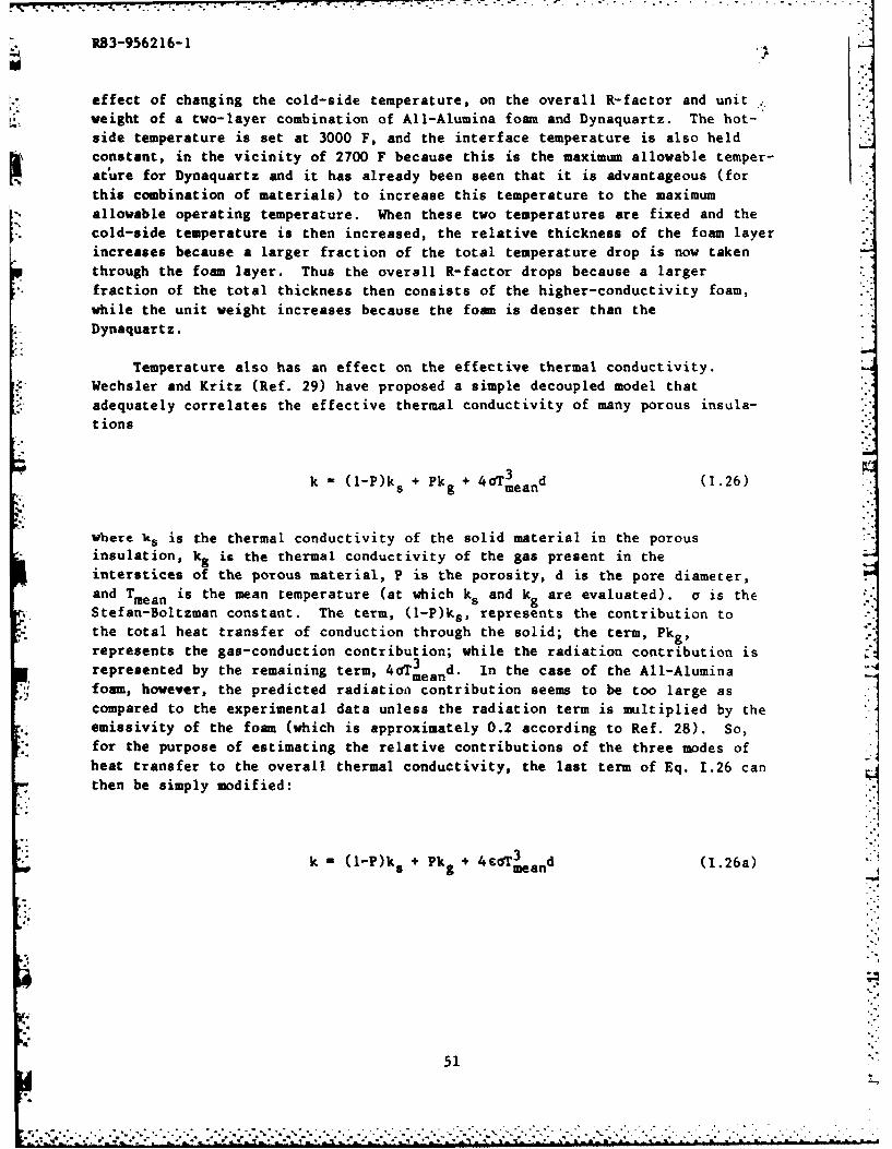
R83-956216-1
effect of changing the cold-side temperature, on the overall R-factor and unitweight of a two-layer combination of All-Alumina foam and Dynaquartz. The hot-side temperature is set at 3000 F, and the interface temperature is also heldconstant, in the vicinity of 2700 F because this is the maximum allowable temper-ature for Dynaquartz and it has already been seen that it is advantageous (forthis combination of materials) to increase this temperature to the maximumallowable operating temperature. When these two temperatures are fixed and the
* cold-side temperature is then increased, the relative thickness of the foam layerincreases because a larger fraction of the total temperature drop is now takenthrough the foam layer. Thus the overall R-factor drops because a largerfraction of the total thickness then consists of the higher-conductivity foam,while the unit weight increases because the foam is denser than the
Dynaquartz.
Temperature also has an effect on the effective thermal conductivity.Wechsler and Kritz (Ref. 29) have proposed a simple decoupled model that
adequately correlates the effective thermal conductivity of many porous insula-
tions
(l-P)ks + Pkg + 4oT3 d (1.26)
where ks is the thermal conductivity of the solid material in the porousinsulation, kg is the thermal conductivity of the gas present in theinterstices of the porous material, P is the porosity, d is the pore diameter,and Tmean is the mean temperature (at which ks and k are evaluated), a is theStefan-Boltzman constant. The term, (l-P)ks, represents the contribution tothe total heat transfer of conduction through the solid; the term, Pkg)represents the gas-conduction contribution; while the radiation contribution is
represented by the remaining term, 4 aTe and. In the case of the All-Alumina
foam, however, the predicted radiation contribution seems to be too large ascompared to the experimental data unless the radiation term is multiplied by the
emissivity of the foam (which is approximately 0.2 according to Ref. 28). So,for the purpose of estimating the relative contributions of the three modes ofheat transfer to the overall thermal conductivity, the last term of Eq. 1.26 can
then be simply modified:
k = (l-P)k s + Pk + 4dTmeand (I.26a)
51

R83-956216-1
Based on this modified formulation, Fig. 1.43 shows the relative contributionsof the heat transfer modes as a function of temperature, for an assumed porosityof 95 percent, an assumed pore diameter of 0.020 in., and an assumed emissivityof 0.2. Under these conditions at a mean temperature of 2900 F, the conductionthrough the solid ligaments carries approximately 56 percent of the heat, the
radiation contribution is approximately 27 percent of the total, while thecontribution from gas conduction is approximately 17 percent.
1.6.3 Preferred Retardation Configurations
Based on the preceding discussions, the preferred retardation configurations*.1
employing available materials can be identified. A two-layer configuration isthe simplest that can take hot-side temperatures of 3000 F and that also offers ahard and relatively smooth outer layer and a low-conductivity inner layer. Of
the available materials, All-Alumina foam is the preferred material for the outerlayer and Dynaquartz is the preferred material for the inner layer, because eachhas the lowest value of the insulation performance factor (pk) in its class.
If better mechanical properties are needed for the outer layer, then ceramiccomposites can offer more structure, but maximum operating temperatures of this
type of material are currently limited to only 1800 F. The overall combinationthat employs a ceramic composite as the outer layer will be significantly heavierthan one that uses a ceramic foam as the outer layer, unless the density ofceramic composites can be significantly reduced. Currently available compositematerials have a density of approximately 156 Ibm/ft3 , which is a factor ofapproximately ten higher than the density of All-Alumina foam, for example.
The inclusion of a third layer on the inside adds complexity to the overall
configuration. The main advantage of a third layer would be if the material hasa lower value of its insulation performance factor but is otherwise restricted in
its use to the colder side because of limitations in its maximum operatingtemperature. Because this additional layer would require its own attachmentgeometry, the third layer would appear to be worthwhile only if there were asignificant advantage in its insulation performance factor at the lowertemperatures over the material of the middle layer.
-5.4
.. o7
52
4...'.. ....... .......

R83-956216-1
REFERENCES
1. Giemza, C. J., W. B. Hunter et al.: Final Report on Structural Heat Shieldfor Reentry and Hypersonic Lift Vehicles - High Temperature Composite
Structure. Report No. ML-TDR-64-267, Part I, Vols. I and 2, 1965.
2. Scanlon, R. J.: U. S. Patent 3,802,145, assigned to Rohr Corporation,April 9, 1974.
3. Rolinski, E. J., et al.: Development of High-Temperature Insulation
Systems. AIAA Paper No. 66-43, 1966.
4. Kummer, D. L. and G. B. Bilow: Refractory Materials and Insulation. AIAAPaper No. 68-1128, 1968.
5. Chapman, A. J.: Evaluation of Reusable Surface Insulation for Space Shuttle
Over a Range of Heat-Transfer Rate and Surface Temperature. NASA TM X-2823,*' 1973.
6. Martynenko, V. V. et al.: Heat Insulation of High-Alumina Wool.Refractories, Vol. 19, No. 7-8 July-August 1979, p. 472-473.
7. Tobin, A., et al.: Development of a Closed Pore Insulation Material. NASAReport CR-2254, 1973.
8. Tobin, A. G.: U. S. Patent 4,016,229, assigned to Grumman Aerospace
Corporation, April 5, 1977.
9. Klett, R. D.: U. S. Patent 3,914,392, assigned to U. S. ERDA,October 21, 1975.
10. Ardary, Z. L., D. H. Sturgis, and C. D. Reynolds: U. S. Patent 3,793,204,
*i assigned to the U. S. AEC, February 19, 1974.
11. Deschamps, N. H. and G. L. Bernier: U. S. Patent 3,769,770, assigned to the
Sanders Nuclear Corp., November 6, 1973.
12. Asbury, J. J. and J. M. Googin: U. S. Patent 3,634,563, assigned to the
U. S. AEC, January 11, 1972.
53
*" R83-956216-1
REFERENCES (Cont'd)
13. Vogan, J. W. and J. L. Trumball: Metal-Ceramic Composite Materials. ReportNo. ML-TDR-64-83, 1964.
14. Allen, R. D. and W. M. Lysher: U. S. Patent 3,715,265, assigned toMcDonnell Douglas Corporation, February 6, 1973.
15. Nainiger, J. J.: Effect of Thermal Barrier Coatings on The Performance ofSteam- and Water-Cooled Gas Turbine-Stream Turbine Combined Cycle Systems.NASA Report TM-79057, 1968.
16. Shiembob, L. T.: Development of a Plasma Sprayed Ceramic Gas Path Seal forHigh Pressure Turbine Applications. NASA Report CR-135183, 1977.
17. Shiembob, L. T.: Development of a Plasma Sprayed Ceramic Gas Path Seal forHigh-Pressure Turbine Application. NASA Report CR-135387, 1978.
18. Shiembob, L. T.: Development of Improved High Pressure Turbine Outer GasPath Seal Components. NASA Report CR-1519801, 1980. W
19. Pechman, A. and R. M. Beasley: U. S. Patent 3,955,034, assigned to NASA,May 4, 1976.
20. Hurwicz, H. and R. Mascola: Thermal Protection Systems - ApplicationResearch of Materials Properties and Structural Concepts. Report No. ML-TDR-64-82, 1965.
21. Weinberg, E. K.: U. S. Patent 3,725,282, April 3, 1973.
22. Strauss, E. L.: Structural and Heat Transfer Characteristics of Resin-Impregnated Porous Ceramics. American Ceramic Scoeity Bulletin, Vol. 42,1963, pp. 444-447.
23. Maloof, S.: Tungsten-Base Composites. Astronautics, Vol. 6, No. 4, April,1961, p. 36.
24. Clavson, J. F.: Thermal Correlation of Heat Protection System. ReportAFDL-TR-65-167, 1965.
25. Rathjen, K. A.: CAVE: A Computer Code for Two-Dimensional TransientHeating Analysis of Conceptual Thermal Protection Systems for HypersonicVehicles. NASA Contractor Report 2897, 1977.
54
[,,- ,, ~~~~~~~~~~~~~~~~~~.-.. .. ...... ......... •.-.- . ... ; ,.. .. • .. . - .. '.,", ,_-'. •. . . ..

R83-956216-1
REFERENCES (Cont'd)
26. Garcia, F., and W. T. Fowler: Thermal Protection Optimization for the Space
Shuttle, AIAA Paper No. 72-977, 1972.
27. Robinson, C. A.: Laser Technology Demonstration Proposed. Aviation Week
and Space Technology, February 16, 1981, pp. 16-19.
28. Wechsler, A. R. and P. E. Glaser: Investigation of the Thermal Properties
of High-Temperature Insulation Materials. Technical Documentary Report No.ASD-TDR-63-574, 1963.
29. Wechsler, A. R. and M. A. Kritz: Investigation and Development of High
Temperature Insulation Systems. Technical Report AFML-TR-138, 1965.
30. Strauss, R. L.: Evaluation of Low Cost/High Temperature Insulation. NASA
CR-134902, 1975.
31. Brennan, J. J. and K. M. P. wo: Silicon Carbide Fibre Reinforced Glass-
Ceramic Matrix Composites Exhibiting High Strength and Toughness. J.
4 IMaterials Science, Vol. 17, 1982, p. 2371.
32. Prevo, K. M. and J. J. Brenn~an: J. Materials Science, Vol. 15, 1980, p.
463.
33. Prewo, K. M. and J. J. Brennan: J. Materials Science, Vol. 17, 1982, p.
1201.
34. Ready, J. F.: Laser Applications in Metal Working. Society of
Manufacturing Engineers Paper No. MRR75-06, 1975.
35. Schriempf, J. T.: Response of Materials to Laser Radiation: A Short
Course. Naval Research Laboratory Report 7728, 1974.
36. Lundell, J. H. and R. R. Dickey: Response of Heat-Shield Materials toIntense Laser Radiation. In "Outer Planet Entry Heating and ThermalProtection", R. Viskanka, ed. Vol. 64 in "Progress in Astronautics and
Aeronautics", 1979.
55 -
R83-956216-1.17
REFERENCES (Cont'd)
37. Crane, K. C. A. and J. R. Brown: Laser-Induced Ablation of Fibre/epoxyComposites,. J. Phys. D: Appl. Phys., Vol. 14, 1981, p. 2341-9.
38. Crane, K. C. A., R. K. Garnsworthy, and L. E. S. Hathias: Ablation ofMaterials Subjected to Laser Radiation and High-Speed Gas Flows. J. Appl.Phys., Vol. 51, No. 11, November, 1980, pp. 5954-61.
39. Cerablanket Aerospace Insulation Product Brochure. Manville Corporation, -1980.
40. Min-k Thermal Insulation Product Brochure. Manville Corporation, 1982.
41. All-Alumina Refractory Fiber Insulation Product Brochure. RIM Products
Corporation.
42. Rohsenow, W. M. and J. P. Hartnett, eds.: Handbook of Heat Transfer.
McGraw-Hill, 1973.
43. Giedt, W. H.: Principles of Engineering Heat Transfer. Van Nostrand,
1957.
5.6
56
r.:
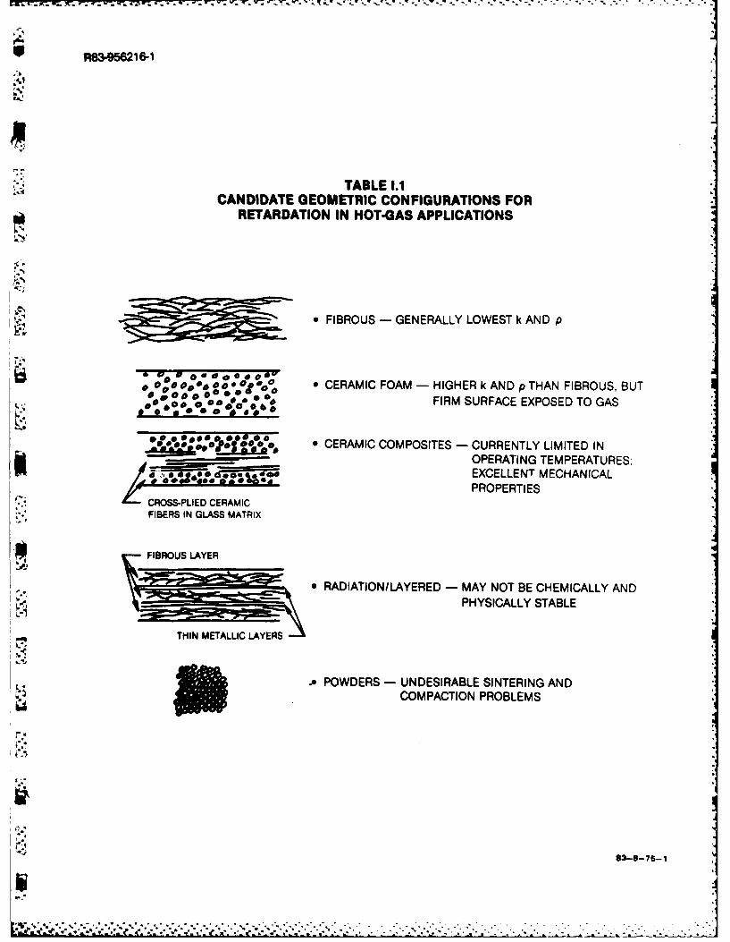
"" R83-956216-1
.4
TABLE 1.1CANDIDATE GEOMETRIC CONFIGURATIONS FOR
RETARDATION IN HOT-GAS APPLICATIONS
* FIBROUS - GENERALLY LOWEST k AND p
o 0 .O0 o , a,Oooop o * CERAMIC FOAM - HIGHER k AND p THAN FIBROUS, BUTDo 00a00 oa 0 0 % FIRM SURFACE EXPOSED TO GAS
, CERAMIC COMPOSITES - CURRENTLY LIMITED IN______ " 'OPERATING TEMPERATURES;
o *EXCELLENT MECHANICALo - . 0 0 6 e % o , rP R O P E R T I E S
CROSS-PLIED CERAMICFIBERS IN GLASS MATRIX
FIBROUS LAYER
* RADIATION/LAYERED - MAY NOT BE CHEMICALLY AND
-Ci
PHYSICALLY STABLE
THIN METALLIC LAYERS
0 POWDERS - UNDESIRABLE SINTERING ANDCOMPACTION PROBLEMS
I-,
83.875-

R83-956216-1
.. o
TABLE 1.2CANDIDATE MATERIALS VS CANDIDATE CONFIGURATIONS
FIBROUS
DYNAQUARTZ (SILICA) - MOST EFFECTIVE INSULATION UP TO 2700 F
ALUMINA - STABLE UP TO 3200 F, BUT HIGH COST
ZIRCONIA - UNDESIRABLE SHRINKAGE AND REACTION ATTEMPERATURES OVER 2500 F
GRAPHITE - LIMITED TO VACUUM APPLICATIONS; HIGH k
MIN-K - LIMITED TO 1800 F
FOAM
ALUMINA - REASONABLY LOW k
ZIRCONIA - SHRINKAGE AND REACTION PROBLEMS
SILICON CARBIDE - HIGH k
CERAMIC COMPOSITES
COMPGLASTM - SiC-FIBER REINFORCED GLASS CERAMIC"CURRENTLY LIMITED TO 1800 F BECAUSE OFOXIDATION PROBLEMS
RADIATION/LAYERED
DYNAQUARTZ WITHTANTALUM RADIATIONSHIELDS - DIFFICULT TO APPLY IN REAL SYSTEMS WITH
CURVED SURFACES OR SMALL DIMENSIONS
83-8-75-2

R83-G56216-1 FIG. 1.1
TYPICAL EXAMPLE OF HEAT TRANSFER RETARDATION DEVICE
HEAT LOAD X THIN CERAMIC COATING
I Illl~l~l~ll FOAMED CERAM IC IN-, METAL HONEYCOMB CORE
FIBROUSINSULATIANjWW
METAL FACE SHEET
82-5-2-5

I., 4562i 6-1
polWEf LVE FOR PASSIVE LASER CoU4TERMEASU
I.-
10
-
U.
0
01
0 ~ ~~LASER POWEWcm
93-8754

R83-9521 61 FIG. 1.3
ELAPSED TIME FOR SURFACE MELTING
7
6
x 5
w ATJ GRAPHITEcc
c-
.00
ILL3,, T M 4 00 0OK
5 I 3500 K
2
0 j 1.4 HEAT FLUX, kW/cm2 1
83-8-75-5
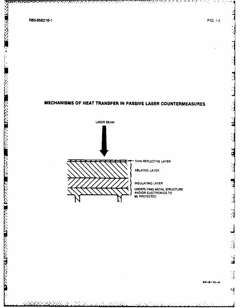
R83-956216-1 FIG. IA4
MECHANISMS OF HEAT TRANSFER IN PASSIVE LASER COUNTERMEASURES
LASER BEAM
- - -- - THIN REFLECTIVE LAYER
ABLATIVE LAYER
xzzz ZzzzINSULATING LAYER}UNDERLYING METAL STRUCTUREN. AND/OR ELECTRONICS TO
BE PROTECTED
L4

R83-95621 6-1 FIG. 1.5
EFFECTIVE THERMAL CONDUCTIVITY OF SELECTED MATERIALS
2.0
1.0
COMPGLASTMl
DYNAOUARTZALUMINA FOAM (VAC) (4.5 Ibm/ft3)
u- 0.50.4 (3RbmNEt3 RIM ALL-ALUMiNA
(3 Ib/It 3 )FOAM
>. 0.3 SIC FOAM (VAC)
o 0.2z8
DYNAOUARTZ (VAC)cc' (6.2 Ibm/ft3)
S 0.1
S0.08- DYNAOUARTZ WITH 2 TANTALUM0 RADIATION SHIELDS (VAC)
LL 0.06 (. blt
N-AIR* 0.04
VALUES IN AIRUNLESS OTHERWISE STATED)
DYNAOUARTZ (VAC)(6.7 Ibm/?l)
0.01 III1000 1500 2000 2500 3000 3500-
MEAN TEMPERATURE OF MATERIAL, F
83-8-75-7

R839521-1INSULATION PERFORMANCE FACTOR FOR SELECTED MATERIALS FG .
40.0
'-p"
SiC FOAM (VAC)10.0- ALUMINA FOAM (VAC)
E.0
0 CERACHROME
* g. REFRACTING FELT
IL. THERMOFLEX I1-FIBROUS 1 ORNC
W CERAMIC BLANKET
Z RIM ALL-ALUMINA
0U-
0 DYNAOUARTZ
(6.2 Ibmlft3) - VAC
MI* CERABLANKETz
DYNAOUARTZ (6.2 Ibmlft3)
.4 DYNAOUARTZ (4.5 Ibm/fl 3)
DYNAOUARTZ (6.7 Ibmtfl 3 ) - VAC
VALUES IN AIR UNLESSZIRCONIA FIBERS OHRIESAE
N REPRESENTS MAXIMUM0-FIBER FELT OPERATING TEMPERATURE
1000 1500 2000 2500 3000 3500
MEAN TEMPERATURE OF MATERIAL, F

F183-956216-1 FIG. 1.7
5* 1.0
0.8
c-
0.6
-J - POLISHED SILVER
W 0.4 D-NCE
.2
0.2O LASER AT 10.6As
0.2 0.4 0.6 1.0 2.0 4.0 6.0 10.0 20.0
LASER WAVELENGTH (MICRONS)
i-4
83-8-75-9

-- ,
R83-956216-1 FIG. 1.8
TEMPERATURE DEPENDENCE OF THE REFLECTIVITY OF ALUMINUM
1.0
0.909-ALUMINUM (HIGH-PURITY FILMS)
cc 0.8
E00 o.7 .
0 6 POLISHED ALUMINUM
IJ.
< 0.6
S0.5-i,UA
cc 0.4
0.3-
0.2 I I I I I I I I I0 100 200 300 400 500 600 700 800 900 1000
TEMPERATURE, K
Ja3-s-7s-1O
........!!o. -

R83-M5216-1 FIG.I.9
LASER PENETRATION RATES
44
CARBON PHENOLIC
3 CARBITEX 100
E
Q GLASS/EPOXYw /
/ ATJ GRAPHITE
zo 2 SS5304
wu KEVLAR/EPOXYz
TITANIUM ALLOY 6A1-4V
/SS 3102
CARBON STEEL 1020
1 CARBON/EPOXYj
0 L0 25 50 75
NOMI NAL AVERAGE BEAM INTENSITY,kW/cm2
83-8-75-11

j R83-956216-1 FIG. 1.10
F'
LASER RETARDATION DEVICE USING GAS CAPSULES
I I--I DIAMETER OF
LASER BEAM
I II I
* 4I I
I I
00000 0 0.00 0 0 b0 0o.0 *. . 0 a @0v v0 0 **au0 9 OVI
0 0 00 0 0 0 000v 000..0 0 o 0 " o 00
giC @o*~~ .:o:0 0 0 :0LCPSULES CONTAIN GAS ANDARE EMBEDDED IN ABLATIVEMATRIX
83-8-76-12
,g .4
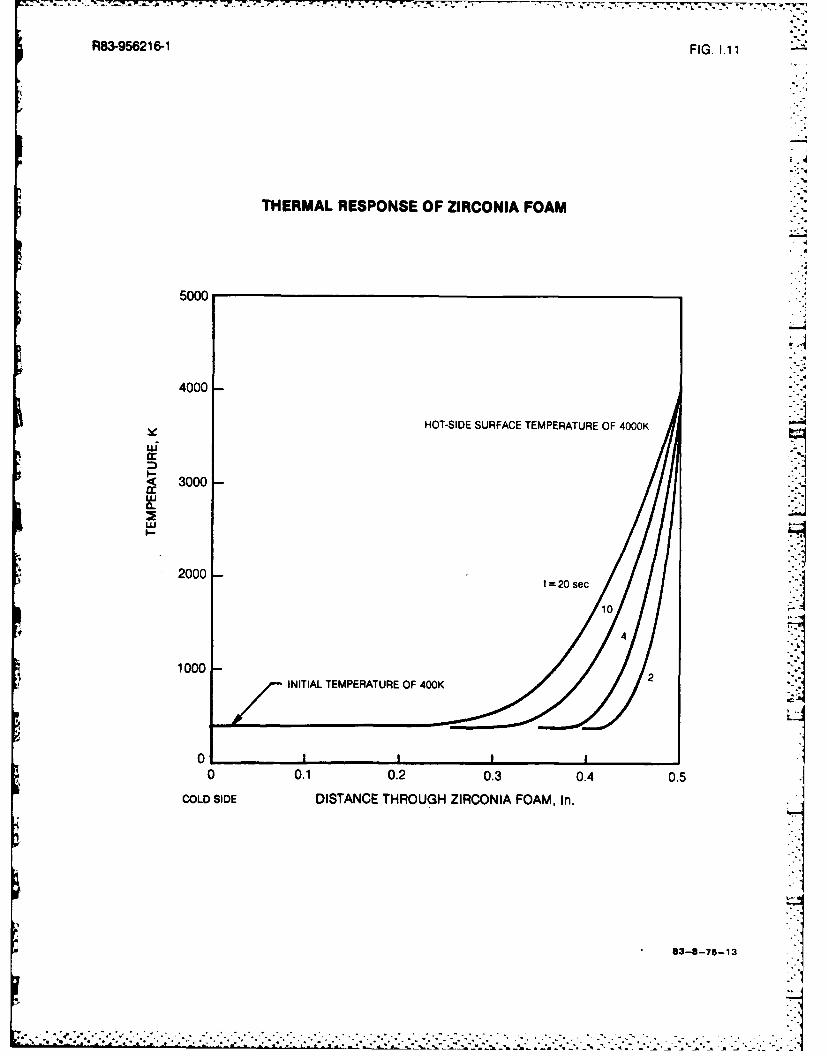
'4 4
R83-956216-1 FIG. 1. 1
THERMAL RESPONSE OF ZIRCONIA FOAM
5000
4000
HI
Ld
I-1
3000
2000 -'
2000 t20 sec
10
4
1000 _ _ _ _ _ _ _ _ _ _ _ _ _ iINITIAL TEMPERATURE OF 400K
0 0.1 0.2 0.3 0.4 0.5
COLD SIDE DISTANCE THROUGH ZIRCONIA FOAM, In.
83-8-75-13 1
**-* : - ooo -.*.i- . I

R83-95621 6-1 FIG. 1.12
SPACE-AVERAGE TEMPERTURE OF ZIRCONIA FOAM
5000
* 4000M- HOT-SIDE AT 4000 K0.5 in. THICK SLAB
0
~300N
4.-. U.0
2000
0
10 1000 45
ELAPSED TIME, sec
4' 83-8-75-14
.iz

R83-956216-1 FIG. 1.13
RATIONALE FOR MULTI.LAYER RETARDATION DEVICE
OUTER LAYER: CERAMIC FOAM OR CERAMIC COMPOSITE, SO THATLOOSE FIBERS WILL NOT BE EXPOSED TO AND TORNOFF BY HIGH-VELOCITY GAS
INNER LAYER(S): FIBROUS, BECAUSE LOWER k ANDp THAN CERAMICFOAM OR CERAMIC COMPOSITE
THOT UNDERLYING METALSTRUCTURE
HEAT FLUX
q/A
TCOLD
HOT GASFLOWF4INNER LAYER
OUTER LAYER
83-8-75-15
II

* -*-' . r,. -'W .
R83456216-1 FIG. 1.14
APPROACHES TO REDUCE DENSITY OF CERAMIC FOAM
STACK OF GROOVED LAYERS AXIAL HOLES CAST INTO FOAM
i" q
I -i r k r- r- - i r 9 ri i-i r9 I
a l l a-I l r--l a-Il r ' a l al r'i
CZ.- a) RECTANGULAR GROOVES
b) TRIANGULAR GROOVES
8 8 5
J83- 8- 75-16 "
€,,.; . . .. .
-', -"-' ".;". "- -_ " ,-,' ... .. ." .-.'-"--"--,"--"-.----"-"----',-----.------"----".-----,-"--",-"'"."--"--"--"'

R83-956216-1FI.15
CANDIDATE MATERIALSICON FIG URATIONS COMBINATIONS FOR ANALYSISRETARDATION FOR HOT GAS APPLICATIONS
OUTER LAYER
HIGH TEMPERATURE CAPABILITYRELATIVELY SMOOTH SURFACE
INNER LAYER(S) - LOW K
Aq
q q q
wlALUMINA FOAM ALUMINA FOAM AUIAFA
DYNAOUARTZ
DYNAOUARTZ (FIBROUS) CERABLANKET (FIBROUS) MIN-K (FIBROUS)
COMPGLASTM COMPGLASTM COMPGLASTM
DYNAOUARTZ
DYNAOUARTZ CERABLAN KETL __ ____ ___ ___ ____ ___MI N-K
83-8-75-17

R83-95621 6-1 FIG. 1.16
U))
w L
wwAcc
xw -J
U)l
W 9)
02 0>co >WUjLL az U) w
<A.
z L)
00z
00 0 - 0
n 0 < 0 < 0
w LU ED U>- z
0 < 0 CO <
(0 -l>u
-' <8 0!R z
0 ~ ___ >- 6JDU >
cc.- - - CCLLc

R83-956216-1 FIG. 1.17
HEAT TRANSFER MODEL OF THREE-LAYER RETARDATION DEVICE
T c AT THRU LAYER 1
TMID AT THRU CONTACT RESISTANCE 12
AT THRU LAYER 2
GAS IAT THRU CONTACT RESISTANCE 23
FLO W TMIN-KAT THRU LAYER 3
TCOL
T
LAYER 3 LAYER 2 LYER1
63
x
83-8-75- 19

R83-956216-1 FIG. 1.18
THERMAL CONTACT CONDUCTANCE
50=
- 2000-
uj 1000
I- 500-
0
820
8 - 0
2 5 10 20 50 00 00 500 1000
CONTACT PRESSURE, psi
Cure MteralRMS surface GaMatral ean contact
ct Maeilpair finish (IL in.) Ga aeil temp. (*Fg
I aluminum (2024413) 48-65 vacuum (10-4 mm Hg) 1102 alumninumn (2024-T3) 6-18 vacuum (10- 4 MM Hg) 1103 aluminum (2024413) 6-8 (not flat) vacuum (10 -4 mm Hg) 1104 aluminum (75S.T6) 120 air 2005 aluminum (7S.T6) 65 air 2006 aluminum (7SS-T6) 10 air 2007 aluminum (20244T3) 6-8 (not flat) lead foil (0.008 in.) 110B aluminum (75S.T6) 120 bra foil (0.00 1 in.) 2009 stainless (304) 42-60 vacuum (10- mm Hg) 65
10 stainless (304) 10-15 vacuum (10-: mmHg) 85I I tainiessa(416) 300 air 20012 stainles(416) 100 brass foil (0.001 in.) 20013 nugnesium (AZ-31 B) 50-60 (oxidized) vacuum (10 6 mm Hg) 6514 nupiesium (AZ-3 15) 9-36 (oxidized) vacuum (10-4 mm Hg) 85IS copper (OFHC) 7-9 vacuum (104 mm Hg) 11516 sta~nles/aluminum 30/65 air 20017 Iron/aluminum -air s0I8 ttanptqoU/papwite -air 270
83-8-75-45
. 2.
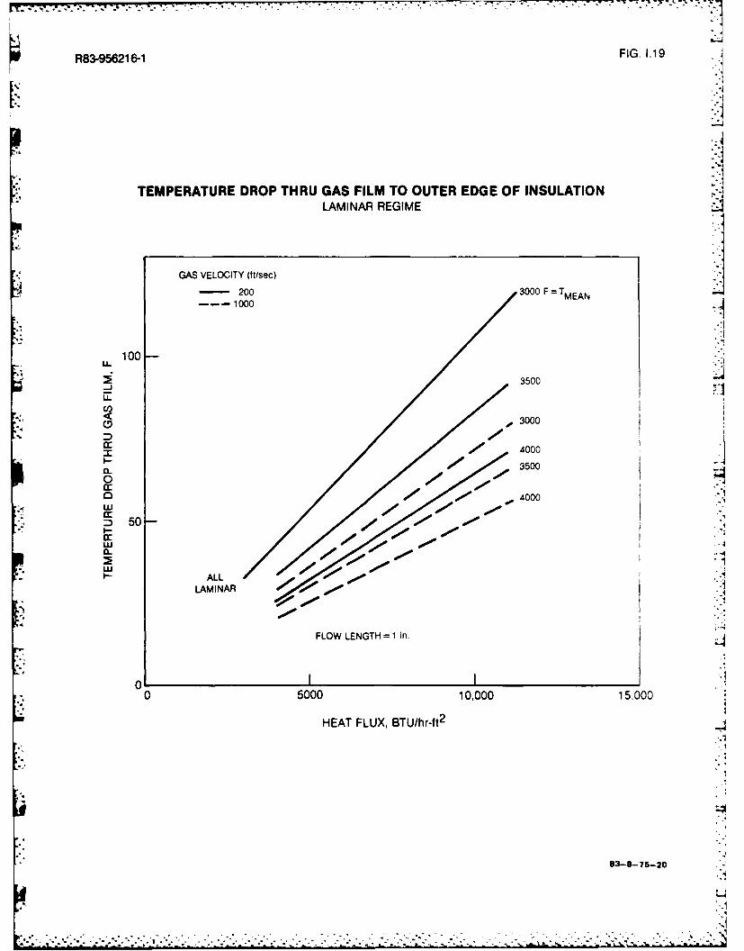
R83-95621 6-1 FIG. 1.19
TEMPERATURE DROP THRU GAS FILM TO OUTER EDGE OF INSULATIONLAMINAR REGIME
GAS VELOCITY (ftisec)- 200 3000 F T TMEANj
100-
-J 3500
D Id
m 00 3 000
* 35002
0
~50-
CAL ALLLAM1NAR
L .1
0 5000 10,000 15,000
HEAT FLUX, BTU/hr-ft 2
L4
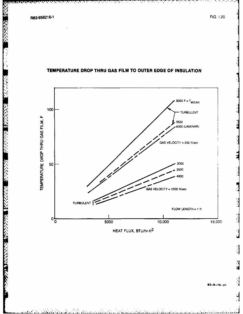
ax .. -..
R83-9562 16-1 FIG. 1.20
TEMPERATURE DROP THRU GAS FILM TO OUTER EDGE OF INSULATION
3000 F T MEAN
4, 100 -TURBULENT
3500
LL. 4 4000 (LAMINAR)
cr GAS VELOCITY =200 f t/sec
005000 0 30
a: 4 1 .00 3000
I-CL Z-OO4000
GSVELOCITY = 1000 itisec
TURBULENT
FLOW LENGTH =1 ft
00 5000 10,000 15.000
HEAT FLUX, BTU/hr-ft 2
a. 83-8-75-21 d

R8-561- FIG. 1.21
HEAT TRANSFER MODEL OF TWO-LAYER RETARDATION DEVICE
AT THRU LAYER 1
AT THRU CONTACT RESISTANCE
1FLOW AT TI-RU LAYER 2
TT
METALSTRUCTURE
83-8-75-22

RB3-96216-1 FIG. 1.22
THERMAL PERFORMANCE OF TWO-LAYER RETARDATION DEVICE* THO 3000 F
* RETARDATION GEOMETRY
3000 F TMID DYNAOLJARTZ FIBERS
P2 =6.2 Ibmft 3
ALL-ALUMI1NA FOAMP, 14 Ibmlft 3
1200 F
61 62
10,000THICKNESS OF INNER LAYER, i
co~
2:0
0.375
- 5000-0.50
cc
z 1.0
ti LINES OF EQUAL
CI "Wft Ifftt ftf WEGT I b
0 2200 2400 2600 2800 3000 3200
INTERFACE TEMPERATURE, F
83-6-75-23

R83-956216-1 FIG 1.23
THICKNESS OF TWO-LAYER RETARDATION DEVICE3THOT = 3000 F
RETARDATION GEOMETRY
3000 F TMID DVNAOUARTZ FIBERS
P2 =6.2 Ibmift3
ALL-ALUMINA FOAM
Pl 14-Ibm/3
1200 F* .-
61 62
3
L+
20
'4.. 0
z 1.0
0.75-j
0.625
o 0.50
0.375
62 =0.25 in.
I I I2200 2400 2600 2800 3000 ,0INTERFACE TEMPERATURE, TMID, F
83-8-75-24

R83-956216-1 FIG. 1.24
R-FACTOR OF TWO-LAYER RETARDATION DEVICE
RETARDATION GEOMETRY4
300 FfMI DYNAOUARTZ FIBERS
P2 =6.2 Ibm/ft 3
ALL-ALUMINA FOAMAP1 =14 Ibm/ft3
_ j-
1200 F
61 6 o
2
UL
d 0%
0
d: 1.0
0.75
U' 0.625
0.500.375
62=0.25 inl.
00 2200 2400 2600 2800 3000
INTERFACE TEMPERATURE, TMID, F
83-8-75-25
tj

P83-96216-
FIG. 1.25
WEIGHT OF TWO-LAYER RETARDATION DEVICEITHOT = 3000 F
RETARDATION GEOMETRY
3000 F TMID DYNAOUARTZ FIBERS
P2 6.2 Ibmr/ft3
ALL-ALUMINA FOAMp, 14 Ibm/fl 3 _,,
1200 F
61 62
3621.0 in.
'4b2
0.75
E20.625
9 1500~~
I.-.,0.50z LINES OF EQUAL20-
- HEAT TRANSFER 2O-.LL 2
0 (BTU/hr-ff
0.2
4000
0 2200 2400 2600 2800 3000
INTERFACE TEMPERATURE, TMD, F
83-8-75-26

R83-956216-1 FIG. 1.26
WEIGHT AND OVERALL R-FACTOR OF TWO-LAYER RETARDATION DEVICE
I THO =3000 TMIDDYNAOUARTZ (6.2 Ibm/ft3 )
ALL-ALUMINA -FOAM(14 Ibm/ft
3)
TCOLD= 1200 F .
0.75
'-4
0.50 TMID =280 0 F
0 0
c 0.25
0 0
1.0
C/)
4xz
.0.75-
z0
V...
4 00.25-O
0 j'
-~-rw
4; 00 0.25 0.50 0.75 1.0
TOTAL THICKNESS OF INSULATION, 61 +62, in.
83-6-75-27
...

U-S 7
R83-956216-1 FIG. 1.27
RELATIVE LAYER THICKNESS FOR TWO-LAYER RETARDATION DEVICE
THOT =3000F T MIDDYNAOUARTZ (6.2 Ibm/It 3)
ALL-ALUMINA--..FOAM114 Ibmn/tl 3)
TCOLD 1200 F
5
* ' 4
cj
zy 3
2-
52
0 ~'2200 2400 2600 2800 3000
INTERFACE TEMPERATURE, TMID F
83-8--75-28

R83-6261 FIG. 1.28
WEIGHT AND OVERALL R-FACTOR OF TWO-LAYER RETARDATION DEVICE7
THOT 3000 F TMIDDYNAOUARTZ (4.5 b/t
ALL-ALUMINAFOAM(14 Ibm/1t
3~
TCOLD 120 0 F
0.75
0. 50- MID~ 280
0 20
;4a:0.25
_j
0 0
0.75
£0.500 20
z 0.25U-0
00 0.25 0.50 0.75 1.00
TOTAL THICKNESS OF INSULATION, 61 + 62 n.r
83-8-75-29
711

R83-95621 6-1FI.12
RELATIVE LAYER THICKNESS FOR TWO-LAYER RETARDATION DEVICEALL-ALUMINA FOAM/DYNAQUARTZ
!pTHO 3000 F TMI
DYNAOUARTZ (4.5 Ibmlft)
ALL-ALUMINAFOAM(14 Ibm/ft 3~
T COLE) 120 0 F
5
4
Z 3-
C-,ui
00 2400 2600 2800
INTERFACE TEMPERATURE, TMID, F
t.. 83-8-75-30

R83-956216-1 FIG. 1.30
OVERALL R-FACTOR AND UNIT WEIGHT OF TWO-LAYER RETARDATION DEVICE
THOT =3 00 0 F TMID
CERABLANKET (3 tbmfft3)AL.L-ALUMINAFOAM(14 Ibm/It3)
TCOLD= 1200 F
0.75
- C0.50 20
001.0
CL
S0.25
0
0
1.00
* 0
0 0.50.5 .7 10
IInTOTA THCNS0FISUAIN1+2
83-875-5

R83-956216-1 FIG. 1.31
RELATIVE LAYER THICKNESS OF TWO-LAYER RETARDATION DEVICEALL-ALUMINA FOAM/CERABLANKET
THOT = 3000 F TMID CERABLANKET (3 IbM/ft 3
ALL-ALUMINA-,,FOAM(14 IbC Alt(33)
TCOLD= 1200 F
61 -. I 2-43
C-)
I£ -
uj
w
0 0 1600 2000 2400
INTERFACE TEMPERTURE, TMID, F
83-8-75-32

R83-956216-1 FIG. 1.32
OVERALL R-FACTOR AND UNIT WEIGHT OF THREE-LAYER RETARDATION DEVICEALL-ALUMINA FOAM/DYNAOUARTZ/MIN-K
THOT =3000 F TMID DYNAOUARTZ (P2 = 4.5 IbmlItI
MIN-K (P3 = 20 Ibmfll3 )
ALL-ALUMINA TMINKFOAM
(14 Ib /-t3) TCOLD= 1200 F
6,.-t I.--62-.m. k--.30.8
TMINK (F)
1800TMID = 290 0
1600
m 0.6-
C'.j 2800
o 0.4-," I-
c< 0.2--'0
-' 0
0.6TMINK (F)
.- 1800
E 1600m 0.61 TMID= 2 800 F 1800Z, 16000
Z 0.4- 2900
U.o0
I-I
,%bU' 0.2-C,,• -
z
.4 00 0.25 0.50 0.75 1.00
TOTAL THICKNESS OF INSULATION, 61 + 62 + 63, in. 3--9-33

U R83-956216-1 FIG. 133
RELATIVE LAYER THICKNESS FOR THREE-LAYER RETARDATION DEVICEALL-ALUMINA FOAM/DYNAOUARTZ/MIN-K
THOT 3000 F TMID DYNAOUARTZ (P2 = 4.5 Ibm/f13 )
T M0MIN-K (p3 20 Ibm/f 3 )
ALL-ALUMi:A TMINKFOAM(14 Ibm/ 3) TCOLD= 1200 F
Vo1-- -04-. F 63
10
c1 MIN-K (F)= 1600
uii
" 1800
2""
c 6
z
I- 62/611
u 4
Lu
UJI 2
- 63161 1800
"3 1600
0 2400 2600 2800 3000
TEMPERATURE, TMID, FI8 7
83-8-75-3d
d
*. . .. .. . . . . .. _

jD-R133 589 HEAT TRANSFER RETARDATION AT ELEVATED TEMPERATURES 212PHASE I ANALYSrS OF HE.. (U) UNITED TECHNOLOGIESRESEARCH CENTER EAST HARTFORD CT C Wd DEANE SEP 83
UNCLASSIFIED UTRC/R83-956216--i N0e014-82-C-0671 F/Il 20/0 3
EEm

Lu
III'
*I125 11.
MICROCOPY RESOLUTION TEST CHARTNATIONAL BUREAU OF STANDARDS-1963-A

.2. .S . & .. .. :-w I~ 'v -T P S S- *~- . -
RS3-156216-1 FIG. 1.34
OVERALL R-FACTOR AND UNIT WEIGHT OF TWO.LAYER RETARDATION DEVICECERAMIC COMPOSITE/DYNAOUARTZ
THOT = 3000 F TMID
HYPOTHETICAL CERAMIC DYNAOUARTZ (4.5 Ibmt
3
COMPOSITE(p1 156 Ibm/ft
3 )
TCOLD = 1200 F
0.5 TMID (F) 2950
0.4 2900
N 0.3 2800
000
4 0.2S/00
-j_j
'=" 0.1
10
ci
2 TMID (F) 28000
U)
0I ~~29
U.
22
S2 .00z
0 0.25 0.50 0.75 1.0
TOTAL THICKNESS OF INSULATION, 61 + 62 , in.s5.-4-7-as
41' -

RBSI-5M 16-I1 FIG. 1.35
RELATIVE LAYER THICKNESS FOR TWO-LAYER RETARDATION DEVICECERAMIC COMPOSITEIDYNAOUARTZ
THOT =3000 F T MID
DYNAQUARTZ (4.5 Ibmlf1%3
HYPOTHETICAL CERAMIC
COMPOSITE (p1 - 156 tbm/113 I -
TCOLD= 12D0 F
3~] ~
44
* - -
*0260 80 30
INERAC 3EPRTRE MD
Z,
838753

RSS%9M81 6-1 FIG. 1.36
OVERALL R-FACTOR AND UNIT WEIGHT OF TWO-LAYER RETARDATION DEVICECERAMIC COMPOSITEICERABLANKET
THoT =30 0 0 I T MIDCERABLANKET (3 ibm/U3
HYPOTHETICAL CERAMICCOMPOSITE (p1 - 156 Ibm/ft3 a
TCOLD =1200 F
0.20
0.15
0 I-0.10-
< :
m0.050j
0-y12
a- 240
LL.0
I. 4 -
~ 0 0.25 0.50 0.75 1.01
TOTAL THICKNESS OF INSULATION, 6 1 +% 62,in
83-8-75-37
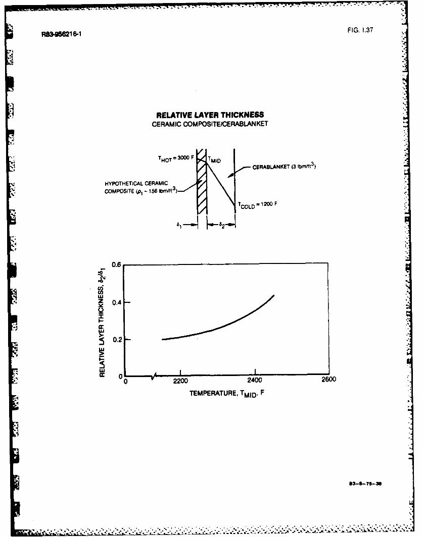
R83-956216-1 FIG. 1.37
RELATIVE LAYER THICKNESSCERAMIC COMPOSITEICERABLANKET
THOT =M3 0 0 0 F ID,, CERABLANKET (3 Ibm/ft3 )
HYPOTHETICAL CERAMIC
COMPOSITE (p1 - 156 Ibmftl3)
TCOLD= 1200 F
4..t"2
0.6
Z 0.4
0.2-01
02200 2400 2600.
TEMPERATURE, TMIo . F :
I%p --p 13.8-?15-30w
• ... ..."....,.".,. --..",".;."- - .--'.;.":'::.....'',,'", .." ".'"'' '" :"50.2 .,.,. . ... .... . . ...":'." "? ':;:,: ' ,_":

R83-56216-1 FIG. 1.38
OVERALL R-FACTOR AND UNIT WEIGHT OF THREE-LAYER RETARDATION DEVICE
THOT - 30 0 0 F TMID DYNAOUARTZ (k = 4.5 Ibm/ft3
)o IF
,MIN-K % = 20 Ibm/ft 3)
HYPOTHETICAL TMIN"ICERAMIC COMPOSITE.,156 Ibmtrt3 ° '2 ' F
0.5 TMIN-K
D 0.4 1600
i 0. 1800
0 0.
,. TMD=TMIN. K$#60
28000.2
-J
0.1
* 010 IN
TMNN
1800
.6- 1- / 800
TMI 280Iz 10
0
0 0.25 0.50 0.75 1.0
TOTAL THICKNESS OF INSULATION, 6i +62 +63, in.
13-1-75-39

7_ -: .. . . . . . . . . .
ft83-956216-1 FIG. 1.39
N RELATIVE LAYER THICKNESS FOR THREE-LAYER RETARDATION DEVICE
1.6THT F TMDDYNAOUARTZ 02 4 5 IbM/ft 3)
1.4 MIN-K (3=20 Ibm/f13)
HYPOTHETICAL TI.CERAMIC COMPOStITE
(p- 156 Ibm/ t3) TCOLD = 1200 F
1.2 I
cw,
1.0 -,coz
o0.8-
w 0.6 /
4'. 0.4 -
TMIN-K0.2 TMNK()6/11800
160 woO 1600
080
0 2400 2600 2800 3000* TEMPERATURE, TM ID, F
83-8-7s-4o

R83-956216-1 FIG. 1.40
EFFECT OF INNER MATERIAL ON OVERALL Rt-FACTOR AND UNIT WEIGHT
THOT = 300 0 F TMImm 13000F DYNAOUARTZ (2
ALL-ALUMINA FOAMPi= 14 IN)Mt 3
TCLD =1200 F
0.75
DYNAOUARTZ LAYER.c0.50-
0262Imf= .5-mf
02
TMID 280 0 F
4 0
cy 0.75
2 DYNAQUARTZ LAYER~0.50-
zL
22
0 0.25 0.50 0.75 1.0
TOTAL THICKNESS OF INSULATION, 61~ +62, in.

R83-56216-1 FIG. 1.41
EFFECT OF OUTER-LAYER MATERIAL ON OVERALL R-FACTOR AND UNIT WEIGHT
THOT = 3000 F TMIDDYNAOUARTZ (4.5 IIbmVtt 3)
OUTER LAYER
Y TCOLD= 1200 F
0.8
4 0.6-
OUTER LAYER
.- ' ALL-ALUMINIA FOAM
S02.OHYPOTHETCAL
I 0 CERAMIC COMPOSITETMI D =2800 F
10
c'J
OUTER LAYER /6-/
D/IL
0 4f HYPOTHETICAL
/ CERAMC COMPOSITE
2 // ALL-ALUMINA FOAM
0 0.25 0.50 0.75 1.0TOTAL THICKNESS OF INSULATION, 61 +62, i2.
83-4-75-42
Um al

R83-95621 6-1 FIG. 1.42
EFFECT OF TEMPERATURE ON RETARDATION AND WEIGHT CHARACTERISTICS
THO= 3 0 F TM,HOT MIDDYNAOUARTZ (4.5 Ibmltft3)
ALL-ALUMNAFOAM(14 bmflt)
T$ COLD
0.75
0.50- -0
0
C 0.25
00
0 0.75'TOLD 280 80
.0
00
~ 0 0.25 0.50 0.75 1.00 1.25
TOTAL THICKNESS OF INSULATION, 61 + 62, inl.
33-8-75-43

- , ,L.. ,, . . .. . . ' ,
- . . .. . .. .'-.' ,1
R83-956216-1 FIG. 1.43
I RELATIVE CONTRIBUTIONS OF HEAT TRANSFER MODES
0.8
0.7 SOLID CONDUCTION
0.6z0
" 0.5
v 0
, 0.4ALL-ALUMINA FOAM
0 0.4
i, ..
c 0.3 -
k' ' MADAN EPRAlTUR,
I'
0.2
GAS CONDUCTION Q01ASQTOT
0.1
0-0 2000 2500 3000
MEAN TEMPERATURE, F
J J = : , : , , , . , . ; , , . , .; , , : : . .' ; ., ' . .. . ., ; . . .. .. . . ; . . .. . . . .. . . . . . . . . . .. .. ..- . . .. .. . .. .. .. . . .
U ' . , ' , " : " t " " .. - ' _ -" * . . - ' . , " ' . " -* ,
DISTRIBUTION LIST
TwO PuASE now
One copy exceptas noted
Mr. M. Keith Ellingsvorth 5
Power Program, Code 473
Office of Naval Research800 N. Quincy Street
Arlington, VA 22217
I , Defense Documentation Center 12
Building 5, Cameron StationAlexandria, VA 22314
Technical Information Division 6Naval Research Laboratory
; "i 4555 Overlook Avenue SW
Washington, DC 20375
S. Professor Paul Marto
Department of Mechanical Engineering
US Naval Post Graduate School
Monterey, CA 93940
Professor Bruce Rankin
Naval Systems IngineerintUS Naval Academy
"* Annapolis, MD 21402
Dr. Alan Wood
, Engineering Sciences, Room 619
Office of Naval Research
Ballston Centre Tower #1800 North Quincy StreetArlington, VA 22217
r. Mike Cbaseeyka
Office of N1aval Research Branch Office
536 South Clark Street
Chicago, Ill. 60605
." • " - " -.*' . . -" ,'*, ..,;

Mr. Charles Miller, Code 05R13 2
Crystal Plaza #6Naval Sea Systems CommandWashington, DC 20362
Steam Turbines Branch, Code 5221National Center #4Naval Sea Systems CommandWashington, DC 20362
Mr. Ed Ruggiero, NAVSEA 08National Center #2Washington, DC 20362
Dr. Earl Quandt Jr., Code 272David Taylor Ship R&D CenterAnnapolis, ) 21402
Mr. Wayne Adamson, Code 2722
David Taylor Ship R&D CenterAnnapolis, MD 21402
Dr. George Lea, Director
Fluid Mechanics ProgramNational Science Foundation
Washington, DC 20550
Mr. Michael PerlsveigDepartment of EnergyMail Station E-178Washington, DC 20545
Professor J. A. C. HumphreyDepartment of Mechanical Engineering
* University of California, Berkeley
Berkeley, CA 94720
Professor Brian Launder
Thermodynamics and Fluid Mechanics DivisionUniversity of ManchesterInstitute of Science & Technology
P0e Sackville StreetManchester M601QD England
L," I 'i.; ..., .... ,.. - ._ *,.*._ ,, - , . .. . . . ..* . .- .- .. . . . .. , . . -. .. . .

- A . ~ . * . . .. . . . .a * . m . . . . = _ - m•• + . '. . , =
Professor Shi-Chune Yao
Department of Mechanical EngineerinxCarnegie-Mellon University
Pittsburgh, PA 15213
Dr. Branko Leskovar
4m Electronics R&D GroupLawrence Berkeley LaboTatoryUniversity of California
Berkeley, CA 94720
Dr. Ryszard Gajevski, DirectorDivision of Advanced Energy ProjectsOffice of Basic Energy Sciences
Department of Energy
Washington, DC 20545
Dr. David Elliot
NASA Jet Propulsion Laboratory4800 Oak Grove Drive
Stop 67-201Pasadena, CA 91103
Mr. Lance Rays, President
BiPhase Energy Systems2800 Airport Blvd.
Santa Monica, CA 90405
Professor Paul A. Libby
Department of Applied Mechanics and Engineering Sciences
University of California San Diego
P.O. Box 109
La Jolla, CA 92037
Professor C. Forbes Dewey Jr.Fluid Mechanics Laboratory
Massachusetts Institute of Technology
Cabridge, Massachusetts 02139
Professor Warren Rohsenow
Mechanical Engineering DepartmentMassachusetts Institute of Technology
77 Massachusetts Avenue
Cmbridge, Massachusetts 02139
, _, ~.. . .. ......... . . . ... .... a' .. .- -,. .. . . .

, -. -, . ,. -. , 4J-., .,,2. - ,.m'L ' * °
e -. . . . - - - - , . - ,, - . • -. . . • : . ' ,
* Professor A. Louis LondonMechanical Engineering Department
BIlds. 500, Room 5013Stanford University
Stanford, CA 94305
Professor T. N. Vestrogluclean Energy Research InstituteUniversity of Mimi
v' Coral Cables, Florida 33124
Professor Daryl MetzgerChairman, Mechanical and EnergySystem EngineeringArizona State University
Taupe, Arizona 85281
Professor T. H. GavainDepartment of AeronauticsNaval Postgraduate SchoolMonterey, California 93940
*Dr. J. E. MinardiUniversity of Dayton
Research Institute
Dayton, Ohio 45469
Professor Frank E. MarbleMail Code 205-45California Institute of TechnologyPasadena, California 91125
Dr. Oscar ManleyDiv. of Engineering, Math., & Geo-SciencesUS Department of EnergyWashington, DC 20545 '
-.4
5''N
,'r " ' ' .' .. "'"v" ' " ","-" ' "-"- **', * 5 . ."."- "" " "."" ' ''" "" ' "' -. '"" '-
FILM-ED-
11p3