Embed Size (px)
Citation preview
A SUBSIDIARY OF DOUGLAS DYNAMICS, L.L.C.
CAUTIONRead this document before installing the snowplow.
CAUTIONSee your FISHER® outlet/Web site for specifi c vehicle application recommendations before installation. The Kit Selection Guide has specifi c vehicle and snowplow requirements.
MOUNT KITNissan Titan 2004-__
Installation Instructions
Fisher EngineeringNovember 15, 2010
Lit. No. 48898, Rev. 0050 Gordon Drive, Rockland, Maine 04841-2139 • www.fi sherplows.com
7190-1
Lit. No. 48898, Rev. 00 2 November 15, 2010
7190-1
SAFETY DEFINITIONS
NOTE: Indicates a situation or action that can lead to damage to your snowplow and vehicle or other property. Other useful information can also be described.
WARNINGIndicates a potentially hazardous situation that, if not avoided, could result in death or serious personal injury.
CAUTIONIndicates a potentially hazardous situation that, if not avoided, may result in minor or moderate injury. It may also be used to alert against unsafe practices.
WARNING/CAUTION AND INSTRUCTION LABELS
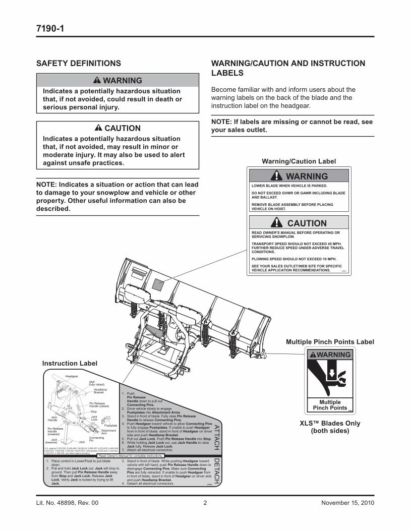
Become familiar with and inform users about the warning labels on the back of the blade and the instruction label on the headgear.
NOTE: If labels are missing or cannot be read, see your sales outlet.
Warning/Caution Label
Instruction Label
Multiple Pinch Points Label
LOWER BLADE WHEN VEHICLE IS PARKED.
DO NOT EXCEED GVWR OR GAWR INCLUDING BLADE AND BALLAST.
REMOVE BLADE ASSEMBLY BEFORE PLACING VEHICLE ON HOIST.
READ OWNER'S MANUAL BEFORE OPERATING OR SERVICING SNOWPLOW.
TRANSPORT SPEED SHOULD NOT EXCEED 45 MPH. FURTHER REDUCE SPEED UNDER ADVERSE TRAVEL CONDITIONS.
PLOWING SPEED SHOULD NOT EXCEED 10 MPH.
SEE YOUR SALES OUTLET/WEB SITE FOR SPECIFIC VEHICLE APPLICATION RECOMMENDATIONS. 59900
WARNING
CAUTION
XLS™ Blades Only(both sides)
Lit. No. 48898, Rev. 00 3 November 15, 2010
7190-1
PERSONAL SAFETY
• Remove ignition key and put the vehicle in park or in gear to prevent others from starting the vehicle during installation or service.
• Wear only snug-fi tting clothing while working on your vehicle or snowplow.
• Do not wear jewelry or a necktie, and secure long hair.
• Wear safety goggles to protect your eyes from battery acid, gasoline, dirt and dust.
• Avoid touching hot surfaces such as the engine, radiator, hoses and exhaust pipes.
• Always have a fi re extinguisher rated BC handy, for fl ammable liquids and electrical fi res.
FIRE AND EXPLOSION
Be careful when using gasoline. Do not use gasoline to clean parts. Store only in approved containers away from sources of heat or fl ame.
CELL PHONES
A driver's fi rst responsibility is the safe operation of the vehicle. The most important thing you can do to prevent a crash is to avoid distractions and pay attention to the road. Wait until it is safe to operate Mobile Communication Equipment such as cell phones or two-way radios.
VENTILATION
SAFETY PRECAUTIONS
Improper installation and operation could cause personal injury and/or equipment and property damage. Read and understand labels and the Owner's Manual before installing, operating or making adjustments.
WARNINGLower blade when vehicle is parked. Temperature changes could change hydraulic pressure, causing the blade to drop unexpectedly or damaging hydraulic components. Failure to do this could result in serious personal injury.
WARNINGRemove blade assembly before placing vehicle on hoist.
WARNINGThe driver shall keep bystanders clear of the blade when it is being raised, lowered or angled. Do not stand between the vehicle and the blade or within 8 feet of a moving blade. A moving or falling blade could cause personal injury.
WARNINGTo prevent accidental movement of the blade, always turn the control OFF whenever the snowplow is not in use. The power indicator light will turn OFF.
WARNINGDo not exceed GVWR or GAWR including the blade and ballast. The rating label is found on the driver-side vehicle door cornerpost.
WARNINGKeep hands and feet clear of the blade and A-frame when mounting or removing the snowplow. Moving or falling assemblies could cause personal injury.
WARNINGGasoline is highly fl ammable and gasoline vapor is explosive. Never smoke while working on vehicle. Keep all open fl ames away from gasoline tank and lines. Wipe up any spilled gasoline immediately.
WARNINGVehicle exhaust contains lethal fumes. Breathing these fumes, even in low concentrations, can cause death. Never operate a vehicle in an enclosed area without venting exhaust to the outside.
Lit. No. 48898, Rev. 00 4 November 15, 2010
7190-1
INSTALLATION INSTRUCTIONS
NOTE: For easier assembly and installation, vehicle and all snowplow components should be on a smooth, level, hard surface, such as concrete.
1. If the vehicle is equipped with tow hooks, remove them. Retain the tow hooks and fasteners for reinstallation if the snowplow mount is removed.
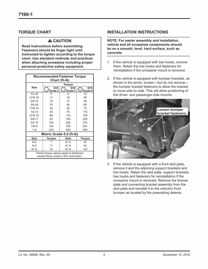
2. If the vehicle is equipped with bumper brackets, as shown in the photo, loosen—but do not remove—the bumper bracket fasteners to allow the bracket to move side-to-side. This will allow positioning of the driver- and passenger-side mounts.
3. If the vehicle is equipped with a front skid plate, remove it and the adjoining support brackets and tow hooks. Retain the skid plate, support brackets, tow hooks and fasteners for reinstallation if the snowplow mount is removed. Remove the license plate and connecting bracket assembly from the skid plate and reinstall it to the vehicle's front bumper as located by the preexisting detents.
TORQUE CHART
Recommended Fastener TorqueChart (ft-lb)
SizeTorque
SAEGrade 2
SAEGrade 5
SAEGrade 8
1/4-20 6 9 135/16-18 11 18 283/8-16 19 31 463/8-24 24 46 687/16-14 30 50 751/2-13 45 75 115
9/16-12 66 110 1655/8-11 93 150 2253/4-10 150 250 3707/8-9 150 378 5911-8 220 583 893
Metric Grade 8.8 (ft-lb)Size Torque Size TorqueM 6 7 M 12 60M 8 17 M 14 95M 10 35 M 16 155
These torque values apply to fastenersexcept those noted in the instruction.
CAUTIONRead instructions before assembling. Fasteners should be fi nger tight until instructed to tighten according to the torque chart. Use standard methods and practices when attaching snowplow including proper personal protective safety equipment.
Loosen bumper bracket fasteners.
Lit. No. 48898, Rev. 00 5 November 15, 2010
7190-1
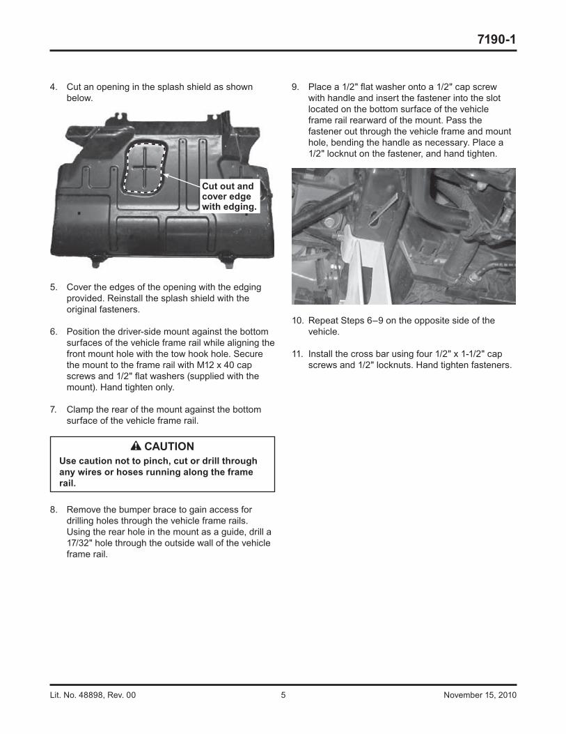
4. Cut an opening in the splash shield as shown below.
5. Cover the edges of the opening with the edging provided. Reinstall the splash shield with the original fasteners.
6. Position the driver-side mount against the bottom surfaces of the vehicle frame rail while aligning the front mount hole with the tow hook hole. Secure the mount to the frame rail with M12 x 40 cap screws and 1/2" fl at washers (supplied with the mount). Hand tighten only.
7. Clamp the rear of the mount against the bottom surface of the vehicle frame rail.
8. Remove the bumper brace to gain access for drilling holes through the vehicle frame rails. Using the rear hole in the mount as a guide, drill a 17/32" hole through the outside wall of the vehicle frame rail.
9. Place a 1/2" fl at washer onto a 1/2" cap screw with handle and insert the fastener into the slot located on the bottom surface of the vehicle frame rail rearward of the mount. Pass the fastener out through the vehicle frame and mount hole, bending the handle as necessary. Place a 1/2" locknut on the fastener, and hand tighten.
10. Repeat Steps 6–9 on the opposite side of the vehicle.
11. Install the cross bar using four 1/2" x 1-1/2" cap screws and 1/2" locknuts. Hand tighten fasteners.
Cut out and cover edge with edging.
CAUTIONUse caution not to pinch, cut or drill through any wires or hoses running along the frame rail.
Lit. No. 48898, Rev. 00 6 November 15, 2010
7190-1
Fisher Engineering reserves the right under its product improvement policy to change construction or design details and furnish equipment when so altered without reference to illustrations or specifi cations used. Fisher Engineering or the vehicle manufacturer may require or recommend optional equipment for snow removal. Do not exceed vehicle ratings with a snowplow. Fisher Engineering offers a limited warranty for all snowplows and accessories. See separately printed page for this important information. The following are registered (®) trademarks of Douglas Dynamics, L.L.C.: FISHER®, Minute Mount® 2.
Printed in U.S.A.
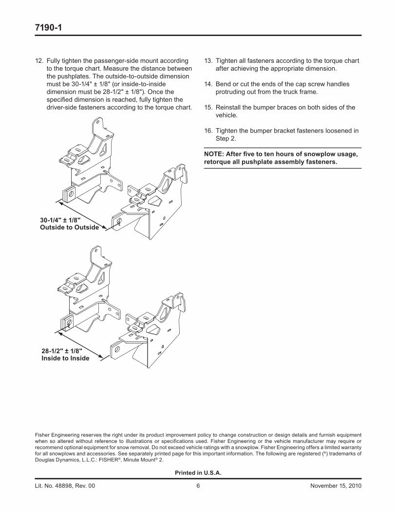
12. Fully tighten the passenger-side mount according to the torque chart. Measure the distance between the pushplates. The outside-to-outside dimension must be 30-1/4" ± 1/8" (or inside-to-inside dimension must be 28-1/2" ± 1/8"). Once the specifi ed dimension is reached, fully tighten the driver-side fasteners according to the torque chart.
30-1/4" ± 1/8"Outside to Outside
28-1/2" ± 1/8"Inside to Inside
13. Tighten all fasteners according to the torque chart after achieving the appropriate dimension.
14. Bend or cut the ends of the cap screw handles protruding out from the truck frame.
15. Reinstall the bumper braces on both sides of the vehicle.
16. Tighten the bumper bracket fasteners loosened in Step 2.
NOTE: After fi ve to ten hours of snowplow usage, retorque all pushplate assembly fasteners.