Embed Size (px)
Citation preview

II. The Damage and Accident Responses at the Fukushima Dai-ichi NPS and the Fukushima
Dai-ni NPS
1. The Damage at the Major Systems and Facilities of Units 1 to 3 of the Fukushima Dai-ichi
NPS
(1) Introduction
Chapter II. 3. of the Interim Report gave an outline of the damage to the systems and
facilities having functions important for the control of the plant toward a cold shutdown.
After the Interim Report was published, the Investigation Committee thoroughly reviewed
the objective data of each Unit of the Fukushima Dai-ichi Nuclear Power Station (“Fukushima
Dai-ichi NPS”), including plant related parameters, alarm typer outputs, Transient Analysis
Recording System data, recorder charts, shift operators’ logbooks and memos. The committee
investigated further through such means as interviews with relevant individuals including those
at Tokyo Electric Power Company (“TEPCO”), plant manufacturers and Japan Nuclear Energy
Safety Organization (“JNES,” an independent administrative corporation). Based on the facts
revealed in these investigations, the Investigation Committee conducted its reviews from a
dynamic perspective such as reviews in terms of the occurrence, extent and time of functional
failures with the major systems and facilities, particularly for Units 1 through 3. The major
systems and facilities investigated include the Reactor Pressure Vessel (hereinafter “RPV”) and
the Primary Containment Vessel (hereinafter “PCV”) as well as cooling and water injection
systems such as the Isolation Condenser (“IC”), the Reactor Core Isolation Cooling system
(“RCIC”) and the High Pressure Coolant Injection system (“HPCI”).
As the investigation was a huge undertaking that covered a wide range of areas, details are
described in Attachment II-1-1. The sections below first discuss the mechanisms of the
instrumentation that is essential to the investigation into the damage of the major systems and
facilities, followed by a comprehensive general description on analyses concerning reactor core
conditions and recapitulative descriptions on conclusions regarding the damage at the major
systems and facilities of each Unit.
The evidence for each conclusion is provided in detail in Attachment II-1-1. Refer to that as
necessary.
-7-

(2) Major instrumentation mechanisms and related discussions
a. Significance
In verifying the integrity of the RPV and PCV, the relevant parameters recorded at each Unit,
such as the reactor water level, reactor pressure, Drywell (“D/W”) pressure, Suppression
Chamber (“S/C”) pressure are vital for the assessment of the conditions of each Unit at the time
of the accident.
These parameters are a collection of the measurements of each instrument at a certain point
in time. In the event that the instruments did not function properly such that they showed
incorrect measurements and if such measurements were used as absolutely correct values, there
would be a chance that the conditions of each Unit at the time of the accident might be
misinterpreted or that accurate integrity verification of the RPV and PCV would not be possible.
Conversely, throwing out measurements without any significant reason for false indications
would be equivalent to throwing away the few important clues available for the integrity
verification of the RPV and PCV.
Hence, knowledge of the mechanism of each instrument and an understanding of what
conditions could cause what kind of false measurements and/or erroneous indications are major
prerequisites for taking correct measurements of the plant related parameters and for integrity
verification of the RPV and PCV.
Beyond the above, deeper understanding on this point may lead to clues to identify the causes
of false measurements and/or erroneous indications estimated from the trends in the relevant
parameters. Particularly in the event that these causes related to the conditions of the RPV or
PCV, identifying such causes acts as extremely important clues in determining the conditions of
the RPV and PCV and hence in assessing their integrity.
Thus, there is significance in discussing the mechanisms of major instrumentation and the
causes behind any false measurements and/or erroneous indications.
b. Mechanism of major instrumentation
(a) Reactor pressure indicators
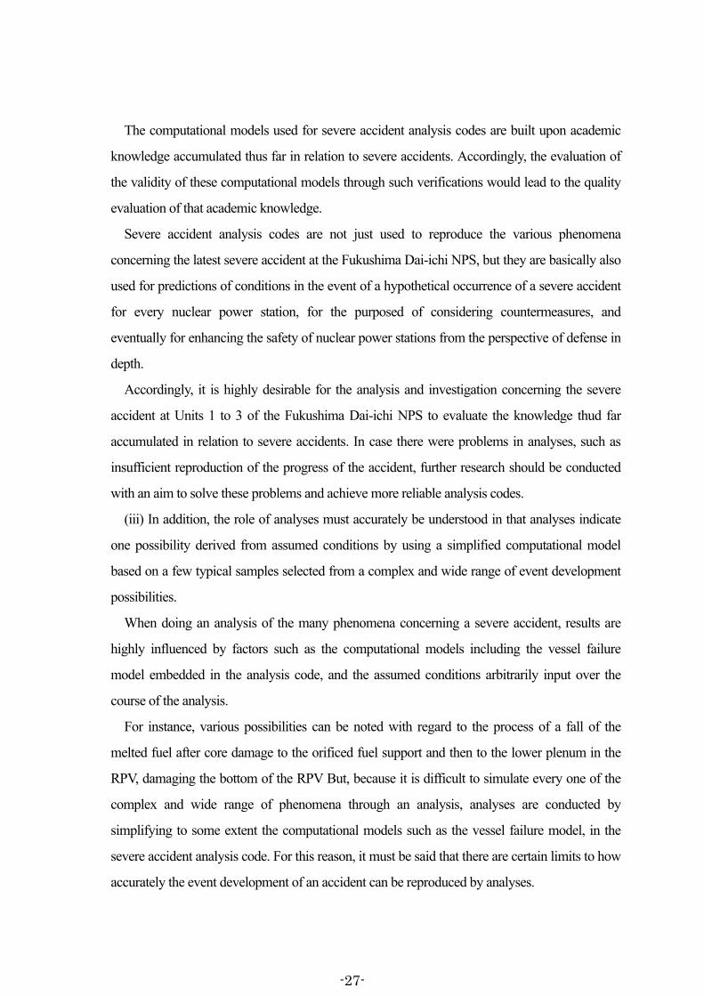
(i) Reactor pressure indicators provide reactor pressure indications derived from the water
pressure applied, through the reference leg and its associated instrument line (hereinafter
-8-

“reference leg line”) installed outside the RPV (but within the PCV) via the RPV penetrations,
on the isolation diaphragm within the pressure transmitter installed at the instrumentation rack
inside the reactor building (“R/B”), reduced by the water head1 between the water level of the
reference leg (hereinafter “reference level”) and the pressure transmitter. As the reactor pressure
indicator measures gage pressure (the difference between the absolute pressure and atmospheric
pressure), the pressure measured in the pressure transmitter and used in conversion is actually a
value of the pressure in the reference leg line (absolute pressure) less the atmospheric pressure
(see Figures II-1-1 and 2).
圧力伝送器
基準面器
原子炉格納容器
図Ⅱ-1-1 原子炉圧力計の概要
Reference leg
PCV
Pressure transmitter
Fig. II-1-1 Outline of the reactor pressure indicator
大気圧側 基準面器側配管
半導体圧力センサ
封入液
隔液ダイアフラム隔液
ダイアフラム
図Ⅱ-1-2 圧力伝送器
株式会社日立製作所のカタログを基に作成
Atmosphere side
Reference leg line side
Semiconductor pressure sensor
Sealant
Isolation diaphragm
Based on a Hitachi, Ltd. brochure
Fig. II-1-2 Pressure transmitter
Isolation diaphragm
The above reference leg is shared with the reactor water level indicator. For Units 1 to 3, the
instrument line is installed at the elevation of slightly above TAF+5,000mm (TAF : Top of
Active Fuel) in the RPV, to take in the RPV conditions to the reference leg. Consequently the
water pressure applied on the isolation diaphragm within the pressure transmitter varies
according to the reactor pressure.
(ii) And, in the pressure transmitter, the water pressure applied on the isolation diaphragm
through the reference leg line from the reference leg less the atmospheric pressure is converted
1 The water head between the reference leg and the pressure transmitter is dependent on the installation conditions
of the reference leg line and the pressure transmitter. Among the reactor pressure indicators used during the responses to the accident, those for Units 1 and 3 have such water head difference of 90kPa abs and for Unit 2 of 97kPa abs.
-9-
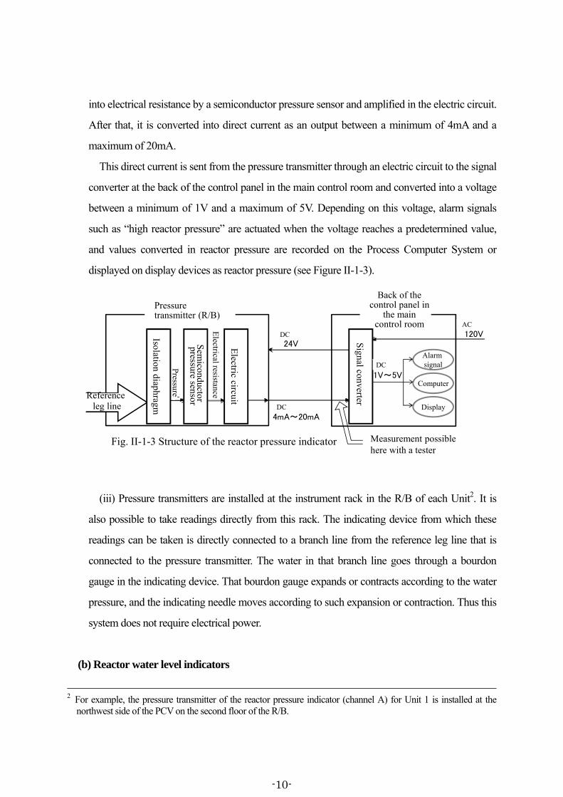
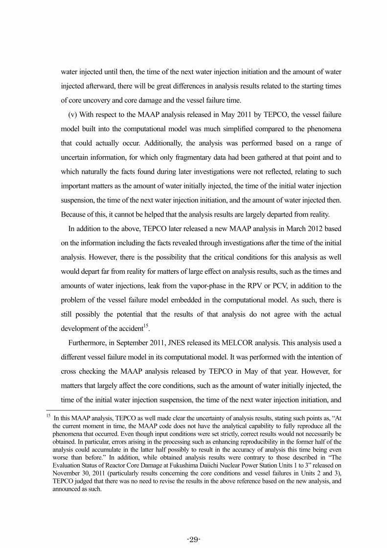
into electrical resistance by a semiconductor pressure sensor and amplified in the electric circuit.
After that, it is converted into direct current as an output between a minimum of 4mA and a
maximum of 20mA.
This direct current is sent from the pressure transmitter through an electric circuit to the signal
converter at the back of the control panel in the main control room and converted into a voltage
between a minimum of 1V and a maximum of 5V. Depending on this voltage, alarm signals
such as “high reactor pressure” are actuated when the voltage reaches a predetermined value,
and values converted in reactor pressure are recorded on the Process Computer System or
displayed on display devices as reactor pressure (see Figure II-1-3).
圧力伝送器(R/B)
隔液ダイアフラム
半導体圧力センサ
電気回路
圧
力
直流
4mA~20mA
電気抵抗
基準面器側配管からの水圧
直流
24V
制御盤(裏)(中央制御室)
信号変換処理部
交流
120V
テスターによる計測も可能
表示器
警報信号
計算機
直流
1V~5V
図Ⅱ-1-3 原子炉圧力計の構成
Pressure transmitter (R/B)
Back of the control panel in
the main control room
Measurement possible here with a tester
Fig. II-1-3 Structure of the reactor pressure indicator
DC
DC
DC
Alarm signal
Computer
Display
AC
Isolation diaphragm
Sem
iconductorpressure sensor
Pressure
Electrical resistance
Electric circuit
Signal converterReference
leg line
(iii) Pressure transmitters are installed at the instrument rack in the R/B of each Unit2. It is
also possible to take readings directly from this rack. The indicating device from which these
readings can be taken is directly connected to a branch line from the reference leg line that is
connected to the pressure transmitter. The water in that branch line goes through a bourdon
gauge in the indicating device. That bourdon gauge expands or contracts according to the water
pressure, and the indicating needle moves according to such expansion or contraction. Thus this
system does not require electrical power.
(b) Reactor water level indicators
2 For example, the pressure transmitter of the reactor pressure indicator (channel A) for Unit 1 is installed at the
northwest side of the PCV on the second floor of the R/B.
-10-
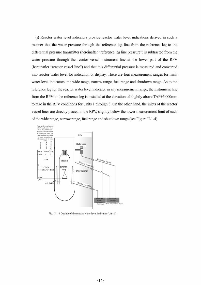
(i) Reactor water level indicators provide reactor water level indications derived in such a
manner that the water pressure through the reference leg line from the reference leg to the
differential pressure transmitter (hereinafter “reference leg line pressure”) is subtracted from the
water pressure through the reactor vessel instrument line at the lower part of the RPV
(hereinafter “reactor vessel line”) and that this differential pressure is measured and converted
into reactor water level for indication or display. There are four measurement ranges for main
water level indicators: the wide range, narrow range, fuel range and shutdown range. As to the
reference leg for the reactor water level indicator in any measurement range, the instrument line
from the RPV to the reference leg is installed at the elevation of slightly above TAF+5,000mm
to take in the RPV conditions for Units 1 through 3. On the other hand, the inlets of the reactor
vessel lines are directly placed in the RPV, slightly below the lower measurement limit of each
of the wide range, narrow range, fuel range and shutdown range (see Figure II-1-4).
(燃料域) (広帯域・狭帯域)
差圧伝送器 差圧伝送器
狭帯域
広帯域
燃料域
+1,500+1,500
-1,500
0 0+3,430
+5,000
-3,000(BAF)
0TAF(有効燃料頂部)
基準面器
原子炉格納容器
炉心
ジェットポンプ
ダウンカマ
シュラウド
○表示単位はミリメートル(1号機は、他号機と異なり、原子炉水位を表す単位は㎝であるが、他号機との比較を容易にするため、㎜換算とした。)
図Ⅱ-1-4 原子炉水位計の概要(1 号機)
PCV
Reference leg
Fig. II-1-4 Outline of the reactor water level indicator (Unit 1)
(Fuel range) (Wide range/Narrow range)
Differential pressure
transmitter
Differential pressure
transmitter
Jet pump
Shroud
Reactor core
Wide range
Narrow
range
Fuel range
Water levels in millimeters (Differing from the other Units, the Unit 1 reactor water level was indicated in centimeters, which has therefore been converted for easier comparison to
millimeters as in the other Units).
(TAF)Top of Active Fuel Downcomer
-11-

狭帯域
広帯域
燃料域
+1,500+1,500
-3,900(3号機)-4,000(2号機)
0 0+4,170
+5,000
-3,700(BAF)
0TAF(有効燃料頂部)
(燃料域) (広帯域)
差圧伝送器
(狭帯域)
(表示単位はミリメートル)
差圧伝送器 差圧伝送器
シュラウド
ダウンカマ
ジェットポンプ
炉心
基準面器
原子炉格納容器
図Ⅱ-1-5 原子炉水位計の概要(2 号機及び 3 号機)
Water levels in millimeters
Fig. II-1-5 Outline of the reactor water level indicator (Units 2 and 3)
PCV
Reference leg
Jet pump
Shroud
Downcomer
Reactor core
(Fuel range) (Wide range) (Narrow range)
Differential pressure
transmitter
Differential pressure
transmitter
Differential pressure
transmitter
Wide range
Narrow
range
Fuel range
(TAF) Top of Active Fuel
(Unit 3)
(Unit 4)
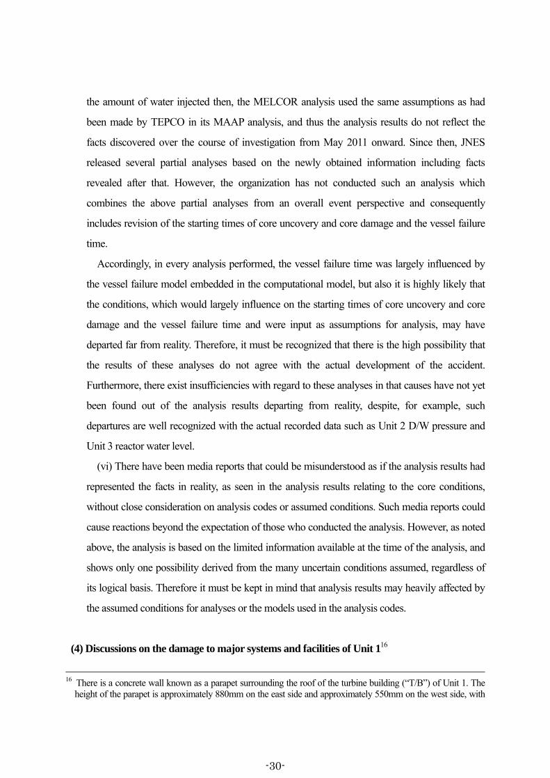
Among the reactor water level indicators of different measurement ranges, the fuel range
water level indicator measures reactor water level in the relatively lower range, where the
influence of the reactor internals would result in different water levels in the shroud containing
the fuel and in the downcomer outside the
shroud, respectively. Accordingly in order for
the fuel range water level indicator to
monitor the occurrence and extent of fuel
uncovery to the extent possible, the inlet of
the reactor vessel line in the RPV is placed in
the jet pump 3 , where water level
measurement is relatively susceptible to
water level in the shroud and perceived to
provide water level indications closer to the
actual one that counts apparent level increase
caused by boiling in the shroud. Also, the
3 Conversely, the inlets of the reactor vessel lines are placed in the downcomer in the RPV for the reactor water level
indicators of wide range, narrow range and shutdown range.
気水分離器
シュラウド
ジェットポンプ燃料棒
制御棒
蒸気
水
ダウンカマ
下部プレナム
図Ⅱ-1-6 原子炉圧力容器(シュラウド、ダウンカマ)Fig. II-1-6 RPV (Shroud, Downcomer)
Control rod
Jet pump
Downcomer
Steam separator
Fuel rod
Shroud
Water
Steam
Lower plenum
-12-
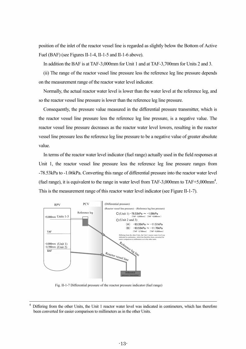
position of the inlet of the reactor vessel line is regarded as slightly below the Bottom of Active
Fuel (BAF) (see Figures II-1-4, II-1-5 and II-1-6 above).
In addition the BAF is at TAF-3,000mm for Unit 1 and at TAF-3,700mm for Units 2 and 3.
(ii) The range of the reactor vessel line pressure less the reference leg line pressure depends
on the measurement range of the reactor water level indicator.
Normally, the actual reactor water level is lower than the water level at the reference leg, and
so the reactor vessel line pressure is lower than the reference leg line pressure.
Consequently, the pressure value measured in the differential pressure transmitter, which is
the reactor vessel line pressure less the reference leg line pressure, is a negative value. The
reactor vessel line pressure decreases as the reactor water level lowers, resulting in the reactor
vessel line pressure less the reference leg line pressure to be a negative value of greater absolute
value.
In terms of the reactor water level indicator (fuel range) actually used in the field responses at
Unit 1, the reactor vessel line pressure less the reference leg line pressure ranges from
-78.53kPa to -1.06kPa. Converting this range of differential pressure into the reactor water level
(fuel range), it is equivalent to the range in water level from TAF-3,000mm to TAF+5,000mm4.
This is the measurement range of this reactor water level indicator (see Figure II-1-7).
基準面器
圧力容器原子炉格納容器
差圧伝送器
○1号機 -78.53kPa ~ -1.06kPa(TAF -3,000mm) (TAF +5,000mm )+5,000mm (1~3号機)
TAF
-3,000mm (1号機)-3,700mm (2、3号機)
BAF
○2号機及び3号機
(A) -93.35kPa ~ -11.51kPa
(B) -93.53kPa ~ -11.70kPa(TAF -3,700mm) (TAF +5,000mm)
(1号機は、他号機と異なり、原子炉水位を表す単位はcmであるが、他号機との比較を容易にするため、mm換算とした。)
〈差圧〉(炉側配管圧力)-(基準面器側配管圧力)
図Ⅱ-1-7 原子炉水位計(燃料域)の差圧 Fig. II-1-7 Differential pressure of the reactor pressure indicator (fuel range)
Differing from the other Units, the Unit 1 reactor water level was indicated in centimeters, which has therefore been converted for easier comparison to millimeters as in the other units.
text
(Differential pressure)RPV PCV
Reference leg
Differential pressure transmitter
(Unit 1)(Unit 2)
Units 1-3(Unit 2 and 3)
(Unit 1)
(Reactor vessel line pressure) – (Reference leg line pressure)
4 Differing from the other Units, the Unit 1 reactor water level was indicated in centimeters, which has therefore
been converted for easier comparison to millimeters as in the other Units.
-13-
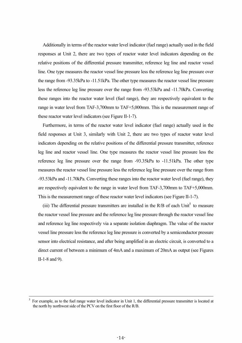
Additionally in terms of the reactor water level indicator (fuel range) actually used in the field
responses at Unit 2, there are two types of reactor water level indicators depending on the
relative positions of the differential pressure transmitter, reference leg line and reactor vessel
line. One type measures the reactor vessel line pressure less the reference leg line pressure over
the range from -93.35kPa to -11.51kPa. The other type measures the reactor vessel line pressure
less the reference leg line pressure over the range from -93.53kPa and -11.70kPa. Converting
these ranges into the reactor water level (fuel range), they are respectively equivalent to the
range in water level from TAF-3,700mm to TAF+5,000mm. This is the measurement range of
these reactor water level indicators (see Figure II-1-7).
Furthermore, in terms of the reactor water level indicator (fuel range) actually used in the
field responses at Unit 3, similarly with Unit 2, there are two types of reactor water level
indicators depending on the relative positions of the differential pressure transmitter, reference
leg line and reactor vessel line. One type measures the reactor vessel line pressure less the
reference leg line pressure over the range from -93.35kPa to -11.51kPa. The other type
measures the reactor vessel line pressure less the reference leg line pressure over the range from
-93.53kPa and -11.70kPa. Converting these ranges into the reactor water level (fuel range), they
are respectively equivalent to the range in water level from TAF-3,700mm to TAF+5,000mm.
This is the measurement range of these reactor water level indicators (see Figure II-1-7).
(iii) The differential pressure transmitters are installed in the R/B of each Unit5 to measure
the reactor vessel line pressure and the reference leg line pressure through the reactor vessel line
and reference leg line respectively via a separate isolation diaphragm. The value of the reactor
vessel line pressure less the reference leg line pressure is converted by a semiconductor pressure
sensor into electrical resistance, and after being amplified in an electric circuit, is converted to a
direct current of between a minimum of 4mA and a maximum of 20mA as output (see Figures
II-1-8 and 9).
5 For example, as to the fuel range water level indicator in Unit 1, the differential pressure transmitter is located at
the north by northwest side of the PCV on the first floor of the R/B.
-14-

半導体圧力センサ
端子箱
電気回路
センターダイアフラム
隔液ダイアフラム
図Ⅱ-1-8 差圧伝送器の形状及び内部構造
株式会社日立製作所のカタログを基に作成
Terminal box
Fig. II-1-8 Shape and inner structure of the differential pressure transmitter
Based on a Hitachi Ltd. brochure
Isolation diaphragm
Center DiaphragmElectric circuit
Semiconductor pressure sensor
基準面器側配管炉側配管
封入液
隔液ダイアフラム
隔液ダイアフラム
センターダイアフラム(過圧保護機能を有する)
半導体圧力センサ
図Ⅱ-1-9 差圧伝送器
株式会社日立製作所のカタログを基に作成 Based on a Hitachi Ltd. brochure
Reference leg line
Sealant
Semiconductor pressure sensor
Reactor vessel line
Isolation diaphragm
Fig. II-1-9 Differential pressure transmitter
Center diaphragm(with over
pressure protection)
Isolation diaphragm
This direct current is sent from the differential pressure transmitter to the signal converter at
the back of the control panel in the main control room and converted into a voltage between a
minimum of 1V and a maximum of 5V. This in turn is converted to the reactor water level for
indications and displays (see Figure II-1-10).
差圧伝送器(R/B)
半導体圧力センサ
電気回路
差
圧
直流
4mA~20mA
電気抵抗
基準面器側配管からの水圧
直流
24V
隔液ダイアフラム
炉側配管からの水圧
制御盤(裏)(中央制御室)
信号変換処理部
交流
120V
テスターによる計測も可能
表示器
警報信号
計算機
直流
1V~5V
隔液ダイアフラム
図Ⅱ-1-10 原子炉水位計の構成
Differential pressure transmitter (R/B)
Fig. II-1-10 Structure of the reactor water level indicator
Measurement possible here
with a tester
DC
DC
DC
AC
Computer
Display
Isolation diaphragm
Differential pressure
Sem
iconductorpressure sensor
Electrical resistance
Electric circuit
Signal converter
Isolation diaphragm
Water pressure from the reference leg line
Water pressure from the reactor vessel line
Back of the control panel in the main control room
Alarm signal
(c) D/W pressure gauge
D/W pressure indicators measure via the isolation diaphragm located in the pressure
-15-

transmitter6 the pressure in the D/W directly propagated to the transmitter through the
instrument line from the detection point within the PCV (see Figure II-1-11).
Within the pressure transmitter this
measurement is converted into electrical
resistance by a semiconductor pressure
sensor and amplified. It is then converted and
output as a direct current of between a
minimum of 4mA and a maximum of 20mA
and sent from the pressure transmitter to the
signal converter at the back of the control
panel in the main control room. After that, it
is converted into a voltage of between a
minimum of 1V and a maximum of 5V,
which is then converted into D/W pressure. The D/W pressure signal is used for system
initiation including alarm actuation signals such as “high D/W pressure” and for displays by the
Process Computer System and other display devices.
In addition, there is also a D/W pressure indicator installed at the instrument rack in the R/B
of each Unit, where it is possible to take direct readings without any electrical power. This
indicating device is directly connected to a branch line from the instrument line that is
connected to the pressure transmitter. The atmosphere inside the D/W enters the bourdon gauge
in the indicating device through the instrument line. The needle on the indicating device moves
according to the expansion or contraction of the bourdon gauge. There is thus no need for
electrical power.
(d) S/C pressure indicators
6 The location of installation is at the instrument rack in the R/B of each Unit. This is installed in an instrumentation
rack in each Unit’s R/B.
格納容器(D/W)
圧力抑制室(S/C)
圧力伝送器
D/W圧力
原子炉圧力容器
図Ⅱ-1-11 D/W 圧力計
D/W
S/C D/W pressure
RPV
Pressure transmitter
Fig. II-1-11 D/W pressure indicator
-16-

There are two types of S/C
pressure indicators that require
electrical power. One type
processes water pressure
propagated through the reference
leg line to the pressure transmitter
from the reference leg connected to
the vapor phase of the S/C. After
the signal processing including
conversion into electrical
resistance in much the same way
as the reactor pressure indicators. The measurement is readable on the instrumentation in the
main control room. The other type processes atmospheric pressure in the vapor phase of the S/C
transmitted through the instrument line connected to the vapor phase of the S/C. After the signal
processing including conversion into electrical resistance in much the same way as D/W
pressure indicators, the measurements are also readable on the instrumentation in the main
control room. The difference between the two is that one uses the reference leg to measure
water pressure while the other directly measures atmospheric pressure in the vapor-phase of the
S/C (see Figure II-1-12).
c. Instrumentation power supplies
In terms of the power supply for the instruments detailed in subsection (2) b above, 24V
direct current (DC) power supplies are supposed to apply, converted from alternating current
(AC) power such as the 120V AC power distribution panel for the Reactor Protection System.
In other words, if 24V DC power is available7, it can power the pressure transmitters and
differential pressure transmitters. This power is used also to convert into electrical resistance
and amplify the water pressure and/or atmospheric pressure measured in the pressure
transmitter and/or differential pressure transmitter, enabling such signals to be sent to their
7 Because total AC power was lost, in the response to the accident, unlike under normal circumstances, multiple
batteries were connected in series to supply 24V DC power.
格納容器(D/W)
圧力抑制室(S/C)
原子炉圧力容器
S/C圧力
基準面器
圧力伝送器 圧力伝送器
図Ⅱ-1-12 S/C 圧力計 S/C pressure
D/W
RPV
Reference leg
Pressure transmitter
Pressure transmitter
Fig. II-1-12 S/C pressure indicator
S/C
-17-

destinations including the signal converter located on the back of the control panel in the main
control room.
While there are instruments that need only 24V DC power to show readings, there are also
those that additionally require 120V AC power. The latter instruments can not indicate readings
without 120V AC power, yet it is possible to take readings as long as 24V DC power is
available. Since with 24V DC power the pressure transmitter and differential pressure
transmitter can measure the pressure and send the corresponding signal to the signal converter,
it is possible to read with a tester the signals in current or voltage at the signal converter and
separately to convert them into plant parameters in their proper units.
d. Causes of false measurements and/or erroneous indications
(i) For the instruments discussed in subsection (2) b above, the pressure transmitters and
differential pressure transmitters have passed the long-term validation tests that consider
long-term thermal and mechanical aging degradation and ambient conditions at an accident.
Namely it is confirmed that no anomaly was found in the hydrostatic test, insulation resistance
test and input-output test conducted after placing the pressure transmitters or differential
pressure transmitters for 38 days in the vapor environment with a maximum temperature of
100°C and a maximum pressure of 1.8kPA gage8. Since it is highly unlikely that the inside of
the R/B was exposed to such an atmosphere at the time of the accident, it is equally unlikely
that malfunctions in the pressure transmitters or differential pressure transmitters may have
caused false measurements and/or erroneous indications.
On the other hand, even if there was no anomaly with the pressure transmitters or differential
pressure transmitters, false measurements and/or erroneous indications could occur in case the
conditions of the RPV or PCV are not accurately reflected on the pressure applied to the
isolation diaphragm in the pressure transmitter or differential pressure transmitter from the RPV
or PCV through the instrument line. The following considers such a case.
(ii) First, reactor pressure indicators measure water pressure applied to the isolation
diaphragm located inside the pressure transmitter from the reference leg through the reference
8 Note that the tests are for pressure transmitters or differential pressure transmitters but not for sensors which may
be exposed to a more severe environment.
-18-

leg line. Reactor pressure is derived from this pressure less the reference water head.
As long as the water level in the reference leg is maintained at the level of the reference water
head, reactor pressure is correctly measured. However, if the water level lowers in the reference
leg or even drops down into the reference leg line, the actual water head becomes less than the
reference water head that is based on the water level maintained at the reference level.
Accordingly the difference between the actual and reference water heads will produce an error
in the measured reactor pressure and result in the reactor pressure being indicated less than
actually is.
The error caused by a water level drop in the reference leg is no greater than the water head
between the reference level and the pressure transmitter. As to the reactor pressure indicators
utilized in the responses to the accident, such errors should be up to 90kPa for Units 1 and 3,
and up to 97kPa for Unit 29. It is highly unlikely, however, that ambient temperature around the
reference leg line continues to stay over 100°C even when the water level in the reference leg
falls down to such a level as to reach outside the PCV. Therefore, it is natural to consider that
the water level fall in the reference leg line will not continue in such a case and so errors may be
even smaller.
(iii) Reactor water level indicators measure the reactor vessel line pressure less the reference
leg line pressure and convert the measured differential pressure to reactor water level, on the
condition that the water level in the reference leg is maintained at the level of the reference
water head and that the reactor water level stays above the inlet elevation of the reactor vessel
line.
Accordingly, reactor water level indicators (fuel range) measure, differently from reactor
pressure indicators, differential pressure within the measurable range in the differential pressure
transmitter of about 80kPa10. Differential pressure in this measurable range is converted to fuel
range water level with a corresponding range in fuel range water level of 8,000mm for Unit 1
and of 8,700mm for Units 2 and 3, respectively. Consequently an error of only 10kPa in
differential pressure could lead to an error of 1,000mm or more in reactor water level indication.
9 See Attachment II-1-2. 10 As noted in b (b) (ii), the reactor water level indicator (fuel range) has the measureable range in the differential
pressure transmitter of about 80kPa, which is the difference between the upper and lower limits, and converts the differential pressure in this range into reactor water levels.
-19-
The following discusses causes of errors due to the mechanism of reactor water level
indicators11.
First, it was found afterward that the water level in the reference leg and reference leg line
had been considerably lower than the original reference level when TEPCO had filled the
reference legs with water for Units 1 and 2. Water level decrease in the reference leg or further
decrease down to the reference leg line could lead to smaller reference leg line pressure that
should otherwise remain constant.
Consequently smaller differential pressure between the reactor vessel line pressure and
reference leg line pressure would result in a measurement in the differential pressure transmitter
being a negative value of smaller absolute value, compared with the case that water level is
maintained at the reference level. Thus the reactor water level indicator provides a false
measurement and erroneous indication as being higher than it actually is.
For example, it is assumed that the reference leg line pressure, which should originally be
90kPa abs, fell to 80kPa abs due to a water level fall in the reference leg, and that the measured
reactor vessel line pressure was 60kPa abs. Then the differential pressure transmitter would
provide -20kPa as the reactor vessel line pressure less the reference leg line pressure due to a
water level fall in the reference leg, instead of providing -30kPa if water level were maintained
at the original reference level. Consequently the reactor water level indicator would provide an
erroneous indication of higher reactor water level, resulted from the conversion into water level
of the above mentioned differential pressure of -20kPA that has smaller absolute value than
-30kPa, which value should have been used instead if the original reference level were
maintained in the reference leg.
Furthermore, if the reactor water level fell below the inlet elevation of the reactor vessel line,
a fall or rise of reactor water level below this elevation would not influence on the pressure
applied on the isolation diaphragm in the differential pressure transmitter through the reactor
vessel line. In this case, because the differential pressure transmitter measures only the
difference in water heads between the water levels in the reactor vessel line and reference leg
line, the differential pressure completely independent of actual reactor water level behavior
would be used for conversion into water level and for indications. 11 See Attachment II-1-3.
-20-
Beyond that, if the above two phenomena occurred at once, the water levels would fall in the
reference leg line and the reactor vessel line. Water evaporation in the both lines, however,
would potentially not continue after the water levels reaching close to the exterior wall of the
PCV, where the both lines would be exposed to sufficiently low ambient temperature and less
influenced by the conditions inside the RPV.
If this is the case, the water levels in the both lines would hardly change after reaching the
PCV wall, accordingly so would be the water pressures applied through both lines on the
isolation diaphragms in the differential pressure transmitter. Consequently, such phenomena
could potentially occur as reactor water level indications would remain unchanged over a long
period of time, since these differential pressures are converted to reactor water level.
As to the plant related parameters of each Unit during the accident, several cases were
identified where reactor water level indications had remained unchanged over a long period of
time. This implies that there would be the possibility of the occurrence of the above phenomena
and that reactor water level might have already been below BAF during these time periods.
(iv) As for reactor water level indicators, these phenomena could possibly occur in the
environments where the conditions inside the RPV and the reference leg, the former influencing
the latter, are helpful for water evaporation. In other words, these phenomena could occur in the
event that the saturation temperature of water lowers due to lower reactor pressure by
depressurization, or in the event that the PCV temperature rises around the instrument lines.
Specific examples include such events that rapid depressurization was conducted by opening
the main steam Safety Relief Valve (SRV) or that core damage started. On the other hand, it is
difficult to say that during the time after the earthquake but before the arrival of the tsunami
rapid reactor depressurization or a rapid rise in PCV temperature resulted in the water in the
reference leg line being saturated. Consequently, it is believed that during such time the
instruments for major parameters such as reactor pressures, reactor water levels, D/W pressures
and S/C pressures were in the environment where an event like a reference leg water level fall
caused errors in indications.
Accordingly, there is no specific reason found to doubt the reliability of data such as the
record charts for measurements from such major instruments for the period after the earthquake
but before the tsunami.
-21-

Conversely, in Units 1 to 3, there may have been false measurements and/or erroneous
indications with reactor pressure indicators or reactor water level indicators caused by a fall in
reference leg water level, if any of these events had occurred, i.e. if the progress of conditions
had resulted in core damage to begin, if operations such as rapid depressurization by opening
the SRV had led to lower RPV pressure, or if temperature had been high in the PCV. In such a
case, since the reactor pressure indicator simply measures and converts into reactor pressure the
reference leg line pressure less the reference water head, errors in indications would be
downward and limited to an extent to 90kPa at the maximum in Units 1 and 3 and 97kPa at the
maximum in Unit 2. Conversely, since the reactor water level indicator measures and converts
into reactor water level the reactor vessel line pressure less the reference leg line pressure, errors
in indications due to a reference level fall may reach so large extent that water level would be
indicated several meters higher than actually is.
In the event that the reactor water level fell further down below the inlet elevation of the
reactor vessel line, since the reactor water level indicator measures and converts into reactor
water level the reactor vessel line pressure less the reference leg line pressure, i.e. the difference
between water heads in these lines to the differential pressure transmitter, the indicated values
would not reflect reactor water level at all. Thus it would not be possible to grasp the actual
reactor water level from reactor water level indications.
Moreover, in case the water level continued to fall, due to evaporation in these lines, down to
around the PCV penetrations where evaporation halted, there would no longer be any further
changes seen at the pressure transmitter in the measurement of the reactor vessel line pressure
less the reference leg line pressure. As such, there could be phenomena where reactor water
level indications would stay flat.
In other words, first, Table II-1-1 shows the elevations of the PCV penetrations of the
reference leg line and reactor vessel line for the fuel range reactor water level indicators for
Units 1 through 3.
-22-
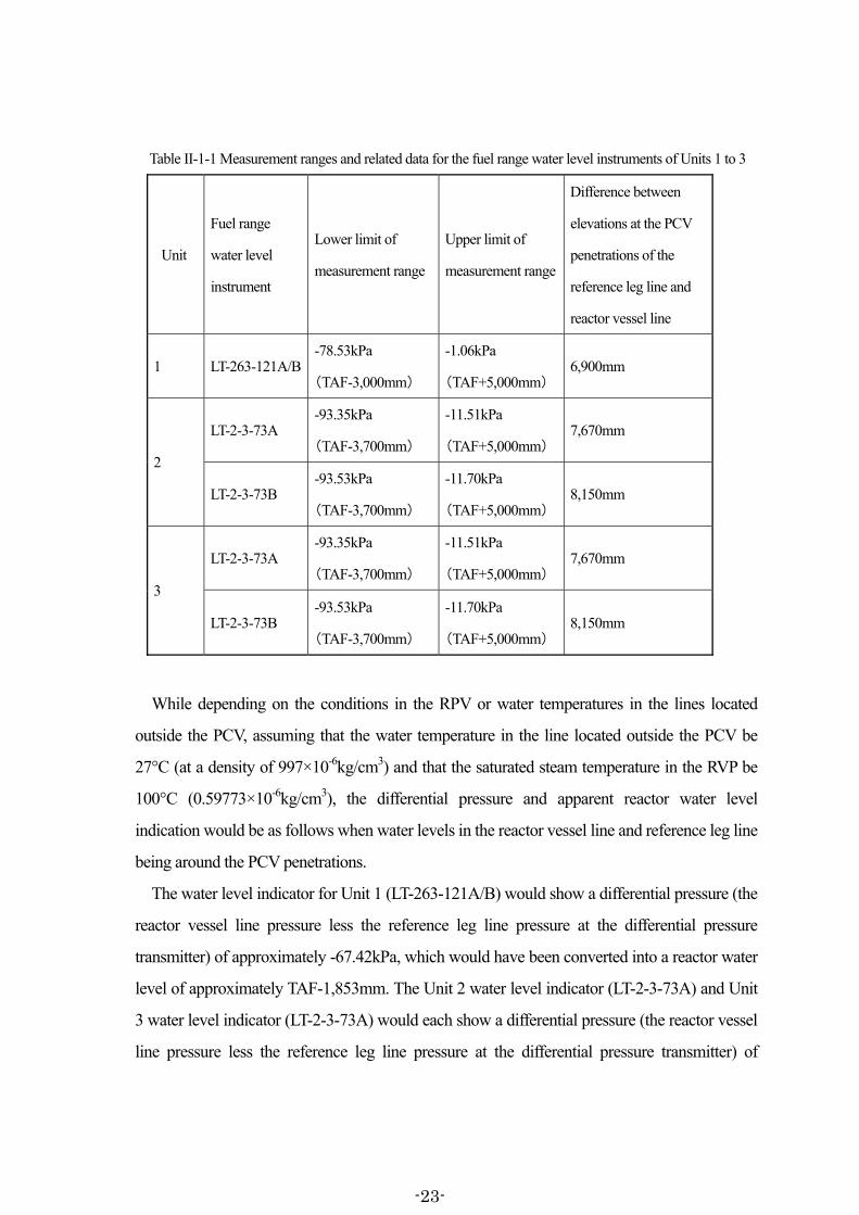
Table II-1-1 Measurement ranges and related data for the fuel range water level instruments of Units 1 to 3
Unit
Fuel range
water level
instrument
Lower limit of
measurement range
Upper limit of
measurement range
Difference between
elevations at the PCV
penetrations of the
reference leg line and
reactor vessel line
1 LT-263-121A/B -78.53kPa
(TAF-3,000mm)
-1.06kPa
(TAF+5,000mm) 6,900mm
2
LT-2-3-73A -93.35kPa
(TAF-3,700mm)
-11.51kPa
(TAF+5,000mm) 7,670mm
LT-2-3-73B -93.53kPa
(TAF-3,700mm)
-11.70kPa
(TAF+5,000mm) 8,150mm
3
LT-2-3-73A -93.35kPa
(TAF-3,700mm)
-11.51kPa
(TAF+5,000mm) 7,670mm
LT-2-3-73B -93.53kPa
(TAF-3,700mm)
-11.70kPa
(TAF+5,000mm) 8,150mm
While depending on the conditions in the RPV or water temperatures in the lines located
outside the PCV, assuming that the water temperature in the line located outside the PCV be
27°C (at a density of 997×10-6kg/cm3) and that the saturated steam temperature in the RVP be
100°C (0.59773×10⁻⁶kg/cm3), the differential pressure and apparent reactor water level
indication would be as follows when water levels in the reactor vessel line and reference leg line
being around the PCV penetrations.
The water level indicator for Unit 1 (LT-263-121A/B) would show a differential pressure (the
reactor vessel line pressure less the reference leg line pressure at the differential pressure
transmitter) of approximately -67.42kPa, which would have been converted into a reactor water
level of approximately TAF-1,853mm. The Unit 2 water level indicator (LT-2-3-73A) and Unit
3 water level indicator (LT-2-3-73A) would each show a differential pressure (the reactor vessel
line pressure less the reference leg line pressure at the differential pressure transmitter) of
-23-
approximately -74.95kPa, which would be converted to a reactor water level of approximately
TAF-1,744mm. Furthermore, the Unit 2 water level indicator (LT-2-3-73B) and Unit 3 water
level indicator (LT-2-3-73B) would each show a differential pressure (the reactor vessel line
pressure less the reference leg line pressure at the differential pressure transmitter) of
approximately -79.64kPa which would be converted to a reactor water level of approximately
TAF-2,223mm.
As detailed in the relevant portion of Attachments II-1-112, the review of the recorded plant
related parameters at each Unit found that the abovementioned phenomena might have
occurred several times. In other words, it is identified from the reactor water level readings
recorded as plant relevant parameters that reactor water level indications stayed almost flat at
the value around the abovementioned apparent water level for several hours to several days;
despite the expectation that reactor water level would rise if water was injected into the reactor,
and would fall if it was not.
For example, the reactor water level measurements in the Unit 1 recorded plant related
parameters, indicated that the Unit 1 reactor water level indicator (LT-263-121A) had stayed
almost flat at TAF-1,700mm after around 12:35 on March 12, 2011, and that the Unit 1 reactor
water level indicator (LT-263-121B) in Unit 1 had also stayed almost flat after reaching
TAF-1,700mm at around 16:45 on that same day.
In Unit 3 as well, according to the Unit 3 plant related parameters, the Unit 3 reactor water
level indicator (LT-2-3-73A) showed no change at TAF-1,800mm at around 17:30 on March 13
until around 02:10 on March 14. Later, at around 02:30 that same day, this reactor water level
indication reached TAF-1,850mm and since then showed no change at all until around 04:40
that same day. Furthermore, it showed no change at all at TAF-1,800mm from around 11:20
that same day, until around 17:50 that same day. The Unit 3 reactor water level indicator
(LT-2-3-73B) stayed almost flat after showing TAF-2,200mm at around 18:20 on March 13,
until reaching TAF-2,250mm at around 02:30 on March 14, and showed no change at all after it
had reached TAF-2,300mm at around 18:10 that same day after once indicating TAF-2,200mm
12 See Attachment II-1-1, Chapter 2 Section 1, (3) c, (5) c, h, Chapter 3 Section 1, (2) a, e, (3) a, Chapter 4 Section 1,
(3) c, (4) e, and (5) a.
-24-
at around 11:45 that same day13.
All these reactor water level indications noted here appear to be numerically close to the
apparent reactor water level that would be indicated in case each of the water levels in the
reference leg line and reactor vessel line would be at the elevation around the corresponding
PCV penetrations.
Thus, no change in reactor water level indications would be likely to be caused not only by
the inability of reactor water level measurement due to the reactor water level to have been
lower than the elevation of the reactor vessel line inlet located slightly below BAF, but also by
the water levels in the reference leg line and reactor vessel line to have fallen to such extent that
water head difference between the both lines would remain constant due to water evaporation
halt leading to constant water level in the line and eventually to fixed indications.
(v) Erroneous indications or false measurements with pressure transmitters and differential
pressure transmitters having electric circuits may be caused by electrical failures including poor
connections at the terminals or other contacts, wiring disconnections, device malfunctions and
loss of power.
Furthermore, the electrical system is affected by radiation under certain conditions. It is
confirmed that pressure transmitters equivalent to those for reactor pressure, if exposed to
radiation dose rate of approximately 7.4Sv/h for over 530 hours, will lead to an error in
indication of around 0.87% of the measurement range. Such an error may cause a higher or
lower indication. Also, it is likely that this error may grow larger under higher temperature
conditions compared with the above case that was under normal temperature conditions. All of
that said, as errors caused by the effects of radiation tend to grow progressively larger in one
direction, it is difficult to consider that indications fluctuate between higher and lower values.
Accordingly, in the event that there was an extremely high radiation level of several sieverts
per hour (Sv/h) in the building where the pressure transmitter and differential pressure
13 Meanwhile, according to the Unit 2 plant related parameters, the Unit 2 reactor water level was not measured
between around 18:50 and 21:18 on March 14, but between around 21:20 and 23:11 on that same day fuel range reactor water level channel A indicated from TAF-700mm to -3,500mm. Then, the reactor water level again became immeasurable after around 23:20 on that same day. Measurement of fuel range reactor water level channel A resumed after around 06:10 on March 15, and measurement of fuel range B also resumed at around 11:00 on March 19. Each of the measured reactor water level indications showed fluctuation differently from the readings of the reactor water levels at Units 1 and 3.
-25-
transmitter were located, the radiation effect may cause errors in measurements with the
transmitters over a long period of time. These errors may be larger under higher temperature
conditions.
In contrast, for the reactor pressure indicator, D/W pressure indicator and other instruments
which do not require power and from which direct readings may be taken, there would not be
concern that false measurements or erroneous indications might result from electrical failures.
Because these instruments do not utilize electrical circuits, they are comparatively less sensitive
to radiation.
(3) Analyses on various phenomena concerning severe accidents
(i) Analyses performed with respect to the accident on the core damage starting times and
other phenomena concerning severe accidents include the analyses with the Modular Accident
Analysis Program (hereinafter “MAAP analyses”) released by TEPCO in May 2011 and March
2012 and the analysis with the Methods for Estimation of Leakages and Consequences of
Releases (hereinafter “MELCOR analysis”) released by JNES in September 2011.
As will be noted in (4), the Investigation Committee conducted investigations into the
integrity of RPV and PCV. The results of these investigations did not necessarily agree with the
results of the MAAP analyses and MELCOR analysis. It is believed that this is because the
analyses are based on simplified computational models for the more complicated events that
may have occurred and are also based on uncertain and hypothetical conditions, etc., such that
the analyses did not necessarily reflect the actual plant conditions.
This section contains a general description of analyses on the phenomena concerning a
severe accident. For evaluation details of the individual analyses, see the relevant portions of
Attachment II-1-114.
(ii) In general, analyses reproduce the temporal transitions of the conditions of severe
accidents, and thereby explain quantitatively many phenomena concerning severe accidents
such as times on core damage and containment failure and temporal changes in the release of
hydrogen and radioactive substances. Analysis results can be verified with measured data
including reactor water levels, reactor pressures, PCV pressures, and radiation dose rates. 14 See Attachment II-1-1 Chapter 2 Section 1, (6); Chapter 3 Section 1, (3); and Chapter 4 Section 1, (5).
-26-
The computational models used for severe accident analysis codes are built upon academic
knowledge accumulated thus far in relation to severe accidents. Accordingly, the evaluation of
the validity of these computational models through such verifications would lead to the quality
evaluation of that academic knowledge.
Severe accident analysis codes are not just used to reproduce the various phenomena
concerning the latest severe accident at the Fukushima Dai-ichi NPS, but they are basically also
used for predictions of conditions in the event of a hypothetical occurrence of a severe accident
for every nuclear power station, for the purposed of considering countermeasures, and
eventually for enhancing the safety of nuclear power stations from the perspective of defense in
depth.
Accordingly, it is highly desirable for the analysis and investigation concerning the severe
accident at Units 1 to 3 of the Fukushima Dai-ichi NPS to evaluate the knowledge thud far
accumulated in relation to severe accidents. In case there were problems in analyses, such as
insufficient reproduction of the progress of the accident, further research should be conducted
with an aim to solve these problems and achieve more reliable analysis codes.
(iii) In addition, the role of analyses must accurately be understood in that analyses indicate
one possibility derived from assumed conditions by using a simplified computational model
based on a few typical samples selected from a complex and wide range of event development
possibilities.
When doing an analysis of the many phenomena concerning a severe accident, results are
highly influenced by factors such as the computational models including the vessel failure
model embedded in the analysis code, and the assumed conditions arbitrarily input over the
course of the analysis.
For instance, various possibilities can be noted with regard to the process of a fall of the
melted fuel after core damage to the orificed fuel support and then to the lower plenum in the
RPV, damaging the bottom of the RPV But, because it is difficult to simulate every one of the
complex and wide range of phenomena through an analysis, analyses are conducted by
simplifying to some extent the computational models such as the vessel failure model, in the
severe accident analysis code. For this reason, it must be said that there are certain limits to how
accurately the event development of an accident can be reproduced by analyses.
-27-

Furthermore, in terms of the assumed conditions, while it is possible to input parameters such
as the starting time and amount of water injection, leak starting time from the RPV or PCV, leak
location and leak area, further supposition or assumption may be required to complete the
assumed conditions input if few fact is identified to support such parameters. Thus, the more
such assumed conditions depart from reality, the harder it becomes to reproduce event
development.
Accordingly, it must be understood from the outset that analyses cannot be said to be
anything more than showing one possible consequence derived from simplification of events
and certain assumed conditions, and hence that analysis results may depart far from reality
depending on the vessel failure model and assumed conditions. If this is not sufficiently
understood and analysis results are accepted without questioning the simplified computational
models or assumed conditions used, they may be misunderstood as being quantitative and in
line with reality. There is also a fairly large risk that this led to a misunderstanding of reality.
Analysis results must not be believed without question.
(iv) In particular, analysis results related to the core uncovery starting time, core damage
starting time and vessel failure time are largely influenced by the assumed conditions inputs
such as the amount and time of water injection as well as the vessel failure model embedded in
the computational models.
For example, it is assumed that an aforementioned analysis be performed on a event in which
water injection had initially been in operation but was suspended after a while, and then another
water injection was started after a certain amount of time. In this example, first, the starting
times of core uncovery and core damage would be heavily impacted by the extent to which the
reactor water level had been maintained at the time that the initial water injection was
suspended. Important indices in relation to this are how much water was injected during the
initial injection and the time at which that water injection stopped. Furthermore, regarding the
vessel failure time, results would largely be dependent on the elapsed time between the initial
water injection suspension and the next water injection initiation and whether or not enough
water was injected afterward, as well as the vessel failure model embedded in the analysis code.
Accordingly, depending on what sort of vessel failure model is used in the analysis code, and
depending on the inputs set for the time of the initial water injection suspension, the amount of
-28-
water injected until then, the time of the next water injection initiation and the amount of water
injected afterward, there will be great differences in analysis results related to the starting times
of core uncovery and core damage and the vessel failure time.
(v) With respect to the MAAP analysis released in May 2011 by TEPCO, the vessel failure
model built into the computational model was much simplified compared to the phenomena
that could actually occur. Additionally, the analysis was performed based on a range of
uncertain information, for which only fragmentary data had been gathered at that point and to
which naturally the facts found during later investigations were not reflected, relating to such
important matters as the amount of water initially injected, the time of the initial water injection
suspension, the time of the next water injection initiation, and the amount of water injected then.
Because of this, it cannot be helped that the analysis results are largely departed from reality.
In addition to the above, TEPCO later released a new MAAP analysis in March 2012 based
on the information including the facts revealed through investigations after the time of the initial
analysis. However, there is the possibility that the critical conditions for this analysis as well
would depart far from reality for matters of large effect on analysis results, such as the times and
amounts of water injections, leak from the vapor-phase in the RPV or PCV, in addition to the
problem of the vessel failure model embedded in the computational model. As such, there is
still possibly the potential that the results of that analysis do not agree with the actual
development of the accident15.
Furthermore, in September 2011, JNES released its MELCOR analysis. This analysis used a
different vessel failure model in its computational model. It was performed with the intention of
cross checking the MAAP analysis released by TEPCO in May of that year. However, for
matters that largely affect the core conditions, such as the amount of water initially injected, the
time of the initial water injection suspension, the time of the next water injection initiation, and 15 In this MAAP analysis, TEPCO as well made clear the uncertainty of analysis results, stating such points as, “At
the current moment in time, the MAAP code does not have the analytical capability to fully reproduce all the phenomena that occurred. Even though input conditions were set strictly, correct results would not necessarily be obtained. In particular, errors arising in the processing such as enhancing reproducibility in the former half of the analysis could accumulate in the latter half possibly to result in the accuracy of analysis this time being even worse than before.” In addition, while obtained analysis results were contrary to those described in “The Evaluation Status of Reactor Core Damage at Fukushima Daiichi Nuclear Power Station Units 1 to 3” released on November 30, 2011 (particularly results concerning the core conditions and vessel failures in Units 2 and 3), TEPCO judged that there was no need to revise the results in the above reference based on the new analysis, and announced as such.
-29-
the amount of water injected then, the MELCOR analysis used the same assumptions as had
been made by TEPCO in its MAAP analysis, and thus the analysis results do not reflect the
facts discovered over the course of investigation from May 2011 onward. Since then, JNES
released several partial analyses based on the newly obtained information including facts
revealed after that. However, the organization has not conducted such an analysis which
combines the above partial analyses from an overall event perspective and consequently
includes revision of the starting times of core uncovery and core damage and the vessel failure
time.
Accordingly, in every analysis performed, the vessel failure time was largely influenced by
the vessel failure model embedded in the computational model, but also it is highly likely that
the conditions, which would largely influence on the starting times of core uncovery and core
damage and the vessel failure time and were input as assumptions for analysis, may have
departed far from reality. Therefore, it must be recognized that there is the high possibility that
the results of these analyses do not agree with the actual development of the accident.
Furthermore, there exist insufficiencies with regard to these analyses in that causes have not yet
been found out of the analysis results departing from reality, despite, for example, such
departures are well recognized with the actual recorded data such as Unit 2 D/W pressure and
Unit 3 reactor water level.
(vi) There have been media reports that could be misunderstood as if the analysis results had
represented the facts in reality, as seen in the analysis results relating to the core conditions,
without close consideration on analysis codes or assumed conditions. Such media reports could
cause reactions beyond the expectation of those who conducted the analysis. However, as noted
above, the analysis is based on the limited information available at the time of the analysis, and
shows only one possibility derived from the many uncertain conditions assumed, regardless of
its logical basis. Therefore it must be kept in mind that analysis results may heavily affected by
the assumed conditions for analyses or the models used in the analysis codes.
(4) Discussions on the damage to major systems and facilities of Unit 116
16 There is a concrete wall known as a parapet surrounding the roof of the turbine building (“T/B”) of Unit 1. The
height of the parapet is approximately 880mm on the east side and approximately 550mm on the west side, with
-30-

a. RPV
(i) The Investigation Committee thoroughly reviewed the Unit 1 detailed information
including Transient Analysis Recording System data, recorder charts, alarm typer outputs, plant
related parameters, memos, interviews with relevant individuals and other objective materials;
and identified the damage to the RPV mainly in terms of such items as follows with their
related discussions:
a) Behavior of reactor water level, reactor pressure and RPV temperature17
b) Behavior of D/W pressure and D/W temperature18
c) Radiation dose rates19
d) Measurement results by gamma-ray detectors of the Containment Atmosphere Monitoring
System (“CAMS”)20
e) Field responses and water injection results21
Descriptions follow concerning such identified damage to the RPV.
(ii) Possibility can be denied that, from the time directly after the earthquake to the arrival of
the tsunami, there was such damage as to lead to a failure of the containment function in the
Unit 1 RPV or penetration lines including instrument lines, their connections with the RPV, the
flange gaskets of the SRVs or other peripheral parts of the RPV (hereinafter called “RPV or its
the T/B rooftop sloping downward from the west to the east. The parapet is connected to the top of the T/B by reinforcing steel. It was identified that, after the earthquake and before the tsunami arrival, painted surface and part of concrete had
fallen off mainly the parapet near the northeast corner of the top of the Unit 1 T/B and also a portion of the east side wall of the T/B. This damage is determined to have been caused by seismic force. While the T/B is seismic Class B (compared to the R/B, which is seismic Class S), its seismic capacity is ensured by principally the columns, beams, seismic walls and floors. Therefore the seismic capacity of the T/B will not be affected by the damage to the parapet, which do not support the T/B. Furthermore, the damage was not just to the parapet, but also a portion of the T/B’s external wall. Given the scale of the earthquake, there was the potential that the T/B would similarly be damaged, as it was seismic Class B. It is thought, however, that the extent of damage was not so large as to affect the containment function of the T/B since the damage was only fall-off of painted surface and part of concrete and did not lead to exposure of the inside of the building, with no damage identified at the external walls of the other T/Bs. Furthermore, visual inspections have not found similar damage to the R/B of Unit 1 and the R/Bs and T/Bs of
other units. 17 See Attachment II-1-1 Chapter 2 Section 1, (1) a, (2) a, (3) c, (5) b, c, e, and h. 18 See Attachment II-1-1 Chapter 2 Section 1, (1) b, (4) b, and (5) b. 19 See Attachment II-1-1 Chapter 2 Section 1, (1) c, (3) b, (4) c, and (5) d. 20 See Attachment II-1-1 Chapter 2 Section 1, (5) f. 21 See Attachment II-1-1 Chapter 2 Section 1, (2) b, (3) a, (4) a, (5) a, and e.
-31-

Peripherals”)22. However, after the arrival of the tsunami, the RPV was under the high
temperature and high pressure conditions without cooling by the ICs or alternative water
injection. Accordingly, it is natural to think that from around 20:07 on March 11 until around
02:45 on March 12 there could have been such damage as to degrade the containment function
of the RPV, including the possibility of damage to the RPV bottom due to melted fuel fall. In
addition, there is possibility that damage may have developed after the above period so that it
would have led to further degradation of the containment function of the RPV or its Peripherals.
(iii) In terms of damage locations; it is thought possible that in addition to the possibly
damaged orificed fuel support in the RPV resulting in the melted fuel falling to the lower
plenum, consequently causing damage to the RPV bottom; the high temperature and high
pressure conditions may have led to damage to places such as the flange gaskets of the SRVs,
the penetration lines including the instrument lines or the associated connection parts. However,
as actual spot investigations are not practical at the current point in time, it is difficult to identify
damage locations.
Accordingly, it is recommended that the Government and the nuclear operator locate the
damage and accordingly investigate the cause and time of that damage, as soon as on-the-spot
investigations become possible in the future.
b. PCV
(i) The Investigation Committee thoroughly reviewed the Unit 1 detailed information
including alarm typer outputs, recorder charts, plant related parameters, memos, interviews with
relevant individuals and other objective materials; and identified the damage to the PCV mainly
in terms of such items as follows with their related discussions:
a) Radiation dose rates inside and outside the building23
b) D/W pressure, D/W temperature, S/C pressure and S/C water temperature24
22 This is not meant to deny the possibility of minor cracks, fissures and other relatively minor damage to the RPV
or its Peripherals after the earthquake and before the arrival of the tsunami, that is, such damage as to not degrade the containment function. Also, assuming such minor damage existed, it is not clear whether continuing severe conditions such as high pressure and high temperature could have caused the minor damage to grow and to result in a failure of the containment function.
23 See Attachment II-1-1 Chapter 2 Section 2, (1) a, (2) b, and (3) b. 24 See Attachment II-1-1 Chapter 2 Section 2, (1) b, (2) c, and (3) a.
-32-
c) Field responses25
d) Contaminated water and related matters26
Descriptions follow concerning such identified damage to the PCV.
(ii) It can not be determined that, from the time directly after the earthquake to the arrival of
the tsunami, there was such damage as to heavily degrade the containment function of the Unit
1 PCV or PCV flanges, electrical penetrations, service entrance hatches, airlock doors,
instrument lines and other peripheral parts (hereinafter called “PCV or its Peripherals”)27.
However, there is the possibility that, by around 21:51 on March 11, 2011, damage may have
developed so as to degrade the containment function. Furthermore, it is thought that, before
dawn on March 12, there was such damage as to degrade the containment function due to the
high temperature and high pressure conditions in the PCV and that great damage may have
developed after this time as well.
(iii) In terms of damage locations, examples of many possible cases include that high
temperature may have caused deterioration in seal materials such as flange gaskets or epoxy
resin seals used to ensure airtightness at the places such as the PCV flanges, electrical
penetrations, airlock doors and service entrance hatches28, as this cannot be verified at the
power station it is difficult, however, to identify damage locations, as actual spot investigations
are not practical at the current point in time.
Accordingly, it is recommended that the Government and the nuclear operator locate the
damage and accordingly investigate the cause and time of that damage, as soon as on-the-spot
investigations become possible in the future.
c. IC
(i) It has already been noted in Chapter IV 1 (3) of the Interim Report that it is not possible to
25 See Attachment II-1-1 Chapter 2 Section 2, (2) a. 26 See Attachment II-1-1 Chapter 2 Section 2, (3) c. 27 This is not meant to deny the possibility of minor cracks, fissures and other relatively minor damage to the PCV
or its Peripherals after the earthquake and before the arrival of the tsunami, that is, such damage as to not degrade the containment function. Also, assuming such minor damage existed, it is not clear whether continuing severe conditions such as high pressure and high temperature could have caused the minor damage to grow and to result in a failure of the containment function.
28 Concerning damage due to excessive heat and excessive pressure, see 2 (3) b (c) on the flow of hydrogen later described in this chapter.
-33-
verify the possibility of a pipe rupture leading to a failure of the IC function immediately after
the earthquake. Beyond this, the Investigation Committee thoroughly reviewed the Unit 1
detailed information including recorder charts, Transient Analysis Recording System data,
memos, interviews with relevant individuals and other objective materials; and identified the
damage to the IC mainly in terms of such items as follows with their related discussions:
a) D/W pressure29
b) Primary Loop Recirculation pump (PLR pump) inlet temperature30
c) IC tank inlet pressure, water level and water temperature31
d) Loss of power32
e) Reactor water level33
f) Confirmation results of IC operations34
Descriptions follow concerning such identified damage to the IC.
(ii) It cannot be determined that, between the time of the earthquake and the arrival of the
tsunami, there was such damage to the IC lines and tanks as to degrade the cooling function of
the IC35.
It is presumed, however, that the return line isolation valve (3B) of the IC (train B) was at the
fully closed position at the time of tsunami arrival, and that the return line isolation valve (3A)
of the IC (train A) was also at the fully closed position at that time. The other isolation valves,
which had been fully open until that time, were fully or almost fully closed as a result of the
fail-safe function triggered by total loss of AC and DC power.
d. HPCI
(i) The Investigation Committee thoroughly reviewed the Unit 1 detailed information
including Transient Analysis Recording System data, recorder charts, shift operators’ logbooks,
29 See Attachment II-1-1 Chapter 2 Section 3, (1) b. 30 See Attachment II-1-1 Chapter 2 Section 3, (1) c. 31 See Attachment II-1-1 Chapter 2 Section 3, (1) d, (2), and (3) d. 32 See Attachment II-1-1 Chapter 2 Section 3, (3) a. 33 See Attachment II-1-1 Chapter 2 Section 3, (3) b. 34 See Attachment II-1-1 Chapter 2 Section 3, (3) c. 35 This is not meant to deny the possibility of minor cracks, fissures and other relatively minor damage to the IC
lines and tanks that would not cause a failure of the cooling function during the time after the earthquake and before the arrival of the tsunami.
-34-
memos, interviews with relevant individuals and other objective materials; and identified the
damage to the HPCI mainly in terms of such items as follows with their related discussions:
a) Reactor water level and reactor pressure36
b) D/W pressure and D/W temperature37
c) Alarm signals38
d) HPCI turbine inlet pressure39
e) Field responses40
f) Loss of power41
Descriptions follow concerning such identified damage to the HPCI.
(ii) It is not likely that there was damage to the Unit 1 HPCI between the time of the
earthquake and the arrival of the tsunami such that its water injection function would fail.
However, it is determined that the total loss of power should have caused the HPCI to be
unable to be initiated after the arrival of the tsunami at the latest.
(5) Discussions on the damage to the major systems and facilities of Unit 2
a. RPV
(i) The Investigation Committee thoroughly reviewed the Unit 2 detailed information
including Transient Analysis Recording System data, recorder charts, Process Computer System
historical data, alarm typer outputs, plant related parameters, memos, interviews with relevant
individuals and other objective materials; and identified the damage to the RPV mainly in terms
of such items as follows with their related discussions:
a) Reactor water level, reactor pressure and RPV temperature42
b) D/W pressure and D/W temperature43
c) Radiation dose rates44
36 See Attachment II-1-1 Chapter 2 Section 4, (1) a. 37 See Attachment II-1-1 Chapter 2 Section 4, (1) b. 38 See Attachment II-1-1 Chapter 2 Section 4, (1) c. 39 See Attachment II-1-1 Chapter 2 Section 4, (1) d. 40 See Attachment II-1-1 Chapter 2 Section 4, (1) e. 41 See Attachment II-1-1 Chapter 2 Section 4, (2) a. 42 See Attachment II-1-1 Chapter 3 Section 1, (1) a, (2) b, e, f, and h. 43 See Attachment II-1-1 Chapter 3 Section 1, (1) b, (2) b, f, and h. 44 See Attachment II-1-1 Chapter 3 Section 1, (1) c, and (2) d.
-35-
d) Measurement results by the CAMS45
e) Field responses and water injection results46
Descriptions follow concerning such identified damage to the RPV.
(ii) Possibility can be denied that, from the time directly after the earthquake to the arrival of
the tsunami, there was such damage as to lead to a failure of the containment function in the
RPV or its Peripherals of Unit 247.
At Unit 2, for a while after the arrival of the tsunami, the reactor water level was maintained
relatively high since the RCIC was operating for water injection. However, after around 09:00
on March 14, 2011, the water injection functionality of the RCIC gradually degraded, and
halted at around 12:30 that same day, and, without alternative water injection being
implemented after that, the reactor water level fell lower than BAF until around 18:22 on that
same day. After around 19:57 that same day, alternative water injection started, but it is believed
that the reactor water level could not be recovered to be higher than BAF as sufficient and
continuous water injection was not achieved. Accordingly it is thought that damage to the RPV
or its Peripherals may have developed by around 21:18 on that same day so as to degrade the
containment function48.
Furthermore, it is highly likely that, at Unit 2 after the above period, as the reactor water level
was not kept at a sufficient level, damage may have developed so that it would have led to
further degradation of the containment function of the RPV or its Peripherals.
(iii) In terms of damage locations; it is thought possible that in addition to the possibly
damaged orificed fuel support in the RPV resulting in the melted fuel falling to the lower
plenum, consequently causing damage to the RPV bottom; the high temperature and high
pressure conditions may have led to damage to places such as the flange gaskets of the SRVs,
the penetration lines including the instrument lines or the associated connection parts. However, 45 See Attachment II-1-1 Chapter 3 Section 1, (2) c. 46 See Attachment II-1-1 Chapter 3 Section 1, (2) a. 47 This is not meant to deny the possibility of minor cracks, fissures and other relatively minor damage to the RPV
or its Peripherals after the earthquake and before the arrival of the tsunami, that is, such damage as to not degrade the containment function. Also, assuming that such minor damage existed, it is not clear whether continuing severe conditions such as high pressure and high temperature could have caused the minor damage to grow and to result in a failure of the containment function.
48 In the case of Unit 2, the RCIC failed after running for a while under out-of-control conditions, and consequently no closing operation was performed for the valves such as the steam stop valve. Accordingly, damage to the RCIC steam line or the turbine facilities may have possibly caused a failure of the containment function.
-36-

as actual spot investigations are not practical at the current point in time, it is difficult to identify
damage locations.
Accordingly, it is recommended that the Government and the nuclear operator locate the
damage and accordingly investigate the cause and time of that damage, as soon as on-the-spot
investigations become possible in the future.
b. PCV
(i) The Investigation Committee thoroughly reviewed the Unit 2 detailed information
including alarm typer outputs, Process Computer System historical data, recorder charts, plant
related parameters, memos, interviews with relevant individuals and other objective materials;
and identified the damage to the PCV mainly in terms of such items as follows with their
related discussions:
a) Radiation dose rates inside and outside the building49
b) D/W pressure and D/W temperature50
c) S/C water level, S/C pressure and S/C water temperature51
d) Field responses and water injection results52
e) RCIC operating conditions53
f) Contaminated water related matters54
Descriptions follow concerning such identified damage to the PCV.
(ii) It can not be determined that, from the time directly after the earthquake to the arrival of
the tsunami, there was such damage as to heavily degrade the containment function of the PCV
or its Peripherals of Unit 255. It is not likely that there was such damage until around 12:30 on
49 See Attachment II-1-1 Chapter 3 Section 2, (1) a, and (3) d. 50 See Attachment II-1-1 Chapter 3 Section 2, (1) b, (2) c, and (3) b. 51 See Attachment II-1-1 Chapter 3 Section 2, (1) c, (2) c, (3) b, and (4). 52 See Attachment II-1-1 Chapter 3 Section 2, (2) a, and (3) a. 53 See Attachment II-1-1 Chapter 3 Section 2, (2) b. 54 See Attachment II-1-1 Chapter 3 Section 2, (3) e. 55 This is not meant to deny the possibility of minor cracks, fissures and other relatively minor damage to the PCV
or its Peripherals after the earthquake and before the arrival of the tsunami, that is, such damage as to not degrade the containment function. Also, assuming that such minor damage existed, it is not clear whether continuing severe conditions such as high pressure and high temperature could have caused the minor damage to grow and to result in a failure of the containment function.
-37-

March 14, 201156.
However, it is thought possible that damage to the PCV or its Peripherals may have
developed for the period from around 13:45 on that same day until around 18:10 on that same
day so that it would have led to a failure of the containment function. Additionally, it is highly
likely that further great damage may have developed.
Moreover, the results of radiation monitoring around the main gate of the Fukushima
Dai-ichi NPS showed radiation dose rates of several hundreds to several thousands μSv/h from
around 07:38 on March 15 until 04:00 on March 16, with a peak of 11,930.0μSv/h measured at
around 09:00 on March 15. While there is the possibility that radioactive substances from Units
1 and 3 contributed to these radiation levels in addition to those from Unit 2, it is highly likely
that, during the above period, damage may have developed so that it would have led to further
degradation of the containment function of the PCV or its Peripherals of Unit 2, resulting in a
large amount of radioactive substances released into the environment. In addition, it is also
highly likely that during any of these times damage may have developed in some part of the
S/C or vent lines.
(iii) In terms of damage locations, examples of many possible cases include that high
temperature may have caused deterioration in seal materials such as flange gaskets or epoxy
resin seals used to ensure airtightness at the places such as the PCV flanges, electrical
penetrations, airlock doors and service entrance hatches. It is difficult, however, to identify
damage locations, as actual spot investigations are not practical at the current point in time.
Accordingly, it is recommended that the Government and the nuclear operator locate the
damage and accordingly investigate the cause and time of that damage, as soon as on-the-spot
investigations become possible in the future.
c. RCIC
(i) The Investigation Committee thoroughly reviewed the Unit 2 detailed information
including recorder charts, alarm typer outputs, Process Computer System historical data,
56 In Unit 2, despite the RCIC continued running, the S/C water temperature indication still showed to be
comparatively low at 149.3°C at aound12:30 on March 14, 2011. Accordingly TEPCO pointed out the possibility that the torus room had gradually flooded with water so that the S/C had been cooled. However, this has yet to be analyzed, and so the possibility of leak cannot be denied.
-38-

Transient Analysis Recording System data, shift operators’ logbooks, memos, interviews with
relevant individuals and other objective materials; and identified the damage to the RCIC
mainly in terms of such items as follows with their related discussions:
a) Recorded data such as Process Computer System historical data57
b) Shift operators’ logbooks and interviews with shift crews58
c) Condensate Storage Tank (CST) water level59
d) Reactor pressure and reactor water level60
e) Loss of power61
f) S/C pressure and S/C water temperature62
Descriptions follow concerning such identified damage to the PCV.
(ii) The possibility can be denied that serious damage may have developed in the Unit 2
RCIC system so that it would have led to a failure of its water injection function between the
time of the earthquake and the arrival of the tsunami, since the RCIC was running immediately
after the earthquake63. The arrival of the tsunami caused the loss of DC power necessary for
RCIC operation and control such as start and stop signals regarding the isolation valve drive
power supply and power supplies for controls including RCIC initiation/shutdown by a “high
reactor water level” signal. The isolation valve itself, however, has a mechanism to maintain the
valve position as it was at the time of the power loss, and thus the RCIC continued running,
although it was not controllable.
While the shift operator switched the water source for the RCIC from the CST to S/C at
around 04:00 on March 12, 2011, the tsunami had caused the Residual Heat Removal system to
lose its function and the S/C had not been cooled. Consequently S/C temperature and pressure
rose. For this reason, it is likely that the degradation of the S/C pressure suppression function
may have caused insufficient steam condensing in the S/C and hence less steam into the S/C
57 See Attachment II-1-1 Chapter 3 Section 3, (1) a, and (2) a. 58 See Attachment II-1-1 Chapter 3 Section 3, (1) b. 59 See Attachment II-1-1 Chapter 3 Section 3, (1) c. 60 See Attachment II-1-1 Chapter 3 Section 3, (2) b, c, (3) b, c, (4) b, and c. 61 See Attachment II-1-1 Chapter 3 Section 3, (2) d. 62 See Attachment II-1-1 Chapter 3 Section 3, (3) a, (4) a. 63 This is not meant to deny the possibility of minor cracks, fissures and other relatively minor damage to the RCIC
lines and other associated facilities that would not cause a failure of the water injection function during the time after the earthquake and before the arrival of the tsunami.
-39-
from the RCIC turbine, accordingly resulting in less steam flow to the RCIC turbine through the
steam line from the reactor. In addition, there is the possibility that the steam flow containing
water to the RCIC turbine through the RCIC steam line from the RPV may have caused
reduction in the rotational speed of the RCIC turbine. In any event, it is determined that from
around 09:00 on March 14 onward, the rotational speed of the RCIC turbine had been
decreasing, with reactor pressure rising and the amount of water being injected by the RCIC
gradually decreasing, and the water injection function failed by around 12:30 on that day at the
latest.
d. HPCI
(i) The Investigation Committee thoroughly reviewed the Unit 2 detailed information
including alarm typer outputs, recorder charts, memos, interviews with relevant individuals and
other objective materials; and identified the damage to the HPCI mainly in terms of such items
as follows with their related discussions:
a) Reactor pressure, reactor water level, D/W pressure and D/W temperature64
b) Field responses65
c) Loss of power66
Descriptions follow concerning such identified damage to the HPCI.
(ii) It is not likely that there was damage to the Unit 2 HPCI between the time of the
earthquake and the arrival of the tsunami such that its water injection function would fail.
However, it is determined that the total loss of power should have caused the HPCI to be
unable to be initiated after the arrival of the tsunami at the latest.
(6) Discussions on the damage to the major systems and facilities of Unit 3
a. RVP
(i) The Investigation Committee thoroughly reviewed the Unit 3 detailed information
including recorder charts, Transient Analysis Recording System data, plant related parameters,
64 See Attachment II-1-1 Chapter 3 Section 4, (1) a. 65 See Attachment II-1-1 Chapter 3 Section 4, (1) b. 66 See Attachment II-1-1 Chapter 3 Section 4, (2) a.
-40-

alarm typer outputs, shift operators’ logbooks, memos, interviews with relevant individuals and
other objective materials; and identified the damage to the RPV mainly in terms of such items
as follows with their related discussions:
a) Reactor pressure, reactor water level, and RPV temperature67
b) D/W pressure, D/W temperature, and S/C pressure68
c) Radiation dose rates69
d) Measurement results by the CAMS70
e) Field responses and water injection results71
Descriptions follow concerning such identified damage to the RPV.
(ii) Possibility can be denied that, from the time directly after the earthquake to the arrival of
the tsunami, there was such damage as to lead to a failure of the containment function in the
RPV or its Peripherals of Unit 372. After the arrival of the tsunami, the RCIC and HPCI were
operating for water injection, and thus the reactor water level was maintained. However, the
HPCI had been operated for hours with flow control under low reactor pressure conditions of
less than 1MPa gage, and as such, from around 20:36 on March 12, 2011 onward, its water
injection capacity gradually became insufficient and the reactor water level fell accordingly. On
around 02:42 on March 13 the shift operator manually stopped the HPCI. While the possibility
cannot be denied that up until this time there was damage to the RPV or its Peripherals such that
radioactive substances were released at more than the allowable leakage rate, it is believed not
likely that damage may have yet developed so as to greatly degrade the containment function.
However, as water insertion was not performed for many hours since then at Unit 3, it is
highly likely that damage may have developed to the RPV or its Peripherals during the period
between around 06:30 on March 13 and around 09:10 on that same day so that it would have
67 See Attachment II-1-1 Chapter 4 Section 1, (1) a, (2) a, c, (3) b, c, (4) a, b, e, and f. 68 See Attachment II-1-1 Chapter 4 Section 1, (1) b, (2) b, (3) b, and (4) b. 69 See Attachment II-1-1 Chapter 4 Section 1, (1) c, and (4) d. 70 See Attachment II-1-1 Chapter 4 Section 1, (4) c. 71 See Attachment II-1-1 Chapter 4 Section 1, (3) a, d, (4) a, and e. 72 This is not meant to deny the possibility of minor cracks, fissures and other relatively minor damage to the RPV
or its Peripherals after the earthquake and before the arrival of the tsunami, that is, such damage as to not degrade the containment function. Also, assuming such minor damage existed, it is not clear whether continuing severe conditions such as high pressure and high temperature could have caused the minor damage to grow and to result in a failure of the containment function.
-41-
degraded the containment function73.
Furthermore, after that, up until around 05:00 on March 14, there was a period of over two
hours without any alternative water injection, while a sufficient amount of water could not be
injected either. Therefore, it is believed that the reactor water level could not have been
maintained above BAF and that this may have caused core damage progression and resulted in
such damage to the RPV or its Peripherals as to further degrade the containment function.
Even after that, at Unit 3, the insufficiency of water injection is believed to have continued,
for instance, as seen in the total absence of alternative water injection for as long as nearly six
hours after around 20:36 on the same day. Accordingly, it is highly possible that further damage
may have developed so as to heavily degrade the containment function.
(iii) In terms of damage locations; it is thought possible that in addition to the possibly
damaged orificed fuel support in the RPV resulting in the melted fuel falling to the lower
plenum, consequently causing damage to the RPV bottom; the high temperature and high
pressure conditions may have led to damage to places such as the flange gaskets of the SRVs,
the penetration lines including the instrument lines or the associated connection parts. However,
as actual spot investigations are not practical at the current point in time, it is difficult to identify
damage locations.
Accordingly, it is recommended that the Government and the nuclear operator locate the
damage and accordingly investigate the cause and time of that damage, as soon as on-the-spot
investigations become possible in the future.
b. PCV
(i) The Investigation Committee thoroughly reviewed the Unit 3 detailed information
including plant related parameters, alarm typer outputs, recorder charts, memos, interviews with
relevant individuals and other objective materials; and identified the damage to the PCV mainly
in terms of such items as follows with their related discussions:
73 It is noted in Chapter IV 4 (2) d (iv) of the Interim Report that, “At approximately 09:08 on March 13, the
recovery team of the NPS ERC connected the batteries totaling 120V to the SRV and energized its solenoid valve for SRV to open for the rapid depressurization of the Unit 3 nuclear reactor.” (Chapter IV 4 (2) e (a) (xi) assumes this as a precedent as well). However, according to investigations after the release of that report, at that time, the SRV was not opened. The information should be corrected to state that the SRV was not opened until around 09:50 of that same day. For further details, see Attachment II-1-1, Chapter 4 Section 1, (3) b (v).
-42-

a) Radiation dose rates inside and outside the building74
b) D/W pressure and D/W temperature75
c) S/C water level76
d) Field responses77
e) Contaminated water and other matters78
Descriptions follow concerning such identified damage to the PCV.
(ii) It cannot be determined that, from the time directly after the earthquake to the arrival of
the tsunami, there was such damage as to heavily degrade the containment function of the PCV
or its Peripherals of Unit 379. However, the possibility can not be denied that afterwards, from
around 02:42 on March 13, 2011 when the HPCI stopped, until around 02:20 on March 14,
such damage may have developed to the PCV or its Peripherals.
Furthermore, it is highly possible that damage to the PCV or its Peripherals may have
developed between around 07:00 and around 21:35 on the same day so as to heavily degrade
the containment function. It is also possible that further damage may also have developed after
that.
(iii) In terms of damage locations, examples of many possible cases include that high
temperature may have caused deterioration in seal materials such as flange gaskets or epoxy
resin seals used to ensure airtightness at the places such as the PCV flanges, electrical
penetrations, airlock doors and service entrance hatches80. It is difficult, however, to identify
damage locations, as actual spot investigations are not practical at the current point in time.
Accordingly, it is recommended that the Government and the nuclear operator locate the
damage and accordingly investigate the cause and time of that damage, as soon as on-the-spot
74 See Attachment II-1-1 Chapter 4 Section 2, (1) a, (2) b, and (3) b. 75 See Attachment II-1-1 Chapter 4 Section 2, (1) b, (2) a, (3) a. 76 See Attachment II-1-1 Chapter 4 Section 2, (1) c. 77 See Attachment II-1-1 Chapter 4 Section 2, (2) c. 78 See Attachment II-1-1 Chapter 4 Section 2, (3) c. 79 This is not meant to deny the possibility of minor cracks, fissures and other relatively minor damage to the PCV
or its Peripherals after the earthquake and before the arrival of the tsunami, that is, such damage as to not degrade the containment function. Also, assuming such minor damage existed, it is not clear whether continuing severe conditions such as high pressure and high temperature could have caused the minor damage to grow and to result in a failure of the containment function.
80 Concerning damage due to excessive heat and excessive pressure, see 2 (3) b (c) on the flow of hydrogen later described in this chapter.
-43-

investigations become possible in the future.
c. RCIC
(i) The Investigation Committee thoroughly reviewed the Unit 3 detailed information
including alarm typer outputs, recorder charts, Transient Analysis Recording System data, shift
operators’ logbooks, memos, interviews with relevant individuals and other objective materials;
and identified the damage to the RCIC mainly in terms of such items as follows with their
related discussions:
a) Alarm typer outputs and recorder charts81
b) Shift operators’ logbooks82
c) Field responses83
d) The conditions of the RCIC system when the RCIC stopped84
e) Power for the RCIC system85
f) Steam flow for the RCIC turbine86
Descriptions follow concerning such identified damage to the RCIC.
(ii) It is determined that, as the RCIC of Unit 3 operated with flow controlled after the
earthquake, there was at that time no such damage as to lead to its water injection function87.
The RCIC stopped at around 11:36 on March 12, 2011. It was not possible to restart the
RCIC after that. The reason behind this is not clear at the current time, but there is the
possibility that a malfunction in the mechanical structure of the steam stop valve may have
prevented the valve from being kept open. Thus, it is expected that the Government and the
nuclear operators further investigate into the cause of this.
d. HPCI
81 See Attachment II-1-1 Chapter 4 Section 3, (1) a, and (2) a. 82 See Attachment II-1-1 Chapter 4 Section 3, (1) b. 83 See Attachment II-1-1 Chapter 4 Section 3, (2) b. 84 See Attachment II-1-1 Chapter 4 Section 3, (3) a. 85 See Attachment II-1-1 Chapter 4 Section 3, (3) b. 86 See Attachment II-1-1 Chapter 4 Section 3, (3) c. 87 This is not to deny the possibility of minor cracks, fissures and other relatively minor damage to the RCIC lines
and other associated facilities that would not cause a failure of the water injection function during the time after the earthquake and before the arrival of the tsunami.
-44-
(i) The Investigation Committee thoroughly reviewed the Unit 3 detailed information
including plant related parameters, shift operators’ logbooks, memos, interviews with relevant
individuals and other objective materials; and identified the damage to the HPCI mainly in
terms of such items as follows with their related discussions:
a) Reactor pressure88
b) Shift operators’ logbooks89
c) HPCI operating conditions90
d) Power for the HPCI system91
Descriptions follow concerning such identified damage to the HPCI.
(ii) The possibility can be denied that damage may have developed to the Unit 3 HPCI so that
it would have led to a failure of its function immediately after the earthquake92. Although the
HPCI was operated in a way differing from the regular operating method, it is thought that flow
control had been possible from around 12:35 of March 12, 2011 onward, and thus it is
determined that there was no such damage as to affect the HPCI function.
It is presumed, however, that DC power needed for operation and control of the HPCI of Unit
3 should have been exhausted due to operation for a long time and hence that because of larger
power consumption at restart than at continued operation it could not have been restarted after
manual shutdown at around 02:42 on March 13.
2. Examination of a Hydrogen Gas Explosion
(1) Types of explosions93
(i) Explosions are categorized into gas, liquid, and solid explosions.
Gas phase explosions include a gas explosion, a spray explosion, a powder dust explosion
and an abrupt liberation of the pressure, among other phenomena. The gas explosion, spray
88 See Attachment II-1-1 Chapter 4 Section 4, (2) a. 89 See Attachment II-1-1 Chapter 4 Section 4, (2) a. 90 See Attachment II-1-1 Chapter 4 Section 4, (2) c. 91 See Attachment II-1-1 Chapter 4 Section 4, (3) a. 92 This is not to deny the possibility of minor cracks, fissures and other relatively minor damage to the HPCI lines
and other associated facilities that would not cause a failure of the water injection function during the time after the earthquake and before the arrival of the tsunami.
93 See Safety Engineering Lecture 2 – Explosions (1983) by the Japan Society for Safety Engineering.
-45-
explosion,94 and powder dust explosion95 are caused by the combustion wave propagation, and
accompany flames at the time of the explosion. Conversely, the abrupt liberation of the pressure
is unrelated to the propagation of combustion waves, caused instead by, for example, the
destruction of a high-pressure tank, a release of internal pressure, and results in an air blast in
the surrounding area.
Among the above, the gas explosion occurs, with a mixture of inflammable gas and
combustion supporting gas96 under the following two conditions. The first conditions is called
the composition condition (concentration condition) where the concentration of inflammable
gas in the gas mixture is within a certain range (this range depends on the type of inflammable
gas and the temperature of the gas mixture). The second condition is called an energy condition
and is fulfilled by the presence of an ignition source.
While inflammable gas mixtures do not explode on their own, introducing an external energy
source can cause the start of a combustion reaction, occurrence of flames, and subsequent flame
development through the non-combusted gas. The ignite sources can be such things as an
electricity spark, static electricity spark, open flame, high-temperature material surface,
spontaneous combustion, thermal radiation97, an impact, friction, adiabatic compression, and so
on.
(ii) In terms of liquid explosions, there are explosions in which the decomposition of
explosives or their combustion reaction or a sudden phase change of a substance from liquid to
gas, and so on. The representative example of the latter would be a steam explosion. A steam
explosion occurs when a high temperature material such as a molten metal is introduced into
water. The heat of the high temperature substance is transferred to the low-temperature water in
a short time, causing the water to suddenly overheat, and depending on the conditions, to boil
94 Spray explosions occur when there is damage to high-pressure hydraulic equipment causing the inflammable
liquids contained inside to strongly blow into the air where they become fine liquid particulates. The explosion happens when something ignites this mid-air mist.
95 Dust explosions occur when some sort of an ignite source ignites inflammable solid fine powder particles floating in the air. In order for a dust explosion to occur, fine inflammable solids must create an inflammable gas before combustion. There is little chance that a situation will occur in which fine powder particles of inflammable solids float in the open air and cause a dust explosion. There is the possibility that such an explosion might occur in a building handling such particulates or in piping.
96 This term in general refers to oxygen, or any other gases that support the ignition of other gases present in the air when introduced into an environment.
97 The phenomenon in which an object releases heat through electromagnetic waves.
-46-

rapidly in a short time, and then an explosion occurs as the water undergoes a phase change98
from liquid into gas.
(iii) The representative example of a solid explosion would be the decomposition or
combustion reaction of solid gun powder. The characteristics of those materials that cause a
solid explosion are that they are extremely self-reactive; compared to gas explosions and so
forth, once the combustion reaction begins, a solid exposition shows the expansion of a great
amount of heat and gas. For example, with TNT and other such explosives, the combustion
reaction progresses while the substance is in a condensed state. The condensed substance very
rapidly grows, having a quick expansion speed.
(2) Characteristics of hydrogen gas explosions99
a. Flammability characteristics
In general, the combustion of inflammable gas occurs when a high-velocity combustion
reaction occurs with a combustion supporting gas such as oxygen leading to the occurrence of
flames. However, the following characteristics are recognized for the combustion of hydrogen
in particular.
(a) Rapid combustion velocity
A combustion velocity is the speed at which flames spread through a premixing gas100. This
is affected by the premixed gas species, its concentration, and surrounding conditions.
The combustion speed of hydrogen is quick compared to other inflammable gasses. It is said
that the combustion speed is approximately five times quicker than that of methane or propane.
Because the combustion speed of hydrogen gas is so rapid, there is a fairly fast rise in pressure,
and the power of hydrogen explosions tends to become great.
98 Explosions in which a liquid rapidly changes into a vapor are called vapor explosions – this includes water vapor
explosions. As this is just a mere phase change without the ignition of any explosives, there are no flames. As such, the risk of a vapor explosion is unrelated to whether the liquid is inflammable or not. If the gas thrown into the air by the vapor explosion is inflammable, there is the possibility that a gas explosion will occur after the vapor explosion.
99 See Guidelines on the Effective Use of Hydrogen (2008) by the New Energy and Industrial Technology Development Organization (NEDO).
100 A gas in which inflammable gases and combustion supporting gases have already been mixed.
-47-

(b) The hydrogen concentration range of flammability is between approximately 4% and
approximately 75%, signifying a wide concentration range over which ignition might
occur
In order for an inflammable gas to combust, the concentration of the gas must first be within
a certain range. The concentration range in which flames can propagate is called the
flammability range or explosive range, with the lower limit for concentration known as the
lower flammability limit (lower explosive limit), and the upper limit for concentration known as
the upper flammability limit (upper explosive limit). The explosive range varies depending on
the species of gas.
In the case of the mixing ratio of hydrogen, the lower flammability limit is approximately 4%,
and the upper flammability limit is approximately 75%101. The flammability range of hydrogen
is wide and its risk of ignition is therefore high compared to other inflammable gases. If the
mixing ratio of hydrogen is near the lower flammability limit, there is the possibility that a
phenomena known as deflagration may occur without the velocity of the rapid thermal
expansion of the gas exceeding the velocity of sound. In such a case, chemical reactions will
progress by such transport phenomena as thermal conduction and dispersion and other,
supporting a normal subsonic speed deflagration wave.
On the other hand, should the mixing ratio of the hydrogen in air grow, there will be the
propagation of a supersonic detonation wave, accompanying shock wave. In such a case, a
reaction will progress by a high temperature and a high pressure which result in heat generation
and a shock wave. The shockwave will merge with the reaction as whole and propagates
resulting sometimes in a phenomenon called a detonation. There are many explanations on the
lower limit for the mixing ratio required to bring about the detonation whose values such as
12.5%102 and/or 18.3%103 are given.
In addition, if the ignition energy and power are not specifically large, rather than there being
formed a sudden detonation wave, there will first be formed a deflagration wave. When the
101 The upper flammability limit of hydrogen is comparatively higher than other inflammable gases, and is just
behind unstable explosive gases such as acetylene, which have an upper flammability limit of 100%. 102 See Evaluation of Thermal Hydraulics Phenomenon in a Severe Accident (2002) by the Atomic Energy Society
of Japan. 103 See JSME Mechanical Engineers' Handbook (2001) by the Japan Society of Mechanical Engineers.
-48-
deflagration wave is accelerated in the course of the propagation in the air containing
accumulated hydrogen, it will sometimes instantaneously turn into a detonation wave.
(c) With a low minimum ignition energy, hydrogen is easy to ignite
Even if the hydrogen-mixing ratio is within the flammable range, when the ignition energy is
too low, combustion will not begin.
The lower limit of energy needed to cause hydrogen to combust (minimum ignition energy),
is approximately 0.02 mill joules. Comparatively, the minimum ignition energy for methane
and propane is approximately 0.3 millijoule, meaning that there is a high risk that hydrogen will
ignite with only a small amount of energy.
(d) With a small quenching distance, hydrogen flames can pass through even tight spaces
In general, if the space between two objects is too narrow, flames will not be able to pass
through and there shall be no ignition even if a great amount of energy is added. The limit of
this distance is called the quenching distance. If the space available is smaller than the
quenching distance, flames will not be able to pass through.
The quenching distance of hydrogen is approximately 0.06cm, one digit smaller than the
quenching distance for methane and propane, which is approximately 0.2cm. Hydrogen flames
can thus pass through much smaller spaces.
(e) The product of hydrogen combustion is only water
The hydrogen molecule contains no carbon atoms, and as such the product of combustion is
only water. There is no carbon dioxide, carbon monoxide, or soot. However, as the water vapor
produced by a hydrogen explosion is cooled by the surrounding environment, and condensed to
a mist that can appear to be a white smoke.
(f) The flame temperature is comparatively high
When a combustion reaction occurs, heat is created and the temperature rises.
When hydrogen combusts, assuming that there is no loss of heat to the surrounding area, the
temperature will increase up to approximately 2,400°C depending on the hydrogen
-49-
concentration in a mixed gas. Hydrogen shows high flame temperature compared to those of
methane and propane.
(g) The flames of a hydrogen explosion emit almost no visible light
Normally, flames are accompanied by luminescence. For example, a candle’s flame gives off
an orange light. This light is given off when soot particles created by the flames reach a high
temperature.
Although hydroxyl radical (OH radical) gives off light during the combustion of hydrogen,
this light is within the ultraviolet range of the electromagnetic spectrum, outside of the visible
range of humans. As such, hydrogen flames produce almost no visible light.
b. Explosion characteristics
(a) General behavior of a hydrogen explosion
An inflammable gas explosion is a phenomenon that flames propagate through a flammable
gas mixture of inflammable gas and combustion supporting gas.
Even if inflammable gas is leaked into the open air, because gas is easily dispersed by air
currents and diffusion, the concentration of inflammable gas in air does not rise easily. In
addition, even if there is the expansion of gas due to combustion, the air pressure does not easily
rise in the open air, and so there are not many instances in which such explosions cause great
amounts of damage. However, if an extremely large amount of inflammable gas is leaked into
the open air, there are cases of large-scale explosions occurring, and in the case of hydrogen,
which has a high speed of combustion, even in the open air; there may be the creation of a
powerful shockwave.
Conversely, in a closed space such as a room, the concentration of leaked inflammable gas
tends to rise, and the inflammable gas mixture tends to occur in the flammable concentration.
After ignition as well, the pressure tends to rise within such a space, likely helping cause a great
damage.
Of different types of closed spaces, especially in ducts, pipes, or other slender and long
spaces, the effect of gas expansion upon combustion will concentrate into the directions of the
duct or pipe, without dispersing into the surrounding area. The flames of combustions within
-50-

such environments tend to have higher speeds. Furthermore, once the flames propagate through
the duct or pipe, turbulence created by wall surfaces will accelerate the speed of the flames
further, pushing the speed of propagation exceeding the speed of sound and creating a
detonation wave.
If the inflammable gas ignites immediately after being leaked, flames will form near the area
from which the gas is being leaked. However, the area around the leak will merely continue to
burn – it will not develop into an explosion.
(b) The process of a hydrogen gas explosion
The first part of the process of a hydrogen gas explosion is the creation of an inflammable gas
mixture whose concentration is within the flammable limit. For example, hydrogen gas is
leaked from a crack in a pipe, etc., and is dispersed throughout the air, creating an inflammable
gas mixture within the space. At this point, the density of hydrogen is much lower than that of
the air, and so the hydrogen gas tends to move towards the upper part of the room.
Next is the start of a gas explosion due to the ignition of the inflammable gas mixture. The
ignition may be induced by an electricity spark or static electricity spark or so on. After the
inflammable gas mixture is ignited, flames will be propagated throughout the inflammable gas
mixture.
As the flames propagate, the temperatures of ignited gas will rise, and the space’s pressure
will rise as the gas expands. The increase in pressure will place force on the structure of the
space (walls, ceiling, etc.), causing it to warp and break. Normally, windows, doors, and other
comparatively weak objects break, creating an opening in the space. When the structure breaks,
the pressure difference between the inside and outside of the space will be instantaneously
released and the pressure waves propagate from the entrance of the space to the surrounding
area. As the gas will flow through the space’s opening at this time, there will be turbulence in
the flames in the space. After this, if the flames move to flammable materials in the space, the
fire may occur104.
104 As flames pass through in a short time, even if there are inflammable materials present they may not necessarily
combust.
-51-

(3) The explosion at the Unit 1 R/B
a. It is thought that the cause of the explosion at Unit 1 R/B was inflammable gas
(a) The explosion and the state of damage
(i) The situations of the explosions at the Unit 1 R/B and Unit 3 R/B were broadcast
repeatedly on television. Looking at the footage, it can be recognized that the explosion at the
Unit 1 R/B caused a white smoke to rise and move horizontally toward the southwest, while the
explosion at Unit 3 R/B caused a white smoke to spread horizontally and a black smoke to rise
vertically105.
(ii) The following facts can be recognized looking at pictures106 of the state of the explosion
at the Unit 1 R/B.
The major part of the ceiling of the Unit 1 R/B did not fly away. and rather, fell to the fifth
floor of the R/B107.
The walls of the fifth floor of Unit 1 R/B were lost, leaving behind only its frameworks.
While there were seen remarkable bending and damage of the western part of the framework
toward the middle section, the soundness of the frameworks was maintained comparatively in
the three other sides.
Looking at its appearance there was no remarkable damage to the fourth floor or below of the
Unit 1 R/B, including their walls.
(iii) The Unit 1 R/B is a reinforced concrete building. It is 42.0 meters long in the north-south
direction and 42.0 meters long in the east-west direction. It is a reinforced concrete building and
stands 44.6m tall, and rests 14.0m in the ground. While the ceiling and the wall of 5th floor of
the Unit 1 R/B are made of a steel construction Unit 3 R/B is made of reinforced concrete
including the walls of 5th floor with only its ceiling having a steel structure. In other words, the
fifth floor of the Unit 1 R/B had walls composed of steel frames with steel plates attached to
them. Compared to the Unit 3 R/B, the walls of 5th floor of the Unit 1 R/B are less strong
against a horizontal burden. Accordingly there is the possibility that the differences in the
structures of the Unit 1 R/B and Unit 3 R/B cause differences in the effects of explosions at the
105 See Attachment II-2-1. 106 See Attachment II-2-2. 107 It is thought that the reason the collapsed roof is leaning downward from the south to the north is due to the
influence of a crane moved to the south side of the fifth floor of the Unit 1 R/B.
-52-

two units.
As such, having a different structure from the Unit 3 R/B, when the explosion occurred it is
possible for the walls of the fifth floor of the Unit 1 R/B were not able to stand up against the
horizontally expanded force of the explosion and blew off. When the walls blew off the
building, a great amount of pressure would have been released from inside the Unit 1 R/B, and
therefore parts of the ceiling would have fell down there without blowing off after having lost
its support owing to the damages to the support columns108.
(b) The causes of the explosion
According to the television pictures discussed in (a), it can be recognized that at around 15:36
on March 12 an explosion occurred within Unit 1 R/B. Looking at the extent of damage, it
seems natural to think that the explosion occurred within the R/B and a strong pressure acted
from the inside to the outside of the building. Now we consider of the causes of the explosion.
First is the possibility of a steam explosion. A steam explosion is a phenomenon in which
water comes in contact with an extremely hot object, causing an explosion as the water turns to
steam. From around 14:53 March 12 until the explosion occurred at 15:36 on that same day
water injection had been halted within the reactor. However, the possibility of a steam explosion
cannot be denied if the molten fuel would have fallen into water remained in the plenum at the
lower part of the RPV or in the pedestal at the lower part of the PCV. Then again, looking at in
consideration of the possibility that a steam explosion had occurred within the RPV or PCV
causing the upper part of the R/B to blow off may be denied because of inconsistency with the
plant related parameters that reactor pressure was 0.370MPa gage at around 20:09 on that day
and that D/W pressure was 0.595MPa abs at around 13:37 on March 13, and subsequently both
the reactor pressure and D/W pressure were several time higher than the atmospheric pressure.
Also, it is believed that if there had been an explosion in the RPV or PCV which caused the
upper part of the R/B to blow off, there should have much increased radiation dose levels in the
surrounding area, but such a phenomenon was not observed. Accordingly, it is thought that the
explosion at Unit 1 R/B was not a steam explosion.
108 Of course, the possibility that the magnitude of the explosion at the Unit 1 R/B was smaller than the explosion at
the Unit 3 R/B cannot be denied.
-53-
In addition to the above, the explosion at Unit 1 R/B occurred more than 24 hours after the
earthquake at around 14:46 on March 11. As no strong earthquake was recorded just before the
explosion at around 15:36 on March 12, the possibility that an earthquake caused the R/B to fill
with powder dusts and then to induce a powder dust explosion with some ignition source can
also be denied.
Ruling out these two possibilities, it is thought that a possible cause of the explosion at Unit 1
R/B was an inflammable gas. Since no other cause can be found, the cause of explosion is
considered to be an inflammable gas with high possibility, taking into account the consistency
with the state of the explosion at Unit 1 R/B, the state of damage, and the plant related
parameters,.
b. It is thought that the cause of the explosion at Unit 1 R/B was inflammable gas which was
hydrogen produced principally in the process of the core damage inside of the Unit 1 RPV
(a) The cause of the generation of hydrogen109
(i) The Investigation Committee discussed the inflammable gases that might have caused an
explosion at the Unit 1 R/B.
(ii) First, an oil tank is installed in the Motor Generator Set (“M-G Set”)110 in the Unit 1 R/B .
Turbine oil contained in the oil tank is not volatile, and can be heated up to 220°C until catching
fire. Although there could be high humidity and high temperature conditions within the Unit 1
R/B at around 15:26 on March 12, it is difficult to think that conditions were hot enough to have
this oil ignited.
On the second floor of Unit 1 R/B there were gas cylinders which contain approximately 47
liters of the calibration gas for CAMS, whose composition was 96% nitrogen and 4% hydrogen.
It is difficult to imagine that these cylinders would have broken around the time of the explosion
at the Unit 1 R/B, as the amount of hydrogen gas available for an explosion in the cylinders was
so small. Basically, it is unlikely that they were the primary cause of the explosion.
Normally any inflammable gas or other dangerous materials were not brought in within the
109 See Attachment II-2-3. 110 M-G Set stands for “Motor Generator Set,” referring to the equipment operated by motors. There are multiple
types of M-G sets, such as reactor protective M-G sets and reactor recirculation M-G sets.
-54-

Unit 1 R/B.
Accordingly, when the explosion happened at around 15:36 on March 12 it is difficult to
imagine not only that facilities containing enough amount of inflammable gas had existed
within the Unit 1 R/B (outside the PCV),but also that enough amount of inflammable gas would
have been brought into the Unit 1 R/B before the explosion.
(iii) Next, the Investigation Committee discussed the possibility that hydrogen used to cool
generators within the Unit 1 Turbine Building (“T/B”) contributed to the explosion.
The hydrogen gas used to cool generators was stored in the controlled area near the CST in
the east of the Unit 1 T/B. Piping was installed to transfer this hydrogen from the controlled
area to the location of the generators in the Unit 1 T/B, but not installed to the Unit 1 R/B side.
In order for the hydrogen gas to cause the explosion, hydrogen leaked out of damaged piping
would have gone round and cut into the Unit 1 T/B. In such the case the Unit 1 R/B must had
have some damages by the explosion, but no damage was observed to the Unit 1 R/B. Looking
at pictures of damages after the explosion at the Unit 1 R/B, no remarkable damage can be seen
on the outside of the T/B, without the small damages probably caused by debris spattered by the
explosion at the Unit 1 R/B, and the integrity of the T/B seems to be maintained.
Accordingly, the possibility that the hydrogen gas used to cool generators contributed to the
explosion at the Unit 1 R/B can be denied.
(iv) Therefore, the cause of explosion can not be considered anything other than inflammable
gas which was generated by chemical reactions inside the Unit 1 R/B. Then, the Investigation
Committee discussed inflammatory gases which have possibly been generated through
chemical reactions within the Unit 1 R/B.
(v) After around 15:50 on March 11 at the latest the IC cooling functionality was lost and
even backup water injection was not done until about 4:00 on March 12. As during this time
period, the damage to the reactor core progressed, and insufficient water injection intermittently
took place, it is believed that a large amount of hydrogen was generated through a
zirconium-water reaction and then leaked from the RPV through the PCV into the Unit 1 R/B.
There is a sufficient likelihood that such hydrogen was the cause of the explosion at the Unit 1
R/B.
(vi) If matters furthermore progressed and fuel debris had fallen to the pedestal of the PCV,
-55-

interactions between the debris and concrete would have led to the decomposition of the
concrete and the creation of steam and carbon dioxide. Once the steam and carbon dioxide
came in contact with the fuel debris, hydrogen and carbon monoxide would have been
generated by a reduction through a metal oxidation reaction in the fuel debris (this is known as a
“core-concrete reaction”). It is believed that a sufficient amount of hydrogen would have been
created through this process until the time of the explosion in the Unit 1 R/B due to the progress
in the core concrete reaction and insufficient water injection after damage occurred to the
bottom part of the RPV of Unit 1 and the molten fuel fell to the pedestal of the PCV.
Because of the difference in a reaction velocity between hydrogen and carbon monoxide in
the core-concrete reaction, carbon monoxide would have only been created after the hydrogen
generation through the metal oxidation reaction finished. If carbon monoxide had been created
by a core-concrete reaction, the damage to the PCV of Unit 1 would have caused the D/W
pressure to drop dramatically and the PCV would no longer have been able to maintain its
original form with an obvious sign of the progress of the core concrete reaction But no such
signs were seen until the explosion happened at the Unit 1 R/B. As such, the possibility that
carbon monoxide contributed to the explosion at the Unit 1 R/B is extremely low.
(vii) There is a possibility that hydrogen is generated through a decomposition of water by
radiolysis in the RPV. In other words, when substances are irradiated by radiation the chemical
bonds of those substances will break down and be rearranged, and chemical reactions are
induced. Thus water irradiated by radiation will proceed to its decomposition and generate
hydrogen and oxygen.
However the amount of hydrogen created through the decomposing of water by radiolysis is
far small than that created by the zirconium-water reaction. Thus hydrogen created by radiolysis
alone would not cause such a large scale explosion at Unit 1.
(viii) The inner walls of the PCV were painted with a rustproof coating containing zinc
underneath the surface paint. There were also numerous zinc structures within the PCV. For this
reason, if the bottom part of the RPV did become damaged and the fuel debris fell to the
pedestal of the PCV, zinc would be oxidized and generate hydrogen when the zinc-containing
paint and zinc structures are in the extremely hot condition. The amount of hydrogen generated
in this way would have been extremely limited compared to the amount generated by a
-56-
zirconium-water reaction, and unless the zinc was exposed to a high temperature for several
days it would not have generated nearly any hydrogen, and thus the possibility that this
hydrogen contributed to the explosion at the Unit 1 R/B can almost be denied.
(ix) The neutron absorber of the control rod contains boron carbide (B4C), and so there is a
possibility that this B4C would have been oxidized and created hydrogen by interacting with hot
water after the control rod melted and fell to the pedestal of the PCV. However, calculating the
maximum amount of hydrogen that might have been created, under the assumption that the
neutron absorber in the reactor model of BWR4 was entirely made of boron carbide and that all
of it were oxidized, the amount of hydrogen generated would only be around 200kg, which was
approximately 20% of the amount of hydrogen that might have been generated by a
zirconium-water reaction. In actuality in addition to boron carbide, there are many other neutron
absorbers such as hafnium rods, hafnium plates, and hafnium flat tubes. Thus the amount of
hydrogen generated in the process of the oxidation of B4C would have been limited compared
to the amount generated by a zirconium-water reaction and it is difficult to imagine that the
hydrogen gas resulting from the oxidation of B4C alone caused such the large scale explosion at
Unit 1.
(x) Batteries were installed inside of the Unit 1 R/B, and it is possible that when charged the
batteries generate hydrogen form their electrolyte fluid. 111. However, the batteries and
instruments and equipment installed in the Unit 1 R/B were rendered useless by the tsunami and
not used as well as not charged. Accordingly, after the arrival of the tsunami, even if hydrogen
was generated by the electrolytes in the batteries, the amount of hydrogen seems to be
extremely limited.
(xi) The spent fuel pool (“SFP”) of Unit 1 contained 292 spent fuel rods and 100 new fuel
rods at the time of the earthquake. The decay heat on March 11 was estimated to be 0.18MW,
which was the lowest decay heat of any SFPs from Unit 1 to Unit 4. It is also thought that when
the explosion occurred at the Unit 1 R/B, the water level in the SFP was not yet so low to have
111 The battery consists of lead dioxide (PbO2) as a cathode, sponge metal lead (Pb) as an anode and sulfuric acid
(H2SO4) as an electrolyte. At discharge when a battery is used lead changes to lead sulfate and diluted sulfuric acid changes to water while at charge lead sulfate changes to lead and water changes to diluted sulfuric acid with producing hydrogen gas.
-57-
caused the fuel rods to be exposed112. Thus it is extremely unlikely that a zirconium-water
reaction created hydrogen. It is possible that hydrogen is generated by radiolysis of water in the
SPF. However, hydrogen will combine quickly with oxygen to become water in such a
condition that water in the SFP was not boiling. Accordingly, even if hydrogen was generated in
the SFP through radiolysis of water, the amount of hydrogen would have been extremely
limited in comparison to that of a zirconium-water reaction.
(xii) Given the above points, it is believed that the great amount of hydrogen in the Unit 1
R/B was generated through a zirconium-water reaction, etc., because the IC functionality was
lost following the arrival of the tsunami and over the approximately 14 hours a backup water
injection was not performed, and even after backup water injection was started, the reactor
water level could not be maintained above the BAF level and thus the damage to the reactor
core progressed. While the possibility cannot be ruled out that the other sources of hydrogen
discussed thus far contributed to the explosion, it is believed that such a contribution would
have been limited.
(b) The amount of hydrogen generated
(i) Judging from the state of damage noted in a. (a), while no assertions can be made about
which of a detonation or a deflagration occurred, the Investigation Committee discussed113 as
follows the possibility that that enough hydrogen was created to cause a detonation inside of the
Unit 1 R/B.
(ii) First, looking at the state of damage of Unit 1, it is obvious that the fifth floor of the R/B
suffered tremendous damage. Because of this, it is suspected that a detonation occurred at the
fifth floor of the R/B.
The fifth floor of the R/B of Unit 1 was a space without partitions, having a space volume of
approximately 21,000m3. If it is assumed that the lower limit of hydrogen-mixing ratio needed
112 Until May 29, 2011, approximately 413t of water was injected into the SFP of Unit 1, keeping the water level
topped up. Normally the SFP in Unit 1 contained approximately 990t of water. The depth of the water was approximately three times the effective length of the fuel. Considering that not all of the approximately 413t of new water was injected into the SFP and that some water was lost by vaporization after the explosion at the Unit 1 R/B, it is thought that the fuel stored in the SFP was not exposed to the air at the time of the explosion at the Unit 1 R/B.
113 The amount of hydrogen to cause a detonation is obviously enough to cause a deflagration.
-58-

to cause a detonation is 18.3%114, and the temperature and atmospheric pressure inside the Unit
1 R/B are 30°C and 1 atm, respectively115, approximately 311.6kg of hydrogen would be
needed for a detonation116.
(iii) The IC functionality would have been almost lost at Unit 1 at the latest by around 15:50
on March 11. With no backup water injection, the damage to the reactor core would have
continued until around 05:46 on March 12. Between around 05:46 and around 14:53 12 March,
a continuous water injection would have led to a zirconium-water reaction causing the creation
of a large amount of hydrogen. If it is assumed that this hydrogen leaked from the RPV into the
building via the PCV, it is entirely possible to think that far more than approximately 311.6kg
was present in the Unit 1 R/B. Based on the MAAP analyses released in March 2012 by
TEPCO, until around 06:00 on March 12, 2011, nearly 900kg of hydrogen was generated. The
MELCOR analysis released in September by JNES as well stated that nearly 900kg of
hydrogen was generated by 14:30 on March 12.
It is thought that the containment function of both the RPV and PCV were lost before the
time the explosion at Unit 1 R/B occurred at around 15:36 on March 12117. If this is true, there is
nothing unusual about the thought that nearly all of the hydrogen flowed out outside of the PCV
through the PCV vents or leakages from the PCV.
Therefore, even if the amount of hydrogen released into the air by PCV venting ahead of the
explosion at the Unit 1 R/B was taken into account, it is not contradictory to assume that
accompanying with the core damage to the Unit 1 reactor, the zirconium-water reaction
generated enough hydrogen to cause detonation within the Unit 1 R/B. It is also possible that
the hydrogen gas filled the space from the fifth floor of the Unit 1 R/B down to a portion of the
space below the fourth floor.
(c) Routes of hydrogen leakage118
114 See JSME Mechanical Engineers' Handbook (2001) by the Japan Society of Mechanical Engineers. There are
many explanations for the lower limits of a hydrogen mixing ratio needed to cause a detonation. A reference of higher figure for the lower limit of the mixing ratio suggested in the Handbook was followed. .
115 In this case, the hydrogen concentration density was approximately 0.08109kg/m3. 116 See Attachment II-2-4. 117 See 1 (4) a. and b. 118 See Attachment II-2-5
-59-
(i) The top of the containment vessel can be removed during periodic inspections, and the
border between that the vessel top and the vessel body is known as a flange. Silicon rubber is
applied to the flange as a sealant to prevent a leakage of the atmosphere inside the containment
vessel.
Additionally, in order to block radiation from the containment vessel top, a concrete structure
is installed so as to surround the top of the containment vessel. This upper portion is covered
with a well cover, which is a cap that is likewise made of concrete. This well cover comprises
three concrete structures that overlap one another, making it possible to surround the top of the
containment vessel. The cross sections of the locations where each of the concrete structures
interlocks with the outer perimeter form matching L and inverse L shapes. This well cover’s
main role is to block radiation, and consequently it is not airtight enough to cut off
high-pressure steam or hydrogen leakages from the top of the containment vessel, for example.
Furthermore, in practical terms the silicon rubber that is used as the sealant on the
containment vessel flange section degrades at temperatures of around 250-300ºC and loses its
elasticity and tensile strength, impairing its airtightness. Additionally, if the D/W pressure
increases, this exerts pressure that pushes the top of containment vessel upward. This exposes
the flange face to a high-temperature environment and so it degrades, and in some cases steam
is said to leak from the containment vessel119.
Not everything about the temperatures in the vicinity of the top of the containment vessel
leading up to the Unit 1 R/B explosion is clear. However, speaking in general terms, in the
vicinity of the top of the containment vessel, the upper part of the pressure vessel is not shielded
by the concrete shield structure and additionally gives rise to what is clearly a much narrower
space than in the lower part of the containment vessel, and so the heat convection properties
cannot be described as good either. As a result, it would conceivably be easy for a high
temperature atmosphere to develop. Furthermore, the D/W pressure was measured at 0.840
119 In the “Examination of Influence of Overpressure and Overheat on Reactor Flange Part Leakages,” which JNES
published on February 1, 2012, it was confirmed that the aperture value of the flange seal part begins to open at 200°C around 0.3MPa gage, increases linearly with the pressure until around 1.3MPa gage, and expands rapidly from around 1.4MPa gage. The JNES document suggests that if the internal pressure of the containment vessel was 0.8MPa gage, at 200°C the aperture value would be approximately 0.7mm, but at 500°C it would conceivably open to between about 0.9mm and about 1.0mm, and that if an aperture value of 1.0mm contributed straightforwardly to a leakage, then the aperture area would be 300cm2.
-60-

MPa abs at around 2:45 on March 12, 2011, reaching around eight times the D/W pressure
during normal operation, so it is conceivable that at the very least around that time the top of the
containment vessel was also being placed under high-pressure and high-temperature conditions.
That being the case, it would not be unnatural to assume that at that time the silicon rubber on
the containment vessel flange was degrading, and alongside this, strong upward pressure was
acting on the top of the containment vessel and hydrogen was leaking from the containment
vessel flange area.
Furthermore, according to photographs taken after the Unit 1 R/B explosion, the Unit 1
R/B’s fifth floor is covered by concrete fragments and other debris, but in the vicinity of where
the top of the Unit 1 containment vessel is located, steam-like white smoke is rising from
multiple locations. This indicates that steam which leaked from the containment vessel flange
part may have been leaking from the well cover’s interlocking part, or the junction with the
concrete structure on the outer perimeter of that, for example.
Accordingly, it would not be inconsistent to conclude that up to the time of explosion at the
Unit 1 R/B, hydrogen leaked from the containment vessel flange part and was spreading to and
accumulating in the operating floor on the fifth floor of the Unit 1 R/B, and was also dispersing
in the direction of the fourth floor via a machinery loading hatch’s opening and the staircase,
leading to the Unit 1 R/B explosion at around 15:36 on March 12.
(ii) Furthermore, on the containment vessel head part there is a manhole (approximately 60
cm in diameter) to allow people to enter and exit during the periodic inspections. Two layers of
silicon rubber-based sealant are applied to the entrance on the containment vessel side of this
manhole, and the manhole cover is fastened with bolts to ensure airtightness. However, under a
high-temperature environment that would cause the silicon rubber applied to the containment
vessel flange part to degrade, the double layer of silicon rubber applied to the entrance on the
containment vessel side of the manhole above would conceivably degrade as well. Under those
circumstances, the possibility of hydrogen leakage from the manhole cannot be ruled out either.
Accordingly, up to the time of explosion at the Unit 1 R/B, there is a possibility that hydrogen
was also leaking from the manhole cover at the containment vessel head and was spreading to
and accumulating in the operating floor on the fifth floor of the Unit 1 R/B, and that hydrogen
was also dispersing in the direction of the fourth floor via a machinery loading hatch’s opening
-61-

and the staircase.
(iii) The electrical wiring penetrations that penetrate the lower part of the containment vessel
are positioned in the lower part of the containment vessel on 1st and 2nd floors of the Unit 1 R/B,
and are installed in order to connect the lines required by the electrical devices within the
containment vessel. The necessary electrical wiring passes through the inside of these electrical
wiring penetrations, and in order to prevent leakages from the containment vessel side the
penetrations are made airtight by applying silicon rubber and epoxy resin to the sections the
lines pass through. Silicon rubber is used on the flange gaskets and epoxy resin is used on the
low-voltage modules. However, it is quite possible to recognize that under the high-temperature
and high-pressure conditions there is a possibility the silicon rubber and the epoxy resin used on
the junction areas of the electrical wiring penetrations could degrade, allowing hydrogen to leak.
In particular, the epoxy resin used on the low-voltage modules is less resistant to heat than
silicon rubber, and so is likely to degrade and allow leakage at the lower temperatures.
Additionally, in the Fukushima Dai-ichi intelligence team’s memos, an entry stating that at
around 3:45 on March 12, 2011, “When the double doors at the Unit 1 R/B were opened white
mist could be seen, so the doors were immediately closed” has been acknowledged. Based on
the entry in question, the possibility that steam was leaking from the lower part of the
containment vessel cannot be ruled out.
The lower part of a containment vessel is normally maintained at a lower relative temperature
than the upper part. However, the possibility cannot be denied that by around 2:45 on March 12,
2011, the pressure vessel’s base was damaged and fuel debris had fallen onto the containment
vessel’s pedestal. Under those circumstances, it would not be unusual if the temperature had
reached well over 300ºC in the lower part of the containment vessel also.
Consequently, the possibility cannot be ruled out that by time the Unit 1 R/B exploded,
hydrogen had leaked from the electrical wiring penetrations that used epoxy resin and silicon
rubber, and had dispersed to and accumulated in the upper levels via a machinery loading
hatch’s opening and the staircase.
(iv) In contrast, because main steam pipes and other penetrating pipes are normally directly
subjected to the impact of the atmosphere within the reactor vessel, the parts that run through
the containment vessel are also welded at the junction points with a metallic material, and this
-62-

provides markedly stronger heat and pressure resistance compared to silicon rubber or epoxy
resin, and the likelihood of degradation occurring at around 200-300ºC is much lower.
Accordingly, there is conceivably little likelihood that hydrogen had leaked from the
containment vessel via the junction points of the main steam pipes and other penetrating pipes
by the time of the Unit 1 R/B explosion.
(v) The lower part of the containment vessel is fitted with a machinery loading hatch, and
two layers of silicon rubber-based sealant are applied to the door of this hatch to make it airtight.
However, under the high-temperature and high-pressure conditions this sealant would also
degrade at some point, and there is a possibility steam would leak from the junction between the
door and its outer frame120.
Consequently, there is a possibility that hydrogen within the containment vessel was flowing
out to the first floor of the Unit 1 R/B via the hatch, and that this was reaching the fourth and
fifth floors via the staircase and machinery loading hatch, and was building up.
(vi) Additionally, the lower part of the containment vessel is equipped with an airlock for
personnel to enter and exit, and unlike the machinery loading hatch, this airlock is of a
double-door construction, with a door on the inner side of the containment vessel and a door on
the outer side. The airlock is made airtight through the use of silicon-based sealant around the
perimeters of each of these doors. As a result, there is a possibility that under high-temperature
and high-pressure conditions both seals degraded and hydrogen leaked from the junction of the
doors and their outer frames121.
Consequently, although the possibility of hydrogen leaking from the airlock is low in
comparison to the containment vessel flange, it cannot be completely ruled out. Thus there is a
possibility that hydrogen flowed out into the first floor of the Unit 1 R/B via the hatch, and
entered and accumulated on the fourth and fifth floors via the staircase and the machinery 120 A double layer of silicon-based sealant is applied to the hatch door, and so even if the seal on the inner side (the
containment vessel side) degraded, as long as the seal on the outer side remained sound hydrogen would conceivably not leak from the containment vessel’s inner side. However, if the seal on the inner side degraded and a high-temperature, high-pressure atmosphere flowed in, then the possibility that the outer side seal could subsequently degrade and hydrogen could escape cannot be excluded.
121 The airlock is of a double-door construction, and so even if the seal used on the door on the containment vessel side degraded, as long as the seal on the outer door was sound, hydrogen would conceivably not leak from the containment vessel’s inner side. However, if the seal on the inner side degraded and a high-temperature, high-pressure atmosphere subsequently flowed into the airlock, and the outer side seal also then degraded, the possibility that hydrogen could escape cannot be excluded.
-63-

loading hatch.
(vii) PCV (primary containment vessel) venting was put in place as one part of the severe
accident measures. It involved removing heat within the containment vessel by bypassing the
Standby Gas Treatment System (SGTS) and allowing pressure to escape into the atmosphere
from the stack11. The accident operating procedure manual states that when PCV venting is
carried out, while the SGTS needs to be halted and isolated, both the filter inlet valve and the
outlet valve in the exhaust system of the building are designed to be “fail open.” This means
that the valves will open during a loss of power, and so it becomes necessary to perform the
closure operation manually. However, there is no evidence that the outlet valve of the SGTS
was closed when Unit 1’s PCV venting was implemented. There is thus a possibility this outlet
valve was open. Additionally, where Unit 1 is concerned, an air-operated damper122 is installed
between the SGTS filter and the outlet valve, and unlike the SGTS inlet and outlet valves,
during a loss of power it will close fully. However, it is not designed to prevent back-flow
during a containment vessel venting and so there is a possibility it would not be able to tolerate
the pressure of the venting flow123. This would mean the venting flow would not be entirely
contained and would flow to the interior of the building. That being the case, it cannot be ruled
out that when the PCV venting was carried out, venting flow containing hydrogen flowed back
inside the Unit 1 RB via the SGTS piping.
(viii) According to TEPCO’s radiation dose measurement results for inside the building, aside
from areas of localized high dose rates, on the Unit 1 R/B’s first to fourth floors the average
dose rate was a few dozen mSv/h. By comparison, on the fifth floor a high radiation dose rate of
approximately 60 mSv/h was measured124, despite measurements being conducted at around
2.0-2.5 m above the collapsed roof. As to why the radiation dose rates rose toward the upper
part of the Unit 1 R/B in this way, it is conceivably the result of gas leaking from the 122 The air-operated damper performs the role of preventing exhaust from back-flowing between the two SGTS
systems, such as preventing exhaust from flowing around into the B system when the A system is operating. 123 Because the SGTS outlet valve was scheduled to be fully closed when PCV venting was carried out, the
air-operated damper was not equipped with the pressure resistance necessary to tolerate the pressure of the venting flow.
124 On the first floor of the Unit 1 R/B the radiation dose rates in the vicinity of the reactor component cooling water system (RCW) piping and the vicinity of the Torus Room were high, and it can be acknowledged that some locations measured dose rates of several thousand mSv/h. But since the radiation dose rate was also high in the vicinity of where the R/B second floor’s RCW heat exchanger is positioned, there is a strong possibility that a large quantity of radioactive materials had adhered to the inside of the RCW piping.
-64-
containment vessel and flowing to the upper floors. There is also a possibility that the hydrogen
gas which leaked from the containment vessel followed a similar course and stagnated in the
upper part of the Unit 1 R/B.
(ix) Based on the above suppositions, conceivably, leakages from Unit 1’s containment vessel
flange were quantitatively-significant, and the possibility that this is what occurred is also high,
but leakages from the electrical wiring penetrations or backflows etc., from the SGTS piping at
the time of the containment vessel venting are also imaginable possibilities. Since none of the
possibilities are alternatives (to the others), it is fully recognizable that there may have been
leakages from multiple locations.
(d) Causes of ignition
(i) Normally, even if hydrogen accumulates in a certain space and reaches a concentration
that exceeds the non-combustible limit, because it will not self-ignite, without a cause of
ignition it will not reach the point of ignition, combustion and detonation. That being the case,
we will explore the causes of ignition as follows.
(ii) In a space in which hydrogen has built up to the concentration that exceeds the
non-combustible limit to reach a flammable range, there is a possibility that metallic friction
could result in ignition -- not just metallic friction due to the operation of equipment, but from a
case where metal in a high place falls and strikes metal or concrete at its point of impact to
generate friction, or where metal that is suspended in a high place is tossed from side to side and
strikes other metal, generating friction.
A large number of metallic devices and equipment, and metallic fasteners such as bolts, were
used inside the Unit 1 R/B. An earthquake with a seismic intensity of 2 was observed at 15:18
on March 12, 2011 at Futaba Town in Futaba District in Fukushima Prefecture, but after that no
earthquakes in which major shaking was observed were detected up to the Unit 1 R/B explosion.
However, since a large number of earthquakes were observed then, the possibility cannot be
ruled out that, for example, as a result of repeated seismic motion fasteners on a metallic device
or pieces of equipment mounted in a high place loosened, or that the resistance of a line or a
cable exceeded its limit, so that just prior to the Unit 1 R/B explosion metallic devices or pieces
of equipment fell and struck metal or concrete at its point of impact to generate friction, and
-65-

ignition occurred as a result of that.
Accordingly, while it is impossible to specify the metal involved in such a collision or to
specify details such as where the collision occurred, there is a possibility the ignition was the
result of metallic friction.
(iii) In a case where a mixed gas of hydrogen and oxygen has built up in a certain limited
space to the concentration that exceeds the non-combustible limit, and where finely-powdered
platinum or other precious metals are present, if the temperature exceeds 100ºC the precious
metals’ catalytic properties increase, and at over 200ºC the possibility of ignition will increase125.
That being the case, if for example a mixed gas of hydrogen and oxygen that exceeds the
non-combustible limit was present alongside finely-powdered platinum or other precious metals
in a location where high-temperature steam was leaking from the reactor vessel via the
containment vessel, there is a possibility ignition would occur.
However, devices and equipment that use platinum or other precious metals cannot be found
inside the Unit 1 R/B. Furthermore, in locations where the atmosphere could have exceeded
200ºC due to steam being expelled from the containment vessel or penetrating pipes126, the
presence of precious metals such as this is difficult to imagine.
Consequently, the possibility that ignition could be reached as a result of the catalytic action
of a precious metal such as platinum can all but be ruled out.
(iv) There is a possibility of ignition occurring in a case where high-temperature steam flows
into and is heated in a specific space in which a mixed gas of hydrogen and oxygen has
accumulated in the concentration that exceeds the non-combustible limit. However, under
conditions of approximately 7 MPa gage of mixed-gas pressure simulated using actual
equipment, it has been confirmed that even when steam of around 280ºC to 300ºC was
introduced, ignition did not occur127. Consequently, even in a situation in which there was a
125 Page 75 of “Guidelines for the Prevention of Piping Damage by Mixed Gas (Hydrogen and Oxygen) Fuel Inside
BWR Pipes (Third Edition),” a document produced by the Japan Nuclear Technology Institute, a general incorporated association, confirms the possibility of ignition occurring in a case where high-temperature steam (at approximately 288°C and approximately 7.2MPa gage) flows into branch piping within which a platinum catalyst in a finely-powdered state of 25ng/cm2 or greater has adhered and in which a mixed gas of the concentration that exceeds the non-combustible limit has accumulated.
126 Possible examples include the perimeter of the containment vessel flange section. 127 See page 76 of the aforementioned document: “Guidelines for the Prevention of Piping Damage by Mixed Gas
(Hydrogen and Oxygen) Inside BWR Piping (Third Edition).”
-66-

space within the Unit 1 R/B in which hydrogen had accumulated and high-temperature steam
leaked into that space from the containment vessel or its periphery, the possibility that this
would have led to ignition can be rejected. Additionally, it is difficult to imagine a situation in
which steam of a temperature higher than that would flow into the Unit 1 R/B.
(v) In a specific space in which a mixed gas of hydrogen and oxygen in the concentration
exceeding the non-combustible limit has accumulated, if static electricity was generated as a
result of a foreign matter etc., becoming electrified by a floating iron oxides etc., and sparked by
discharge, there is conceivably a possibility that a spark ignition could occur. However, inside
the Unit 1 R/B at the time of the explosion in question, steam was leaking from the containment
vessel and was also being emitted from areas submerged by the tsunami, conceivably giving
rise to high-temperature and high-humidity conditions. Under these conditions, there would
assumedly be a low probability of electrostatic discharge occurring as a result of a charged
material.
(vi) In a specific space in which a mixed gas of hydrogen and oxygen in the concentration
that exceeds the non-combustible limit has accumulated, it is conceivably possible that an
electrical leakage, earth fault or short circuit from electrical equipment or devices (including
cables) could lead to ignition.
In memos from the Fukushima Dai-ichi intelligence team, an entry at around 15:36 on March
12, 2011 cited “SLC preparations completed.” Memos from the Kashiwazaki-Kariwa Nuclear
Power Station (hereinafter referred to as “Kashiwazaki-Kariwa NPS”) intelligence team
recorded “1F-1, SLC injection preparations completed (not receiving electricity)” at 14:45 on
March 12, 2011, and an entry at 15:15 on the same day stated that “Confirmation that SLC
receiving electricity expected to be completed in a few minutes.” An entry at 15:36 on the same
day stated: “1F-1, SLC injection preparations completed; Earthquake.” Based on the records
concerned, and the testimony of the personnel who were engaged in these power restoration
activities as part of the recovery team of the Emergency Response Center at the Fukushima
Dai-ichi NPS (hereinafter referred to as “Dai-ichi NPS ERC), at this time, by around 14:45 on
March 12, 2011, the Dai-ichi NPS ERC recovery team processed the connections and terminal
treatment of high-voltage cables from a high-voltage truck-mounted generator to a power center
-67-

(P/C)128 on the Unit 2 side, following which the team processed the connections and terminal
treatment of low-voltage cables from this P/C to the upstream cables of Motor Control Centers
(MCCs)129 etc., and carried out the restoration of power to Unit 1’s boric acid injection system
(SLC). In terms of the specific activities that were carried out, after undertaking the
measurement of the MCCs’ upstream cables’ insulation resistance etc., a high-voltage
truck-mounted generator that was connected to the P/C on the Unit 2 side by high-voltage
cables was activated. Following the insertion of circuit breakers of the P/C of the Unit 2 side, at
the connections of the MCCs’ upstream cables and low-voltage cables, electroscopes were used
to confirm that electricity was being received and rotation meters were used to confirm the
phase sequence. At around 15:15 on March 12, 2011 it was expected that confirmation of
receiving electricity would be completed in several minutes, and the NPS ERC was informed of
this via radio communication. Following the completion of confirming the receipt of electricity
and the phase sequence, it was confirmed that electricity was transmitted to the MCCs in the
Unit 1 R/B as normal. Then, around 15:36 of the same day, the NPS ERC recovery team
radioed this information to the NPS ERC. Upon hearing this, the NRS ERC sought to share the
information verbally on the main cable, and this was conceivably recorded as the
aforementioned two memo entries. Regarding the “1F-1, SLC injection preparations completed;
Earthquake” entry in the Kashiwazaki-Kariwa intelligence team’s memo, immediately after the
report that the SLC injection preparations in question had been completed a strong earthquake
was felt at the NRS ERC, and since the explosion of the Unit 1 R/B was unforeseen,
presumably this earthquake was judged to be the result of an earthquake and noted down
accordingly130. It is thus conceivable that the Unit 1 R/B explosion occurred at almost the same
time when NPS ERC received the report that the SLC injection preparations were completed, or
in other words, the transmission of electricity to the MCCs within the Unit 1 R/B were
completed, and subsequently it would be possible to manage the SLC injection from the Main
128 The P/C used for the connection of low-voltage cables was P/C 2C, located on the first floor of the Unit 2 T/B. 129 The MCCs that these personnel aimed to restore power were the 480V heating and ventilation (H&V) MCC 1A
located on the second floor of the Unit 1 T/B and the 480V R/B MCC 1D located on the third floor of the Unit 1 R/B. But in fact, the P/C where these MCCs’ upstream cables were located was on the first basement floor of the Unit 1 C/B, and it was here that the work to connect low-voltage cables to upstream cables took place.
130 According to briefing documents from the Japan Meteorological Agency, no earthquake was observed at the time the Unit 1 R/B exploded.
-68-

Control Room (MCR). At this point in time, since the shift team at the MCR from the NPS
ERC had not yet been informed that the SLC injection preparations were complete, the
operations in the MCR were incomplete.
The results of the confirmation that electricity was received and the confirmation of phase
sequence showed no particular abnormalities, and so between 15:00 and 15:10 on March 12,
2011, when the high-voltage truck-mounted generator is thought to have started, the
transmission of electricity to the Unit 1 R/B’s MCCs was completed. Although the electrical
circuits to the SLC equipment needed for the operations in the MCR were not themselves
connected, it is conceivable that electricity had begun flowing in parts of the electric cables
inside the Unit 1 R/B which were connected to the SLC and other electrical equipment
downstream of the MCCs. Specifically, the SGTS electric heater131 installed on the second
floor of the Unit 1 R/B and the SLC tank heater132 installed on the fourth floor of the Unit 1
R/B were devices that were connected to the cables downstream of the MCCs where the
electric power had been restored, and once the MCCs were receiving electricity, electricity
would have passed through the electric cables connected to these electrical devices, even
without operations being carried out in the MCR. Accordingly, if these electric cables laid
within the R/B were damaged as a result of seismic motion etc., or if the connections between
these electrical devices and power cables were in a damp state, the possibility cannot be ruled
out that these locations could have suffered electricity leakages, and that this formed a trigger
that set off the hydrogen gas explosion.
(vii) Based on discussion above, it is conceivable that hydrogen in the concentration that
exceeded the non-combustible limit had accumulated within the Unit 1 R/B, and that this was
ignited by metallic friction, or as a result of an electricity leakage from cables connected to
electrical devices and equipment, or another cause, and that an explosion occurred within the
R/B.
131 SGTS electric heater is used to dehumidify the activated charcoal filter. Its operating switch is located on the
second floor of the Unit 1 R/B, and once the 480V H&V MCC 1A was receiving power, a connection cable would carry the electrical current to that location.
132 The SLC tank heater is used to hold the water within the SLC tank at a constant temperature and increases the solubility of the sodium pentaborate. Its operating switch is located on the fourth floor of the Unit 1 R/B, and once the 480V R/B MCC 1D was receiving power, a connection cable would carry the electrical current to that location.
-69-
Regarding hydrogen gas explosions, when hydrogen has accumulated in the concentration
that exceeds the non-combustible limit there is a danger that even a slight source of ignition can
lead to an explosion. Consequently it is conceivable that due to the difficulties of clarification,
in many cases the causes of ignition have not been fully explained. It is therefore possible that
causes of ignition exist aside from the possibilities that have been pointed out thus far.
Without clarifying the causes of accidents that have occurred in the past it is not possible to
attempt to properly implement preventative measures against future accidents, and so the
Investigation Committee hopes that from here on the government, centering on the regulatory
agencies, along with nuclear power industry participants such as nuclear operators and
academic societies, will thoroughly clarify what caused the ignition that led to this hydrogen gas
explosion.
(4) The conditions at the Unit 2 R/B and S/C
a. At the Unit 2 R/B, aside from the fact that the blowout panel on the R/B’s eastern wall fell
off, outwardly no obvious damage can be recognized.
(a) Condition of damage at the Unit 2 R/B
(i) On March 13, 2011, after the Unit 1 R/B exploded and before the Unit 3 R/B exploded, it
was confirmed that the blowout panel on the eastern wall of the Unit 2 R/B was open.
The blowout panel133 fitted to the lower part of the fifth floor of the R/B is normally for
preventing damage to the ceiling and outer walls etc., when pressure within the R/B rises. When
acted on by a certain amount of pressure134, carbon steel fittings that fix the blowout panel in
place undergo plastic deformation and move, and the panel is opened from the interior to the
exterior. However, both ends of the blowout panel are fixed in place with two chains to ensure
the panel does not fall off completely. When the aforementioned confirmation was made also,
the blowout panel was held by the two chains and was open, but had not fallen off.
This blowout panel may have opened due to the impact of the vibrations or blast from the
Unit 1 R/B explosion.
133 Unit 2 has one blowout panel fitted to the R/B’s eastern side. It is around 4.3m in height and around 6.0m in
length. 134 The working pressure for Unit 2’s blowout panel is 352 kg/m2.
-70-

(ii) However, when confirmation was made on March 16, 2011 at the latest, the two chains
holding the blowout panel on the eastern wall of the Unit 2 R/B had broken. The panel had
fallen off completely, and had fallen to the T/B side135.
While the details of this are not clear, it is conceivably possible that as a result of the
explosion at the Unit 3 R/B, the two chains holding the opened blowout panel were severed and
the blowout panel fell off.
In any event, aside from the matter mentioned here, no obvious damage can be
acknowledged at Unit 2 R/B.
(b) Reasons why a hydrogen gas explosion did not occur
(i) The water injection capability of the RCIC at Unit 2 was lost by around 12:30 on March
14, 2011, and because an alternative means of water injection was not taking place until around
19:57 on the same day, the core was exposed and damage progressed. And subsequently also,
because alternative water injection was only intermittent and inadequate, large quantities of
hydrogen gas were conceivably generated as a result of a zirconium-water reaction.
(ii) Where Unit 2 is concerned, there is a strong possibility that the pressure vessel and its
peripheral parts were damaged by around 21:18 on March 14, 2011136, and additionally,
because the SR valve was being repeatedly opened, there is a strong likelihood hydrogen had
flowed to the containment vessel side from the pressure vessel. Hydrogen that had accumulated
in the containment vessel in this way could have leaked from that location as a result of
degradation of the sealant used in the containment vessel flange or the electrical wiring
penetrations etc., under high temperatures137.
(iii) Additionally, based on aerial photographs taken by the Self-Defense Force, it is clear that
large quantities of steam-like white smoke were blowing out of the open blowout panel section
of Unit 2. That being the case, there is a strong possibility that much of the leaked hydrogen
inside the Unit 2 R/B was released outside the structure from the blowout panel opening, along
with steam. There is thus a strong chance that this served to hold down the volume of hydrogen
135 See Attachment II-2-6. 136 See 1 (5) a. 137 See 1 (5) b.
-71-
that built up inside the Unit 2 R/B, and so a hydrogen explosion did not occur.
b. A strange noise that was confirmed from 06:00 to around 06:12 on March 15, 2011 was
conceivably the result of the Unit 4 R/B explosion; it is difficult to imagine it came from
Unit 2’s S/C.
(a) Relationship between a strange noise and the analytical results of seismic observation
record data
TEPCO analyzed seismic observation recorder data from five points located within the
Fukushima Dai-ichi NPS site. Those results show that at 06:12:15 on March 15, 2011, a short
vibration with a P wave (primary/longitudinal wave) and S wave (secondary/traversal wave)
arrival-time difference of less than one second, in other words, a vibration that could be
considered more likely to come from an explosion than from a seismic motion, was in any case
measured138. And, if the explosion blast arrival times at the five seismic observation points are
determined based on the measurement data concerned, assuming an explosion had occurred at
Unit 2 the blast arrival times do not correspond to the distances between the seismic observation
points and Unit 2, and are irregular. Meanwhile, if an explosion is assumed to have occurred at
Unit 4, the blast arrival times correspond to the distances between the seismic observation
points and Unit 4, and fittingly describe a situation in which a vibration was transmitted
concentrically139.
Furthermore, based on the testimony of individuals who were in the Dai-ichi NPS ERC, the
Unit 1 & 2 MCR and the Unit 3 & 4 MCR, it has been acknowledged that the strange sound
and shock that were confirmed between 06:00 and around 06:12 on March 15, 2011 were a
one-off event. The time at which that sound and shock were felt is acknowledged to be around
06:12 on the same day, based on seismic observation recorder data. Taking into account that a
shift team heard the strange noise at around 06:12 that day and reported by phone to the
Dai-ichi NPS ERC’s operation team, this is also consistent with a handwritten entry in the NPS
ERC’s operation team’s notes that states “Sound of explosion, 6°14’”.
138 See Attachment II-2-7. 139 The scale of the explosion cannot be surmised directly from the amplitude and cycle of the vibration recorded in
the earthquake observation record data, but nevertheless it is possible to identify the timing of the vibration arising from the impact of the explosion.
-72-

Based on the above, the strange sound and shock that were confirmed at around 06:12 on
March 15, 2011 were conceivably caused by the Unit 4 R/B explosion; it is difficult to imagine
that an explosive event of some sort occurred within the Unit 2 R/B.
(b) Relationship to actual measured values shown by S/C pressure indicator
(i) To begin with, one of the reasons that an explosion or other abnormal incident was
suspected to have occurred at the Unit 2 S/C was that at around 06:02 on March 15, 2011, the
Unit 2 S/C pressure indicator showed 0.000MPa abs.
Certainly, according to the plant-related parameters for Unit 2, there are records showing that
on a total of five occasions from 06:02 to 07:20 on the same day, the S/C pressure indicator
showed 0.000 MPa abs.
For one thing, however, the 0.000MPa abs reading shown by this S/C pressure indicator
indicates a vacuum, and realistically a phenomenon such as that could not occur.
With regard to this point, according to testimony given by the shift team taking
measurements at the Unit 1 & 2 MCR at that time, there is a strong possibility that the S/C
pressure indicator reading at the time was not showing 0.000Mpa abs, but rather that it was in a
“downscale” condition, meaning that the reading was below the level of the lower measurable
limit. The shift supervisor at the Unit 1 & 2 MCR received a report from the shift team that took
this measurement, and contacted the Dai-ichi NPS ERC’s operation team. However, in this
process, the fact that the S/C pressure indicator had gone “downscale” was conveyed
mistakenly as that it had shown 0.000MPa abs. The information that the Unit 2 S/C pressure
indicator had shown a reading of 0.000MPa was shared in the Dai-ichi NPS ERC, and
information to that effect was then recorded. In other words, in the plant-related parameters for
Unit 2 the 0.000MPa abs recorded on a total of five occasions between 06:02 and 07:20 on
March 15, 2011 was not an actual measured value – conceivably, it was actually the result of
the S/C pressure indicator’s inability to take a measurement below the lower measurable limit.
Based on the plant-related parameters for Unit 2 and the testimony of the shift team, it is
accepted that the S/C pressure indicator showed a reading of 0.320MPa abs at around 05:45 of
the same day and 0.270MPa abs at around 06:00 the same day, after which it went “downscale”
at around 06:02 on the same day. By comparison, it is accepted that a D/W pressure indicator
-73-
that was using a common power source to this S/C pressure indicator gave a reading of
0.740MPa abs at around 05:45 of the same day and 0.730MPa abs at around 06:00 the same
day, after which from around 06:02 also until around 07:20 of the same day it kept showing a
reading of 0.730MPa abs. That being the case, the D/W pressure indicator that was using a
common power source to the S/C pressure indicator was able to take measurements, which
makes it difficult to conclude that the reason the S/C pressure indicator went “downscale” was
that it had run out of power. Consequently, it is conceivable that – for example – one of the S/C
pressure indicator’s electrical circuits suffered a contact failure or similar electrical system fault.
The Investigation Committee has undertaken various investigations, but the details of this event
remain unclear.
Instrumentation devices are essential for operating and controlling a plant. In order to
improve that capability there is a great deal of significance in verifying the causes of such
events, and so the Investigation Committee hopes that operators, the government and the
organizations concerned will in the future undertake a thorough verification of the causes of the
malfunctions in these instrumentation devices.
In any event, where Unit 2’s S/C pressure indicator is concerned, from around 22:10 on
March 14, 2011, the D/W pressure was rising while no such increase in readings whatsoever
was shown by the S/C pressure indicator, and so it is conceivable that an abnormality of some
sort occurred in the instrumentation piping, pressure transmitter or electrical system, and that
the Unit 2’s S/C pressure indicator began showing erroneous measurements and displays140.
(ii) Additionally, as stated in (a), the seismic motion recorder data indicate that the timing at
which the strange noise and shock were felt can be accepted to have been around 06:12 on
March 15. Based on the plant-related parameters for Unit 2 it is clear that on two occasions
prior to that, at around 06:02 and 06:10, the S/C pressure indicator was already in a
“downscale” condition. Consequently, it can naturally be assumed that the causal connection
between the abnormal noise and shock that were experienced and the 0.000MPa abs reading
shown by the S/C pressure indicator is tenuous.
(iii) However, this only means that based on the records of the plant-related parameters an
explosive-type event cannot be said to have occurred in the vicinity of the Unit 2 S/C and to 140 See Attachment II-1-1, Part 3, 2 (3) b. (f).
-74-
have damaged the S/C from around 06:00 on March 15, 2011 – it is not meant to state that the
Unit 2 S/C was sound around that time.
Conversely, at the Unit 2 containment vessel and its peripheral parts between around 13:45
on March 14 and around 18:10 of the same day, the possibility of occurrence of damage that
caused the containment vessel and its peripheral parts to lose their containment capacity is fully
recognized. Subsequently also, there is an extremely strong possibility that major additional
damage occurred, as has already been stated141, and included in that context is the possibility of
damage to Unit 2’s S/C also142.
(5) The explosion at the Unit 3 R/B
a. The cause of the Unit 3 R/B explosion was conceivably a combustible gas
(a) The situation with regard to this explosion and the damage
(i) Based on the photographs143 taken of the situation at the Unit 3 R/B following explosion,
the following facts can be recognized:
The Unit 3 R/B’s roof is entirely destroyed, and most of the steel frames that formed the
ceiling are bent or damaged.
Looking at the damages in detail, to begin with, with regard to the state of the northern side
of the Unit 3 R/B, the wall, concrete columns and beams of the fifth floor on the Unit 3 R/B’s
northern side are almost entirely destroyed, and there is a possibility the majority of the floor in
the vicinity of the northwest has probably collapsed. Additionally, on the fourth floor also, the
wall and concrete columns in two blocks of the western side are destroyed and severe damage
can be recognized.
141 See 1 (5) b. 142 From around June 2011, when water was injected into the Unit 2 reactor, it was recognized that the S/C water
temperature tended to decline. By around this time the pressure vessel had been damaged and as a result of ongoing reactor water injection, water was leaking to the lower part of the containment vessel, and there is a strong possibility this was also flowing to the S/C side via the vent pipes. That being the case, from around June 2011, even if water was injected into the Unit 2 reactor, if the S/C had been full of water the water that leaked to the containment vessel side would have simply accumulated at the D/W side, and almost no change would be expected to have been observed in the S/C water temperature. In fact, however, the S/C water temperature showed a tendency to decline. This suggests that even with the ongoing reactor water injection and the accompanying leakage to the containment vessel the S/C did not fill with water, and that new coolant water was flowing to the S/C side. It is thus natural to assume that at some point up to then, the S/C suffered damage at some location or other.
143 See Attachment II-2-8.
-75-
Next, with regard the eastern side of the Unit 3 R/B, the wall on the fifth floor of the Unit 3
R/B’s eastern side is almost completely destroyed. Although the concrete columns and the
beams running in the vicinity of the center of the fifth floor remain, the two central concrete
columns in particular are broken at places slightly higher than the junctions with the beams and
in the direction of the roof. Additionally, the uppermost beams in three blocks of the northern
side remain but they are not fully connected to the ceiling frame, and in three blocks of the
southern side they have all been destroyed.
Next, where the Unit 3 R/B’s south side is concerned, the wall, concrete columns and beams
of the fifth floor on the Unit 3 R/B’s south side are almost completely destroyed.
Where the Unit 3 R/B’s west side is concerned, the wall, concrete columns and beams of the
fifth floor on the Unit 3 R/B’s west side are almost completely destroyed. Furthermore, the wall
on the western side of the fourth floor is all but destroyed, aside from one block towards the
south. Additionally, the first concrete column from the north is completely destroyed, and the
second concrete column is leaning toward the exterior of the roof and is disconnected from the
upper beams. Furthermore, material that is conceivably the remnants of these destroyed
concrete columns can be recognized on the western side of the Unit 3 R/B, in the exterior close
to the lower floors. Based on the extent of the damage, it is clear that substantial pressure was
exerted on the building from its interior to the exterior.
On the face of it, the lower levels of the Unit 3 R/B from the third floor down do not appear
to show seriously damaged areas, although it is possible to see that in some places the surfaces
of the walls have been chipped off.
Moreover, at the Radioactive Waste Disposal Building (RW/B) also, which is adjacent to the
northern side of the Unit 3 R/B, what appears to be the partial remnants of the roof can be
recognized. Severe damage has occurred across a wide area and the steel frame has been
exposed, and severe damage can be found on the second floor also.
(iii) The Unit 3 R/B is a reinforced concrete structure that is 46.0 meter long in the
north-south direction and 46.0 meter long in the east-west direction, and which is 46.0 m above
ground and 16.1m below ground. Aside from the ceiling, which is a steel structure, it is a
reinforced concrete structure, including the fifth-floor walls. By comparison, the periphery of
the Unit 1 R/B’s fifth floor simply comprises walls formed by inserting steel plates into a steel
-76-

frame. The difference in the damage conditions between Unit 1 and Unit 3 may reflect the
influences of the building structures in question.
Additionally, when the condition of the damage at the Unit 3 R/B is examined, the concrete
columns on the eastern side of the fifth floor of the Unit 3 R/B remain, and the floor remains
intact also. By comparison, on the western side of the fifth floor of the R/B all the concrete
columns are destroyed, and on the northwestern side of the fourth floor of the R/B the vertical
concrete columns, the ceiling and the concrete support struts that run in a horizontal direction
are destroyed, and some of the equipment inside the building on this floor is exposed toward the
exterior of the building. In this and other ways the fifth and fourth floors on the northwest side
of the Unit 3 R/B are particularly severely damaged. That being the case there is a possibility
that, for example, just as hydrogen was accumulating on the fifth floor of the Unit 3 R/B,
ignition occurred in the vicinity of the southeast of the fifth floor, and as the deflagration wave
spread through the hydrogen that had been accumulating in that space, it exceeded the velocity
of sound and then caused detonation near the northwest section and the floor of the fifth floor
dislodged etc., with the blast wave spreading to the fourth floor and below as well144.
Whatever the case, when the explosion occurred within the Unit 3 R/B, the R/B – a
reinforced concrete structure up to the fifth floor walls – offered greater resistance to loads in
the horizontal direction than was the case at the Unit 1 R/B. Consequently, greater pressure built
up within the (Unit 3) R/B than at the time of the Unit 1 R/B explosion. Subsequently the (Unit
3) R/B became unable to tolerate this load, and black fumes from the explosion, together with
the concrete that formed the structure, were driven upward in a vertical direction, while the
walls were blown out in a horizontal direction. This caused the ceiling, the surrounding fifth
floor and portions of the walls on the fourth floor to disappear. And conceivably, when this
happened, the dispersal of energy from the explosion in the horizontal direction was stronger
toward the north than toward the south.
Furthermore, the severe damage to the ceiling and the interior of the RW/B adjacent to the
northern side of the Unit 3 R/B are conceivably the result of the impact of the explosion and the
debris etc. that the explosion blew out.
144 At the same time, the possibility that hydrogen also accumulated in the R/B’s fourth and lower floors and
triggered a similar explosion cannot be ruled out either.
-77-

(b) The cause of this explosion
The images145 taken at the time the damage occurred at the Unit 3 R/B show that at around
11:01 on March 14, 2011, an explosion occurred inside the R/B. The state of that damage is not
inconsistent with an explosion occurring within the Unit 3 R/B, resulting in strong pressure
being exerted in an outward direction.
Like Unit 1, the possibility that the explosion at the Unit 3 R/B was an explosion of steam146
or powder dust can be rejected – it was conceivably the result of a combustible gas.
b. The combustible gas that could have conceivably caused the Unit 3 R/B explosion is most
likely hydrogen, which was generated during the core damage process within the Unit 3
pressure vessel.
(a) The cause of the hydrogen explosion147
(i) We will explore the combustible gas that could have triggered the explosion at the Unit 3
R/B.
(ii) To begin with, inside the Unit 3 R/B there was turbine oil used for the M-G set and
hydrogen enclosed in compressed gas cylinders used for CAMS calibration, and inside the Unit
3 T/B there was hydrogen for generator cooling. However, as was the case with Unit 1, for
these materials to have been the principal cause of the explosion would either have been
difficult, or alternatively the possibility can be completely ruled out. The possibility that
hydrogen or some other combustible gas was carried into the Unit 3 R/B from the outside can
also be ruled out.
That being the case, the Unit 3 R/B explosion was conceivably caused chiefly by a
combustible gas generated as a result of a chemical reaction within the R/B, and like Unit 1, it is
difficult to imagine anything other than hydrogen as the combustible gas in question.
(iii) At Unit 3, from 2:42 on March 13, 2011, at the latest, the water injection capability of the
145 See Attachment II-2-1. 146 In the plant-related parameters for Unit 3, declines in the reactor pressure and the D/W pressure can be
recognized around the time of the Unit 3 R/B explosion. Consequently, it is conceivable that the impact of the explosion damaged portions of the piping that penetrates the pressure vessel and containment vessel, for example. However, after the explosion also, the reactor pressure and the D/W pressure showed readings of several times atmospheric pressure, and so the possibility that a steam explosion occurred within the reactor vessel or containment vessel on a scale that destroyed the upper part of the Unit 3 R/B can be ruled out.
147 See Attachment II-2-3.
-78-

HPCI was lost, and over a period of around six hours or more alternative water injection did not
take place. During that period the core damage progressed, and because alternative water
injection was only intermittent and inadequate following that as well, it is quite conceivable that
large quantities of hydrogen gas were generated as a result of a zirconium-water reaction, and
that this hydrogen leaked from the reactor vessel via the containment vessel to within the Unit 3
R/B.
Like Unit 1, it would also have been possible for hydrogen to have been generated by water
radiolysis, a core concrete reaction, oxidation of the zinc used in the zinc structures and
zinc-based coatings inside the containment vessel, or oxidation of the boron carbide used in the
control rods, etc. However, in the period up to the explosion of the Unit 3 R/B, the quantity
generated would conceivably have either been very limited compared to the quantity of
hydrogen generated a result of a zirconium-water reaction, or for all intents and purposes would
have scarcely reached the point of being generated.
(iv) Ultimately, the hydrogen that could be considered to have caused the Unit 3 R/B
explosion can be acknowledged to have been generated chiefly as a result of a zirconium-water
reaction that occurred in the process of the fuel within the Unit 3 reactor vessel becoming
damaged.
(b) Amount of hydrogen generated
(i) Based on damage to the Unit 3 R/B, while it cannot be said with certainty whether either a
deflagration or detonation occurred inside the Unit 3 R/B, here we will examine the possibility
that hydrogen was generated in sufficient amount to trigger a detonation within the Unit 3 R/B.
(ii) To begin with, looking at the extent of the damage at Unit 3, the damage to the R/B’s fifth
floor is clearly severe, so we are going to assume that hydrogen accumulated on the R/B’s fifth
floor and the detonation occurred.
The fifth floor of the Unit 3 R/B is a non-partitioned space with a spatial volume of
approximately 25,000m3. So assuming the lower limit for a proportion of hydrogen mixture that
could trigger detonation is 18.3%148, in a case where the atmosphere inside the Unit 3 R/B was
148 See the aforementioned Japan Society of Mechanical Engineers’ “JSME Mechanical Engineers' Handbook”
(2001).
-79-

at atmospheric pressure and the temperature inside was 30ºC 149, approximately 371.0kg of
hydrogen would have been necessary150 for detonation to occur.
(iii) After a shift team manually halted the HPCI at Unit 3 at around 02:42 on March 13,
2011, no water injection whatsoever was taking place until at least about 09:10 on the same day.
After that also, until around 05:00 on March 14, for a period of two hours or more no alternative
means of water injection whatsoever was taking place, and in some cases it was not possible to
secure adequate quantities of injection water. Consequently there is a strong possibility that it
was not possible to ensure that the reactor water level was above the BAF. And so it would not
be inconsistent to assume that by around 11:01 on March 14, considerable progression in the
core damage led to a large quantity of hydrogen being generated via a zirconium-water reaction,
and along with that, because of intermittent and repeated instances of inadequate water injection
the zirconium-water reaction advanced further and generated hydrogen. The MAAP analysis
published by TEPCO in March 2012 suggests that after 12:00 on March 13, 2011, over 600 kg
of hydrogen would have been generated, and the MELCOR analysis published by JNES in
September 2011 also indicates that at around 12:00 on March 13, 2011 about 550-700kg of
hydrogen, depending on the conditions assumed, would have been generated. In both cases
these analyses conceivably present more lenient analysis results than the actual progression of
events151, including setting figures for the reactor water level at the time water injection halted
and figures for the quantity of alternative water injection that are on the high side compared to
the examination outcomes of this Committee. As a result, there is a strong possibility that the
actual amount of hydrogen that was generated exceeded the results presented in these analyses.
Furthermore, there is a good likelihood that by 11:01 on March 14, 2011, damage had
already occurred at the pressure vessel and its peripheral sections and at the containment vessel
and peripheral sections which had caused a loss of containment capacity in both cases152. It
would not be inconsistent to assume that the hydrogen they generated mostly leaked outside the
containment vessel.
(iv) Moreover, when PCV venting was carried out at Unit 3, it is highly possible that some of
149 This would give rise to a hydrogen concentration of approximately 0.08109kg/m3. 150 See Attachment II-2-9. 151 See Attachment II-1-1, Part 4, 1 (5). 152 See 1 (6) a. and b.
-80-
this hydrogen flowed to the Unit 4 R/B side via the SGTS piping junctions, triggering the
explosion at the Unit 4 R/B, and so this point needs to be considered.
To begin with, after the Unit 3 R/B explosion occurred at around 11:01 on March 14, 2011,
up to the time of the explosion at the Unit 4 R/B between 06:00 and 06:12 on March 15, it is
conceivable that the core damage at Unit 3 progressed further and generated hydrogen.
According to the aforementioned MAAP analysis by TEPCO, this would have generated an
additional 200 kg or so of hydrogen, while the aforementioned MELCOR analysis by JNES put
the quantity at around 100 kg, depending on the conditions assumed.
Also, there is conceivably a high possibility that an explosion at the Unit 4 R/B occurred
mainly on the west side of the R/B’s fourth floor. Since this space is one-fifth or below the
spatial volume of the Unit 3 R/B’s fifth floor, the mass of hydrogen needed to detonate an
explosion would have been smaller accordingly153.
(v) Based on these examinations, even taking into account the amount of hydrogen that
needed to be generated for the Unit 4 R/B explosion and the amount of hydrogen dispersed into
the atmosphere as a result of containment vessel venting, it can be adequately acknowledged
that as a result of the zirconium-water reaction caused by core damage at Unit 3, the volume of
hydrogen necessary to generate detonation at Unit 3 R/B could have been generated, and that
there is also a possibility hydrogen drifted from the Unit 3 R/B’s fifth floor to some spaces in
the fourth floor and below.
(c) Routes of hydrogen leakage154
(i) Where Unit 3 is concerned, like Unit 1 there is a strong possibility that hydrogen
originating from the core dispersed from the containment vessel flange to the operating floor on
the fifth floor of the R/B, as well as dispersing in the direction of the fourth floor via the
machinery loading hatch’s opening and the staircase, and conceivably the amount that was
leaked was also substantial. Moreover, there is also a possibility that hydrogen leaked from the
electrical wiring penetrations, hatch and airlock in the lower part of the containment vessel, or
153 See (6) b. (b). 154 See Attachment II-2-5.
-81-
that there were backflows155 from the SGTS piping at the time of PCV venting. And since none
of the possibilities are alternatives (to the others), it is also fully recognizable that there may
have been leakages from multiple locations.
(ii) According to TEPCO’s radiation dose measurement results, the dose rate on the fifth
floor of the Unit 3 R/B was around several hundred mSv/h, but by comparison, excluding
localized high-dose rates areas the dose rates from the first floor to the fourth floor averaged a
few dozen mSv/h. That being the case, it is conceivable that the leakages mainly occurred from
the upper part of the containment vessel. Moreover, the dose rates in the vicinity of the
equipment hatch on the first floor of the Unit 3 R/B was high, and was measured at several
hundred to several thousand mSv/h, and so there is a possibility radioactive materials had
leaked from that location and become adhered. Consequently there is also possibility hydrogen
leaked via that location.
(d) Causes of ignition
Where Unit 3 is concerned, it is conceivable that like Unit 1, hydrogen had built up within the
R/B to the concentration that exceeded the non-combustible limit and ignited as a result of
metallic friction, a short circuit or other causes, which resulted in the explosion occurring within
the R/B. However, many areas of uncertainty remain with regard to the cause of ignition, and so
the Investigation Committee hopes that the government, centering on the regulatory agencies,
along with nuclear power industry participants such as nuclear operators and academic societies,
will thoroughly clarify what caused the ignition from here on.
(6) Explosion at the Unit 4 R/B
a. The explosion at the Unit 4 R/B could be attributed to a flammable gas explosion.
(a) Explosion and the resulting damage
155 It has been confirmed that when PCV venting was carried out at Unit 3, the outlet valve of the SGTS was open
and the radiation dose rate was measured at about several mSv/h. However, at Unit 3 a damper is fitted to the outlet side that closes when there is a loss of power, and so the dose rates on the inlet side and the outlet side of the SGTS filter do not change greatly, making it difficult to determine a clear directionality. That being the case, when the PCV venting was carried out, even if a vent flow containing hydrogen flowed back to inside the Unit 3 R/B, the quantity of that flow would have been limited, and there is conceivably a strong possibility that this was not the main cause of the Unit 3 R/B explosion.
-82-
(i) The explosion at the Unit 4 R/B differs from the explosions at the Unit 1 and 3 R/Bs in
which there are no images or eyewitness when the damage occurred; however, the following
can be derived from photos156 taken of the damage following the explosions.
First is the condition of the north side of the Unit 4 R/B. From the outer appearance it is
evident that the center of the concrete column running horizontal across the north side roof
portion of the fifth floor of the R/B has bent inward into the R/B in the form of a concave arch.
The upper and lower portions of the wall of the north side of the R/B fifth floor also bend in a
convex fashion toward the outside of the building, while the upper wall portion has been
distorted and is collapsing toward the inside of the R/B and the lower wall portion bends
gradually toward the outside of the R/B from around the fourth floor to the lower part of the
fifth floor and then arches before reaching the center of the fifth floor of the building. Moreover,
on the north side wall the western side is more damaged than the eastern side, and while the
west wall of the north side of the fifth floor is connected via the aforementioned bent area, the
westernmost two blocks of the lower portion of the wall drops in a nearly vertical fashion
without curving towards the R/B. A two-block portion starting from the west of the north side
walls of the third and fourth floors has also been damaged severely, where nearly half has fallen
off of the wall and the inside of the R/B is exposed.
The conditions of the east side of the Unit 4 R/B will now be discussed. From the outer
appearance it is evident that the concrete columns that run horizontally across the ceiling of the
east side on the fifth floor are bent at the northernmost tip so as to arch inward toward the inside
of the building, while the southernmost tip of columns bend toward the outside of the building
in a downward fashion. The east wall has been completely lost between the third and fifth floors
other than a two-block space on the upper portion of the fifth floor, and the inside of the R/B is
exposed.
The conditions of the south side of the Unit 4 R/B will now be discussed. From the outer
appearance it seems that the concrete columns that run horizontally across the ceiling of the
south side on the fifth floor have fallen slightly down toward the east edge. With regard to the
south wall, two blocks vertically and three blocks horizontally from the east side of the fifth
floor have collapsed completely. The wall space on the fifth story that is remaining includes the 156 See Attachment II-2-10.
-83-
one higher and one lower blocks, which are connected while bending slightly toward the
outside of the R/B. Moreover, nearly all of the concrete columns have been destroyed on the
parts of the wall on the fifth floor where the walling has fallen off. On the south side of the
fourth floor, there is one place near the center where the damage is so substantial that the inside
of the building is exposed.
The conditions of the west side of the Unit 4 R/B will now be discussed. From the outer
appearance it seems that the concrete columns that run horizontally across the ceiling of the
west side on the fifth floor are comparatively sound; however, over half of the west wall on the
fifth floor has been destroyed, exposing the inside of the R/B. The entire west wall on the fourth
floor has been destroyed, while around one block on the north side of the third floor has also
been destroyed. The concrete columns on the west wall have been partially destroyed around
the north and south tips and there is severe damage around the concrete under the floor at the
center of the fifth floor.
The roof of the R/B has also been destroyed almost entirely, and while the structure is
relatively sound from the center portion to west side, there are many areas where it is fractured
and bends toward the north or southeast sides. A major portion of the north side has also been
destroyed.
(ii) Furthermore, the following facts have become clear as a result of an onsite confirmation
of the Unit 4 R/B by TEPCO.
The SGTS exhaust pipes travel from the second floor of the Unit 4 R/B, where the SGTS
filters and other facilities are located, through the third floor and then from north to south of the
central-west ceiling section of the fourth floor, and then finally to the south wall on the fifth
floor.
Most of the south wall on the fifth floor, where the exhaust pipes are located, has fallen off,
and it is even not possible to find the remains of the pipes. The southwest floor portion of the
fifth floor has also been greatly damaged, with the reinforced steel bars bending upward, one
section curling toward the east side of the operating floor on the fifth floor, and the floor and
crane rail having been deformed as a result of the upward-moving force underneath them.
Furthermore, the nets of reactor well and SFP exhaust vents that continue from the fourth floor
of the Unit 4 R/B are jetting out in the opposite direction in which pressure is normally applied
-84-
(toward the inside of the reactor well). In the west section of the fourth floor, the floor directly
below the severely-damaged part of the floor of the fifth floor and near there is deformed and
with a copious amount of rubble that is assumed to be remains from the exhaust pipes.
Moreover, on the southwest side of the fourth story of the Unit 4 R/B, the exhaust pipes that
are supposed to be in place have been crushed and are deformed completely, and the flooring
has dropped down toward the third floor as a result of the explosion.
At the west side of the third story, similar to the fourth story, the flooring dips downward, and
the flooring of the northwest area has suffered severe damage. In the vicinity of this damage
there is a copious amount of rubble, which is assumed to be the remains of the exhaust pipes.
(iii) There are data from five seismic observation recorders located within the Fukushima
Dai-ichi NPS that reveal that P waves and S waves reached the site at around 6:12 on March 15,
2011, as well as photographs of the Unit 4 R/B following the damage.
Moreover, around 6:00 on March 15, the shift team that arrived at the MCR of Units 3 and 4
for the handover of operation heard a strange noise coming from the direction of Unit 4. When
traveling to the Seismic Isolation Building from the MCR, the shift team encountered rubble
and other scattered objects obstructing their passage to the Unit 4 R/B. It is clear, however, that
the same rubble was not there when traveling by the same passage to the MCR.
Taking this into account, it is conceivable that the damage photographed of the Unit 4 R/B
occurred between 6:00 and 6:12 on March 15.
(iv) Based on these observations, it is evident that between 06:00 and 06:12 on March 15,
2011 an explosion occurred on the fourth floor of the Unit 4 R/B. The explosion generated
massive vertical pressure originating from the southwest side of the fourth floor, forcing the
blast to spread swiftly to the surrounding floors through the nearby machinery service hatch and
stairway. This resulted in damage to the internal structure of the building and largely destroyed
and collapsed walls on the third to fifth floors, and caused the remaining north wall and
concrete columns to bend greatly. It is also possible that the explosion blew off the roof of the
R/B, leaving only the framing in place. Furthermore, one cannot deny the possibility that the
accumulation of hydrogen in some spaces on the third and fifth floors of the R/B caused the
explosion.
-85-
(b) Cause of the explosion
(i) From the Unit 4 R/B damage it can be assumed that the reinforced concrete walls and a
large portion of the structure were destroyed, and that a significant amount of outward-moving
pressure originated from the inside of the building. As these damage conditions are similar to
that of the Unit 3 R/B, it can be assumed that the damage occurred as a result of an explosion
within the Unit 4 R/B. The following section discusses the cause for the explosion.
(ii) First, when the earthquake hit, Unit 4 was undergoing a routine periodic inspection and
there was no fuel in the pressure vessel. The fuels were only stored in the SFP at that time, so if
a steam explosion did occur it is only conceivable that it occurred in the SFP. However, during
the period between 06:00 and 06:12 on March 15, 2011 no fuel was exposed within the Unit 4
SFP, and as the SFP water level remained maintained, the possibility of a steam explosion
occurring within the SFP can be dismissed. Moreover, there were no apparent opportunities for
the water to come into contact with substances of substantially high temperature, making it
difficult to envisage causes for a steam explosion in Unit 4.
The possibility of a powder dust explosion occurring at Unit 4 for similar reasons to Unit 1
can also be dismissed. Taking this into account, as the damage situation of the Unit 4 R/B is
similar to that of the Unit 1 R/B, and as other causes cannot be found, it is conceivable that the
cause of the Unit 4 R/B explosion was flammable gas.
b. The main flammable gas believed to be the cause of the Unit 4 R/B explosion is hydrogen
that entered the Unit 4 R/B via the SGTS pipes from Unit 3.
(a) Cause for the generation of hydrogen
(i) Consideration will now be paid to the flammable gasses that could cause the Unit 4 R/B
explosion.
(ii) First, there is usually no flammable gas, including hydrogen, stocked inside the Unit 4
R/B and there are strict control measures in place when bringing in similar hazardous items
even during regular periodic inspections. While it is clear that four cylinders of compressed
acetylene gas (totaling 28kg) had been brought into the first floor of the Unit 4 R/B at the time
of the earthquake, when an onsite confirmation was conducted of the first floor of the Unit 4
R/B on May 13, 2011, it was confirmed that three of the four compressed acetylene gas
-86-

cylinders remained in sound condition. The remaining one compressed acetylene gas cylinder
was located under scattered rubble, making it impossible to confirm its condition; however,
hypothetically even if the entire contents of this one can had leaked, the concentration of the
acetylene gas to the total volume of the building between the second and fifth floors (41,300m3)
would only be approximately 0.015%, which is significantly smaller than the 2.5% threshold
concentration of an acetylene explosion157. As this is the case, it is difficult to assume that this
was a cause of the Unit 4 R/B explosion. Furthermore, the possibility that that flammable gasses
other than hydrogen, which could have caused the explosion that occurred between 06:00 and
06:12 on March 15, 2011, were brought into the building from outside can be dismissed.
The Unit 4 R/B is also equipped with CAMS calibration gas cylinders which contain
hydrogen, and turbine oil for M-G sets. While hydrogen is used for cooling the generator in the
Unit 4 T/B, it is unlikely that these are the cause of the Unit 4 R/B explosion as same as that of
the Unit 1 explosion.
Furthermore, the water temperature of the Unit 4 SFP was measured at 84°C at around 04:00
on March 14, and as it is conceivable that at the time of the Unit 4 R/B explosion water levels
were secured to a level where fuel would not be exposed, it is also unlikely that a large among
of hydrogen was generated as a result of a zirconium-water reaction in accordance with damage
to the reactor core. The most likely cause for the generation of hydrogen is the radiolysis of
water in the Unit 4 SFP; however, the SFP water did not reach a temperature hot enough to boil,
and as it is highly possible that even if hydrogen was generated it would quickly combine with
oxygen and return to water and the fact that the hydrogen quantity itself was very limited, it is
unlikely that this was the main cause for the Unit 4 R/B explosion.
With respect to this point, some have also pointed out that the condition of high concentration
of hydrogen could have occurred by the mixing of hydrogen generated from the radiolysis of
water in the Unit 4 SFP with the reduced amount of air inside the R/B due to large quantities of
steam being generated inside the Unit 4 R/B from boiling. This could have led to the destruction
157 It is conceivable that a localized explosion occurred in the vicinity of the compressed acetylene gas cylinder;
however, an evaluation conducted by the plant manufacturer on the increase in inner building pressure resulting from a fire caused by one cylinder of compressed acetylene gas revealed that the pressure increase is approximately 5kPa. This is not enough pressure to cause damage such as the blowing off the walls of the Unit 4 R/B.
-87-
of the roof and walls158. This point warrants consideration; however it is unlikely that this was
the main cause for the explosion, taking into account the damage to Unit 4 outlined in a (a),
particularly that this does not coincide with that fact the explosion likely occurred near the
southwest side of the fourth floor of the Unit 4 R/B and the damage conditions.
As such, it was not possible to locate any flammable gasses in the Unit 4 R/B that could have
accounted for the main cause of the explosion.
(iii) Therefore, there is a very strong possibility that flammable gasses flowed into the Unit 4
R/B from surrounding units; however, examining the vicinity of the Unit 4 R/B, it is unlikely
that at the time of the explosion at the Unit 4 R/B there was another flammable gas other than
hydrogen that could have caused the explosion. The scenario with the strongest possibility for
hydrogen generated at the Unit 3 R/B flowing into the Unit 4 R/B is that when PCV venting
took place at Unit 3, hydrogen from the fuels at Unit 3 traveled through Unit 3 SGTS pipes
backwards to Unit 4 SGTS pipes and then entered the Unit 4 R/B.
In other words, first when PCV venting took place at Unit 3, the containment vent pipes were
connected to the SGTS pipes, and the vent flow traveled through the SGTS pipes and was
released from the Unit 3/4 stack. Meanwhile, the Unit 4 SGTS gradually converged with the
exhaust pipes set on each floor of the R/B and reached the SGTS pipes outside of the Unit 4
R/B through the SGTS filters and SGTS pipes located on the roof and second floor of the Unit 4
R/B. It then converged with the Unit 3 SGTS pipes around the Unit 3/4 stack and the exhaust
was released from the 3/4 stack.
Moreover, the SGTS is normally kept stopped in a standby mode, with the SGTS filter outlet
valve and entry valve completely closed. However, in order to ensure that the SGTS is operable
in an emergency, a fail-open design is adopted on both valves for the event of a loss of power.
As all AC power supply to Unit 4 was lost when the tsunami struck, it is conceivable that the
outlet and entry filter valves of the SGTS were open.
Furthermore, as the SGTS pipes of Unit 4 are not equipped with a backflow prevention
158 See “Potential for Hydrogen Enrichment by Production of Hydrogen and Water Vapor after Radiation Exposure
to Boiling Water in the Fuel Storage Pool of the Fukushima Dai-ichi Unit 4 Reactor” by Shinichi Yamashita, Tetsuya Hiraide, Chihiro Matsuura, Kazuhiro Iwamatsu, Mitsumasa Taguchi, and Yosuke Katsumura in “2011 Fall Meeting”, Atomic Energy Society of Japan (September 19-22, 2011, Kitakyushu International Conference Center and others).
-88-
gravity damper, it was possible for the vent flow to flow backwards into the R/B of Unit 4 more
easily than in Units 1 and 3.
(iv) With regard to Unit 3, after around 8:55 on March 13, 2011, the power station
emergency headquarters and the shift team carried out PCV venting multiple times. When
doing so, however, they were unable to confirm that the SGTS filter output valves of Unit 4
were in fact closed159, and the Unit 4 SGTS filter output valves and input valves were thus left
to remain open. It is therefore conceivable that vent flow containing hydrogen from Unit 3
could have traveled to the inside of the Unit 4 R/B from the Unit 3 SGTS pipes through the Unit
4 SGTS pipes and SGTS filters.
When the containment vent was operated at Unit 3 around 8:55 on March 13, 2011, there is a
strong possibility the reactor core had already been greatly damaged, a large amount of
hydrogen had been generated from a reaction between zirconium and water, and that a large
amount of hydrogen had flowed into the containment vessel from the pressure vessel and its
surrounding parts160. It is thus plausible that during PCV venting at Unit 3, the vent flow
containing hydrogen flowed from the Unit 3 containment vessel vent pipes into the SGTS
pipes, and then from the Unit 4 SGTS pipes to the exhaust pipes, and finally into the Unit 4
R/B.
(v) Radiation dose measurements of Unit 4 SGTS filters conducted by TEPCO on August
25, 2011 revealed high radiation levels at the output of the filter train (downstream side), with
the radioactivity levels deceasing when getting closer to the entrance (upstream side161). These
trends in radiation levels also indicate a strong possibility that gasses containing radioactive
substances flowed in reverse from the output to the input of the Unit 4 SGTS filters162.
159 According to the procedure manual for PCV venting, the operation procedures for the times of accidents for Unit
3 include descriptions to confirm that the SGTS filter output valve of Unit 3 is closed in order to prevent backward flow into the Unit 3 R/B; however, there is no descriptions to confirm that the SGTS filter output valve of Unit 4 is closed as well. The procedures thus do not envision a situation where power is lost at multiple plants at once and do not take into consideration the occurrence of backward vent flow into Unit 4.
160 See Attachment II-2-3 regarding the cause of hydrogen production at Unit 3. 161 Radiation dose rates for the filter train output side, filter, and filter train input side amounted to approximately
6.7mSv/h, 0.5mSv/h, and 0.1mSv/h, respectively, for A-train and 5.5mSv/h, 0.5mSv/h, and 0.1mSv/h, respectively, for B-train.
162 As there are several hundred meters of piping that come into contact with outside air before the pipes that run from the Unit 3 SGTS pipes to the Unit 4 SGTS pipes reach the Unit 4 R/B second story SGTS filters, if vent flows from Unit 3 flowed backwards into the Unit 4 R/B, it is possible that much of the steam containing hydrogen gas in the Unit 3 containment vessel would have condensed inside of the pipes that come into contact
-89-

An onsite confirmation by TEPCO also found that: 1) the majority of the south wall, where
the Unit 4 fifth floor exhaust pipes are located, had collapsed and there were no evident remains
of the pipes; 2) there was a large amount of rubble at the west side of the fourth floor that was
assumed to be exhaust pipe remains; 3) the exhaust pipes that were supposed to be at the
southwest side of the fourth floor had been fractured to the extent of losing their original forms
completely; and 4) there was major damage to the northwest flooring of the third floor, and in
the vicinity there was a large amount of rubble that was assumed to be exhaust pipe remains
(See a. (a) 2). These damages inside the Unit 4 R/B are consistent with the assumption that
hydrogen flowed backwards into the Unit 4 R/B from the SGTS pipes through the exhaust
pipes.
(vi) Therefore, it is highly possible that the hydrogen that caused the Unit 4 R/B explosion
was generated by a reaction between zirconium and water following the worsening of damage
to the Unit 3 reactor core, and then flowed into the Unit 4 R/B through SGTS pipes.
(b) Amount of hydrogen generated
(i) From the damage to the Unit 4 R/B it is impossible to determine whether within the Unit 4
R/B there was a detonation or a deflagration. The following examines the possibility of whether
enough hydrogen was generated to cause a detonation in the Unit 4 R/B, which would have
required a large amount of hydrogen.
(ii) First, damage to the Unit 4 R/B indicates a strong possibility that there was a detonation
or deflagration on the fourth floor of the Unit 4 R/B. Here, the hypothesis will be adopted that a
denotation occurred on the fourth floor of the Unit 4 R/B, the blast of which spread furiously to
the above and below floors, thus causing the damage.
The spatial volume of the fourth floor of the Unit 4 R/B is approximately 11,000m3. In this
space there are containment vessel facilities, DFP, SLC, M-G sets, and other large structures.
The floor is also clearly divided between the east and west by the dryer separator storage pool,
with outside air, and that the majority of the radioactive substances would adhere to and stay in the pipes. In this case, even if the radiation dose rates in the filter train output side were approximately 6.7mSv/h for A-train and 5.5mSv/h for B-train — there being no great difference between the radiation dose rates in Units 1 and 3 — different from Units 1 and 3, the radiation dose rates can be assumed the ones after the majority of the radioactive substances adhered to and remained in the pipes. It is consistent to assume that a large amount of steam passed through the SGTS filters with the hydrogen gas.
-90-
SFP, and others. Moreover, if the space is limited to the west side of the fourth floor, where
damage was significant, considering the various structures, the spatial volume can be assumed
to be no more than 5,000 m3. Under these circumstances, if the threshold of a hydrogen mixture
ratio that can potentially cause an detonation were 18.3%163, and the air inside the Unit 4 R/B
was 30℃ and the atmospheric pressure164, approximately 74.2 kg of hydrogen would be
necessary in order to cause a detonation within a space of 5,000m3.
(iii) Next, it is highly possible that the hydrogen that caused the Unit 4 R/B explosion was
generated by a reaction between zirconium and water following the worsening of damage to the
Unit 3 reactor core, and then flowed into the Unit 4 R/B through SGTS pipes. With regard to
the amount of hydrogen generated at Unit 3, according to the MAAP analysis released in March
2012 by TEPCO, there was approximately 800kg of hydrogen generated by midnight on March
15, 2011. The MELCOR analysis (Corporate Analysis 2) released by JNES in September 2011
also indicates that approximately 950kg of hydrogen had been generated by midnight on March
15, 2011. These analyses are thought to have been conducted based on a milder progression of
events compared to the examination results of this analysis, including the high reactor water
level at the time water injections were halted165. In reality, it is possible that the actual amount of
hydrogen even surpassed those indicated here.
(iv) In addition to partially accumulating in the Unit 3 R/B and causing the explosion, the
hydrogen generated in Unit 3 was released into the air through the containment vent, and it is
conceivable that all or a portion of the remaining hydrogen traveled through the SGTS pipes
into the Unit 4 R/B.
First, the amount of hydrogen accumulated in the Unit 3 R/B must have been at least enough
to cause an explosion commensurate to the damage to the Unit 3 R/B; however, as indicated in
(5) b., if approximately 371.0kg of hydrogen had accumulated on the fifth floor of the Unit 3
R/B, it would have potentially been enough to cause the detonation and the same amount of
damage. As such, even considering the possibility that hydrogen accumulated on the fifth floor
of the Unit 3 R/B while also reaching some of the space on the fourth floor and below as well, if
163 See “Mechanical Engineers’ Handbook” , Japan Society of Mechanical Engineers (2001). 164 In this scenario hydrogen density is 0.08109 kg/m3. 165 See Attachment II-1-1, Part 4, 1 (5).
-91-
approximately 400kg of hydrogen accumulated on the fifth floor of the Unit 3 R/B and the
lower floors, it could have easily caused an explosion in the Unit 3 R/B.
Next, it is possible that PCV venting at Unit 3 caused vent flows containing hydrogen to be
released into the air from the Unit 3 SGTS pipes through the stack, and that after passing
through the pipe merging point, the hydrogen vent flow entered the Unit 4 R/B from the Unit 4
SGTS pipes. Under this scenario, however, considering the loss of pressure as a result of flow
resistance, it would be necessary to calculate the amount of fluid flowing into the stack and the
amount flowing into the Unit 4 R/B. The following are calculations derived based on interviews
with the plant manufacturer.
First, as a premise it is assumed that the pressure at a stack outlet and the pressure inside of
the Unit 4 R/B are equal and that the fluid is incompressible. Moreover, it is assumed that the
fluid density and friction coefficient are equal between the Unit 4 SGTS pipes and the pipes that
release vent gas from the merging point (of the Unit 3 SGTS pipes and Unit 4 SGTS pipes) and
an exhaust stack. The other assumption is that the inner diameter of the pipes is constant as is
the velocity of the fluid. Under these assumptions, a velocity of fluid in pipes is approximately
inversely proportional to the 1/2 power of a ratio of the effective pipe length divided by a pipe
inner diameter. The “effective pipe length”, as used here, is a conversion to straight pipe length
by taking the actual pipe length and adding the bends and bifurcations of the pipes, as well as
structures such as butterfly valves that influence a pressure loss.
With regard to the pipes (Pa) that release vent gas into the outside air via the stack from the
merging point of the Unit 3 SGTS pipes and Unit 4 SGTS pipes, and the Unit 4 SGTS pipes
(Pb), while there is a certain error in the ratio of the effective pipe length166 to the pipe inner
diameter167, the ratio (Pa /Pb) of the effective pipe length divided by the inner diameter of Pa to
166 According to interviews conducted with the plant manufacturer, there is one 90-degree bend in the pipes that
release vent gas into the outside air from Unit 3 R/B through the merging point between the Unit 3 SGTS pipes and the Unit 4 SGTS pipes, and a stack. The total pipe length as converted to the straight pipe length is 143,530mm. If the length of the Unit 4 SGTS pipes, which run from the above mentioned merging point to the merging point with the main air conditioning pipes through the second story Unit 4 R/B SGTS facilities, is the length of the pipes, the total pipe length as converted to straight pipe length is approximately 481,256.5mm, as there exist multiple butterfly valves, 45-degree bends, 90-degree bends, bifurcations and as the pipes near the SGTS filter separate and run parallel between A-train and B-train.
167 The inner diameter of the pipes in which vent gas is released into the air via the exhaust stack from the merging point of the Unit 3 SGTS pipes and the Unit 4 SGTS pipes is approximately 381.0mm. The inner diameter of the Unit 4 SGTS pipes is approximately 333.4mm.
-92-
Pb is approximately 1 to 3.8. Concerning the velocity of fluid that flows from the Unit 3 SGTS
pipes into the stack side pipe through the merging point of the Unit 3 and Unit 4 SGTS pipes,
and the velocity of another fluid that flows from the Unit 3 SGTS into Unit 4 SGTS pipes
through the merging point above, the ratio of the velocity between the two fluids is inversely
proportional to 1/2 power of the ratio (of 1 to 3.8) above and thus is approximately 2.0 to 1.0.
Moreover, the amount of inflow into pipes is determined by the product of the fluid velocity in
the pipe and its cross-sectional area. As such, the ratio of the amount of inflows of the stack side
to the Unit 4 R/B side is approximately 2.6 to 1.0.
In addition, while a gravitational loss as a factor for suppression of inflow into the stack side
is considered due to upward movement of the fluid following a flow into the exhaust stack
side168,169, conversely, a factor for enhancement of inflow into the Unit 4 R/B is that the
diameter of the pipes located in front of the SGTS filters on the second floor of the Unit 4 R/B
is markedly larger and splits into A-train and B-train. Meanwhile, a factor for suppression of
inflow into the Unit 4 R/B is likely the existence of the SGTS filters.
However, even considering these factors it is still impossible to derive a factor that
significantly influences the ratio of inflow into the pipes, and it would not be unnatural even if
an estimated amount of at least around 25% of the fluid, that flowed into the merging points (of
the Unit 3 SGTS pipes and Unit 4 SGTS pipes), flowed into the Unit 4 R/B.
Taking the above into account, and assuming that by midnight on March 15, 2011 at least
approximately 800kg of hydrogen had been generated in Unit 3, even if 400kg of hydrogen had
accumulated within the Unit 3 R/B, it is possible that 400kg of hydrogen flowed into the stack
and Unit 4 SGTS pipes via the Unit 3 SGTS pipes once the containment vents were opened.
Assuming that 25% of this hydrogen flowed into the SGTS pipes of Unit 4, it is possible that a
total of 100kg of hydrogen flowed from the Unit 4 SGTS pipes into the Unit 4 R/B.
(v) Therefore, if the air inside the Unit 4 R/B was assumed to be 30℃ and the atmospheric
168 It is likely that the gravitational loss would be relatively small when taking into consideration the actual fluid
velocity and buoyancy of the hydrogen gas. 169 Furthermore, the pipes that run horizontally from the merging point to the stack connect around a height of
nearly 10.95cm with the pipes running vertically from the exhaust stack stand. It is possible that condensed water stagnates at a lower location of the connecting point of this vertically-running pipe, and when water increases and surpasses approximately 10.95cm, the cross-sectional area in the pipes reduces, and greater pressure is lost in the pipes on the exhaust stack side, and there is a possibility that flow is inhibited.
-93-

pressure, and if approximately 74.2kg of hydrogen accumulated in a 5,000-m3 space, it would
be possible for a detonation to occur within this space.170 As such, there is ample room to state
that a total of 80kg of hydrogen flowed into the Unit 4 R/B and then accumulated in a certain
space, such as the west side of the fourth floor, for example, a portion of the hydrogen spread to
the third and fifth floors through machinery service hatches and other passages, and then that
this hydrogen caused an detonation inside the Unit 4 R/B171.
(c) Outflow and inflow routes of hydrogen172
(i) With regard to Unit 3, there is a high possibility that at around 8:55 on March 13, 2011,
when PCV venting took place, damage to the reactor core progressed substantially, a large
amount of hydrogen was generated through a reaction between zirconium and water, and a
large amount of hydrogen flowed into the containment vessel side from either the pressure
vessel or its surrounding areas. It is then possible that the Unit 3 containment vessel vent was
opened and that a portion of the vent flow containing hydrogen flowed into the exhaust pipes on
the fourth and fifth floors from the Unit 4 SGTS pipes and SGTS filters after first passing
through the Unit 3 containment vessel vent pipes, SGTS pipes, and pipe merging point.
Hydrogen could have then accumulated in the Unit 4 R/B.
(ii) Taking into consideration both the results from TEPCO’s onsite confirmation of the
inside of the Unit 4 R/B (See a. (a) 2) and the results of TEPCO’s radiation dose measurements
of the Unit 4 SGTS filters, there is a tremendously high possibility that, when PCV venting took
place, hydrogen generated in the Unit 3 reactor core traveled with the vent flow from the Unit 3
SGTS pipes backwards through the Unit 4 SGTS pipes and through the SGTS filters on the
second floor of the Unit 4 R/B, and again through the exhaust pipes to the upper floors.
Furthermore, it is possible that all or a portion of the hydrogen that flowed into the exhaust
pipes of the Unit 4 R/B leaked outside of the exhaust pipes and accumulated on the fourth and
surrounding floors of the Unit 4 R/B.
170 These figures adopt a high estimate of the threshold for hydrogen mixing ratio required to cause a detonation,
18.3%. However, one cannot dismiss the possibility of a detonation occurring with a lower hydrogen-mixing ratio, and in the event of a deflagration an even lower amount of hydrogen would be sufficient.
171 See Attachment II-2-9. 172 See Attachment II-2-11.
-94-

It is then conceivable that a hydrogen gas explosion on the fourth and surrounding floors of
the Unit 4 R/B caused hydrogen accumulated in the exhaust pipes of those floors and
surrounding floors to explode, thus causing the existing damage.
(d) Cause of ignition
(i) With regard to Unit 4, it is possible that hydrogen accumulated in a space where the
hydrogen concentration exceeded the nonflammable limit and reached the inflammable range
and ignited with a spark induced through some sort of metal friction. Because the Unit 4 R/B
was undergoing its regular periodic inspection, there was more than usual amount of metal
equipment, machinery, tools, bolts and other metal fasteners in the building. Between 4:28 on
March 15, 2011, when the JMA seismic intensity of one was recorded, and the explosion at the
Unit 4 R/B, no large earthquakes were recorded in Futaba Town, Futaba-gun, Fukushima
Prefecture. However, as a large number of earthquakes were recorded before that point, it is
impossible, for instance, to dismiss the chance that clasps of metal machinery and equipment
affixed to high locations loosened due the repeated earthquake shaking, or that the tolerance of
lines and cables exceed their limits, and that some metal machinery or equipment fell off
directly before the explosion at the Unit 4 R/B. The object could have then collided with metal
or concrete below, creating friction and thus a spark.
Therefore, while it is impossible to determine the metal involved in the collision or other
details such as the specific location, there is the possibility that the hydrogen was ignited by
metal friction.
(ii) In addition, at the Unit 4 R/B, while there is the possibility that the spark was ignited by a
catalytic action involving a precious metal such as platinum or that sparks resulted from the
discharge of static electricity from statically-charged object, it can generally be ruled out that
these possibilities resulted for the same reason as in the case of Unit 1.
(iii) In conclusion, it is evident that there is a possibility that hydrogen surpassing the
inflammability limiting concentration accumulated at the Unit 4 R/B ignited as a result of metal
friction, causing an explosion in the R/B. However, there is still a large amount of unknown
information with regard to the ignition that caused the hydrogen gas explosion. The
Investigation Committee hopes for a thorough examination to be conducted by the national
-95-
government, as well as by the regulatory agencies, companies, academic societies, and other
parties related to nuclear power.
3. Response to the Accidents at Units 5 and 6 of the Fukushima Dai-ichi NPS
(1) Overview of the response to the accidents at Units 5 and 6 of the Fukushima Dai-ichi NPS
When the Tohoku District off the Pacific Ocean Earthquake occurred on March 11, 2011 the
reactors of Units 5 and 6 at the Fukushima Dai-ichi NPS had been shut down for routine
inspections. Compared to the plants that were in operation, those plants had much less decay
heat generated in reactors and maintained adequate water levels.
After the arrival of the tsunami, Unit 5 lost all AC power, while the adjacent Unit 6 had a
single emergency diesel generator (emergency DG) operating continuously to supply AC power.
Thanks to this emergency DG, AC power was interconnected from Unit 6 to Unit 5, enabling
shift operators check the reading of the various monitoring instruments not only for Unit 6 but
also for Unit 5 in the main control room for Unit 5 and 6 (hereinafter referred to as the “Units 5
& 6 main control room”). Furthermore, this emergency DG allowed shift operators to take
actions necessary for plant control such as depressurizing the reactors and injecting water into
the reactors.
Nevertheless, at Units 5 and 6, their seawater pumps suffered damage due to the impact of
the tsunami, and so it was impossible to start their residual heat removal (RHR) systems. The
course of action for handling the accident was to take steps to restore the RHR systems while
controlling the reactors by depressurizing the reactors and continuing to inject water. After
restoring their capabilities, the RHR systems removed the heat of the SFPs whose water
temperature had been rising, and subsequently cooled down the reactors. Both units reached
cold shutdown conditions on March 20 (see Attachment II-3-1).
(2) Overview of Units 5 and 6 at the Fukushima Dai-ichi NPS
a. Overview of the facilities
For Units 5 and 6 of the Fukushima Dai-ichi NPS, R/Bs, T/Bs, and other facilities were
constructed at an elevation of 13 m above the work reference level of Onahama Port (O.P.) on
the northern side of the Fukushima Dai-ichi NPS site (see Attachment II-3 of the Interim
-96-

Report). Unit 5 went into commercial operation in April 1978, while Unit 6 began commercial
operation in October 1979 (see Attachment II-1 of the Interim Report).
In addition, the R/B for Unit 6 differs from those for Units 1 through 5 in that it employs a
compound building design. The R/B with the compound building design is composed of a
reactor sector and an annex, both of which were constructed on the same base mat. The reactor
sector is located in the central part of the R/B, and houses the pressure vessel, the primary
containment vessel, the SFP, and other facilities. The annex is located in such a way as to
surround the reactor sector, and houses emergency DG, metal-clad switchgears (M/C) for
emergency use, a P/C, a MCC173 and other facilities.
What is more, the DG building for Unit 6 was constructed on the northern side of the Unit 6
T/B at an elevation of 13 m above O.P. to install an additional emergency DG for Unit 6174 and
houses a single emergency DG and the facilities needed to operate it (see Attachment II-4 of the
Interim Report).
b. Overview of the equipment with cooling functions
This section gives an overview of the major facilities used for cold shutdown at Units 5 and 6
of the Fukushima Dai-ichi NPS.
(a) Residual heat removal (RHR) system
The RHR system is a system that cools the reactor after reactor shutdown and injects cooling
water in emergencies175. Its operating modes comprises reactor shutdown cooling mode, low
173 MCCs refer to switchboards that are used for the low capacity, low voltage circuits to which power is distributed
from the P/Cs inside the units of the power station. They contain components such as circuit breakers, protective relays, and so on.
174 When the plant started commercial operation, one emergency DG was installed for Unit 5 (5A) and two were installed for Unit 6 (6A and 6H). In addition, an emergency DG was also installed to provide its power for Units 5 and 6. In order to reinforce the emergency power supply, around May 1998 this shared emergency DG was turned to exclusive use for Unit 5 (5B) and one more emergency DG was added to Unit 6 (6B). The emergency DG for Unit 6 (6B) uses an air cooling system and does not need a sea water pump.
175 RHR pumps (A) and (C) along with RHRS pumps (A) and (C) are installed as pumps servicing the Train A of the RHR system for Unit 5, while RHR pumps (B) and (D) along with RHRS pumps (B) and (D) are installed as pumps servicing Train B of the RHR system for Unit 5, respectively.
RHR pumps (A) along with RHRS pumps (A) and (C) are installed as pumps servicing the Train A of the RHR system for Unit 6, while RHR pumps (B) along with RHRS pumps (B) and (D) are installed as pumps servicing the Train A of the RHR system for Unit 6, respectively. Furthermore, RHR pump (C) is the pump servicing the Train C of the RHR system for Unit 6, but no heat exchangers are installed for this system. For Unit 6 RHR pump
-97-
pressure injection mode, containment spray mode, S/C cooling mode, and SFP cooling mode.
In order for the RHR system to cool the reactor, cooling water is supplied to heat exchangers
via the residual heat removal seawater (RHRS) system, while an RHRS pump must be operated
in order to cool the RHR pump.
RHR pumps and heat exchangers for each unit are installed at each of the R/Bs, while the
RHRS pumps are situated outdoors on the Oceanside area (4 m above O.P.), respectively.
(b) Make-up water condensate (MUWC) system
The MUWC system is a system that uses a condensate transfer pump to supply the water
needed to operate the reactor facilities and other equipment from the CST.
As part of the accident management measures that had been set in place, flow meters and
remote-control motor-operated valves (hereinafter referred to as “MUWC-RHR interconnecting
pipe valves”) were installed on the interconnecting pipes between the MUWC and RHR
systems. When these motor-operated valves are opened, water is injected from the RHR system
into the reactor. The MUWC system is connected to Trains A and B of the RHR system, while
MUWC-RHR interconnecting pipe valves, which are motor-operated valves, are connected to
Train B of the RHR system for Unit 5 and Train A for the RHR system for Unit 6,
respectively176.
(3) Extent of the damage to Units 5 and 6 at the Fukushima Dai-ichi NPS
a. State of offsite power supply
As is detailed in 4, offsite power supply to Units 5 and 6 at the Fukushima Dai-ichi NPS were
lost by about 14:49 on March 11, immediately after the earthquake.
b. Situation regarding the tsunami that struck the Fukushima Dai-ichi NPS
The first wave of the tsunami that was generated by the Tohoku Region Pacific Coast
Earthquake struck the Fukushima Dai-ichi NPS at around 15:27 on March 11, with the second
(C), cooling is given by means of RHRS pumps (B and D) for Unit 6.
176 Manual valves are installed on the interconnecting pipes for the Unit 5 MUWC system and the Train A of the Unit 5 RHR system, as well as the interconnecting pipes between the Unit 6 MUWC system and the Train B of the Unit 6 RHR system.
-98-

wave hitting it at about 15:35 on the same day. Tsunamis battered the Fukushima Dai-ichi NPS
intermittently after that.
As a result of the tsunamis, the areas submerged in water extended to almost the entire areas
not only around the RHRS located at 4 m above O.P. but also around the R/Bs and T/Bs for
Units 5 and 6 located at 13 m above O.P. (see Attachment II-11 of the Interim Report). The
inundation height177 in the vicinity of Unit 5 was approximately 13 m to 14 m above O.P. (the
water depth178 was approximately 0.5 m179 to 1 m), and as a result the Unit 5 T/B and control
building (C/B) were partly submerged. What is more, the inundation height in the vicinity of
Unit 6 was approximately 13.5 m to 14.5 m above O.P. (the water depth was approximately 0.5
m to 1.5 m), and as a result part of the Unit 6 R/B, T/B, and C/B were submerged.
c. State of onsite power supply after the tsunami struck the Fukushima Dai-ichi NPS
The extent of the damage to the onsite power supply facilities at the Fukushima Dai-ichi NPS
after it was struck by the tsunami is detailed in II 3 (3) of the Interim Report. The extent of the
damage to the facilities related to Units 5 and 6 are reproduced in Table II-3-1.
177 Inundation height refers to the height of inundation from the O.P. 178 Water depth refers to the distance between the ground surface and the water surface. 179 The inundation height and the water depth at some point were about 13.5 m above O.P and about 0.5 m
respectively.
-99-
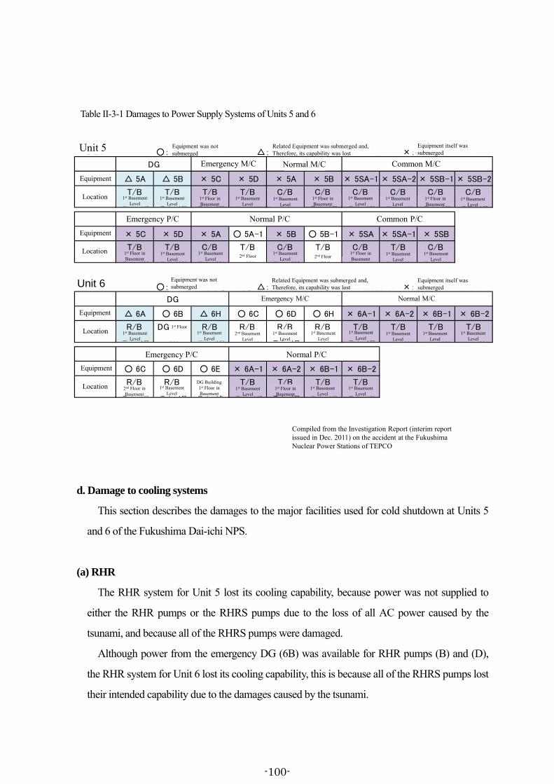
5号機 ○:機器は被水しなかった △:関連機器が被水したため機能喪失 ×:機器自体が被水した
機器 △ 5A △ 5B × 5C × 5D × 5A × 5B × 5SA-1 × 5SA-2 × 5SB-1 × 5SB-2
設置場所T/B
地下1階
T/B
地下1階
T/B
地下1階
T/B
地下1階
C/B
地下1階
C/B
地下1階
C/B
地下1階
C/B
地下1階
C/B
地下1階
C/B
地下1階
機器 × 5C × 5D × 5A ○ 5A-1 × 5B ○ 5B-1 × 5SA × 5SA-1 × 5SB
設置場所T/B
地下1階
T/B
地下1階
C/B
地下1階
T/B
2階
C/B
地下1階
T/B
2階
C/B
地下1階
T/B
地下1階
C/B
地下1階
6号機 ○:機器は被水しなかった △:関連機器が被水したため機能喪失 ×:機器自体が被水した
機器 △ 6A ○ 6B △ 6H ○ 6C ○ 6D ○ 6H × 6A-1 × 6A-2 × 6B-1 × 6B-2
設置場所R/B
地下1階
DG建屋
1階
R/B
地下1階
R/B
地下2階
R/B
地下1階
R/B
1階
T/B
地下1階
T/B
地下1階
T/B
地下1階
T/B
地下1階
機器 ○ 6C ○ 6D ○ 6E × 6A-1 × 6A-2 × 6B-1 × 6B-2
設置場所R/B
地下2階
R/B
地下1階
DG建屋
地下1階
T/B
地下1階
T/B
地下1階
T/B
地下1階
T/B
地下1階
非常用P/C 常用P/C
常用M/C非常用M/CDG
非常用P/C 常用P/C 共通P/C
非常用M/CDG 共通M/C常用M/C
Unit 6
Emergency M/C Common M/C
Unit 5
Normal P/C Common P/C
Emergency M/C
Emergency P/C Normal P/C
Normal M/C
Equipment was not submerged
Related Equipment was submerged and,Therefore, its capability was lost
Equipment itself wassubmerged
Equipment was notsubmerged
Related Equipment was submerged and,Therefore, its capability was lost
Compiled from the Investigation Report (interim report issued in Dec. 2011) on the accident at the Fukushima Nuclear Power Stations of TEPCO
Normal M/C
Equipment itself wassubmerged
Emergency P/C
2nd Floor inBasement
1st BasementLevel
DG Building1st Floor inBasement
1st BasementLevel
1st Floor inBasement
1st BasementLevel
1st BasementLevel
Equipment
Location
Equipment
Equipment
Equipment
Location
Location
Location
1st BasementLevel
1st Floor1st Basement
Level2nd Basement
Level1st Basement
Level1st Basement
Level1st Basement
Level1st Basement
Level1st Basement
Level1st Basement
Level
1st Floor inBasement
1st BasementLevel
1st BasementLevel
2nd Floor1st Basement
Level 2nd Floor1st Floor inBasement
1st BasementLevel
1st BasementLevel
1st BasementLevel
1st BasementLevel
1st Floor inBasement
1st BasementLevel
1st BasementLevel
1st Floor inBasement
1st BasementLevel
1st BasementLevel
1st Floor inBasement
1st BasementLevel
d. Damage to cooling systems
This section describes the damages to the major facilities used for cold shutdown at Units 5
and 6 of the Fukushima Dai-ichi NPS.
(a) RHR
The RHR system for Unit 5 lost its cooling capability, because power was not supplied to
either the RHR pumps or the RHRS pumps due to the loss of all AC power caused by the
tsunami, and because all of the RHRS pumps were damaged.
Although power from the emergency DG (6B) was available for RHR pumps (B) and (D),
the RHR system for Unit 6 lost its cooling capability, this is because all of the RHRS pumps lost
their intended capability due to the damages caused by the tsunami.
Table II-3-1 Damages to Power Supply Systems of Units 5 and 6
-100-

(b) MUWC
After the arrival of the tsunami, the MUWC system for Unit 5 lost its cooling capability,
because power was not supplied to the condensate transfer pump due to the loss of all AC
power.
However, the MUWC system for Unit 6 had retained its cooling capability, because power
was supplied to its condensate transfer pump from the emergency DG (6B) even after the
arrival of the tsunami.
(4) Situation from the moment of the earthquake until the arrival of the tsunami (between
14:46 and 15:35 on March 11)
a. Plant status at Units 5 and 6 at the Fukushima Dai-ichi NPS immediately before the
earthquake occurred
(a) Situation at Unit 5
Due to the routine inspections, the Unit 5 reactor had been shut down with fuels still inside
the reactor since January 3, 2011, and the reactor was in a state of cold shutdown.
On March 11, the day when the earthquake occurred, from around 8:30 the shift team
(meaning all members including the shift supervisor and the other shift operators; hereinafter
referred to “shift team”) had been filling the pressure vessel with water and had been increasing
its pressure180 in order to carry out a leak and hydrostatic test on the pressure vessel181.
At the moment of the earthquake the plant status of Unit 5 was: the reactor pressure was
approximately 7.15 MPa gage; the reactor water level was at about 8,700 mm on the shutdown
range water level indicator182 (hereinafter referred to as the “reactor water level indicator
(shutdown range);” see Attachment II-3-2); the reactor water temperature was approximately
90.6℃; and the SFP water temperature was approximately 23.7℃.
180 The leak and hydrostatic test on the pressure vessel refers to a test whereby the pressure vessel is filled with
water to confirm that there are no leaks with the valves, pipes, components, welded joints, and other parts in a pressurized state.
181 The Unit 5 pressure vessel head had been closed for the leak and hydrostatic test, while the containment vessel cover was left open. Furthermore, the main steam isolation valve (MSIV) outside the containment vessel had been left open at Unit 5.
182 The shutdown range water level indicator refers to a water level indicator that measures the reactor water level above TAF+4,170 mm. It has an indication range between 0 – 4,500 mm.
-101-

(b) Plant status at Unit 6
Due to the routine inspections, the Unit 6 reactor had been shut down with fuels still inside
the reactor since August 14, 2010, and the reactor was in a state of cold shutdown183.
At the moment of the earthquake, the plant status of Unit 6 was: the reactor pressure in Unit 6
was 0 MPa gage; the reactor water level was at about 1,400 mm on the upset range water level
indicator184 (hereinafter referred to as the “reactor water level indicator (upset range);” see
Attachment II-3-2); the reactor water temperature was approximately 26.0℃;and the SFP water
temperature was approximately 25.0℃.
b. Actions taken by the ERCs after the earthquake occurred
The actions taken by the Emergency Response Center at the TEPCO Head Office
(hereinafter referred to as “TEPCO ERC”) and the NPS ERC are described in Chapter IV 1 (1)
of the Interim Report.
c. Actions taken in the Units 5 & 6 main control room after the earthquake occurred
(i) After the earthquake occurred, the shift team at the Units 5 & 6 main control room
confirmed that it had lost offsite power supply, and also that emergency DGs for Unit 5 (5A and
5B) and those for Unit 6 (6A, 6B, and 6H) had all started via the displays on their control
panels185. The shift team also confirmed that no particular anomalies had arisen with major
parameters such as the reactor pressure and reactor water level through the displays on their
control panels, and also reported these pieces of information related to the plant to the NPS
ERC186.
183 The Unit 6 pressure vessel head and containment vessel cover were closed, but the pressure vessel vent pipe
valve had been left open. Furthermore, the MSIV outside the containment vessel had been left open at Unit 6. 184 The upset-range water level indicator refers to a water level indicator that measures the reactor water level above
TAF+4,196 mm. It has an indication range between 0 – 4,500 mm. Moreover, the upset water level indicator is installed only for Unit 6 of the Fukushima Dai-ichi NPS.
185 Just like the main control rooms for Units 1 & 2 and for Units 3 & 4, the Units 5 & 6 main control room is arranged with the shift supervisor’s seat in the center, and with the console panels and other equipment for Unit 5 on the left-hand side of the shift supervisor’s seat and those for Unit 6 on the right-hand side (see Attachments IV-3 and 7 of the Interim Report).
186 Upon receiving the message that a tsunami warning had been issued, the shift supervisor directed the workers in the building to return to the Units 5 & 6 main control room. In addition, he put top priority on their safety and so did not have them enter the buildings to check plant conditions.
-102-
(ii) Immediately after the arrival of the tsunami, the status indicator lamps showing operating
status of various components on the control panel went out one after another in the Units 5 & 6
main control room. In addition, since the status indicator lamps showing operating status of the
emergency DGs went out (except for one emergency DG at Unit (6B)), the shift team
confirmed that only one emergency DG at Unit 6 (6B) was in operation187.
On top of the fact that offsite power was lost at Unit 5, its emergency DGs (5A and 5B) had
also lost their capability to generate power. As a result, AC power (Trains A and B) was lost,
resulting in the station blackout (SBO). As a consequence, the lights on the Unit 5 side in the
Units 5 & 6 main control room went out, and only the emergency lights remained lit.
For Unit 5, the shift team in the Units 5 & 6 main control room lost the ability to check the
reading of monitoring instruments for Unit 5 such as the reactor water level indicator (wide
range and shutdown range), the reactor water temperature indicator, the S/C water level
indicator, the S/C water temperature indicator, and the SFP water temperature indicator, because
these indicators were run by AC power. On the other hand, the DC power (Trains A and B) at
Unit 5 started to be supplied from emergency batteries as a result of the loss of the AC power.
This switchover allowed the shift team to check the reading of monitoring instruments such as
the reactor pressure indicator (narrow range and wide range) and the reactor water level
indicator (narrow range), because these indicators were run by DC power.
For Unit 6, in addition to the fact that power was no longer being supplied from offsite power,
one emergency DG (6A) had lost its capability to generate power. Since AC power (Train A)
was no longer available, DC power (Train A) started to be supplied from the emergency
batteries. In contrast, another emergency DG (6B) had not been affected by the tsunami and had
continued to function, so AC power supply (Train B) was not interrupted188. Thanks to this
power supply, the lights on the Unit 6 side in the Units 5 & 6 main control room did not go out,
and so the shift team was able to check the reading of various monitoring instruments (part of
Train A and all of Train B) like the Unit 6 reactor water level indicator (upset range) and the
reactor pressure indicator.
187 At around midnight on March 12, three members of the shift team confirmed that the Unit 6 emergency DG (6B),
which was installed in the DG building, had started up. 188 The DC power to Unit 6 (Train B) was supplied from the Unit 6 emergency DG (6B) and was never switched
over to the power supply from the emergency batteries.
-103-

(5) Situation concerning reactor depressurization and water injection into the reactor
a. Action taken by the NPS ERC
Shortly after the arrival of tsunami, the NPS ERC was notified by the shift supervisor of Unit
5 and 6 that the Unit 5 emergency DGs (5A and 5B) stopped and that Unit 5 fell into SBO
conditions. In addition, they also reported that two emergency DGs for Unit 6 (6A and 6H) had
come to a halt and that only one emergency DG (6B) was operating. Upon having received this
report, the ERC concluded that in this situation the power supply for Units 5 and 6 would have
to be secured from the Unit 6 emergency DG (6B).
The ERC had grasped the information that heavy oil tanks had been washed up along the
seaside area at Units 1 through 4. Supposing that the seaside area at Units 5 and 6 was in similar
conditions, they thought that it would take time to restore the seawater system pumps. For this
reason, the ERC recognized that, during the period in which reactor cooling was interrupted at
Unit 5 & 6, it would have to depressurize reactors and inject water into them as needed.
In addition, since both Units 5 and 6 were undergoing routine inspections, it was hard to
conceive that there would be striking changes such as a sharp rise in reactor pressure or reactor
water level. Furthermore, the reactor water level at the moment of the earthquake was adequate.
Moreover, despite the fact that water must be injected into the reactors to make up for the
dropping reactor water levels due to the decay heat generated in the their fuels, the ERC
believed that there would be a relatively long deal of time to spare before the reactor state
reached such a stage.
b. Situation at Unit 5
(a) Details of the response plan for Unit 5
After the arrival of the tsunami, the emergency DGs at Unit 5 (5A and 5B) and two of the
emergency DGs at Unit 6 (6A and 6H) came to a halt. Given the situation, the shift supervisor
inferred that the emergency DG seawater (DGSW)189 pumps installed in the seaside area had
been submerged by the tsunami. What is more, the shift supervisor also thought that the other
seawater system pumps installed in the seaside area had also suffered similar damage.
In order to maintain stable cooling of the reactors, it was necessary to operate the RHR 189 A system that supplies seawater needed i to cool the emergency DGs.
-104-
systems. Adding to the fact that the Unit 5 RHR system had lost AC power for operating the
pumps, it was inferred that the RHRS pumps installed in the seaside area had suffered damage
from the tsunami. For these reasons, the shift supervisor concluded that it would take time to
restore the RHR systems.
At the moment of the earthquake, the reactor water level indicator (shutdown range) at Unit 5
showed that the reactor water level was at about 8,700 mm, suggesting that the reactor water
level had been kept at an adequate level and that, for the time being, the situation did not
necessitate the injection of water into the reactor. Nevertheless, since there were no clear
prospects that RHR system would restore its function, there was a possibility that reactor lost
every means of heat removal for an extended period of time. If such a situation occurred, it was
conceivable that the reactor water level would drop. For this reason, the shift supervisor thought
that it would be necessary to inject water into the reactor before it fell into such a state.
To start with, the Unit 5 pressure vessel was filled with water, and so it was not possible to
start the RCIC system and the HPCI system, both of which are steam-driven. Since all AC
power to Unit 5 had been lost, power supply had to be restored to run the systems related to the
alternative means for injecting water. Therefore, the shift supervisor examined various
alternative means of water injection and restoration of their power supply. The shift supervisor
took a number of factors into consideration for this, including: (1) the flow rate should be
remotely and easily controlled by operating the discharge valves on the RHR pipes from the
Units 5 & 6 main control room, (2) the amount of work required to restore the power supply to
the equipment needed should be relatively small, (3) the water should be supplied from the CST,
and the amount of stored water should be sufficient, and (4) a switchover to a different line
should make it possible to inject water not only into the reactor, but also into the SFP. In
consideration of these factors, the shift supervisor opted to inject water into the reactor from the
MUWC system via the RHR system190, and so he asked the ERC to restore the necessary power
190 The control rod drive mechanism was not used because power to the pump had been lost, and because methods
for cooling the pump had been lost due to the impact of the tsunami. On the other hand, the MUWC system had the air-cooling condensate transfer pump, so it did not require any cooling equipment.
There was another method of injecting water into the reactor from the fire protection system, which uses motor-driven fire pumps, but the shift team put priority on restoring the MUWC system, which they had operated frequently in plant operation. In actuality, the filtered water tank that was the water source for the fire protection system had leaks in its piping, and therefore was not available. What is more, the diesel-driven fire pump was
-105-

supply. However, at that point in time the ERC focused its response on Units 1 through 3, which
had been in operation at the moment of the earthquake, and thereby there were no prospects of
restoring the MUWC system for Unit 5 within a certain time frame.
On the other hand, at the moment of the earthquake, at Unit 5 the reactor pressure was as
high as approximately 7.15 MPa gage191, with a strong possibility that the pressure increased
thereafter. In order to inject water into the reactor from the MUWC system, the reactor pressure
had to be reduced to below the maximum discharge pressure for the condensate transfer pump,
which was 0.98 MPa gage. Therefore, for Unit 5, the shift supervisor concluded that it was
necessary to control the reactor pressure until it became possible to inject water into the reactor
from the MUWC system.
In general, in order to control the reactor pressure, the SR valves are remotely opened to
depressurize the reactor from the Units 5 & 6 main control room, letting the steam be
discharged from inside the pressure vessel into the S/C. However, before the earthquake, the
shift team had already taken measures to ensure that none of the SR valves be remotely
operated from the Units 5 & 6 main control room in order to conduct the leak and hydrostatic
test on the reactor pressure vessel at Unit 5. Specifically, to ensure that the SR valves were not
opened due to operational error, the electrical power fuse had been removed from the electronic
circuits on the back of the control panel in the Units 5 & 6 main control room. In addition, the
nitrogen supply line valve had been closed and, in parallel, the accumulator blow valve had
been closed, so that nitrogen would not be supplied to the SR valves, which were
nitrogen-driven valves.
Accordingly, in order to remotely open the SR valves from the Units 5 & 6 main control
room, the shift operators had to connect the electrical power fuse terminals to the electronic
circuits on the back of the control panel in the main control room. In addition, the shift operators
under maintenance work and was not available either.
According to the operating procedures, provided that the RCIC, HPCI and low-pressure water injection systems were not available, priority should be given to the MUWC system as an alternative means to inject water into the reactor.
191 The reactor pressure at the Unit 5 had been raised to approximately 7.15 MPa gage to conduct the leak and hydrostatic test on the pressure vessel. Since the pump for the control rod drive mechanism that had been operated to increase the reactor pressure stopped in the wake of the earthquake, the reactor pressure dropped to roughly 5.0 MPa gage and began rising again due to the decay heat.
-106-
also had to operate the manual valves installed inside the containment vessel in order to
configure the line for supplying nitrogen to the SR valves.
However, the shift supervisor wanted to avoid field work in the containment vessel—which
had poor footing without light—as much as possible. He thought that he had to first secure
another means of reducing the reactor pressure without using the SR valves to control the
reactor pressure and decided to carry out work procedures designed to configure the line for
injecting water into the reactor from the MUWC system.
(b) Reactor depressurization through the vessel head vent nozzle
Beginning in the evening of March 11, the NRC ERC Operation Team and the shift team
examined the means by which the reactor could be depressurized without actually entering the
containment vessel in Unit 5192. Then the ERC and the shift team figured out that the reactor
would be depressurized if water could be discharged from the reactor pressure vessel, which
was full of water, by opening the vessel head vent nozzle. They decided to act on this idea and,
from early in the morning of March12, started to examine how to put this idea into practice.
In order to open the vessel head vent nozzle, nitrogen had to be supplied to the vent nozzle,
which was driven by nitrogen, from the nitrogen tank installed outdoors. However, an
electromagnetic valve sitting on the nitrogen supply line was an obstacle to the nitrogen supply,
because it was impossible to excite the electromagnetic valve due to the loss of power supply.
As such, from about 5:00 on March 12 the ERC Operation Team inserted a tool into this
electromagnetic valve to force it open on the first floor inside the Unit 5 R/B and successfully
configured the nitrogen supply line. After this, at about 6:06 that same day the shift team
remotely opened the vessel head vent nozzle from the control panel in the Units 5 & 6 main
control room193.
After the above-mentioned operation completed, the reactor pressure was reduced from
approximately 8.3 MPa gage at around 06:00 that day194 to about 0.2 MPa gage by around
192 Soon after 21:00 on March 11, the shift team attempted to reduce the reactor pressure by discharging water from
the Unit 5 pressure vessel, which was full of water, by using the HPCI and RCIC steam pipes. However, this attempt had almost no observable effects on reducing the pressure.
193 At that time, the vessel head vent nozzle was being supplied with power from Unit 5 250V DC emergency batteries through the vital 120/240V AC distribution panel.
194 From around 1:40 on March 12, the SR valves automatically opened due to safety valve function, and so the
-107-
06:30 that day. And then, in order to keep the reactor pressure low, the shift team kept the vessel
head vent nozzle open thereafter.
(c) Preparations for injecting water into the reactor
Since the reactor had been depressurized by opening the vessel head vent nozzle, the shift
team confirmed that it secured a means of depressurizing the reactor and decided to configure
the line for injecting water into the reactor from the MUWC system via the RHR system.
In order to inject water into the reactor from the MUWC system via the RHR system, the
shift team had to configure the water injection line. The shift team decided that, before starting
to configure the water injection line, it should interconnect power from the Unit 6 emergency
DG (6B) to Unit 5 by using the existing lines which had been installed as a provision for
accident management measures (hereinafter referred to as the “AM bus tie-line”). The AM bus
tie-line is a line connecting the Unit 5 RHRMCC with the Unit 6 T/BMCC6C-2, so that power
could be interconnected between Units 5 and 6 by closing a circuit breaker. Thanks to the
interconnection, it became possible to restore the power supply to the motor-operated valves
sitting on the reactor water injection line from the MUWC system.
And, on the first floor of the Unit 6 T/B and the first floor of the Unit 5 R/B, shift operators
closed circuit breakers built into the AM bus tie-line by around 08:13 on March 12. Then,
power was then supplied from the Unit 6 T/BMCC6C-2, which was supplied with power from
a Unit 6 P/C6C195, to the Unit 5 RHRMCC, thereby supplying power from Unit 6 to Unit 5 (see
Attachment II-3-3)196. As a result, this made it possible for the shift team to control the
MUWC-RHR interconnecting pipe valves and the RHR discharge valves, both of which are
motor-operated valves, from the Units 5 & 6 main control room.
On the other hand, as described in (a), power supply had to be secured for the condensate
reactor pressure at the Unit 5 was maintained at around 8.1MPa gage – 8.3 MPa gage.
195 As is described later in c. (b), at around 6:03 on March 12 power was supplied to the Unit 6 P/C6C from the Unit 6 emergency DG (6B) via the bus tie-line installed between Unit 6 P/C6C and the Unit 6 P/C6D.
196 The Unit 5 125V DC emergency batteries were depleted around 1:00 on March 12. Up until about 8:13 of the same day power was supplied from the Unit 6 emergency DG (6B) to the Unit 5 RHRMCC, thereby ensuring power to the Unit 5 reactor pressure indicator (narrow range) and the reactor water level indicator (narrow range), both of which were supplied with power from the Unit 5 125V DC emergency batteries. As the Unit 5 125V DC emergency batteries were depleted, the shift team confirmed the reactor pressure from the reading of the reactor pressure indicator that is operated by a different power supply.
-108-
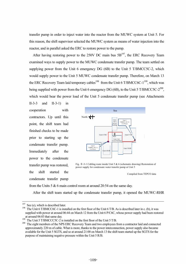
transfer pump in order to inject water into the reactor from the MUWC system at Unit 5. For
this reason, the shift supervisor selected the MUWC system as means of water injection into the
reactor, and in parallel asked the ERC to restore power to the pump.
After having restoring power to the 250V DC main bus 5B197, the ERC Recovery Team
examined ways to supply power to the MUWC condensate transfer pump. The team settled on
supplying power from the Unit 6 emergency DG (6B) to the Unit 5 T/BMCC5C-2, which
would supply power to the Unit 5 MUWC condensate transfer pump. Therefore, on March 13
the ERC Recovery Team laid temporary cables198 from the Unit 6 T/BMCC6C-1199, which was
being supplied with power from the Unit 6 emergency DG (6B), to the Unit 5 T/BMCC5C-2200,
which would bear the power load of the Unit 5 condensate transfer pump (see Attachments
II-3-3 and II-3-1) in
cooperation with
contractors. Up until this
point, the shift team had
finished checks to be made
prior to starting up the
condensate transfer pump.
Immediately after the
power to the condensate
transfer pump was restored,
the shift started the
condensate transfer pump
from the Units 5 & 6 main control room at around 20:54 on the same day.
After the shift team started up the condensate transfer pump, it opened the MUWC-RHR
197 See (e), which is described later. 198 The Unit 6 T/BMCC6C-1 is installed on the first floor of the Unit 6 T/B. As is described later in c. (b), it was
supplied with power at around 06:44 on March 12 from the Unit 6 P/C6C, whose power supply had been restored at around 06:03 that same day.
199 The Unit 5 T/BMCCC5C-2 is installed on the first floor of the Unit 5 T/B. 200 The eight members of the NPS ERC Recovery Team and two employees from a contractor laid and connected
approximately 220 m of cable. What is more, thanks to the power interconnection, power supply also became available for the Unit 5 SGTS, and so at around 21:00 on March 13 the shift team started up the SGTS for the purpose of maintaining negative pressure within the Unit 5 R/B.
東京電力作成資料を基に作成
North
Unit 6T/BMCC (6C-1)
(1st Floor)
Unit 5T/BMCC (2C-2)
(1st Floor)
Unit 6 T/B Unit 5 T/B
Unit 6 R/B
Unit 5 R/B
Sea
Units 5 & 6Control Building
Stairs
Compiled from TEPCO data
Fig. Ⅱ-3-1 Cabling route inside Unit 5 & 6 (schematic drawing) Restoration of power supply for condensate water transfer pump at Unit 5
Units5 & 6
ServiceBuilding
-109-

interconnecting pipe valves and RHR discharge valves at around 21:00 that same day and
configured the line for injecting water into the reactor from the MUWC system via the Train B
of the RHR system (see Attachment II-3-4). However, as is described later in (d), despite the
fact that up until then the vessel head vent nozzle had been kept open, the reactor pressure had
been rising gradually over about 1.5 MPa gage. As such, without depressurizing the reactor, the
shift team would not be able to inject water into the reactor from the MUWC system.
(d) Depressurizing the reactor by opening SR valves and injecting water into the reactor
As was described in (b), after the shift team opened the vessel head vent nozzle to
depressurize the reactor at around 06:06 on March 12, it kept the vent valve open and
continuously monitored indicators like the reactor pressure indicator.
Although the vessel head vent nozzle had been kept open, the reactor pressure began to rise
gradually201. The shift team attempted to depressurize the reactor by discharging water from the
pressure vessel through the RHR piping and the main steam pipes from March 13. But the shift
team was unable to lower the reactor pressure by either of these means. As such, the shift team
thought that it had no other option other than to carry out work inside the containment vessel.
As was described in (a), in order to operate the SR valves for Unit 5 from the Units 5 & 6
main control room, the shift team had to connect the terminal for the electrical fuse to the
electrical circuit on the back of the control panel inside this main control room and had to enter
the containment vessel to configure the nitrogen supply line.
Moreover, the shift team had locked with tools the SR valves whose set pressure were low
for functioning as safety valves, excluding three valves (Valves A, G, and H)202 whose set
pressure were high for functioning as safety valves, in a position to ensure that those valves
would not automatically open due to safety valve function while the pressure was kept high for
conducting the leak and hydrostatic test on the reactor pressure vessel. Because of this, the shift
team decided to use one of the three valves (Valves A, G, and H), none of which required the
201 After the vessel head vent nozzle had been opened, the indication of reactor pressure was about 0.2 MPa gage at
around 06:30 on March 12. The reactor pressure continued to climb gradually and exceeded about 1.0 MPa gage at around 10:00 on March 13. The cross section of the vessel head vent nozzle is one-ninth of that of the SR valve.
202 The set pressure for the SR valves to function as safety valves is 8.55 MPa gage for Valves A, G, and H, respectively.
-110-

task of removing the tools from the valves, and concluded to use Valve A for depressurizing the
reactor on the grounds that this valve required the least amount of work to configure its nitrogen
supply line.
From around 02:25 on the same day the shift team had started to configure the nitrogen
supply line to this SR valve (Valve A) and, at around 05:00 on the same day, remotely opened
this SR valve (Valve A) from the Units 5 & 6 main control room203. As a result, the Unit 5
reactor pressure, which had been approximately 2.0 MPa gage at around 05:00 that day, fell
down to about 0.8 MPa gage at around 05:20.
Afterwards, since the reactor water level dropped as a result of reactor depressurization by
opening this SR valve, the shift team remotely opened the RHR system discharge valve from
the Units 5 & 6 main control room at around 05:30 on the same day and injected water into the
reactor from the MUWC system via the RHR Train B204.
From then onwards, the shift team monitored the reactor pressure indicator and the reactor
water level indicator and maintained the reactor pressure and water level by setting 2 MPa gage
as the reference criteria for opening the SR valve. That is to say, whenever the reactor pressure
exceeded the reference criteria, the shift team depressurized the reactor to the pressure lower
than about 0.8 MPa gage by operating the SR valve and injected water from the MUWC
system.
(e) Restoration of power to the monitoring instruments and other equipment
As was described in (4) c., since Unit 5 lost AC power after the arrival of tsunami, the shift
team lost the ability to check the reading of monitoring instruments that were operated by AC
power, such as the reactor water level indicator (shutdown range)205. For this reason,
203 The power to the SR valve (Valve A) was supplied from 125V DC emergency batteries via the Unit 5 125V DC
main bus 5A and the Unit 5 125V DC distribution panel 5A-1. After the Unit 5 125V DC emergency batteries were depleted at around 01:00 on March 12, power could be supplied to the SR valve (Valve A) from the Unit 5 RHRMCC to which power had been restored from 08:13 the same day.
204 The reactor water level indicator (shutdown range) showed that the reactor water level was about 2,200 mm at around 05:00 on March 14 prior to the opening of the SR valve. At around 05:30 this same day after the SR valve had been opened, the indication of the reactor water level was approximately 950 mm, before rising to 2,000 mm at around 06:10 that day after the water injection via the MUWC system.
205 The shift team confirmed the reactor pressure by using the reactor pressure indicator (wide range) that is powered by the Unit 5 250V DC emergency batteries and the 125V DC emergency batteries. The shift team also confirmed that the reactor water level was above 1,500 mm by converting the indication given by the reactor
-111-

immediately after they lost the ability to check the reading of monitoring instruments, the shift
supervisor asked the ERC to restore the capability of the monitoring instruments.
Upon receiving this request, the ERC Recovery Team decided to interconnect the power
from the Unit 6 emergency DG (6B), which was still operating even after the tsunami, to the
main circuit power switchboard for the AC 120/240V instrumentation (hereinafter referred to as
the “instrumentation switchboard”) for Unit 5. This was because these monitoring instruments
had been supplied with power from this instrumentation switchboard via a 120V AC
instrumentation distribution panel. Therefore, the ERC Recovery Team examined which route
was the best for laying temporary cables, and decided to lay the said cables from the Unit 6
instrumentation
switchboard, which had
been receiving power from
the Unit 6 emergency DG
(6B), to the Unit 5
instrumentation
switchboard206.
The NPS ERC Recovery
Team started work to lay
these temporary cables at
around 03:00 on March 12
and finished the cable
laying work by about 05:00
that same day (see
Attachment II-3-3 and
Figure II-3-2) 207 . As a
water level indicator (narrow range), which is powered by DC batteries, to the value corresponding to the indication on the reactor water level indicator (shutdown range).
206 The Unit 6 instrumentation switchboard is installed on the basement floor of the Unit 5 T/B, while the Unit 5 instrumentation switchboard is installed on the first floor of the Units 5&6 C/B, respectively.
207 Since Units 5 and 6 were undergoing routine inspections, a number of cables were stored in the warehouse of contractors and were used for this task. Regarding the task of interconnecting the power, four members of the ERC Recovery Team laid and connected about 70 m length of cables.
東京電力作成資料を基に作成
Compiled from TEPCO data
Unit 6T/BMCC (6C-1)
(1st floor)
Unit 5Instrumentation
switch board(1st floor)
NorthUnit 6
Instrumentation switch board
(mezzanine levelbelow ground)
Unit 5T/BMCC (5D-1)(mezzanine levelbelow ground)
Unit 6 T/B
Unit 6 R/B
Unit 5 R/B
Unit 5 T/B
Units 5 & 6Control Building
Sea
Stairs
Units5 & 6
ServiceBuilding
Fig. II-3-2 Units 5 & 6 Cabling route (schematic drawing)
Restoration of power supply for AC monitoring instruments and process computer at Unit 5
-112-
result, the shift team was able to confirm the reading of the indicators powered by the Unit 5 AC
power, such as the reactor water level indicator (shutdown range), from the Units 5 & 6 main
control room208.
However, the Unit 5 250V DC emergency batteries were depleted at around 16:52 on the
same day. As a result, various monitoring instruments for Unit 5 and the equipment that
displays the operating conditions of the various facilities for Unit 5 (hereinafter referred to as
the “process computer system”) stopped functioning209. Hence, the shift team requested that the
ERC restore the power for these instruments and equipment. Upon receiving this request, the
ERC Recovery Team examined different ways to supply power from the Unit 6 emergency DG
(6B) to the Unit 5 250V DC main bus 5B, which bore the power load for the Unit 5 process
computer system. As such, the Recovery Team decided to lay temporary cables from the Unit 6
T/BMCC6C-1, which had been receiving power from the Unit 6 emergency DG (6B), to the
load side of the Unit 5 T/BMCC5D-1, which bore the power load for the Unit 5 250V DC main
bus 5B210. From around midnight on March 13, the ERC Recovery Team started work in
cooperation with contractors and completed work by about 5:37 that same day (see Attachment
II-3-3 and Figure II-3-2)211. As a result, the shift team was able to check the reading of the
various monitoring instruments on the control panel in the Units 5 & 6 main control room212.
c. Situation at Unit 6
(a) Details of the examination concerning the response plan for Unit 6
At the moment of the earthquake, the reactor water level indicator (upset range) showed that
208 Some of these monitoring instruments require 120V AC power, some other require 24V DC power, and the
others require both of them for their power supply. The 24V DC power is supplied, by lowering the voltage and converting AC to DC, from a distribution panel for the 120V AC instruments.
209 Since the arrival of the tsunami, the power supply to the Unit 5 process computer system was switched over to the power supply from the Unit 5 250V DC emergency batteries via the 250V DC main bus 5B and the process computer system power distribution panel.
210 The Unit 6 T/BMCC6C-1 is located on the first floor of the Unit 6 T/B. Furthermore, as is explained in c. (b) later, this MCC was supplied with power at around 6:44 on March 12 from the Unit 6 P/C6C, to which power had been restored at around 06:03 that same day. What is more, the Unit 5 T/BMCC5D-1 is installed in the basement floor of the Unit 5 T/B.
211 Six members of the ERC Recovery Team and two employees from the contractor laid and connected about 70 m length of cables.
212 Some of Unit 5 reactor pressure indicators (wide range and narrow range) and reactor water level indicators (narrow range) were supplied with power from the Unit 5 250V DC emergency batteries. By the power interconnection, power supply was restored for these monitoring instruments.
-113-

reactor water level for Unit 6 was at approximately 1,400 mm, which was regarded as adequate.
In addition, the reactor pressure was kept sufficiently low at just about atmospheric pressure.
Since both the reactor water level and the reactor pressure were stable, the shift supervisor
thought that the plant state would not require the injection of water into the reactor for the time
being at Unit 6.
However, just like with the Unit 5 RHR system, it was anticipated that the time needed to
restore the Unit 6 RHR system would be long. If reactor cooling was suspended for a long
period of time, the reactor water level was likely to fall before long. Therefore the shift
supervisor decided that water should be injected into the Unit 6 reactor, if need be, from the
MUWC system until the RHR was restored, just like with Unit 5213.
(b) Details of the injection of water into the Unit 6 reactor
At Unit 6, the MUWC-RHR interconnecting pipe valve had to be operated in order to
configure the line for injecting water into the reactor from the MUWC system via the RHR
system. In addition, the MUWC-RHR interconnecting pipe valve was located on the RHR
Train A and was not supplied with power, after the Unit 6 emergency DG (6A) had stopped.
Because of this, the shift team decided that they would connect Unit 6 P/C6C and P/C6D to
interconnect power from the Unit 6 emergency DG (6B) to the Unit 6 MUWC-RHR
interconnecting pipe valve and the discharge valve of the RHR system piping214.
At around 06:03 on March 12 the shift team closed the circuit breaker built into the bus
tie-line between Unit 6 P/C6C and P/C6D (see Attachment II-3-3). As a result, power was
supplied to Unit 6 P/Cs (6C) and the load connected to this P/C. This allowed the shift team to
configure the line for injecting water into the reactor from the MUWC system via the Train A of
213 Power to the Unit 6 MUWC condensate transfer pump was secured by the Unit 6 emergency DG (6B). 214 At Unit 6, motor-operated valves for the MUWC-RHR interconnecting pipe valves are installed on the Train A
of the Unit 6 RHR, and are supplied with power from the Unit 6 P/C6C via a Unit 6 R/BMCC6C-7. Moreover, the Unit 6 RHR Train A discharge valve is also powered by the Unit 6 P/C6C via a Unit 6 R/BMCC6C-6.
Also, regarding the power supply facilities which, as mentioned in Chapter II 3 (3) b of the Interim Report, had no clear evidence of having maintained its capability, the Unit 6 P/C6C is now believed to have kept its capability, because it did not require any special restoration work to receive power from the Unit 6 emergency DG (6B) via the Unit 6 P/C6D at around 06:03 on March 12. In addition, the Unit 6 P/C6D and P/C/6E also maintained their capabilities, because they received power from the Unit 6 emergency DG (6B).
-114-

RHR system from the Units 5 & 6 main control room (see Attachment II-3-5)215.
Afterwards, the shift team continued to monitor the reactor water level. From about 21:30 on
March 14 onwards, the shift team intermittently injected water into the reactor from the MUWC
system to make up for the water evaporated due to the decay heat, thus maintaining the reactor
water level between about 1,300 mm to about 3,000 mm on the reactor water level indicator
(upset range)216.
(6) Status of the SFP up until the restoration of the RHR system and the response to this
a. Replenishing the SFP with water
The seawater system pumps for Units 5 and 6 were submerged by the tsunami and it
rendered the RHR system and the fuel pool cooling and cleanup (FPC) systems217 inoperable,
resulting in a situation in which not only the reactors but also the SFPs could not be cooled. For
this reason, after the arrival of the tsunami the shift supervisor predicted that the water
temperature in the SFP would start to rise.
Although about two days had elapsed since the arrival of the tsunami, the water temperatures
for the SFPs in Units 5 and 6 were almost identical to the values indicated prior to the
earthquake or lower than these values218. Because of this, the shift supervisor was concerned
that water had spilled out of the SFPs shaken by the earthquake, letting the water levels drop
below the range of the SFP water temperature gages219 and that the gages did not measure the
215 At about 13:20 on March 13 the shift team started up the Unit 6 condensate transfer pump. Following the startup
it configured the line for injecting water into the reactor from the MUWC system via the RHR system and confirmed that it was possible to inject water into the reactor.
216 The reactor water level, which had been approximately 1,800 mm on the reactor water level indicator (upset range) at around 21:30 on March 14, was approximately 3,000 mm at about 21:55 on the same day following the completion of the water injection from the MUWC system. The shift team decided to maintain the reactor water level as high as possible to the extent that would not submerge the main steam pipe and also decided to inject water from the MUWC system up to the level close to the bottom edge of the main steam pipe nozzle.
217 The FPC is a cleaning system that maintains the SFP water quality at the pre-determined levels by removing impurities while cooling the SFP water. Since the seawater system pumps, which supply seawater to the Unit 5 and 6 FPC heat exchangers, suffered damage from the tsunami, the FPC lost its heat removal capability. What is more, the Unit 5 FPC pump lost power following the loss of offsite power after the earthquake, so it was not impossible to start it up.
218 As of about 12:00 on March 13, the Unit 5 SFP water temperature indicator was showing that the temperature was approximately 26℃, while the Unit 6 SFP water temperature indicator was showing that the temperature was approximately 18℃.
219 The water temperature gages for the Units 5 and 6 SFPs are located about 11.2 m above the SFP floors. In addition, the Units 5 and 6 SFPs store nuclear fuels up to a height of about 4 m from the SFP floor, and the SFP
-115-
SFP water temperature but the air temperature above the water surface. Therefore, the shift team
and ERC decided to replenish the SFPs with water after finishing the water injection into the
Unit 5 reactor.
To begin with, in order to configure the line for injecting water into the Unit 5 SFP from the
MUWC system via the RHR and FPC systems, the shift team opened the manual valves on the
fourth floor of the Unit 5 R/B and remotely operated the motor-operated valves from the Units 5
& 6 main control room in the morning of March 14. They then began replenishing the Unit 5
SFP with water from the MUWC system at around 09:27 on the same day (see Attachment
II-3-4). As a result, the Unit 5 SFP water temperature indicator that had read approximately
32.5℃ at around 9:27 that day before the SFP was replenished gave a reading of about 48℃ at
about 09:58 that day. On this account, the shift team determined that the SFP water level had
been restored high enough to let the SFP water temperature gage stay in contact with the water,
thereby allowing them to accurately measure the SFP water temperature. So the team stopped
replenishing the SFP at about 09:58 that same day.
Subsequent to the replenishment of the Unit 5 SFP, at Unit 6 the shift team opened the
manual valves on the fifth floor of the Unit 6 R/B and remotely operated the motor-operated
valves from the Units 5 & 6 main control room in order to configure the line for injecting water
into the Unit 6 SFP from the MUWC system via the RHR and FPC systems. They then began
replenishing the Unit 6 SFP from the MUWC system at around 14:13 on the same day (see
Attachment II-3-5)220. As a result, the Unit 6 SFP water temperature indicator that had read
approximately 21.5℃ at around 14:13 that day before replenishing the SFP gave a reading of
about 50.5℃ as of about 15:03 that day. It indicated that the water level in the skimmer surge
tank had been increased to an adequate level. On this account, the shift team determined that
just like the Unit 5 SFP, this had allowed them to accurately measure the SFP water temperature
for Unit 6. So the team stopped replenishing the SFP with water at about 15:03 that same day.
water level is maintained at the height of 11.5 m above the SFP floor.
220 Prior to replenishing the Unit 6 SFP with water, the shift team visually inspected the SFP from the sixth floor of the R/B and confirmed that SFP water level had fallen. In addition, the shift team then moved to the fifth floor of the Unit 5 R/B to make visual inspection of the Unit 5 SFP confirmed that the pool was not full of water. Therefore, the team replenished the Unit 5 SFP once again from about 14:35 until 15:08 on March 14 in parallel with the replenishment the Unit 6 SFP.
-116-
b. Measures to control to water temperature rise in the SFPs
As was described in paragraph a., due to the fact that the SFPs were replenished with water
from the MUWC systems and that the SFP water level was restored, the ERC supposed that the
fuels in the SFPs had been covered with water. However, in the situation that the SFP cooling
had yet to be recovered, the ERC was concerned that if the water temperatures in the SFPs
continued to rise, the rising humidity inside the buildings would act as a factor that could cause
component failures and have a negative impact on the atmosphere in the buildings.
Therefore, the ERC and the shift team decided that they should implement measures to
control the rise of water temperatures in the SFPs.
(a) Response for Unit 5
Since the Unit 5 FPC pump had lost power supply, it was impossible to control the rise of
water temperature in the SFP by circulating SFP water through the FPC. For this reason, in
order to control the rise of water temperature in the Unit 5 SFP, the ERC decided to discharge
SFP water into the S/C via the RHR system and, in parallel, replace the SFP water with the
water pumped into the SFP from the MUWC system via the RHR and FPC systems. The ERC
instructed the shift team to act upon the decision at around 21:00 on March 16. The shift
supervisor was concerned about the possibility that the S/C water level and S/C water
temperature would rise as a result of discharging the SFP water into the S/C, thereby
compromising the S/C's pressure suppression capability. And then, through consultations with
the ERC, the shift supervisor concluded that the S/C still had some spare capacity and decided
to go ahead with replacing the SFP water.
Upon receiving this decision, the shift team began configuring both the line for discharging
the SFP water into the S/C and the line for replenishing the SFP from the MUWC system from
around 21:00 that same day. They then started replacing the SFP water from around 22:16 that
day (see Attachment II-3-4). Later also, the shift team continued replacing the SFP water while
monitoring the S/C water level and other parameters, until this replacement was terminated at
around 05:43 on March 17. Between before and after the replacement of SFP water, the water
temperature in the Unit 5 SFP rose only about 0.2℃, staying at almost the same. For this reason
the ERC and the shift team determined that the rise in the SFP water temperature had been kept
-117-
in check to a certain extent.
(b) Response for Unit 6
With respect to the Unit 6 FPC, although the seawater system pumps had lost their heat
removal function due to the damage caused by the tsunami, it was possible to operate the FPC
pump itself relying on power supplied from the Unit 6 emergency DG (6B). Because of this, the
ERC decided to control the rise in the SFP water temperature by circulating the water in the
SFP by operating the FPC without heat removal function and instructed the shift team to act on
the decision during the morning of March 16.
Upon receiving these instructions, the shift team circulated the SFP water by operating the
FPC from around 13:10 until 21:44 on March 16 (see Attachment II-3-5)221. This did not result
in any rise in the SFP water temperature between before and after the circulation of the SFP
water, and so the ERC and the shift team determined that the rise in the SFP water temperature
had been kept in check to a certain extent222.
(7) Situation from the restoration of the RHR system until the cold shutdown
a. Structure for examining the restoration of the RHR system
The TEPCO ERC recognized that, comparing Units 5 & 6 with Units 1 through 3, there was
less urgency when it came to getting the Units 5 and 6 reactors under control, because the
amount of decay heat generated in the fuels was relatively little and because the reactor water
levels in those reactors had been maintained. However, the TEPCO ERC grasped the situation
that the SFP water temperatures and reactor water temperatures for Units 5 and 6 were on the
rise. In the evening of March 15, the TEPCO ERC instructed the Nuclear Power Engineering &
Recovery Team of the TEPCO ERC (hereinafter referred to as “the Nuclear Team”) to work out
a medium to long-term plan for cooling the reactors and SFPs at Units 5 and 6. In addition, the
TEPCO ERC also instructed the Thermal Power Recovery Team of the TEPCO ERC to take
221 The shift team thought that, if the FPC pump continued to be operated over an extended period of time then the
heat generated by this pump would be transferred to the SFP water, because there were no means for cooling the FPC. Because of this, after confirming that this had functioned to some extent to control the rise in the SFP water temperature, the shift team stopped the FPC pump.
222 After this, the shift team circulated the water in the Unit 6 SFP, as needed, in the period up until the RHR system was restored.
-118-
part in this task.
Upon receiving their instructions, the Nuclear Team and the Thermal Power Recovery Team
(hereinafter referred to as the “TEPCO RHR System Recovery Team”) began examining
methods to cool the reactors and SFPs for Units 5 and 6 in cooperation with the contractors
starting from the morning of March 16223. The contractors offered a proposal to the TEPCO
RHR System Recovery Team that submersible pumps (hereinafter referred to as “temporary
submersible pumps”) be installed in place of the RHRS pumps that suffered damage by the
tsunami, in order to use the RHR system to cool the reactors and SFPs. It was decided that
TEPCO take the initiative in devising a specific plan to restore the RHR system and that the
contractors take the lead in working out a specific plan to restore the RHR cooling capability224.
b. Confirmation of the status of the equipment to be restored and the status of examinations
for the restoration plans
With regard to the Unit 5 RHR system, the TEPCO RHR System Recovery Team decided to
supply power from the Unit 6 emergency DG (6B) to the Unit 5 RHR pumps by laying
temporary cables, because Unit 5 had been hit by the station blackout (SBO). In addition, the
TEPCO RHR System Recovery Team opted to restore the pump of Train A of the Unit 5 RHR
system taking into consideration the conditions of the M/C for attaching temporary cables225.
The team formulated a plan to connect a bus tie-line between the Unit 6 M/C6C and M/C6D226
and lay temporary cables from the Unit 6 M/C6C to the Unit 5 RHR system pump. The team
223 Up until this point the TEPCO ERC Nuclear Team had been examining proposals to restore the FPCs and
reactor coolant cleanup systems for Units 5 and 6 in order to carry out medium to long-term cooling of the reactors, but it was unable to reach a decision on how to go about restoring the seawater system pumps.
On the other hand, as is described in b. later on, starting on March 11 the said contractor had begun to internally procure pumps, cables, and other equipment to be used as replacements for the equipment that had been rendered inoperable inside the Fukushima Dai-ichi NPS, based upon the information provided by the TEPCO ERC. What is more, the contractor began explaining about the equipment to be used including the temporary submersible pumps to the TEPCO ERC Nuclear Team from March 15 onwards, while also instructing its employees staying at the Fukushima Dai-ichi NPS to carry out onsite surveys.
224 For the RHR system, since the required work consisted primarily of restoring the existing facilities themselves, TEPCO took charge of this work. On the other hand, for the RHRS system work mainly consisted of installing temporary submersible pumps, so the contractor took charge of this work.
225 The structure of the Unit 5 M/C5C is divided into two layers, an upper layer and a lower layer, and there was a strong possibility that, at the very least, the temporary cable connections installed in the upper layer were available. On the other hand, another Unit 5 M/C5D has an integrated structure down to the floor, with a strong possibility that the cable connections for the RHR pumps had been submerged.
226 The Unit 6 M/C6D did not have a spare circuit breaker for connecting the temporary cables.
-119-
presented the plan to the ERC at around 18:30 on March 16.
Upon receiving this plan, the NPS ERC opted for an alternative plan to supply power to the
Unit 5 RHR pumps from other than the Unit 6 emergency DG (6B) in order to avoid troubles
with the work of connecting the bus tie-line between the Unit 6 M/C6C and M/C6D as much as
possible227. The ERC obtained the approval of the alternative plan from the TEPCO RHR
System Recovery Team that same night. From March 17, the ERC began measuring the
insulation resistance of the power supply panels for the Unit 5 RHR pumps and the power
supply panels for Units 5 and 6, and then selected equipment that could be used to restore the
Unit 5 RHR system228. Moreover, from March 17 until about 14:00 on March 18, the ERC
confirmed that the Unit 6 emergency DG (6A) and its auxiliary systems, including the DGSW
pump motor for this emergency DG (6A), were available229.
Base on the above-mentioned confirmations, shortly after 14:00 on March 18, the ERC
settled on a plan to restore the Unit 5 RHR pump (C) by interconnecting power to this pump
from the Unit 6 emergency DG (6A).
On the other hand, for the Unit 6 RHR system the TEPCO RHR System Recovery Team
decided to use the Unit 6 RHR pump by connecting this pump to the Unit 6 M/C6D that was
supplied with power from the Unit 6 emergency DG (6B).
At the same time, at around midnight on March 16 the TEPCO RHR System Recovery Team
submitted to the ERC the plan that had been formulated under the leadership of the contractors
to restore the RHR cooling function by using equipment like temporary submersible pumps,
truck-mounted generators, and temporary cables.
Regarding the materials needed for the installation of the temporary submersible pumps and
227 The NPS ERC was concerned that if something went wrong during the work to connect the Unit 6 M/C6C and
M/C6D with the bus tie-line, then this could lead to trip of the Unit 6 emergency DG (6B). 228 For the pumps of the Train A of the Unit 5 RHR system (A and C), the NPS ERC Recovery Team found that
only the Unit 5 RHR pumps (C) was available when the team measured the insulation resistance at around 11:00 on March 17.
229 From March 15 onward, the shift team confirmed the status of the Unit 6 emergency DG (6A) and its auxiliary systems as part of its efforts to restore this emergency DG as a backup to the other Unit 6 emergency DG (6B). By early dawn on March 17, the shift team reported to the NPS ERC that there were no apparent problems with it.
At the same time, the NPS ERC Recovery Team had been performing inspections on the various equipment since March 15. The team performed a visual inspection on the DGSW pump on March 16, and also rotated the pump rotating shaft to show the shaft was not stuck.
Therefore, the NPS ERC examined the ways to restore the RHR system based upon these confirmation results.
-120-

other equipment, the contractors had obtained from the TEPCO ERC the information on the
extent of the damage at the Fukushima Dai-ichi NPS, including the fact that the seawater
system pumps and power supply panels had suffered flood damage. Because of this, on March
11, the contractors had begun examining whether it would be possible to procure a pump with
as large a capacity as possible among them, despite the fact that its specific purpose had not
been specified230. After this, on March 16 it was decided that temporary submersible pumps
should be installed in lieu of the Units 5 and 6 RHRS systems. So the contractors began
procuring pressure-resistant hoses, cables, and other equipment that would be necessary for the
installation operations. From about early dawn until 12:30 on March 17, materials needed for
the installation of the temporary submersible pumps arrived at the Fukushima Dai-ichi NPS:
three temporary submersible pumps; three control panels; pressure resistant hoses; cables; and
other materials. The contractors and the TEPCO RHR System Recovery Team decided to install
one of the three procured temporary submersible pumps at Unit 5 and two at Unit 6, out of
consideration for the capacities of their pressure vessels and heat exchangers.
Moreover, the ERC had been presented with a plan to restore the RHR cooling function
through the use of equipment like temporary submersible pumps. As such, the ERC decided to
use two of the high-voltage truck-mounted generators that had arrived at the Fukushima
Dai-ichi NPS on March 12 to supply power to the temporary submersible pumps.
As a result of these examinations, for the Unit 5 RHR system, the TEPCO ERC and the NPS
ERC decided to restore both the RHR pump (C) and the auxiliary systems of the RHR Train A,
with power interconnected from the Unit 6 emergency DG (6A) and the Unit 6 emergency DG
(6B) respectively. They also decided to install temporary submersible pumps in place of the
RHRS pumps. In addition, for the Unit 6 RHR system, the TEPCO ERC and the NPS ERC
decided to supply the RHR pump (B) and the auxiliary systems of the RHR B-Train with power
from the Unit 6 emergency DG (6B), and to install temporary submersible pumps in place of
the RHRS pumps.
230 On March 11, the TEPCO ERC Nuclear Team also determined the extent of the damage to the Fukushima
Dai-ichi NPS and then sounded out contractors about the possibility of procuring pumps, motors, and power supply panels among them.
-121-
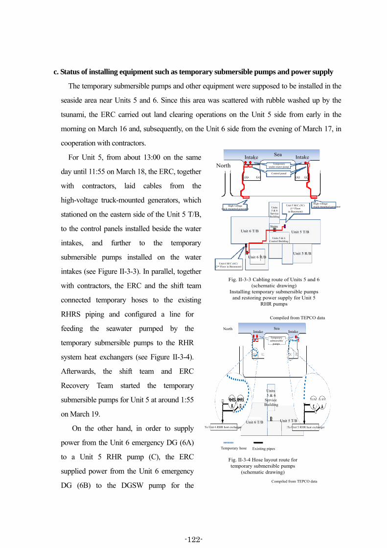
c. Status of installing equipment such as temporary submersible pumps and power supply
The temporary submersible pumps and other equipment were supposed to be installed in the
seaside area near Units 5 and 6. Since this area was scattered with rubble washed up by the
tsunami, the ERC carried out land clearing operations on the Unit 5 side from early in the
morning on March 16 and, subsequently, on the Unit 6 side from the evening of March 17, in
cooperation with contractors.
For Unit 5, from about 13:00 on the same
day until 11:55 on March 18, the ERC, together
with contractors, laid cables from the
high-voltage truck-mounted generators, which
stationed on the eastern side of the Unit 5 T/B,
to the control panels installed beside the water
intakes, and further to the temporary
submersible pumps installed on the water
intakes (see Figure II-3-3). In parallel, together
with contractors, the ERC and the shift team
connected temporary hoses to the existing
RHRS piping and configured a line for
feeding the seawater pumped by the
temporary submersible pumps to the RHR
system heat exchangers (see Figure II-3-4).
Afterwards, the shift team and ERC
Recovery Team started the temporary
submersible pumps for Unit 5 at around 1:55
on March 19.
On the other hand, in order to supply
power from the Unit 6 emergency DG (6A)
to a Unit 5 RHR pump (C), the ERC
supplied power from the Unit 6 emergency
DG (6B) to the DGSW pump for the
東京電力作成資料を基に作成
Compiled from TEPCO data
North
Unit 6 T/B Unit 5 T/B
Unit 6 M/C (6C)(2nd Floor in Basement)
Control panel
Unit 5 M/C (5C)(1st Floor
in Basement)
High voltagetruck-mounted generator
Unit 5 R/B
Units 5 & 6Control Building
Units5 & 6
ServiceBuilding
Stairs
High voltagetruck-mounted generator
Intake IntakeSea
Unit 6 R/B
Temporaryunder-water pump
Fig. II-3-3 Cabling route of Units 5 and 6 (schematic drawing)
Installing temporary submersible pumps and restoring power supply for Unit 5
RHR pumps
東京電力作成資料を基に作成
Compiled from TEPCO data
Unit 5 T/B
North
Temporary hose Existing pipes
Temporary submersible
pumps
:To Unit 5 RHR heat exchangerTo Unit 6 RHR heat exchanger
Unit 6 T/B
Intake IntakeSea
Units 5 & 6
Service Building
Fig. II-3-4 Hose layout route for temporary submersible pumps
(schematic drawing)
-122-

emergency DG (6A) by around 18:07 on March 18231. At about 19:07 on the same day, the
ERC confirmed that this DGSW pump was operational. In addition, together with contractors,
the ERC laid temporary cables from the Unit 6 M/C6C that was supplied with power from the
Unit 6 emergency DG (6A) to the load side of the Unit 5 M/C5C by around 14:00 on March 19.
The ERC also configured the line for supplying power from the Unit 6 emergency DG (6A) to
the Unit 5 RHR pump (C) (see Figure II-3-3)232. Afterwards, the shift team started the Unit 6
emergency DG (6A) and supplied power to the Unit 5 RHR pump (C) at around 4:22 on March
19 (see Attachment II-3-3).
For Unit 6, in the same way as it did for Unit 5, from that day onwards, the ERC and the shift
team worked together with contractors to lay cables from the high-voltage truck-mounted
generators stationed on the east side of the Unit 6 T/B to control panels, and further to the
temporary submersible pumps (see Figure II-3-3). They also configured the line for feeding the
seawater pumped by the temporary submersible pumps to the RHR system heat exchangers
(see Figure II-3-4), and started the temporary submersible pumps for Unit 6 at around 21:26 on
the same day.
d. Cooling the SFPs and reactors via the RHR systems
At Units 5 and 6, after the arrival of the tsunami, such plant conditions had persisted as the
RHR systems were unable to be operated and so cooling was unable to be carried out for either
the reactors or the SFPs.
As was described in (6) b., although the shift team replaced the SFP water at Unit 5 and
circulated the water through the FPC at Unit 6, these measures did nothing more than hold in
check the rise in the SFP water temperatures.
Furthermore, on the grounds that the SFP water inventory was larger than reactor water
inventory by comparison, the ERC concluded that it would be harder to reduce the SFP water
231 Power was supplied from a Unit 6 emergency DG (6B) via a Unit 6 P/C6C to a DG6AMCC6C-5 bearing the
power load for the DGSW pumps. Chapter II 3 (3) of the Interim Report said it was not clear whether the Unit 6 M/C6C had maintained its capability, citing the fact that it had not received power from the emergency DG. However, it is now believed that the Unit 6 M/C6C had maintained its capability because it had received power from the Unit 6 emergency DG (6A) at around 4:22 on March 19 without requiring any restoration work.
232 The 15 employees from the contractors laid and connected approximately 230 m length of cables. Furthermore, power was interconnected to the auxiliary systems of the Train A of the Unit 5 RHR system from the Unit 6 emergency DGs (6B) between around March 17 and March 18.
-123-
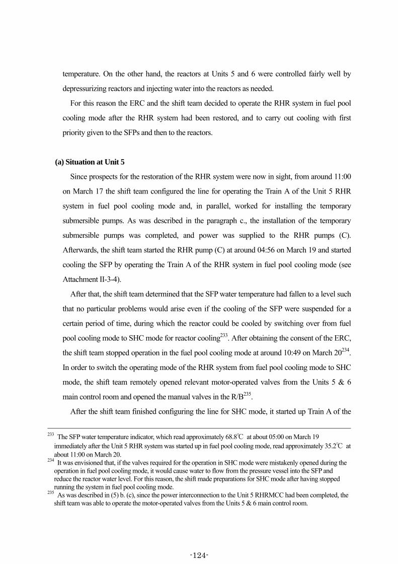
temperature. On the other hand, the reactors at Units 5 and 6 were controlled fairly well by
depressurizing reactors and injecting water into the reactors as needed.
For this reason the ERC and the shift team decided to operate the RHR system in fuel pool
cooling mode after the RHR system had been restored, and to carry out cooling with first
priority given to the SFPs and then to the reactors.
(a) Situation at Unit 5
Since prospects for the restoration of the RHR system were now in sight, from around 11:00
on March 17 the shift team configured the line for operating the Train A of the Unit 5 RHR
system in fuel pool cooling mode and, in parallel, worked for installing the temporary
submersible pumps. As was described in the paragraph c., the installation of the temporary
submersible pumps was completed, and power was supplied to the RHR pumps (C).
Afterwards, the shift team started the RHR pump (C) at around 04:56 on March 19 and started
cooling the SFP by operating the Train A of the RHR system in fuel pool cooling mode (see
Attachment II-3-4).
After that, the shift team determined that the SFP water temperature had fallen to a level such
that no particular problems would arise even if the cooling of the SFP were suspended for a
certain period of time, during which the reactor could be cooled by switching over from fuel
pool cooling mode to SHC mode for reactor cooling233. After obtaining the consent of the ERC,
the shift team stopped operation in the fuel pool cooling mode at around 10:49 on March 20234.
In order to switch the operating mode of the RHR system from fuel pool cooling mode to SHC
mode, the shift team remotely opened relevant motor-operated valves from the Units 5 & 6
main control room and opened the manual valves in the R/B235.
After the shift team finished configuring the line for SHC mode, it started up Train A of the
233 The SFP water temperature indicator, which read approximately 68.8℃ at about 05:00 on March 19
immediately after the Unit 5 RHR system was started up in fuel pool cooling mode, read approximately 35.2℃ at about 11:00 on March 20.
234 It was envisioned that, if the valves required for the operation in SHC mode were mistakenly opened during the operation in fuel pool cooling mode, it would cause water to flow from the pressure vessel into the SFP and reduce the reactor water level. For this reason, the shift made preparations for SHC mode after having stopped running the system in fuel pool cooling mode.
235 As was described in (5) b. (c), since the power interconnection to the Unit 5 RHRMCC had been completed, the shift team was able to operate the motor-operated valves from the Units 5 & 6 main control room.
-124-

RHR system in SHC mode and started cooling the reactor at around 12:25 on March 20 (see
Attachment II-3-4). Later on at around 14:30 that same day the reactor water temperature at
Unit 5 fell to under 100℃ and the reactor went into a cold shutdown.
(b) Situation at Unit 6
Starting at about 11:00 on March 19, the shift team configured the line for operating the Train
A of the Unit 6 RHR system in the fuel pool cooling mode. As was described in paragraph c.,
after the installation of the temporary submersible pumps was completed, the shift team started
up the RHR pump (B) at around 22:14 on March 19 and started cooling the SFP by operating
the Train A of the RHR system in fuel pool cooling mode (see Attachment II-3-5).
After that, the shift team determined that the SFP water temperature had fallen to a level such
that no particular problems would arise even if the cooling of the SFP were suspended for a
certain period of time, during which the reactor could be cooled by switching over from fuel
pool cooling mode to SHC mode. The shift team decided to switch the Unit 6 RHR system over
to SHC mode for cooling the reactor after the task of switching the operating mode for the Unit
5 RHR system was completed236. After obtaining the consent of the ERC, the shift team stopped
operation in the fuel pool cooling mode at around 16:26 on March 20237.
Afterwards, in order to switch the RHR system operating mode from fuel pool cooling mode
to SHC mode the shift team opened the required motor-operated valves from the Units 5 & 6
main control room.
The shift team then started up Train B of the RHR system in SHC mode and started cooling
the reactor at around 18:48 on March 20 (see Attachment II-3-5)238. Following this, at around
19:27 that same day the reactor water temperature at Unit 6 fell to under 100℃ and went into a
236 The shift supervisor instructed the shift team that work on Units 5 and 6 should not to be carried out concurrently,
unless it was an urgent work. As such, they were instructed to perform the task of switching the operating mode for the Unit 6 RHR system after completing the same task for the Unit 5 RHR system.
237 The Unit 6 SFP water temperature indicator, which read approximately 67.5℃ at about 22:00 on March 19 immediately before the Unit 6 RHR system was started up in fuel pool cooling mode, read approximately 27.5℃ at about 17:00 on March 20.
238 At around 17:40 on March 20, the reactor water level fell when the shift team started up Train B of the Unit 6 RHR system in SHC mode, so the shift team stopped the RHR system at about 17:45 that same day. The shift team believed that there was a possibility that water was flowing into the fuel pool cooling mode line, so they closed the motor-operated valves on the fuel pool cooling mode lines for the Unit 6 RHR system once more, while also closing the manual valves.
-125-
cold shutdown.
4. Restoration of External Power to the Fukushima Dai-ichi NPS
(1) Overview of the external power installations to the Fukushima Dai-ichi NPS
(i) Power generated at power stations is, through power lines, transformed and distributed at
substations which are the facilities to transform power voltage, and transmitted to systems and
facilities that consume power.
Usually, a part of power generated at the power station is used as power necessary for its
operation. However, when power lines that are only used for receiving power are installed, a
portion of power necessary for power station operation is supplied externally. In addition,
during periodic inspections and the period when power generation is shut down due to reasons
such as a reactor scram from any cause, power consumed inside the power station is supplied
externally.
(ii) Regarding external power received by the Fukushima Dai-ichi NPS, power at 275,000
volts was supposed to be supplied from the Shin-Fukushima Substation of Inawashiro Power
System Office of TEPCO (hereinafter called “Shin-Fukushima Substation”), located
approximately nine kilometers in the southwest of the Fukushima Dai-ichi NPS, through the
Okuma power transmission line No. 1 (hereinafter called “Okuma power line 1L”), the Okuma
power transmission line No. 2 (hereinafter called “Okuma power line 2L), the Okuma power
transmission line No. 3 (hereinafter called “Okuma power line 3L”), and the Okuma power
transmission line No. 4 (hereinafter called “Okuma power line 4L”), to Unit 1, Unit 2, Unit 3,
and Unit 4, respectively. Also, power at 66,000 volts was supposed to be supplied to Unit 5 and
Unit 6 from the Shin-Fukushima Substation through the Yonomori power transmission line No.
1 (hereinafter called “Yonomori power line 1L”) and the Yonomori power transmission line No.
2 (hereinafter called “Yonomori power line 2L”). In addition, power at 66,000 volts was
supposed to be supplied to Unit 1 through the TEPCO nuclear power line from the Tomioka
substation of the Tohoku Electric Power Company, Inc. (hereinafter called “Tohoku Electric
Power”) (see Attachment II-4-1).
Power transmitted to the Fukushima Dai-ichi NPS site is then supplied to the metal-clad
switchgears (M/C) installed in each unit via the on-site switchyards where devices such as
-126-

breakers and disconnecting switches are placed to switch the power paths239 in the site, and via
the startup installed at the Fukushima Dai-ichi NPS.
In concrete terms, power at 275,000 volts supplied through Okuma power line 1L and
Okuma power line 2L is supplied to each shared M/C240 for Unit 1 and Unit 2, via the Units 1
and 2 Ultra High Voltage Switchyard (hereinafter called “Units 1 & 2 Switchyard”), with
voltage stepped down to 6,900 volts by the startup transformers (STr1S and STr2S) installed in
the west side of each T/B for Unit 1 and Unit 2.
In addition, power at 275,000 volts supplied through Okuma power line 3L and Okuma
power line 4L is supplied to the shared M/Cs241 for Unit 3 and Unit 4, via the Units 3 and 4
Ultra High Voltage Switchyard (hereinafter called “Units 3 & 4 Switchyard”), with voltage
stepped down to 6,900 volts by the startup transformers (STr3SA and STr3SB) installed in the
west side of the Unit 3 T/B242.
Furthermore, power at 66,000 volts supplied through Yonomori power line 1L and
Yonomori power line 2L is supplied to the shared M/Cs243 for Unit 5 and Unit 6, via the 66kV
switchyard for Units 5 and 6 (hereinafter called “66kV switchyard”), with voltage stepped
down to 6,900 volts by the startup transformers (STr5SA and STr5SB) installed in the west side
of the C/B for Units 5 and 6.
Power at 66,000 volts supplied from the Tohoku Electric Power through the TEPCO nuclear
power line is supplied to the shared M/C for Unit 1, with voltage stepped down to 6,900 volts
by the transformer installed at the auxiliary substation at the Fukushima Dai-ichi site .
239 Power paths refer to the route of electricity from the point of generation to the point of consumption. In this
report, power paths refer to the route mainly from the bus bar in the Shin-Fukushima Substation to the generators and each load at the Fukushima Dai-ichi NPS site. Power is supplied to the bus bar of the Shin-Fukushima Substation from power generating stations or other substations, and accordingly many circuit breakers, disconnecting switches, and other devices, are installed in association with the bus bar.
240 The shared M/C is one of the normal M/Cs, which supplies received power to emergency M/Cs via normal M/Cs. The shared M/C1S for Unit 1 is installed on the first floor of the Unit 1 T/B. The shared M/C2SA for Unit 2 is installed on the first floor of its dedicated building located in the south of Unit 2 R/B, and the shared M/C2SB for Unit 2 is installed on the first basement of Unit 2 T/B.
241 The shared M/Cs for Unit 3 and Unit 4 (3SA and 3SB) are installed in the first basement of C/Bs at Unit 3 and Unit 4.
242 The circuit breakers and other devices for receiving power from the Okuma power line 3L at the Units 3 & 4 Switchyard were under construction. The circuit breakers and other devices for transmitting power to the Okuma power line 4L at the Units 3 and 4 Switchyard were also under construction.
243 The shared M/Cs for Unit 5 and Unit 6 (5SA-1, 5SA-2, 5SB-1 and 5SB-2) are installed in the first basement of the C/B for Units 5 and 6.
-127-

While each of the Okuma power lines was used not only for receiving external power but
also for transmitting power generated at Units 1 through 4 to the outside of the Fukushima
Dai-ichi site, each of the Yonomori power lines was only used for receiving power.
Power generated at Units 5 and 6 was transmitted to Shin-Fukushima Substation through
Futaba power transmission line No. 1 (hereinafter called “Futaba power line 1L”) and Futaba
power transmission line No. 2 (hereinafter called “Futaba power line 2L”), by way of the Units
5 and 6 Ultra High Voltage Switchyard (hereinafter called “Units 5 & 6 Switchyard).
Between the Shin-Fukushima Substation and Fukushima Dai-ichi NPS, the power
transmission lines in the same following group are supported by the same series of power line
towers: group 1 - Okuma power line 1L and Okuma power line 2L; group 2 - Okuma power
line 3L, Okuma power line 4L, Yonomori power line 1L, and Yonomori power line 2L; and
group 3 - Futaba power line 1L and Futaba power line 2L. In addition, within the Fukushima
Dai-ichi NPS site, the power transmission lines in the same following group are supported by
the same series of power line towers and connected to their respective switchyards: group f1 -
Okuma power line 1L and Okuma power line 2L; group f2 - Okuma power line 3L and Okuma
power line 4L; group f3 - Yonomori power line 1L and Yonomori power line 2L; and group f4
- Futaba power line 1L and Futaba power line 2L (see Attachments II-4-1 and II-4-2).
Hereafter, the series of power line towers that supports Okuma power line 3L, Okuma power
line 4L, Yonomori power line 1L, and Yonomori power line 2L is called the “Okuma Line
Tower,” and the series of power line towers that supports only Yonomori power line 1L and
Yonomori power line 2L within the Fukushima Dai-ichi NPS site is called the “Yonomori Line
Tower,” and the series of power line towers that support Futaba power line 1L and Futaba
power line 2L the called “Futaba Line Tower”244.
244 The Okuma Line Tower is comprised of 22 power line towers that are installed between the Shin-Fukushima
Substation and Fukushima Dai-ichi NPS and numbered, in the order of proximity to the Shin-Fukushima Substation, from Okuma Line Tower (No. 1) to Okuma Line Tower (No. 22). The Yonomori Line Tower is comprised of six towers installed within the Fukushima Dai-ichi NPS site, which are numbered, in the order of proximity to the Okuma Line Tower., from Yonomori Line Tower (No. 23) to Yonomori Line Tower (No. 28). The Futaba Line Tower is comprised of 33 towers that are installed between the Shin-Fukushima Substation and Fukushima Dai-ichi NPS site and numbered, in the order of proximity to the Units 5 & 6 Switchyard of the Fukushima Dai-ichi NPS, from Futaba Line Tower (No. 1) to Futaba Line Tower (No. 33). Between the Shin-Fukushima Substation and Fukushima Dai-ichi NPS, 27 towers are installed that support Okuma power line 1L and Okuma power line 2L.
-128-
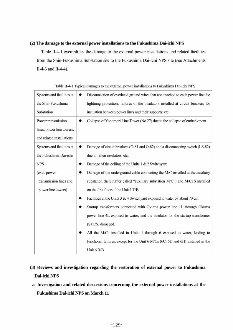
(2) The damage to the external power installations to the Fukushima Dai-ichi NPS
Table II-4-1 exemplifies the damage to the external power installations and related facilities
from the Shin-Fukushima Substation site to the Fukushima Dai-ichi NPS site (see Attachments
II-4-3 and II-4-4).
Table II-4-1 Typical damages to the external power installations to Fukushima Dai-ichi NPS
Systems and facilities at
the Shin-Fukushima
Substation
Disconnection of overhead ground wires that are attached to each power line for
lightning protection; failures of the insulators installed at circuit breakers for
insulation between power lines and their supports; etc.
Power transmission
lines, power line towers,
and related installations
Collapse of Yonomori Line Tower (No.27) due to the collapse of embankment.
Systems and facilities at
the Fukushima Dai-ichi
NPS
(excl. power
transmission lines and
power line towers)
Damage of circuit breakers (O-81 and O-82) and a disconnecting switch (LS-82)
due to fallen insulators, etc.
Damage of the ceiling of the Units 1 & 2 Switchyard
Damage of the underground cable connecting the M/C installed at the auxiliary
substation (hereinafter called “auxiliary substation M/C”) and M/C1S installed
on the first floor of the Unit 1 T/B
Facilities at the Units 3 & 4 Switchyard exposed to water by about 70 cm
Startup transformers connected with Okuma power line 1L through Okuma
power line 4L exposed to water; and the insulator for the startup transformer
(STr2S) damaged.
All the M/Cs installed in Units 1 through 6 exposed to water, leading to
functional failures, except for the Unit 6 M/Cs (6C, 6D and 6H) installed in the
Unit 6 R/B
(3) Reviews and investigation regarding the restoration of external power to Fukushima
Dai-ichi NPS
a. Investigation and related discussions concerning the external power installations at the
Fukushima Dai-ichi NPS on March 11
-129-
(i) Following the earthquake that occurred at around 14:46 on March 11, till around 14:49 on
the same day245, protection systems were actuated for Okuma power line 1L, Okuma power line
2L, Okuma power line 3L, Okuma power line 4L, Yonomori power line 1L, and Yonomori
power line 2L through which external power is supplied from the Shin-Fukushima Substation
to the Fukushima Dai-ichi NPS, resulted in the circuit breakers being opened and in the power
paths being interrupted246. It can be considered that the protection system actuation with regard
to Okuma power line 1L and Okuma power line 2L may have been caused by damaged circuit
breakers due to fallen insulators and others at the Fukushima Dai-ichi NPS. As for Okuma
power line 3L and Okuma power line 4L, it can be considered that the protection actuation may
have resulted from high-voltage discharge caused by the power transmission line swung to be
close enough to or contacting the power line tower due to seismic force. Regarding Yonomori
power line 1L and Yonomori power line 2L, it can be considered that the collapse of the
Yonomori Line Tower may have caused high-voltage discharge and other damage in the power
transmission line. As a result, the Fukushima Dai-ichi NPS became unable to receive external
power247.
(ii) The employees of TEPCO at the Shin-Fukushima Substation inspected the conditions of
the Shin-Fukushima Substation from around 15:00 on March 11, based on an emergency
response manual. Furthermore, from around 16:00 on the same day, the employees of
TEPCO’s Hamadori Power System Office (hereinafter called “Hamadori Power System
Office) visually checked, from the ground by car, the conditions of each power line of the
Okuma power lines installed from the Shin-Fukushima Substation to the Fukushima Dai-ichi
245 The time external power was lost is described based on the time on the Circuit Breaker Operation Supervisory
System of the Central Load Dispatching Office of TEPCO’s Head Office, and does not necessarily match each of the operation records of the Fukushima Dai-ichi NPS.
246 Power paths are equipped with protection systems in order to detect at an early stage the conditions of accidents such as lightning strikes on or accidental contacts at power supply facilities and power lines, for minimizing their effects. The protection systems include power line protection systems and generator protection systems that monitor their respective targets of monitoring. When abnormal electric current or voltage is detected in a power path within their respective scope of monitoring, actuation signals are sent to the circuit breakers from the protection system, resulting in the power path including the point of accident being isolated.
247 The loss of external power caused initiation of each of the emergency DGs at the Fukushima Dai-ichi NPS to supply emergency power to each Unit. Power transmission was also interrupted in the TEPCO nuclear power line because power transmission to the Tomioka Substation was interrupted at around 14:48 on March 11 as a result of the occurrence of high-voltage discharge in power lines due to seismic force. Afterward, Tohoku Electric Power restored the damage inside the Tomioka Substation as an emergency measure, and by around 19:00 on the same day, power transmission resumed with the TEPCO nuclear power line.
-130-

site including on-site installations, and the conditions of each power line of the Yonomori
power lines installed from the Shin-Fukushima Substation to the outside of the Fukushima
Dai-ichi NPS. At this point of time, however, the roads in the Fukushima Dai-ichi site near the
place where Yonomori Line Tower was installed were closed, so the employees of the
Hamadori Power System Office were unable to check the conditions of the Yonomori power
lines in the Fukushima Dai-ichi NPS site. Therefore, the employees of the Hamadori Power
System Office left the Shin-Fukushima Substation around slightly past 20:00 on the same day
in order to check the conditions of the Yonomori power lines in the Fukushima Dai-ichi NPS
site again. On the other hand, the Recovery Team of the NPS ERC checked the conditions of
the Units 1 & 2 Switchyard and the auxiliary substation from around 16:30 on the same day,
and the conditions of Units 3 & 4 Switchyard from around 20:30 on the same day. Table II-4-2
shows the main points that the TEPCO ERC had learned by the end of that day (see
Attachments II-4-3 and II-4-4).
The Transmission Recovery Team (hereinafter referred to as “Transmission Team”) and the
Distribution Recovery Team (hereinafter referred to as “Distribution Team”) of the TEPCO
ERC as well as the Nuclear Team gathered around the midnight of that day and shared the
information that each of them had obtained regarding external power for the Fukushima
Dai-ichi NPS248.
248 Until then, regarding matters including those related to external power for the Fukushima Dai-ichi NPS that had
been confirmed locally with each field, the TEPCO ERC’s Transmission Team, Distribution Team and Nuclear Team had been collecting information gained by other teams, through headquarter meetings, telephone, etc.
-131-

Table II-4-2 Confirmed conditions at the external power installations for Fukushima Dai-ichi NPS
Systems and facilities at
the Shin-Fukushima
Substation
Disconnection of overhead ground wires; failures of insulators; tilt of steel
structures supporting power lines; land subsidence, etc.249
Power transmission
lines, power line towers,
and related installations
Landslide near Yonomori Line Tower (No. 27)
Apparently no failure with power transmission with regard to the power lines
installed between the Shin-Fukushima Substation and each switchyard at the
Fukushima Dai-ichi NPS site
Systems and facilities at
the Fukushima Dai-ichi
NPS site
(excl. power
transmission lines and
power line towers)
Damage to circuit breakers (O-81 and O-82) and disconnecting switch (LS-82)
due to fallen insulators, etc.
Apparently no damage to the facilities of the auxiliary substation.
Devices of the Units 3 & 4 Switchyard (circuit breaker control panel) exposed to
water by about 70 cm
M/Cs installed in Units 1 and 2 exposed to water
Basement floor of T/B exposed to water, where the M/Cs for Units 3 and 4 are
installed
Also, at around 19:00 on the same day, the TEPCO ERC Nuclear Team was inquired by the
Tohoku Electric Power, through the TEPCO ERC Distribution Team, as to whether the TEPCO
nuclear power line should be charged. The TEPCO ERC Nuclear Team confirmed the site
conditions with the NPS ERC Recovery Team, and received the response that because M/C1S
with related cables that would receive power from the TEPCO nuclear power line were exposed
to water, it was not possible to receive power. Therefore, the TEPCO ERC Nuclear Team
249 The employees of the Shin-Fukushima Substation and subcontractors decided to commence work after midnight
on March 12 inside the Shin-Fukushima Substation, beginning with places that could be restored on a provisional basis. They fixed the tilted steel structures supporting Okuma power line 3L and Okuma power line 4L with wires, and fixed the broken overhead ground wires of Okuma power line 3L to the towers so that they would not interrupt their future work. In addition, by around the early evening of that day, at the Shin-Fukushima Substation, the employees of the Shin-Fukushima Substation and subcontractors removed the overhead ground wires of Okuma power line 3L that had been fixed to the steel structures. Furthermore, on March 16, inside the Shin-Fukushima Substation, the TEPCO ERC Transmission Team removed the power lines between the steel structures and Okuma Line Tower (No. 1) in order to lower the weight load imposed on the tilted steel structures supporting Okuma power line 3L and Okuma power line 4L.
-132-

replied to Tohoku-Electric Power, through the TEPCO ERC Distribution Team, that it was not
possible to receive power from the TEPCO nuclear power line.
(b) Review results regarding the restoration of external power to the Fukushima Dai-ichi
NPS after March 12 till the explosion at the Unit 3 R/B (see Attachments II-4-5 and 6)
(i) After midnight on March 12, the TEPCO ERC Transmission Team started reviews on
recovery plans on external power for Units 1 through 4, based on the information including the
damage to the external power installations. As for Yonomori Line Tower (No. 27), which is a
facility that supports Yonomori power line 1L and Yonomori power line 2L, it had been
estimated to have collapsed considering the surrounding circumstances, but it had not been
confirmed on-site yet. In addition, because the emergency DG for Unit 6 (6B) had been started
up, it was possible to supply power from Unit 6 to Unit 5. Therefore, the TEPCO ERC decided
that as to Units 5 and 6, power would be supplied from the emergency DG for Unit 6 (6B) for
the time being and that priority was given to the restoration of external power for Units 1
through 4.
(ii) First, TEPCO ERC determined that it was necessary to supply power to the P/C, which is
a power panel used for plant low-voltage loads of 480V, from power received at 66,000V at the
Fukushima Dai-ichi NPS site, voltage stepping down to 6,900V with a mobile transformer
within the site. Such decision was made through consideration to the following factors: a) the
circuit breakers and other devices were broken at the Unit 1 & 2 Switchyard, connected to the
startup transformers of Units 1 and 2; b) the Unit 4 startup transformer and the Unit 3 & 4
Switchyard were damaged with water, and there was no prospect for their restoration250; c) the
M/Cs for Units 1 through 4 were damaged with water and were not available251; and d) the
mobile transformer was not able to step down high-voltage power of 275,000 volts. In addition,
250 Unit 3 related facility was not available for use because the circuit breakers, etc. were under construction, which
had been connected to the startup transformers. 251 The TEPCO ERC Nuclear Team decided that it was necessary to connect power supplied externally directly to
the P/C because it had been confirmed that the M/Cs for Units 1 and 2 were unavailable as they were damaged with water. It was also estimated that the M/Cs for Units 3 and 4 were unavailable because the first basement of the T/B where the M/Cs were installed had been flooded. Afterward, by the end of March 12, the NPS ERC Recovery Team confirmed that many of the M/Cs installed for Units 3 through 6 were exposed to water.
-133-

the TEPCO ERC Nuclear Team decided to select Unit 4 P/C4D252 which had been installed on
the first floor of the T/B and may not have been exposed to water, as well as the Unit 2 P/C2C
that was available, as the P/Cs to which externally supplied power would be connected.
(iii) From around midnight to noon on March 12, based on the on-site conditions that had
been learned thus far, the TEPCO ERC Transmission Team considered a plan to supply power
externally to the Fukushima Dai-ichi NPS site at 66,000 volts by utilizing Yonomori power line
1L or Yonomori power line 2L, the power lines for 66,000 volts. In addition, because it had
become clear that the insulators and lightning arresters were damaged around Main
Transformer No.4253 that was connected to Yonomori power line 2L at the Shin-Fukushima
Substation, it was decided to utilize Yonomori power line 1L that was connected to Main
Transformer No.3 for which there was not much restoration work. Therefore, by around noon
on the same day, the TEPCO ERC Transmission Team proposed to the TEPCO ERC Nuclear
Team a plan to supply power by transmitting power to the Yonomori Line Tower near Units 5
and 6 in the Fukushima Dai-ichi NPS site by utilizing Yonomori power line 1L, and stepping
down the voltage to 6,900 volts with a mobile transformer (see Attachment II-4-5).
(iv) However, in order to use power supplied by this route as power supply for Units 1
through 4, it was necessary to install a temporary power line or cable for over 1km to P/C2C
and P/C4D. Therefore, the TEPCO ERC Nuclear Team requested the TEPCO ERC
Transmission Team to consider another plan that would enable the supply of power to places
near Units 1 through 4.
The power lines that had been installed and were the nearest to Units 1 through 4 at the
Fukushima Dai-ichi NPS site were Okuma power line 3L and Okuma power line 4L that were
connected to the Units 3 & 4 Switchyard (see Attachment II-4-2). The Okuma Line Tower
supported Okuma power line 3L and Okuma power line 4L jointly with Yonomori power line
1L, and Okuma power line 3L was the power line that was supported adjacently to Yonomori
power line 1L on the tower.
252 On the night of March 12, the NPS ERC Recovery Team confirmed that P/C4D was available for use. 253 At the Shin-Fukushima Substation, there are four main transformers that lower the voltage of 500,000 volts to
275,000 volts and 66,000 volts. Main Transformer No. 1 is connected to Okuma power line 1L; Main Transformer No. 2 is connected to Okuma power line 2L; Main Transformer No. 3 is connected to Okuma power line 3L and Yonomori power line 1L; and Main Transformer No.4 is connected to Okuma power line 4L and Yonomori power line 2L. Main Transformer No. 1 was under construction.
-134-

Therefore, in lieu of the plan that the TEPCO ERC Transmission Team had developed by
around noon on March 12 (see Attachment II-4-5), it developed a new plan by the end of the
same day. The new plan was to transmit power from the Shin-Fukushima Substation by
utilizing Yonomori power line 1L at 66,000 volts, and connect Yonomori power line 1L to
Okuma power line 3L at the Okuma Line Tower outside the Fukushima Dai-ichi NPS site
where power lines are jointly supported, and supply power to places near Units 1 through 4 (see
Attachment II-4-6). The TEPCO ERC Distribution Team and the Nuclear Team also approved
of this plan.
Afterward, the TEPCO ERC Transmission Team spoke about this plan at the TEPCO ERC
on the morning of March 13, and gained approval. After that date, the TEPCO ERC continued
to consider specific work procedures and other details.
c. Review results regarding the restoration of external power to the Fukushima Dai-ichi
NPS after the explosion at the Unit 3 R/B
(i) By the end of March 12, the TEPCO ERC Transmission Team had developed a plan to
install mobile transformers at the Fukushima Dai-ichi NPS site to lower the voltage of power
that had been supplied to Fukushima Dai-ichi NPS through Yonomori power line 1L via
Okuma power line 3L (hereinafter called “Yonomori/Okuma Connecting Line”) from 66,000
volts to 6,900 volts. However, at around 11:01 on March 14, due to the explosion at the Unit 3
R/B, debris of high radiation dose rate were scattered around the Units 3 & 4 Switchyard where
mobile transformers and other equipment were scheduled to be installed as part of this plan.
Starting around the early evening of that day, the TEPCO ERC Transmission Team learned that
it was extremely difficult to work on the spot due to the debris of high radiation dose rate
scattered about, and therefore, by late evening, the team changed the plan. The new plan was to
install mobile transformers in the Shin-Fukushima Substation with the aim of decreasing the
workload inside the Fukushima Dai-ichi NPS (see Attachment II-4-6).
(ii) On the other hand, due to the explosion at the Unit 3 R/B, radiation levels increased at the
site of work for power restoration using the Yonomori/Okuma Connecting Line. In addition,
with regard to the restoration of power by using a high-voltage truck mounted generator, which
had been carried out after March 11, it became difficult to find and install new materials and
-135-

equipment for the damaged high-voltage truck mounted generator and cables, and it was
estimated that much time would be needed to complete the work. Based on such circumstances,
it became necessary to consider a new restoration plan to supply power externally to Units 1
through 4.
Therefore, after around the evening of March 14, the TEPCO ERC Nuclear Team started to
consider the supply of external power via the TEPCO nuclear power line. At this point, the
TEPCO ERC Nuclear Team had decided to supply power to P/C2C and P/C4D by using either
the Yonomori/Okuma Connecting Line or the TEPCO nuclear power line, whichever would be
restored sooner.
Furthermore, as for the method to supply power to Units 5 and 6 externally through
Yonomori power line 2L, the TEPCO ERC Transmission Team was unable to develop a
concrete restoration plan as the site conditions near Yonomori Line Tower (No. 27) had not
been confirmed. Power to be used by Units 5 and 6 was supplied by Unit 6 Emergency DG
(6B).
(iii) Around the early evening of March 15, at the TEPCO ERC conference, the TEPCO ERC
Nuclear Team explained the plan to restore external power that it had developed by then, as well
as the site conditions. Because there was the possibility of Unit 6 Emergency DG (6B) that was
in operation stopping as aftershocks continued, the TEPCO ERC instructed to continue work
for the restoration of all the three routes of the TEPCO nuclear power line, Yonomori/Okuma
Connecting Line, and Yonomori power line 2L, and restore them as quickly as possible.
As the involved parties moved forward with consideration based on this decision, there was a
prospect of simultaneous restoration of the TEPCO nuclear power line and Yonomori/Okuma
Connecting Line by around the evening of March 16. Therefore, the TEPCO ERC Nuclear
Team decided which power line would be utilized to supply external power to each unit; that is,
to supply power from the TEPCO nuclear line to Units 1 and 2, from the Yonomori/Okuma
Connecting Line to Units 3 and 4, and from Yonomori power line 2L to Units 5 and 6, and
continued to consider the details in concrete terms. The progress of restoration regarding
external power will be explained below for each of the restoration routes.
-136-

(4) Restoration progress of external power to the Fukushima Dai-ichi NPS
a. Restoration progress of external power to the Units 1 and 2 (see Attachment II-4-7)
(i) As explained in (3) c above, from around the night of March 14 to the early morning of
March 15, the TEPCO ERC Nuclear Team decided on a restoration plan to supply power at
66,000 volts to the auxiliary substation through the TEPCO nuclear power line, and lower the
voltage to 6,900 volts with the transformer installed in the auxiliary substation to supply power.
In addition, around the evening of March 16, the TEPCO ERC Nuclear Team decided to
connect to P/C2C the power supplied via this route as power supply for Units 1 and 2.
(ii) First, in considering the method of supplying power through the TEPCO nuclear power
line, on the morning of March 15, the TEPCO ERC Distribution Team, which received a
request from the TEPCO ERC Nuclear Team, requested Tohoku Electric Power to charge the
TEPCO nuclear power line up to the auxiliary substation. At around 09:45 on the same day,
Tohoku Electric Power confirmed that it was possible to charge the lines up to the disconnecting
switch installed inside the auxiliary substation. Afterward, by noon on March 16, the TEPCO
ERC Transmission Team confirmed that the equipment installed between the disconnecting
switch installed in the auxiliary substation and the auxiliary substation M/C could be used.
(iii) By around dawn on March 16, the NPS ERC Recovery Team measured the insulation
resistance to confirm whether the cables buried underground from the auxiliary substation M/C
to M/C1S which was installed in the Unit 1 T/B could be used254. As a result, it became clear
that the cables from the auxiliary substation M/C to M/C1S were damaged. Because it would
require time to identify the damaged part as the cables were buried underground, the TEPCO
ERC Nuclear Team gave up the idea of utilizing the already installed cables, and decided to
install cables from the auxiliary substation M/C to the M/C temporarily installed on the road
inside the site in the north of Unit 1 T/B (hereinafter called “Units 1 & 2 Temporary M/C”)255.
However, the auxiliary substation where the auxiliary substation M/C was installed was on the
hill which was at least 30m above the O.P., and there was a large difference of altitude between
the substation and the Units 1 & 2 Temporary M/C which was scheduled to be installed near
254 The TEPCO ERC Nuclear Team had determined that it would not be possible to use the underground cables that
had been exposed to water on March 11, but considered the possibility of using the cables after they become dry, and measured the insulation resistance.
255 The TEPCO ERC Nuclear Team procured four M/Cs to be installed temporarily from the contractor.
-137-

Unit 1 R/B placed at about 12m above the O.P. Therefore, it was difficult to connect the
auxiliary substation M/C and the Units 1 & 2 Temporary M/C by taking the shortest way, and
by around late evening on the same day, the TEPCO ERC Nuclear Team decided to install
temporary cables for about 1.5 km along the road in the site from the auxiliary substation M/C
to the Units 1 & 2 Temporary M/C.
(iv) After March 17, the TEPCO ERC Distribution Team, the Nuclear Team, NPS ERC
Recovery Team and the contractors engaged in work such as the removal of debris from the
cable routes, the installation of the cables and the restoration of hydraulic pressure of circuit
breakers in the auxiliary substation256. Then the receipt of power was completed at the Units 1
& 2 Temporary M/C and P/C2C at around 15:37 and around 15:46 on March 20, respectively.
Between March 12 and the afternoon of March 14, it became necessary to evacuate the site
because of preparatory work for PCV venting at Units 1 through 3 and also because work
environment there deteriorated following the explosion at the R/Bs of Units 1 and 3. Evacuation
also became necessary on March 17 and the afternoon of March 18 due to the influence of
water spraying on the SFP. In addition, because there were times when the postponement of
work was unavoidable due to frequent aftershocks, much time was required for the work for the
restoration of power.
b. Restoration progress of external power to the Units 3 and 4 (see Attachment II-4-8)
(i) As explained in (3) b and c, based on the damage due to the earthquake and the influence
of the explosion at the Unit 3 R/B, the TEPCO ERC Transmission Team decided on March 14
to supply power after lowering the voltage to 6,900 volts with mobile transformers at the
Shin-Fukushima Substation to the inside of the Fukushima Dai-ichi NPS via the
Yonomori/Okuma Connecting Line. In addition, around the evening of March 16, the TEPCO
ERC decided to install a compact prefabricated substation257 (hereinafter called “mobile
256 Hydraulic pressure is necessary to operate the switching device of a circuit breaker. When the conditions of the
auxiliary substation had been checked on the night of March 11, it had been confirmed that there had still remained hydraulic pressure in the circuit breakers, but there was no hydraulic pressure left after the loss of power to maintain hydraulic pressure for a few days. Therefore, the TEPCO ERC Nuclear Team actuated the oil pump with a small generator and restored hydraulic pressure.
257 The compact prefabricated substation is a compact substation system which contains devices necessary for switching such as circuit breakers and protective devices placed in one cubicle.
-138-
compact substation”), which includes switchgears for power paths, as well as a multiple-circuit
switchgear258 inside the Fukushima Dai-ichi NPS site, and connect power supplied via these
devices to P/C4D in order to supply power for Units 3 and 4.
On the other hand, the TEPCO ERC Transmission Team had started to procure mobile
transformers259. This is because from around midnight on March 11, the TEPCO ERC
Transmission Team shared information with the TEPCO ERC Nuclear Team and Distribution
Team at the TEPCO Head Office, and learned that each of the startup transformers connected to
Okuma power lines 1L to 4L had been submerged in water and the circuit breakers had been
damaged at the switchyards, among other facts.
(ii) As part of the work for the restoration of external power through the Yonomori/Okuma
Connecting Line, the TEPCO ERC Transmission Team and contractors first decided to confirm
whether there was any damage on the cables of Yonomori power line 1L which had been buried
under the places where land subsidence had occurred in the Shin-Fukushima Substation site.
Shortly after 02:00 on March 14, the TEPCO ERC Transmission Team and others confirmed at
the Shin-Fukushima Substation that it was possible to charge the cables to the cable head, which
is a processed terminal assembly to fit cable connection.
From the afternoon of March 15, the TEPCO ERC Transmission Team and the employees of
contractors started the work to connect Yonomori power line 1L and Okuma power line 3L that
were supported jointly by Okuma Line Towers (No.7 and No.8) installed outside the
Fukushima Dai-ichi NPS site, and completed the work by shortly after 23:00 on the same day.
As the line towers on which to carry out this work for connection, Okuma Line Towers (No.7
and No.8) were selected for the following reasons: a) there was not much inflection of the
power lines around the line tower; b) it was easy to carry out the work for connection as there
was not much swinging motion of the power lines because they were pulled at two points and
supported by the line towers; and c) the premises around the line tower were suitable for the
258 The multiple-circuit switchgear is a switching device to distribute power to multiple circuits. Protective devices
are not embedded in the multiple-circuit switchgear. 259 Because the Shin-Fukushima Substation is a facility with the main aim of transmitting and receiving power to
and from power stations and substations, and it was not expected to supply low-voltage power of 6,900 volts around the substation; it was not always equipped with mobile transformers. Therefore, the TEPCO ERC Transmission Team procured mobile transformers from other substations and power system offices, etc.
-139-
carrying in and installation of equipment260,261.
In addition, on the afternoon of March 16, the TEPCO ERC Transmission Team and the
employees of contractors started to install mobile transformers near the cable heads of
Yonomori power line 1L inside the premises the Shin-Fukushima Substation, and connected
them to the cable heads. The TEPCO ERC Transmission Team and others also installed a
mobile compact substation in the southwestern side of the Units 3 & 4 Switchyard and
connected it to Okuma power line 3L in the Fukushima Dai-ichi NPS site, and on March 18
confirmed that it was possible to charge the line up to the mobile compact substation.
In the early hours of March 19, after the Self-Defense Forces and the Tokyo Fire Department
completed the water spraying on the SFP, the TEPCO ERC Distribution Team, together with
contractors, installed a multiple-circuit switchgear in the southwestern side of the Units 3 & 4
Switchyard, and installed cables from the mobile compact substation to the multiple-circuit
switchgear. In addition, after March 20, after confirming the installation route of the cables from
the multiple-circuit switchgear to P/C4D, the TEPCO ERC Nuclear Team, together with
contractors and NPS ERC Recovery Team, worked to install and connect the cables, and on
March 22, the receipt of external power was completed up to P/C4D.
Between March 12 to the afternoon of March 14, it became necessary to evacuate the site
because of preparatory work for PCV venting at Units 1 to 3 and also because work
environment there deteriorated following the explosion at the R/Bs of Units 1 and 3. Evacuation
also became necessary on March 17 and the afternoon of March 18 due to the influence of
260 In alternating-current (AC) power, the direction and amplitude of electric voltage and current change at a
constant frequency; the method in which AC power is transmitted in three directions (phases) separately through respective power lines is called three-phase AC. This is a power transmission method that is currently frequently used. Due to the feature of this method, one power line is in effect divided into three lines (three phases), and connecting work is necessary for each of the three (three-phase) power lines in order to interconnect the power paths. For the connection from Yonomori power line 1L to Okuma power line 3L, one phase was connected at the line tower (No. 7) and two phases were connected at the line tower (No. 8). In addition, power lines were connected at points where the jumper cables were supported. Jumper cables refer to the part where separate power paths are interconnected, and can be used, for example, to detour around the places near power transmission towers in order to prevent power lines from contacting the towers.
261 As part of the work to connect Yonomori power line 1L and Okuma power line 3L, from around 18:00 on March 14, the TEPCO ERC Transmission Team and the employees of the contractor removed the jumper cables of Yonomori Line 1L at the line tower (No. 12) which was installed closer to the Fukushima Dai-ichi NPS than the line tower on which it was scheduled to connect the Yonomori power lines and the Okuma power lines, in order to disconnect unnecessary power paths. On March 16, the TEPCO ERC Transmission Team and others also removed the jumper cables of Okuma power line 3L at the line tower (No. 3) installed outside the premises of the Shin-Fukushima Substation to disconnect unnecessary power paths.
-140-

water spraying on the SFP. In addition, because there were times when the postponement of
work was unavoidable due to frequent aftershocks, much time was required for the work for the
restoration of power.
c. Restoration progress of external power to the Units 5 and 6 (see Attachment II-4-9)
(i) Although power had been supplied to Units 5 and 6 from the Unit 6 Emergency DG (6B),
as explained in (3) c above, around the evening of March 15, the TEPCO ERC decided to
restore Yonomori power line 2L as quickly as possible. Therefore, the TEPCO ERC
Transmission Team decided to supply power of 66,000 volts from the Shin-Fukushima
Substation through Yonomori power line 2L, lower the voltage to 6,900 volts with the existing
startup transformer (STr5SA), and supply power to M/C6C and M/C6D which had been
confirmed to be in good conditions262.
Furthermore, inside the premises of the Fukushima Dai-ichi NPS, because Yonomori Line
Tower (No.27) had collapsed, it was necessary to transmit power by detouring around the
places near this tower. The TEPCO ERC Transmission Team had originally considered
temporarily installing steel poles near the collapsed tower for restoration. However, due to
increase in radiation levels in the work site and the necessity to evacuate from the work site
because of the water spraying to the SFP, they had not been able to conduct sufficient
investigation of the site to install steel poles. Later, the TEPCO ERC Transmission Team
confirmed the site on March 17, and found that a large number of temporary steel poles were
necessary and that further investigation of the site was required. The TEPCO ERC
Transmission Team therefore abandoned the idea of installing temporary steel poles given the
necessity to shorten the time spent on work to be carried out on-site. The TEPCO ERC
Transmission Team then decided to temporarily install power lines from the Yonomori Line
Tower (No.26) to the Yonomori Line Tower (No.28), using the Futaba Line Tower (No.2)
which had been confirmed to be in good conditions to support the power cables, by detouring
around the places near the collapsed tower.
262 It was stated in Chapter II 3 (3) b of the Interim Report that it was unknown whether the function of M/C6C was
maintained as power was not received from the Emergency DG. However, M/C6C was used in the work for the restoration of external power, and consequently its function was maintained.
-141-

However, when power cables were to be temporarily installed at the Yonomori Line Tower
(No.26) from Yonomori power line 2L toward the Futaba Line Tower (No.2), there was a risk of
the temporary power cables approaching Yonomori power line 1L causing a short circuit
because Yonomori power line 1L was supported closer to the Futaba Line Tower (No.2) than
Yonomori power line 2L. Therefore, the TEPCO ERC Transmission Team decided to use
Yonomori power line 1L for transmission from the Yonomori Line Tower (No.26) to the 66kV
switchyard and the Futaba Line Tower (No.2) to support the power cables after connecting
Yonomori power line 2L to Yonomori power line 1L at the Yonomori Line Tower (No.26), and
then to connect to Yonomori power line 1L again at the Yonomori Line Tower (No.28).
(ii) On March 17, the TEPCO ERC Nuclear Team, together with contractors and the NPS
ERC Recovery Team, started to confirm the conditions of devices such as circuit breakers
installed at the 66kV switchyard, and restored hydraulic pressure necessary for the switching
operation of the circuit breaker (O-51) by March 19. In addition, in order to detour around the
M/C that was damaged by water and could not be used and to connect to M/C6C and M/C6D,
the TEPCO ERC Nuclear Team and others installed temporary cables to M/C6C and M/C6D
from the primary side of the M/C that was connected to the startup transformer (STr5SA).
Furthermore, insulation was necessary to ensure a physical clearance between the temporary
power cables and nearby trees with the aim of preventing accidents in which the cables to be
installed would contact or come too close to the trees. Therefore, the TEPCO ERC
Transmission Team and the contractor cut down the trees between the line towers from March
18 to 20. Following this, the TEPCO ERC Transmission Team and others connected the power
lines to the Yonomori Line Tower (No.28) from the Yonomori Line Tower (No.26) via the
Futaba Line Tower (No.2)263. Also, the TEPCO ERC Transmission Team confirmed that it was
possible to charge the power cables up to the disconnecting switch (LS-51) of Yonomori power
line 1L installed at the 66kV switchyard. In addition, inside the premises of the Shin-Fukushima
Substation, parts of the disconnecting switch of Yonomori power line 2L were out of alignment,
263 Because the foundation part of Yonomori Line Tower (No. 28) was deformed due to the collapse of Yonomori
Line Tower (No. 27), the TEPCO ERC Transmission Team fixed the leg part with wires. Also, because the detoured supporting of power lines imposed load on Yonomori Line Towers (No. 26 and No. 28) and Futaba Line Tower (No. 2) in a direction that was different from usual, the team fixed these towers with stays in order to prevent tilting and collapse.
-142-

and the insulators installed between Main Transformer No.4 and the circuit breakers were
damaged. Therefore, the TEPCO ERC Transmission Team and the employees of contractors
repaired them on March 18.
Then external power was received by M/C6C and M/C6D around 11:36 on March 21, and
around 19:17 on March 22, respectively.
On March 17 and the afternoon of March 18, much time was required for the work for the
restoration of power because evacuation from the work site became necessary due to the effect
of water spraying on the SFP and because there were times when the frequent aftershocks
forced the work to be postponed.
(5) Stabilization of external power to be supplied to the Fukushima Dai-ichi NPS
(i) As explained in (4) above, by March 22, external power was supplied to Units 1 and 2
through the TEPCO nuclear line, to Units 3 and 4 through the Yonomori/Okuma Connecting
Line, and to Units 5 and 6 through the Yonomori power line 2L (see Attachments II-4-7 to
II-4-9). In parallel with this restoration work, TEPCO-ERC Nuclear Team, NPS ERC Recovery
Team and the employees of contractors interconnected M/Cs that were used for the restoration
of external power so that it would be possible to use power received from other power lines in
case the receipt of power from one power line stopped at the Fukushima Dai-ichi NPS site.
Afterward, TEPCO ERC also considered plans and worked on-site in order to supply
external power to the Fukushima Dai-ichi NPS in a more stable manner264 (see Attachment
II-4-10).
(ii) In concrete terms, regarding external power to be supplied through the Yonomori/Okuma
Connecting Line, in order to increase receiving power capacity and raise electric voltage
(66,000 volts)265, TEPCO ERC installed mobile transformers on the Fukushima Dai-ichi NPS
264 The power received was used for facilities such as instrumentation systems, reactor cooling facilities, and water
treatment systems. 265 As explained in (3) c above, the original plan was to install mobile transformers at the Fukushima Dai-ichi NPS
site, and supply power at 66,000 volts to the Fukushima Dai-ichi NPS site. Also, because it was expected that power consumption at the Fukushima Dai-chi NPS site would increase due to the operation of facilities for treating stagnant water in the buildings, etc., it was necessary to increase receiving power. Because receiving power capacity depends on the capacity of mobile transformers, it was also required to install more mobile transformers. If more mobile transformers were to be installed inside the Shin-Fukushima Substation, it would be necessary to install power lines to the Fukushima Dai-ichi NPS, and therefore the TEPCO ERC Transmission
-143-
site by April 29, and increased the number of mobile transformers on the Fukushima Dai-ichi
NPS site by May 16. This doubled receiving power through the Yonomori/Okuma Connecting
Line and made it possible to supply external power at high-voltage (66,000 volts) in a more
stable manner.
(iii) Furthermore, in late March, the TEPCO ERC was also considering measures to stabilize
external power supply by capitalizing on existing installations. As the TEPCO ERC learned that
it was possible to use the circuit breakers and transformers installed at the Units 1 & 2
Switchyard for the shared house boiler266, the TEPCO ERC had work conducted to detour
around the damaged breakers and to install devices such as mobile transformers267, among other
activities. As a result, it became possible to supply power of 275,000 volts through Okuma
power line 2L by May 10268.
(iv) Regarding Yonomori power line 2L that transmitted power to Units 5 and 6, the TEPCO
ERC Transmission Team was considering a method to supply power in a more stable manner
utilizing the existing installations, given the following and other factors: a) the Yonomori Line
Towers (No.26 and No.28) and the Futaba Line Tower (No.2) were supported by stays in order
to support the weight of newly installed power lines or cables, and b) the power lines that was
detoured to and supported by the Futaba Line Tower (No.2) inside the Fukushima Dai-ichi NPS
site did not have a lightning protection function269. Therefore, the TEPCO ERC Transmission
Team decided to supply power through the Futaba power lines that had been installed to
Team decided to install more mobile transformers at the Fukushima Dai-ichi NPS site. It was also necessary to install lightning arresters on the side of the Fukushima Dai-ichi NPS in the power path of Yonomori/Okuma Connecting Line, but higher electric voltage (66,000 volts) was necessary as the lightning arresters were for 66,000 volts.
266 The transformer for the shared house boiler is a device to lower voltage of 275,000 volts to 66,000 volts, which is used to supply power to the shared house boiler for heating devices, etc., of Units 1 through 4.
267 The mobile transformers are to lower voltage to 6,900 volts from 66,000 volts that was transformed with the transformers for shared house boiler.
268 The TEPCO ERC also considered utilizing Okuma power line 1L and the startup transformer connected to it (STr1S). However, because damage in the ceiling was confirmed in the upper part of the place where Okuma power line 1L was installed at the Units 1 & 2 Switchyard, the TEPCO ERC decided to utilize Okuma power line 2L to restore more stable paths. It was difficult to perform any restoration work on the startup transformer connected to Okuma power line 2L (STr2S) as damage was confirmed in the insulator in the place where the power lines were supported, and also because of high radiation levels in the place where STr2S was installed.
269 Paragraph 7, Article 59 of the Practical Details of Technical Standards for Electrical Installations stipulates that power transmission line towers should not use stays for load sharing under normal circumstances. Therefore, the TEPCO ERC considered a method in which towers supported by stays would not be used, considering the possibility of transmitting power over a long period of time.
-144-

transmit power. By July 22, the TEPCO ERC Transmission Team connected Yonomori power
line 1L and Yonomori power line 2L to Futaba power line 1L and Futaba power line 2L,
respectively, at the Shin-Fukushima Substation and the Fukushima Dai-ichi NPS site, and
performed other work. Consequently, power began to be supplied to the 66kV switchyard
through two power lines by utilizing these existing facilities.
(v) Furthermore, by March 2012, TEPCO cut down on the utilization of temporary
installations through such means as the new installation of a 66kV switchyard in the southern
side of the Unit 1 & 2 Switchyard and the commencement of the receipt of power through
Okuma power line 4L270. Ever since then, TEPCO has been committed to take further
stabilization measures such as the new installation of bus bars at the Shin-Fukushima
Substation.
5. Response to the Accident at the Fukushima Dai-ni Nuclear Power Station
(1) Outline of the response to the accident at the Fukushima Dai-ni Nuclear Power Station
On March 11, 2011, the Tohoku District - off the Pacific Ocean Earthquake occurred, and a
tsunami caused by the earthquake reached the Fukushima Dai-ni Nuclear Power Station
(hereafter “Fukushima Dai-ni NPS”). In contrast to the Fukushima Dai-ichi NPS, the provision
of external power continued at the Fukushima Dai-ni NPS, even after the arrival of the tsunami.
Owing to this, it was possible at the Fukushima Dai-ni NPS to grasp the plant conditions
through various monitoring devices, and operations for plant control was able to continue, such
as reactor depressurization and water injection into the reactor, without particular recovery
measures.
However, the RHRs could not be activated at the Fukushima Dai-ni NPS, due to the damage
to the emergency seawater pumps and power supply panels, excluding one train of Unit 3. Until
the RHRs were restored, the reactor water levels were maintained by water injection into the
reactor, in order to avoid uncovering the fuel. All units were thus brought down to cold
270 By performing work to connect Yonomori power line 1L and Yonomori power line 2L with Okuma power line
3L and Okuma power line 4L, respectively, at the Shin-Fukushima Substation, power was transmitted to the Fukushima Dai-ichi NPS site through Okuma power line 3L and Okuma power line 4L, which was then connected to the newly installed bus bars of the 66kV switchyard at the Fukushima Dai-ichi NPS site. Power supplied through the TEPCO nuclear power line was also connected to the newly installed bus bars of the 66kV switchyard.
-145-

shutdown by March 15, 2011 (see Attachment II-5-1).
(2) Outline of the Fukushima Dai-ni NPS
a. Overview of the facilities and history of construction
The Fukushima Dai-ni NPS is located in Naraha Town and Tomioka Town, both in Futaba
County, Fukushima Prefecture, and is approximately 12km to the south of the Fukushima
Dai-ichi NPS. The site is almost square, and its eastern side borders the Pacific Ocean. The total
area of the site is approximately 1.47 Million m2, including an area of approximately 200,000
m2 reclaimed from the sea.
The Fukushima Dai-ni NPS is a nuclear power station constructed and operated by TEPCO.
Since the construction of Unit 1 began in November, 1975, other units were gradually added,
and it currently has four boiling water reactor units. Unit 1 started operation in April 1982. The
current total generating capacity of Units 1 through 4 is 4,400 MW in electricity. The
specifications of each unit are given in Attachment II-5-2.
b. Facilities layout and structure
(a) Overview
Units 1 and 2 are situated in Naraha Town, Futaba County, Fukushima Prefecture, and Units
3 and 4 are situated in Tomioka Town in the same county.
Each unit is composed of the R/B, T/B, C/B, service building, RW/B, the Seawater Heat
Exchange Equipment Building (Hx/B), etc. Some of these buildings are shared with the
adjacent unit. The general layout of these buildings is seen in Attachment II-5-3.
The R/Bs, T/Bs, C/Bs, service buildings and RW/Bs are situated in the main building
installation area, at O.P.+12m, and the Hx/Bs are situated in the seaward area at O.P.+4m.
(b) Structure of the R/B
In contrast to Units 1 to 5 of the Fukushima Dai-ichi NPS, the Fukushima Dai-ni NPS
employs a compound R/B system, in which the reactor sector and the annex form an integral
configuration, constructed on the same basement slab. The reactor pressure vessel, primary
containment vessel, and SFP are installed in the reactor sector, whereas the Emergency DGs,
-146-
Emergency M/Cs, P/Cs271, etc. are installed in the annex.
(c) Structure of the Hx/B
At the Fukushima Dai-ni NPS, an Hx/B is constructed on the eastern seaward area of the T/B
of each unit (O.P+4m). It comprises of two floors above ground and one floor below ground,
and the heat exchangers and seawater pumps etc. are installed in the building. Specifically, the
emergency seawater pumps such as those of the Residual Heat Removal Equipment Cooling
System (RHRC)272, RHR Sea Water System (RHRS)273, Emergency Equipment Cooling Water
System (EECW)274, as well as the P/Cs that supply power to these pumps are installed in the
Hx/B.
At the Fukushima Dai-ichi NPS, seawater pumps are installed on the seaward area to pump
up seawater, and circulate that seawater through piping directly into the heat exchangers, etc. in
the R/B for decay heat removal and equipment cooling. In contrast, at the Fukushima Dai-ni
NPS, the pumped-up seawater is not circulated directly to the heat exchangers in the R/B. An
intermediate loop for fresh water circulation is added between the seawater and the R/B, and the
seawater exchanges heat with this new freshwater loop. Thus installed in the Hx/B, seawater
does not directly go into the R/B (see Figure II-5-1).
271 Emergency P/Cs that supply power to the emergency seawater pumps are installed in the Hx/B. 272 The RHRC is the system that supplies cooling water to the RHR heat exchangers, and cools the RHR pumps,
the low-pressure core spray system pumps, etc. 273 The RHRS is the system that supplies seawater to cool the RHR cooling water. 274 The EECW is the system that supplies freshwater for cooling the Emergency DGs, the emergency
air-conditioning equipment, etc. so that the duty functions of emergency equipment can be maintained in an accident including a loss-of-coolant accident. It also supplies cooling water to the RHR pump motors.
-147-
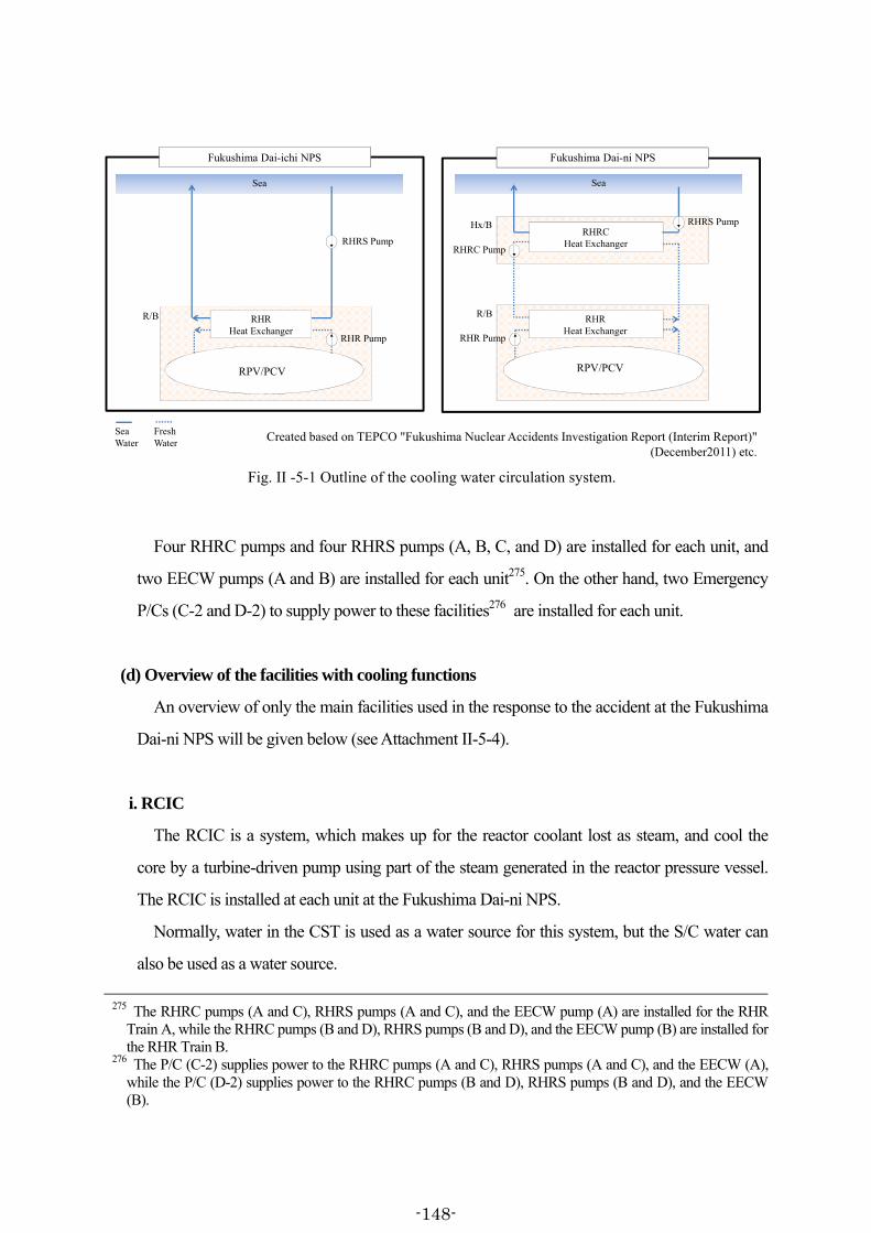
RHRHeat Exchanger
Fukushima Dai-ichi NPS
RPV/PCV
RHRS Pump
R/B
RHR Pump
Sea Water
Fresh Water
Fukushima Dai-ni NPS
RHRCHeat Exchanger
RHRHeat Exchanger
RHRS Pump
RPV/PCV
Hx/B
RHRC Pump
R/B
RHR Pump
Sea Sea
Created based on TEPCO "Fukushima Nuclear Accidents Investigation Report (Interim Report)" (December2011) etc.
Fig. II -5-1 Outline of the cooling water circulation system.
Four RHRC pumps and four RHRS pumps (A, B, C, and D) are installed for each unit, and
two EECW pumps (A and B) are installed for each unit275. On the other hand, two Emergency
P/Cs (C-2 and D-2) to supply power to these facilities276 are installed for each unit.
(d) Overview of the facilities with cooling functions
An overview of only the main facilities used in the response to the accident at the Fukushima
Dai-ni NPS will be given below (see Attachment II-5-4).
i. RCIC
The RCIC is a system, which makes up for the reactor coolant lost as steam, and cool the
core by a turbine-driven pump using part of the steam generated in the reactor pressure vessel.
The RCIC is installed at each unit at the Fukushima Dai-ni NPS.
Normally, water in the CST is used as a water source for this system, but the S/C water can
also be used as a water source.
275 The RHRC pumps (A and C), RHRS pumps (A and C), and the EECW pump (A) are installed for the RHR
Train A, while the RHRC pumps (B and D), RHRS pumps (B and D), and the EECW pump (B) are installed for the RHR Train B.
276 The P/C (C-2) supplies power to the RHRC pumps (A and C), RHRS pumps (A and C), and the EECW (A), while the P/C (D-2) supplies power to the RHRC pumps (B and D), RHRS pumps (B and D), and the EECW (B).
-148-

ii. MUWC
The MUWC supplies water necessary for operating reactor facilities, with the CST as its
water source and using the condensate water transfer pump. The MUWC is installed at each
unit at the Fukushima Dai-ni NPS.
The connection of the piping between the MUWC and RHR was changed, and the
originally-installed manually-operated valve between the two systems was changed to a
motor-operated one to enable remote operation from the main control room (MCR), so that
water injection from the MUWC to the reactor be allowed through the RHR, as part of accident
management development. At the Fukushima Dai-ni NPS, these motor-operated valves have
been installed on the piping connecting the MUWC and RHR Train A at each unit.
iii. High Pressure Core Spray System (HPCS)
The HPCS sprays water onto the fuel using the motor-operated high-pressure pump and
cools the core, in a loss-of-coolant accident due to, for instance, a pipe rupture. The HPCS is
installed at each unit at the Fukushima Dai-ni NPS.
Normally, the water source is the CST, but the S/C water can also be used as its water source.
iv. RHR
The RHR is a system, which cools the reactor coolant after the reactor is shut down, with an
aim of removing decay heat while the reactor is at shutdown. The RHR is installed at each unit
at the Fukushima Dai-ni NPS. The operation mode of the RHR can be changed by a valve
switchover maneuver, and when necessary in an emergency, it can also inject water into the
reactor. The specific operation modes are the SHC mode, low pressure injection mode,
containment vessel spray mode, S/C cooling mode, and Fuel Pool Cooling mode.
It is necessary to activate the RHRC pumps, RHRS pumps and EECW pumps, which have
functions to supply cooling water to the heat exchangers and to cool the RHR pumps etc. when
the RHR is used for cooling the reactor coolant and others.
(3) The damage at the Fukushima Dai-ni NPS
a. External power supplies
-149-

The external power to the Fukushima Dai-ni NPS are normally received via a total of four
power transmission lines, composed of the Tomioka power transmission line No. 1 and line No.
2 (hereinafter “Tomioka power line 1L” or “Tomioka power line 2L” respectively, and
“Tomioka power lines 1L and 2L” collectively), and the Iwaido power transmission line No. 1
and line No. 2 (hereinafter “Iwaido power line 1L” or “Iwaido power line 2L” respectively, and
“Iwaido power lines 1L and 2L” collectively).
On March 11, the day of the earthquake, the reception of power via the Iwaido power line 1L
was in suspension due to a periodic inspection, and therefore the incoming power was received
through three transmission power lines: the Tomioka power lines 1L and 2L and the Iwaido
power line 2L.
At approximately 14:48 on the same day, immediately after the earthquake occurred, the
reception of power via the Tomioka power line 2L was lost due to damage to a disconnecting
switch at the Shin-Fukushima Substation, located approximately 7 km to the north-west of the
Fukushima Dai-ni NPS. Furthermore, a patrol check at the Shin-Fukushima Substation after the
earthquake identified damage to a lightning arrester of the Iwaido power line 2L, and so the
reception of power via the Iwaido power line 2L was lost at approximately 15:50 on the same
day.
Consequently, the external power to the Fukushima Dai-ni NPS was possible only through a
single transmission power line of Tomioka power line 1L. However, the Iwaido power line 2L
was restored by approximately 13:38 on March 12, and the Iwaido power line 1L was restored
by around 05:15 on March 13, recovering the power reception consisting of these three
transmission power lines (see Attachment II-5-5).
b. The Tsunami that reached the Fukushima Dai-ni NPS
(a) Inundation on the seaward area
The first wave from the tsunami caused by the Tohoku District - off the Pacific Ocean
Earthquake reached the Fukushima Dai-ni NPS at approximately 15:22 on March 11, and
waves continued to hit intermittently. The seaward area (O.P. +4m) of the Fukushima Dai-ni
NPS was completely inundated due to the tsunamis.
The inundation height of the seaward area was O.P. + approximately 7.0 m to approximately
-150-
8.9 m (the inundation depth of approximately 2.8 m to approximately 4.3 m), and on the south
side of the same area, a localized inundation height of O.P. + approximately 12.6 m (the
inundation depth of approximately 8.6 m) was observed (see Attachment II-5-6).
As described in (2) b. (c) above, the Hx/B of each unit was installed on the seaward area, and
each Hx/B was inundated by the tsunami, and the first underground floor of each was flooded.
Moreover, it can be judged from the inundation marks that the first floors of each unit's Hx/B
were inundated to a level of 2 meters or more above the floor level, excepting the southern part
of the Unit 3 Hx/B, whereas no inundation marks were observed on the second floors,
excepting the southern part of Unit 1 Hx/B.
(b) Inundation on the main building construction area
The tsunami did not cross the slope of the main building construction area (O.P. +12 m), and
run up from the seaward area, but there a was concentrated run-up on the road running east to
west on the south side of Unit 1, where a large volume of water swept around from the Unit 1
side to the direction of Unit 2.
The inundation height around Unit 1 was O.P.+ approximately 12.4 m to approximately 15.9
m (the inundation depth of approximately 0.2 m to 4.1 m), and this inundation was observed on
the Unit 1 R/B, T/B, charcoal building, Units 1 & 2 service building (see Attachment II-5-6).
Regarding from Units 2 to 4, the inundation height around the buildings was O.P. +
approximately 11.9 m to approximately 12.9 m (the inundation depth of approximately 0.1 m to
approximately 1.0 m), even though the tsunami swept around from the side of Unit 1. Almost
no inundation into the buildings was observed apart from the Units3 T/B, Units 3 & 4 service
building and charcoal buildings.
c. The station power supplies after the tsunami
(a) The emergency DGs
The tsunami that hit the Fukushima Dai-ni NPS caused a concentrated run-up on the road
running east to west on the south side of Unit 1, and inundated the Unit 1 R/B.
Three Emergency DGs had been installed on the second underground floor of the annex of
-151-
the Unit 1 R/B (1A, 1B, and 1H277), all of which lost their functions due to water damage. The
Emergency DGs of other units escaped water damage themselves, but the seawater pumps to
cool the Emergency DGs had lost their functions due to the tsunami. Consequently, with the
exception of two Emergency DGs of Unit 3 (3B and 3H), and one Emergency DG of Unit 4
(4H), all other Emergency DGs were unable to be activated (see Attachment II-5-7, Table 1).
(b) The emergency M/Cs
There are three Emergency M/Cs at each unit, being C, D, and H278, and they are installed on
the first underground floor of the R/B annex.
At the tsunami, the Unit 1 Emergency M/Cs (1C and 1H) lost their functions due to water
damage, but at other units power was available to the Emergency M/Cs (see Attachment II-5-7,
Table 2).
(c) The emergency P/Cs installed in the R/B annex
Two Emergency P/Cs (C-1 and D-1) are installed on the first underground floor of each R/B
annex.
At the tsunami, the Unit 1 Emergency P/C (1C-1) lost its functions due to water damage,
but power was available to other Emergency P/Cs (see Attachment II-5-7, Table 3).
There are also two P/Cs installed in the Hx/Bs that supply power to the seawater pumps etc.
(See (3) d. (b) below for the Emergency P/Cs installed in the Hx/Bs).
(d) Wrap-up
Although the Emergency DGs at the Fukushima Dai-ni NPS were (with some exceptions)
unable to activate, the external power continued to be received after the tsunami, and power
supply from the Emergency DGs was not essentially needed.
At Unit 1, the Emergency M/C (1C) and the Emergency P/C (1C-1) suffered water damage
from the tsunami and lost their functions. Consequently, the AC power supply Train A was lost,
277 The Emergency DG (H) of each unit is installed to provide power to the HPCS and the seawater pumps for its
cooling. 278 The Emergency M/C (H) of each unit is installed to provide power to the HPCS and the seawater pumps for its
cooling.
-152-

and the DC power for Train A became dependent on power from emergency batteries279.
Concerning Units 2 to 4, the Emergency M/Cs, and the Emergency P/Cs installed in the R/B
annex, escaped damage, and both AC power and DC power were maintained.
d. The emergency seawater pumps and power supply panels
At the Fukushima Dai-ni NPS, the RHR became unable, with the exception of one train of
Unit 3, to activate because the inundation in the Hx/B of each unit damaged the RHRC pumps,
RHRS pumps, EECW pumps and most P/Cs that supplied power to these pumps.
The following describes the damage to the RHRC pumps, RHRS pumps, EECW pumps, and
the P/Cs that supply power to these pumps.
(a) The emergency seawater pumps (RHRC, RHRS and EECW)
As explained in (2) b. (c) above, there are four RHRC pumps and four RHRS pumps, being
A, B, C, and D of each, installed on each unit. In addition, there are two EECW pumps, A and B,
installed on each unit.
The Hx/B of each unit is comprised of two floors above ground and one floor below ground.
The RHRC pumps (2A, 2B, 2C, and 2D) and the EECW pump (2B) of Unit 2, and the EECW
pump (4B) of Unit 4 are installed on the second floor280, and the other emergency seawater
pumps are all installed on the first floor.
The tsunami that hit the Fukushima Dai-ni NPS completely inundated the seaward area, and
the Hx/B of each unit was also inundated. The first underground floor of the Hx/B of each unit
was flooded, and the first floors seem to have been inundated by over 2 m from the floor level,
excepting the south side area of the Unit 3 Hx/B, based on the inundation marks.
The following pumps lost their functions due to water damage to motors from the tsunami:
RHRC pumps (1A, 1B, 1C, and 1D) and EECW pumps (1A and 1B) of Unit 1, RHRS pumps
(2A, 2C, and 2D) and EECW pump (2A) of Unit 2, RHRC pumps (3A and 3C) and EECW
279 The power supply from emergency batteries ended when the DC 125V was switched over to the reserve
battery charger at approximately 17:35 on March 11, and the DC 250V was switched over to the reserve battery charger at approximately 18:05 on the same day, respectively.
280 These pumps were installed on the second floor, simply because no sufficient space for installation was available on the first floor of the Hx/B, not because of a precaution for a tsunami.
-153-

pump (3A) of Unit 3, and RHRC pumps (4A, 4B, 4C, and 4D), RHRS pumps (4A, 4B, and 4C)
and EECW pump (4A) of Unit 4. (See Table II-5-1 and Attachment II-5-8)
北側 南側 北側 南側 北側 南側 北側 南側
△ RHRC(A) △ RHRC(B)
△ RHRC(C) △ RHRC(D)
△ EECW(B) △ EECW(B)
△ RHRS(B) △ RHRS(A) × RHRS(A) △ RHRS(B) △ RHRS(A) ○ RHRS(B) × RHRS(A) × RHRS(B)
△ RHRS(D) △ RHRS(C) × RHRS(C) × RHRS(D) △ RHRS(C) ○ RHRS(D) × RHRS(C) △ RHRS(D)
× RHRC(B) × RHRC(A) × RHRC(A) ○ RHRC(B) × RHRC(A) × RHRC(B)
× RHRC(D) × RHRC(C) × RHRC(C) ○ RHRC(D) × RHRC(C) × RHRC(D)
× EECW(B) × EECW(A) × EECW(A) × EECW(A) ○ EECW(B) × EECW(A)
北側 南側 北側 南側 北側 南側 北側 南側
1階 × P/C1D-2 × P/C1C-2 × P/C2C-2 × P/C2D-2 × P/C3C-2 ○ P/C3D-2 × P/C4C-2 × P/C4D-2
設置場所
1号機 2号機 3号機 4号機
○:使用可能 ×:被水したため機能喪失
2階
1階
非常用P/C
海水ポンプ(RHRC、RHRS及びEECW)
設置場所
1号機 2号機 3号機 4号機
○:使用可能 △:電源盤が被水したため機能喪失 ×:電源盤及びモーターが被水したため機能喪失
Table II-5-1 The damage to emergency seawater pumps and emergency P/Cs in the Hx/B due to the tsunami
Created based on TEPCO "Fukushima Nuclear Power Stations Accident Investigation Report (Interim Report)" (December2011).
Seawater pumps (RHRC, RHRS, and EECW) OperableFunction lost due to submerged power supply panel
Function lost due to submerged power supply panel and motor
Unit 1 Unit 2 Unit 3 Unit 4
Unit 1 Unit 2 Unit 3 Unit 4
1st floor
2nd floor
Installed location
North Side North Side South Side North Side South Side North Side South Side
P/CFunction lost due to submersion
1st floor
North Side South Side North Side South Side North Side South Side North Side South Side
Installed location
Operable
South Side
(b) The emergency P/Cs installed in the Hx/B
As explained in (2) b. (c) above, two Emergency P/Cs (C-2 and D-2) are installed on the first
floor of the Hx/B of each unit and supply power to the RHRC pumps, RHRS pumps, and
EECW pump.
All these Emergency P/Cs lost their functions due to water damage from the tsunami,
excepting the P/C (3D-2) installed on the first floor of the southern area of Unit 3 Hx/B (see
Table II-5-1 and Attachment II-5-7).
(4) Response from the occurrence of earthquakes to the arrival of tsunami (between
approximately 14:46 on March 11 and approximately 15:22 on the same day)
a. Operation conditions of each unit of the Fukushima Dai-ni NPS immediately before the
occurrence of earthquakes
All units, from 1 to 4, at the Fukushima Dai-ni NPS were in stationary operation at rated
thermal power. The recorder chart of each unit shows, as given in Table II-5-2, the reactor
-154-
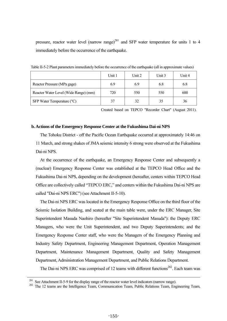
pressure, reactor water level (narrow range)281 and SFP water temperature for units 1 to 4
immediately before the occurrence of the earthquake.
Table II-5-2 Plant parameters immediately before the occurrence of the earthquake (all in approximate values)
Unit 1 Unit 2 Unit 3 Unit 4
Reactor Pressure (MPa gage) 6.9 6.9 6.8 6.8
Reactor Water Level (Wide Range) (mm) 720 550 550 600
SFP Water Temperature (°C) 37 32 35 36
Created based on TEPCO "Recorder Chart" (August 2011).
b. Actions of the Emergency Response Center at the Fukushima Dai-ni NPS
The Tohoku District - off the Pacific Ocean Earthquake occurred at approximately 14:46 on
11 March, and strong shakes of JMA seismic intensity 6 strong were observed at the Fukushima
Dai-ni NPS.
At the occurrence of the earthquake, an Emergency Response Center and subsequently a
(nuclear) Emergency Response Center was established at the TEPCO Head Office and the
Fukushima Dai-ni NPS, depending on the development (hereafter, centers within TEPCO Head
Office are collectively called “TEPCO ERC,” and centers within the Fukushima Dai-ni NPS are
called "Dai-ni NPS ERC") (see Attachment II-5-10).
The Dai-ni NPS ERC was located in the Emergency Response Office on the third floor of the
Seismic Isolation Building, and seated at the main table were, under the ERC Manager, Site
Superintendent Masuda Naohiro (hereafter "Site Superintendent Masuda"): the Deputy ERC
Managers, who were the Unit Superintendent, and two Deputy Superintendents; and the
Emergency Response Center staff, who were the Managers of the Emergency Planning and
Industry Safety Department, Engineering Management Department, Operation Management
Department, Maintenance Management Department, Quality and Safety Management
Department, Administration Management Department, and Public Relations Department.
The Dai-ni NPS ERC was comprised of 12 teams with different functions282. Each team was
281 See Attachment II-5-9 for the display range of the reactor water level indicators (narrow range). 282 The 12 teams are the Intelligence Team, Communication Team, Public Relations Team, Engineering Team,
-155-

stationed at a booth set up at the rear of the main table, and arranged so that information could
be communicated verbally between the main table and each team's booth (see Attachment
II-5-11). In addition, the TEPCO ERC members could listen to the contents of discussions at the
main table of the Dai-ni NPS ERC, through a television conference system, offer suggestions or
ask questions etc. to the Dai-ni NPS ERC, thus facilitating the sharing of information between
both ERCs.
The Dai-ni NPS ERC ascertained information, via television broadcasts, such as tsunami
warnings along the Fukushima coastline, the estimated arrival time and anticipated height of the
tsunami, etc., and provided that information to each MCR.
From the occurrence of the earthquake, Site Superintendent Masuda was concerned about
that a tsunami would hit the Fukushima Dai-ni NPS. He instructed his staff to watch, from the
third-floor terrace of the Seismic Isolation Building, the tsunami arrival, and also instructed the
frontline workers to leave the spot. Meanwhile, the Operation Management Department
Manager dispatched two information-liaison personnel283 from the Dai-ni NPS ERC Operation
Team to each MCR in order to promptly ascertain plant information. The Operation Team
received periodic reports from the information-liaison personnel dispatched to each MCR
regarding plant parameters of each unit, summarized it into graphs etc., and shared that
information with the whole Dai-ni NPS ERC members.
Health Physics Team, Recovery Team, Operation Team, Procurement Team, Infrastructure Team, Medical Treatment Team, General Affairs Team and Guard-Guidance Team. The team leader is a group manager in respective departments. However, the Public Relations Team is headed by the Public Relations Department Manager who is a member of the NPS ERC, and the Recovery Team is led by the Maintenance Department Manager who is also a member of the NPS ERC, respectively.
283 The information liaison personnel mainly collected key plant information at the Main Control Room, and communicated with the Operation Team on the information, and also provided support to the shift supervisors.
-156-

c. Actions in each MCR
(a) Outline
At the time that the earthquake occurred, all units at the Fukushima Dai-ni NPS were in
stationary operation at rated thermal power, and the shift teams284 at the MCR for Unit 1 and
Unit 2 (hereafter the "Units 1 & 2 MCR"), and the MCR for Unit 3 and Unit 4 (hereafter the
“Units 3 & 4 MCR”) were on duty in operation of nuclear power facilities (see Figure II-5-2).
After the earthquake, the
shift team on duty in each
MCR continued to be the
main player in reactor
operation and other tasks.
Other shift teams off duty
also went to each MCR for
support as needed, or were
on standby at the Seismic
Isolation Building. They alternated shift duties in subsequent days.
At the Fukushima Dai-ni NPS, the plant operating response in such a situation is such that, in
principle, the shift supervisor made necessary decisions in accordance with the “Fukushima
Dai-ni Nuclear Power Station Nuclear Operator Emergency Management Operation Plan.”
Exceptionally when conducting operations that required co-ordination with other units, or
conducting operations which would have a large effect on plant behavior, the shift supervisor
looked to the Dai-ni NPS ERC for suggestions/instructions, and the Dai-ni NPS ERC gave
suggestions/instructions to the shift supervisor.
Even when the shift team was not looking for suggestions or instructions, the shift supervisor
etc. continually reported the basic information necessary for reactor control, as it becomes
available, to the Dai-ni NPS ERC Operation Team by his PHS mobile phone.
284 A shift team is comprised of a total of 10 members (one shift supervisor, one assistant shift supervisor, two
senior operators, one assistant senior operator, two main equipment operators and three auxiliary equipment shift operators). Five such teams operate on shift the nuclear power facilities 24 hours a day.
Fig. II-5-2 Shift team structure at Fukushima Dai-ni Nuclear Power Station
Created based on TEPCO "Fukushima Dai-ni Nuclear Power Station Unit 3 Fukushima Dai-ni Nuclear Power Station Unit 4
Periodic Safety Review (Second Implementation) Report"
Power station site superintendent
Unit superintendent
Operation Management Department Manager
Team for Units 1 & 2
Team for Units 3 & 4
One senior operator and one main equipment operator are assigned to each plant. The number of staff on each shift varies depending on the plant conditions.
Shift supervisor(1)
Assistant shift supervisor(1)
Shift supervisor(1)
Assistant shift supervisor (1)
Assistant senior operator(1)
Assistant senior operator(1)
Senior operators(2)
Senior operators(2)
Main equipment operators(2)
Main equipment operators(2)
Auxiliary equipment operators (3)
Auxiliary equipment operators(3)
-157-

(b) Actions in the Units 1 & 2 MCR
Directly after the earthquake occurred, the shift team in the Units 1 & 2 MCR was closely
watching the annunciators up on the control panels in preparation for the reactor's automatic
scram (see Figure II-5-3), while
securing their own safety.
At approximately 14:48 on
March 11, the shift team confirmed
on the displays of the control
panels in the MCR that all control
rods had been inserted into Unit 1
and Unit 2 and that the reactors
had automatically scrammed. The
shift supervisor reported this to the
Operation Management
Department Manager by his PHS
mobile phone.
Subsequently, the shift team, upon instructions of the shift supervisor, began to control the
reactor pressure by transporting the high-temperature and high-pressure steam in the reactor
from the Main Steam Piping to the Main Condenser through the Turbine Bypass Valve, and
returning the condensate back to the reactor via the Feedwater/Condensate Supply System285.
When the earthquake's shaking subsided, the shift supervisor contacted by his PHS mobile
the shift team members that had been working in the R/B, T/B, etc., and told them to check their
personnel and return to the MCR.
At approximately 14:48 on the same day, the power via the Tomioka power line 2L was
suspended, due to damage to a disconnecting switch at the Shin-Fukushima Substation, but the
power continued to be received via the two lines of the Tomioka power line 1L and Iwaido
power line 2L.
285 At all units (Units 1 through 4) of the Fukushima Dai-ni NPS, the main condensers were available for reactor
pressure control, because the main steam isolation valves were not closed at the earthquake. The situation is different from that of the Fukushima Dai-ichi NPS Units 1-3 where all external AC power sources were lost.
Alarm typer
Fig. II-5-3 Layout of Units 1&2 MCRCreated based on TEPCO-Created Materials
Main machine operator
Main machine operator
Shift manager
Alarm typer
Shift supervisor
Deputy shift supervisor
Shift manager
Unit 2Deputy shift managerAuxiliary machine operator Unit 1
-158-

(c) Actions in the Units 3 & 4 MCR
Directly after the earthquake occurred, the shift team in the Units 3 & 4 MCR was closely
watching the annunciators up on the control panels in preparation for the reactor's automatic
scram (see Figure II-5-4), while
securing their own safety.
At approximately 14:48 on March
11, the shift team confirmed on the
displays of the control panels that all
control rods had been inserted into
Unit 3 and Unit 4 and that the
reactors had automatically scrammed.
The shift supervisor reported this to
the Operation Management
Department Manager by his PHS
mobile phone.
Subsequently, the shift team, upon
instructions of the shift supervisor, began to control the reactor pressure by transporting the
high-temperature and high-pressure steam in the reactor from the Main Steam Piping to the
Main Condenser through the Turbine Bypass Valve, and returning the condensate back to the
reactor via the Feedwater/Condensate Supply System286.
When the earthquake's shaking subsided, the shift supervisor told, using the paging etc. his
shift team members on patrol etc. in the buildings to check their personnel and return to the
MCR.
At approximately 14:48 on the same day, the power via the Tomioka power line 2L was
suspended, as with Units 1 and 2, due to damage to a disconnecting switch at the
Shin-Fukushima Substation, but the power continued to be received via the two transmission
power lines of the Tomioka power line 1L and Iwaido power line 2L.
286 See Footnote 285.
Fig. II-5-4 Layout of Units 3&4 MCRCreated based on TEPCO-Created Materials
Alarm typerShift manager
Main machine operator
Shift manager
Main machine operator
Deputy shift supervisor
Shift supervisor
Alarm typer
Deputy shift managerAuxiliary machine operator
Unit 4 Unit 3
-159-

(5) Response after the arrival of tsunami on March 11 (after approximately 15:22 on March
11)
a. Actions at the Dai-ni NPS ERC
(a) Power cut and recovery at the Emergency Response Office
Tsunamis hit the Fukushima Dai-ni NPS intermittently since approximately 15:22 on March
11.
The tsunami that hit the Fukushima Dai-ni NPS caused a concentrated run-up on the road
running east to west on the south side of Unit 1, and reached the first floor of the Seismic
Isolation Building. This led to the loss of the function of the power distribution panel installed in
the power supply room on the first floor of the Seismic Isolation Building, and consequently the
power was cut in the Emergency Response Office, the room lighting went out, and
communication with the TEPCO ERC etc. through the television conference system was lost.
Site Superintendent Masuda instructed the Dai-ni NPS ERC Recovery Team to urgently
restore power supply to the Emergency Response Office. The Dai-ni NPS ERC Recovery Team,
with the assistance of a contractor, laid a cable from the power distribution panel installed in the
first underground floor of the Administration Building to the lighting power distribution panel
(100V) next to the Emergency Response Office, and between about 18:00 and 19:00 on the
same day, restored power supply to the Emergency Response Office. The communication with
the TEPCO ERC through the television conference system was thus restored.
In the meantime, since the fixed telephone line was in service during the power cut, the
Dai-ni NPS ERC kept contact with the TEPCO ERC using the fixed-line telephones while the
television conference system was unavailable.
(b) Notification of the occurrence of a specific event (reactor coolant leakage) at Unit 1
pursuant to the provisions of Article 10, Paragraph 1 of the Act on Special Measures
Concerning Nuclear Emergency Preparedness
At approximately 17:35 on March 11, the Operation Management Department Manager
received a report from the shift supervisor in the Units 1 & 2 MCR that “a ‘high D/W pressure’
warning was actuated at Unit 1, and a ‘Main Steam Isolation Valve (MSIV) low reactor water
level (L-2)’ had been recorded at 15:37 upon checking the alarm typer.”
-160-

The Operation Management Department Manager understood that the possibility of reactor
coolant leakage in the D/W could not be denied, since an “MSIV low reactor water level (L-2)”
signal was being actuated in addition to the “high D/W pressure” signal, even though he did not
confirm on the reactor water level indicator that the reactor water level had decreased to L-2287.
He therefore believed it desirable to issue a notification of a specific event (reactor coolant
leakage) pursuant to the provisions of Article10 Paragraph 1 of the Act on Special Measures
Concerning Nuclear Emergency Preparedness (hereafter the “Nuclear Emergency Preparedness
Act”), and advised as such to Site Superintendent Masuda.
Upon receipt of this, Site Superintendent Masuda instructed the Dai-ni NPS ERC
Communication Team to issue the notification pursuant to Article 10 Paragraph 1 of the Nuclear
Emergency Preparedness Act. At approximately 17:50 on the same day, the notification was
sent to the relevant authorities.
Subsequently, the Dai-ni NPS ERC adjudged by approximately 18:33 on the same day that
the reactor coolant had not leaked, by confirming on the CAMS that the radiation level had not
been rising, and notified the relevant authorities accordingly.
(c) Notification of the occurrence of a specific event pursuant to the Provisions of Article 10
Paragraph 1 of the Nuclear Emergency Preparedness Act (Loss of heat removal function)
(Unit 1, Unit 2 and Unit 4)
Directly after the tsunami, the Dai-ni NPS ERC received reports from the shift supervisors in
the Units 1 & 2 MCR and Units 3 & 4 MCR that the RHRs on Units 1, 2 and 4 were unable to
activate due to the effects of the tsunami, and in response the Dai-ni NPS ERC reviewed the
287 When the reactor water level lowers to L-2 (on Unit 1, meaning the level of -966mm on the reactor water level
indicator (wide range)), that information is communicated to the logic circuit, and the current that flows in that logic circuit is cut. The system is set up so that, when the logic circuit current is lost, a solenoid coil (an electromagnetic relay) mounted on the current controller is de-energized, the coil terminal contacts the terminal of a circuit which signals a process computer to type an MSIV low reactor water level (L-2) signal, and the "MSIV low reactor water level (L-2)" is recorded on the alarm typer. This logic circuit works by the plant vital power source, but when the M/C (1C) suffered water damage from the tsunami, the plant vital power supply A, downstream from it, was lost. The current was supposed to be lost when the reactor water level lowered to L-2, but it was lost when the tsunami waves killed the plant-vital power source A. It can be thought that this led the solenoid coil terminal to contact the logic circuit terminal which signaled the computer to type the “MSIV low reactor water level (L-2)” on the alarm typer, before the reactor water level actually lowered to L-2 (see Attachments II-5-12).
-161-
situations of the RHRs of Unit 1, Unit 2 and Unit 4. At this time, the Hx/B damage had not
actually been confirmed on-site, but as a result of discussion, Site Superintendent Masuda
believed that it would not be possible to immediately restore the RHRs, considering that the
status indicator lamps of the emergency seawater pumps of Unit 1, Unit 2 and Unit 4 had been
out on the control panels, and also in consideration of the scale of the tsunami and other factors.
He adjudged that these circumstances constituted a specific event (loss of heat removal
function) pursuant to the provisions of Article 10, Paragraph 1 of the Nuclear Emergency
Preparedness Act, and at approximately 18:49 on March 11, he notified this to the relevant
authorities.
(d) Checks of the damage in the buildings
After the tsunami, Site Superintendent Masuda did not forthwith direct his team to check the
damage of the power supply panels, various equipment, etc. of the R/Bs, T/Bs, and Hx/Bs, etc.,
because of frequent aftershocks and risk of another tsunami hitting, although he had been aware
of the need to check the damage.
A while later, Site Superintendent Masuda instructed the Dai-ni NPS ERC Recovery Team at
approximately 20:00 on March 11 to check the damage of the R/Bs and T/Bs first, believing
that, in view of a risk to human life upon another tsunami, the R/Bs and the T/Bs of the main
building construction area would be safer than the Hx/Bs in the seaward area.
Upon this instruction, the electrical equipment group of the Dai-ni NPS ERC Recovery Team
formed three patrol teams for checking inside the R/B, inside the T/B and inside the Hx/B,
respectively, with the support of contractors.
From after around 20:00 on the same day, the patrol teams to check inside the R/B and T/B
departed first to check the damage in those buildings. As a result, it gradually became clear that,
regarding Unit 1, the room on the second underground floor of the R/B annex, where the
Emergency DG had been installed, had been inundated, that the M/C (1C) and P/C (1C-1)
installed on the first underground floor of the R/B annex had been flooded, and other status.
After around 22:00 on the same day, upon instruction of Site Superintendent Masuda the
Hx/B patrol team checked the damage inside the Hx/B. Those at the Dai-ni NPS ERC were
worried that another tsunami might hit while the patrol team was on patrol inside the Hx/B.
-162-
Therefore, while they watched the direction to the sea with the monitors in the Dai-ni NPS ERC,
they made arrangements so that the patrol team on-site maintained the PHS mobile phone
communication for any time contact with the members of the Dai-ni NPS ERC Recovery Team.
With the progress of such patrols for checking the damage, it became clear that the first
underground floors of the Hx/B of each unit had been flooded, and that the first floors also had
had inundation marks exceeding the height of the P/C288. Whereas, on the southern part in the
Unit 3 Hx/B, it became clear that water entry had been only to the extent of the flooring of the
first floor being slightly wet.
The results of these patrol checks were continually reported to the Dai-ni NPS ERC by PHS
mobile phones by the patrol team that had made for the checks, and were shared at the Dai-ni
NPS ERC by writing up the damage on a whiteboard by the Recovery Team.
b. Actions in each MCR directly after the arrival of tsunami
(a) Actions in the Units 1 & 2 MCR
At Unit 1, due to the effects of the tsunami, the Emergency DGs289 (1A, 1B, and 1H)
installed on the second underground floor of the R/B annex, and the Emergency M/Cs (1C and
1H) installed on the first underground floor of the R/B annex suffered water damage, in addition
to other facilities in the Hx/B in the seaward area. At Unit 1, the external power was being
received through Tomioka power line 1L and Iwaido power line 2L. However, at approximately
15:37 on March 11, the AC power A was lost when the Emergency M/C (1C) suffered water
damage due to the tsunami.
At Unit 2, too, the Hx/B was inundated by the tsunami, and all Emergency DGs (2A, 2B, and
2H) became unable to activate290 due to water damage to the seawater pumps.
In the Units 1 & 2 MCR, the alarms were echoing on the control panels, and the status
indicator lamps showing the operation status of the RHRC pumps, the RHRS pumps, the
288 The P/Cs are approximately 2,300 mm tall. 289 Emergency DGs for Unit 1 (1A, 1B, and 1H) were automatically activated at approximately 15:34 on March
11. But the bodies of Emergency DGs suffered water damage due to the effects of the tsunami, and they shut down directly afterward.
290 The Unit 2 Emergency DG (2H) was automatically activated at approximately 15:34 on March 11, and each of 2A and 2B was automatically activated at 15:41 on the same day. But due to the effects of the tsunami they shut down directly afterward.
-163-

EECW pumps, etc. went out one after another. The shift supervisor got recognized that, in this
situation, the Hx/Bs had been inundated by the tsunami, and that the Unit 1 and Unit 2 RHR
systems could no longer be activated.
In parallel, the shift team manually closed the MSIV, at approximately 15:34 on the same day
on Unit 2 and at approximately 15:36 on the same day on Unit 1, in accordance with the
provisions of the “Abnormal Operating Procedures (Event base)” (AOP)291, as the station boiler
had suffered water damage and shut down due to the effects of the tsunami.
The shift supervisor adjudged that the situation would constitute a specific event (loss of heat
removal function) pursuant to the provisions of Article 10 Paragraph 1 of the Nuclear
Emergency Preparedness Act, since the RHR could not activate and the Main Condenser was
unavailable by closing the MSIV. Along with confirming as such with the shift supervisor in the
Units 3 & 4 MCR, he reported this to the Dai-ni NPS ERC as mentioned in a. (c) above.
Later, the shift supervisor received via a hotline contact from the Central Load Dispatching
Office at the TEPCO Head Office, notifying that power supply via Iwaido power line 2L would
be suspended because a lightning arrester within the Shin-Fukushima Substation had been
damaged. The shift supervisor relayed this information to the Units 3 & 4 MCR and the Dai-ni
NPS ERC Operation Team. Thus, at approximately 15:50 on March 11, Iwaido power line 2L
power was shut down. Thereafter, provision of external power was only through Tomioka
power line 1L.
(b) Actions in the Units 3 & 4 MCR
At Unit 3 the Emergency DG (3A) became unable to activate292, because part of the Hx/B in
the seaward area was inundated and the emergency seawater pumps suffered water damage,
due to the effects of the tsunami.
The Hx/B of Unit 4 was also inundated by the tsunami, and two Emergency DGs (4A and
4B) became unable to activate293, due to water damage to the seawater pumps or power supply
291 According to the AOP, the MSIV is to be closed, when the station boiler cannot be used. 292 The Unit 3 Emergency DGs (3A, 3B, and 3H) were activated at approximately 15:35 on March 11. But, due to
the effects of the tsunami, 3A shut down directly afterward. 293 The Unit 4 Emergency DGs (4A, 4B, and 4H) were activated at approximately 15:34 on March 11. But, due to
the effects of the tsunami, 4A and 4B shut down directly afterward.
-164-

panels.
In the Units 3 & 4 MCR, the alarms were echoing on the control panels, the status indicator
lamps showing the operation status of the RHRC pumps, the RHRS pumps, the EECW pumps,
etc. went out one after another, and the shift supervisor got recognized that the Hx/Bs had been
inundated.
The shift supervisor checked the operation status of the Unit 3 and Unit 4 emergency
seawater pumps on the control panels and, knowing that only the status indication lamp of Unit
3 RHR Train B pump was on, adjudged that the RHR Train B had escaped water damage and
could be activated.
The shift supervisor inferred that the reactor could be cooled stably, if the RHR was operated
in SHC mode, and that it could be brought to the cold shutdown294. To that end, it was necessary
to depressurize the reactor by opening the SRV, in order to maintain the reactor pressure below
about 076 MPa gage where the RHR system could be operated in SHC mode. When repeating
depressurization operation using the SRV, it was evident that the S/C water temperature and S/C
pressure would increase, because the high-temperature and high-pressure steam in the reactor
would be transferred to the S/C through piping. Therefore, the shift supervisor understood the
necessity to cool the S/C in parallel with reactor depressurization using the SRV. Upon his
instruction, the shift team activated the RHR Train B in S/C cooling mode approximately at
15:36 on March 11.
Similarly on Unit 4, the RHR was attempted to manually activate in S/C cooling mode, but it
shut down directly afterward, and never could be re-activated.
As the station boiler shut down due to the effects of the tsunami, the shift team manually
closed the MSIVs, in accordance with the provisions of the AOP, at approximately 15:36 on
March 11 on Unit 4, and at approximately 15:37 on the same day on Unit 3.
Meanwhile, the shift supervisor checked with the Dai-ni NPS ERC at what point he should
shut down the Unit 3 and Unit 4 Emergency DGs (3B, 3H, and 4H), which had automatically
activated at the tsunami and had continued to operate thereafter. The Dai-ni NPS ERC was
294 According to the Fukushima Dai-ni NPS Unit 3 Unit Operating Procedures, the RHR should be operated in the
SHC mode, as the procedure to bring the reactor to cold shutdown. The RHR in the SHC mode cools the reactor by releasing the decay heat of the core and the retained heat of the reactor pressure vessel etc. to the ultimate heat sink (the sea).
-165-
concerned about a risk that re-activation of Emergency DGs might not be possible, once the
activated Emergency DGs had been shut down and should the provision of external power also
be shut down, even though there was no specific need for the Emergency DGs while the
external power was secured. So Dai-ni NPS ERC instructed the shift supervisor to continue
running these Emergency DGs with no load.
A while later, at approximately 15:50 on March 11, power supply through Iwaido power line
2L to Unit 3 and Unit 4 stopped, as with Unit 1 and Unit 2. Thereafter, provision of external
power was only through Tomioka power line 1L.
c. Reactor water injection at Units 1 and 2
(a) Attitude of the shift team concerning reactor water injection
As outlined in b. (a) above, the shift team manually closed the MSIVs of Unit 1 and Unit 2,
and isolated the reactors. Since the RHR system could not be activated due to the tsunami,
water injection into the reactor had to be maintained by some other means for both Unit 1 and
Unit 2 to prevent the fuel becoming uncovered, until the RHR system could be restored.
Therefore, the shift team manually activated the RCIC of Unit 1 at approximately 15:36 on
March 11, and that of Unit 2 at approximately 15:43 on the same day, in accordance with the
provisions of the “Emergency Operating Procedures (symptom-base)” (EOP).
However, for Unit 1 and Unit 2, RCIC was the only high pressure means left available for
water injection into the reactors. If the RCIC operation should become unavailable due to a
contingency, there was no option other than to continue water injection into the reactors by a
low pressure means in order to continue water injection without a break, by lowering the reactor
pressure. If the RCIC operation became unavailable due to a failure, natural disaster or other
contingency while the reactor pressure remained high, it would become unavoidable to interrupt
water injection while depressurizing the reactor to switch over to the next, low pressure water
injection means. Therefore, the shift supervisor believed it necessary to depressurize the reactor
to a level where the next, low pressure water injection means became operable, using the SRV
while the RCIC was in operation.
For this reason the shift supervisor decided to take the following procedure: to continue
-166-

injecting water into Unit 1 and Unit 2 using the RCIC295 while the reactors were at high
pressure; to repeatedly utilize the SRV for reactor depressurization while the RCIC was
operating; to switch over to the other, alternative low pressure water-injection means upon
reactor depressurization before the RCIC stopped automatically; and to wait for the RHR to be
restored, while continuing water injection to the reactor.
The shift supervisor took a further choice of water injection into the reactors for both Unit 1
and Unit 2 from the MUWC via the RHR296,297, as the next means of water injection after the
RCIC. This option was formulated as part of the accident management measures. The shift
supervisor relayed this choice to the Dai-ni NPS ERC Operation Team.
(b) Depressurization and S/C monitoring
In depressurizing the reactor using the SRV, the shift supervisor instructed the shift team to
operate in accordance with the provisions of Article 37 Paragraph 1 Table 37-1 etc. of the
“Fukushima Dai-ni Nuclear Power Station Reactor Facilities Operational Safety Program”
(hereafter the "Operational Safety Program") 298 , which prescribed the reactor coolant
temperature change rate of 55°C/h or less, as the limits for operation.
The shift supervisor was aware that, for both Unit 1 and Unit 2, the increase of the S/C water
temperature and S/C pressure could not be avoided, if the opening procedure of the SRV was
repeated as described in (a) above, while the RHR was not functional. The shift supervisor was
concerned about a risk that, if the S/C water temperature and S/C pressure continued to increase,
the pressure suppression capability of the S/C would eventually be lost, and the reactor would
295 The allowable operation range of the RCIC is approximately 0.34 to approximately 9.22 MPa gage. 296 The discharge pressure of the condensate water transfer pumps is approximately 1 MPa gage. However, due to
friction with the piping etc, the pressure gradually lowers, and when it reaches the reactor pressure vessel it is believed to have decreased to approximately 0.7 MPa gage.
297 See (2) b. (d) ii. above for the water injection line into the reactor from the MUWC via the RHR. Other possible lines for injection water to maintain the reactor water level include those of the fire protection system, control rod drive mechanism, standby liquid control system or feedwater system. These means were limited to only short-term operation because the cooling water depleted.
298 The Unit 1 AOP clarifies in a boxed article that the operator should maintain “the reactor coolant temperature change rate not higher than 55°C /h” in depressurizing the reactor by the use of SRVs when the MSIV fails to open. The Unit 1 EOP also specifies “the reactor coolant temperature change rate of 55°C/h or less is required in order to maintain the retained water volume, to avoid excessive thermal shocks to the RPV, and to limit additional discharge of radioactive materials due to rapid depressurization,” when depressurizing the reactor by the SRVs. The AOP and EOP for Unit 2, Unit 3 and Unit 4 have similar provisions.
-167-
not be possible to be sufficiently depressurized upon opening the SRVs, and consequently, the
means of water injection into the reactors would not be able to be switched over to water
injection via the MUWC. Therefore, the shift team believed that reactor depressurization by the
SRV and the switchover of the water injection means to the MUWC must be conducted as
necessary, before the S/C pressure suppression capability was lost. The shift team continually
watched the S/C water temperature indicators and S/C pressure indicators for ascertaining the
S/C conditions.
In parallel, two information-liaison personnel of the Dai-ni NPS ERC Operation Team
dispatched to the Units 1 & 2 MCR periodically reported plant parameters including the S/C
water temperature and S/C pressure to the Dai-ni NPS ERC Operation Team. Thus, Unit 1 and
Unit 2 S/C water temperature and S/C pressure and other data could be shared at the Dai-ni
NPS ERC, thus a system being arranged for both the Dai-ni NPS ERC and the shift team to
watch the conditions.
(c) Switchover of RCIC water source
The Unit 2 S/C water level was on an increasing trend due to repeated depressurization of the
reactor by opening the SRV, since the shift team had closed the MSIV after the tsunami.
At approximately 15:52 on March 11, a “high S/C water level” signal was actuated299 in the
Units 1 & 2 MCR, notifying that the Unit 2 S/C water level had reached +51mm. Noticing the
“high S/C water level” signal, the shift team reported to the shift supervisor that they would
switch over the RCIC water source from the CST to the S/C, in accordance with the provisions
of the EOP.
The shift supervisor was concerned about a risk that the S/C water temperature and S/C
pressure could be further increased and its depressurization capability could be jeopardized if
the SRV were repeatedly opened/closed and in addition the RCIC were operated with the S/C as
its water source, while the RHR could not be used due to the effects of the tsunami and the S/C
could not be cooled.
However, the shift supervisor understood that, as long as the EOP stipulated to switch over
the RCIC water source from the CST to the S/C when a “high S/C water level” signal was
299 At Unit 2, when the S/C water level increases by +5cm, a “high S/C water level” signal is actuated.
-168-
actuated, the RCIC water source should be switched over even if the RHR was not operable.
Therefore, in accordance with the provisions of the EOP, at approximately 19:44 on March 11,
he conducted the switchover operation for the Unit 2 RCIC water source from the CST to the
S/C. The shift team continued watching the S/C conditions through its water temperature and
pressure, so that the water injection means could be switched over to an alternative one to
follow before the S/C depressurization capability was lost.
In the meantime, the shift team continued to closely watch the S/C water level, anticipating
that, similarly to Unit 2, the Unit 1 S/C water level would also continue to rise and that a “high
S/C water level” signal would be actuated. At approximately 21:50 on March 11, the shift team
confirmed the “high S/C water level” signal notifying that the S/C water level had exceeded
+70cm300, and reported to the shift supervisor that they would switch over the RCIC water
source from the CST to the S/C for Unit 1 as well.
Upon receiving this report, the shift supervisor conducted similar RCIC water source
switchover operation for Unit 1 from approximately 21:53 to approximately 21:56 on March 11,
as he had done with Unit 2, because the RCIC water source for Unit 2 had already been
switched over from the CST to the S/C in accordance with the provisions of the EOP even
though the RHR was unable to be used. The shift team continued watching the S/C conditions
through its water temperature and pressure, so that the water injection means could be switched
over to an alternative one to follow before the S/C depressurization capability was lost.
(d) Changeover from high pressure water injection to low pressure water injection
i. Conditions at Unit 1
At the Fukushima Dai-ni NPS, the external power was received only through a single line of
the Tomioka power line 1L even though it was continuing. Moreover, even the power from the
Tomioka power line 1L was unstable, creating instances of momentary power cuts in the
lighting in the Units 1 & 2 MCR, which was receiving power from the Tomioka power line 1L.
The shift supervisor decided to set up a water injection line from the MUWC while the RCIC
was still in operation and confirm that the line would actually be available to perform reactor
water injection using the MUWC, in order to avoid an unanticipated situation where the
300 At Unit 1, when the S/C water level increases by +70cm, a “high S/C water level” signal is actuated.
-169-

MUWC might fail to inject water due to some cause or unexpected time might be necessary for
MUWC startup when switching over from the RCIC to MUWC for water injection into the
reactor.
Normally, when injecting water into the reactors from the MUWC through the RHR, it is
possible to do so remotely in the Units 1 & 2 MCR, by manually opening the MUWC-RHR
connection valve301 installed on the connection piping between the MUWC and the RHR Train
A, and the RHR injection valve. However, because the AC power Line A to Unit 1 had been
lost due to the effects of the tsunami, neither of the MUWC-RHR connection valve and RHR
injection valve could be operated remotely in the Units 1 & 2 MCR.
At that point, the shift supervisor, in conducting water injection into the reactor using the
MUWC, adjudged that it was necessary to conduct reactor water injection through the RHR
Train B, the power supply to which had not been lost, by operating the RHR injection valve
remotely from the Units 1 & 2 MCR for flow control etc.
In order to set up a water injection line to the reactors from the MUWC through the RHR
Train B, it was necessary to manually open two decontamination line stop valves302 of the
RHR water injection line. At approximately 22:09 on March 11, two shift team members
headed for the third floor of the R/B to open the RHR water injection line decontamination line
stop valves along with radiation safety staff. At approximately 22:36 on the same day, the two
shift team members manually opened the RHR water injection line decontamination line stop
valves, and reported this to the shift supervisor. In response, at approximately 22:41 on the same
day, the shift supervisor checked the RHR Train B injection valve opening/closing actions, and
confirmed that the valve action was satisfactory.
When the reactor pressure lowered to less than 1 MPa gage, the shift supervisor thought it
necessary to confirm for certain if reactor water injection using the MUWC was possible, and
he instructed the shift team to conduct reactor water injection test run using the MUWC. At that
point, the shift team attempted reactor water injection using the MUWC three times, at
301 The connection valve between the MUWC and the RHR is a motor-operated valve. It was originally installed
as a manually-operated valve connecting the MUWC and the RHR Train A. But as part of accident management means it was reinstalled as a motor-operated valve (See (2) b. (d) ii. above). It can be operated remotely from the Units 1&2 Main Control Room. It can be also manually operated if necessary.
302 Unlike the MUWC-RHR connection valve, these valves had not been motorized, and were required to manually open at their locations.
-170-
approximately 23:24303 on March 11, at approximately 23:29304 on the same day, and at
approximately 23:42305 on the same day, by opening the RHR Train B injection valves on the
control panel. However, at the point when these water injection test runs were conducted, the
water injection into the reactor was not possible, because the reactor pressure still exceeded the
discharge pressure of the condensate water transfer pumps.
At approximately 23:58 on March 11, the shift team retried to open the RHR Train B
injection valves, and could confirm water injection into the reactor306, as the displayed value of
the reactor water level indicator showed an increasing trend. Furthermore, the shift team
conducted checks on water injection in the same way using the MUWC twice until
approximately 01:00 on March 12 and confirmed again that injecting water into the reactor was
possible.
Around that time, the reactor pressure indicator displayed a value of approximately 0.65 MPa
gage and the RCIC could continue injecting water. The shift supervisor decided to continue
injecting water using the RCIC until the reactor pressure lowered and the RCIC was
automatically isolated.
Around that time, the Unit 1 S/C water temperature continued to increase due to the repeated
opening of SRV while the S/C could not be cooled by the RHR, and also due to continued
operation of the RCIC with the S/C as its water source. The EOP prescribes the reactor pressure,
as a function of the S/C water temperature, at which rapid depressurization should be
conducted; when the reactor pressure exceeds the applicable predefined pressure, the SRV is to
be opened manually for rapid depressurization.
At approximately 03:48 on March 12, with the reactor pressure at approximately 1 MPa gage,
the S/C water temperature reached approximately 96°C, which constituted the condition of
rapid depressurization as prescribed in the EOP. The shift team decided to conduct rapid
depressurization using the SRV307, in accordance with the provisions of the EOP. Upon rapid
depressurization using the SRV, large volumes of the coolant in the reactor pressure vessel
303 The reactor pressure at that point in time was approximately 0.85 MPa gage. 304 The reactor pressure at that point in time was approximately 0.80 MPa gage. 305 The reactor pressure at that point in time was approximately 0.71 MPa gage. 306 The reactor pressure at that point in time was approximately 0.65 MPa gage. 307 As a result of the rapid depressurization, the reactor pressure at that point in time decreased to approximately
0.33 MPa gage.
-171-
would be transferred to the S/C as steam, and the reactor water level would decrease rapidly. At
this time, the shift team were concerned that core damage might occur, if the water injection
could not be switched over to the water injection by the MUWC in such a situation. In order to
switch for certain to alternative water injection, the shift team began water injection using the
MUWC while the RCIC was in operation, and upon confirming that water was actually being
injected308, began rapid depressurization using the SRV, and continued this operation until
approximately 04:56 on March 12.
At approximately 04:50 on the same day, while the reactor was being rapidly depressurized,
the reactor pressure lowered to 0.34 MPa gage to automatically isolate the RCIC. The shift team
manually closed the RCIC Steam Isolation Valve at approximately 04:58 on the same day,
considering the RCIC turbine RPM would deviate from the lower limit of the operation range.
ii. Conditions at Unit 2
Unit 2 differed from Unit 1 in a condition that both lines of A and B of AC power systems
were available. Even so, the shift supervisor decided to configure a water injection line from the
MUWC while the RCIC system was still operational, and confirm that the line would actually
be available to inject water into the reactor using the MUWC. This was in order to avoid a
contingency where the MUWC failed to inject water due to some cause, when switching over
from the RCIC to MUWC for injecting water into the reactor.
When the reactor pressure began to fall below approximately 0.7 MPa gage at around 21:25
pm on March 11, the shift team opened on the control panel, upon the instruction of the shift
supervisor, the MUWC-RHR connection valve and the RHR Train A injection valve, and set up
the line for water injection into the reactor from the MUWC system via the RHR Train A.
Based on the values displayed on the flow level indicator, mounted on the piping connecting the
MUWC and RHR, and the reactor water level indicator, the shift team confirmed that the
MUWC was actually capable of injecting water into the reactor, and then closed the RHR Train
A injection valve at around 21:26 pm on the same day. Between 21:31 and 21:32 of the same
308 According to the EOP, when conducting rapid depressurization, it is provided that “it is to be confirmed that
one or more system capable of low-pressure water injection or an alternative water injection system is operating.”
-172-
day, the shift team re-opened the RHR Train A injection valve and confirmed again that water
was being injected into the reactor.
Around that time, however, the reactor pressure indicator was displaying a value of
approximately 0.7 MPa gage and the RCIC system could inject water. The shift supervisor
opted for continuing the injection of water through the RCIC until such time when the reactor
pressure lowered and the RCIC was automatically isolated.
After repeatedly opening the SRV to control the reactor pressure, the reactor pressure
lowered to approximately 0.36 MPa gage and approached the level to automatically isolate the
RCIC (approx. 0.34 MPa gage). At approximately 04:50 on March 12, the shift team operated
on the control panel the RHR injection valve to start water injection by the MUWC, before the
RCIC stopped.
At approximately 04:53 on the same day, when the shift team was about to manually stop the
RCIC because the turbine revolutions were approaching the lower limit of their operating range,
the reactor pressure dropped to approximately 0.34 MPa gage causing the RCIC to stop
automatically.
d. Reactor water injection at Units 3 and 4
(a) Shift team policy concerning reactor water injection
i. Policy concerning Unit 3
As outlined in b. (b) above, the shift team manually closed the MSIV of Unit 3, isolated the
reactor and then approximately at 16:06 on March 11 manually started up the RCIC in
accordance with EOP provisions. The shift supervisor, having ascertained that the train B of the
RHR of Unit 3 could work309, decided to continue injecting water using the RCIC while the
reactor was at high pressure, to depressurize the reactor gradually by repeated use of the SRV
while the RCIC was in operation, to switch over to another low pressure water injection method,
as in other units, upon the reactor being depressurized, before the RCIC stopped automatically,
and to activate the RHR in the SHC mode.
In doing so, the shift supervisor decided to opt for the same water injection method to
309 The reactor must be depressurized down approximately to 0.76 MPa gage in order to activate the RHR in the
SHC mode.
-173-

succeed the RCIC as that used in Units 1 and 2: the method of injecting water into the reactor
from the MUWC via the RHR310. He reported this plan to the Dai-ni NPS ERC Operation
Team.
At Unit 3, an HPCS remained as an option which allowed water injection even at the
conditions of high reactor pressure; however, the shift supervisor did not take this option of
using the HPCS for water injection into the reactor, believing that it would be difficult to keep
the reactor water level stable as the flow rate was exceedingly heavy as compared with that of
the RCIC.
ii. Policy concerning Unit 4
As outlined in b. (b) above, the shift team manually closed the Unit 4 MSIV, isolated the
reactor, and then, approximately at 15:54 on March 11, activated the RCIC manually in
accordance with EOP provisions.
The Train A and Train B of the Unit 4RHR once activated approximately at 15:37 on the
same day; however, became inoperable immediately afterward because the RHRS, RHRC and
EECW pumps, etc. were submerged in water in the tsunami.
Under such circumstance, the shift supervisor was convinced that, until the RHR could be
restored, it was imperative to maintain water injection into the reactor by an alternative means,
and ensure that the fuel was not uncovered.
At Unit 4, the HPCS also remained operable, as with Unit 3, as a means of water injection at
high reactor pressure conditions, in addition to the RCIC. However, the shift supervisor did not
opt for the HPCS as an alternative means after the RCIC, believing that it would be difficult to
keep the reactor water level stable as the flow rate was exceedingly heavy as compared with
that of the RCIC. Instead, the shift supervisor took an option to use a low pressure water
injection means by depressurizing the reactor.
The shift supervisor believed it necessary to depressurize the reactor by the SRVs, while the
RCIC was running, to a level where an alternative low pressure water injection could work,
310 See (2) b. (d) ii. above for the water injection line from the MUWC to the reactor via the RHR. Other possible
lines for injecting water to maintain the reactor water level include those of the fire protection system, control rod drive mechanisms, standby liquid control systems, and feedwater systems. However these means were limited to only short-term operation because the cooling water depleted.
-174-
because the water injection might be interrupted over the depressurization period for switching
to an alternative low pressure water injection means if the RCIC became inoperable by a big
earthquake, tsunami or other contingent reason while the reactor pressure remained high.
The shift supervisor therefore took an option to continue injecting water using the RCIC
while the reactor was at high pressure, and to gradually depressurize the reactor by repeatedly
maneuvering the SRVs. Once the reactor was depressurized, his policy was to switch over to an
alternative low pressure water injection means before the RCIC stopped automatically, and wait
for the restoration of the RHR while ensuring continuous water injection.
The choice of the shift supervisor for the alternative means of water injection to succeed the
RCIC was, as in Unit 3, the method of injecting water into the reactor from the MUWC311 via
the RHR. He reported his choice to the Operation Team of the Dai-ni NPS ERC.
(b) Depressurization and S/C monitoring
The shift supervisor instructed the shift team to comply with the operational restrictions on
the rate of temperature change of the reactor coolant (55oC/h or less), when depressurizing the
reactor by the SRV, as provided in the operational safety programs312.
The shift supervisor had been aware that it would be impossible to avoid a rise in S/C
pressure and S/C water temperature, if the Unit 4 SRV were repeatedly opened as the response
policy described in (a) above while the RHR could not be functional. The shift supervisor was
concerned about a risk that if the S/C water temperature and S/C pressure rose, the S/C pressure
suppression capability would eventually be lost, and they would become unable to sufficiently
depressurize the reactor, even with opening the SRV. Consequently it would become impossible
to switch over to a water injection into the reactor using the MUWC. Accordingly, the shift
team believed it necessary to depressurize the reactor before the S/C suppression capability was
lost. They continually monitored the S/C water temperature gage and the S/C pressure indicator
for grasping the S/C conditions.
311 See (2) b. (d) ii. above for the water injection line from the MUWC to the reactor via the RHR. Other possible
lines for injecting water to maintain the reactor water level include those of the fire protection system, control rod drive mechanisms, standby liquid control systems, and feedwater systems. However these means were limited to only short-term operation because the cooling water depleted.
312 See Footnote 298.
-175-
Two information-liaison personnel dispatched to the Units 3 & 4 MCR from the Dai-ni NPS
ERC Operation Team reported the plant parameters, including the S/C water temperature and
S/C pressure, to the Dai-ni NPS ERC Operation Team on a regular basis. As a result, data for
Units 3 and 4, including the S/C water temperature and S/C pressure, were shared by the whole
Dai-ni NPS ERC.
(c) Switching the RCIC water source
After closing the MSIV following the tsunami arrival, Unit 4 was being depressurized by
repeatedly opening the SRV, and the S/C water level was in the rising trend.
At approximately 15:51 on March 11, a “high S/C water level” signal was actuated313 in the
Units 3 & 4 MCR, indicating that the S/C water level in Unit 4 had reached +51mm. Noticing
the “high S/C water level” signal, the shift team notified the shift supervisor of the step to take,
i.e., switching of the RCIC water source from the CST to the S/C, in accordance with the EOP
provisions.
The shift supervisor was concerned that operating the RCIC with the S/C as the water source,
in addition to the repeated opening/closing of the SRV, would cause further increase of the S/C
water temperature and S/C pressure and that the S/C pressure suppression capability might be
lost, in conditions where the tsunami had rendered the RHR inoperable and the cooling of the
S/C impossible.
But the shift supervisor believed that the RCIC water source should be nevertheless switched
over as long as the EOP provided for the switching of the RCIC water source from the CST to
the S/C once the “high S/C water level” signal was actuated, even if the RHR was not operating.
As a result, the RCIC water source of Unit 4 was switched over from the CST to the S/C in
accordance with the EOP provisions at approximately 18:13 on March 11.
The shift team was watching the S/C conditions of Unit 4 by continually monitoring the S/C
pressure and S/C water temperature, as described in (b) above, because the Unit 4 SRV was
repeatedly opened while the RHR could not be functional. The shift team continued to watch
the S/C conditions with further carefulness, as the switching of the RCIC water source from the
CST to the S/C would further increase the S/C pressure and S/C water temperature and increase 313 At Unit 4, the “high S/C water level” signal is actuated when the S/C water level increases by +5cm.
-176-
the risk of losing the S/C pressure suppression capability.
The “high S/C water level” signal for Unit 3 was also actuated at approximately 16:12 on the
same day, signaling that the S/C water level had reached +5.8 cm314. The shift, having noticed
the signal, notified the shift supervisor of the switching step of the RCIC water source from the
CST to the S/C. Because the S/C had been continuously cooled using the RHR in the S/C
cooling mode at Unit 3 from approximately 15:36 on March 11, the shift supervisor did not
have the same concerns regarding the S/C water temperature and pressure as those held at Unit
4. At approximately 18:31 on March 11, following the same pattern as that at Unit 4, the shift
team followed the EOP provisions and conducted the switchover operation of the Unit 3 RCIC
water source from the CST to the S/C.
Since the earthquake the external power at the Fukushima Dai-ni NPS was only via Tomioka
power line 1L, and even the power supplied by this line was unstable. Being particularly
concerned about a possible SBO at Unit 4, as the emergency DGs (4A and 4B) had become
inoperable, the shift supervisor instructed the shift team to consider beforehand how to respond
if an SBO occurred.
Upon instruction the shift team consulted the items of the AOP pertaining to the SBO, and
checked the operation procedures for an SBO. While checking the AOP, the shift team noticed a
provision to the effect that, if the S/C water temperature exceeds 60°C, “the RCIC system water
source should not be switched over to the S/P side, even if the S/P water level registers high.”
The shift team had not been aware of this provision up until that point; however they
understood this provision to mean that if the S/C water temperature exceeded 60°C, the CST
must be made the water source for the RCIC system so that the DC-operated RCIC should
maintain its operability, even in an SBO, and should thereby be kept running315.
As a result of discussion as to whether to apply the provision or not, the shift team concluded
that the AOP provisions should be complied with, as long as the S/C water temperature had
risen to approximately 70°C, although the situation at that time was not yet as serious as an
SBO. This was based on the understanding that the AOP provision was for the purpose of
314 The “high S/C water level” signal is actuated at Unit 3 when the S/C water level increases by +5cm. 315 According to the AOP provisions “the temperature limit (the design water temperature for oil lubrication cooling
of the RCIC operation) is 60°C when selecting the S/P as the RCIC water source.”
-177-
maintaining the viability of the RCIC. The shift team undertook the RCIC water source
switching operations at approximately 23:19 on March 11, and the RCIC water source switched
over from the S/C to the CST.
Regarding Unit 3, Train B of the RHR system was being operated in the S/C cooling mode,
and the S/C water temperature had not exceeded 60°C316 while the RCIC was being operated
between approximately 16:06 and 23:11 of March 11. Therefore, the shift team did not switch
the RCIC water source from the S/C to the CST.
(d) Changeover from high pressure water injection to low pressure water injection
i. Conditions at Unit 3
At Unit 3 the external power continued to be available from Tomioka power line 1L after the
tsunami and the emergency DGs (3B & 3H) were operational. As outlined in (a) i. above, the
RHR Train B had not been affected by the tsunami and could be operated in S/C cooling mode.
The shift supervisor, in line with his initial policy, planned to continue injecting water into the
reactor using the RCIC while the reactor was at high pressure, and once the reactor was
depressurized, to inject water from the MUWC to the reactor via the RHR. The shift supervisor
decided to set up a water injection line from the MUWC while the RCIC was still operational
and to check the water injection capability, since he had been concerned that a contingency
might cause the water injection to be interrupted when switching the water injection line from
the RCIC to MUWC.
At around 22:53 on March 11 the reactor pressure lowered to below about 0.8 MPa gage and
the shift supervisor therefore decided to perform checks on MUWC water injection. The
MUWC-RHR connection valve and the RHR Train A injection valve were opened from the
control panels. On this occasion, the shift team confirmed that the MUWC was capable of
injecting water into the reactor, judging from the values displayed on the flow rate indicator
mounted on the piping connecting the MUWC and RHR317 and the reactor water level
indicator, and then halted injecting water using the MUWC.
The reactor pressure continued to decline. As the RCIC turbine RPM was approaching the
316 The highest S/C water temperature over this time was 54°C, recorded at approximately 23:00 on March 11. 317 At this point the reactor pressure was approximately 0.75 MPa gage.
-178-

lower limit of its operating range, the RCIC was manually stopped at approximately 23:11 on
March 11, and at approximately 23:15 on the same day water injection by the MUWC was
initiated.
ii. Conditions at Unit 4
At Unit 4 the external power continued to be available from Tomioka power line 1L and the
emergency DG (4H) had been activated at the tsunami. The emergency DG (4H) was dedicated
to the HPCS, however, and in order to interconnect it with systems other than HPCS, work was
required to lay a circuit breaker.
Moreover, in the same way as Units 1 and 2, the RHR at Unit 4 was not in an available
condition due to the effects of the tsunami.
The shift supervisor, in line with his initial policy, planned to continue injecting water into the
reactor using the RCIC while the reactor was at high pressure, to gradually depressurize the
reactor, and to switch the water injection method from the RCIC to the MUWC. The shift
supervisor decided to set up a water injection line from the MUWC while the RCIC was still
operational and to check the water injection capability, as he had been concerned that the water
injection might be interrupted when switching the water injection means from the RCIC to
MUWC.
When the reactor pressure came down below about 0.8 MPa gage, the shift supervisor
instructed the shift team to set up a line to confirm the capability of water injection from the
MUWC to the reactor via the RHR Train A. The shift team opened, manually on the control
panels, the MUWC-RHR connection valve at approximately 23:23 on March 11, and at
approximately 23:33 on the same day the RHR Train B injection valve. The shift team
confirmed the operability of the water injection by the MUWC based on the values displayed
on the flow rate indicator, mounted on the piping connecting the MUWC and RHR, and the
reactor water level indicator.
The reactor pressure continued to lower and at approximately 00:16 on March 12 the reactor
pressure reached approximately 0.37 MPa gage, and the RCIC came to an automatic shutdown.
At approximately the same time, the shift team began water injection into the reactor using the
MUWC.
-179-

(6) The conditions on March 12 and responses
a. Work to restore the RHR
(a) Background
At the Fukushima Dai-ni NPS an external power continued to be received even after the
tsunami had hit and therefore a means of water injection to the reactor could be secured.
However, the RHR necessary for bringing down the reactors to cold shutdown were not in an
operable condition, with the exception of the Unit 3Train B.
As noted in (5) b. (a) and (b) above, the MSIV were closed manually, because the in-house
boilers had ceased to work at the arrival of tsunami. Under these conditions it became necessary
to cool the S/C via the RHR in the S/C cooling mode, because the reactor decay heat was
transferred to the S/C as high temperature steam via the SRVs.
However, the RHRs at Units 1, 2, and 4 could not be activated, and the S/C water
temperature continued to rise318 as the S/C remained unable to be cooled.
Moreover, the RHR was not required solely for cooling the S/C, it was also necessary for
cooling the reactor in a stable manner and bringing it down to a cold shutdown condition.
For this reason, Site Superintendent Masuda issued instructions to promptly restore one of
either Train A or Train B of each RHR for Units 1, 2, and 4. Upon instructions, the Recovery
Team of the Dai-ni NPS ERC began from the evening of March 11 to work on ideas for RHR
restoration.
(b) The damage to equipment related to the RHR system
In order to activate the RHR, it was necessary to activate at least one or more pump of each
of the RHRC, RHRS and EECW.
To check the damage to the emergency sea water pumps for these systems, the Dai-ni NPS
ERC Recovery Team believed it necessary to promptly check the inundation situation of the
Hx/Bs. However, it was only at approximately 22:00 on March 11, when they could start to
inspect, in the Hx/Bs, the emergency seawater pumps necessary for activating the RHR system,
318 Furthermore, the RCIC had been operated with the S/C as their water source from 21:53 on March 11 at Unit 1,
19:44 onwards on the same day at Unit 2, and between approximately 18:13 and 23:19 of the same day at Unit 4. The S/C water temperature rise at each unit was being speeded up.
-180-

since they had had to start inspecting the accessible areas before the seaward area, worrying
about another tsunami. Since predawn on March 12, finally the Recovery Team could start
measuring insulation resistance of the motors of the RHRC pumps, RHRS pumps and EECW
pumps. The results of the measurements were displayed on a white board in the Dai-ni NPS
ERC for screening out the emergency seawater pumps which could be used. The team
proceeded with the policy to clean the motors with no insulation resistance with fresh water and
in parallel to procure substitute motors.
By the morning of the same day the details of the extent of the damage of each unit were
known, and taking these into account, the Dai-ni NPS ERC Recovery Team discussed which
Train, either A or B of the RHR to restore in each of Units 1, 2, and 4319.
With regard to Unit 1, the Dai-ni NPS ERC Recovery Team decided to restore the RHR
Train B which was still receiving AC power from Train B, because the RHR Train A was not
operational due to a loss of AC power due to the effects of the tsunami. In order to restore the
RHR Train B for Unit 1, it was necessary to replace the motors for the RHRC pumps (1B and
1D) as well as the EECW pump (1B).
The RHR Train B was selected for restoration as an easier option for Unit 2: To restore the
RHR Train A, it was necessary to replace the motors for the RHRS pumps (2A and 2C) and the
EECW pump (2A); conversely it was not necessary to replace the motors for restoring of the
RHR Train B.
The RHR Train B was selected for restoration as an easier option for Unit 4: To restore the
RHR Train A, it was necessary to replace the motors for the RHRC pumps (4A and 4C), the
RHRS pumps (4A and 4C), and the EECW pump (4A), conversely it was necessary to replace
the motors only for the RHRC pumps (4B and 4D) and the RHRS pump (4B) to restore the
RHR Train B.
In order to restore the RHR, it was also necessary to lay a makeshift cable to each of the
pumps for power interchange, since the P/Cs for supplying power to the emergency sea water
pumps installed in the first floor of the Hx/B of each unit had all lost function due to flooding,
with the exception of the RHR Train B of Unit 3.
319 The RHR Train B was operational at Unit 3. The urgency to recover the RHR was therefore low at Unit 3 as
compared with that of other units.
-181-
(c) Arranging materials and equipment for restoration
In order to restore the RHR of each unit, it was necessary to replace the motors for some of
the emergency sea water pumps, and restore power supply to each of the emergency sea water
pumps at the same time, as noted in (b) above.
After approximately 22:00 on March 11, the Dai-ni NPS ERC Recovery Team requested the
TEPCO ERC to arrange cables that allowed interconnection of power supply for each
emergency sea water pump from appropriate locations, where power was available, in the
Fukushima Dai-ni NPS compound.
On the morning of March 12, the Recovery Team of the Dai-ni NPS ERC received an offer
of assistance from the Kashiwazaki-Kariwa Nuclear Power Station (hereinafter,
“Kashiwazaki-Kariwa NPS”). In response, they placed a request for the sourcing of motors for
Unit 1 RHRC pumps (1B and 1D). At approximately 11:24 on March 12 the Dai-ni NPS ERC
Recovery Team received notification from the Kashiwazaki-Kariwa NPS to the effect that two
motors that would act as a substitute for the RHRC pump of Unit 1 had been sourced from the
Mie Works of a contractor. They requested that these pumps be delivered by helicopter.
The Dai-ni NPS ERC Recovery Team then placed another request with the
Kashiwazaki-Kariwa NPS for the sourcing of a motor for Unit 1 EEWC pump (1B) and two
motors for Unit 4 RHRC pumps (4B and 4D).
(d) Restoring the RHR system: debris and wreckage removal operations
In laying a makeshift cable to enable power interconnection for the emergency sea water
pumps, it was necessary to lay the cable along the access road to the coast from the RW/Bs and
in the coastal area where the Hx/Bs were located, as noted in (e) below.
However, debris and wreckage including vehicles that had been washed away by the tsunami
were littered throughout these areas, and it was necessary to first undertake removing debris and
wreckage.
For this reason, the Civil Engineering Group of the Dai-ni NPS ERC Recovery Team, having
obtained the support of a contractor, began debris and wreckage removal operations at
approximately 22:00 on March 11. The Civil Engineering Group of the Dai-ni NPS ERC
Recovery Team utilized the heavy machinery owned by the contractor to carry out the removal
-182-
operations, and most of the work was complete by the morning of March 13, the date when the
substitute motors for the emergency sea water pumps and cables were to arrive.
(e) Power interconnection for the Unit 2 RHRC pumps
To interconnect the power for the emergency sea water pumps of Unit 1, 2 and 4, the Dai-ni
NPS ERC Recovery Team decided to proceed with a policy to lay makeshift cables from one of
the power distribution panels within the Fukushima Dai-ni NPS compound, and to directly
connect with each of the emergency seawater pumps. The Dai-Ni NPS ERC Recovery Team
decided to prioritize the restoration of the RHR system for Unit 2 as it had shown the sharpest
increase in S/C pressure, and deliberated on the routes to lay the makeshift cables for the Unit 2
RHRC pump (2B), and RHRS pump (2B).
The Dai-ni NPS ERC Recovery Team decided, in consideration of working environment and
working time needed, to lay a makeshift cable from the P/C (1WB-1) which had been located
relatively close to the north entrance/exit in floor 1 of the RW/B as located on the west side of
the Unit 1 R/B, to the Unit 2 Hx/B RHRC pump (2B), via the wide road that ran east-west
along the south side of the Unit 1 R/B.
At 05:04 on March 12, a Japan Self-Defense Forces helicopter arrived, transporting low
voltage cables sourced from the TEPCO Tsuchiura Materials Center.
The low voltage cable delivered at that time was about 900 m long, close to the exact length
required for laying between the RW/B and the Unit 2 Hx/B. The Dai-ni NPS ERC Recovery
Team decided to conduct the laying work320, using this low voltage cable. The Dai-ni NPS ERC
Recovery Team then began the work of laying the cable in an about 40 member arrangement
including about 30 supplied by the contractor, and by midday of March 12, the laying work was
completed with the direct connection of the low voltage cable to the Unit 2 RHRC pump (2B).
b. The S/C water temperature increase at Units 1, 2, and 4
As noted in (5) c. (b) and (5) d. (b) above, the Dai-ni NPS ERC had a sequential
understanding of the plant parameters at Units 1 through 4, based on reports from information
320 Around this time, the civil engineering group of the Dai-ni NPS ERC Recovery Team was carrying out removal
operations of debris and wreckage in coastal areas.
-183-

liaison personnel dispatched to each MCR.
The S/C water temperature was steadily increasing for Units 1, 2 and 4 where the RHRs were
unable to activate321. Site Superintendent Masuda was aware, ever since it had been ascertained
that the RHR were unable to activate after the tsunami, that the S/C water temperature would
eventually exceed 100°C.
As anticipated, the S/C water temperatures exceeded 100°C at approximately 05:00 on
March 12 at Unit 1, approximately 05:30 at Unit 2 and just after approximately 06:00 at Unit 4,
respectively.
The shift supervisor of Units 1 and 2 had anticipated that the S/C water temperature would
eventually exceed 100°C due to the fact that, despite the RHR unable to activate from the time
the tsunami had hit, reactor depressurization operations had been repeated using the SRVs, and
in addition the RCIC had been continuously operated with the S/C as its water source. The shift
supervisor of Units 1 and 2 notified the Operational Management Department Manager and
shift supervisor of Units 3 and 4 to the effect that the S/C water temperature at Units 1 and 2
had exceeded 100°C, informing them that this corresponded to a specific event (loss of pressure
suppression function) falling under paragraph 1, article 15 of the Nuclear Emergency
Preparedness Act. The Operational Management Department Manager articulated this via a
television-conference system, and the information was shared internally by the TEPCO ERC
and the Dai-ni NPS ERC.
Further, Site Superintendent Masuda judged that a specific event (loss of pressure
suppression function) had occurred, at approximately 05:22 on March 12 at Unit 1 and
approximately 05:32 on March 12 at Unit 2, pursuant to paragraph 1, article 15 of the Nuclear
Emergency Preparedness Act, and reported this to competent authorities at approximately 05:47
on the same day.
321 The S/C water temperature of Unit 1 was approximately 18°C immediately prior to the earthquake; subsequently
however, it continued to rise and reached about 50°C by approximately 18:00 on March 11, about 66°C by approximately 21:00 on the same day and about 84°C by midnight on March 12. The S/C water temperature of Unit 2 was approximately 20°C immediately prior to the earthquake; subsequently however, it continued to rise and reached about 44°C by approximately 18:00 on March 11, about 64°C by approximately 21:00 on the same day and about 78°C by midnight on March 12 . The S/C water temperature of Unit 4 was approximately 18°C immediately prior to the earthquake; subsequently however, it continued to rise and reached about 42°C by approximately 18:00 on March , about 58°C by approximately 21:00 on the same day and about 75°C by midnight on March 12 .
-184-
At approximately 06:07 on March 12 the Dai-ni NPS ERC received another report to the
effect that the S/C water temperature at Unit 4 had also reached 100°C. Having received this
information, Site Superintendent Masuda judged that at Unit 4 also a specific event (loss of
pressure suppression function) had occurred at the above time and date pursuant to paragraph 1,
article 15 of the Nuclear Emergency Preparedness Act and reported this to competent
authorities at approximately 06:17 on the same day.
The fact that the S/C water temperature at Units 1, 2 and 4 exceeded 100°C did not lead Site
Superintendent Masuda to believe that the S/C would break in the short term. But he was
concerned that the S/C pressure suppression capability would be damaged, and that if reactor
pressure increased it would no longer be possible to depressurize the reactor using the SRVs,
and the low pressure water injection means would be lost. He concluded to arrange a means to
limit the rise in S/C water temperature and S/C pressure, before each of the RHR systems could
be restored.
Given these conditions it was decided, based on an idea from the shift supervisor of Units 1
and 2, to supply water to the S/C via a water discharge line connecting the S/C and the
flammable gas control system heat exchanger. This was begun at approximately 06:20 on
March 12 at Unit 1, approximately 06:30 on the same day at Unit 2, and approximately 07:23
on the same day at Unit 4. However, the S/C cooling effects of this operation were barely
noticeable at each of the units.
While the S/C water temperature continued to increase, the shift supervisor at Units 1 and 2
received a report from the shift upon return from the field patrol to the effect that a vibrating
sound could have been heard in the vicinity of the PCV penetrations in the south east area of the
first underground floor of Unit 1 R/B. The shift supervisor was concerned about the possibility
of a reactor coolant leak inside the containment vessel; however, the shift supervisor concluded
that there had been no reactor coolant leak, based on the data that the D/W pressure and
temperature were not showing a sudden increase, the reactor water level was stable and there
was no increase in the radiation levels in that vicinity. The shift supervisor believed that the
cause of the vibrating sound had been an increase in the D/W pressure and temperature
accompanying an increase in the S/C water temperature.
Therefore, the shift supervisor understood it necessary to speed up the cooling of the reactor
-185-
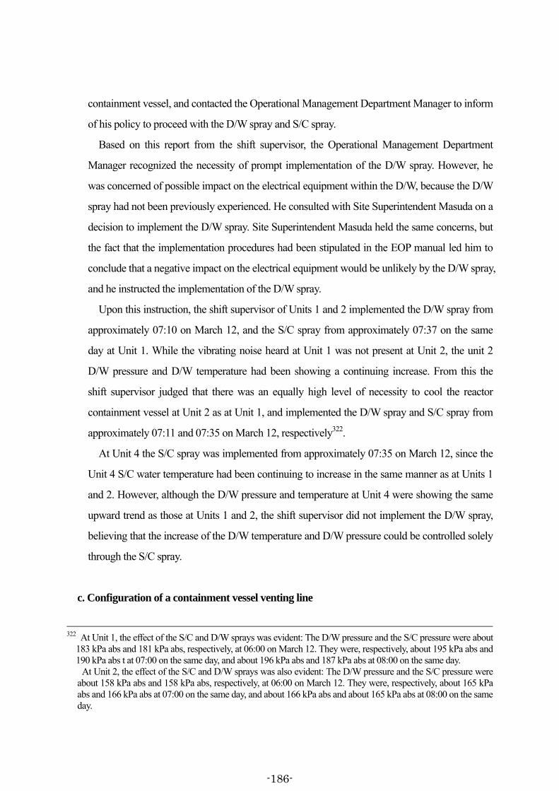
containment vessel, and contacted the Operational Management Department Manager to inform
of his policy to proceed with the D/W spray and S/C spray.
Based on this report from the shift supervisor, the Operational Management Department
Manager recognized the necessity of prompt implementation of the D/W spray. However, he
was concerned of possible impact on the electrical equipment within the D/W, because the D/W
spray had not been previously experienced. He consulted with Site Superintendent Masuda on a
decision to implement the D/W spray. Site Superintendent Masuda held the same concerns, but
the fact that the implementation procedures had been stipulated in the EOP manual led him to
conclude that a negative impact on the electrical equipment would be unlikely by the D/W spray,
and he instructed the implementation of the D/W spray.
Upon this instruction, the shift supervisor of Units 1 and 2 implemented the D/W spray from
approximately 07:10 on March 12, and the S/C spray from approximately 07:37 on the same
day at Unit 1. While the vibrating noise heard at Unit 1 was not present at Unit 2, the unit 2
D/W pressure and D/W temperature had been showing a continuing increase. From this the
shift supervisor judged that there was an equally high level of necessity to cool the reactor
containment vessel at Unit 2 as at Unit 1, and implemented the D/W spray and S/C spray from
approximately 07:11 and 07:35 on March 12, respectively322.
At Unit 4 the S/C spray was implemented from approximately 07:35 on March 12, since the
Unit 4 S/C water temperature had been continuing to increase in the same manner as at Units 1
and 2. However, although the D/W pressure and temperature at Unit 4 were showing the same
upward trend as those at Units 1 and 2, the shift supervisor did not implement the D/W spray,
believing that the increase of the D/W temperature and D/W pressure could be controlled solely
through the S/C spray.
c. Configuration of a containment vessel venting line
322 At Unit 1, the effect of the S/C and D/W sprays was evident: The D/W pressure and the S/C pressure were about
183 kPa abs and 181 kPa abs, respectively, at 06:00 on March 12. They were, respectively, about 195 kPa abs and 190 kPa abs t at 07:00 on the same day, and about 196 kPa abs and 187 kPa abs at 08:00 on the same day.
At Unit 2, the effect of the S/C and D/W sprays was also evident: The D/W pressure and the S/C pressure were about 158 kPa abs and 158 kPa abs, respectively, at 06:00 on March 12. They were, respectively, about 165 kPa abs and 166 kPa abs at 07:00 on the same day, and about 166 kPa abs and about 165 kPa abs at 08:00 on the same day.
-186-

It was clear to Site Superintendent Masuda that, in a situation of the RHR being unable to
activate at Units 1, 2 and 4, the S/C and D/W pressure would continue to rise, and it was to his
awareness that the PCV venting would potentially be needed if the restoration of the RHR was
delayed. The Operational Management Department Manager and the shift supervisors were of
the same opinion.
The TEPCO ERC also had a thought, just as the Dai-ni NPS ERC, that the S/C pressure and
D/W pressure would continue to rise as long as the RHR were unable to activate, and that at
some point the PCV venting might eventually be required for Units 1, 2 and 4.
At the Fukushima Dai-ichi NPS, in the meantime, preparations for implementing the PCV
venting had been underway at Unit 1 from approximately 00:06 on March 12. The process was,
however, being slowed considerably, since the AC and DC power supply had been lost as a
result of the tsunami, the operation to open the valves required for the PCV vent line
configuration had to be performed manually323 and other reasons. The TEPCO ERC concluded
that it would be advisable for the Fukushima Dai-ni NPS to complete the line configuration for
the PCV venting while the incoming power from the Tomioka power line 1L was sustained, and
announced this via the television conference system at approximately 06:18 on the same day.
In response, the Dai-ni NPS ERC therefore began to review the method and procedures for
configuring the PCV vent line. Site Superintendent Masuda thought it necessary to be prepared
for all contingencies that might occur in leading the reactors up to cold shutdown; not only at
Units 1, 2 and 4 where the RHR system had been unable to activate, but also at Unit 3 where
the RHR system had been operational. He decided to undertake the basic procedures planning
by the Dai-ni NPS ERC Operation Team, for configuring an S/C vent line for each of the Units
1 to 4.
In contrast to the Fukushima Dai-ichi NPS, the Dai-ni NPS ERC Operation Team had a
thought that the configuration of the S/C vent lines could be conducted simply from the control
panels of each main control room (MCR)324. The Dai-ni NPS ERC Operation Team planned to
323 Refer to Chapter IV. 3. (5) of the Interim Report for information regarding the implementation of the PCV
venting at Unit 1of the Fukushima Dai-ichi NPS. 324 As will be noted later, recovery work was actually necessary at Unit 1, because the PCV SGTS vent valve was
not able to open from the MCR due to the loss of power source.
-187-
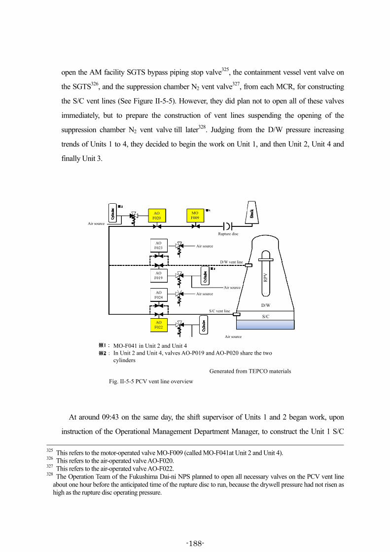
open the AM facility SGTS bypass piping stop valve325, the containment vessel vent valve on
the SGTS326, and the suppression chamber N2 vent valve327, from each MCR, for constructing
the S/C vent lines (See Figure II-5-5). However, they did plan not to open all of these valves
immediately, but to prepare the construction of vent lines suspending the opening of the
suppression chamber N2 vent valve till later328. Judging from the D/W pressure increasing
trends of Units 1 to 4, they decided to begin the work on Unit 1, and then Unit 2, Unit 4 and
finally Unit 3.
Cylinders
Fig. II-5-5 PCV vent line overview
Generated from TEPCO materials
MO-F041 in Unit 2 and Unit 4In Unit 2 and Unit 4, valves AO-P019 and AO-P020 share the two cylinders
D/W
S/C
AOF020
AOF022
MOF009
AOF023
AOF019
AOF024
Rapture disc
D/W vent line
S/C vent line
Air source
Air source
Air source
Air source
Air source
RP
V
At around 09:43 on the same day, the shift supervisor of Units 1 and 2 began work, upon
instruction of the Operational Management Department Manager, to construct the Unit 1 S/C
325 This refers to the motor-operated valve MO-F009 (called MO-F041at Unit 2 and Unit 4). 326 This refers to the air-operated valve AO-F020. 327 This refers to the air-operated valve AO-F022. 328 The Operation Team of the Fukushima Dai-ni NPS planned to open all necessary valves on the PCV vent line
about one hour before the anticipated time of the rupture disc to run, because the drywell pressure had not risen as high as the rupture disc operating pressure.
-188-

vent line from the Units 1 & 2 MCR. A while later, at approximately 10:21, it became known
that the solenoid valve that was to send air and drive the SGTS side vent valve of the
containment vessel could not be opened, due to a loss of power. The shift supervisor halted
work on the S/C vent line configuration at approximately 10:32, and commissioned the Dai-ni
NPS ERC Recovery Team to restore power to this solenoid valve.
The Dai-ni NPS ERC Operation Team decided to begin preparatory work for constructing
the reactor PCV vent lines for Units 2 to 4 in sequential order while the restoration work was
being carried out at Unit 1.
In response to the decision, the shift supervisors completed the preparations for configuration
of the S/C vent lines between the following times on March 12, suspending only the opening
step of the suppression chamber N2 vent valve: approximately from 10:33 by 10:58 at Unit 2;
approximately from 12:08 by 12:13 at Unit 3; and approximately from 11:44 by 11:52 at Unit 4
(See Figure II-5-5).
In the meantime, the Dai-ni NPS ERC Recovery Team restored power to the solenoid valve
that was to send air and drive the SGTS side vent valve of the containment vessel of Unit 1, by
connecting a cable from the AC power (100V) outlet positioned in the Units 1 & 2 MCR to the
solenoid valve electronic circuit on the back side of the control panel. Following this, the shift
team resumed work on constructing the S/C vent line, completing the preparations for
configuration of the S/C vent line at approximately 18:30 of the same day, suspending only the
opening step of the suppression chamber N2 vent valve.
d. RHR operation at Unit 3
The RHR Train B of Unit 3 had been in operation in S/C cooling mode since approximately
15:36 on March 11 immediately after the tsunami.
At approximately 01:23 on March 12, the reactor pressure lowered to about 0.2 MPa gage: a
figure sufficiently low to allow operation of the RHR in SHC mode. The shift team therefore
manually stopped the RHR being operated in S/C cooling mode in order to switch the RHR
operating mode.
However, in the process of switching the RHR operation mode, when the shift team
attempted, on the control panel in the Units 3 & 4 MCR, to open the D/W internal and external
-189-
isolation valves mounted on the RHR piping for SHC mode, these valves could not be opened.
Prior to this, at approximately 19:46 on March 11, a “high D/W pressure” signal had been
actuated at Unit 3. The system is designed to prevent, through an interlock, the opening of the
D/W internal and external isolation valves mounted on the RHR piping for SHC mode when
this signal is actuated. The shift team had assumed that the D/W pressure would not show a
large increase because the RHR Train B had been operating in S/C cooling mode. Consequently
the “high D/W pressure” signal had gone unnoticed to them.
The shift team presumed that an interlock might have worked due to a “high D/W pressure”
signal, based on the fact that the D/W isolation valves could not be opened when switching the
RHR from S/C cooling mode to SHC mode. They checked the alarm typer in the Units 3 & 4
MCR, and it was then that they realized that the “high D/W pressure” signal had been actuated.
The Dai-ni NPS ERC and the shift team thought of a possibility that the reactor coolant
might be leaking inside the D/W, because the “high D/W pressure” signal had been actuated.
They checked the reactor parameters such as the reactor water level, reactor pressure, D/W
pressure, D/W temperature, S/C water temperature, SC pressure and other parameters and
reviewed the possibility of a reactor coolant leak; however, they found no indications of this,
and judged that opening of the D/W internal and external isolation valves would not cause a
problem, by releasing the interlock resulting from the “high D/W pressure” signal.
While the Dai-ni NPS ERC and the shift team were working on this matter, the RHR
operation in the S/C cooling mode was kept suspended. Consequently, the S/C water
temperature was continuing to rise. The shift team judged that it would be better to continue
cooling the S/C in the RHR in S/C cooling mode, if it was not possible to switch the RHR to the
SHC mode for some time. At approximately 02:39 on March 12, the RHR Train B was
reactivated in the S/C cooling mode.
As it was concluded - as mentioned earlier - that there had been no possibility of reactor
coolant leak in the D/W, the shift team decided to re-switch the RHR Train B from the S/C
cooling mode to the SHC mode, and released in the Units 3 & 4 MCR the interlock resulting
from the “high D/W pressure” signal.
The shift team stopped the RHR Train B at approximately 07:59 on the same day, which had
been operating in S/C cooling mode, and they constructed from the Units 3 & 4 MCR the SHC
-190-

mode line, spending approximately between 08:23 and 08:43 of the same day in the opening
and closing operations of the valves. At approximately 09:37 on the same day, the shift team
activated the RHR Train B in SHC mode and began cooling the reactor.
By approximately 12:15 on that day the reactor water temperature fell below 100°C and the
reactor went into cold shutdown.
e. HPCS operation at Unit 4
At Unit 4, the RCIC ceased operation automatically at approximately 00:16 on March 12.
From that time onwards, reactor water injection was being continued by the MUWC, with the
CST as the water source.
The CST water level at Unit 4 had been approximately 8.7 m prior to the earthquake. By
approximately 12:30 on March 12, this dropped to about 4.2 m due to continued use of the CST
as a water source for water injection from the MUWC.
A CST was provided for each unit at the Fukushima Dai-ni NPS, but there were only two
freshwater tanks with which to supply water to these CSTs within the Fukushima Dai-ni NPS
compound. The shift supervisor for Units 3 and 4 had been contacted by the Dai-ni NPS ERC
saying that they wished to prioritize the CSTs of Units 1 and 2 in the use of the water in the
freshwater tanks, since these units had been in most severe plant conditions329.
Taking this situation into consideration, the shift supervisor, intending to reserve as much of
the CST water as possible, decided to halt water injection using the MUWC with the CST as the
water source and, as an alternative method, to use the HPCS for reactor water injection with the
S/C as the water source. He notified the Dai-ni NPS ERC of this plan at around 10:53 on March
12.
For executing water injection into the reactor by the HPCS, the shift team activated the
HPCS at approximately 11:17 on the day and stirred the water inside the S/C, because the S/C
water temperature had risen. At this point the water temperature in the S/C was approximately
329 Regarding Units 1, 2 and 4, the Dai-ni NPS ERC judged the priority level based on the increasing trend of
respective S/C pressure. On March 12, the order of priority was placed on Unit 2, Unit 1 and Unit 4 in this order. Later, when the S/C pressure at Unit 1 showed a sharper increase than at Unit 2 on March 13, the Dai-ni NPS ERC changed the order of priority to Unit 1, Unit 2 and Unit 4.
-191-

103°C in the S/C upper part and approximately 75°C in the S/C lower part. By stirring the water
with the HPCS, the S/C water temperature in all areas became approximately 96°C.
Subsequently, at approximately 12:30 on the same day, the shift team constructed a line for
water injection from the HPCS to the reactor, and at approximately 12:32 on the same day, the
shift operators halted water injection by the MUWC. From then onwards the shift team
intermittently implemented reactor water injection by the HPCS, thus maintaining the reactor
water level.
(7) Response on and after March 13
a. RHR restoration
(a) Delivery of materials and equipment
Upon request of the Dai-ni NPS ERC Recovery Team at approximately 11:24 on March 12,
as stated in (6) a. (c) above, the Kashiwazaki-Kariwa NPS started work to procure the motors
which were required for the recovering the RHRC Pumps (1B and 1D) and EECW Pump (1B)
of Unit 1, by learning their availability at the Mie Work of a contractor. These motors were
transported to the SDF Komaki Airbase, from where the SDF transported them by air from the
Komaki Airbase to the Hirono Town Office via the Fukushima Airport. These motors were
handed over to the Dai-ni NPS ERC Recovery Team and staff of the contractor at the Hirono
Town Office, and arrived at the Fukushima Dai-ni NPS at approximately 06:33 of March 13.
In parallel, the Dai-ni NPS ERC had also requested the Kashiwazaki-Kariwa NPS on March
12 to procure the motors required for recovering RHRC pumps (4B and 4D) of Unit 4. These
motors also arrived at the Fukushima Dai-ni NPS in the morning of March 13. The cables also
arrived at the Fukushima Dai-ni NPS at a similar time, which, on March 11, the Dai-ni NPS
ERC had requested the TEPCO ERC to procure.
(b) Motor replacement and cable laying
By the morning of March 13, when the materials and equipment required for the restoration
of the RHR of each unit arrived at the Fukushima Dai-ni NPS, debris and wreckage had been
mostly removed from the road that ran east-west on the south side of the Unit 1R/B as well as
on the seaward area where the Hx/B of each unit was located.
-192-
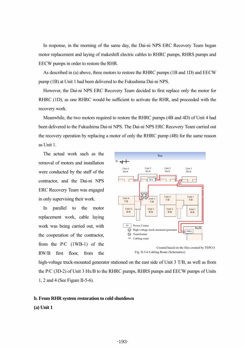
In response, in the morning of the same day, the Dai-ni NPS ERC Recovery Team began
motor replacement and laying of makeshift electric cables to RHRC pumps, RHRS pumps and
EECW pumps in order to restore the RHR.
As described in (a) above, three motors to restore the RHRC pumps (1B and 1D) and EECW
pump (1B) at Unit 1 had been delivered to the Fukushima Dai-ni NPS.
However, the Dai-ni NPS ERC Recovery Team decided to first replace only the motor for
RHRC (1D), as one RHRC would be sufficient to activate the RHR, and proceeded with the
recovery work.
Meanwhile, the two motors required to restore the RHRC pumps (4B and 4D) of Unit 4 had
been delivered to the Fukushima Dai-ni NPS. The Dai-ni NPS ERC Recovery Team carried out
the recovery operation by replacing a motor of only the RHRC pump (4B) for the same reason
as Unit 1.
The actual work such as the
removal of motors and installation
were conducted by the staff of the
contractor, and the Dai-ni NPS
ERC Recovery Team was engaged
in only supervising their work.
In parallel to the motor
replacement work, cable laying
work was being carried out, with
the cooperation of the contractor,
from the P/C (1WB-1) of the
RW/B first floor, from the
high-voltage truck-mounted generator stationed on the east side of Unit 3 T/B, as well as from
the P/C (3D-2) of Unit 3 Hx/B to the RHRC pumps, RHRS pumps and EECW pumps of Units
1, 2 and 4 (See Figure II-5-6).
b. From RHR system restoration to cold shutdown
(a) Unit 1
Created based on the files created by TEPCOFig. II-5-6 Cabling Route (Schematics)
N
Unit 4Hx/b
Unit 3Hx/b
Unit 2Hx/b
Unit 1Hx/b
Unit 4T/B
Unit 4R/B
Unit 3T/B
Unit 3R/B
Unit 2T/B
Unit 1T/B
Unit 1R/B
Unit 2R/B
Power Center
High-voltage truck-mounted generator
Transformer
Cabling route
Sea
G G
Tr
G
Tr
Tr
-193-

At Unit 1, the RHRS pump (1B) and RHRC pump (1D) were activated at approximately
20:17 and 21:03 on March 13, respectively. At this point, the only requirement left for the
restoration of the Unit 1 RHR was the restoration of the EECW pump (1B).
However, since the notification to government authorities was made at approximately 05:47
on March 12 that the S/C water temperature at Unit 1 had exceeded 100°C and that a specific
event (loss of pressure suppression function) pursuant to the provisions of Paragraph 1, Article
15 of the Nuclear Emergency Preparedness Act had occurred, the S/C water temperature
continued to rise despite the S/C spray, and reached approximately 122°C by 21:00 on March
13.
In order to cool the S/C as soon as possible by activating the RHR, the Dai-ni NPS ERC
reviewed whether it would be possible to activate the RHR Train B before the EECW pump
(1B) could be restored. As a result, the Dai-ni NPS ERC judged that it would be possible to
activate the RHR even before the restoration of the EECW pump provided the RHR operation
was limited to the time duration up until the friction caused temperature rise of the RHR pump
motor, because the EECW pump was a system to cool the bearings of the RHR pump motor.
Also by this point, the EECW pump (1B) restoration was in sight. Therefore, on the
condition that the RHR pump could be shut down immediately if an alarm was actuated while
monitoring the RHR pump motor temperature, the RHR Train B was activated and operation
commenced in the S/C cooling mode at approximately 01:24 of March 14330 (see Attachment
II-5-13).
The Unit 1 RHR Train B was continuing to operate in the S/C cooling mode. The shift team
decided, at 10:05 on the same day, to configure a line which would allow the water to be
injected into the reactor simultaneously while continuing the S/C cooling through the RHR.
The new method consisted of a partial change to the existing line configuration of S/C
cooling mode, whereby the S/C water is cooled in the RHR heat exchanger and returned to the
S/C. In the new method, the S/C water which was cooled using the RHR heat exchanger was
returned to the S/C, and at the same time part of the water was also injected into the reactor via
the RHR low pressure water injection mode piping, and the water could be circulated back to
the S/C through the SRV which remained open, once the reactor was filled with water (see 330 The EECW pump (1B) was restored at approximately 01:44 on March 14.
-194-

Attachment II-5-13).
The shift team continued this operation method as it allowed to cool the S/C and to inject
water to the reactor simultaneously. Upon confirming later that the S/C water temperature had
fallen below 100°C, the shift team reported this to the Dai-ni NPS ERC.
Upon receiving this information, Site Superintendent Masuda judged, at approximately 10:15
of the same day, that the situation was no longer under a specific event (loss of pressure
suppression function) pursuant to the provisions of Paragraph 1, Article 15 of the Nuclear
Emergency Preparedness Act, and reported this to the relevant authorities at approximately
10:35 on the same day.
At Unit 1, water injection into the reactor and the S/C cooling were continued in the same
manner, and the reactor water temperature dropped to below 100°C at approximately 13:40 on
the same day. Confirming later that the reactor water temperature was on a stable downward
shift and that the temperature would not exceed 100°C again, the Dai-ni NPS ERC judged at
approximately 17:00 of the same day that Unit 1 had reached cold shutdown.
(b) Unit 2
At Unit 2, the external power was restored by laying makeshift cables from the P/C (1WB-1)
in the RW/B first floor and the P/C (3D-2) in the Unit 3 Hx/B to the RHRC pumps, RHRS
pumps and EECW pump, as described in a. (b) above. The EECW pump (2B) was activated at
approximately 03:20 on March 14, the RHRS pump (2B) was activated at approximately 03:51
of the same day, and the RHRC pump (2B) was activated at approximately 05:52 of the same
day, respectively.
The shift team then activated the RHR Train B and began operation in the S/C cooling mode
at approximately 07:13 of the same day (see Attachment II-5-13).
Later, at approximately 10:48 of the same day, the shift team switched to the same operation
method used in Unit 1, where the RHR line was configured so that water could be injected
simultaneously to the reactor while the S/C cooling was maintained (see Attachment II-5-13).
Since the S/C water temperature dropped below 100°C at approximately 14:10, Site
Superintendent Masuda judged at approximately 15:52 of the same day that the situation was
no longer under a specific event (loss of pressure suppression function) pursuant to provisions
-195-

of Paragraph 1, Article 15 of the Nuclear Emergency Preparedness Act, and reported to the
government authorities of this at approximately 16:15 of the same day.
At Unit 2, they continued to utilize the same method to inject water into the reactor and cool
the S/C, and the reactor water temperature dropped to 100°C or below at approximately 14:20
of the same day. Upon confirming later that the reactor water temperature was on a stable
downward shift and that the temperature would not exceed 100°C again, the Dai-ni NPS ERC
judged at approximately 18:00 of the same day that Unit 2 had reached cold shutdown.
(c) Unit 4
At Unit 4, the EECW pump (4B) was activated at approximately 11:00 on March 14, the
RHRS pump (4B) was activated at approximately 13:07 of the same day, and the RHRC pump
(4B) was activated at approximately 14:56 of the same day, respectively.
The shift team then activated the RHR Train B and began operation in the S/C cooling mode
at approximately 15:42 of the same day (see Attachment II-5-13).
Later, at approximately 21:43 of the same day, after receiving advice from the Dai-ni NPS
ERC, the shift team switched to the same operation method used in Unit 1, by configuring the
RHR line so that water could be injected simultaneously to the reactor while cooling the S/C
was maintained (see Attachment II-5-13).
Since the S/C water temperature dropped to below 100°C later, Site Superintendent Masuda
judged at approximately 07:15 on March 15 that the situation was no longer under a specific
event (loss of pressure suppression function) as defined in Paragraph 1, Article 15 of the
Nuclear Emergency Preparedness Act and reported to government authorities accordingly at
approximately 07:35 on the same day.
At Unit 4, the reactor water temperature was below 100°C by approximately 03:50 on the
same day and was on a stable downward shift, the Dai-ni NPS ERC judged at approximately
07:15 of the same day that Unit 4 had reached cold shutdown.
(8) Responses to the accident at the Fukushima Dai-ichi NPS and the Fukushima Dai-ni NPS:
The responses and comparison
From (1) to (7) above, the responses to the accident at the Fukushima Dai-ni NPS have been
-196-
summarized for the time span from the occurrence of earthquake to the cold shutdown of each
unit.
The damage at the Fukushima Dai-ni NPS following the Tohoku District - off the Pacific
Ocean Earthquake and ensuing massive tsunami waves differs significantly from that of the
Fukushima Dai-ichi NPS, in that the external power was maintained after the earthquake, and
the function of monitoring equipment for grasping the conditions of the nuclear reactors was
functioning even after the arrival of tsunami.
However, as the goal to bring nuclear reactors to cold shut-down safely and quickly was
common at these two stations, it is important to compare the responses to the accident taken by
both the Fukushima Dai-ichi NPS and the Fukushima Dai-ni NPS. The following two points
will be reviewed from this perspective, referring to Chapter IV of the Interim Report as well.
a. Switching-over from high pressure water injection to low pressure water injection
(Comparison with the responses to the accident at Unit 3 of the Fukushima Dai-ichi NPS)
(a) Responses to the accident at Unit 3 of the Fukushima Dai-ichi NPS
(i) At Unit 3 of the Fukushima Dai-ichi NPS, the injection of water into the reactor was
continuing through the HPCI from approximately 12:35 on March 12. The operation of the
HPCI caused a notable drop in the reactor pressure of Unit 3, and from approximately 19:00 of
the same day, the reactor pressure of Unit 3 was showing 0.8 MPa gage to 1.0 MPa gage on the
reactor pressure indicator.
The HPCI was a water injection system which had been originally designed for injecting
large volumes of water into the reactor in a short space of time when the reactor pressure was at
a high level of between approximately 1.03 MPa gage to 7.75 MPa gage.
However, in actuality, the shift team had been running the HPCI continuously for a long
period at an RPM lower than the operable range specified in the procedures331 while adjusting
the flow rate, when the reactor pressure was below 1.0 MPa gage. Furthermore, since
approximately 20:36 of the same day, the reactor water level measurement devices became
inoperable, and the HPCI discharge pressure was declining, and began competing with the
331 The Unit 3 EOP of the Fukushima Dai-ich NPS prohibits to lower the turbine revolution below 2,060 rpm for
continuous HPCI operation.
-197-
reactor pressure. The shift team became concerned about the damage to the HPCI, as the
absence of the reactor water level information made it unclear whether a sufficient amount of
water was being injected through the HPCI in an unusual operational mode different from the
standard operational mode. Therefore, intending to switch over to reactor water injection by a
diesel-driven Fire Pump (D/DFP), they manually shut down the HPCI at approximately 02:42
on March 13.
(ii) On the other hand, in order to configure the line for water injection by D/DFP, the shift
members entered the R/B of Unit 3 before manually shutting down the HPCI. However, the
means of communication had not been established between the shift members who headed to
the destination, and the Units 3 & 4 MCR. The order in which the D/DFP water injection line
configuration at the site and the HPCI manual shutdown operation in the Units 3 & 4 MCR is
unclear, but the shift team in the Units 3 & 4 MCR, at least, had not confirmed the completion
of D/DFP water injection line configuration before manually shutting down the HPCI332.
(iii) Then, the shift team undertook the opening procedure of the SRV through remote
operation on the control panels in the Units 3 & 4 MCR on March 13 at around 02:45 and 02:55
for depressurization by the SRV. However, the SRV did not open with this operation, and the
shift team failed to depressurize the reactor by manually opening the SRV.
Furthermore, as the situation was prolonged where water injection through D/DFP was not
possible, the shift team attempted to restart the HPCI. But, it could not be restarted.
(iv) The Emergency Response Center at the Fukushima Dai-ichi NPS (hereinafter, “Dai-ichi
NPS ERC”) and the shift team continued to struggle to depressurize the reactor through the SRV,
and as a consequence, the condition of no water injection at all to Unit 3 had to remain over the
period from the time the shift team had manually shut down the HPCI at approximately 02:42
of March 13, to the time when water injection to the reactor using fire engines began at 332 The operators' logbook records in the column at 03:05 of March 13 as “D/DFP pump injected to reactor,
MO-10-27B 15% open, sound of flow seemed to have been heard at 7%,” indicating that the D/DFP reactor injection line configuration had been reported from the shift members, who had entered inside the R/B before the HPCI was manually shutdown. According to this logbook, the confirmation by the MCR of the completion of D/DFP reactor water injection line configuration is considered to be after approximately 03:05 of the same day.
On the other hand, a shift member of the Fukushima Dai-ichi NPS Unit 3 stated to this Committee in the hearing that at the point when the HPCI system had been manually shut down, he had not confirmed whether the D/DFP reactor water injection line had been configured. Therefore, it is clear that the shift who had manually shut down the HPCI system did not know at that time whether the D/DFP reactor water injection line configuration had been completed.
-198-
approximately 09:25333 of the same day.
(b) Responses to the accident at Fukushima Dai-ni NPS
(i) At Unit 1, the shift team was continuing to inject water into the reactor using the RCIC
from around 15:36 of March 11. Later, in order to switch over to the MUWC from the RCIC for
water injection, the shift supervisor decided, as noted in (5) c. (d) above, to configure a water
injection line from the MUWC while the RCIC was still operational and to confirm that it
would actually be possible to inject water into the reactor using the MUWC. This was in order
to avoid a situation where the MUWC failed to work due to some kind of contingency after the
switch had been made from the RCIC to MUWC methods of injecting water into the reactor
and the RCIC had shut down. When the water injection line that ran from the MUWC to the
reactor via the RHR was configured, the shift supervisor confirmed water injection by MUWC
three times from approximately 23:58 of the same day.
Then, the shift team carried out the rapid depressurization operation at approximately 03:48
on March 12, when the reactor pressure and the S/C water temperature met the operation
criteria for rapid depressurization as specified in the EOP, after confirming that the MUWC
water injection into the reactor had begun. At approximately 04:58 of the same day, the shift
team manually closed the RCIC steam isolation valve when the reactor pressure dropped,
considering that the RCIC turbine RPM would fall below the lower limit of the operation range.
(ii) At Unit 2, the shift team was continuing water injection to the nuclear reactor using the
RCIC since approximately 15:43 of March 11. Similarly to Unit 1, the shift team configured the
water injection line from the MUWC via the RHR in order to confirm, while the RCIC was still
operating, that water injection using the MUWC was possible and confirmed twice the water
injection through the MUWC since approximately 21:26 of the same day. Later, when the
reactor pressure dropped and approached the pressure to automatically isolate the RCIC, the
shift team commenced water injection through the MUWC at approximately 04:50 on March
12. At approximately 04:53 of the same day, the RCIC automatically shut down as the reactor
333 On the other hand, the plant parameters recorded at Unit 3 of the Fukushima Dai-ichi NPS indicate that the
reactor pressure was reduced to as low as 0.460 MPa gage by approximately 09:10 of March 13. As it is conceivable that preparation for the alternative water injection using fire engines was ready by that time, it is possible that the alternative water injection started at this point (see Attachment II-1-1 Chapter 4. 1. (3)).
-199-

pressure had dropped.
(iii) At Unit 3, the shift team was continuing injecting water into the reactor using the RCIC
since approximately 16:06 of March 11. Subsequently, as detailed in (5) d. (d) above, the shift
team configured the water injection line from the MUWC via the RHR, in order to confirm,
while the RCIC was still in operation, that water injection using the MUWC was viable. The
MUWC water injection into the reactor was confirmed at approximately 22:53 on the same day.
The shift team commenced the MUWC water injection at approximately 23:15 of the same day
after manually shutting down the RCIC at approximately 23:11 when the reactor pressure had
continued to drop and the RCIC turbine RPM had approached the lower limit of the operation
range.
(iv) At Unit 4, the shift team was continuing injecting water into the reactor using the RCIC
since approximately 15:54 of March 11. Similarly to Unit 3, the shift team configured a water
injection line from the MUWC via the RHR in order to confirm, while the RCIC was still in
operation, that the water injection using the MUWC was possible and confirmed the MUWC
water injection at approximately 23:33 of the same day. Later, the reactor pressure continued to
drop, and the RCIC shut down automatically at approximately 00:16 on May 12. The shift team
then commenced the MUWC water injection at around that time.
(c) The issues to note
(i) Generally, the decay heat immediately after shutting down an operating nuclear reactor is
extremely large. If water injection to the reactor were interrupted, the water level of the reactor
would drop, uncovering the fuel, and the core would likely be damaged. In other words, for
avoiding core damage and cooling stably the reactor, it is necessary to continue injecting water
into the reactor without interruption so as not to uncover the fuel.
This is the same even when switching the means of injecting water into the reactor; the
switch-over must be carried out quickly and with utmost caution to make sure that the water
injection is not interrupted by unexpected events.
Accordingly, when switching from high pressure water injection to low pressure water
injection, it is necessary to depressurize the reactor via the SRV while the high pressure water
injection is functional, rapid depressurization being performed as required, and to transfer
-200-

quickly to low pressure water injection, as is clear from the operating manual created by
TEPCO334 as well as from the responses to the accident at the Fukushima Dai-ni NPS. For
perfect implementation of such maneuvering steps, thorough measures must be taken in
advance to ensure that any procedures necessary for enabling low pressure water injection be
prepared, subject to the specific plant conditions, while high pressure injection remains
functional.
(ii) At the Fukushima Dai-ni NPS, injection of water into the reactor was being carried out at
each unit by the RCIC following the tsunami, and the alternative method to succeed for
injecting water into the reactor was the MUWC via the RHR.
In order to carry out water injection using the MUWC, the configuration of a water injection
line as well as reactor depressurization using the SRV were required.
Given these conditions, in order to inject water to the reactor without interruption at the
Fukushima Dai-ni NPS, it was necessary to establish an alternative water injection line well in
advance while the RCIC was still in operation, and, by confirming that water injection could
definitely be carried out as long as the reactor was depressurized, to switch over to the
alternative water injection method, while depressurizing the reactor using the SRV as necessary.
When reviewing the responses to the accident at Units 1 and 2 of the Fukushima Dai-ni NPS,
the following sequence of actions have been taken. In transferring the water injection method
from the RCIC to the MUWC via RHR, the MUWC water injection line was configured and
checks were carried out, by depressurizing the reactor using the SRV, whether the MUWC
water injection was actually possible or not, while water injection through the RCIC was
ongoing at each unit335. Furthermore, at Units 1 and 2 of the Fukushima Dai-ni NPS, when
334 The Unit 3 EOP of the Fukushima Dai-ich NPS requires the operator, in the item “Cooling by depressurization,”
to use the SRV, if the main condenser is not available. The EOP requires at the same time to maintain the reactor water level between TAF and L-8 by water injection using the RCIC, HPCI or other water injection means.
The EOP specifies the reactor pressure to initiate rapid depressurization depending on the S/C water temperature. When the reactor pressure exceeds the pre-specified pressure, the EOP requires the operator to manually open the SRV for rapid depressurization. Depending on the conditions of the reactor and S/C, the EOP requires initiating the rapid depressurization only after establishing a low pressure injection means or an alternative water injection means.
335 At the Fukushima Dai-ni NPS, the reactor depressurization by the SRV necessary for switching to the MUWC water injection, and the configuration work of the water injection line via the MUWC were being done in parallel, while the RCIC was injecting water into the reactor after the arrival of tsunami. For most careful preparation, however, the depressurization process should have been initiated after the alternative water injection means viability had been confirmed. As a matter of fact, the Kashiwazaki-Kariwa NPS specifies to start depressurizing
-201-
switching the water injection method from the RCIC over to the MUWC, MUWC water
injection had commenced before the RCIC was shut down, and therefore water injection was
never interrupted336.
On the other hand, in the responses to the accident taken at the Fukushima Dai-ni NPS Units
3 and 4, MUWC water injection commenced after the RCIC had shut down, when changing the
water injection method, and therefore there was a time when injection of water into the reactor
was interrupted, albeit for a short period. To note is, similar to Units 1 and 2, Fukushima Dai-ni
NPS Units 3 and 4 also underwent, while RCIC water injection was continuing, MUWC water
injection line configuration and, upon reactor depressurization through the SRV, the viability of
the MUWC water injection had been confirmed several tens of minutes prior to the actual
commencement.
(iii) For comparison, measures required for uninterrupted injection of water into the reactor at
Unit 3 of the Fukushima Dai-ichi NPS will be examined below.
i. At Unit 3 of the Fukushima Dai-ichi NPS, as described in (a) above, the HPCI was
activated automatically at approximately 12:35 on March 12, and being in operation while
controlling its flow rate. However, different from the RCIC of the Fukushima Dai-ni NPS
which was running normally, the HPCI at the Fukushima Dai-ichi was being operated at an
RPM below the allowable operating range specified in the procedures, from approximately
19:00 of the same day, in a condition when the reactor pressure was below 1.0 MPa gage.
In the meantime, in the evening of the same day, the batteries for the equipment needed for
plant control depleted successively, and the possibility existed that the HPCI, which had been
running for a long period, too, could shut down due to depletion of power. Additionally, the
possibility of an unexpected event, such as a shutdown for an unknown reason, could not be
denied. As a matter of fact, the RCIC at Unit 3 of the same Fukushima Dai-ichi NPS had shut
down for an unknown reason at around 11:36 of the same day.
the reactor by the SRV after confirming the completion of the alternative water injection lines in its “Guidelines for tsunami accident management.” The Kashiwazaki-Kariwa NPS formulated the guidelines, with reference to the Fukushima accident, in which the loss of seawater system functions and all AC power were assumed to occur as a result of a tsunami.
336 On this point, a shift operator of the Fukushima Dai-ni NPS stated to this Committee in the hearing that the most important point in running the nuclear reactor was to maintain water injection to the reactor, and that it was quite natural for the shift to always have a backup method being prepared for injecting water into the reactor.
-202-
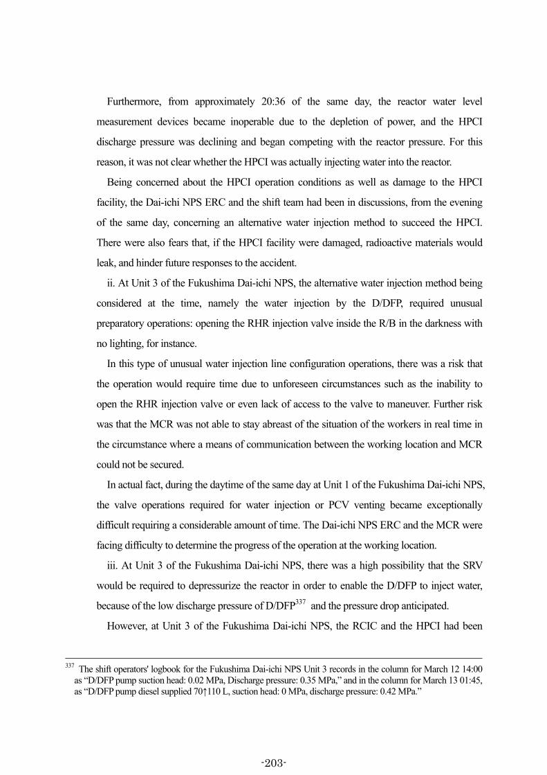
Furthermore, from approximately 20:36 of the same day, the reactor water level
measurement devices became inoperable due to the depletion of power, and the HPCI
discharge pressure was declining and began competing with the reactor pressure. For this
reason, it was not clear whether the HPCI was actually injecting water into the reactor.
Being concerned about the HPCI operation conditions as well as damage to the HPCI
facility, the Dai-ichi NPS ERC and the shift team had been in discussions, from the evening
of the same day, concerning an alternative water injection method to succeed the HPCI.
There were also fears that, if the HPCI facility were damaged, radioactive materials would
leak, and hinder future responses to the accident.
ii. At Unit 3 of the Fukushima Dai-ichi NPS, the alternative water injection method being
considered at the time, namely the water injection by the D/DFP, required unusual
preparatory operations: opening the RHR injection valve inside the R/B in the darkness with
no lighting, for instance.
In this type of unusual water injection line configuration operations, there was a risk that
the operation would require time due to unforeseen circumstances such as the inability to
open the RHR injection valve or even lack of access to the valve to maneuver. Further risk
was that the MCR was not able to stay abreast of the situation of the workers in real time in
the circumstance where a means of communication between the working location and MCR
could not be secured.
In actual fact, during the daytime of the same day at Unit 1 of the Fukushima Dai-ichi NPS,
the valve operations required for water injection or PCV venting became exceptionally
difficult requiring a considerable amount of time. The Dai-ichi NPS ERC and the MCR were
facing difficulty to determine the progress of the operation at the working location.
iii. At Unit 3 of the Fukushima Dai-ichi NPS, there was a high possibility that the SRV
would be required to depressurize the reactor in order to enable the D/DFP to inject water,
because of the low discharge pressure of D/DFP337 and the pressure drop anticipated.
However, at Unit 3 of the Fukushima Dai-ichi NPS, the RCIC and the HPCI had been
337 The shift operators' logbook for the Fukushima Dai-ichi NPS Unit 3 records in the column for March 12 14:00
as “D/DFP pump suction head: 0.02 MPa, Discharge pressure: 0.35 MPa,” and in the column for March 13 01:45, as “D/DFP pump diesel supplied 70↑110 L, suction head: 0 MPa, discharge pressure: 0.42 MPa.”
-203-

running continuously over a long period since the tsunami had reached the site albeit with
various reduction of loads, and the risks were being considered that the power for opening the
SRV could be depleted338 and that the nitrogen gas pressure for driving to open the SRV
could become insufficient.
iv. Given these conditions, in order to continue water injection into the reactor without
interruption, the water injection means should have been switched to an alternative injection
line through the SRV as necessary, as soon as concerns were felt regarding the continuous
operation of the HPCI, by configuring the alternative water injection line and by confirming
in advance that water injection could definitely be carried out at any time upon the reactor
depressurization.
(iv) However, the measures required for injecting water into the reactor without interruption
as described in (iii) above were not taken at Unit 3 of the Fukushima Dai-ichi NPS.
i. By the evening of March 12, the Dai-ichi NPS ERC and the shift team had raised
concerns over the water injection functionality of the HPCI as well as potential damage to the
system. Nevertheless, at this point they did not attempt to prepare a method of water injection
alternative to the HPCI, namely the configuration of water injection line through the D/DFP.
In contrast, at the Fukushima Dai-ni NPS, the RCIC was functioning normally and there
were no concerns such as those with regards to the HPCI held at Unit 3 of the Fukushima
Dai-ichi NPS. Despite this, however, a line was configured for MUWC water injection as an
338 Since approximately 20:36 on March 12, the reactor water level indicators were inoperable due to power loss.
Causal correlation between this point and the possibility of the SRV opening procedure is examined below. The situation where the measurement on the reactor water level indicators was not possible at Unit 3 was
continuing when the shift team manually stopped the HPCI and attempted to open the SRV at 02:45 and 02:55 of March 13, and it is clear that the shift team was attempting to depressurize the reactor through the SRV while the reactor water level indicators were inoperable. In addition, in responding to the accident, the shift team used the oral information of the reactor pressure as the index to maneuver the SRV for reactor depressurization. The reactor water level was not used as the basis for the judgments. Furthermore, the Unit 3 EOP of the Fukushima Dai-ichi NPS specifies, in its item “Reactor water level unknown,” that the operation procedure to ensure water injection, when the reactor water level became unknown, is to “shift to a contingency mode ‘rapid depressurization’ by activating the low pressure water injection system, even single” and, further, “if the low pressure water injection system is inoperable, activate an alternative water injection line and if it works, shit to the contingency mode ‘rapid depressurization.’” This means that, when the reactor water level is unknown, at least one low pressure water injection system or an alternative water injection line must be established and then the rapid depressurization procedure should be taken in order to secure the water injection means to the reactor.
Therefore, it cannot be justifiable that the reactor depressurization procedure by the SRV was delayed or the switching to the water injection line using the D/DFP was delayed because the reactor water levels had been unable to measure.
-204-

alternative water injection method, while the RCIC was running.
Furthermore, water injection line configuration work through the D/DFP could be
accomplished only by the shift team of Unit 3. Even if the Dai-ichi NPS ERC was being
pressed at that night in responding to the accidents at Units 1 and 2, it cannot be a legitimate
reason for failing to configure the D/DFP water injection line.
ii. When manually shutting down the HPCI, the shift team of Unit 3 of the Fukushima
Dai-ichi NPS did so without first confirming whether the configuration of the D/DFP water
injection line had been complete or not.
Reflecting on the situation at Unit 3 of the Fukushima Dai-ichi NPS as described in (iii) ii.
and iii. above, it is clear that: in responding to such exceptionally serious accident, the
configuration of the D/DFP water injection line should never have been assumed complete,
just because the configuration work of the D/DFP water injection line had had been
underway since 02:00 on March 13, without taking into consideration the possibility of
unforeseen circumstances.
iii. In Unit 3 of the Fukushima Dai-ichi NPS, the reactor depressurization using the SRV
was attempted after the HPCI had shut down, with no prior confirmation of whether or not
the D/DFP water injection line configuration had been complete.
Even if the SRV status indicator lamp on the control panels lit up while the HPCI was
active, as is clear from (iii) iii. above, it was not possible just from this indication to
determine whether there was sufficient nitrogen pressure for driving the SRV, nor was it
possible to deny the possibility that the SRV might not open due to unexpected events.
Therefore, it is not guaranteed that the SRV can always be opened simply because the status
indicator lamp on the control panels is lit up. In responding to this kind of serious accident, it
is conceivable that the possibility of the SRV not opening could have been predicted, and the
SRV should have been attempted to open while the HPCI was still active. If the valve failed
to open, the cause should have been found and repairs made while the HPCI remained active,
and they should have depressurized the reactor through the SRV with a sufficient time margin
to allow all of the above to be achieved.
(v) As stated in (iii) iv. above, at Unit 3 of the Fukushima Dai-ichi NPS, it was necessary, in
order to continue water injection into the reactor without interruption, to depressurize the reactor
-205-

using the SRV at the point when concerns were first raised regarding the continuous operation
of the HPCI, by configuring the D/DFP water injection line with leeway, while the HPCI was
still in operation, and by confirming that water injection could definitely be carried out anytime
upon the reactor depressurization.
However, the commencement of water injection line configuration using D/DFP was delayed,
and there was a possibility that this line had not been configured yet. Nevertheless, as described
in (a) above, the Dai-ichi NPS ERC and the shift team manually shut down the HPCI without
appropriate evaluation of the risks, and undertook the opening operation of the SRV afterward
for the first time. Therefore, it cannot be understood that the necessary measures for injecting
water into the reactor without interruption had been taken.
b. S/C water temperature and S/C pressure monitoring, and subsequent responses
(Comparison with the response to the accident at Unit 2 of the Fukushima Dai-ichi NPS)
(a) The response to the accident at Unit 2 of the Fukushima Dai-ichi NPS
(i) At Unit 2 of the Fukushima Dai-ichi NPS, the RCIC was running active after the tsunami
hit, but, because the DC power had been lost, it was in a condition not able to control the RCIC
and it was unpredictable when the RCIC might shut down.
At approximately 04:00 of March 12, the shift team noticed the decline of the water level in
the CST which had been the water source for the RCIC. Between the period of approximately
04:20 and 05:00 of the same day, they switched the water source from the CST to the S/C in
order to control the rise in the S/C water level. With this, at Unit 2 of the Fukushima Dai-ichi
NPS, the RCIC was run continuously with the S/C as its water source despite the situation that
the RHR was not functioning. This meant the temperature of water/steam that circulated
between the pressure vessel and the S/C was to increase over time, leading to an increase in the
S/C water temperature and the S/C pressure.
(ii) However, at Unit 2 of the Fukushima Dai-ichi NPS, the S/C water temperature and S/C
pressure were not measured at all from the time when the tsunami had reached the site until
approximately 04:30 of March 14. Measurement of the S/C pressure commenced at
approximately 04:30 on the same day, at which point it indicated 0.467 MPa abs on the S/C
pressure gauge, continuing subsequently the rising trend, and by approximately 12:30 of the
-206-
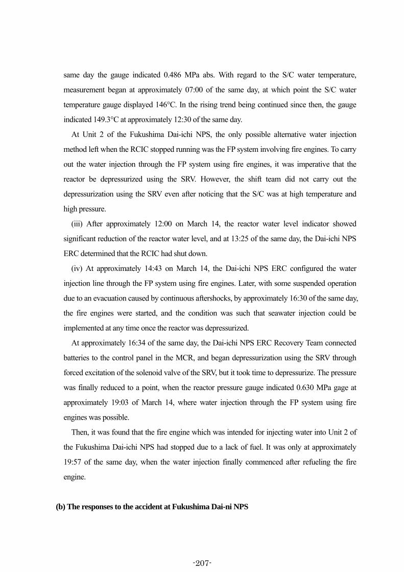
same day the gauge indicated 0.486 MPa abs. With regard to the S/C water temperature,
measurement began at approximately 07:00 of the same day, at which point the S/C water
temperature gauge displayed 146°C. In the rising trend being continued since then, the gauge
indicated 149.3°C at approximately 12:30 of the same day.
At Unit 2 of the Fukushima Dai-ichi NPS, the only possible alternative water injection
method left when the RCIC stopped running was the FP system involving fire engines. To carry
out the water injection through the FP system using fire engines, it was imperative that the
reactor be depressurized using the SRV. However, the shift team did not carry out the
depressurization using the SRV even after noticing that the S/C was at high temperature and
high pressure.
(iii) After approximately 12:00 on March 14, the reactor water level indicator showed
significant reduction of the reactor water level, and at 13:25 of the same day, the Dai-ichi NPS
ERC determined that the RCIC had shut down.
(iv) At approximately 14:43 on March 14, the Dai-ichi NPS ERC configured the water
injection line through the FP system using fire engines. Later, with some suspended operation
due to an evacuation caused by continuous aftershocks, by approximately 16:30 of the same day,
the fire engines were started, and the condition was such that seawater injection could be
implemented at any time once the reactor was depressurized.
At approximately 16:34 of the same day, the Dai-ichi NPS ERC Recovery Team connected
batteries to the control panel in the MCR, and began depressurization using the SRV through
forced excitation of the solenoid valve of the SRV, but it took time to depressurize. The pressure
was finally reduced to a point, when the reactor pressure gauge indicated 0.630 MPa gage at
approximately 19:03 of March 14, where water injection through the FP system using fire
engines was possible.
Then, it was found that the fire engine which was intended for injecting water into Unit 2 of
the Fukushima Dai-ichi NPS had stopped due to a lack of fuel. It was only at approximately
19:57 of the same day, when the water injection finally commenced after refueling the fire
engine.
(b) The responses to the accident at Fukushima Dai-ni NPS
-207-

(i) At the Fukushima Dai-ni NPS, with the exception of the RHR Train B of Unit 3, all other
RHRs were unable to activate due to the effect of tsunami. The shift supervisors were
depressurizing the reactor through the SRV from the time when the RCIC were still running,
and continued monitoring the conditions of S/C by means of the S/C temperature indicators and
S/C pressure indicators, with an anticipation that the steam which was both high in temperature
and pressure entering the S/C would cause a rise in the S/C water temperature and S/C pressure
in a situation where the RHR could not cool the S/C.
(ii) In the meantime, when the “high S/C water level” signal was actuated at all units from
Units 1 to 4, the shift supervisors switched the water source of the RCIC of each unit from the
CST to the S/C. Under these conditions the shift supervisors were intensifying the monitoring
of the S/C conditions, anticipating the following: In a situation where all of the RHR but Unit 3
Train B could not be activated due to the effects of the tsunami, if the RCIC operation was
continued with the S/C as the water source, the temperature of the water/steam that circulates
between the pressure vessel and the S/C would eventually increase, causing the rise in the S/C
water temperature and the S/C pressure accordingly, and the pressure suppression function of
the S/C would be compromised, preventing reactor depressurization using the SRV, and
preventing the switch over to an alternative water injection method upon shutdown of the
RCIC.
(iii) As a matter of fact, at the Fukushima Dai-ni NPS, as described in (5) c. (b) and (c) as
well as in (5) d. (b) and (c) above, the shift teams had been continually monitoring the S/C
water temperature and the S/C pressure as instructed by the shift supervisors. In parallel, the
plant parameters such as these were communicated successively to the Operation Team of the
Dai-ni NPS ERC via information liaison personnel who had been dispatched to each of the
MCRs, and shared with the Dai-ni NPS ERC.
At Unit 1, as a result of continual monitoring of the S/C water temperature and S/C pressure,
the shift team recognized at approximately 03:48 on March 12 that the S/C water temperature
had reached approximately 96°C when the reactor pressure was approximately 1 MPa gage.
Consequently, the shift team was able to determine that the conditions had been reached for the
rapid depressurization operation as specified in the EOP. In accordance with the EOP provisions,
the shift team prepared for the MUWC based water injection and once this was complete,
-208-
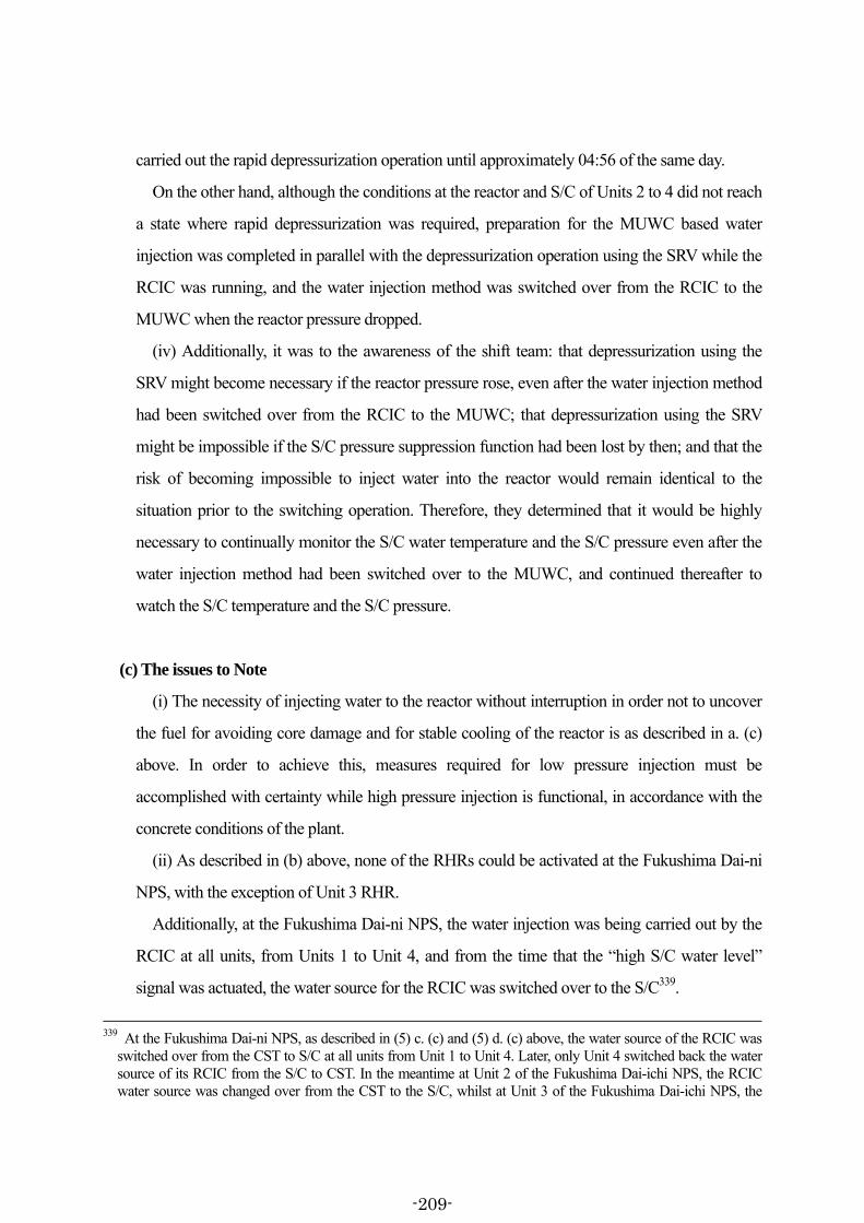
carried out the rapid depressurization operation until approximately 04:56 of the same day.
On the other hand, although the conditions at the reactor and S/C of Units 2 to 4 did not reach
a state where rapid depressurization was required, preparation for the MUWC based water
injection was completed in parallel with the depressurization operation using the SRV while the
RCIC was running, and the water injection method was switched over from the RCIC to the
MUWC when the reactor pressure dropped.
(iv) Additionally, it was to the awareness of the shift team: that depressurization using the
SRV might become necessary if the reactor pressure rose, even after the water injection method
had been switched over from the RCIC to the MUWC; that depressurization using the SRV
might be impossible if the S/C pressure suppression function had been lost by then; and that the
risk of becoming impossible to inject water into the reactor would remain identical to the
situation prior to the switching operation. Therefore, they determined that it would be highly
necessary to continually monitor the S/C water temperature and the S/C pressure even after the
water injection method had been switched over to the MUWC, and continued thereafter to
watch the S/C temperature and the S/C pressure.
(c) The issues to Note
(i) The necessity of injecting water to the reactor without interruption in order not to uncover
the fuel for avoiding core damage and for stable cooling of the reactor is as described in a. (c)
above. In order to achieve this, measures required for low pressure injection must be
accomplished with certainty while high pressure injection is functional, in accordance with the
concrete conditions of the plant.
(ii) As described in (b) above, none of the RHRs could be activated at the Fukushima Dai-ni
NPS, with the exception of Unit 3 RHR.
Additionally, at the Fukushima Dai-ni NPS, the water injection was being carried out by the
RCIC at all units, from Units 1 to Unit 4, and from the time that the “high S/C water level”
signal was actuated, the water source for the RCIC was switched over to the S/C339.
339 At the Fukushima Dai-ni NPS, as described in (5) c. (c) and (5) d. (c) above, the water source of the RCIC was
switched over from the CST to S/C at all units from Unit 1 to Unit 4. Later, only Unit 4 switched back the water source of its RCIC from the S/C to CST. In the meantime at Unit 2 of the Fukushima Dai-ichi NPS, the RCIC water source was changed over from the CST to the S/C, whilst at Unit 3 of the Fukushima Dai-ichi NPS, the
-209-

Furthermore, at the Fukushima Dai-ni NPS, reactor depressurization was being carried out
repetitively using the SRV, because they had planned water injection into the reactor using the
MUWC via RHR as an alternative to the RCIC.
Under such circumstances, the S/C temperature and the S/C pressure would rise, and the
pressure suppression capability of the S/C might be compromised. This would mean that
depressurization would not be sufficient even if the SRV was opened, and there was a risk that
water injection using the MUWC would become impossible. For this reason, it was necessary
to change over to the water injection using the MUWC before the pressure suppression function
of the S/C was lost, by depressurizing the reactor using the SRV.
Accordingly, each shift supervisor continually monitored the S/C water temperature
indicators and S/C pressure indicators in order to grasp the conditions in the S/C, depressurized
the reactor in stages using the SRV, and switched the water injection method from the RCIC to
the MUWC after having confirmed, while the RCIC had been running, that the MUWC could
definitely function for water injection.
Based on these observations, it can be noted that, from the perspective of injecting water into
the reactor without interruption, the required measures were basically taken at the Fukushima
Dai-ni NPS, as the depressurization was carried out using the SRV after determining the
RICI water source was not changed from the CST to S/C and thus the water source remained as the CST. As shown, with regards to the changeover operation of the RCIC water source, there is a difference in changeover operational procedures for the RCICm depending on the unit in between the Fukushima Dai-ichi NPS and the Fukushima Dai-ni NPS.
The EOP instructs to switch the RCIC water source from the CST to S/C when a “high S/C water level” is actuated, while the AOP specifies “not to switch the RCIC water source to the S/P even when the S/P water level is above the preset value.” The maneuvering procedures are thus not uniquely specified in the operating procedures. When the Committee questioned whether the RCIC water source should have been the CST or should have been the S/C when the RHR was unable to activate, no clear-cut explanation was obtained from anybody of the Fukushima Dai-ni ERC, the shift operators and even the responsible personnel at the Head Office for the EOP and the AOP.
Such conflicting descriptions in the operating procedures and too much reliance on the shift supervisors to judge the appropriateness of the operating procedures will have a risk to confuse the response to the accident. It is clear that the deficiencies in the operating procedures cause serious impacts on the accident management. In case if the shift supervisor made a misjudgment in a critical situation based on insufficient information, it is possible that serious results may have been caused. In reality, conflicting descriptions exist in the EOP and the AOP concerning the operating procedures for switching the RCIC water source, and consequently different procedures were taken at different units.
Learning these lessons, TEPCO should review its operating procedures and examine appropriate operating procedures in realistic operating conditions based on objective and specific data so that the operating procedures are uniquely specified for the operators in most critical situation. Such deficiencies are not allowed to be left as they are.
-210-
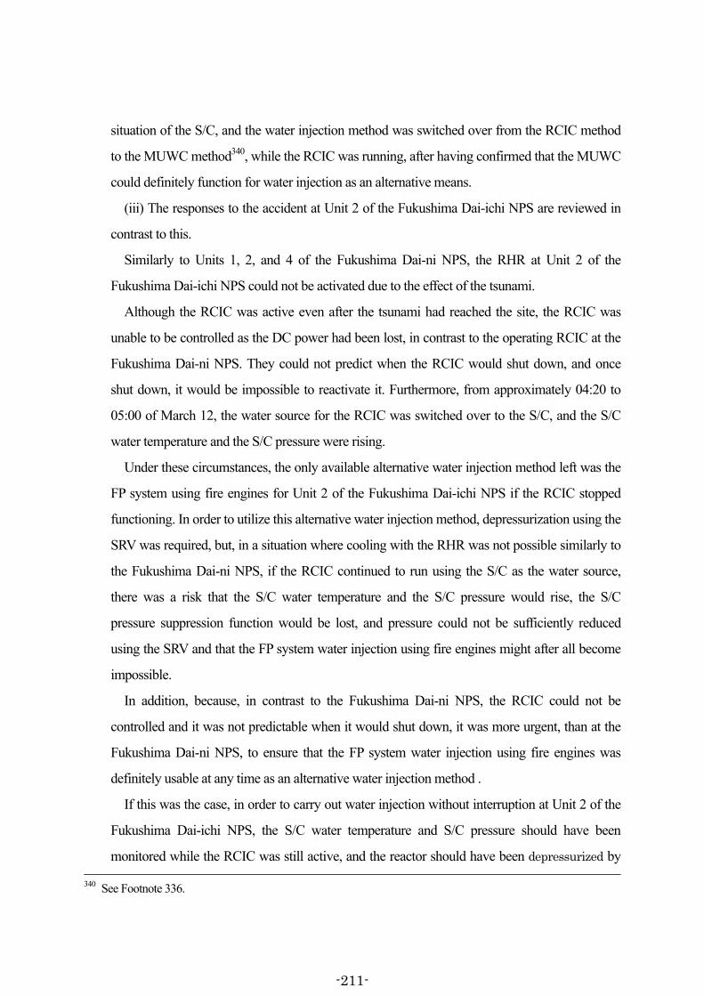
situation of the S/C, and the water injection method was switched over from the RCIC method
to the MUWC method340, while the RCIC was running, after having confirmed that the MUWC
could definitely function for water injection as an alternative means.
(iii) The responses to the accident at Unit 2 of the Fukushima Dai-ichi NPS are reviewed in
contrast to this.
Similarly to Units 1, 2, and 4 of the Fukushima Dai-ni NPS, the RHR at Unit 2 of the
Fukushima Dai-ichi NPS could not be activated due to the effect of the tsunami.
Although the RCIC was active even after the tsunami had reached the site, the RCIC was
unable to be controlled as the DC power had been lost, in contrast to the operating RCIC at the
Fukushima Dai-ni NPS. They could not predict when the RCIC would shut down, and once
shut down, it would be impossible to reactivate it. Furthermore, from approximately 04:20 to
05:00 of March 12, the water source for the RCIC was switched over to the S/C, and the S/C
water temperature and the S/C pressure were rising.
Under these circumstances, the only available alternative water injection method left was the
FP system using fire engines for Unit 2 of the Fukushima Dai-ichi NPS if the RCIC stopped
functioning. In order to utilize this alternative water injection method, depressurization using the
SRV was required, but, in a situation where cooling with the RHR was not possible similarly to
the Fukushima Dai-ni NPS, if the RCIC continued to run using the S/C as the water source,
there was a risk that the S/C water temperature and the S/C pressure would rise, the S/C
pressure suppression function would be lost, and pressure could not be sufficiently reduced
using the SRV and that the FP system water injection using fire engines might after all become
impossible.
In addition, because, in contrast to the Fukushima Dai-ni NPS, the RCIC could not be
controlled and it was not predictable when it would shut down, it was more urgent, than at the
Fukushima Dai-ni NPS, to ensure that the FP system water injection using fire engines was
definitely usable at any time as an alternative water injection method .
If this was the case, in order to carry out water injection without interruption at Unit 2 of the
Fukushima Dai-ichi NPS, the S/C water temperature and S/C pressure should have been
monitored while the RCIC was still active, and the reactor should have been depressurized by 340 See Footnote 336.
-211-

opening the SRV to the level to enable low pressure water injection before the pressure
suppression capability of the S/C was lost, and then they should have initiated the FP system
water injection using fire engines.
(iv) Nevertheless, at Unit 2 of the Fukushima Dai-ichi NPS, neither the S/C water
temperature nor the S/C pressure was monitored at all over approximately 48 hours from the
time when the water source had been switched over to the S/C until approximately 04:30 of
March 14.
Furthermore, even after commencing S/C monitoring, rapid depressurization and switchover
to the alternative water injection method were not carried out by overvaluing that the RCIC had
been running, if not under control. This was despite the awareness that the pressure suppression
capability of the S/C was significantly reduced and the S/C water temperature reached a point
where rapid depressurization using the SRV was required according to the EOP341.
Consequently, in a situation where the S/C pressure suppression capability was significantly
reduced after the RCIC had shut down at Unit 2 of the Fukushima Dai-ichi NPS, it took time to
depressurize the reactor, to commence alternative water injection through the FP system using
fire engines, and in addition they could not maintain sufficiently depressurized condition and
could only supply intermittent and insufficient alternative water injection.
It is conceivable to have come from the reason that the Dai-ichi NPS ERC and the shift team
were excessively reliant on the RCIC, which was running in imminent danger of shutting down
any time, and overly optimistic about the conditions of Unit 2, and thereby paying insufficient
attention to the need to continually monitor the S/C water temperature and the S/C pressure and
appropriately evaluate the pressure suppression capability of the S/C.
In contrast, at each Unit of the Fukushima Dai-ni NPS, the S/C water temperature and the
S/C pressure were continually monitored for grasping the S/C condition, while the RCIC was
active, the water injection method had been switched over from the RCIC to MUWC by
341 At Unit 2 of the Fukushima Dai-ichi NPS, the reactor pressure was 5.333 MPa gage and the S/C temperature
was about 146°C, when the measurement of the S/C water temperature started at about 07:00 on March 14, according to the plant parameter records. The Unit 2 EOP of the Fukushima Dai-ichi NPS specifies to implement rapid depressurization using the SRV by ensuring the operability of the low pressure water injection system or an alternative water injection line when the S/C water temperature rises to about 78°C at the reactor pressure of 5.333 MPa gage. It was clear therefore that, at this time point of the reactor pressure and the S/C temperature, Unit 2 of the Fukushima Dai-ichi NPS was in a situation where it must shift to the alternative water injection means using the fire protection system and fire engines by rapidly depressurizing the reactor.
-212-
depressurizing the reactor in stages using the SRV, before the S/C pressure suppression
capability was lost.
(v) In conclusion, even if the difference in situations is significant between the Fukushima
Dai-ni NPS, where there were more options available as they retained external power even after
the tsunami had reached the site, and Unit 2 of the Fukushima Dai-ichi NPS, which had to take
responses to the accident in a situation where all power was lost, the responses to the accident at
Unit 2 of the Fukushima Dai-ichi NPS did not have a sufficiently detailed grasp on the
conditions of the plant, when compared with those at the Fukushima Dai-ni NPS, and
accordingly they failed to anticipate the progress of events which would have allowed them to
take the necessary measures in advance. Consequently it cannot be considered that the
necessary measures were taken in order to inject water into the reactor without interruption.
-213-

This page intentionally left blank.