Embed Size (px)
Citation preview

II Year I Semester

ELECTRONIC DEVICES AND CIRCUITS Subject Code : UGEC3T0118 L T P C II Year/ I Semester 2 1 0 3
Prerequisite
Waves, Oscillations and Quantum Mechanics Basic Electrical Engineering
Course Objective
1. Summarize the electronic devices and circuits. 2. Examine the design and operation of circuits that utilize Active Components.
SYLLABUS UNIT- I [8 Hrs] Junction Diodes: Qualitative theory of P-N junction diode, V-I characteristics, and small signal switching models; Break down mechanisms in semiconductor diode, Special Diodes: Avalanche and Zener Break Down, Zener Diode Characteristics, Tunnel Diode, Characteristics with the help of Energy Band Diagrams, Varactor Diode, Light Emitting Diode and Photo Diode and solar cell UNIT- II [10 Hrs] Diode Circuits: Block Diagram of Regulated Power Supply, Half wave rectifier, Full wave rectifier, input and output wave forms, derivation of characteristics of rectifiers, Filters, Inductor filter, Capacitor filter, L-section filter, - section filter, Zener diode as
Voltage regulator Diode clippers, clipping at two independent levels, clamping operation, clamping circuits. UNIT- III [8 Hrs] Transistor Characteristics: Bipolar Junction Transistor: CE, CB and CC Configurations-V-I characteristics, FET and MOSFET-V-I characteristics, small signal models of BJT (h parameter model) UNIT- IV [8 Hrs] Transistor Biasing : Concept of Biasing- Load Line and Q-Point; Stability Factor, Biasing schemes for BJT amplifiers, Bias Stability and compensation techniques, Various configurations and their features. UNIT- V [10 Hrs] Analysis of Small Signal Amplifiers: Low frequency transistor model- estimation of voltage gain, current gain, input resistance and output resistance. Design procedure for particular specifications. Multistage amplifiers
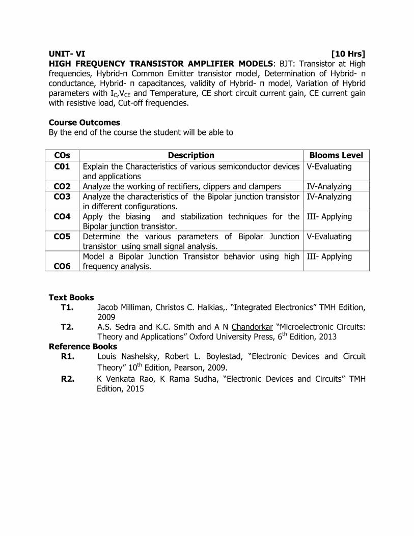
UNIT- VI [10 Hrs] HIGH FREQUENCY TRANSISTOR AMPLIFIER MODELS: BJT: Transistor at High frequencies, Hybrid-π Common Emitter transistor model, Determination of Hybrid- π conductance, Hybrid- π capacitances, validity of Hybrid- π model, Variation of Hybrid parameters with IC,VCE and Temperature, CE short circuit current gain, CE current gain with resistive load, Cut-off frequencies. Course Outcomes By the end of the course the student will be able to
COs Description Blooms Level
C01 Explain the Characteristics of various semiconductor devices and applications
V-Evaluating
CO2 Analyze the working of rectifiers, clippers and clampers IV-Analyzing
CO3 Analyze the characteristics of the Bipolar junction transistor in different configurations.
IV-Analyzing
CO4 Apply the biasing and stabilization techniques for the Bipolar junction transistor.
III- Applying
CO5 Determine the various parameters of Bipolar Junction transistor using small signal analysis.
V-Evaluating
CO6
Model a Bipolar Junction Transistor behavior using high frequency analysis.
III- Applying
Text Books
T1. Jacob Milliman, Christos C. Halkias,. “Integrated Electronics” TMH Edition, 2009
T2. A.S. Sedra and K.C. Smith and A N Chandorkar “Microelectronic Circuits: Theory and Applications” Oxford University Press, 6th Edition, 2013
Reference Books R1. Louis Nashelsky, Robert L. Boylestad, “Electronic Devices and Circuit
Theory” 10th Edition, Pearson, 2009.
R2. K Venkata Rao, K Rama Sudha, “Electronic Devices and Circuits” TMH Edition, 2015

DIGITAL LOGIC DESIGN
Subject Code : UGEC3T0218 L T P C II Year/ I Semester 3 0 0 3 Prerequisites
Mathematics –I
Mathematics –II
Course Objective:
1. To learn the methods for the design of digital circuits.
2. To provide fundamental concepts used in the design of digital systems.
SYLLABUS UNIT-I [8 Hrs] NUMBER SYSTEMS & CODES: Representation of numbers in different radix, conversation from one radix to another radix, r-1's compliments and r's compliments of signed numbers, weighted and non weighted codes , Gray code, Error detection, error correction codes, parity checking, Hamming code. UNIT-II [8 Hrs] BOOLEAN FUNCTIONS AND MINIMIZATION TECHNIQUES: Boolean theorems, principle of complementation & duality, De-Morgans theorems, Basic logic gates and Universal gates, NAND-NAND and NOR-NOR realizations, Standard SOP and POS, Minimization techniques: minimization of logic functions using Boolean theorems, minimization of switching functions using K-Map up to 5 variables, tabular minimization. UNIT-III [10 Hrs] COMBINATIONAL LOGIC DESIGN: Design of Half adder, full adder half subtractor, full subtractor, 4-bit binary subtractor, adder-subtractor circuit, BCD adder circuit, Excess 3 adder circuit, 4 bit parallel adder, Carry look-a-head adder circuit, applications of adders and subtractors. Decoders, 7 segment decoder, Encoders, priority encoder, Multiplexer, Demultiplexer, Comparators. UNIT-IV [8 Hrs] PLDs: Introduction, Types of PLDs, Basics structures of PROM, PAL, PLA, Realization of Boolean function using PROM, PAL, PLA , Comparison of PLDs UNIT-V [10 Hrs] SEQUENTIAL LOGIC DESIGN: Classification of sequential circuits, Latches and Flip-flops, Triggering, excitation tables, Asynchronous inputs, Conversion from one flip-flop to another flip flop. Registers-Types, modes of operations, bi-directional shift registers,

universal shift register, Counters-synchronous & Asynchronous counters, design of Mod-counters, Counters using shift registers, Serial binary adder. UNIT-VI [8 Hrs] STATE MACHINES Finite state machine; Analysis of clocked sequential circuits, state diagrams, state tables, reduction of state tables and state assignment, design procedures. Realization of circuits using various flip-flops. Melay to Moore conversion and vice-versa. Course Outcomes:
By the end of the course the student will be able to
COs Description Blooms Level
CO1 Utilize various number systems and coding techniques in digital design
III -Applying
CO2 Apply the concepts of Boolean algebra for the minimization of logic functions.
III -Applying
CO3 Design different combinational circuits using logic gates. VI- Creating
CO4 Build a combinational circuit using PLDs III -Applying
CO5 Design different sequential circuits using Flip-Flops VI- Creating
CO6 Model state machines from a description of a sequential logic function.
III -Applying
Text Books
T1. Hill and Peterson “Switching Theory and Logic Design” Mc-Graw Hill TMH edition
T2. A. Anand Kumar “Switching Theory and Logic Design” PHI, 2009 References
R1. RP Jain, “ Modern Digital Electronics”, TMH, 2009 R2. Fundamentals of Logic Design by Charles H.Roth Jr, Cenage Learning,
2010
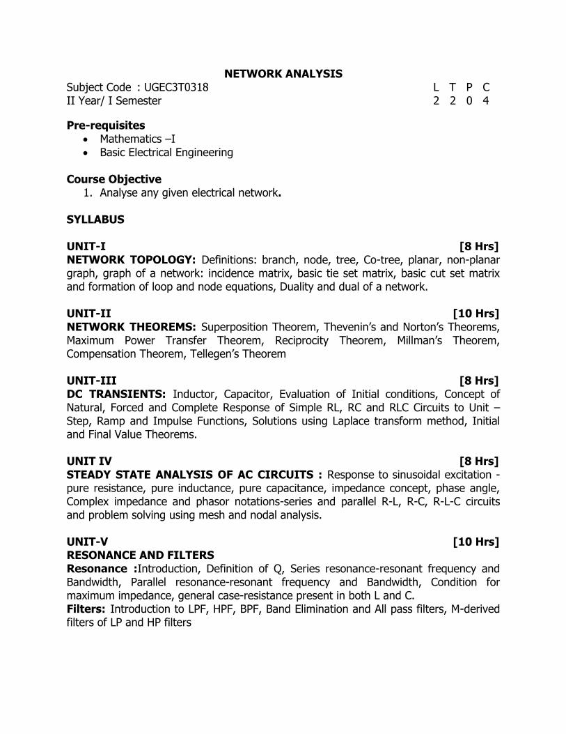
NETWORK ANALYSIS Subject Code : UGEC3T0318 L T P C II Year/ I Semester 2 2 0 4
Pre-requisites Mathematics –I Basic Electrical Engineering
Course Objective
1. Analyse any given electrical network. SYLLABUS UNIT-I [8 Hrs] NETWORK TOPOLOGY: Definitions: branch, node, tree, Co-tree, planar, non-planar graph, graph of a network: incidence matrix, basic tie set matrix, basic cut set matrix and formation of loop and node equations, Duality and dual of a network. UNIT-II [10 Hrs] NETWORK THEOREMS: Superposition Theorem, Thevenin’s and Norton’s Theorems, Maximum Power Transfer Theorem, Reciprocity Theorem, Millman’s Theorem, Compensation Theorem, Tellegen’s Theorem UNIT-III [8 Hrs] DC TRANSIENTS: Inductor, Capacitor, Evaluation of Initial conditions, Concept of Natural, Forced and Complete Response of Simple RL, RC and RLC Circuits to Unit –Step, Ramp and Impulse Functions, Solutions using Laplace transform method, Initial and Final Value Theorems. UNIT IV [8 Hrs] STEADY STATE ANALYSIS OF AC CIRCUITS : Response to sinusoidal excitation - pure resistance, pure inductance, pure capacitance, impedance concept, phase angle, Complex impedance and phasor notations-series and parallel R-L, R-C, R-L-C circuits and problem solving using mesh and nodal analysis. UNIT-V [10 Hrs] RESONANCE AND FILTERS Resonance :Introduction, Definition of Q, Series resonance-resonant frequency and Bandwidth, Parallel resonance-resonant frequency and Bandwidth, Condition for maximum impedance, general case-resistance present in both L and C. Filters: Introduction to LPF, HPF, BPF, Band Elimination and All pass filters, M-derived filters of LP and HP filters

UNIT-VI [18 Hrs] TWO PORT NETWORKS: Open circuit impedance parameters, Short circuit admittance parameters, Transmission parameters, Inverse transmission parameters, Hybrid parameters, Inverse hybrid parameters, Inter connection of two port networks, T-Network, π network Course Outcomes
Upon completion of the course, students are able to
COS Description Blooms Level
C01 Explain the fundamental concepts of Network Topology II-Understanding
CO2 Analyze the circuit using network theorems. IV-Analyzing
CO3 Evaluate transient response and steady state response of RL,RC and RLC circuits for DC Excitation
V-Evaluating
CO4 Explain the steady state analysis of AC circuits II-Understanding
CO5 Design the series resonant, parallel resonant circuits and filters
VI-Creating
CO6 Evaluate various parameters of two-port network V-Evaluating
Text Books
T1. A Sudhakar and Shyam Mohan, “Network Analysis”, 3rd Edition, TMH Edition, 2015.
T2. Willam H. Hayt Jr., and Jack E. Kemmerly, “Engineering Circuit Analysis”, 5th Edition, Mc Graw-Hill, 1993.
References
R1. John O’ Malley, “Basic Circuit Analysis”, 2nd Edition, schaum’s outline, Mc Graw-Hill,2011
R2. M. E. Vanvalkenburg, “Network Analysis”, 3rd Edition, PHI,2006

RANDOM VARIABLES AND TRANSFORMATION TECHNIQUES Subject Code : UGEC3T0418 L T P C II Year/ I Semester 2 1 0 3
Prerequisite Mathematics-I Mathematics -II
Course Objective
1. To provide an insight of fundamental concepts of single and multiple randomvariables
2. To apply and analyze the various transformation techniques on different types of signals
SYLLABUS UNIT I [8 Hrs] RANDOM VARIABLES AND DISTRIBUTION FUNCTIONS : Introduction, Definition of a Random Variable, Conditions for a Function to be a Random Variable, Discrete and Continuous, Mixed Random Variable, Distribution and Density functions, Properties, Binomial, Poisson, Uniform, Gaussian, Exponential, Rayleigh, Conditional Distribution, Conditional Density, Properties. UNIT II [8 Hrs] OPERATIONS ON SINGLE RANDOM VARIABLE : Introduction, Expected Value of a Random Variable, Function of a Random Variable, Moments about the Origin, Central Moments, Variance and Skew, Chebychev’s Inequality, Characteristic Function, Moment Generating Function, Transformations of a Random Variable: Monotonic Transformations for a Continuous Random Variable, Nonmonotonic Transformations of Continuous Random Variable. UNIT III [10 Hrs] MULTIPLE RANDOM VARIABLES: Vector Random Variables, Joint Distribution Function, Properties of Joint Distribution, Marginal Distribution Functions, Conditional Distribution and Density –Statistical Independence, Sum of two random variables, sum of several random variables, Central limit theorem, unequal and equal distributions. OPERATIONS ON MULTIPLE RANDOM VARIABLES: Expected Value of a Function of Random Variables: Joint Moments about the Origin, Joint Central Moments, Joint Characteristic Functions, Jointly Gaussian Random Variables: Two Random Variables case,NRandom Variable case, Properties, Transformations of Multiple Random Variables.

UNIT-IV: [8Hrs] FOURIER SERIES: Introduction to Periodic and Aperiodic Signals, Representation of Fourier series for Continuous time periodic signals, Exponential Fourier series, Trigonometric Fourier series and Cosine Fourier Series, Symmetry conditions: Even, Odd and Halfwave, Dirichlet’s conditions, properties of Fourier series, Complex Fourier spectrum, Power spectrum of periodic signals UNIT-V [8 Hrs] FOURIER TRANSFORMS: Deriving Fourier Transform from Fourier series, Fourier transform of arbitrary signal, Fourier transform of standard signals, Fourier transform of periodic signals, Properties of Fourier transforms, Inverse Fourier Transform, Introduction to Hilbert Transform, Energy density function of aperiodic signals. UNIT-VI [8 Hrs] LAPLACE TRANSFORMS: Introduction toLaplace transforms, Concept of region of convergence (ROC) for Laplace transforms, constraints on ROC for various classes of signals, Properties of LTs, Relation between LT and FT, Inverse Laplace transform, Realization of Physical system using FT & LT’s, Laplace transform of certain signals using waveform synthesis Note: The treatment of transformations in IV, V, VI units must be related to signals andsystems. Course Outcomes Upon completion of the course, students will be able to
COs Description Bloom’s Level
CO 1 Outline the concept of random phenomena and solve probabilistic problems.
II- Understanding
CO 2 Identify different types of random variables and analyze the parameters of single and multiple random variables.
III-Applying
CO 3 Analyze the different classes of signals in time and frequency domains.
IV-Analyzing
CO 4 Apply different types of Fourier series on time domain signals
III-Applying
CO 5 Apply FT and IFT onbroader class of signals III-Applying
CO 6 Apply LT and ILT onbroader class of signals III-Applying
TEXT BOOKS
T1. Peyton Z. Peebles, “Probability, Random Variables & Random Signal Principles”, 4th Edition, TMH, 2001.
T2. A.V. Oppenheim, A.S. Willsky and S.H. Nawab, “Signals and Systems”,PHI 2ndEdition

REFERENCE BOOKS R1. Athanasios Papoulis and S.Unnikrishna Pillai, “Probability, Random
Variables and Stochastic Processes”, 4th Edition, PHI, 2002. R2. B.P. Lathi, “Signals, Systems &Communications”,BS Publications, 2003.

SIGNALS & SYSTEMS Subject Code : UGEC3T0518 L T P C II Year/ I Semester 3 0 0 3
Prerequisites Students should have prior knowledge of
Mathematics-I Course Objective The objectives of this course are
1. To introduce the fundamentals concepts and techniques associated with the signals and systems.
2. To familiarize with concepts of vector space, inner product space and orthogonal series.
3. To enable the students to demonstrate the use of signals and systems in communications and signal processing
4. To develop mathematical skills to solve problems involving convolution, correlation and sampling.
SYLLABUS UNIT-I [10 Hrs] INTRODUCTION: Introduction to signals,Basic functions- Impulse function, Unit Step function and Signum function, Classification of signals, Periodic and aperiodic Signals, Power and Energy of signals, Operations on signals: Time Shifting, Scaling and reversal, Representation of signals using impulse function. SIGNAL ANALYSIS: Analogy between vectors and signals, orthogonal signal space, Orthoganality of signals, Signal approximation using orthogonal functions, Orthogonality in complex functions. UNIT-II [8 Hrs] SIGNAL TRANSMISSION THROUGH LINEAR SYSTEMS: Introduction to systems,Classification of Systems, System Properties, Response of a system, Impulse and Step responses of LTI System, Response Filter characteristics of linear systems. Distortion less transmission through a system, Signal bandwidth, System bandwidth, Ideal LPF, HPF and BPF characteristics, Paley-Wiener criterion for physical realization. UNIT-III [8 Hrs] CONVOLUTION AND CORRELATION: Concept of convolution in time domain and frequency domain, Convolution property of Fourier Transform, Correlation, Relation between convolution and correlation, Cross correlation and Auto correlation of functions, Properties of correlation functions, Energy density spectrum, Power density
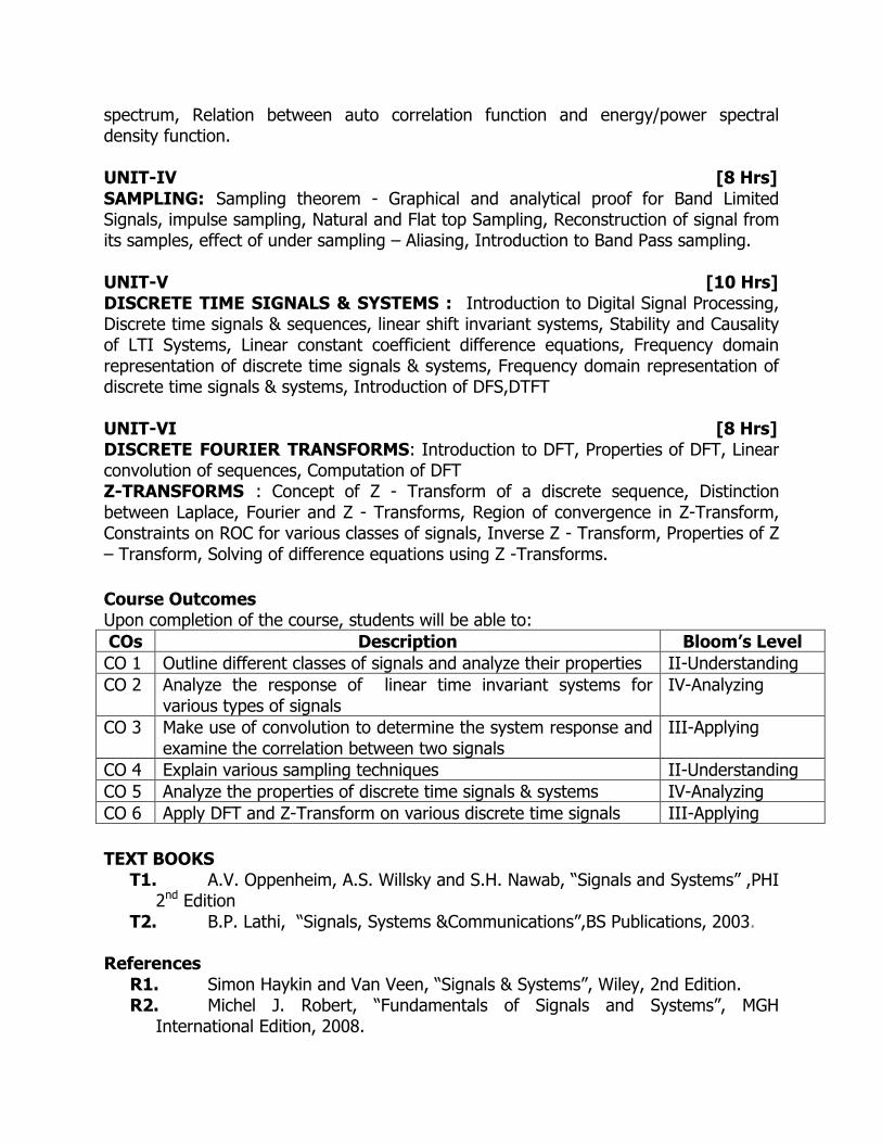
spectrum, Relation between auto correlation function and energy/power spectral density function. UNIT-IV [8 Hrs] SAMPLING: Sampling theorem - Graphical and analytical proof for Band Limited Signals, impulse sampling, Natural and Flat top Sampling, Reconstruction of signal from its samples, effect of under sampling – Aliasing, Introduction to Band Pass sampling. UNIT-V [10 Hrs] DISCRETE TIME SIGNALS & SYSTEMS : Introduction to Digital Signal Processing, Discrete time signals & sequences, linear shift invariant systems, Stability and Causality of LTI Systems, Linear constant coefficient difference equations, Frequency domain representation of discrete time signals & systems, Frequency domain representation of discrete time signals & systems, Introduction of DFS,DTFT UNIT-VI [8 Hrs] DISCRETE FOURIER TRANSFORMS: Introduction to DFT, Properties of DFT, Linear convolution of sequences, Computation of DFT Z-TRANSFORMS : Concept of Z - Transform of a discrete sequence, Distinction between Laplace, Fourier and Z - Transforms, Region of convergence in Z-Transform, Constraints on ROC for various classes of signals, Inverse Z - Transform, Properties of Z – Transform, Solving of difference equations using Z -Transforms.
Course Outcomes Upon completion of the course, students will be able to:
COs Description Bloom’s Level
CO 1 Outline different classes of signals and analyze their properties II-Understanding
CO 2 Analyze the response of linear time invariant systems for various types of signals
IV-Analyzing
CO 3 Make use of convolution to determine the system response and examine the correlation between two signals
III-Applying
CO 4 Explain various sampling techniques II-Understanding
CO 5 Analyze the properties of discrete time signals & systems IV-Analyzing
CO 6 Apply DFT and Z-Transform on various discrete time signals III-Applying
TEXT BOOKS T1. A.V. Oppenheim, A.S. Willsky and S.H. Nawab, “Signals and Systems” ,PHI
2nd Edition T2. B.P. Lathi, “Signals, Systems &Communications”,BS Publications, 2003.
References
R1. Simon Haykin and Van Veen, “Signals & Systems”, Wiley, 2nd Edition. R2. Michel J. Robert, “Fundamentals of Signals and Systems”, MGH
International Edition, 2008.

ELECTRONIC DEVICES AND CIRCUITS LAB
Subject Code : UGEC3P0618 L T P C II Year/ I Semester 0 0 3 1.5
Pre-requisites Electronic Devices and Circuits Network Analysis
Laboratory Objective
1. Illustrate the principles, operation and application of the basic electronic components.
2. Analyze the Characteristics of the active devices and frequency response of different amplifiers.
EXPERIMENTS (minimum of Ten) PART A: ELECTRONIC WORKSHOP PRACTICE 1. Identification, Specifications, Testing of R, L, C Components (Colour Codes),
Potentiometers, Switches (SPDT, DPDT, and DIP), Coils, Gang Condensers, Relays, Bread Boards.
2. Identification, Specifications and Testing of Active Devices, Diodes, BJTs, JFETs, Power Transistors, LEDs, LCDs, Optoelectronic Devices, UJT.
3. Soldering practice – Simple Circuits using active and passive components. 4. Single layer and Multi-layer PCBs (Identification and Utility). 5. Study and operation of Ammeters, Voltmeters, Transformer, Analog and Digital
Multimeters, Function Generator, Regulated Power Supplies and CRO. PART B: Experiments (minimum of Ten) 1. PN Junction diode characteristics (Static and Dynamic Resistance and Cut-in Voltage ) 2. Zener diode Reverse Bias characteristics and Zener Diode as a regulator 3. Half wave Rectifier (with & without filters ) 4. Center Tap Full wave Rectifier with filters (with & without filters ) 5. Bridge Rectifier with filters (with & without filters ) 6. Transistor CB characteristics (Input and Output) & h Parameter calculations 7. Transistor CE characteristics (Input and Output) & h Parameter calculations 8. FET characteristics (Drain, Transfer characteristics) and calculate Drain
Resistance (rd), Trans Conductance (gm), Amplification factor (µ).
9. Emitter Characteristics of UJT 10. Design and verify Self Bias Circuit. ( Q - Point) 11. Frequency response of CE Amplifier (With and without Emitter bypass capacitor)
and calculate Bandwidth, input and output impedances.

12. Frequency response of CC Amplifier (Emitter Follower) and calculate Bandwidth, input and output impedances.
13. One side and Two side Clippers 14. Positive and Negative Clamper Circuits
Laboratory Outcomes After completion of the course the student will be able to
COs Description BLOOMS Level
LO 1 Classify and test different Passive Components & Active devices
IV-Analyze
LO 2 Illustrate the characteristics of diodes and their applications II-Understand
LO 3 Analyze the input and output characteristics of BJT, FET, UJT and SCR
IV-Analyze
LO 4 Analyze the frequency response of BJT and FET Amplifier IV-Analyze

DIGITAL ELECTRONICS LAB
Subject Code : UGEC3P0718 L T P C II Year/ I Semester 0 0 3 1.5
Prerequisites Digital Logic Design
Laboratory Objectives
To design and realize basic digital combinational and sequential circuits. To verify the functionality of basic digital combinational and sequential circuits
Experiments (minimum of Ten) 1. Verify
(a) Basic Logic gates (b) Demorgan's Theorem for 2 variables. 2. Design and implementation of code converters using logic gates (a) BCD to excess-3 code and vice versa (b) Binary to gray and vice-versa 3. Design and implementation of 16 bit odd/even parity checker generator using
IC74180. 4. Design and implementation of Adders and Subtractors using logic gates. 5. Design and implementation of 4 bit binary Adder/ subtractor and BCD adder
using IC 7483 6. Design and implementation of Encoder and Decoder using logic gates and study
of IC7445 and IC74147 7. Design and implementation of Multiplexer and De-multiplexer using logic gates
and study of IC74150 and IC 74154 8. Design and Implementation of 8-bit Magnitude Comparator using IC 7485. 9. Verification of state tables of RS, JK, T and D flip-flops with minimum NAND &
NOR gates. 10. Design and implementation of n-bit synchronous up/down counter 11. Implementation of Uni/Bidirectional shift register.
Laboratory Outcomes After completion of the course, the students will be able to
LOs Description Blooms Level
LO1 Solve the Boolean algorithms using practical logic gates. VI- Creating
LO2 Demonstrate the truth table of various expressions and combinational circuits using logic gates.
II -Understanding
LO3 Design and verify basic combinational logic circuits using Practical ICs.
VI- Creating
LO4 Design and verify basic sequential logic circuits using Practical ICs.
VI- Creating

SIGNAL PROCESSING SIMULATION LAB
Subject Code : UGEC3P0818 L T P C II Year/ I Semester 0 0 3 1.5
Prerequisites 1. Random Variables and Transformation Techniques 2. Signals and Sysems
Laboratory Objectives
1. To represent continuous time, discrete time signals & systems encountered in
engineering using MATLAB programming.
2. To make use of MATLAB programming to examine the behavior of continuous
time, discrete time signals and systems encountered in engineering.
Experiments (minimum of Ten)
1. Operations on Matrices, Loops & Functions
2. Generation of basic signals
3. Operations on signals
4. Verification of properties of signals
5. Convolution between signals
6. Correlation of signals
7. Power Spectral Density of periodic signals
8. Verification of sampling theorem
9. Discrete Fourier Transform & Inverse Discrete Fourier Transform
10. Z-Transform & Inverse Z-Transform
11. Fourier Transform
12. Laplace Transform
13. Verification of Modulation Property (Frequency Shifting Property)
Laboratory Outcomes Upon completion of the Laboratory, students will be able to
LOs Description Bloom’s Level
LO 1 Construct all classes of discrete time signals using MATLAB. III-Applying
LO 2 Analyze response of an LTI system for different inputs. IV-Analyzing
LO 3 Examine magnitude and phase responses of a signal. IV-Analyzing
LO 4 Design Simulink models for analysis of signals and systems. VI-Creating

II Year II Semester

ANALOG & PULSE CIRCUITS
Subject Code : UGEC4T0118 L T P C II Year/ II Semester 3 0 0 3
PREREQUISITES
Electronic Devices & Circuits
Network Analysis
COURSE OBJECTIVES
1. Outlines the basic concepts of feedback amplifiers and power amplifiers
importance in electronic circuits.
2. Develops student’s ability to solve problems in electronic circuits.
3. Demonstrates the basic concepts of linear wave shaping circuits and
multivibrator circuits.
SYLLABUS
UNIT- I [8 Hrs] FEEDBACK AMPLIFIERS: Basic Amplifiers: Voltage amplifier, Current amplifier, Tran conductance and trans-resistance amplifier, Feedback topologies: Voltage series, current series, voltage shunt, current shunt, effect of negative feedback on amplifier characteristics, concept of stability. UNIT- II [8 Hrs] OSCILLATORS: Review of the basic concept, Barkhausen criterion, RC oscillators (phase shift, Wien bridge), LC oscillators (Hartley, Colpitts), non-sinusoidal oscillators (crystal, sweep generators). UNIT- III [10 Hrs] POWER AMPLIFIERS : Various classes of operation (Class A, B, AB, C etc.), Distortion in power amplifiers, Class A Power Amplifier and Efficiency, Class-B Push-Pull Amplifier and Class-B Complementary Symmetry Amplifier with Efficiency, Class AB Amplifier and Efficiency. UNIT- IV [8 Hrs] LINEAR WAVE SHAPING: High pass, low pass RC circuits, their response for sinusoidal, step, pulse, square and ramp inputs, high pass RC circuit as differentiator and low pass RC circuit as integrator, attenuators. Switching Characteristics of Transistors: transistor-switching times, design of transistor as a switch, transistor in saturation.

UNIT- V [10 Hrs] BISTABLE MULTIVIBRATORS: Design and Analysis of Fixed-bias& self-bias transistor binary, Commutating capacitors, Triggering of Binary, Triggering Unsymmetrically through a Unilateral Device, Triggering Symmetrically through a Unilateral Device, Transistor Schmitt trigger and its applications. UNIT- VI [10 Hrs] MONOSTABLE & ASTABLE MULTIVIBRATORS: Collector coupled Monostable multivibrator, Expression for the gate width, waveforms at bases and collectors; Collector coupled Astable multivibrator-expression for the frequency of operation, waveforms at bases and collectors, Astable multivibrator as a voltage to frequency convertor; Design and analysis related problems on those circuits. COURSE OUTCOMES
Upon completion of the course, students will be able to
COs Description Blooms Level
C0 1 Analyze different types of negative feedback amplifier electronic circuits
IV- Analyzing
CO 2 Design different types of Oscillators VI- Creating
CO 3 Explain the operation Power amplifiers V-Evaluating
CO 4 Design and analyze linear wave shaping circuits VI- Creating
CO 5 Analyze Bistable Multivibrators IV- Analyzing
CO 6 Analyze Astable and Monostable Multivibrators IV- Analyzing
Text Books: T1. Jacob Milliman, Christos C. Halkias,. “Integrated Electronics” TMH Edition,
2009 T2. Jacob Millman, Herbert Taub, Mothiki S. Prakash Rao “Pulse, Digital and
Switching Waveforms”, TMH, 3rd edition, 2008 Reference Books
R1. A.S. Sedra and K.C. Smith and A N Chandorkar “Microelectronic Circuits: Theory and Applications” Oxford University Press, 6th Edition, 2013
R2. A Anand Kumar, “Pulse and Digital Circuits”, Prentice Hall of India, India. 2005

ANALOG AND DIGITAL COMMUNICATIONS
Subject Code : UGEC4T0218 L T P C II Year/ II Semester 2 1 0 3
PREREQUISITES
Electronic Devices and Circuits
Signals and Systems
Random Variables and Transform Techniques
COURSE OBJECTIVES: This course provides
1. Introduction to the basic principles and techniques used in analog and
communications.
2. Introduction to analog and digital modulation techniques, and multiplexing
techniques.
SYLLABUS
UNIT-I [10 Hrs]
AMPLITUDE MODULATION : Introduction and overview of basic communication
system, Frequency bands and their applications, Need for Modulation, Amplitude
Modulation, Modulation Index, Spectrum of AM Signal, Power Calculations in AM
Systems, Modulators and Demodulators (Diode detector),DSB-SC Signal and its
Spectrum, Balanced Modulator, Synchronous Detectors. SSB Signal, Comparison of AM
Techniques, Application of AM Systems, block diagram of AM Transmitter and receiver.
UNIT-II [10 Hrs]
ANGLE MODULATION: Angle Modulation, Narrow Band and Wideband FM, Spectrum of
an FM Signal. Indirect method of Frequency Modulation (Armstrong Method), Frequency
Multiplication, FM Demodulation: Balanced Slope Detector, Foster Seeley Discriminator,
Ratio Detector, FM Demodulation using PLL, Pre – emphasis and De – emphasis,
Comparison of FM and AM, block diagram of FM Transmitter and receiver.
UNIT-III [8 Hrs]
PULSE ANALOG MODULATION: Time Division Multiplexing, Types of Pulse modulation,
PAM (Single polarity, double polarity), Generation & demodulation of PWM, Generation
and demodulation of PPM, Comparison of PAM, PWM and PPM systems, TDM Vs FDM.
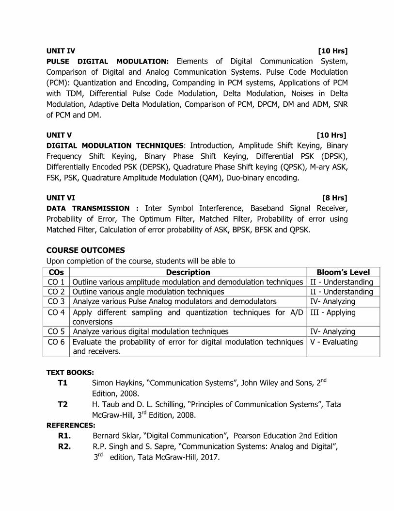
UNIT IV [10 Hrs]
PULSE DIGITAL MODULATION: Elements of Digital Communication System,
Comparison of Digital and Analog Communication Systems. Pulse Code Modulation
(PCM): Quantization and Encoding, Companding in PCM systems, Applications of PCM
with TDM, Differential Pulse Code Modulation, Delta Modulation, Noises in Delta
Modulation, Adaptive Delta Modulation, Comparison of PCM, DPCM, DM and ADM, SNR
of PCM and DM.
UNIT V [10 Hrs]
DIGITAL MODULATION TECHNIQUES: Introduction, Amplitude Shift Keying, Binary
Frequency Shift Keying, Binary Phase Shift Keying, Differential PSK (DPSK),
Differentially Encoded PSK (DEPSK), Quadrature Phase Shift keying (QPSK), M-ary ASK,
FSK, PSK, Quadrature Amplitude Modulation (QAM), Duo-binary encoding.
UNIT VI [8 Hrs]
DATA TRANSMISSION : Inter Symbol Interference, Baseband Signal Receiver,
Probability of Error, The Optimum Filter, Matched Filter, Probability of error using
Matched Filter, Calculation of error probability of ASK, BPSK, BFSK and QPSK.
COURSE OUTCOMES
Upon completion of the course, students will be able to
TEXT BOOKS:
T1 Simon Haykins, “Communication Systems”, John Wiley and Sons, 2nd
Edition, 2008.
T2 H. Taub and D. L. Schilling, “Principles of Communication Systems”, Tata
McGraw-Hill, 3rd Edition, 2008.
REFERENCES:
R1. Bernard Sklar, “Digital Communication”, Pearson Education 2nd Edition
R2. R.P. Singh and S. Sapre, “Communication Systems: Analog and Digital”,
3rd edition, Tata McGraw-Hill, 2017.
COs Description Bloom’s Level
CO 1 Outline various amplitude modulation and demodulation techniques II - Understanding
CO 2 Outline various angle modulation techniques II - Understanding
CO 3 Analyze various Pulse Analog modulators and demodulators IV- Analyzing
CO 4 Apply different sampling and quantization techniques for A/D conversions
III - Applying
CO 5 Analyze various digital modulation techniques IV- Analyzing
CO 6 Evaluate the probability of error for digital modulation techniques and receivers.
V - Evaluating

EM WAVES & TRANSMISSION LINES Subject Code : UGEC4T0318 L T P C II Year/ II Semester 2 2 0 4
Prerequisite Waves, Oscillations and Quantum Mechanics Mathematics - I
Course Objective
To understand and develop various engineering applications involving electromagnetic fields
To understand foundations of electromagnetism and its practice in modern communications such as wireless, fiber optics and electromagnetic structures.
SYLLABUS UNIT –I [8 Hrs] TRANSMISSION LINES–I: Types, Parameters, Transmission Line Equations, Primary & Secondary Constants, Expression for Characteristic Impedance, Propagation constant, Phase and Group Velocities, Infinite line Concepts, losslessness/Low loss Characterization, Distortion- condition for Distortionlessness and minimum Attenuation, Loading – Types of Loading. UNIT II [8 Hrs] TRANSMISSION LINES – II: Input Impedance Relations, SC and OC lines, Reflection Coefficient, VSWR. UHF Lines as circuit elements; λ/8, λ/4 and λ/2 Lines – impedance Transformations., Smith Chart – Configuration & Applications, Single Stub Matching. UNIT III [8 Hrs] ELECTROSTATICS: Review of Vector analysis and coordinate systems (Cartesian, Cylindrical and Spherical co-ordinate systems). Coulomb's law, Electric field intensity, Electric flux and electric flux density; Gauss's law and its applications, Electric potential, Maxwell’s two equations for electrostatic fields, Energy density, Convection and Conduction currents, Dielectric Constant, Continuity equation, Relaxation time, Poisson's and Laplace's equations, Capacitance – Parallel Plate, Coaxial, Spherical Capacitors. UNIT IV [8 Hrs] MAGNETOSTATICS: Biot-Savart's law, Ampere's Circuital law and its applications, Magnetic flux and magnetic flux density, Maxwell’s two equations for Magnetostatic Fields, Magnetic scalar and vector magnetic potentials, Forces due to magnetic fields, Ampere’s Force Law, Inductances and Magnetic Energy. UNIT V [8 Hrs] MAXWELL'S EQUATIONS: Faraday’s Law and Transformer EMF, Inconsistency of Ampere’s Law and Displacement Current Density, Maxwell's equations in different forms and word statements. Conditions at Boundary Surface: Dielectric-Dielectric and Dielectric-Conductor Interfaces.

UNIT VI [8 Hrs] EM WAVE CHARACTERISTICS: Wave equations for Conducting and perfect dielectric media, Uniform plane waves – Definition, All relations between E & H. Sinusoidal Variations. Wave Propagation in lossless and Conducting Media. Conductors & Dielectrics – Characterization, Wave Propagation in good conductors & Good Dielectrics, Polarization, Poynting vector and complex Poynting theorem – Applications, Power Loss in a Plane Conductor, Surface Impedance, Reflection & Refraction of Plane Waves – Normal and Oblique incidence for both Perfect Conductor and Perfect Dielectrics, Brewster Angle, Critical Angle and total internal reflection.
Course Outcomes Upon completion of the course, students will be able to
COS Description Bloom’s Level
CO 1 Illustrate the characteristics of transmission lines II- Understanding
CO 2 Evaluate the basic transmission line parameters for various applications
V- Evaluating
CO 3 Explain the laws and principles of electrostatic fields II- Understanding
CO 4 Demonstrate laws and principles of magnetostatic fields II- Understanding
CO 5 Formulate the Maxwell’s equations for time varying Electromagnetic fields
VI- Creating
CO 6 Apply the Maxwell’s Equations to characterize the wave propagation in different media interfaces
III- Applying
Text Books T1. William H Hayt. and John A Buck, “Engineering Electromagnetics” TMH, 7th
Edition T2. EC Jordan and K G Balmain, “Electromagnetic Waves and Radiating Systems”,
PHI, 2nd Edition Reference Books
R1. Mathew N O Sadiku, “Principles of Electromagnetics” Oxford University Press, 4th Edition
R2. GSN Raju, “Electromagnetic Field Theory and Transmission lines”, Pearson Education, 2013
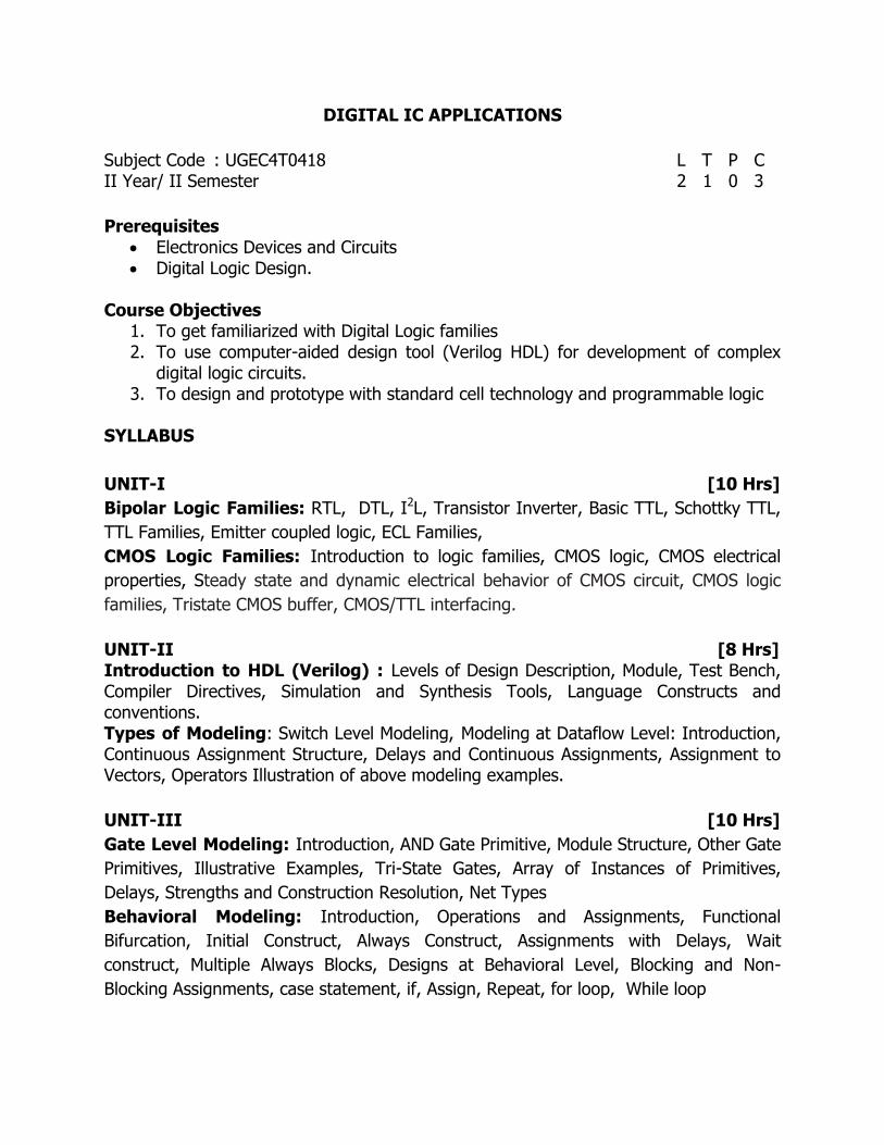
DIGITAL IC APPLICATIONS
Subject Code : UGEC4T0418 L T P C II Year/ II Semester 2 1 0 3
Prerequisites
Electronics Devices and Circuits Digital Logic Design.
Course Objectives
1. To get familiarized with Digital Logic families 2. To use computer-aided design tool (Verilog HDL) for development of complex
digital logic circuits. 3. To design and prototype with standard cell technology and programmable logic
SYLLABUS
UNIT-I [10 Hrs]
Bipolar Logic Families: RTL, DTL, I2L, Transistor Inverter, Basic TTL, Schottky TTL,
TTL Families, Emitter coupled logic, ECL Families,
CMOS Logic Families: Introduction to logic families, CMOS logic, CMOS electrical
properties, Steady state and dynamic electrical behavior of CMOS circuit, CMOS logic
families, Tristate CMOS buffer, CMOS/TTL interfacing.
UNIT-II [8 Hrs] Introduction to HDL (Verilog) : Levels of Design Description, Module, Test Bench, Compiler Directives, Simulation and Synthesis Tools, Language Constructs and conventions. Types of Modeling: Switch Level Modeling, Modeling at Dataflow Level: Introduction, Continuous Assignment Structure, Delays and Continuous Assignments, Assignment to Vectors, Operators Illustration of above modeling examples.
UNIT-III [10 Hrs]
Gate Level Modeling: Introduction, AND Gate Primitive, Module Structure, Other Gate
Primitives, Illustrative Examples, Tri-State Gates, Array of Instances of Primitives,
Delays, Strengths and Construction Resolution, Net Types
Behavioral Modeling: Introduction, Operations and Assignments, Functional
Bifurcation, Initial Construct, Always Construct, Assignments with Delays, Wait
construct, Multiple Always Blocks, Designs at Behavioral Level, Blocking and Non-
Blocking Assignments, case statement, if, Assign, Repeat, for loop, While loop

UNIT-IV [10 Hrs]
Combinational circuit design using Verilog HDL: Parallel Adder cum Subtractors
circuit, Carry looks ahead Adder, Decoders, Encoders, Multiplexers, Demultiplexers,
comparators, code converters, Priority Encoder, Dual Priority Encoder, Floating Point
encoder, Barrel shifter, one bit counter. Parity circuits, Verilog HDL program for the
above combinational logic circuits with relevant ICs
UNIT-V [10 Hrs]
Sequential logic circuit design using Verilog HDL: SSI latches and Flip-flops,
Counters, Design of Counters using Digital ICs, Ring Counter, Johnson counter, Modulus
N Synchronous counters, MSI Registers, Shift Registers, Modes of operation of shift
registers, Universal Shift registers. Verilog HDL program for the sequential logic circuits
with relevant ICs.
UNIT-VI [8 Hrs]
MEMORIES: ROMs - Internal structure, 2D-decoding commercial types, timing and
applications.
Static RAM: Internal structure, SRAM timing, standard SRAMS, synchronous SRAMS.
Dynamic RAM: Internal structure, timing, synchronous DRAMs
Course Outcomes Upon completion of the course, students will be able to
COs Description Blooms Level
CO 1 Illustrate characteristics of Bipolar and CMOS logic families. II-Understanding
CO 2 Demonstrate different design constraints in Verilog HDL II-Understanding
CO 3 Categorize different modeling styles IV-Analyzing
CO 4 Design combinational circuits using digital ICs in Verilog HDL VI-Creating
CO 5 Design sequential circuits using digital ICs in Verilog HDL VI-Creating
CO 6 Illustrate the different memories in digital ICs II-Understanding
Text Books T1. John F. Wakerly, “Digital Design Principles & Practices”, PHI Education, 3rd
Ed., 2005. T2. Zainalabdien Navabi, “Verilog Digital System Design”, TMH, 2nd Edition.
Reference Books
R1. Samir Palnitkar, “Verilog HDL” Pearson Education, 2nd Edition, 2009. R2. J. Bhasker, “A Verilog HDL Primer” , Star Galaxy Publishing, 3rd Edition

ANALOG COMMUNICATIONS LAB Subject Code : UGEC4P0518 L T P C II Year/ II Semester 0 0 3 1.5
Prerequisites
Analog Communications Operation of CRO, Function Generator
Laboratory Objectives: The objectives of this course are
1. To give experimental exposure about analog modulation techniques such as linear and non linear modulation techniques.
2. To give experimental exposure about pluse modulation techniques such as PAM, PWM and PPM.
EXPERIMENTS: (Any 10 Experiments to be conducted) HARDWARE
1. Amplitude Modulation &Demodulation (Hardware and Software) 2. AM-DSBSC Modulation & Demodulation (Hardware and Software) 3. Frequency Modulation & Demodulation (Hardware and Software) 4. Diode detector 5. Spectrum analysis using Spectrum analyzer 6. Pre-emphasis & De-emphasis 7. AGC circuits 8. Frequency Mixer 9. Squelch circuit 10. Pulse Amplitude Modulation and Demodulation. 11. Pulse Width Modulation and Demodulation. 12. Pulse Position Modulation and Demodulation. 13. Single sideband Modulation and Demodulation
Laboratory Outcomes Upon completion of the lab, students will be able to
LOs Description Bloom’s Level
LO 1 Experiment with different Analog modulators and
demodulators
III - Applying
LO 2 Make use of functionalities of various components used in analog transmitters and receivers
III - Applying
LO 3 Analyze Analog modulated signals with simulation tool IV- Analyzing
LO 4 Apply the theoretical concepts for designing of analog modulators and demodulators with Simulink
III - Applying

ANALOG & PULSE CIRCUITS LAB Subject Code : UGEC4P0618 L T P C II Year/ II Semester 0 0 3 1.5
Pre-requisites Electronic Devices and Circuits
Network Analysis
Laboratory Objectives: This course intent to provide
1. An overview of amplifiers, feedback amplifiers Oscillators and tuned amplifiers
2. Ability to Design Linear Wave Shaping Circuits.
3. Ability to design Schmitt Trigger and Relaxation Oscillator Circuits.
EXPERIMENTS (Any 10 Experiments)
I. ELECTRONIC CIRCUITS Design and simulation in simulation Laboratory using Multisim OR Pspice OR Equivalent simulation software (Simulate any five experiments using software) ANALYSIS AND DESIGN OF
1. CE Amplifier 2. Two stage RC coupled Amplifier. 3. Voltage series Feedback Amplifier/ Current shunt Feedback Amplifier 4. RC Phase Shift Oscillator using BJTs. 5. Darlington Emitter Follower Circuit. 6. Complementary Symmetry Class B Push Pull Power Amplifier. 7. Single Tuned Voltage Amplifier.
II. Pulse and Digital Circuits (Any five experiments using Hardware) 1. Linear wave shaping (Diff. Time Constants, Differentiator, Integrator). 2. Astable Multivibrator 3. Monostable Multivibrator 4. Bistable Multivibrator. 5. Schmitt Trigger. 6. UJT Relaxation Oscillator.
Laboratory Outcomes
Upon completion of the course, students will be able to
LOs Description Blooms Level
LO 1 Apply the fundamental design concepts on electronic circuits III-Applying
LO 2 Analyze the problems such as amplifiers and oscillators by adapting modern engineering tool like multi-sim and ADK kits
IV-Analyzing
LO 3 Design and Analyze linear wave shaping circuits VI-Creating
LO 4 Design and analyze Multivibrators, Schmitt Trigger and Relaxation oscillator
VI-Creating

DIGITAL IC APPLICATIONS LAB
Subject Code : UGEC4P0718 L T P C II Year/ II Semester 0 0 3 1.5
Prerequisites: Digital Logic Design.
Laboratory Objectives:
The main objective of this lab course is to gain the practical hands on experience by exposing the students to various digital IC applications.
Experiments (Minimum 10 Experiments)
1. Study of Field Programmable Gate Array. 2. Realization and FPGA implementation of Logic gates. 3. Design of and FPGA implementation of Adders and Subtractors. 4. Design of 4 x16 decoder using 3 x 8 decoders. 5. Design a 3 bit priority encoder. 6. Design a 16 bit comparator using 4 bit Comparators 7. (a) Design a 16 x 1 multiplexer using 8 x 1 multiplexer.
(b) Design of 1 x 16 demultiplexer using 1x8 multiplexer. 8. Design a 4 – bit Gray to Binary and Binary to Gray Converter. 9. Design a D/T flip flop using J-K flip flop. 10. Design a clock generator using NAND / NOR gates. 11. (a) Design an 8 bit parallel load and serial out shift register using two 4 bit shift
register. (b) Design an 8 bit Serial in and serial out shift register using two 4 bit shift register.
12. Design a Ring counter using a 4-bit shift register. 13. Design a Decade counter. 14. Design a RAM (16x4).
Laboratory Outcomes Upon completion of the Laboratory, students will be able to
LOs Description Blooms Level
LO1 Explain the Verilog Hardware Description Language. II-Understanding
LO2 Design, simulate and synthesize combinational using Verilog
HDL.
VI-Creating
LO3 Design, simulate and synthesize sequential circuits using
Verilog HDL.
VI-Creating
LO4 Make use of FPGA boards for implementation of Digital
Circuits
III-Applying