Embed Size (px)
Citation preview

AD-A277 191III I I I III IIII111 1
TECHNICAL REPORTNaval Facilities Engineering Service Center, Port Hueneme, CA 93043-4328
BOND STRESS-SLIPCHARACTERISTICS
OF FRP REBARS
TR-2013-SHR -.
February 1994 A
By L.J. Malvar
Sponsored byOffice of Naval Research
The bond characteristics of four different types of glass fiber-reinforced plastic (GFRP) rebars withdifferent surface deformations were analyzed experimentally. Local bond stress-slip data, as well as bondstress-radial deformation data, needed for constitutive modeling of the interface mechanics, were obtained forvarying levels of confining pressure. In addition to bond stress and slip, radial stress and radial deformationwere considered fundamental variables needed to provide for configuration-independent relationships. Each testspecimen consisted of a #6 GFRP rebar embedded in a 3-inch-diameter, 4-inch-long cracked concrete cylindersubjected to a controlled, constant amount of confining axisymmetric radial pressure. Only 2.625 inches (theequivalent of five steel bar lugs) of contact were allowed between the bar and the concrete. For each rebar type,bond stress-slip and bond stress-radial deformation relationships were obtained for five levels of confining ax-isynmetric radial pressure. It was found that small surface indentations are sufficient to yield bond strengthscomparable to that of steel bars. Effects of the deformations on tensile properties are discussed. It is also shownthat radial pressure is an important parameter which can increase the bond strength threefold.
Approved for public release; distribution unlimited.

C% 14 10 4 8u
• -S 'o ý 'ao.-
i >
ui0 4(0
0C• --- =_o _E E ~~ () ~ - ~ ~ ~ O W - ~ ME .
Ill , 0C'-0I' ["N S 0e4 Z ONlOlO- l4 5
-• 19181 1 1 4 i,3 12 I o 1
S EEEE E 0
10
kn a U) mCDcX~z WO N - j 0n
Uol , 01o.1 °
3 ~ 0 _ 00 ~w.
~ ~ 2LL
'1E 031E
IFn FwmAovedREPORT DOCUMENTATION PAGE ca A. 0or0,0w
Public rpaing burden fo this cwilecticm of Infamatlon Is eatiwted to average I haw pu respons. inclung the Utnw t revliewing Instuctions. aaencing existing data .•-o sS,gathaing and manlainlng thoU dat neaded, and c€rnplating and reviewing th collecton of hnimvntlon. Send mmnuen tgarding this burden eetmnata o any cant erpeca of thiscoladlon Inbmatlon. Inctrding suggeoaona 1w re dc-ng this buardn, to Washington Headqueutm Sevios. ODMectorel. k Inbynrnlon and lepoart. 1215 Jetrson Davi I-Highway.Su•te 1204. Aitingn. VA 22202-430M. and to the 01ke of Managu~ent and Budget, Peperwo*r Reduction PriNa (070401U). Washlnglono OC 20603.
1. AGENCY UhE ONLY (Le ve blank) . REPORT DATE & REPORT TYPE AND DATEIS COVERED
February 1994 Interim; FY92 through FY93
4. TITTLE AND USWTILE & MINDINO NUUERS
BOND STRESS-SLIP CHARACTERISTICS OFFRP REBARS PR - YR023.03.001
. A"ON WU - DN666342
L. J. Malvar
7. PERFOMING ORGANZAION NAME0 AND ADODESU&E(q & PERFORN ORGANIZAT•ON
REPORT NUMNCNNaval Facilities Engineering Service Center560 Center Drive TR-2013-SHRPort Hueneme, CA 93043-4328
9. SPONSORINGONITORINO AGENCY NAMEES) AND ADORES8E(IS 10. UPONSORINGAOIN.TOINGAGENCY REPORT NUMBER
Office of Naval ResearchArlington, VA 22217-5000
11. SUPPLEMENTARY NOTES
12.. DST1NUIOWAVAILAINUTY STATEMENT 121a. DISTRNJWIONCODE
Approved for public release; distribution unlimited.
13. ABST•ACT (Maxkman 200 mvor)
The bond characteristics of four different types of glass fiber-reinforced plastic (GFRP) rebars with different surfacedeformations were analyzed experimentally. Local bond stress-slip data, as well as bond stress-radial deformation data,needed for constitutive modeling of the interface mechanics, were obtained for varying levels of confining pressure. Inaddition to bond stress and slip, radial stress and radial deformation were considered fundamental variables needed toprovide for configuration-independent relationships. Each test specimen consisted of a #6 GFRP rebar embedded in a3-inch-diameter, 4-inch-long cracked concrete cylinder subjected to a controlled, constant amount of confiningaxisymmetric radial pressure. Only 2.625 inches (the equivalent of five steel bar lugs) of contact were allowed betweenthe bar and the concrete. For each rebar type, bond stress-slip and bond stress-radial deformation relationships wereobtained for five levels of confining axisymmetric radial pressure. It was found that small surface indentations aresufficient to yield bond strengths comparable to that of steel bars. Effects of the deformations on tensile properties arediscussed. It is also shown that radial pressure is an important parameter which can increase the bond strength threefold.
14. SIUJECT N I&. NUMSER OF PAGES
Glass fiber-reinforced plastic rebars, stress-slip data, stress-radial deformation data, 51modeling, confining pressure, bond strengths I, PRIC CO
17. SECURITY CILASAICA1ION It. SECURITY CLAIFICATION It SECURTY ClASWtROTION 20. LMSTATION OF ABSTRACT
OF REPORT OF TSS PAGE OF ABSTRACT
Unclassified Unclassified Unclassified UL
NSN 7540-O1-280-0500 Sendawd Form 298 (Rev. 2-69)Prmvated by ANSI Std. 236-18,004-1•f

PREFACE
On I October 1993, the Naval Civil Engieering Laboratory (NCEL) wasconsolidated with five other Naval Facilities Enginwing Command (NAVFAC)components into the Naval Facilities Engineering Service Center (NFESC). Dueto publishing timeframes, this document may have references to NCEL instead ofNFESC.
Accesion For
NTIS CRA&IDTIC TABUnannouncedJustificationBy.. . ...... ................
Y .. ............. .......... ..... ... .oo,
Diat;ibution I
Availability Codes
Avail ar.d jorDist Specizl
V

CONTENTS
pare
INTRODUCTION .......................................
BACKGROUND ........................................ 1
OBJECTIVE ........................................... 1
TENSILE AND BOND TESTS FOR FRP REBARS ...................... 1
Rebar Types ..... .................................... 2Tensile Tests ...................................... 2Bond Tests ....................................... 3Bond Tests: Instrumentation and Procedure .... .................. 3
EXPERIMENTAL RESULTS ................................... 4
Tensile Test Results: Series 1 .... ........................... 4Tensile Test Results: Series 2 .... ........................... 4Bond Test Results: Complete Bond Stress-Slip Curves ............. 5Bond Test Results: Initial Bond Stress-Slip Curves .... .............. 6Bond Test Results: Bond Stress-Radial Displacement Curves ........... 7Bond Test Results: Interface Examination .... ................... 7
ANALYTICAL MONOTONIC ENVELOPE .......................... 8
CONCLUSIONS ........................................ 9
REFERENCES ......................................... 9
vii
INTRODUCTION
Extensive and costly condition assessment, repair, and rehabilitation programs areunderway to extend the service life of Navy shore facilities. The main cause of deterioration isthe corrosion of the steel reinforcement exposed to the marine environment and aggressive agentssuch as deicing salts for bridges and pavements. To prevent this corrosion, galvanized andepoxy-coated bars are currently being used and investigated (Refs I through 4), with mixedresults (Ref 2). A more recent alternative is the use of fiber-reinforced plastic (FRP) rebarswhich have excellent corrosion resistance properties and mechanical properties similar to steel(Refs 5 and 6). FRP rebars, tendons, and grating have already been extensively used inwaterfront structures and bridges (Refs 6 through 11).
BACKGROUND
A main concern with FRP rebars, as well as epoxy-coated rebars, is the behavior of theinterface between FRP rebars and concrete, which has not yet been satisfactorily evaluated.Bond characteristics primarily affect anchorage requirements. For FRP rebar, bondcharacteristics are currently being investigated by many researchers (Refs 12 through 19). Theacceptance of FRP rebar in structural engineering has been inhibited due to the lack of designcriteria, particularly with regard to bond (Refs 20 and 21). One reason for the lack of designcriteria for bond is the lack of standards for the geometry of the bar deformations.
OBJECTIVE
The objective of this study is to develop an understanding of bond-slip behavior forcurrently available FRP rebars for application to the analysis and design of reinforced concretewaterfront facilities. A comparative study of various deformation geometries is also carried out,which is expected to yield information applicable to bars composed of other materials.
For each FRP rebar, bond stress-slip constitutive relationships are experimentallydetermined. The data are obtained as a family of bond stress-slip curves for five levels ofconstant radial confining stress. In addition, bond stress-radial deformation curves are obtainedwhich characterize the radial expansion at the interface. These experimental data will be usefulfor mathematical or numerical modeling of structural behavior which includes bond. In turn,these models can be used to determine anchorage requirements for FRP rebars without need forextensive testing.
TENSILE AND BOND TESTS FOR FRP REBARS
Four commercially available FRP rebar types with different deformations were analyzedexperimentally and their mechanical properties obtained.
Rebar Types
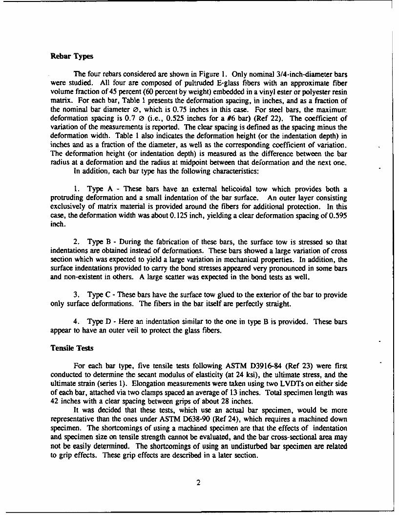
The four rebars considered are shown in Figure I. Only nominal 3/4-inch-diameter barswere studied. All four are composed of pultruded E-glass fibers with an approximate fibervolume fraction of 45 percent (60 percent by weight) embedded in a vinyl ester or polyester resinmatrix. For each bar, Table 1 presents the deformation spacing, in inches, and as a fraction ofthe nominal bar diameter 0, which is 0.75 inches in this case. For steel bars, the maximumdeformation spacing is 0.7 0 (i.e., 0.525 inches for a #6 bar) (Ref 22). The coefficient ofvariation of the measurements is reported. The clear spacing is defined as the spacing minus thedeformation width. Table 1 also indicates the deformation height (or the indentation depth) ininches and as a fraction of the diameter, as well as the corresponding coefficient of variation.The deformation height (or indentation depth) is measured as the difference between the barradius at a deformation and the radius at midpoint between that deformation and the next one.
In addition, each bar type has the following characteristics:
1. Type A - These bars have an external helicoidal tow which provides both aprotruding deformation and a small indentation of the bar surface. An outer layer consistingexclusively of matrix material is provided around the fibers for additional protection. In thiscase, the deformation width was about 0.125 inch, yielding a clear deformation spacing of 0.595inch.
2. Type B - During the fabrication of these bars, the surface tow is stressed so thatindentations are obtained instead of deformations. These bars showed a large variation of crosssection which was expected to yield a large variation in mechanical properties. In addition, thesurface indentations provided to carry the bond stresses appeared very pronounced in some barsand non-existent in others. A large scatter was expected in the bond tests as well.
3. Type C - These bars have the surface tow glued to the exterior of the bar to provideonly surface deformations. The fibers in the bar itself are perfectly straight.
4. Type D - Here an indentation similar to the one in type B is provided. These bars
appear to have an outer veil to protect the glass fibers.
Tensile Tests
For each bar type, five tensile tests following ASTM D3916-84 (Ref 23) were firstconducted to determine the secant modulus of elasticity (at 24 ksi), the ultimate stress, and theultimate strain (series 1). Elongation measurements were taken using two LVDTs on either sideof each bar, attached via two clamps spaced an average of 13 inches. Total specimen length was42 inches with a clear spacing between grips of about 28 inches.
It was decided that these tests, which use an actual bar specimen, would be morerepresentative than the ones under ASTM D638-90 (Ref 24), which requires a machined downspecimen. The shortcomings of using a machined specimen are that the effects of indentationand specimen size on tensile strength cannot be evaluated, and the bar cross-sectional area maynot be easily determined. The shortcomings of using an undisturbed bar specimen are relatedto grip effects. These grip effects are described in a later section.
2
To alleviate these grip effects, three more tensile tests were conducted for Types A andC (series 2). In these tests, specially designed grips consisting of four aluminum blocks boltedtogether were used. Shims consisting of strips from a 3/4-inch annealed aluminum pipe wereinserted between grips and specimens. Only ultimate stresses are reported for this series.
Bond Tests
The objective of these tests was to determine configuration-independent, local bond stress-slip data for use in constitutive material models. Typically, bond stress-slip curves are derivedfrom pullout tests, or other more complex setups, without regard for the lateral confinementexerted by the particular setup. As a result, very disparate curves have been obtained which areonly representative of the particular setup. If the lateral confinement is taken into account, afamily of curves can be obtained, which could be used with any other configuration. Theproposed tests have already been carried out for steel bars (Refs 25 to 27) yielding general bondstress-slip relationships successfully used in predicting a variety of well known results reportedin the literature (Refs 28 to 30).
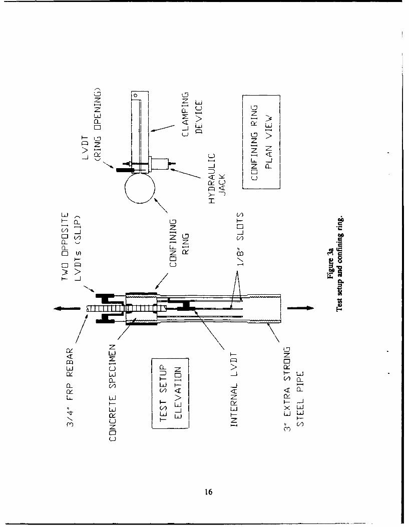
The specimen used is shown in Figure 2. It consists of a 3-inch-diameter, 4-inch-longconcrete cylinder surrounding an FRP rebar. Only 2.625 inches of the bar are actually in contactwith the concrete, with contact being prevented in the rest of the specimen via silicone-rubberspacers. The outer concrete surface is surrounded by a split, threaded steel pipe which carriesthe pullout force via shear stresses (Figure 3). The pipe is split into eight strips in order to offerno lateral resistance. The concrete cylinder is actually cast-in-place against the pipe threads.Casting was carried out with the axis of the specimen placed vertically.
The radial confining pressure on the specimen is applied via a thin ring which surroundsthe portion of pipe containing the concrete cylinder. A hydraulic jack with an adjustable reliefvalve closed the ring with a constant force during the test. In this way the longitudinal reactionand the radial confinement can be both controlled and measured independently of each other.
The concrete mix proportions were 1:3.02:1.35 for cement, sand, and 3/8-inch gravel,respectively. The water-cement ratio was 0.55. Three uniaxial compressive tests at 28 days onthree 6-inch-tall, 3-inch-diameter cylinders yielded an average compressive strength of 4,220 psi.Three tensile splitting tests on the same specimen size yielded a tensile strength of 405 psi.
Bond Tests: Instrumentation and Procedure
On the loaded end of the bar, slip was measured using two LVDTs. They werediametrically opposed to compensate for any rotation. These LVDTs were clamped to the barand measured the relative displacement of the outer concrete surface (i.e., the pipe). A thirdLVDT was located inside the pipe and measured the relative displacement (slip) between the pipeand the unloaded end of the bar. Finally, another LVDT measured the opening of the confiningring. This was later translated into a radial deformation. The apparatus was installed in a MTStesting machine. The MTS load cell provided pullout load measurements from which bondstresses were derived. A pressure gage was used to set the confining pressure.
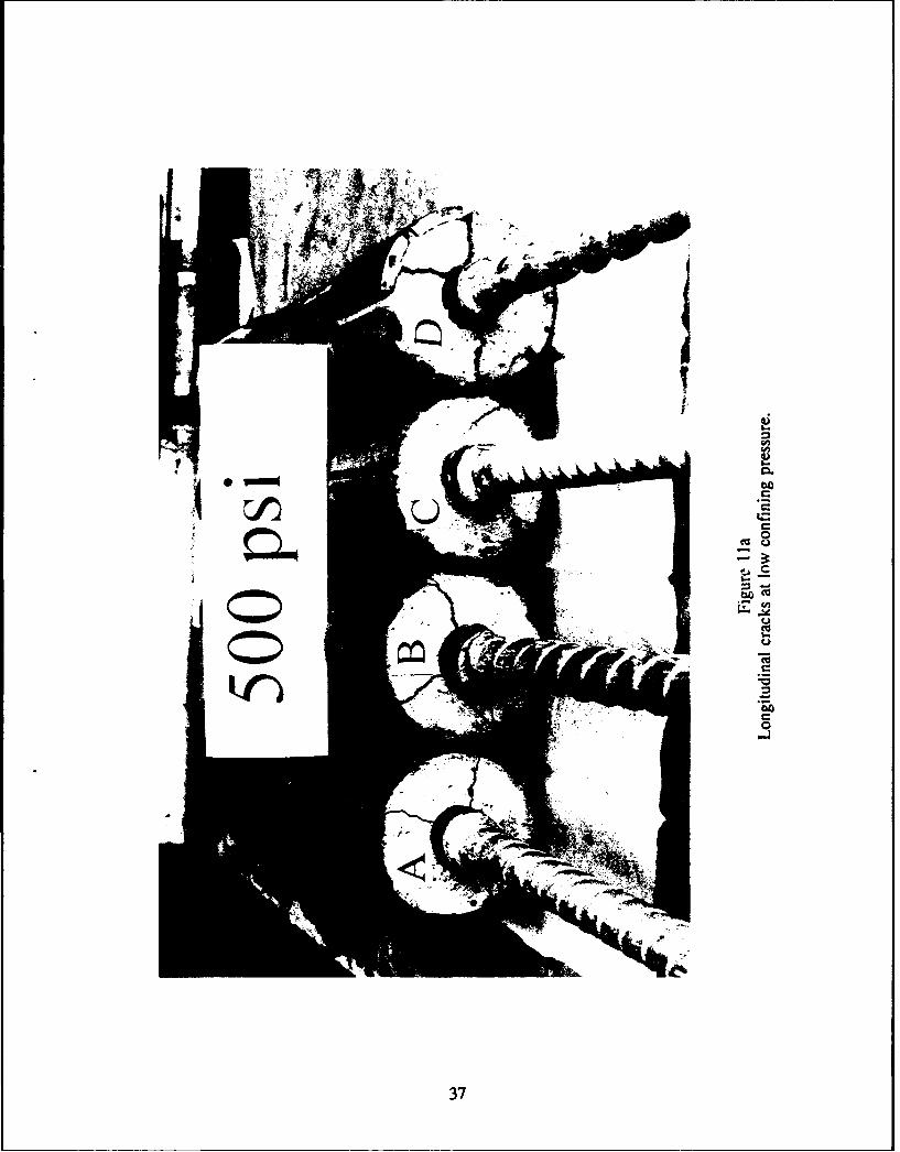
Prior to each test, the concrete cylinder was precracked by setting a bar surface pressureof 500 psi and pulling on the bar until longitudinal splitting would occur. The specimen wasthen unloaded. After cracking, the confining pressure at the bar surface was set at either 500,1,500, 2,500, 3,500, or 4,500 psi and kept constant during the remainder of the test. Aftercracking (and assuming that the cracks are open) all the pressure from the confining ring is
3
transferred to the bar. All tests were carried out in displacement control to obtain the unloadingbranches of the responses.
EXPERIMENTAL RESULTS
Tensile Test Results: Series 1
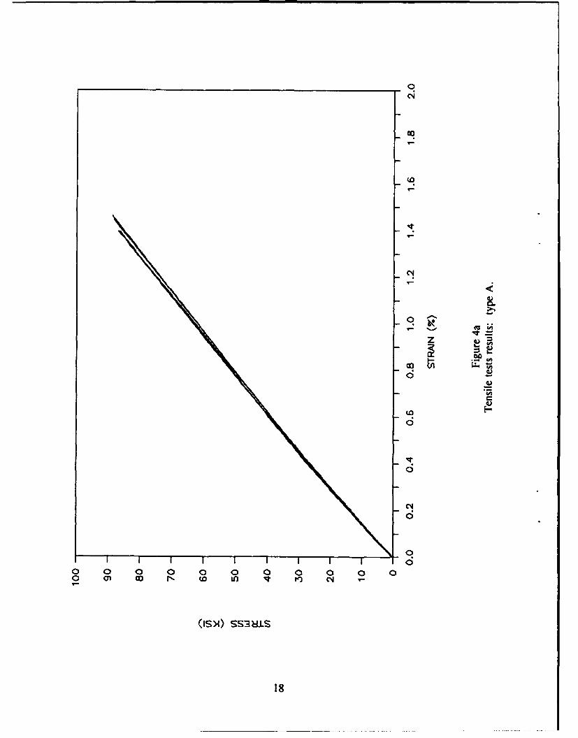
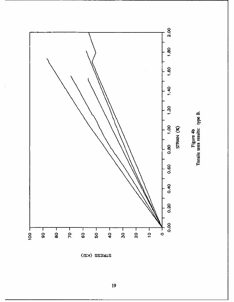
For each bar type, Table 2 shows the average properties obtained. The modulus ofelasticity indicated is the secant modulus at a stress of 24 ksi. Stresses are obtained by dividingultimate loads by the nominal cross section. Values in parenthesis are coefficients of variation.Figure 4 shows the stress-strain relationships for each bar.
It is observed that types A and C had similar moduli of elasticity and ultimate stresses.In addition, for these two types, results for all five bars were very consistent. Bar type D hada slightly lower modulus of elasticity but similar ultimate stress. Bar type B had very largescatter as indicated by the large coefficient of variation, with variations in modulus of elasticityand ultimate stress in excess of 50 percent (see Figure 4b). This was expected given thevariation in cross-sectional area.
For each bar type, the following observations at failure are pertinent:
1. Type A - These bars have an additional layer consisting exclusively of matrixmaterial around the fibers. This layer would tend to separate and initiate the bar failure, usuallyclose to the grips. Subsequent to this separation, the bars could be reloaded to loads close to theultimate. In all five tests, longitudinal splitting of the bar was observed which could be causedby a weak fiber-matrix interface (Ref 31).
2. Type B - The indentations produced sharp kinks in the longitudinal bar fibers. Barfailure was initiated by cracking at the kinks.
3. Type C - During the tests it was observed that the surface tow glued to the barsurface tended to get unbonded. In two cases, failure initiated at the grips. In all tests,longitudinal splitting of the bar was observed. Previous tests on these bars following ASTMD)638-90 (Ref 24) yielded an average ultimate stress of 100 ksi and an elastic modulus of 6.1 Msi(Ref 17). Although this value for the modulus is similar to the present results, the ultimate stressis higher. This can be attributed to the difference in size between test specimens (in the ASTMD638-90 specimen only a 2.25-inch straight section was actually tested), and to the grip effects.
4. Type D - As in type B, bar failure usually initiated at the indentations. Previoustests on two 3/4-inch coupons following ASTM D638-90 were reported to yield ultimate stressesof 77.6 and 84.6 ksi, similar to the current average value (Ref 32).
Tensile Test Results: Series 2
Due to the grip effects encountered for Types A and C, three more tests were conductedfor each one using specially designed grips. These grips had been initially designed for pullingthe bars during the bond tests and are shown in Figure 3b. Results are shown in Table 3.
4
Although failure did still initiate at the grips in most cases, no early cracking or crushingsounds were perceived during the lei ts. Significantly higher ultimate stresses were measured forType C (26 percent higher), which are now very close to the ones reported in Reference 17. ForType A, the increase was small, due again to the premature failure of the additional matrix layer.
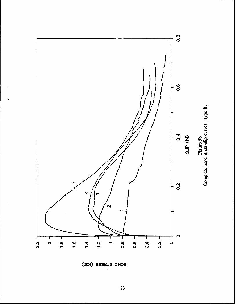
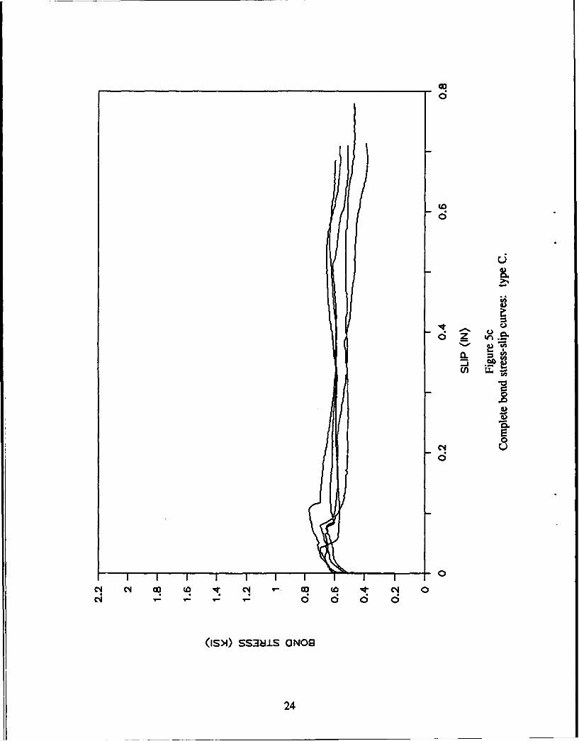
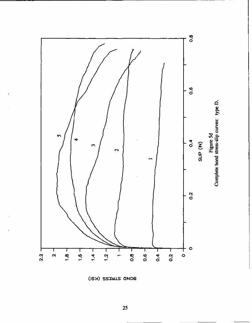
Bond Test Results: Complete Bond Stress-Slip Curves
In the following, tests I through 5 for each bar type correspond to confining pressuresat the bar surface of 500 through 4,500 psi (in 1,000-psi increments), as mentioned earlier. Theslip mentioned in this section is the average measurement of the two LVDTs located on theloaded end of the bar. This measurement was corrected for the unbonded length of rebar andthe gage offset.
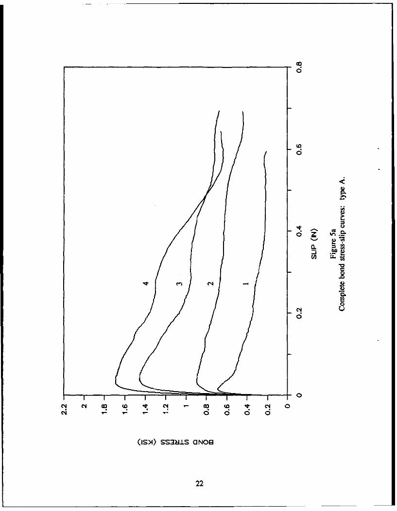
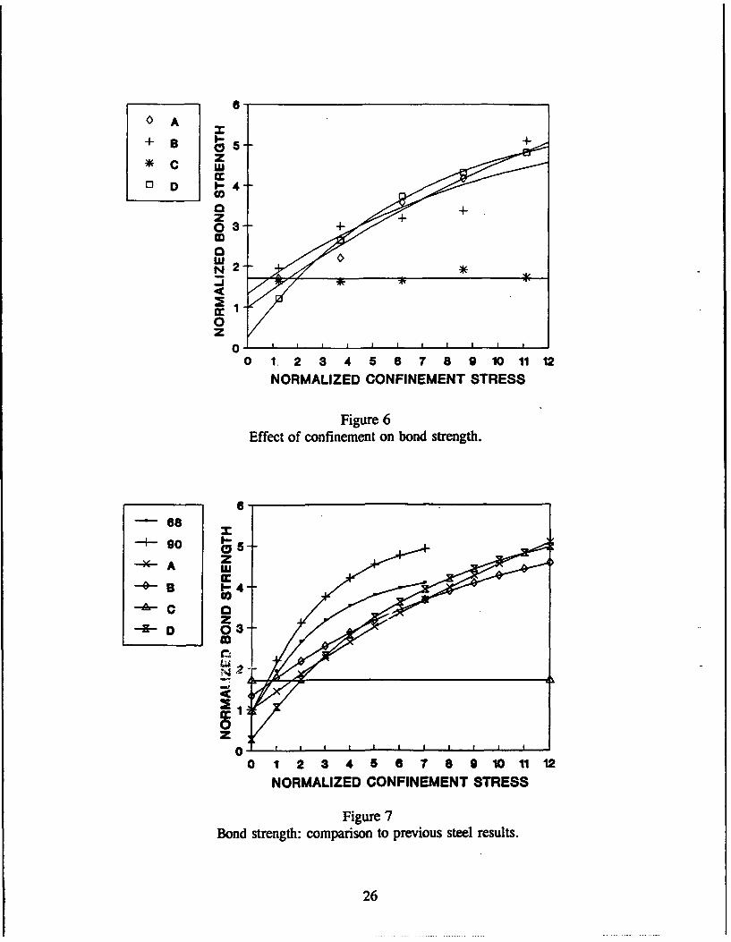
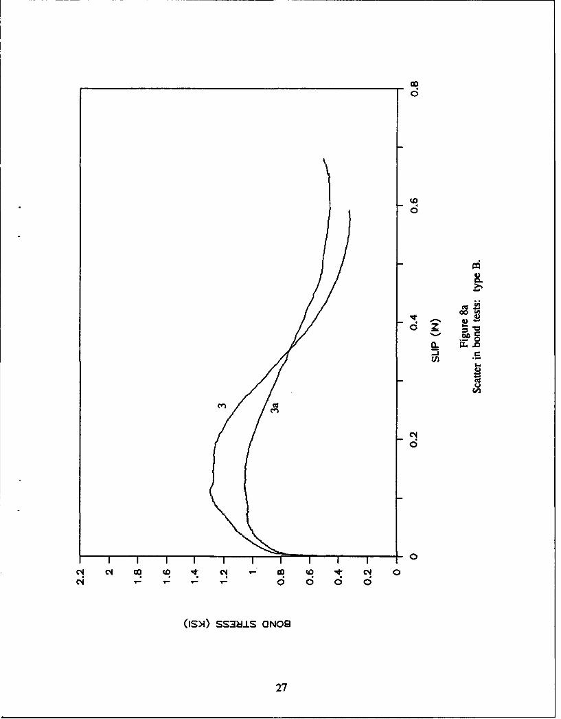
Figure 5 shows the complete bond stress versus loaded-end slip response. Figure 6 showsthe variation in bond strength (i.e., peak bond stress) versus radial confining pressure. Bothvalues are normalized by the tensile strength (405 psi). Figure 7 shows the same data togetherwith previous data for steel bars (Refs 25 through 27) (in this figure the points are only markers,not data points). Figure 8 shows some tests repeated for evaluation of indentation depth effects.The following was observed for each bar type:
1. Type A - In test 5 of type A (missing from Figure 5a), the concrete cylinderappeared weaker and those results were discarded. Although the concrete specimen wassubjected to a confining pressure of 4,500 psi at the bar surface in excess of the uniaxialcompressive strength, in most cases this did not result in crushing (due to the multiaxialconfinement).
It was apparent that the response was qualitatively similar to that of steel (Refs 25 through27). The bond strength increased significantly with confinement. At a slip approximately equalto the clear deformation spacing, the bond stress remained fairly constant.
2. Type B - Although the bond strength also increased with confining pressure, a largescatter was present. For test 5, the bar had much greater indentations, yielding an unexpectedlyhigh bond strength. Also, the peaks occurred at a variety of different slip magnitudes.
3. Type C - In these tests the concrete cylinder never split, so most of the confiningpressure was carried by the concrete cylinder as hoop stress. Consequently, the response wasalmost not affected by confinement. The response exhibited a high initial adhesion followed bya constant bond stress for all five tests.
It was observed that the deformations initially glued to the bar debonded during the test.Consequently, the bond stress was dependent on the friction between the bar and the concrete(i.e., on the roughness of the sand coating). This would explain why Reference 16 reports: (1)a high increase in pullout load when the sand coating is present, and (2) no significant increasewhen the deformations pitch is reduced. However, in Reference 16, the deformations may nothave debonded since the shape of the reported pullout load-slip curve indicates deformationlocking, and the bond stresses reported are higher. In any case, the bond response is dependenton the adhesion between the deformations and the bar, and the capacity of this adhesion is noteasily determined.
5

4. Type D - The bond strength increase with confinement was smooth. A sudden dropin bond stress was observed at about 3/4 inch.
5. Confinement Effects on Bond Strength - Figure 6 shows that for types A, B, and Dthe bond strength can be significantly affected by the bar confinement. For type D, the bondstrength increased fourfold when the radial pressure on the bar was increased from 500 to 4,500psi. For types A and B, the increase was closer to threefold.
Figure 7 compares these results with previous data obtained for steel rebars (Refs 25through 27). It is seen that the maximum normalized bond strengths obtained were similar inmagnitude (between 4 and 5) although they were obtained at higher confinement values. For agiven confinement, the bond strength developed by a steel bar was between 1.2 and 1.5 timeshigher than that of the equivalent FRP bar.
6. Effect of Indentation Depth - Two additional tests for types B and D were run as ameans of evaluating the effects of indentation depth on the results.
For type B, a bar was chosen among the ones with shallowest indentations. For this bar,the indentation depth was only 0.022 inch. This test (test 3a) was carried out at a confinementof 2,500 psi to compare with test 3 where the bar had an average indentation depth of 0.057inch (test 5 indentation depth was 0.088 inch). Figure 8a shows that the decrease in indentationdepth is accompanied by a bond strength decrease of 18.4 percent.
Similarly for type D, a second test (test 2a) was carried out at a confinement of 1,500 psi.The bar in test 2a had an indentation depth of 0.051 inch versus 0.071 inch for test 2. Figure8b shows a corresponding decrease in bond strength of 16.2 percent.
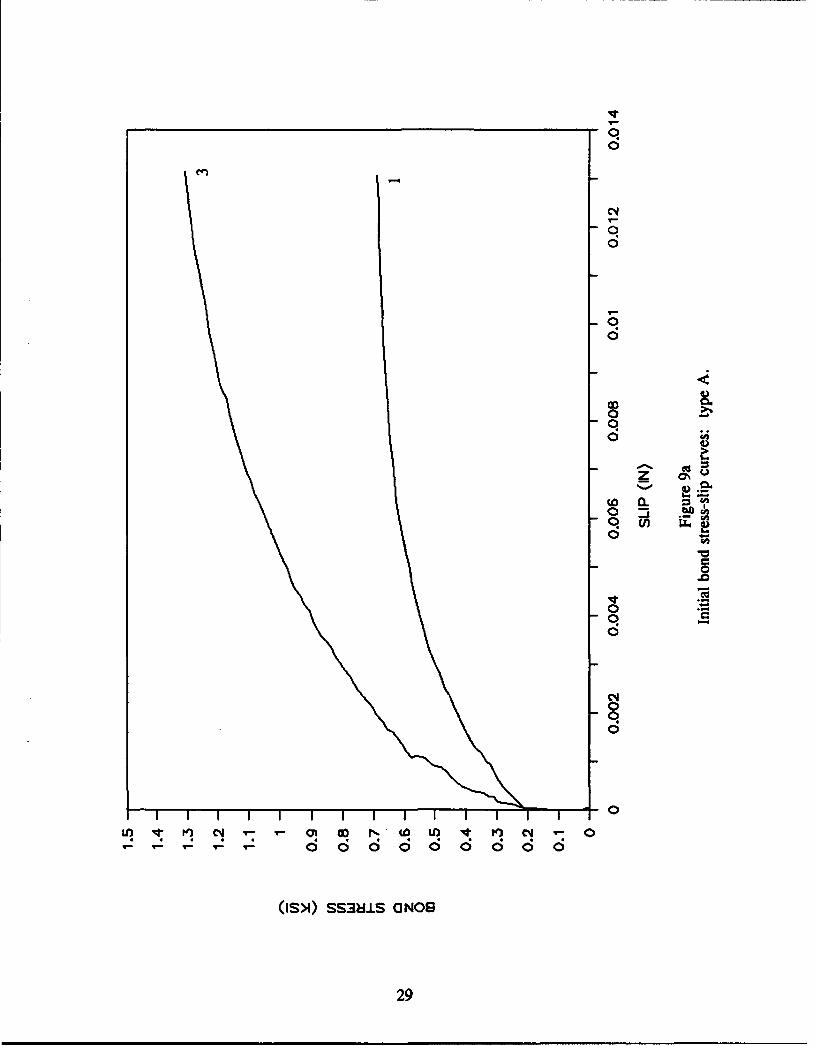
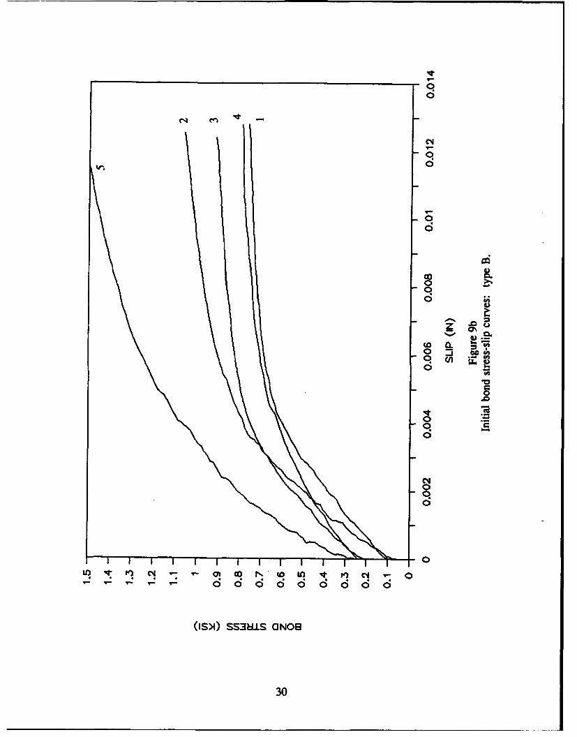
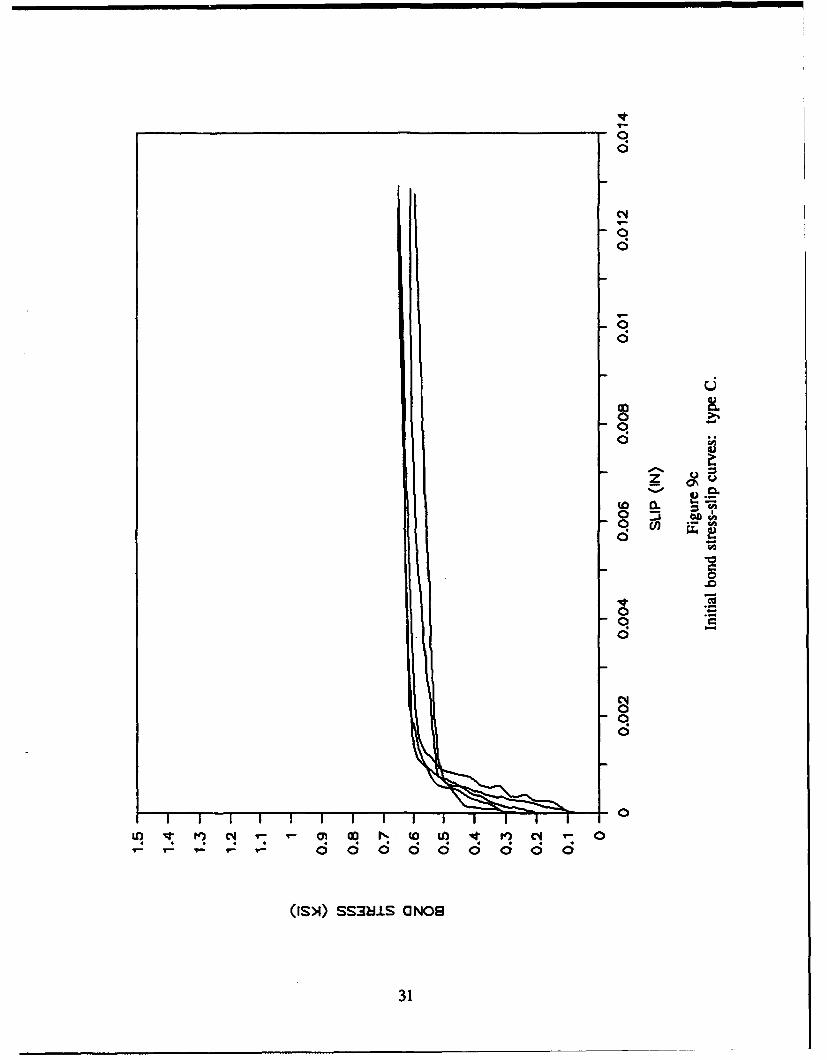
Bond Test Results: Initial Bond Stress-Slip Curves
Upon starting the loading, the two LVDTs on the loaded end of the rebar startedmeasuring displacement, however, the internal LVDT on the unloaded end did not record anymovement for some time. During this initial phase, the slip was nonuniform within the five-lugtest section of the rebar. This was in contrast with the end of the test where all th-ee LVDTsrecorded almost equal slips. References 29 and 30 show the evolution of the slip distributionalong the test length. For the beginning of the loading it indicates that the average slip withinthe test length is approximately equal to:
Average initial slip = (2s 2 + s, )/3
where s1 - average slip from two loaded end LVDTss2= slip from unloaded end (internal) LVDT
Figure 9 shows the initial bond stress-slip curves using the average initial slip defined.The following observations are pertinent:
"* All curves show some adhesion between 100 and 300 psi (i.e., a bond stress at zeroslip).
"* Beyond this adhesion, the slope of the curve appears to increase with higherconfinement.
6
Bond Test Results: Bond Stress-Radial Displacement Curves
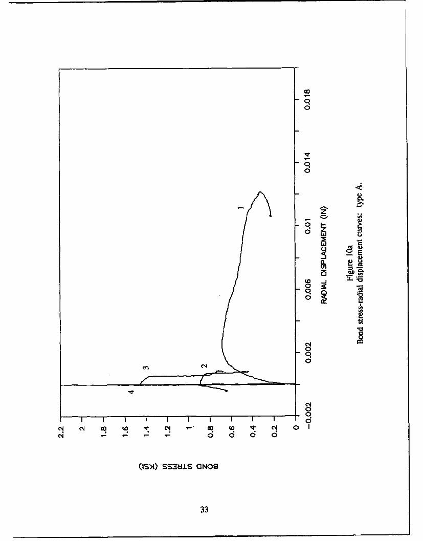
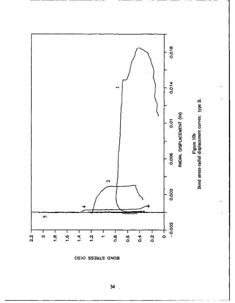
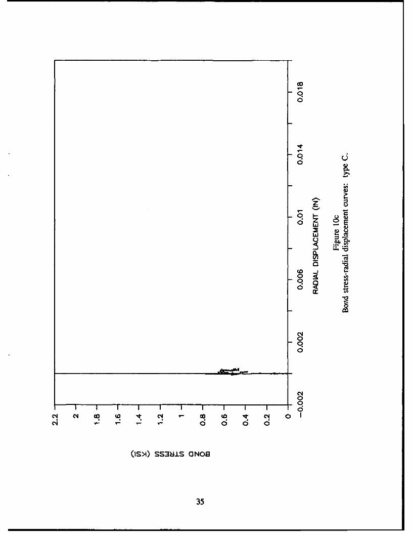
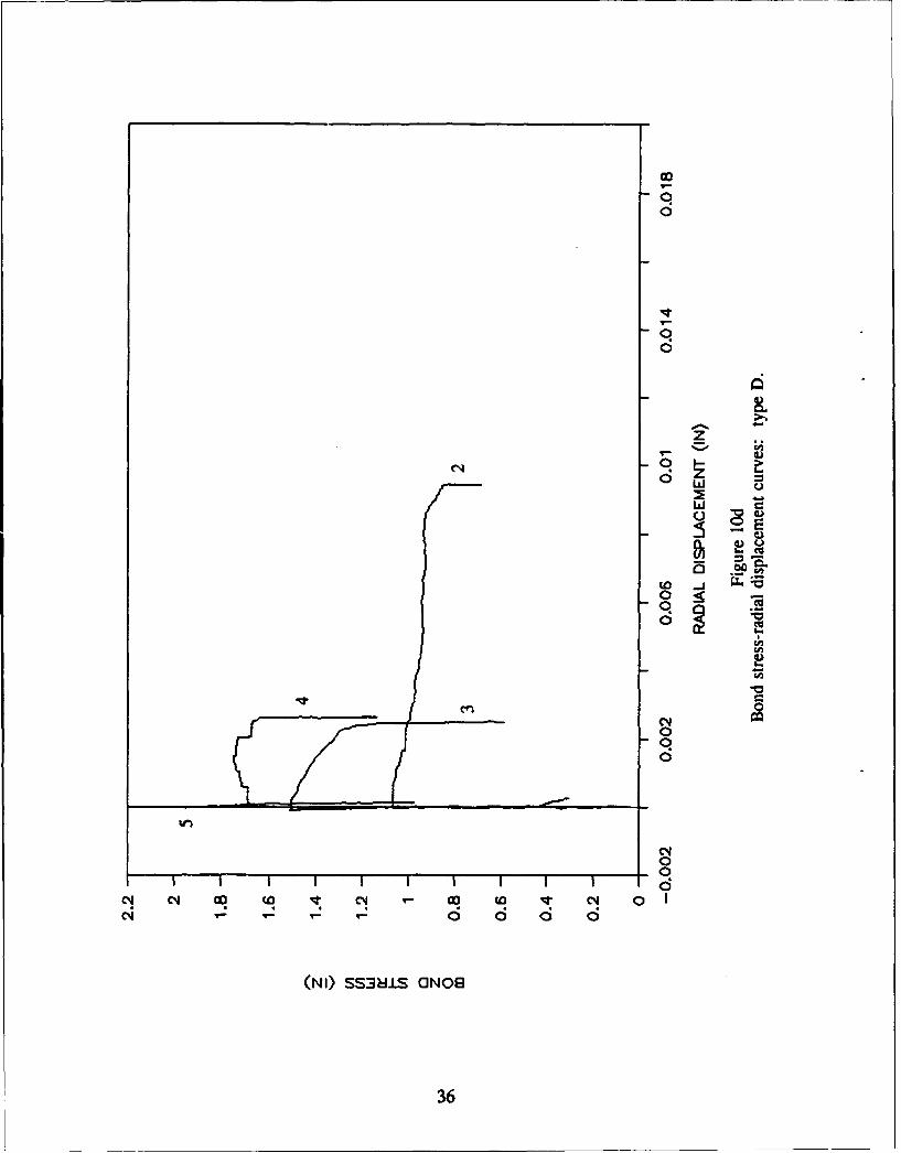
Upon first loading, the rebar deformations exert radial pressures against the surroundingconcrete until the latter splits longitudinally. If external confinement is provided (as in thepresent case), the rebars tend to slowly open the concrete cracks until enough space is createdfor the lugs to advance, via a combination of sliding and concrete crushing. Eventually, afterenough crushing has taken place, a radial contraction may occur (Refs 25 through 27). Tocapture this dilation, the ring opening was measured, which was converted to a radialdisplacement at the outer surface of the concrete cylinder specimen. The bond stress versusradial displacement curves obtained are shown in Figure 10.
For each rebar type the following was observed:
1. Type A - A standard response, similar to that of steel (Ref 25), was obtained, whereradial dilation took place, mainly past the peak stress, then a fairly constant maximum openingwas reached, and was usually followed by a contraction. The contraction was most visible intest 1, whereas the constant maximum opening was more obvious in tests 2 and 3. In test 4, theexternal pressure was high enough to prevent any dilation and allow only for some contractionat the end of the test. The maximum dilation reached decreased rapidly with increasingconfining pressure.
2. Type B - A similar response was obtained. Larger dilation was obtained due to thepresence of large indentation depths.
3. Type C - No dilation was apparent, consistent with the fact that the concrete cylindersnever split.
4. Type D - No contraction was apparent at the end of the tests probably due to the factthat the final slip was much smaller than the indentation spacing for this bar type. Some scatterwas present as shown by the fact that test 3 had a greater maximum dilation that test 2. Nodilation was present for the higher confining pressures.
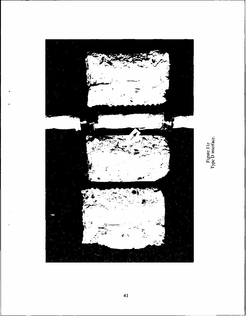
Bond Test Results: Interface Examination
In all specimens (except type C), three or more evenly spaced longitudinal cracks wouldform during the first loading cycle. At low confining pressures, there were usually three cracks,and large crack openings would be present at the end of the test (Figure 1 la). At high confiningpressures, four to six longitudinal cracks would form, with smaller openings. The specimenswere consequently opened to observe the interface condition. The first observation was theabsence of radial cracks which are significant in the case of steel bars (Refs 25 through 27).For each bar type, the following was also noted:
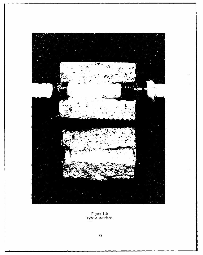
1. Type A - Figure 1 lb shows that the concrete at the indentations was crushed and theresin cover between indentations suffered significant damage. The underlying fibers appearedto have been protected.
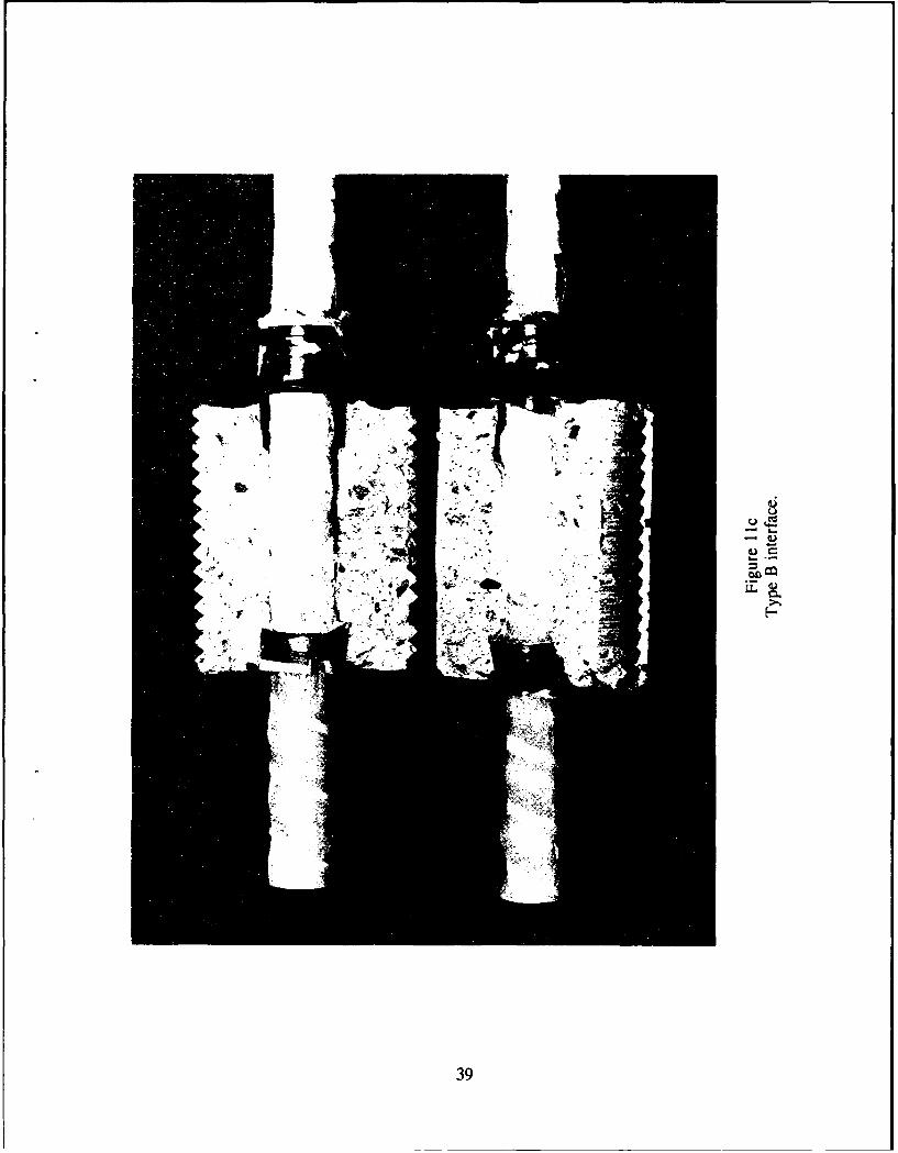
2. Type B - Figure 1 ic shows similar results although fibers between indentations were
sheared off.
7
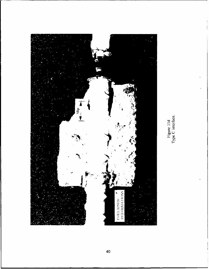
3. Type C - For this rebar type, the specimens did not crack longitudinally during thetests, but they were cracked into two pieces a posteriori to observe the interface.
In Figure lId it can be seen that the deformations fractured near the loaded end. Thelongitudinal distance between both sides of the fracture is equal to the final slip. Both thedeformations and the sand coating within the concrete cylinder remained perfectly bonded to theconcrete and separated from the longitudinal fibers. The other side of the fractured deformationmoved out with the bar. At the unloaded end of the specimen, all the deformations which shouldhave advanced collapsed together. This failure mechanism took place in all specimens of thistype.
4. Type D - Figure I le shows that the protective veil was separated from the rest of thebar. This was apparent in two specimens.
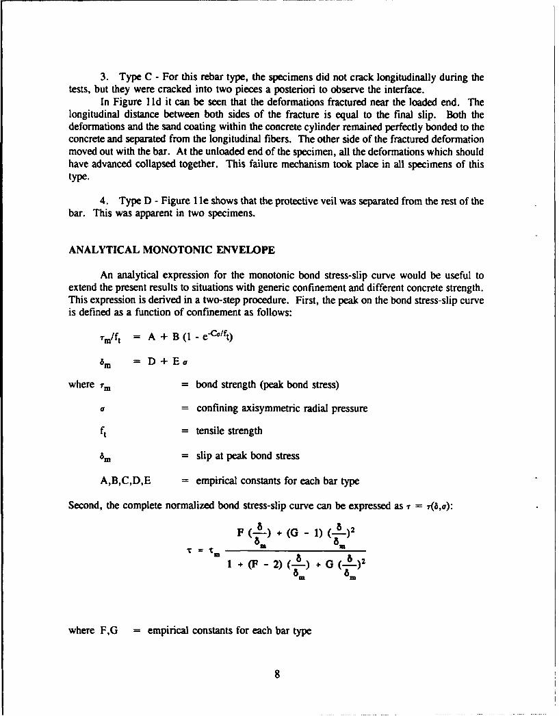
ANALYTICAL MONOTONIC ENVELOPE
An analytical expression for the monotonic bond stress-slip curve would be useful toextend the present results to situations with generic confinement and different concrete strength.This expression is derived in a two-step procedure. First, the peak on the bond stress-slip curveis defined as a function of confinement as follows:
.-m/ft = A + B(1 -e-'/ft)
am = D+Ea
where 7m = bond strength (peak bond stress)
a = confining axisymmetric radial pressure
ft = tensile strength
am = slip at peak bond stress
A,B,C,D,E = empirical constants for each bar type
Second, the complete normalized bond stress-slip curve can be expressed as 7 =(,0):
F (-) (G- 1) (-8)2
1 + (]p- 2) +) G 6)2wam tm
where F,G =empirical constants for each bar type
8
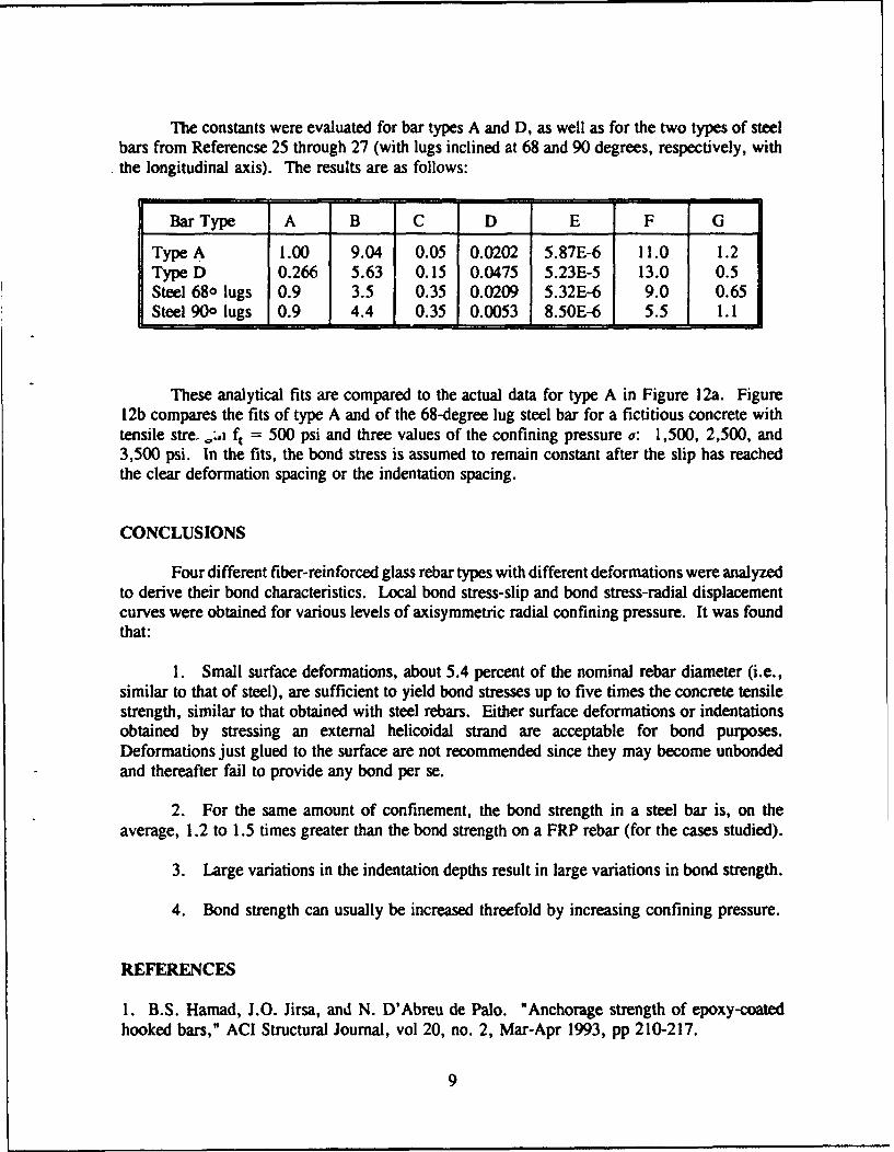
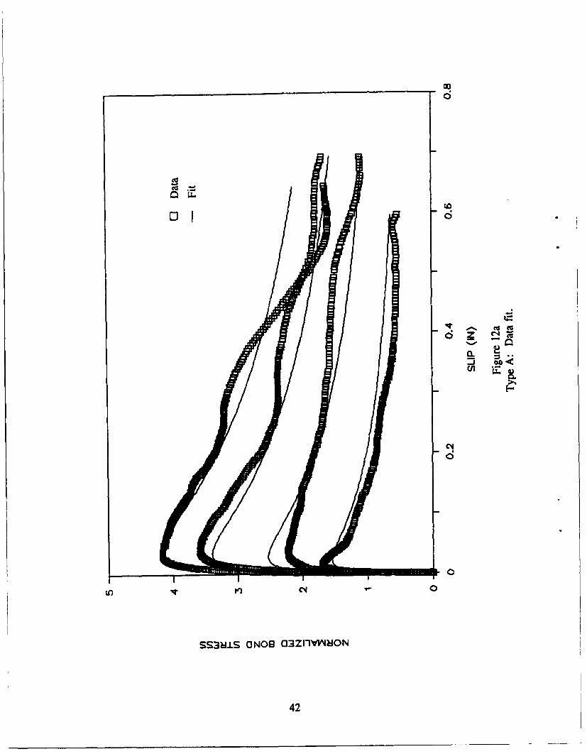
The constants were evaluated for bar types A and D, as well as for the two types of steelbars from Referencse 25 through 27 (with lugs inclined at 68 and 90 degrees, respectively, withthe longitudinal axis). The results are as follows:
=
Bar Type A B C D E F G
Type A 1.00 9.04 0.05 0.0202 5.87E-6 11.0 1.2Type D 0.266 5.63 0.15 0.0475 5.23E-5 13.0 0.5Steel 680 lugs 0.9 3.5 0.35 0.0209 5.32E-6 9.0 0.65Steel 900 lugs 0.9 4.4 0.35 0.0053 8.50E-6 5.5 1.1
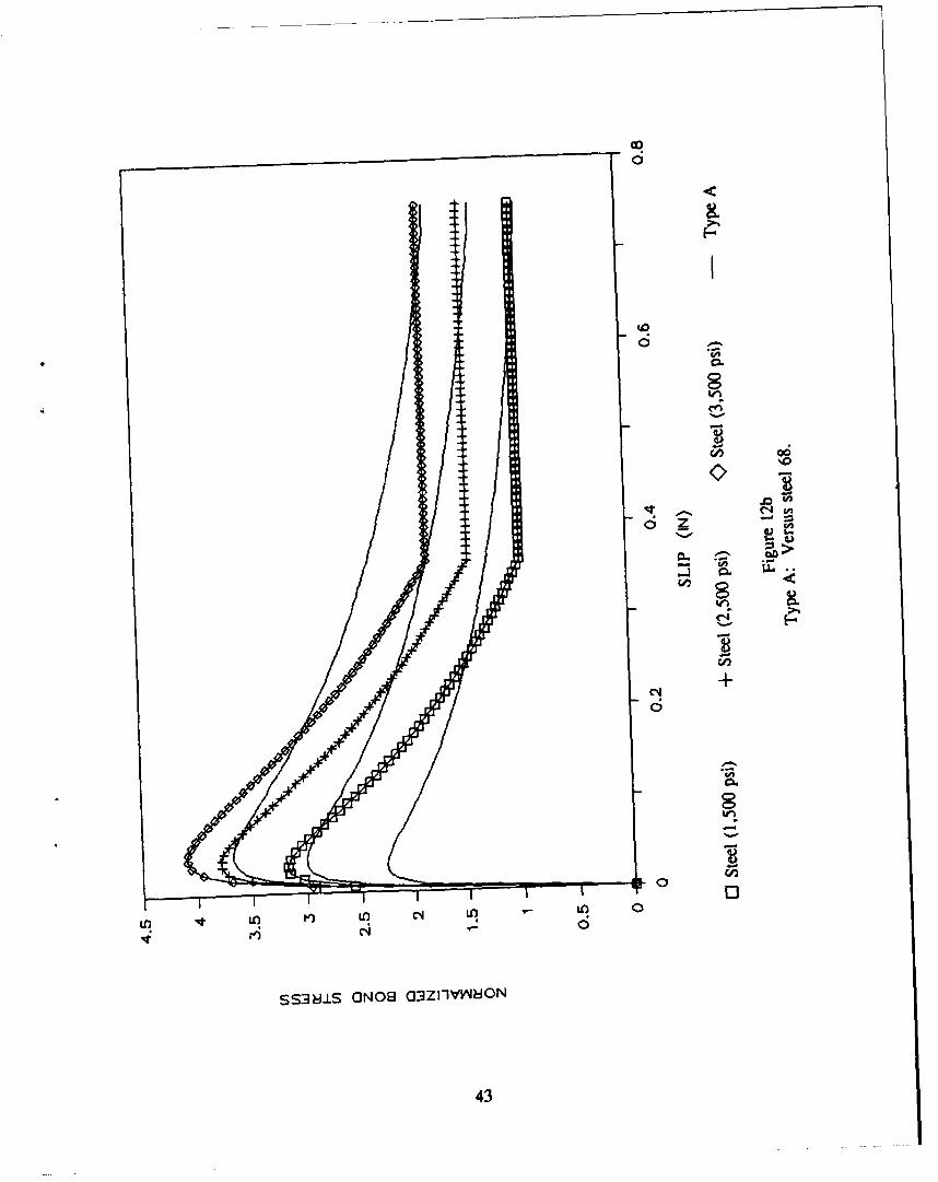
These analytical fits are compared to the actual data for type A in Figure 12a. Figure12b compares the fits of type A and of the 68-degree lug steel bar for a fictitious concrete withtensile stre. o,:i ft = 500 psi and three values of the confining pressure a: 1,500, 2,500, and3,500 psi. In the fits, the bond stress is assumed to remain constant after the slip has reachedthe clear deformation spacing or the indentation spacing.
CONCLUSIONS
Four different fiber-reinforced glass rebar types with different deformations were analyzedto derive their bond characteristics. Local bond stress-slip and bond stress-radial displacementcurves were obtained for various levels of axisymmetric radial confining pressure. It was foundthat:
1. Small surface deformations, about 5.4 percent of the nominal rebar diameter (i.e.,similar to that of steel), are sufficient to yield bond stresses up to five times the concrete tensilestrength, similar to that obtained with steel rebars. Either surface deformations or indentationsobtained by stressing an external helicoidal strand are acceptable for bond purposes.Deformations just glued to the surface are not recommended since they may become unbondedand thereafter fail to provide any bond per se.
2. For the same amount of confinement, the bond strength in a steel bar is, on theaverage, 1.2 to 1.5 times greater than the bond strength on a FRP rebar (for the cases studied).
3. Large variations in the indentation depths result in large variations in bond strength.
4. Bond strength can usually be increased threefold by increasing confining pressure.
REFERENCES
1. B.S. Hamad, J.O. Jirsa, and N. D'Abreu de Palo. "Anchorage strength of epoxy-coatedhooked bars," ACI Structural Journal, vol 20, no. 2, Mar-Apr 1993, pp 210-217.
9

2. D.P. Gustafson. "Epoxy update," Civil Engineering, ASCE, vol 58, no. 10, Oct 1988,pp 38-41.
3. D. Darwin, S.L. McCabe, H. Hadje-Ghaffari, and O.C. Choi. "Bond strength of epoxy-coated reinforcement to concrete - An update," Serviceability and Durability in ConstructionMaterials, in Proceedings of the First Materials Engineering Congress, Denver, CO, Aug 1990,pp 115-124.
4. University of Kansas Center for Research. SM Report No. 28: Effects of epoxy-coatingon the bond of reinforcing steel to concrete, by H. Hadje-Ghaffari, D. Darwin, and S. McCabe.Lawrence, KS, Jul 1991.
5. C.A. Ballinger. "Development of composites for civil engineering," in Proceedings of theConference on Advanced Composite Materials in Civil Engineering Structures, ASCE, LasVegas, NV, 1991, pp 288-301.
6. H. Saadatmanesh and M.R. Ehsani. "Application of fiber-composites in civil engineering,"Structural Materials, in Proceedings of the Structures Congress 1989, ASCE, San Francisco, CA(J.F. Orofino, ed.), May 1989, pp 526-535.
7. R. Sen, S. lyer, M. Issa, and M. Shahawy. "Fiberglass pretensioned piles for marineenvironment," in Proceedings of the Conference on Advanced Composite Materials in CivilEngineering Structures, ASCE, Las Vegas, NV, 1991, pp 348-359.
8. R. Wolff and H.J. Miesseler. "New materials for prestressing and monitoring heavystructures," Concrete International, vol 11, no. 9, Sep 1989, pp 86-89.
9. C.W. Dolan. "Developments in non-metallic prestressing tendons," PCI Journal, Sep-Oct1990, pp 80-88.
10. H.J. Miesseler and R. Wolff. "Experience with fiber composite materials and monitoringwith optical fiber sensors," in Proceedings of the Conference on Advanced Composite Materialsin Civil Engineering Structures, ASCE, Las Vegas, NV, 1991, pp 167-181.
11. C.H. Goodspeed, G. Aleva, and E. Shmeckpeper. "Bridge deck test facility for FRPreinforced bridge deck panels," Use of Composite Materials in Transportation Systems, AMD-vol 129, Winter Annual Meeting, ASME, pp 73-76.
12. J. Larralde and R. Siva. "Bond stress-slip relationships of FRP rebars in concrete,"Serviceability and Durability in Construction Materials, in Proceedings of the First MaterialsEngineering Congress, Denver, CO, Aug 1990, pp 1134-1141.
13. S. Iyer and M. Anigol. "Testing and evaluating fiberglass, graphite, and steel prestressingcables for pretensioned beams," in Proceedings of the Conference on Advanced CompositeMaterials in Civil Engineering Structures, ASCE, Las Vegas, NV, 1991, pp 44-56.
10

14. L.G. Pleimann. "Strength, modulus of elasticity, and bond of deformed FRP rods," inProceedings of the Conference on Advanced Composite Materials in Civil EngineeringStructures, ASCE, Las Vegas, NV, 1991, pp 99-110.
15. S. Tao, M.R. Ehsani, and H. Saadatmanesh. "Bond strength of straight GFRP rebars,"Materials Performance and Prevention of Deficiencies and Failures, in Proceedings of theMaterials Engineering Congress, ASCE, Atlanta, GA, 1992, pp 598-605.
16. 0. Challal and B. Benmokrane. "Pullout and bond of glass-fibre rods embedded in concreteand cement grout," Materials and Structures, vol 26, Apr 1993, pp 167-175.
17. 0. Challal and B. Benmokrane. "Glass-fiber reinforcing rod: Characterization andapplication to concrete structures and grouted anchors," Materials Performance and Preventionof Deficiencies and Failures, in Proceedings of the Materials Engineering Congress, ASCE,Atlanta, GA, 1992, pp 606-617.
18. 0. Challal, B. Benmokrane, and R. Masmoudi. "An innovative glass-fire composite rebarfor concrete structures," Advanced Composite Materials in Bridges and Structures, FirstInternational Conference, Sherbrooke, Quebec, Canada, 1992, pp 169-177.
19. S. Daniali. "Development length for fibre-reinforced plastic bars," Advanced CompositeMaterials in Bridges and Structures, First International Conference, Sherbrooke, Quebec,Canada, 1992, pp 179-188.
20. C. Ballinger. "Structural FRP composites," Civil Engineering, ASCE, vol 60, no. 7,Jul 1990, pp 63-65.
21. P. Tarricone. "Plastic potential," Civil Engineering, vol 63, no. 8, Aug 1993, pp 62-63.
22. American Society for Testing and Materials. ASTM A615-89: Standard specification fordeformed and plain billet-steel bars for concrete reinforcement, Annual Book of ASTMStandards, vol 01.04, 1990.
23. ASTM D3916-84: Test method for tensile properties of pultruded glass-fiber-reinforced plastic rod, Annual Book of ASTM Standards, vol 08.03, 1991.
24. ASTM D638-90: Test method for tensile properties of plastics, AnnualBook of ASTM Standards, vol 08.01, 1991.
25. L.J. Malvar. "Confinement stress dependent bond behavior, Part I: Experimentalinvestigation," Bond in Concrete, in Proceedings of the International Conference, Riga, Latvia,Oct 1992, pp 1/79-1/88.
26. L.J. Malvar. "Bond of reinforcement under controlled confinement," ACI MaterialsJournal, vol 89, no.6, Nov-Dec 1992, pp 593-601.
11
27. L.J. Malvar. "Bond of reinforcement under controlled radial pressure," Studi e Ricerche,vol 13-1992, Structural Engineering Department, Polytechnic University of Milan, Milan, Italy,1992, pp 83-118.
28. J.V. Cox and L.R. Herrmann. "A plasticity model for the bond between matrix andreinforcement," in Proceedings of the 6th U.S.-Japan Conference on Composite Materials,Orlando, FL, Jun 1992.
29. J.V. Cox and L.R. Herrmann. "Confinement stress dependent bond behavior, Part II: Atwo degree of freedom plasticity model," Bond in Concrete, in Proceedings of the InternationalConference, Riga, Latvia, Oct 1992, pp 11/11-11/20.
30. J.V. Cox. Development of a plasticity bond model for reinforced concrete - theory andvalidation for monitonic applications, Ph.D. thesis, University of California, Davis, CA, 1994(in preparation).
31. S.H. Saidpour. The effect of fibre/matrix interfacial interactions on the mechanicalproperties of unidirectional E-glass reinforced vinyl ester composites, Ph.D. thesis,Loughborough University of Technology, U.K., 1991.
32. DNV Industrial Services. Tensile test results on nominal 3/4-inch FRP rebar. Houston,TX, 1988.
12
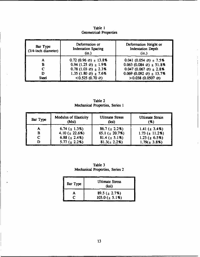
Table 1Geometrical Properties
Bar Type Deformation or Deformation Height orIndentation Spacing Indentation Depth(3/4-inch diameter)(n)(i.
(in.) (in.)
A 0.72 (0.96 0) + 13.8% 0.041 (0.054 0) + 7.5%B 0.94 (1.25 0) + 1.9% 0.063 (0.084 0) + 51.8%C 0.78 (1.03 0) + 2.3% 0.047 (0.067 0) + 2.8%D 1.35 (1.80 0) + 7.6% 0.069 (0.092 0) + 13.7%
Steel <0.525 (0.70 0) >0.038 (0.0507 0)
Table 2Mechanical Properties, Series 1
Bar Type Modulus of Elasticity Ulitmate Stress Ultimate Strain(Msi) (ksi) (%)
A 6.74 (± 1.3%) 86.7 (± 2.2%) 1.41 (± 3.4%)B 4.10 (± 22.6%) 65.1 (+ 20.7%) 1.73 (± 11.2%)C 6.88 (± 2.4%) 81.4 (+ 5.1%) 1.23 (± 6.5%)D 5.77 (± 2.2%) 81.3(± 2.2%) 1.79(± 3.8%)
Table 3Mechanical Properties, Series 2
SBar Type Ultimate StressBar Typ(ksi)
A 89.5 (± 2.7%)C 103.0(± 5.1%)
13

Figure I
Bar types.
14

H-
LJJ
-LJOCL a-
t
L-j
LiJIL a
-H
LI
-J
4Z r:
La:L
<1 I-
-4 'q~j\>(
NL
I___ V)
< z cjý15
_ L~I ma-i r
_ zi___ t_____
0~ lii I CLP:42
LA-J
LLC.
f--
Y7INN
4x I- z
uLJ IZI
NI~~ X~iiI LdL~
w ___I - (A
16
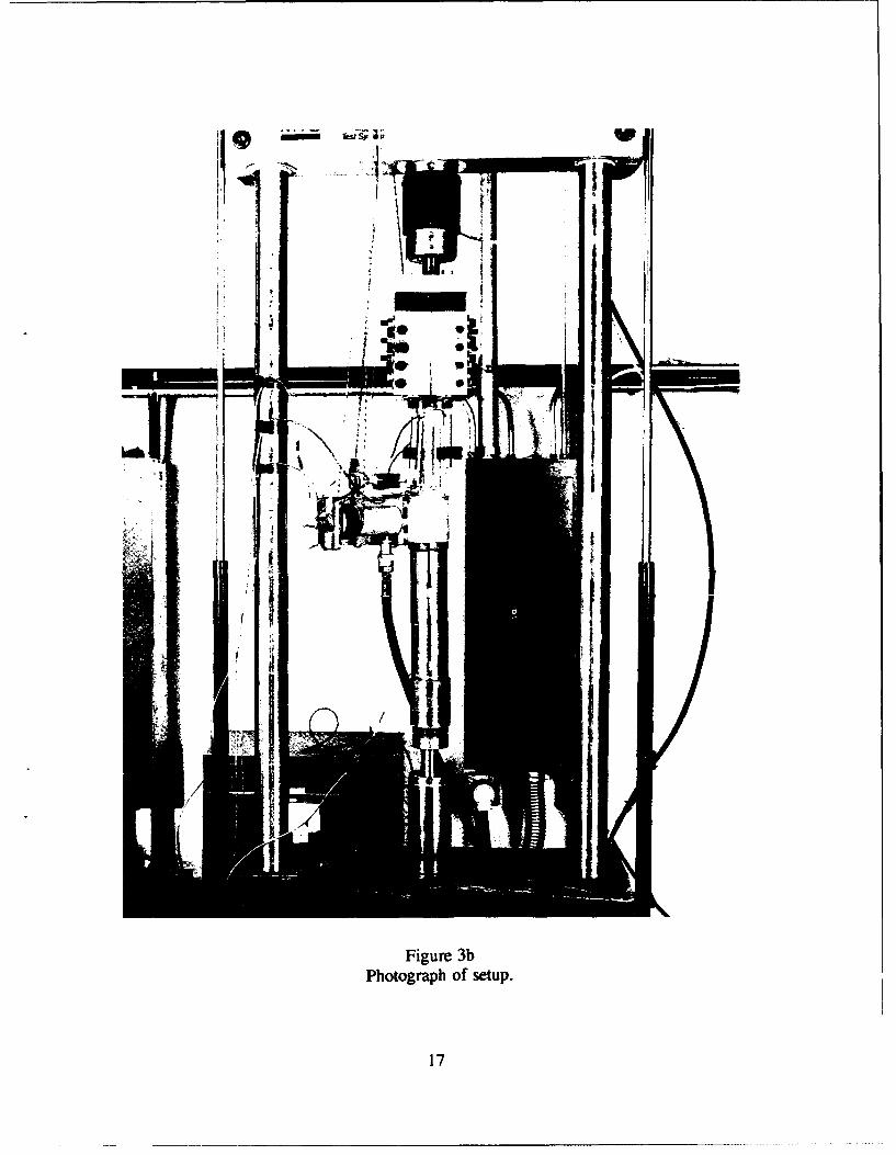
Figure 3bPhotograph of setup.
17
0
oo
(0
c•I
6
T--)
Cqj
0
6
o 0 0 00 0 0 0 0 0 0l ot o o LO to N0 0Q1 • (0r, U, • I') Cl t-
(Is>) ss'8LS
18
c�4
0
0
01�1�
0
V.
Z Ow,
d 4)
4)od
01*0
0C�Jd
0 � 0��
19

C14
0.
0 0ao N ) 14, e) C
OSA) S3ýU
206

z~.S.0
CO (D U) Iq te) )
211
ao
d
0.
(ISA)U SS3IS -O
220
C L C
6O 4
0
0.
CO))
T--oOR C'4 Ci aq 1ý 't o Ci
(zSAO SS31US O NOS
:23
0.
(0
24)
0
N 04 D (D v N 0 to t V
C4)
252
6
0 A .+ 13 (D5-"
wzC0• D '-4
Goz+
0w0N 2 -
0z
0 1. 2 3 4 5 6 7 8 9 10 11 12
NORMALIZED CONFINEMENT STRESS
Figure 6Effect of confinement on bond strength.
-go
z-- A •.Zw
C az
D 03-
0z
0 1 2 3 4 5 6 7 8 9 10 11 12
NORMALIZED CONFINEMENT STRESS
Figure 7Bond strength: comparison to previous steel results.
26
t4,1
Co
00
C. 1: TI 0 0 - m • •
(ISM) SS3MJS (INOS
27

coo
75)
V)
Cuq(%46
Cq4 Cq w 0 ' Cq a- (0 1 CqC4 1: 6 6 6 0
(ISA) SS3N.S O NOS
28
V-
60
0.
0 w
299
7-
V-
9
0
0
Z ci
to0 ch
00
og
OSA) S3M.L CNC
300
-o6
Cl
06
6
oo
(0 0. �
o j
ow *L�
6
0.0
o -
90
Cl090
-o
£0 1 Cl - (0(0 . Cl '-0* ' '- * 000000000
(Is�) SS�1S ONOB
31

Cl4
q0
0
14.1
0o9o
0
'-
00
(ISA)SS3M.S aN-
o32
900
0
z
Lii
w
0 4
00h
(ISA)SS3111S l NO
330
04
0
34-
00
*1-1
0
I-I
355
0
LU u
MUo Va.
C UC.
04 N 0 (0 V N c (0v N
C4 1- 1.: 6 6
(NI)ss:m-Ls0N•
36-
CA
Ca
37
-7! -
Figure I IbType A interface.
38
39
C)V C)
-. -
I--
F-
40
vF-
41
oCo
040
LA) C4
ssmi1s ONOB C33Zf-lV"ON
42
C4 t,
S~~~, S3OtSCIO 3ZII"O
43,

DISTRIBUTION LIST
ADINA ENGRG, INC / WALCZAK, WATERTOWN, MAAFESC / TECH LIB, TYNDALL AFB, FLAMERICAN CONCRETE / LIB, DETROIT, MIANATECH RESEARCH CORP / RASHID, SAN DIEGO, CAAPTEK / SCHWER, SAN JOSE, CAARMY CECOM R&D TECH LIBRARY / ASNC-ELC-I-T, FORT MONMOUTH, NJARMY CERL / LIB, CHAMPAIGN, ILARMY ENGRG DIST / LIB, SEATTLE, WAARMY ENGRG DIST / LIB, PHILADELPHIA, PAARMY ENGRG DIST / LIB, PORTLAND, ORBATTELLE NEW ENGLAND MARINE RSCH LAB / LIB, DUXBURY, MABECHTEL CIVIL, INC I K. MARK, SAN FRANCISCO, CABEN C GERWICK INC / FOTINOS, SAN FRANCISCO, CABETHLEHEM STEEL CO / ENGRG DEPT, BETHLEHEM, PACAL TECH / SCOTT, PASADENA, CACALTRANS I ZELINSKI, SACRAMENTO, CACASE WESTERN RESERVE UNIV / CE DEPT (PERDIKARIS), CLEVELAND, OHCENTRIC ENGINEERING SYSTEMS INC / TAYLOR, PALO ALTO, CACHALMERS UNIVERSITY OF TECH / TEPFERS, SWEDEN,CLARKSON UNIV / CEE DEPT, POTSDAM, NYCOLLEGE OF ENGINEERING / CE DEPT (AKINMUSURU), SOUTHFIELD, MICOLLEGE OF ENGINEERING / CE DEPT (GRACE), SOUTHFIELD, MICOLORADO SCHOOL OF MINES / DEPT OF ENGRG (CHUNG), GOLDEN, COCORNELL UNIV / CIVIL & ENVIRON ENGRG, ITHACA, NYCORNELL UNIV / LIB, ITHACA, NYCREATIVE PULTRUSIONS INC / SWEET, ALUM BANK, PADELFT UNIVERSITY OF TECH / DE BORST, GA DELFT, THE NETHERLANDSDTIC I ALEXANDRIA, VAELICES, MANUEL / MADRID, SPAINFIBERGLAS / GREENWOOD, GRANVILL, OHFLORIDA INST OF TECH / CE DEPT (KALAJIAN), MELBOURNE, FLGEOCISA / RODRIGUEZ, COSLADA MADRID, SPAINGEORGE WASHINGTON UNIV / ENGRG & APP SCI SCHL (FOX). WASHINGTON, DCGEORGIA INST OF TECH / CE SCHL (KAHN), ATLANTA, GAGEORGIA INST OF TECH / CE SCHL (SWANGER), ATLANTA, GAGEORGIA INST OF TECH / DR. J. DAVID FROST, ATLANTA, GAGEORGIA TECH I CHAMEAU, ATLANTA, GAGERWICK, BEN / SAN FRANCISCO, CAHAN-PADRON ASSOCIATES / DENNIS PADRON, NEW YORK, NYHAYNES & ASSOC / H. HAYNES, PE, OAKLAND, CAHERCULES INC / COURTNEY, WILMINGTON, DEHI DEGENKOLB ASSOC / W. MURDOUGH, SAN FRANCISCO, CAHKS INC I JOOP NAGTEGAAL, PROVIDENCE, RIHUS INC f NAGTEGAAL, PAWTUCKET. RIIMCO REINFORCED PLASTICS INC / LAMONICA, MOORESTOWN, NJJOHN HOPKINS UNIV / CE DEPT. JONES. BALTIMORE, MDKARAGOZIAN & CASE STRUCTURAL ENGRS / CRAWFORD, GLENDALE, CALABORATOIRE CENTRAL DES PONTS ET CHAUSSEES I ROSSI, PARIS CEDEX 15, FRANCELABORATOIRE DE MECANIQUE ET TECHNOLOGIE / BERTHAUD, CACHAN, FRANCELAWRENCE LIVERMORE NATIONAL LAB / WHIRLEY LIVERMORE, CAMARINE CONCRETE STRUCTURES, INC / W.A. INGRAHAM, METAIRIE, LAMICHIGAN TECH UNIV / CO DEPT (HAAS), HOUGHTON. MINAVCOASTSYSCEN / CODE 423, PANAMA CITY. FL
44

NAVFACENGCOM / CODE 04B2 (J. CECILIO), ALEXANDRIA, VANBS / BLDG MAT DIV. MATHEY, GAITHERSBURG, MDNEPTCO / RACZELOWSKI, PAWTUCKET, RINEW ZEALAND CONCRETE RSCH ASSN / LIB, PORIRUA,NORTHWESTERN UNIVERSITY / BAZANT, EVANSTON, ILNSF / STRUC & BLDG SYSTEMS (KP CHONG). WASHINGTON, DCOCNR / CODE IOP4 (KOSTOFF), ARLINGTON, VAOCNR / CODE 1121 (EA SILVA), ARLINGTON, VAOCNR / CODE 1132SM, ARLINGTON, VAOHIO STATE UNIVERSITY / CE DEPT (SIERAKOWSKY), COLUMBUS, OHOREGON STATE UNIV I CE DEPT (HICKS), CORVALLIS, ORPURDUE UNIV / CE SCOL (CHEN), WEST LAFAYETTE, INPURDUE UNIV / CE SCOL (RAMIREZ), WEST LAFAYETTE, INPWC / CODE 123C, SAN DIEGO, CAREICHHOLD CHEMICALS INC / MCCLASKEY, RESEARCH TRIANGLE PARK, NCSD SCHOOL OF MINES AND TECH / IYER, RAPID CITY, SDSPI / BARNO, GRANVILLE, OHSTANFORD UNIV / DIV OF APPLIED MECHANICS, STANFORD, CATUFTS UNIV / SANAYEI, MEDFORD, MAUCSD / SEIBLE, LA JOLLA, CAUNIV OF ARIZONA / EHSANI, TUCSON, AZUNIV OF CALIFORNIA / CE DEPT (FOURNEY), LOS ANGELES, CAUNIV OF CALIFORNIA / CE DEPT (HERRMANN), DAVIS, CAUNIV OF CALIFORNIA / CE DEPT (RAMEY), DAVIS, CAUNIV OF CALIFORNIA / CE DEPT (ROMSTADT), DAVIS, CAUNIV OF CALIFORNIA / CE DEPT (SELNA), LOS ANGELES, CAUNIV OF CALIFORNIA / CE DEPT (WILLIAMSON), BERKELEY, CAUNIV OF CALIFORNIA / MECH ENGR (BAYO), SANTA BARBARA, CAUNIV OF CALIFORNIA I MECH ENGR (MCMEEKING), SANTA BARBARA, CAUNIV OF CALIFORNIA t MECH ENGRG DEPT (KEDWARD), SANTA BARBARA, CAUNIV OF CALIFORNIA / MECH ENGRG DEPT (LECKIE), SANTA BARBARA, CAUNIV OF COLORADO / MECH ENGRG DEPT (FELLIPA), BOULDER, COUNIV OF COLORADO I MECH ENGRG DEPT (WILLAM), BOULDER, COUNIV OF COLORADO / STURE, BOULDER, COUNIV OF HAWAII / MANOA, LIB, HONOLULU, HIUNIV OF ILLINOIS / CE LAB (ABRAMS), URBANA, ILUNIV OF ILLINOIS / CE LAB (PECKNOLD), URBANA, ILUNIV OF ILLINOIS / METZ REF RM, URBANA, ILUNIV OF MARYLAND / CE DEPT, COLLEGE PARK, MDUNIV OF MICHIGAN / CE DEPT (RICHART), ANN ARBOR, MIUNIV OF N CAROLINA / CE DEPT (GUPTA), RALEIGH, NCUNIV OF NEW MEXICO / NMERI, HL SCHREYER, ALBUQUERQUE, NMUNIV OF RHODE ISLAND / CE DEPT (LEE), KINGSTON, RIUNIV OF TEXAS I CONSTRUCTION INDUSTRY INST, AUSTIN, TXUNIV OF TEXAS / ECJ 5.402 (TUCKER), AUSTIN, TXUNIV OF TEXAS / ROESSET, AUSTIN, TXUNIV OF WASHINGTON / CE DEPT (MATTOCK). SEATTLE, WAUNIV OF WYOMING / CE DEPT, LARAMIE, WYUNIV OF WYOMING / SCHMIDT, LARAMIE, WYUSCOE / LAMPO, CHAMPAIGN, ILWEIDLINGER ASSOC / F.S. WONG, LOS ALTOS, CAWISS, JANNEY, ELSTNER, & ASSOC / DW PFEIFER, NORTHBROOK, IL
45