Embed Size (px)
Citation preview

Page 1 of 38
III SEMESTER
B.E. Medical Electronics (ML) Choice Based Credit System (CBCS)
Semester - III
ENGINEERING MATHEMATICS-III (Common to All Branches)
Subject Code : 15MAT31 IA Marks : 20
Number of Lecture
Hours/Week
: 04 Exam Marks : 80
Total Number of
Lecture Hours
: 50 Exam Hours : 03
Credits - 4
Course Objectives: This course will enable the students to
Revised Bloom’s Taxonomy Levels: L1 – Remembering, L2 – Understanding, L3 – Applying,
L4 – Analyzing, L5 – Evaluating, and L6 - Creating
Modules Teaching
Hours
Revised
Bloom’s
Taxonomy
(RBT)Leve
l
Module -1
10 Hours
Module -2
10 Hours
Module -3
10 Hours
Page 2 of 38
Module -4
10 Hours
Module -5
10 Hours
Course Outcomes: After studying this course, students will able to:
Graduate Attributes (as per NBA)
Question Paper Pattern:
The question paper will have TEN questions.
Each full question carry16 marks
There will be TWO full questions (with maximum of FOUR sub questions) from each module.
Each full question will have sub questions covering all the topics under a module.
The students will have to answer FIVE full questions, selecting ONE full question from each module.
Text Books:
Reference Books:
Page 3 of 38
B.E. Medical Electronics (ML)
Choice Based Credit System (CBCS)
Semester - III
ELECTRONIC INSTRUMENTATION AND MEASUREMENTS (Common to EI, BM & ML)
Subject Code : 15 EI/BM/ML 32 IA Marks : 20
Number of Lecture
Hours/Week
: 04 Exam Marks : 80
Total Number of
Lecture Hours
: 50 Exam Hours : 03
Credits - 4
Course Objectives: This course will enable the students to
Impart with the knowledge of generalized measurement systems.
Learn the characteristics of various types of measurement systems and errors in measuring
instruments.
Analyze the circuits for the measurement of Resistance, Capacitance, Inductance, and Frequency.
Impart with the basic concepts of CRO and its usage for the measurement of various parameters.
Understand the concepts of Ammeters, Voltmeter and Multimeters
Understand the importance of Display Devices and Recorders in practical fields
Revised Bloom’s Taxonomy Levels: L1 – Remembering, L2 – Understanding, L3 – Applying,
L4 – Analyzing, L5 – Evaluating, and L6 - Creating
Modules Teaching
Hours
Revised
Bloom’s
Taxonomy
(RBT)Leve
l
Module -1
A).Measurements: introduction, Significance of measurements,
methods of measurements, instruments and measurement systems,
Functions of instruments and measurement systems, Applications of
measurement systems.
Measurement Errors: Introduction Gross errors and systematic
errors, Absolute and relative errors, basic concepts of accuracy,
Precision, Resolution and Significant figures, Measurement error
combinations. (relevant problems)
10 Hours L1,L2
Module -2
A). Ammeters, Voltmeter and Multimeters:
Introduction, DC ammeter principle only, DC voltmeter, Multi-range
voltmeter, Extending voltmeter ranges, Loading, Peak responding and
True RMS voltmeters. (relevant problems)
B). Digital Voltmeters:
Introduction, Ramp type, Dual slope integrating type (V–T),
integrating type (V–F) and Successive approximation type (relevant
problems).
10 Hours L1,L2,L3,
L5
Page 4 of 38
Digital Instruments: Introduction, Block diagram of a Basic Digital
Multi-meter. Digital frequency meters: Basic circuit of a Digital
frequency meter, Basic circuit for frequency measurement.
Module -3
A). Oscilloscopes : Introduction, Basic principles, CRT features,
Block diagram and working of each block, Typical CRT connections,
Dual beam and dual trace CROs, Electronic switch.
B).Special Oscilloscopes: Delayed time-base oscilloscopes: Need for a time delay & delayed-
time-base system.
Analog storage oscilloscopes: Need for trace storage, bistable storage
CRT, Variable persistence storage CRT.
Digital storage oscilloscopes: Basic DSO operation only.
10 Hours L1,L2,L3,
L4
Module -4
A). Signal Generators :
Introduction, Fixed and variable AF oscillator, Standard signal
generator, Modern laboratory signal generator, AF sine and Square
wave generator, Function generator, Square and Pulse generator.
B). Bridge Circuits for Measurement of R, L & C:
DC bridges: Introduction, Wheatstone’s bridge, Kelvin Bridge
AC bridges: Capacitance Comparison Bridge, inductance Comparison
Bridge, Maxwell’s bridge, Schering Bridge. (relevant problems)
10 Hours L1,L2,L3,L
5,L6
Module -5
Display Devices and Recorders:
Introduction, electrical indicating instruments, digital instruments,
digital display methods, digital display unit. Segmental Displays:
Seven segmental display, dot matrices, LED, LCD, decade counting
assemblies, display systems. Recorders: Recording requirements,
analog recorders- Graphic recorders, strip chart recorders & its types,
X-Y recorder, Magnetic & Digital tape recorders.
10 Hours L1,L2,L3,L
5
Course Outcomes: After studying this course, students will able to:
Analyze instrument characteristics, errors and generalized measurement system.
Analyze and use the circuit for the measurement of R, L, C, F, I, V etc
Use of Ammeters, Voltmeter and Multimeters and CRO for measurement
Analyze and interpret different signal generator circuits for the generation of various waveforms
Understand and use different display devices and recorders
Graduate Attributes (as per NBA)
Engineering knowledge
Problem analysis
Design & Development of Solutions
Modern tool usage
Question Paper Pattern:
Page 5 of 38
The question paper will have TEN questions.
Each full question carry16 marks
There will be TWO full questions (with maximum of FOUR sub questions) from each module.
Each full question will have sub questions covering all the topics under a module.
The students will have to answer FIVE full questions, selecting ONE full question from each module.
Text Books: 1. “Electronic Instrumentation”, H. S. Kalsi, TMH, 2004 (Module- 2,3 & 4)
2. “Electronic Instrumentation and Measurements”, David A Bell, PHI / Pearson Education2006/
Oxford Higher Education, 2013. (Module 1 & 3)
3. Electrical and Electronic Measurements and Instrumentation – A. K. Sawhney, 17th Edition
(Reprint 2004), Dhanpat Rai & Co. Pvt. Ltd., 2004.(Module- 1 & 5)
Reference Books: 1. “Principles of Measurement Systems”, John P. Beately, 3
rd Edition, Pearson Education, 2000
2. “Modern Electronic Instrumentation and Measuring Techniques”, Cooper D & A D Helfrick,
PHI, 1998.
Page 6 of 38
B.E. Medical Electronics (ML)
Choice Based Credit System (CBCS)
Semester - III
ANALOG ELECTRONIC CIRCUITS (Common to EI, BM & ML)
Subject Code : 15 EI/BM/ML 33 IA Marks : 20
NumberofLectureHo
urs/Week
: 04 Exam Marks : 80
Total Number
ofLecture Hours
: 50 Exam Hours : 03
Credits - 4 Course Objectives: This course will enable the students
With the knowledge of Electronic devices.
To know modeling of BJT and FET for analysis and to Design of BJT Amplifier, Hybrid
Equivalent and Hybrid Models.
To know construction and characteristics of JFETs and MOSFETs.
Describe various types of FET biasing, and Demonstrate use of FET amplifiers.
Demonstrate and Generalize Frequency response of BJT and FET amplifiers at various frequencies.
Analyze Power amplifier circuits in different modes of operation.
To know the concept of Feedback and its effect on amplifier circuits and Oscillator circuits-
operation and generation of low and high frequency signal using BJT/FET/Op-amp.
Revised Bloom’s Taxonomy Levels: L1 – Remembering, L2 – Understanding, L3 – Applying, L4
– Analysing, L5 – Evaluating, and L6 - Creating
Modules Teaching
Hours
Revised
Bloom’s
Taxonomy
(RBT)Level
Module -1 BJT AC Analysis
BJT modeling, re transistor model: Common Emitter Configuration,
Voltage-Divider Bias, CE Emitter-Bias Configuration (Excluding P-
spice Analysis),Emitter Follower Configuration, Determining Current
Gain, Effect of RL and RS, Cascaded Systems, RC- Coupled BJT
Amplifier, Cascade Connection, Darlington Connection. The Hybrid
Equivalent model, Approximate Hybrid Equivalent Circuit, Fixed bias
configuration, Voltage-Divider configuration. (Relevant problems on
above topics)
Complete Hybrid Equivalent Model and Hybrid Model.
10 Hours L1 L2
Module -2
Field Effect Transistors
Introduction, Construction and Characteristics of JFETs, Transfer
Characteristics, Applying Shockley’s Equation.
Depletion Type MOSFET: Basic Construction, Basic Operation and
Characteristics, P-Channel Depletion Type MOSFET and Symbols,
Enhancement Type MOSFET: Basic Construction, Basic Operation
10 Hours L1 L2
Page 7 of 38
and Characteristics, P-Channel Enhancement Type MOSFETs and
Symbols. Relevant problems on above topics, CMOS-Basics.
FET Biasing
Introduction, Fixed-Bias Configuration, Self-Bias Configuration,
Voltage-Divider Biasing. Relevant problems on above topics
Module -3
FET Amplifiers
Introduction, JFET Small Signal Model, JFET AC equivalent Circuit,
Fixed- Bias Configuration, Self-Bias Configuration, Voltage-Divider
Configuration, Source Follower Configuration. Relevant problems on
above topics.
BJT and JFET Frequency Response:
Introduction, General Frequency Considerations, Low Frequency
Response of BJT Amplifier, Low Frequency Response of FET
Amplifier, Miller Effect Capacitance, High Frequency Response of FET
Amplifier, Multistage frequency effects. Relevant problems on above
topics .(Excluding P-spice Analysis)
10 Hours L1, L2, L3
Module -4
Power Amplifiers
Introduction: Definitions and Amplifier Types, Series Fed Class A
Amplifier, Transformer Coupled Class A Amplifier, Class B Amplifier
operation.
Class B amplifier circuits: Transformer-Coupled Push-Pull Circuits,
Complementary –Symmetry Circuits only, Amplifier Distortion, Class
C and Class D Amplifier. Relevant Problems on above topics.
10 Hours L1,L2,
L3,L4
Module -5
Feedback and Oscillator Circuits
Feedback Concepts, Feedback Connection Types, Effects of negative
feedback, Oscillator operation, Phase Shift Oscillator: FET Phase Shift
Oscillator, Transistor Phase Shift Oscillator, Wien Bridge Oscillator,
Tuned oscillator Circuit: FET and Transistor Colpitts Oscillator, FET
and Transistor Hartley Oscillator, Crystal oscillator. Relevant Problems
on above topics
Unijunction transistor oscillator.
10 Hours L2, L3
Course Outcomes: After studying this course, students will able to:
Explain the Working principles, characteristics and basic applications of BJT and FET.
Modeling of BJT/FET for analysis
Design Single stage, Multistage amplifier, with and without feedback
AnalyzeFrequency response of BJT and FET.
Acquire the knowledge of classifications of Power amplifier, operation, and able to design power
amplifier.
Apply the knowledge gained in the design of BJT/FET circuits in Oscillators to generate different
Page 8 of 38
frequency signals.
Graduate Attributes (as per NBA)
Engineering Knowledge
Problem Analysis
Design / development of solutions (partly)
Interpretation of data
Question Paper Pattern:
The question paper will have TEN questions.
Each full question carry 16 marks
There will be TWO full questions (with maximum of FOUR sub questions) from each module.
Each full question will have sub questions covering all the topics under a module.
The students will have to answer FIVE full questions, selecting ONE full question from each module.
Text Books: 1. Robert L. Boylestad and Louis Nashelsky, “Electronics devices and Circuit theory”, Pearson, 10
th
Edition, 2009, ISBN:9788131727003
Reference Books: 1. David A. Bell, “Electronic Devices and Circuits”, Oxford University Press.
2. I. J. Nagrath, “Electronics: Analog and Digital”, PHI
Page 9 of 38
B.E. Medical Electronics (ML)
Choice Based Credit System (CBCS)
Semester - III
DIGITAL DESIGN AND HDL (Common to EI, BM & ML)
Subject Code : 15 EI/BM/ML 34 IA Marks : 20
Number of Lecture
Hours/Week
: 04 Exam Marks : 80
Total Number of
Lecture Hours
: 50 Exam Hours : 03
Credits - 4
Course Objectives: This course will enable the students to
To impart the concepts of simplifying Boolean expression using K-map techniques and provide an
understanding of logic families
To impart the concepts of designing and analyzing combinational logic circuits
To provide an understanding for the concepts of HDL-Verilog, data flow and behavioral models
for the design of digital systems.
To impart design methods and analysis of sequential logic circuits
Revised Bloom’s Taxonomy Levels: L1 – Remembering, L2 – Understanding, L3 – Applying,
L4 – Analysing, L5 – Evaluating, and L6 - Creating
Modules Teaching
Hours
Revised
Bloom’s
Taxonomy
(RBT)Lev
el
Module -1
Principles of combinational logic: Definition of combinational logic,
Canonical forms, Generation of switching equations from truth tables,
Karnaugh maps- up to 4 variables, Quine-McCluskey minimization
technique
Introduction to Verilog: Structure of Verilog module, Operators, data
types, Styles of description- Data flow description, Behavioral
description, Implement logic gates, half adder and full adder using
Verilog data flow description.
10 Hours L2,L3,L4
Module -2
Combinational Functions: Arithmetic Operations: Adders and
subtractors-cascading full adders, Look ahead carry, Binary
Comparators – 2 bit and 4 bit, two bit Multiplier, Verilog Description
of for above circuits. Multiplexers- Realization of 2:1, 4:1 and 8:1
using gates & Applications. Demultiplexers: - Realization of 1:2 1:4
and 1:8 using basic gates & Applications
Verilog Behavioral description: Structure, variable assignment
statement, sequential statements, loop statements, Verilog behavioral
description of Multiplexers (2:1,4:1,8:1) and De-multiplexers
10 Hours L1,L2,L3
Page 10 of 38
(1:2,1:4,1:8)
Module -3
Analysis and design of combinational logic: Encoders: Binary coded
decimal codes, Binary – Gray vice versa, BCD – Excess 3 Encoders:
Realization and Priority Encoders, Decoders: BCD – Decimal, BCD –
Seven segment, Seven segment display.
Verilog behavioral description of Encoders (8 to 3 with priority and
without priority), Decoders (2 to 4).
10 Hours L1,L2
Module -4
Sequential Logic Circuits-1:Latches and Flip-Flops: SR-latch, D-
latch, D flip-flop, JK flip-flop, T flip- flop Master slave FF, Edge
trigger and Pulse trigger FF , Registers and Shift Registers: PISO,
PIPO, SISO,SIPO, Right shift and left shift, Universal Shift register.
Verilog behavioral description of latches (D-latch, SR latch) and flip-
flops (D, T, JK, SR flip-flops).
10 Hours L2,L3,L6
Module -5
Counters, design and their applications: Counters-Binary ripple
counters, Synchronous binary counters, Modulo N counters –
Synchronous and Asynchronous counters.
Verilog behavioral description of Synchronous and Asynchronous
counters, sequential counters.
Synthesis of Verilog: Mapping process in the hardware domain-
Mapping of signal assignment, variable assignment, if statements, else-
if statements, loop statements
10 Hours L2,L3,L4,L
6
Course Outcomes: After studying this course, students will able to:
Simplify Boolean functions using K-map and Quine-McCluskey minimization technique
Analyze, design and write verilog code for combinational logic circuits. (MUX, De-MUX, adder
and subtractor, and comparator circuits)
Analyze and design code converters, encoders and decoders.
Analyze and design of synchronous sequential circuits
Analyze sequential circuits, Moore/Mealy machines
Graduate Attributes (as per NBA)
Engineering knowledge
Problem analysis
Design & Development of Solutions
Modern tool usage
Question Paper Pattern:
The question paper will have TEN questions.
Each full question consists of 16 marks.
There will be 2 full questions (with maximum of FOUR sub questions) from each module.
Each full question will have sub questions covering all the topics under a module.
The students will have to answer 5 full questions, selecting one full question from each module.
Page 11 of 38
Text Books: 1. Digital Logic Applications and Design by John M Yarbrough, Thomson Learning,2001 (Modules
1,2,3,4,5 –Logic design)
2. HDL Programming VHDL and Verilog by Nazeih M. Botros, 2009 reprint, Dreamtech
press.(Modules 1,2,3,4,5 Verilog description)
Reference Books: 1. Charles H Roth, Jr., “Fundamentals of logic design”, Cengage Learning
2. Digital Principals and Design – Donald D Givone,12th reprint, TMH,2008
3. Logic Design, Sudhakar Samuel, Pearson/ Saguine, 2007
4. Fundamentals of HDL- Cyril P R Pearson/Sanguin 2010
Page 12 of 38
B.E. Medical Electronics (ML)
Choice Based Credit System (CBCS)
Semester - III
HUMAN ANATOMY AND PHYSIOLOGY (Common to BM and ML)
Subject Code : 15 BM/ML 35 IA Marks : 20
Number of Lecture
Hours/Week
: 04 Exam Marks : 80
Total Number of
Lecture Hours
: 50 Exam Hours : 03
Credits - 4
Course Objectives: To understand the internal environment of human body and homeostasis mechanism
To provide the basic knowledge of different types of tissues.
To provide the knowledge of structure and functioning of nervous system, cardiovascular system,
respiratory system, digestive system and musculoskeletal system
To provide the knowledge of physiological parameters of normal health and factors affecting
various physiological processes in the body.
Revised Bloom’s Taxonomy Levels: L1 – Remembering, L2 – Understanding, L3 – Applying,
L4 – Analyzing, L5 – Evaluating, and L6 - Creating
Modules Teaching
Hours
Revised
Bloom’s
Taxonomy
(RBT)Level
Module -1
Introduction: Homeostasis, Tissue, Cartilage: The internal
environment and homeostasis, survival needs of the body, movement
of substances within the body, body fluids, action potential,
propagation of action potential, cell-structure and functions.
Epithelial tissue- simple epithelium, stratified epithelium, connective
tissue- cells of connective tissue, loose connective tissue, Adipose
tissue, Dense connective tissue, Lymphoid tissue, Cartilage- Hyaline
cartilage, Fibrocartilage, Elastic cartilage.
10 Hours L1, L2
Module -2
Nervous System: Functional Components of nervous system,
Neurons: Properties of neurons, Cell bodies, Axon and Dendrites,
Types of nerves, Synapse and neurotransmitters, neuromuscular
junction. Central nervous system: Meninges, ventricles of the brain
and CSF. Brain: Cerebrum, functions of cerebrum, functional areas of
the cerebrum, Brainstem, Cerebellum, Spinal cord- grey matter, white
matter, spinal reflex, Spinal nerves (in brief list & functions), Cranial
nerves (in brief list & functions), Autonomic nervous system (in
brief)- functions and effects. Pituitary gland and hypothalamus.
10 Hours L1, L2, L3,
L4
Page 13 of 38
Module -3
Cardiovascular System: Introduction, Blood vessels- Arteries and
Arterioles, Veins and Venules, capillaries, control of blood vessel
diameter, blood supply- internal respiration, cell nutrition. Heart-
position, structure-pericardium, myocardium, endocardium, interior
of the heart, flow of blood through the heart, blood supply to heart,
Conducting system of the heart, factors affecting heart rate, the
Cardiac cycle, cardiac output, blood pressure, control of blood
pressure, pulse and factors affecting the pulse rate. Circulation of the
blood- pulmonary circulation, systemic circulation-aorta (different
parts of aorta & their blood supply, in brief). Summary of the main
blood vessels (arteries & veins, explanation with flow diagram only)
10 Hours L1, L2, L3,
L4
Module -4
Respiratory System: Organs of respiration, Nose and Nasal cavity-
position, structure and functions, pharynx - position, structure,
functions. Larynx - position, structure and functions. Trachea,
bronchi, bronchioles and alveoli, lungs- position, associated structure,
pleura and pleural cavity. Respiration - muscles of respiration, cycle
of respiration, variables affecting respiration, lung volumes and
capacity
Digestive System: Organs of the digestive system – mouth, tongue,
teeth, salivary glands, pharynx, oesophagus, stomach, gastric juice
and functions of stomach, small intestine-structure, chemical
digestion in small intestine, large intestine - structure, functions of the
large intestine. Pancreas and Liver.
10 Hours L1, L2, L3,
L4
Module -5
Skeletal System: Bone, Types of bone, structure, bone cells,
functions of bone. Axial skeleton- skull, sinuses, Fontanelles,
vertebral column characteristics of typical vertebra, different parts of
vertebral column (parts only), features of vertebral column,
movements and functions of vertebral column, sternum, ribs,
shoulder girdle and upper limb, pelvic girdle and lower limb.
Muscles and Joints (Study of muscles along with joints): Muscle
tissue: Skeletal muscle, Smooth muscle, Cardiac muscle, functions of
muscle tissue, muscle tone and fatigue. Types of joint- Fibrous,
Cartilaginous, Synovial, characteristics of synovial joints, shoulder
joint, elbow joint, radioulnar joint, wrist joint, Hip joint, Knee joint,
ankle joint.
10 Hours L1, L2
Course Outcomes: After studying this course, students will able to:
Describe internal environment of human body and explain the fundamental concept of
homeostasis.
Explain the structure and functioning of various types of tissues.
Describe the structure and explain the functioning of various nervous system, cardiovascular
Page 14 of 38
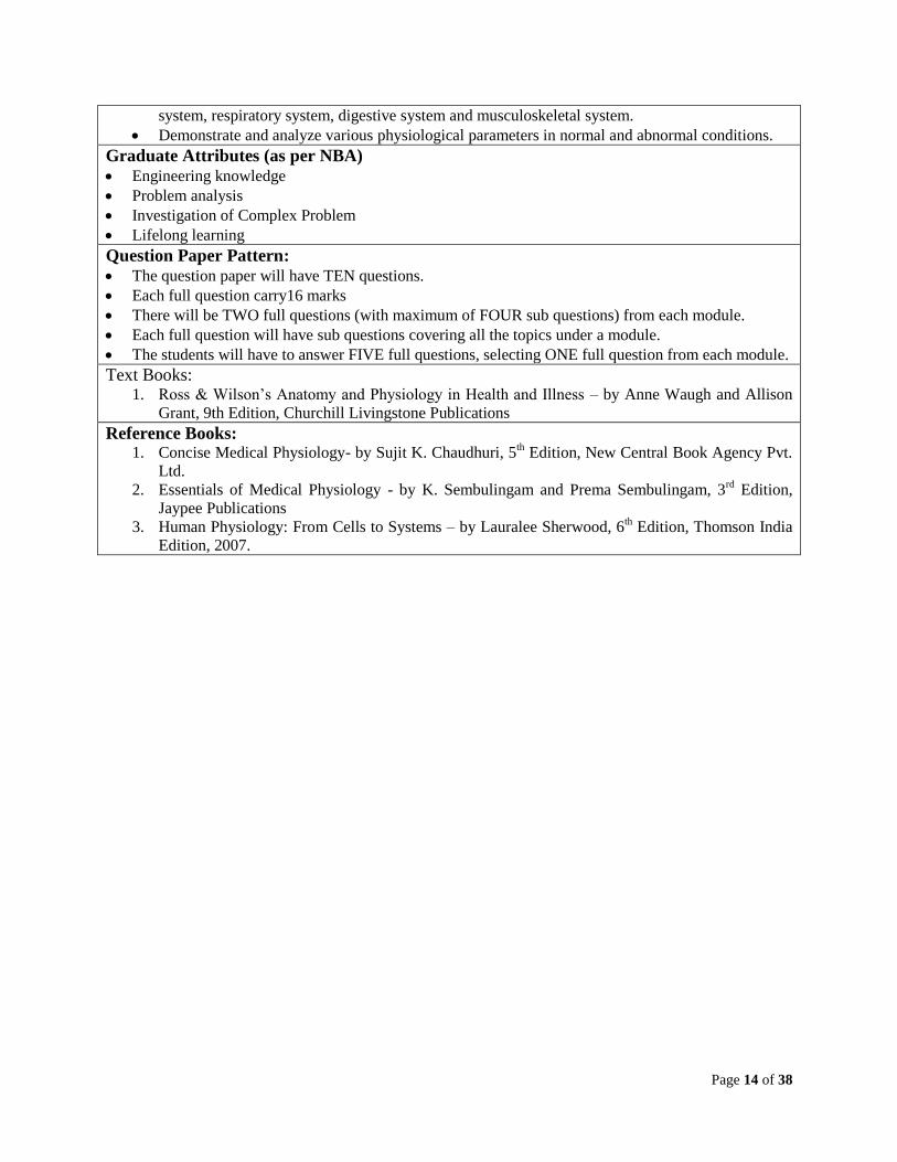
system, respiratory system, digestive system and musculoskeletal system.
Demonstrate and analyze various physiological parameters in normal and abnormal conditions.
Graduate Attributes (as per NBA)
Engineering knowledge
Problem analysis
Investigation of Complex Problem
Lifelong learning
Question Paper Pattern:
The question paper will have TEN questions.
Each full question carry16 marks
There will be TWO full questions (with maximum of FOUR sub questions) from each module.
Each full question will have sub questions covering all the topics under a module.
The students will have to answer FIVE full questions, selecting ONE full question from each module.
Text Books: 1. Ross & Wilson’s Anatomy and Physiology in Health and Illness – by Anne Waugh and Allison
Grant, 9th Edition, Churchill Livingstone Publications
Reference Books: 1. Concise Medical Physiology- by Sujit K. Chaudhuri, 5
th Edition, New Central Book Agency Pvt.
Ltd.
2. Essentials of Medical Physiology - by K. Sembulingam and Prema Sembulingam, 3rd
Edition,
Jaypee Publications
3. Human Physiology: From Cells to Systems – by Lauralee Sherwood, 6th Edition, Thomson India
Edition, 2007.
Page 15 of 38
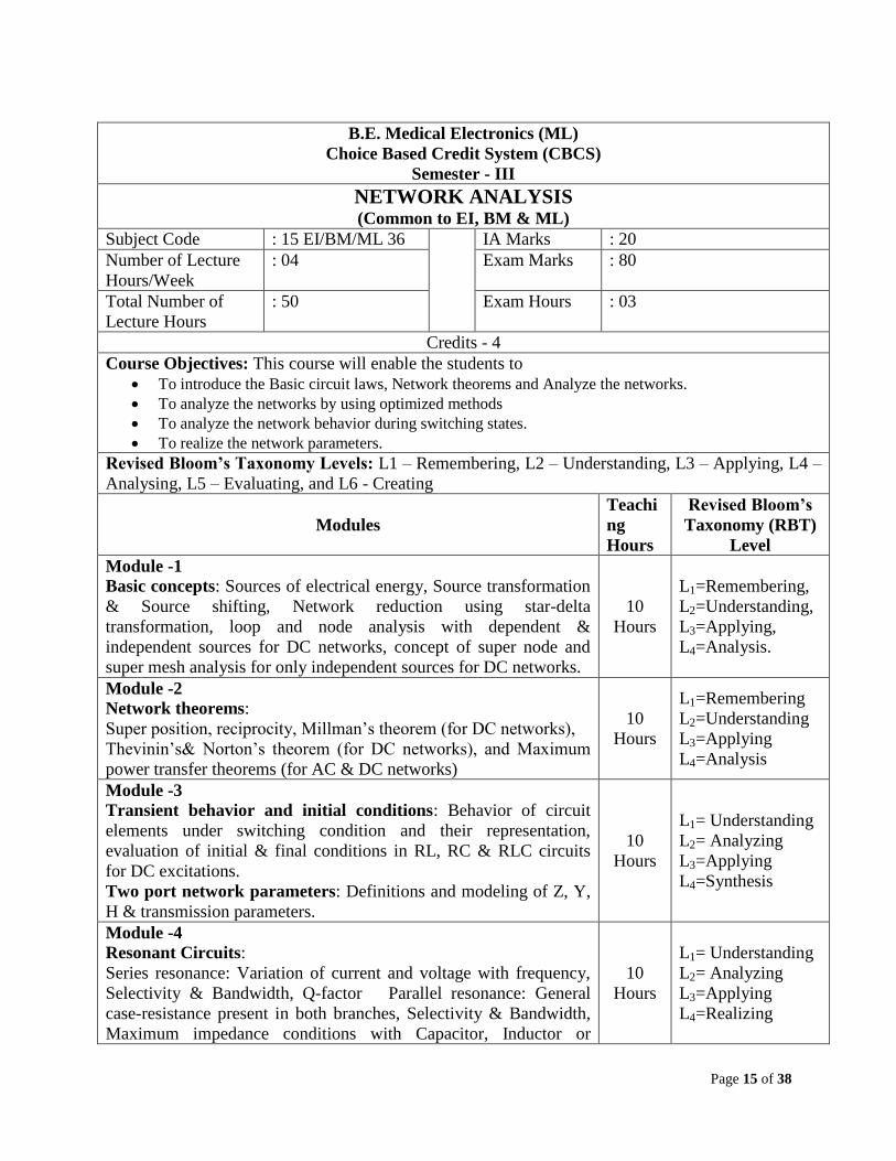
B.E. Medical Electronics (ML)
Choice Based Credit System (CBCS)
Semester - III
NETWORK ANALYSIS (Common to EI, BM & ML)
Subject Code : 15 EI/BM/ML 36 IA Marks : 20
Number of Lecture
Hours/Week
: 04 Exam Marks : 80
Total Number of
Lecture Hours
: 50 Exam Hours : 03
Credits - 4
Course Objectives: This course will enable the students to
To introduce the Basic circuit laws, Network theorems and Analyze the networks.
To analyze the networks by using optimized methods
To analyze the network behavior during switching states.
To realize the network parameters.
Revised Bloom’s Taxonomy Levels: L1 – Remembering, L2 – Understanding, L3 – Applying, L4 –
Analysing, L5 – Evaluating, and L6 - Creating
Modules
Teachi
ng
Hours
Revised Bloom’s
Taxonomy (RBT)
Level
Module -1
Basic concepts: Sources of electrical energy, Source transformation
& Source shifting, Network reduction using star-delta
transformation, loop and node analysis with dependent &
independent sources for DC networks, concept of super node and
super mesh analysis for only independent sources for DC networks.
10
Hours
L1=Remembering,
L2=Understanding,
L3=Applying,
L4=Analysis.
Module -2
Network theorems:
Super position, reciprocity, Millman’s theorem (for DC networks),
Thevinin’s& Norton’s theorem (for DC networks), and Maximum
power transfer theorems (for AC & DC networks)
10
Hours
L1=Remembering
L2=Understanding
L3=Applying
L4=Analysis
Module -3
Transient behavior and initial conditions: Behavior of circuit
elements under switching condition and their representation,
evaluation of initial & final conditions in RL, RC & RLC circuits
for DC excitations.
Two port network parameters: Definitions and modeling of Z, Y,
H & transmission parameters.
10
Hours
L1= Understanding
L2= Analyzing
L3=Applying
L4=Synthesis
Module -4
Resonant Circuits:
Series resonance: Variation of current and voltage with frequency,
Selectivity & Bandwidth, Q-factor Parallel resonance: General
case-resistance present in both branches, Selectivity & Bandwidth,
Maximum impedance conditions with Capacitor, Inductor or
10
Hours
L1= Understanding
L2= Analyzing
L3=Applying
L4=Realizing
Page 16 of 38
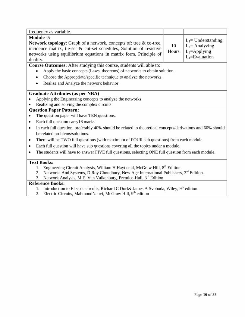
frequency as variable.
Module -5
Network topology: Graph of a network, concepts of: tree & co-tree,
incidence matrix, tie-set & cut-set schedules, Solution of resistive
networks using equilibrium equations in matrix form, Principle of
duality.
10
Hours
L1= Understanding
L2= Analyzing
L3=Applying
L4=Evaluation
Course Outcomes: After studying this course, students will able to:
Apply the basic concepts (Laws, theorems) of networks to obtain solution.
Choose the Appropriate/specific technique to analyze the networks.
Realize and Analyze the network behavior
Graduate Attributes (as per NBA)
Applying the Engineering concepts to analyze the networks
Realizing and solving the complex circuits
Question Paper Pattern:
The question paper will have TEN questions.
Each full question carry16 marks
In each full question, preferably 40% should be related to theoretical concepts/derivations and 60% should
be related problems/solutions.
There will be TWO full questions (with maximum of FOUR sub questions) from each module.
Each full question will have sub questions covering all the topics under a module.
The students will have to answer FIVE full questions, selecting ONE full question from each module.
Text Books: 1. Engineering Circuit Analysis, William H Hayt et al, McGraw Hill, 8
th Edition.
2. Networks And Systems, D Roy Choudhury, New Age International Publishers, 3rd
Edition.
3. Network Analysis, M.E. Van Valkenburg, Prentice-Hall, 3rd
Edition.
Reference Books: 1. Introduction to Electric circuits, Richard C Dorf& James A Svoboda, Wiley, 9
th edition.
2. Electric Circuits, MahmoodNahvi, McGraw Hill, 9th edition
Page 17 of 38
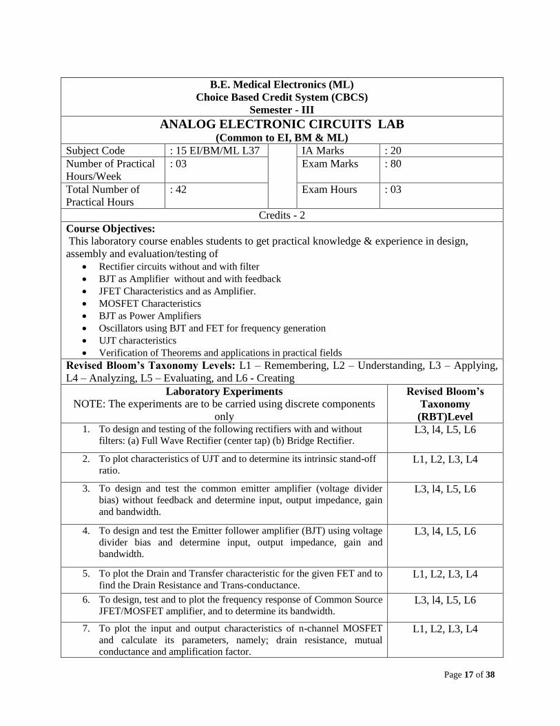
B.E. Medical Electronics (ML)
Choice Based Credit System (CBCS)
Semester - III
ANALOG ELECTRONIC CIRCUITS LAB (Common to EI, BM & ML)
Subject Code : 15 EI/BM/ML L37 IA Marks : 20
Number of Practical
Hours/Week
: 03 Exam Marks : 80
Total Number of
Practical Hours
: 42 Exam Hours : 03
Credits - 2
Course Objectives: This laboratory course enables students to get practical knowledge & experience in design,
assembly and evaluation/testing of
Rectifier circuits without and with filter
BJT as Amplifier without and with feedback
JFET Characteristics and as Amplifier.
MOSFET Characteristics
BJT as Power Amplifiers
Oscillators using BJT and FET for frequency generation
UJT characteristics
Verification of Theorems and applications in practical fields
Revised Bloom’s Taxonomy Levels: L1 – Remembering, L2 – Understanding, L3 – Applying,
L4 – Analyzing, L5 – Evaluating, and L6 - Creating
Laboratory Experiments
NOTE: The experiments are to be carried using discrete components
only
Revised Bloom’s
Taxonomy
(RBT)Level 1. To design and testing of the following rectifiers with and without
filters: (a) Full Wave Rectifier (center tap) (b) Bridge Rectifier. L3, l4, L5, L6
2. To plot characteristics of UJT and to determine its intrinsic stand-off
ratio. L1, L2, L3, L4
3. To design and test the common emitter amplifier (voltage divider
bias) without feedback and determine input, output impedance, gain
and bandwidth.
L3, l4, L5, L6
4. To design and test the Emitter follower amplifier (BJT) using voltage
divider bias and determine input, output impedance, gain and
bandwidth.
L3, l4, L5, L6
5. To plot the Drain and Transfer characteristic for the given FET and to
find the Drain Resistance and Trans-conductance. L1, L2, L3, L4
6. To design, test and to plot the frequency response of Common Source
JFET/MOSFET amplifier, and to determine its bandwidth. L3, l4, L5, L6
7. To plot the input and output characteristics of n-channel MOSFET
and calculate its parameters, namely; drain resistance, mutual
conductance and amplification factor.
L1, L2, L3, L4
Page 18 of 38
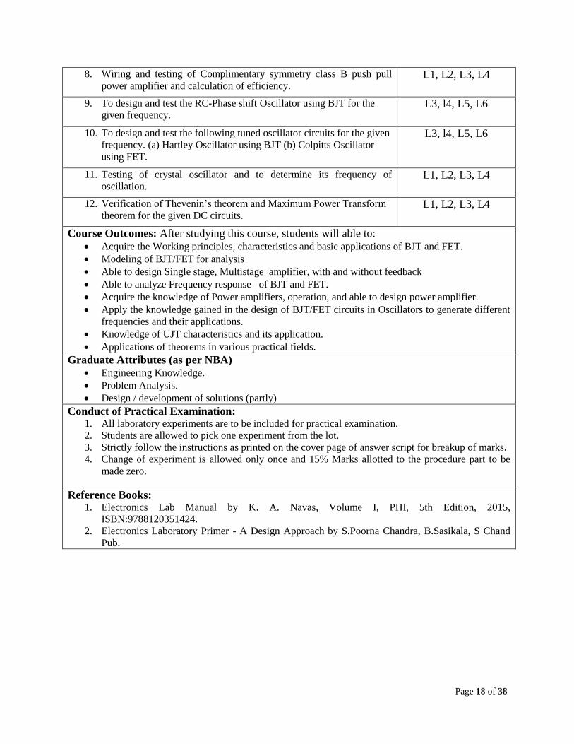
8. Wiring and testing of Complimentary symmetry class B push pull
power amplifier and calculation of efficiency. L1, L2, L3, L4
9. To design and test the RC-Phase shift Oscillator using BJT for the
given frequency. L3, l4, L5, L6
10. To design and test the following tuned oscillator circuits for the given
frequency. (a) Hartley Oscillator using BJT (b) Colpitts Oscillator
using FET.
L3, l4, L5, L6
11. Testing of crystal oscillator and to determine its frequency of
oscillation. L1, L2, L3, L4
12. Verification of Thevenin’s theorem and Maximum Power Transform
theorem for the given DC circuits. L1, L2, L3, L4
Course Outcomes: After studying this course, students will able to: Acquire the Working principles, characteristics and basic applications of BJT and FET.
Modeling of BJT/FET for analysis
Able to design Single stage, Multistage amplifier, with and without feedback
Able to analyze Frequency response of BJT and FET.
Acquire the knowledge of Power amplifiers, operation, and able to design power amplifier.
Apply the knowledge gained in the design of BJT/FET circuits in Oscillators to generate different
frequencies and their applications.
Knowledge of UJT characteristics and its application.
Applications of theorems in various practical fields.
Graduate Attributes (as per NBA)
Engineering Knowledge.
Problem Analysis.
Design / development of solutions (partly)
Conduct of Practical Examination: 1. All laboratory experiments are to be included for practical examination.
2. Students are allowed to pick one experiment from the lot.
3. Strictly follow the instructions as printed on the cover page of answer script for breakup of marks.
4. Change of experiment is allowed only once and 15% Marks allotted to the procedure part to be
made zero.
Reference Books: 1. Electronics Lab Manual by K. A. Navas, Volume I, PHI, 5th Edition, 2015,
ISBN:9788120351424.
2. Electronics Laboratory Primer - A Design Approach by S.Poorna Chandra, B.Sasikala, S Chand
Pub.
Page 19 of 38
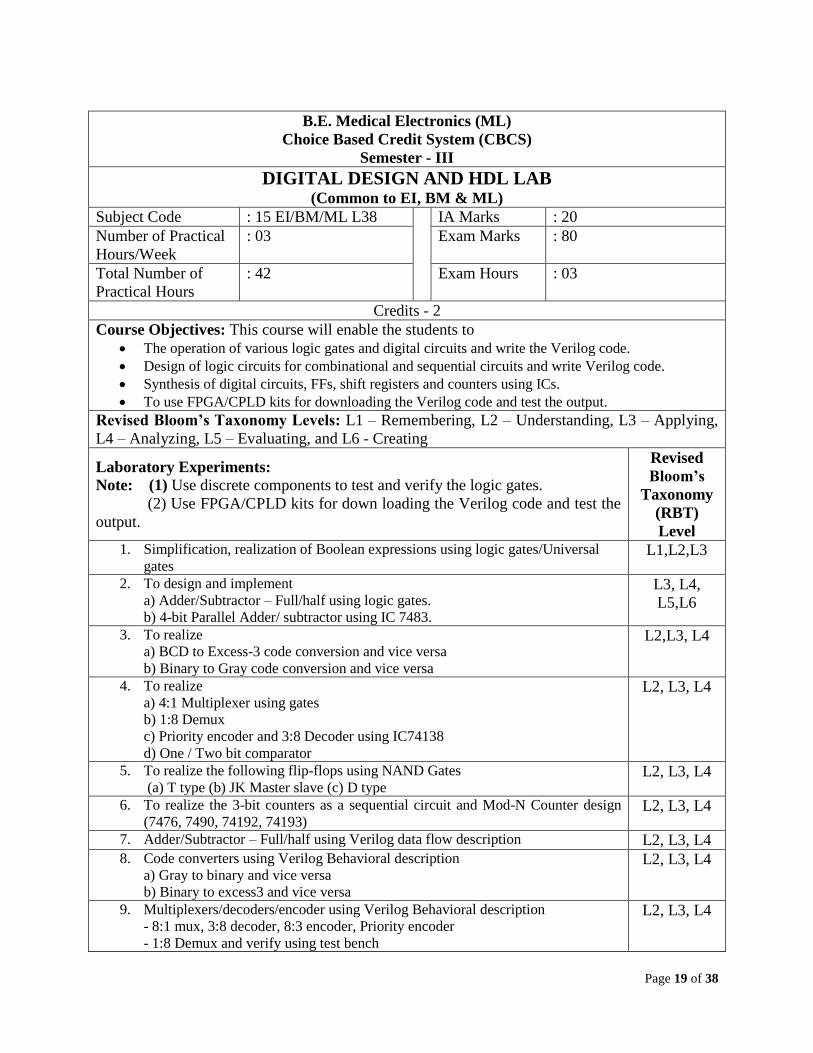
B.E. Medical Electronics (ML)
Choice Based Credit System (CBCS)
Semester - III
DIGITAL DESIGN AND HDL LAB (Common to EI, BM & ML)
Subject Code : 15 EI/BM/ML L38 IA Marks : 20
Number of Practical
Hours/Week
: 03 Exam Marks : 80
Total Number of
Practical Hours
: 42 Exam Hours : 03
Credits - 2
Course Objectives: This course will enable the students to
The operation of various logic gates and digital circuits and write the Verilog code.
Design of logic circuits for combinational and sequential circuits and write Verilog code.
Synthesis of digital circuits, FFs, shift registers and counters using ICs.
To use FPGA/CPLD kits for downloading the Verilog code and test the output.
Revised Bloom’s Taxonomy Levels: L1 – Remembering, L2 – Understanding, L3 – Applying,
L4 – Analyzing, L5 – Evaluating, and L6 - Creating
Laboratory Experiments:
Note: (1) Use discrete components to test and verify the logic gates.
(2) Use FPGA/CPLD kits for down loading the Verilog code and test the
output.
Revised
Bloom’s
Taxonomy
(RBT)
Level 1. Simplification, realization of Boolean expressions using logic gates/Universal
gates L1,L2,L3
2. To design and implement
a) Adder/Subtractor – Full/half using logic gates.
b) 4-bit Parallel Adder/ subtractor using IC 7483.
L3, L4,
L5,L6
3. To realize
a) BCD to Excess-3 code conversion and vice versa
b) Binary to Gray code conversion and vice versa
L2,L3, L4
4. To realize
a) 4:1 Multiplexer using gates
b) 1:8 Demux
c) Priority encoder and 3:8 Decoder using IC74138
d) One / Two bit comparator
L2, L3, L4
5. To realize the following flip-flops using NAND Gates
(a) T type (b) JK Master slave (c) D type L2, L3, L4
6. To realize the 3-bit counters as a sequential circuit and Mod-N Counter design
(7476, 7490, 74192, 74193) L2, L3, L4
7. Adder/Subtractor – Full/half using Verilog data flow description L2, L3, L4 8. Code converters using Verilog Behavioral description
a) Gray to binary and vice versa
b) Binary to excess3 and vice versa
L2, L3, L4
9. Multiplexers/decoders/encoder using Verilog Behavioral description
- 8:1 mux, 3:8 decoder, 8:3 encoder, Priority encoder
- 1:8 Demux and verify using test bench
L2, L3, L4
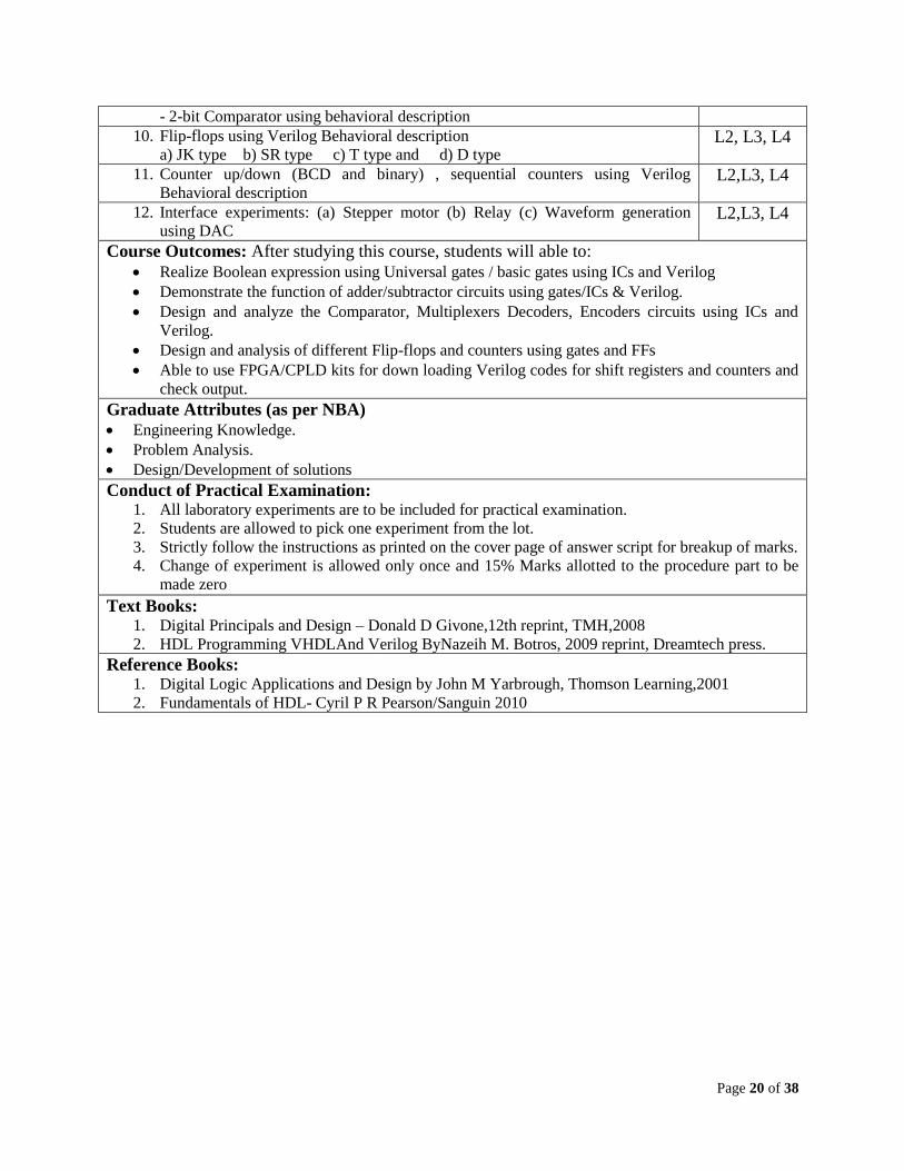
Page 20 of 38
- 2-bit Comparator using behavioral description
10. Flip-flops using Verilog Behavioral description
a) JK type b) SR type c) T type and d) D type L2, L3, L4
11. Counter up/down (BCD and binary) , sequential counters using Verilog
Behavioral description L2,L3, L4
12. Interface experiments: (a) Stepper motor (b) Relay (c) Waveform generation
using DAC L2,L3, L4
Course Outcomes: After studying this course, students will able to:
Realize Boolean expression using Universal gates / basic gates using ICs and Verilog
Demonstrate the function of adder/subtractor circuits using gates/ICs & Verilog.
Design and analyze the Comparator, Multiplexers Decoders, Encoders circuits using ICs and
Verilog.
Design and analysis of different Flip-flops and counters using gates and FFs
Able to use FPGA/CPLD kits for down loading Verilog codes for shift registers and counters and
check output.
Graduate Attributes (as per NBA)
Engineering Knowledge.
Problem Analysis.
Design/Development of solutions
Conduct of Practical Examination: 1. All laboratory experiments are to be included for practical examination.
2. Students are allowed to pick one experiment from the lot.
3. Strictly follow the instructions as printed on the cover page of answer script for breakup of marks.
4. Change of experiment is allowed only once and 15% Marks allotted to the procedure part to be
made zero
Text Books: 1. Digital Principals and Design – Donald D Givone,12th reprint, TMH,2008
2. HDL Programming VHDLAnd Verilog ByNazeih M. Botros, 2009 reprint, Dreamtech press.
Reference Books: 1. Digital Logic Applications and Design by John M Yarbrough, Thomson Learning,2001
2. Fundamentals of HDL- Cyril P R Pearson/Sanguin 2010
Page 21 of 38
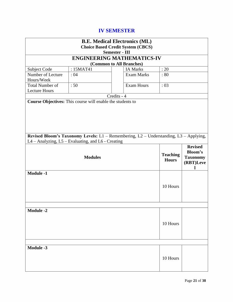
IV SEMESTER
B.E. Medical Electronics (ML) Choice Based Credit System (CBCS)
Semester - III
ENGINEERING MATHEMATICS-IV (Common to All Branches)
Subject Code : 15MAT41 IA Marks : 20
Number of Lecture
Hours/Week
: 04 Exam Marks : 80
Total Number of
Lecture Hours
: 50 Exam Hours : 03
Credits - 4
Course Objectives: This course will enable the students to
Revised Bloom’s Taxonomy Levels: L1 – Remembering, L2 – Understanding, L3 – Applying,
L4 – Analyzing, L5 – Evaluating, and L6 - Creating
Modules Teaching
Hours
Revised
Bloom’s
Taxonomy
(RBT)Leve
l
Module -1
10 Hours
Module -2
10 Hours
Module -3
10 Hours
Page 22 of 38
Module -4
10 Hours
Module -5
10 Hours
Course Outcomes: After studying this course, students will able to:
Graduate Attributes (as per NBA)
Question Paper Pattern:
The question paper will have TEN questions.
Each full question carry16 marks
There will be TWO full questions (with maximum of FOUR sub questions) from each module.
Each full question will have sub questions covering all the topics under a module.
The students will have to answer FIVE full questions, selecting ONE full question from each module.
Text Books:
Reference Books:
Page 23 of 38
IV SEMESTER
B.E. Medical Electronics (ML) Choice Based Credit System (CBCS)
Semester – IV
SIGNAL CONDITIONING AND DATA ACQUISITION CIRCUITS (Common to EI, BM & ML) [Revised]
Subject Code : 15 EI/BM/ML42 IA Marks : 20
Number of Lecture
Hours/Week
: 04 Exam Marks : 80
Total Number of
Lecture Hours
: 50 Exam Hours : 03
Credits – 4
Course Objectives: This course will enable the students to
Define and describe Op Amp, basic concepts, characteristics and specifications
Gain knowledge about Linear and nonlinear applications op-amp.
Design and develop circuits like, amplifiers, filters, Timers to meet industrial requirements.
Get a firm grasp of basic principles of op-amp.
Revised Bloom’s Taxonomy Levels: L1 – Remembering, L2 – Understanding, L3 – Applying,
L4 – Analyzing, L5 – Evaluating, and L6 – Creating
Modules Teaching
Hours
Revised
Bloom’s
Taxonomy
(RBT)Level
Module -1
Introduction to Operational Amplifiers: Introduction, Block
schematic of an Op-amp, Power supply connections, Characteristics of
an Ideal OP-AMP, Inverting Amplifier, Non-inverting Amplifier,
Voltage follower, Differential Amplifier, CMRR. (Relevant
problems).
Operational Amplifier Characteristics: DC characteristics – Input
bias current, Input offset current, Input offset voltage, Total output
offset voltage, Thermal drift. AC characteristics – Frequency response,
Slew rate, PSRR.
Basic op-amp applications – Scale changer/Inverter.
Summing amplifier: Inverting summing amplifier, Non-inverting
Summing amplifier, Subtractor, Instrumentation Amplifier. (Relevant
problems).
10 Hours
L1,L2, L3,L4
Module -2
Operational Amplifier Applications: V – I and I – V converter, Op-
amp circuit using diodes, sample and hold circuit, Differentiator and
Integrator.
Comparator and waveforms generator: Comparator, Regenerative
comparator (Schmitt Trigger), Astable mutivibrator, Monostable
10 Hours L1,L2, L3,L4
Page 24 of 38
multivibrator and Triangular waveform generator. Phase shift
oscillator, Wien bridge oscillator. (Relevant problems).
Module -3
Voltage Regulators: Introduction, Series Op-amp regulator, IC
voltage regulators, 723 general purpose regulators, switching
regulator.
Active filters: First and Second order LPF, First and Second orders
HPF, Band Pass Filters, Band Reject filters. (Design examples).
10 Hours L1,L2, L3,L4
Module -4
555 Timer: Description of Functional Diagram, Monostable
operation, Applications of Monostable Multivibrator: Frequency
Divider & Pulse Width Modulation. Astable operation, Applications
of Astable Multivibrator: FSK Generator and Pulse Position
Modulation.
Phase Locked Loops: Basic Principles, Analog phase
Detector/comparator, Voltage controlled oscillator. PLL applications:
Frequency Multiplication/Division, Frequency translation, FM
demodulation.
10 Hours L2,L3,L4,
L5, L6
Module -5
Data Acquisition Systems: Types of instrumentation systems,
Components of analog data acquisition system, Digital data
acquisition system, Use of recorders in digital systems, Digital
recording systems.
Data Converters:
Digital to Analog Converters: Basic DAC techniques, Weighted
Resistor DAC, R – 2R Ladder DAC, DAC 0800 (Data sheet: Features
and description only).
Analog to Digital Converters: Functional diagram of ADC, Flash
ADC, Counter type ADC, Successive approximation ADC, Dual slope
ADC. ADC 0809 (Data sheet: Features, specifications and description
only), DAC/ADC specifications.
10 Hours L2, L3,L4,
L5, L6
Course Outcomes: After studying this course, students will able to: 1. Understand the basic principles and operation of op-amp.
2. Design and develop circuits to meet the practical applications
3. Implement and integrate the op-amp circuits in electronic gadgets.
Graduate Attributes (as per NBA)
Engineering knowledge
Problem analysis
Design & development of solutions
Investigation of Complex Problem
Question Paper Pattern:
The question paper will have TEN questions.
Page 25 of 38
Each full question carry 16 marks
There will be TWO full questions (with maximum of FOUR sub questions) from each module.
Each full question will have sub questions covering all the topics under a module.
The students will have to answer FIVE full questions, selecting ONE full question from each module.
Text Books:
1. “Linear Integrated Circuits”, D. Roy Choudhury and Shail B. Jain, 4th edition, Reprint 2010, New
Age International. (Module -1,2,3,4 & 5)
2. “Op - Amps and Linear Integrated Circuits”, Ramakant A. Gayakwad, 4th edition, PHI (Module-3)
3. “A course in Electrical & Electronic Measurements & Instrumentation”, A K Sawhney, Dhanpat
Rai Publications, 19th edition, 2011.(Module-5)
Reference Books:
1. “Operational Amplifiers and Linear Integrated Circuits”, Robert. F. Coughlin &Fred. F. Driscoll,
PHI/Pearson, 2006
2. “Op - Amps and Linear Integrated Circuits”, James M. Fiore, Thomson Learning, 2001
3. “Design with Operational Amplifiers and Analog Integrated Circuits”, Sergio Franco, TMH, 3e,
2005
Page 26 of 38
B.E. Medical Electronics (ML)
Choice Based Credit System (CBCS)
Semester - III
EMBEDDED CONTROLLERS (Common to EI, BM & ML)
Subject Code : 15 EI/BM/ML 43 IA Marks : 20
Number of Lecture
Hours/Week
: 04 Exam Marks : 80
total number of
lecture hours
: 50 exam hours : 03
Credits - 4
Course Objectives:This course enables students to understand:
Basics of Microprocessor and Microcontroller
8051 Microcontroller architecture and Pin description
8051 Addressing modes and instruction set
Programming of on-chip peripherals in 8051
Design and develop applications using 8051 Assembly language and C program.
MSP 430 Microcontroller architecture
On-chip peripherals and program using Assembly language and C.
Revised Bloom’s Taxonomy Levels: L1 – Remembering, L2 – Understanding, L3 – Applying,
L4 – Analyzing, L5 – Evaluating, and L6 - Creating
Modules Teaching
Hours
Revised
Bloom’s
Taxonomy
(RBT)Level
Module -1
Microprocessor and Microcontrollers:
Introduction: Microprocessor and Microcontroller, Microprocessor
survey, RISC and CISC, CPU Architecture, Harvard and Von-
Neumann, CPU Architecture. 8051 Microcontroller Architecture. Pin
functions organizations Input/ Output pins, ports and circuits. Internal
and External memory Architecture. 8051 Reg. banks and stack, 8051
flag bits and PSW Register. Special function Registers. Timer /Counter,
Serial data input/ output, Interrupts, program counter and ROM space in
the 8051.
10 Hours L1,L2
Module -2
Addressing modes directives instruction set of 8051
Microcontroller. Immediate and Register addressing modes. Accessing
memory using various addressing modes. Bit addressing for I/o and
RAM 8051 data types and directives. Jump Loop and CALL
Instructions Arithmetic and Logic Instructions and programming I/o
port programming. Assembly Language programs using various
Instructions.
10 Hours L1,L2
Page 27 of 38
Module -3
8051 programming in C and interfacing. Data types and time delay in
8051 C, I/o programming, Logic operation, data conversion programs,
accessing Code ROM Space, data serialization. 8051 interfacing to
LCD and key board, DAC, stepper motor, DC Motor, Parallel and serial
ADC. Elevator.
10 Hours L2,L3,L4
Module -4
Timer/ Counter, Serial communication and Interrupts in 8051.
Programming 8051 timer/ counter, programming timer 0 and 1 in 8051
C, Basics of serial communication, 8051 connections to RS-232. 8051
serial port programming in assembly and C. 8051 Interrupts,
Programming Timer Interrupts, External hardware Interrupts and serial
communication Interrupts. Interrupts priority & Interrupt programming
in C.
10 Hours L2,L3,L4,L
5
Module -5
Introduction to Advanced Microcontrollers. Salient Features of
Advanced Microcontrollers. MSP430F2013 Architecture and pin
functions, Memory, Clock Generator, CPU Registers, Addressing
modes, Instruction set and emulated Instruction set. Development
Environment. Aspects of C for embedded system, Introduction to MSP
430 starter kit, parallel ports.
10 Hours L1,L2,L3
Course Outcomes:After studying this course , Student will be able to:
Learn architecture of 8051 and MSP 430.
Learn programming skills using Assembly language and C
Design and interfacing of microcontroller based embedded systems.
Build projects
Graduate Attributes (as per NBA)
Engineering Knowledge
Problem Analysis
Design and Development of solutions
Modern Tool usage
Question Paper Pattern:
The question paper will have TEN questions.
Each full question carry 16 marks
There will be TWO full questions (with maximum of FOUR sub questions) from each module.
Each full question will have sub questions covering all the topics under a module.
The students will have to answer FIVE full questions, selecting ONE full question from each module.
Text Books: 1. “The 8051 Microcontroller and Embedded systems-using assembly and C”, Muhammad Ali
Mazidi and Janice Gillespie Mazidi and Rollin D. McKinaly,PHI,2006/pearson,2006
2. “MSP430 Microcontroller Basics” John H. Davis, , Elsevier 2010.
3. “Embedded Systems Design using the TI MSP430 series”, Cris Nagy, Newnes, Elsevier.

Page 28 of 38
Reference Books: 1. “The 8051 Microcontroller architecture. Programming and applications”, Kenneth J Alyala
Thomson learning 2005.
2. “The 8051 Microcontroller: Hardware, Software and Applications” V. Udhayashankara and
MallikarjunaSwamy ,TMH., 2009.
Page 29 of 38
B.E. Medical Electronics (ML)
Choice Based Credit System (CBCS)
Semester - IV
SIGNALS AND SYSTEMS Subject Code : 15ML44 IA Marks : 20
Number of Lecture
Hours/Week
: 04 Exam Marks : 80
Total Number of
Lecture Hours
: 50 Exam Hours : 03
Credits - 4 Course Objectives: This course will enable the students
Coverage of continuous and discrete-time signals and systems, their properties and representations
and methods that is necessary for the analysis of continuous and discrete-time signals and systems.
Knowledge of time-domain representation and analysis concepts as they relate to difference
equations, impulse response and convolution, etc.
Knowledge of frequency-domain representation and analysis concepts using Fourier analysis tools,
Z-transform.
Concepts of the sampling process.
Mathematical and computational skills needed in application areas like communication, signal
processing and control, which will be taught in other courses.
Revised Bloom’s Taxonomy Levels: L1 – Remembering, L2 – Understanding, L3 – Applying, L4
– Analyzing, L5 – Evaluating, and L6 - Creating
Modules Teaching
Hours
Revised
Bloom’s
Taxonomy
(RBT)Level
Module -1 Introduction: Definitions of a signal and a system, classification of signals,
basic operations on signals, elementary signals, Systems viewed as
interconnections of operations, properties of systems. Introduction to
physiological signals.
10 Hours L1, L2, L3
Module -2 Time-domain representations for LTI systems: Convolution, Impulse
response representation, Convolution Sum and Convolution Integral.
Properties of impulse response representation, Differential and difference
equation representations, Block diagram representations. The above concepts
can be implemented by using Matlab.
10 Hours L1, L2, L3,
L4
Module -3 Fourier representation of signals: Introduction, Discrete time, continuous
time Fourier series Continuous Fourier transforms (derivations of transforms
and properties are excluded). Discrete Fourier transforms (derivations of
transforms and properties are excluded) and their properties. The above
concepts can be implemented by using Matlab.
10 Hours L1, L2, L3,
L4
Page 30 of 38
Module -4 Applications of Fourier representations: Introduction, Frequency response
of LTI systems, Fourier transforms representation of periodic signals, Fourier
transform representation of discrete time signals. Synthesis of a physiological
signal using Fourier series and Fourier transform.
10 Hours L1, L2, L3,
L4
Module -5 Z-Transform: Introduction, properties of ROC, properties of Z-Transform,
inversion of Z-transform, transform analysis of LTI Systems, transfer function,
stability and causality, unilateral Z- Transform and its application to solve
difference equations. Analysis of Physiological signals using ZT.
10 Hours L1, L2, L3,
L4
Course Outcomes: After studying this course, students will able to: 1. Characterize and analyze the properties of CT and DT signals and systems
2. Analyze CT and DT systems in Time domain using convolution and differential equation
3. Represent CT and DT systems in the Frequency domain using Fourier analysis tools like CTFS,
CTFT, DTFS and DTFT.
4. Conceptualize the effects of sampling a CT signal and analyze CT and DT systems using Z
Transforms
Graduate Attributes (as per NBA)
Engineering Knowledge
Problem Analysis
Design / development of solutions
Interpretation of data
Question Paper Pattern:
The question paper will have TEN questions.
Each full question carry 16 marks
There will be TWO full questions (with maximum of FOUR sub questions) from each module.
Each full question will have sub questions covering all the topics under a module.
The students will have to answer FIVE full questions, selecting ONE full question from each module.
Text Books: 1. Simon Haykin and Barry Van Veen “Signals and Systems”, John Wiley & Sons, 2
nd edition,2012
2. Suresh R. Devasahayam, Signals and systems in biomedical engineering, Plenum Publishers, 2000.
Reference Books: 1. Alan V Oppenheim, Alan S, Willsky and A Hamid Nawab, “Signals and Systems” Pearson
Education \ Asia / PHI, 3nd edition, 1997. Indian Reprint 2011
2. H. P Hsu, R. Ranjan, “Signals and Systems”, Scham’s outlines, TMH, 2011
3. B. P. Lathi, “Linear Systems and Signals”, Oxford University Press, 2010
4. Ganesh Rao and Satish Tunga, “Signals and Systems”, Sanguine Technical Publishers, 2012.
Page 31 of 38
B.E. Medical Electronics (ML)
Choice Based Credit System (CBCS)
Semester - IV
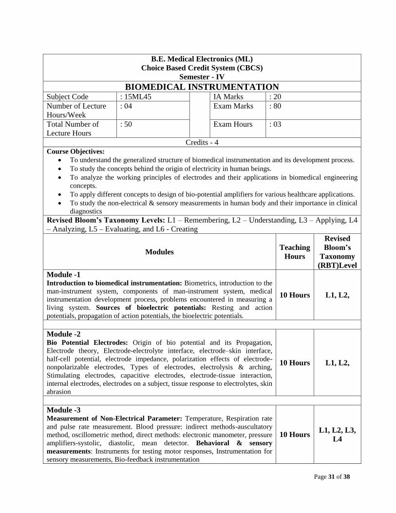
BIOMEDICAL INSTRUMENTATION Subject Code : 15ML45 IA Marks : 20
Number of Lecture
Hours/Week
: 04 Exam Marks : 80
Total Number of
Lecture Hours
: 50 Exam Hours : 03
Credits - 4
Course Objectives:
To understand the generalized structure of biomedical instrumentation and its development process.
To study the concepts behind the origin of electricity in human beings.
To analyze the working principles of electrodes and their applications in biomedical engineering
concepts.
To apply different concepts to design of bio-potential amplifiers for various healthcare applications.
To study the non-electrical & sensory measurements in human body and their importance in clinical
diagnostics
Revised Bloom’s Taxonomy Levels: L1 – Remembering, L2 – Understanding, L3 – Applying, L4
– Analyzing, L5 – Evaluating, and L6 - Creating
Modules Teaching
Hours
Revised
Bloom’s
Taxonomy
(RBT)Level
Module -1 Introduction to biomedical instrumentation: Biometrics, introduction to the
man-instrument system, components of man-instrument system, medical
instrumentation development process, problems encountered in measuring a
living system. Sources of bioelectric potentials: Resting and action
potentials, propagation of action potentials, the bioelectric potentials.
10 Hours L1, L2,
Module -2 Bio Potential Electrodes: Origin of bio potential and its Propagation,
Electrode theory, Electrode-electrolyte interface, electrode–skin interface,
half-cell potential, electrode impedance, polarization effects of electrode-
nonpolarizable electrodes, Types of electrodes, electrolysis & arching,
Stimulating electrodes, capacitive electrodes, electrode-tissue interaction,
internal electrodes, electrodes on a subject, tissue response to electrolytes, skin
abrasion
10 Hours L1, L2,
Module -3 Measurement of Non-Electrical Parameter: Temperature, Respiration rate
and pulse rate measurement. Blood pressure: indirect methods-auscultatory
method, oscillometric method, direct methods: electronic manometer, pressure
amplifiers-systolic, diastolic, mean detector. Behavioral & sensory
measurements: Instruments for testing motor responses, Instrumentation for
sensory measurements, Bio-feedback instrumentation
10 Hours L1, L2, L3,
L4
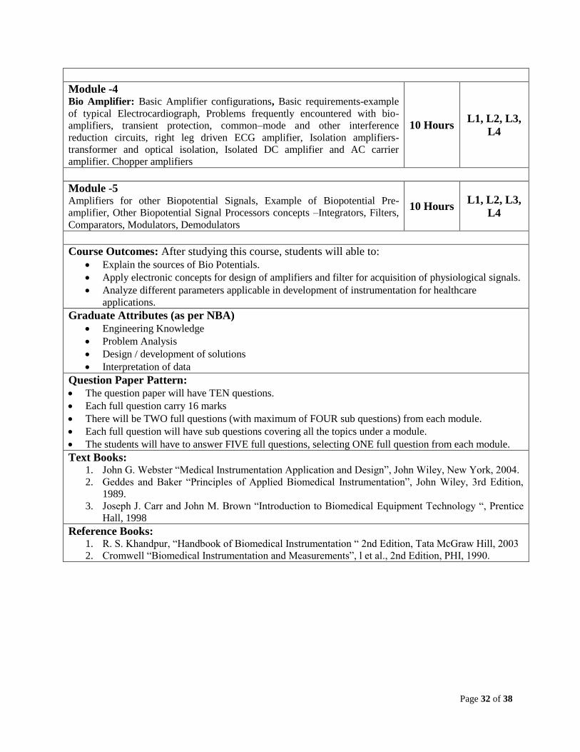
Page 32 of 38
Module -4 Bio Amplifier: Basic Amplifier configurations, Basic requirements-example
of typical Electrocardiograph, Problems frequently encountered with bio-
amplifiers, transient protection, common–mode and other interference
reduction circuits, right leg driven ECG amplifier, Isolation amplifiers-
transformer and optical isolation, Isolated DC amplifier and AC carrier
amplifier. Chopper amplifiers
10 Hours L1, L2, L3,
L4
Module -5 Amplifiers for other Biopotential Signals, Example of Biopotential Pre-
amplifier, Other Biopotential Signal Processors concepts –Integrators, Filters,
Comparators, Modulators, Demodulators
10 Hours L1, L2, L3,
L4
Course Outcomes: After studying this course, students will able to:
Explain the sources of Bio Potentials.
Apply electronic concepts for design of amplifiers and filter for acquisition of physiological signals.
Analyze different parameters applicable in development of instrumentation for healthcare
applications.
Graduate Attributes (as per NBA)
Engineering Knowledge
Problem Analysis
Design / development of solutions
Interpretation of data
Question Paper Pattern:
The question paper will have TEN questions.
Each full question carry 16 marks
There will be TWO full questions (with maximum of FOUR sub questions) from each module.
Each full question will have sub questions covering all the topics under a module.
The students will have to answer FIVE full questions, selecting ONE full question from each module.
Text Books: 1. John G. Webster “Medical Instrumentation Application and Design”, John Wiley, New York, 2004.
2. Geddes and Baker “Principles of Applied Biomedical Instrumentation”, John Wiley, 3rd Edition,
1989.
3. Joseph J. Carr and John M. Brown “Introduction to Biomedical Equipment Technology “, Prentice
Hall, 1998
Reference Books: 1. R. S. Khandpur, “Handbook of Biomedical Instrumentation “ 2nd Edition, Tata McGraw Hill, 2003
2. Cromwell “Biomedical Instrumentation and Measurements”, l et al., 2nd Edition, PHI, 1990.
Page 33 of 38
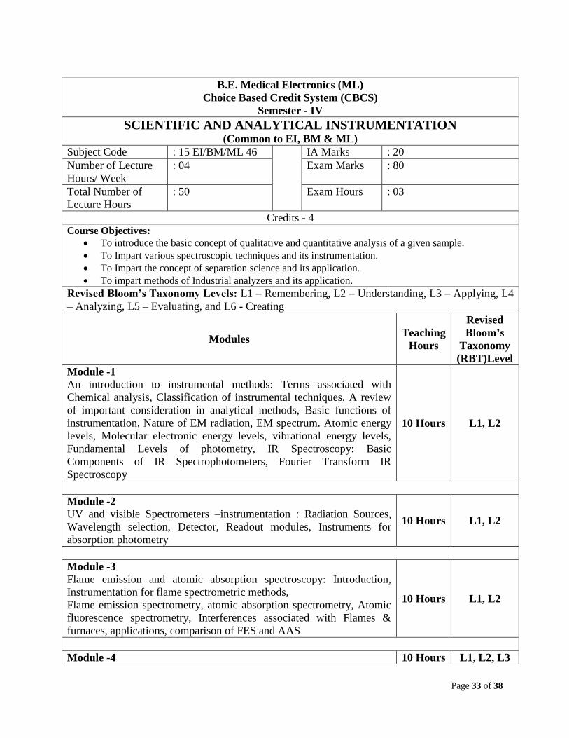
B.E. Medical Electronics (ML)
Choice Based Credit System (CBCS)
Semester - IV
SCIENTIFIC AND ANALYTICAL INSTRUMENTATION (Common to EI, BM & ML)
Subject Code : 15 EI/BM/ML 46 IA Marks : 20
Number of Lecture
Hours/ Week
: 04 Exam Marks : 80
Total Number of
Lecture Hours
: 50 Exam Hours : 03
Credits - 4
Course Objectives:
To introduce the basic concept of qualitative and quantitative analysis of a given sample.
To Impart various spectroscopic techniques and its instrumentation.
To Impart the concept of separation science and its application.
To impart methods of Industrial analyzers and its application.
Revised Bloom’s Taxonomy Levels: L1 – Remembering, L2 – Understanding, L3 – Applying, L4
– Analyzing, L5 – Evaluating, and L6 - Creating
Modules Teaching
Hours
Revised
Bloom’s
Taxonomy
(RBT)Level
Module -1
An introduction to instrumental methods: Terms associated with
Chemical analysis, Classification of instrumental techniques, A review
of important consideration in analytical methods, Basic functions of
instrumentation, Nature of EM radiation, EM spectrum. Atomic energy
levels, Molecular electronic energy levels, vibrational energy levels,
Fundamental Levels of photometry, IR Spectroscopy: Basic
Components of IR Spectrophotometers, Fourier Transform IR
Spectroscopy
10 Hours L1, L2
Module -2
UV and visible Spectrometers –instrumentation : Radiation Sources,
Wavelength selection, Detector, Readout modules, Instruments for
absorption photometry
10 Hours L1, L2
Module -3
Flame emission and atomic absorption spectroscopy: Introduction,
Instrumentation for flame spectrometric methods,
Flame emission spectrometry, atomic absorption spectrometry, Atomic
fluorescence spectrometry, Interferences associated with Flames &
furnaces, applications, comparison of FES and AAS
10 Hours L1, L2
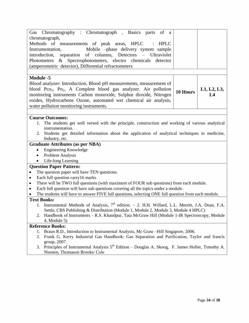
Module -4 10 Hours L1, L2, L3
Page 34 of 38
Gas Chromatography : Chromatograph , Basics parts of a
chromatograph,
Methods of measurements of peak areas, HPLC : HPLC
Instrumentation, Mobile –phase delivery system sample
introduction, separation of columns, Detectors – Ultraviolet
Photometers & Spectrophotometers, electro chemicals detector
(amperometric detector), Differential refractometers
Module -5
Blood analyzer: Introduction, Blood pH measurements, measurement of
blood Pco2, Po2, A Complete blood gas analyzer. Air pollution
monitoring instruments Carbon monoxide, Sulphur dioxide, Nitrogen
oxides, Hydrocarbons Ozone, automated wet chemical air analysis,
water pollution monitoring instruments.
10 Hours L1, L2, L3,
L4
Course Outcomes: 1. The students get well versed with the principle, construction and working of various analytical
instrumentation.
2. Students get detailed information about the application of analytical techniques in medicine,
Industry, etc.
Graduate Attributes (as per NBA)
Engineering Knowledge
Problem Analysis
Life-long Learning
Question Paper Pattern:
The question paper will have TEN questions.
Each full question carry16 marks
There will be TWO full questions (with maximum of FOUR sub questions) from each module.
Each full question will have sub questions covering all the topics under a module.
The students will have to answer FIVE full questions, selecting ONE full question from each module.
Text Books: 1. Instrumental Methods of Analysis, 7
th edition. – 2. H.H. Willard, L.L. Merritt, J.A. Dean, F.A.
Settle, CBS Publishing & Distribution (Module 1, Module 2, Module 3, Module 4 HPLC)
2. Handbook of Instruments – R.S. Khandpur, Tata McGraw Hill (Module 1-IR Spectroscopy, Module
4, Module 5)
Reference Books: 1. Braun R.D., Introduction to Instrumental Analysis, Mc Graw –Hill Singapore, 2006.
2. Frank G. Kerry Industrial Gas Handbook: Gas Separation and Purification, Taylor and francis
group, 2007.
3. Principles of Instrumental Analysis 5th Edition – Douglas A. Skoog, F. James Holler, Timothy A.
Niemen, Thomason Brooks/ Cole
Page 35 of 38
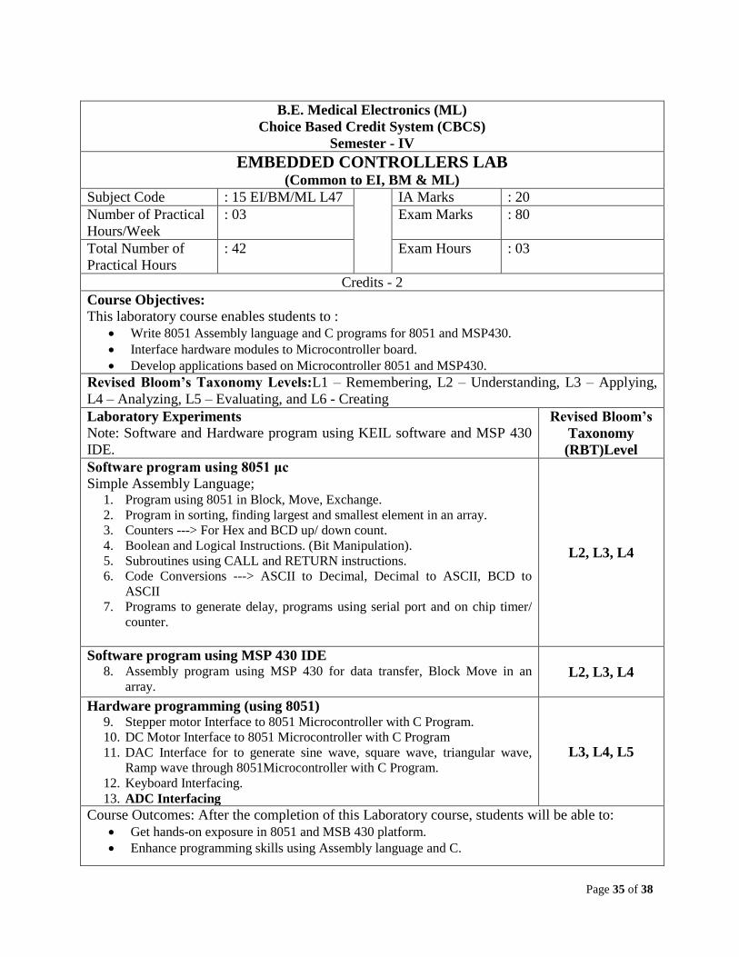
B.E. Medical Electronics (ML)
Choice Based Credit System (CBCS)
Semester - IV
EMBEDDED CONTROLLERS LAB (Common to EI, BM & ML)
Subject Code : 15 EI/BM/ML L47 IA Marks : 20
Number of Practical
Hours/Week
: 03 Exam Marks : 80
Total Number of
Practical Hours
: 42 Exam Hours : 03
Credits - 2
Course Objectives:
This laboratory course enables students to :
Write 8051 Assembly language and C programs for 8051 and MSP430.
Interface hardware modules to Microcontroller board.
Develop applications based on Microcontroller 8051 and MSP430.
Revised Bloom’s Taxonomy Levels:L1 – Remembering, L2 – Understanding, L3 – Applying,
L4 – Analyzing, L5 – Evaluating, and L6 - Creating
Laboratory Experiments
Note: Software and Hardware program using KEIL software and MSP 430
IDE.
Revised Bloom’s
Taxonomy
(RBT)Level
Software program using 8051 μc
Simple Assembly Language; 1. Program using 8051 in Block, Move, Exchange.
2. Program in sorting, finding largest and smallest element in an array.
3. Counters ---> For Hex and BCD up/ down count.
4. Boolean and Logical Instructions. (Bit Manipulation).
5. Subroutines using CALL and RETURN instructions.
6. Code Conversions ---> ASCII to Decimal, Decimal to ASCII, BCD to
ASCII
7. Programs to generate delay, programs using serial port and on chip timer/
counter.
L2, L3, L4
Software program using MSP 430 IDE 8. Assembly program using MSP 430 for data transfer, Block Move in an
array. L2, L3, L4
Hardware programming (using 8051) 9. Stepper motor Interface to 8051 Microcontroller with C Program.
10. DC Motor Interface to 8051 Microcontroller with C Program
11. DAC Interface for to generate sine wave, square wave, triangular wave,
Ramp wave through 8051Microcontroller with C Program.
12. Keyboard Interfacing.
13. ADC Interfacing
L3, L4, L5
Course Outcomes: After the completion of this Laboratory course, students will be able to:
Get hands-on exposure in 8051 and MSB 430 platform.
Enhance programming skills using Assembly language and C.
Page 36 of 38
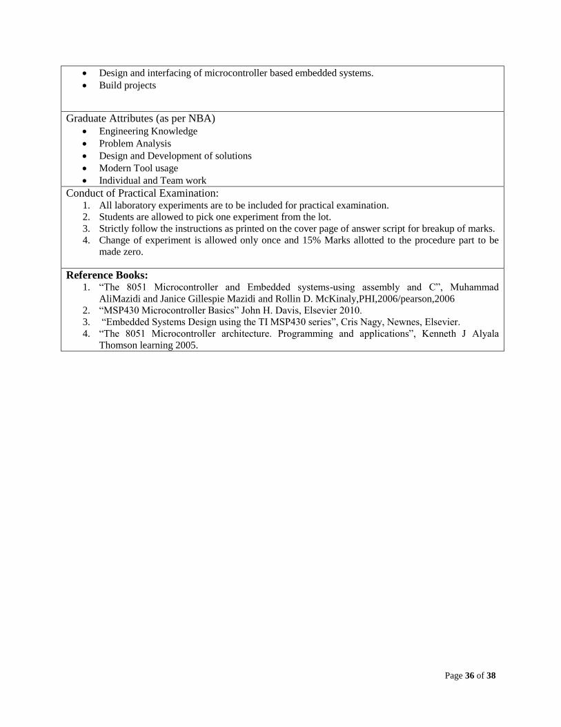
Design and interfacing of microcontroller based embedded systems.
Build projects
Graduate Attributes (as per NBA)
Engineering Knowledge
Problem Analysis
Design and Development of solutions
Modern Tool usage
Individual and Team work
Conduct of Practical Examination: 1. All laboratory experiments are to be included for practical examination.
2. Students are allowed to pick one experiment from the lot.
3. Strictly follow the instructions as printed on the cover page of answer script for breakup of marks.
4. Change of experiment is allowed only once and 15% Marks allotted to the procedure part to be
made zero.
Reference Books: 1. “The 8051 Microcontroller and Embedded systems-using assembly and C”, Muhammad
AliMazidi and Janice Gillespie Mazidi and Rollin D. McKinaly,PHI,2006/pearson,2006
2. “MSP430 Microcontroller Basics” John H. Davis, Elsevier 2010.
3. “Embedded Systems Design using the TI MSP430 series”, Cris Nagy, Newnes, Elsevier.
4. “The 8051 Microcontroller architecture. Programming and applications”, Kenneth J Alyala
Thomson learning 2005.
Page 37 of 38
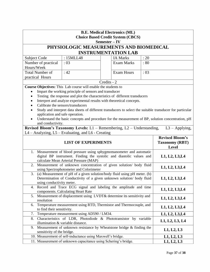
B.E. Medical Electronics (ML)
Choice Based Credit System (CBCS)
Semester – IV
PHYSIOLOGIC MEASUREMENTS AND BIOMEDICAL
INSTRUMENTATION LAB Subject Code : 15MLL48 IA Marks : 20
Number of practical
Hours/Week
: 03 Exam Marks : 80
Total Number of
practical Hours
: 42 Exam Hours : 03
Credits - 2 Course Objectives: This Lab course will enable the students to
Impart the working principle of sensors and transducer
Testing the response and plot the characteristics of different transducers
Interpret and analyze experimental results with theoretical concepts.
Calibrate the sensors/transducers
Study and interpret data sheets of different transducers to select the suitable transducer for particular
application and safe operation.
Understand the basic concepts and procedure for the measurement of BP, solution concentration, pH
and conductivity.
Revised Bloom’s Taxonomy Levels: L1 – Remembering, L2 – Understanding, L3 – Applying,
L4 – Analyzing, L5 – Evaluating, and L6 - Creating
LIST OF EXPERIMENTS
Revised Bloom’s
Taxonomy (RBT)
Level 1. Measurement of blood pressure using sphygmomanometer and automatic
digital BP instrument. Finding the systolic and diastolic values and
calculate Mean Arterial Pressure (MAP) L1, L2, L3,L4
2. Measurement of unknown concentration of given solution/ body fluid
using Spectrophotometer and Colorimeter L1, L2, L3,L4
3. (a) Measurement of pH of a given solution/body fluid using pH meter. (b)
Determination of Conductivity of a given unknown solution/ body fluid
using conductivity meter. L1, L2, L3,L4
4. Record and Trace ECG signal and labeling the amplitude and time
components. Calculating Heart Rate L1, L2, L3,L4
5. Measurement of displacement using LVDT& determine its sensitivity and
resolution L1, L2, L3,L4
6. Temperature measurement using RTD, Thermistor and Thermocouple, and
to find their sensitivity. L1, L2, L3,L4
7. Temperature measurement using AD590 / LM34. L1, L2, L3,L4 8. Characteristics of LDR, Photodiode & Phototransistor by variable
illumination & variable distance. L1, L2, L3, L4
9. Measurement of unknown resistance by Wheatstone bridge & finding the
sensitivity of the bridge. L1, L2, L3
10. Measurement of self-inductance using Maxwell’s bridge. L1, L2, L3 11. Measurement of unknown capacitance using Schering’s bridge. L1, L2, L3
Page 38 of 38
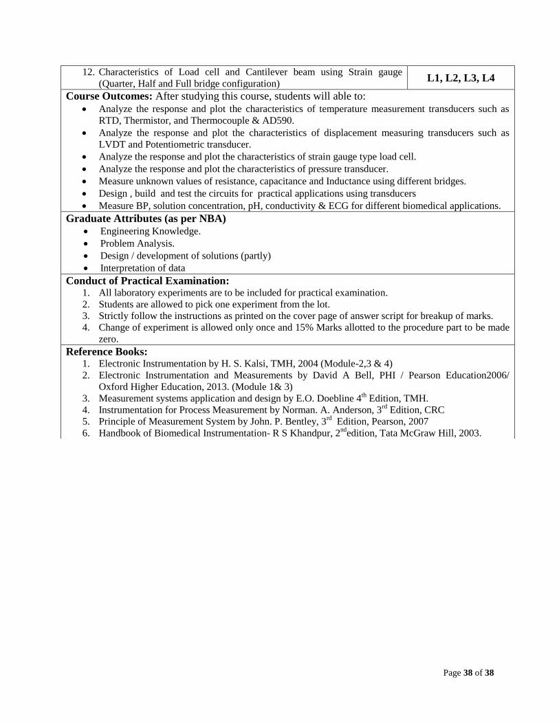
12. Characteristics of Load cell and Cantilever beam using Strain gauge
(Quarter, Half and Full bridge configuration) L1, L2, L3, L4
Course Outcomes: After studying this course, students will able to:
Analyze the response and plot the characteristics of temperature measurement transducers such as
RTD, Thermistor, and Thermocouple & AD590.
Analyze the response and plot the characteristics of displacement measuring transducers such as
LVDT and Potentiometric transducer.
Analyze the response and plot the characteristics of strain gauge type load cell.
Analyze the response and plot the characteristics of pressure transducer.
Measure unknown values of resistance, capacitance and Inductance using different bridges.
Design , build and test the circuits for practical applications using transducers
Measure BP, solution concentration, pH, conductivity & ECG for different biomedical applications.
Graduate Attributes (as per NBA)
Engineering Knowledge.
Problem Analysis.
Design / development of solutions (partly)
Interpretation of data
Conduct of Practical Examination: 1. All laboratory experiments are to be included for practical examination.
2. Students are allowed to pick one experiment from the lot.
3. Strictly follow the instructions as printed on the cover page of answer script for breakup of marks.
4. Change of experiment is allowed only once and 15% Marks allotted to the procedure part to be made
zero.
Reference Books: 1. Electronic Instrumentation by H. S. Kalsi, TMH, 2004 (Module-2,3 & 4)
2. Electronic Instrumentation and Measurements by David A Bell, PHI / Pearson Education2006/
Oxford Higher Education, 2013. (Module 1& 3)
3. Measurement systems application and design by E.O. Doebline 4th Edition, TMH.
4. Instrumentation for Process Measurement by Norman. A. Anderson, 3rd
Edition, CRC
5. Principle of Measurement System by John. P. Bentley, 3rd
Edition, Pearson, 2007
6. Handbook of Biomedical Instrumentation- R S Khandpur, 2nd
edition, Tata McGraw Hill, 2003.

![As per Choice Based Credit System (CBCS) scheme] SEMESTER…vtu.ac.in/pdf/cbcs/5sem/civilsyll6.pdf · Course Title: Design of Steel Structural Elements As per Choice Based Credit](https://img.pdfslide.net/doc/110x75/5a8683177f8b9ad30c8d25b9/as-per-choice-based-credit-system-cbcs-scheme-semestervtuacinpdfcbcs5sem.jpg)

![MARINE ELECTRICAL TECHNOLOGY [AS PER CHOICE …vtu.ac.in/pdf/cbcs/5sem/marinesyll6.pdf · MARINE ELECTRICAL TECHNOLOGY [AS PER CHOICE BASED CREDIT SYSTEM (CBCS) SCHEME] SEMESTER –](https://img.pdfslide.net/doc/110x75/5acb05c27f8b9a42358e539b/marine-electrical-technology-as-per-choice-vtuacinpdfcbcs5sem-electrical.jpg)


![DESIGN OF MACHINE ELEMENTS [As per Choice Based …vtu.ac.in/pdf/cbcs/5sem/mecatronicssyll5.pdf · DESIGN OF MACHINE ELEMENTS [As per Choice Based Credit System (CBCS) scheme] SEMESTER](https://img.pdfslide.net/doc/110x75/5a82f99d7f8b9a9d308e6fa8/design-of-machine-elements-as-per-choice-based-vtuacinpdfcbcs5sem-of-machine.jpg)
![MANAGEMENT AND ENTREPRENEURSHIP …vtu.ac.in/pdf/cbcs/5sem/5thautosyllb.pdf · MANAGEMENT AND ENTREPRENEURSHIP [As per Choice Based Credit System (CBCS) scheme] SEMESTER – V Subject](https://img.pdfslide.net/doc/110x75/5ad419897f8b9a5c638b6820/management-and-entrepreneurship-vtuacinpdfcbcs5sem-and-entrepreneurship.jpg)