Embed Size (px)
Citation preview
8/10/2019 IJPAP 48(5) 315-320
http://slidepdf.com/reader/full/ijpap-485-315-320 1/6
Indian Journal of Pure & Applied PhysicsVol. 48, May 2010, pp. 315-320
Design, fabrication and measurement of 90 ° mass-analyzing magnet
S K Jain*, Ritesh Malik, K Sekar, P A Naik & P R HannurkarRaja Ramanna Centre for Advanced Technology, Indore 452 013
∗E-mail: [email protected]
Received 10 August 2009; revised 27 January 2010; accepted 25 March 2010
The analyzing magnet is an important part of the accelerator system and widely used for analyzing mass, energy andfocusing of the charged particles. A 90 ° mass-analyzing magnet has been designed and developed using 2D-Poisson codes.The analyzing magnet has been tested off-line and results have been found in good agreement with the design parameters.This magnet has a margin of 20 mm extra effective length, and it will be corrected by machining as desired after observingits performance at the electron cyclotron resonance proton source experimental table. Design, fabrication and test results of
90o
mass-analyzing magnet have been presented.Keywords : Mass analyser, Electron cyclotron resonance source, Transport code, Accelerator toolbox
1 IntroductionThe analyzing magnet 1-6 is an important part of the
accelerator system and widely used to analyse massand energy of the charged particles. It also providesthe proper focusing to the charged particles beams. Itis a regular practice to simulate the design parametersof an analyzing magnet using 2D-Poisson 7 and3D-Opera codes 8. We have designed analyzingmagnet using 2D-Poisson codes that is freely
available and widely used. The salient features of themagnet are compact size, low weight, good massresolution (1×10 −2), good field uniformity (better than1×10 −3), large acceptance, air-cooled, easilymachining and easy alignment because of compactsize, i.e., 250 mm × 250 mm × 250 mm. This
analyzing magnet has been developed for massanalyzing and focussing of a proton and molecularhydrogen ion beam from an electron cyclotronresonance 9 (ECR) proton source at RRCAT, Indore 10,to ensure the purity of the desired output beam. Theintensity fractions H + /H 2
+ with respect to analyzingsolenoid magnet current could also be studied withrespect to input microwave power and pressure. Themicrowave power and gas pressure are the two main
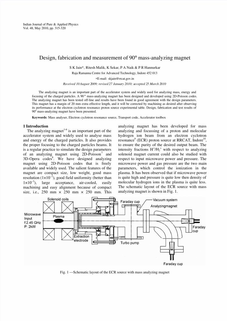
parameters, which control the ionization in theplasma. It has been observed that if microwave poweris quite high and pressure is quite low then density ofmolecular hydrogen ions in the plasma is quite less.The schematic layout of the ECR source with massanalyzing magnet is shown in Fig. 1.
Fig. 1 —Schematic layout of the ECR source with mass analyzing magnet

8/10/2019 IJPAP 48(5) 315-320
http://slidepdf.com/reader/full/ijpap-485-315-320 2/6
INDIAN J PURE & APPL PHYS, VOL 48, MAY 2010316
2 Mass Analyzing Magnet DesignThe design of mass analyzing magnet was done
using 2D-Poisson codes. We have chosen sector polewith rectangular yoke (C-shaped) type magnet 11 . The
C-shaped magnet is chosen because of simplicity indesign, easy access of vacuum chamber andfabrication, low machining and fabrication cost ascompared to sector and circular poles with sectoryoke. The design parameters of the mass-analyzingmagnet are presented in Table 1. To get the desiredfield configuration number of iteration have beendone. Here we compare the analysis of the twomodels 1 and 2. In model-1, we achieved the goodfield region as ±30 mm and central field at ~10 mmoff from the centre of the pole toward the back yokeand changing with magnet excitement. In model-2,
Table 1—The design parameters of the mass analyzing magnet
Magnet type Parameters
Bending angle 90 degreeGood field region ± 30 mmBending radius (central orbit) 120 mmDesign field 3000 gaussHomogeneity 1×10 −3 Pole gap height / width 26 mm / 112 mmPower supply 25 V, 15 A d.c.
the cut of 30 mm×10 mm at the pole near the top yokewas provided to remove the above problem. In this,we achieved the centre of magnet and pole centre atthe same point and good field region of ± 35 mm, andfield symmetry about the centre of magnet. The fieldprofiles for the model-1 and model-2 are shown inFig. 2.
The NI (ampere-turn) is calculated by, NI = B (T )×pole gap (meter)/(4* π×10 -7) assuming ironpermeability is infinite. The total NI for required fieldis 6210. Considering safety factor for saturation about10-15%, total NI chosen for coils is 7200. Thecalculated mass resolving power ( ∆ M / M ) usingstandard relation 11 of the magnet is about 1×10 −2. Thefocal length of the sector magnet is, f = −(1/ ρ) sin θ,and it is 120 mm (in present case). This magnet has
focussing effects in horizontal plane only and acts asdrift space in horizontal plane with focusing effects. Itis assumed that entrance and exit angles are perfectlysame. A small effect in vertical focussing effect canbe seen due to fringing field present at the entranceand exit of the magnet. In general practice the imagesuffers from aberrations due to higher order terms,particularly for marginal beams. Here we have tried tominimize the geometrical aberrations due to higherorder terms by incorporating multipole fieldcomponents in the magnet itself.
Fig. 2 —Field profile for (a) model-1 and (b) model-2
8/10/2019 IJPAP 48(5) 315-320
http://slidepdf.com/reader/full/ijpap-485-315-320 3/6
JAIN et al .: MASS-ANALYZING MAGNET 317
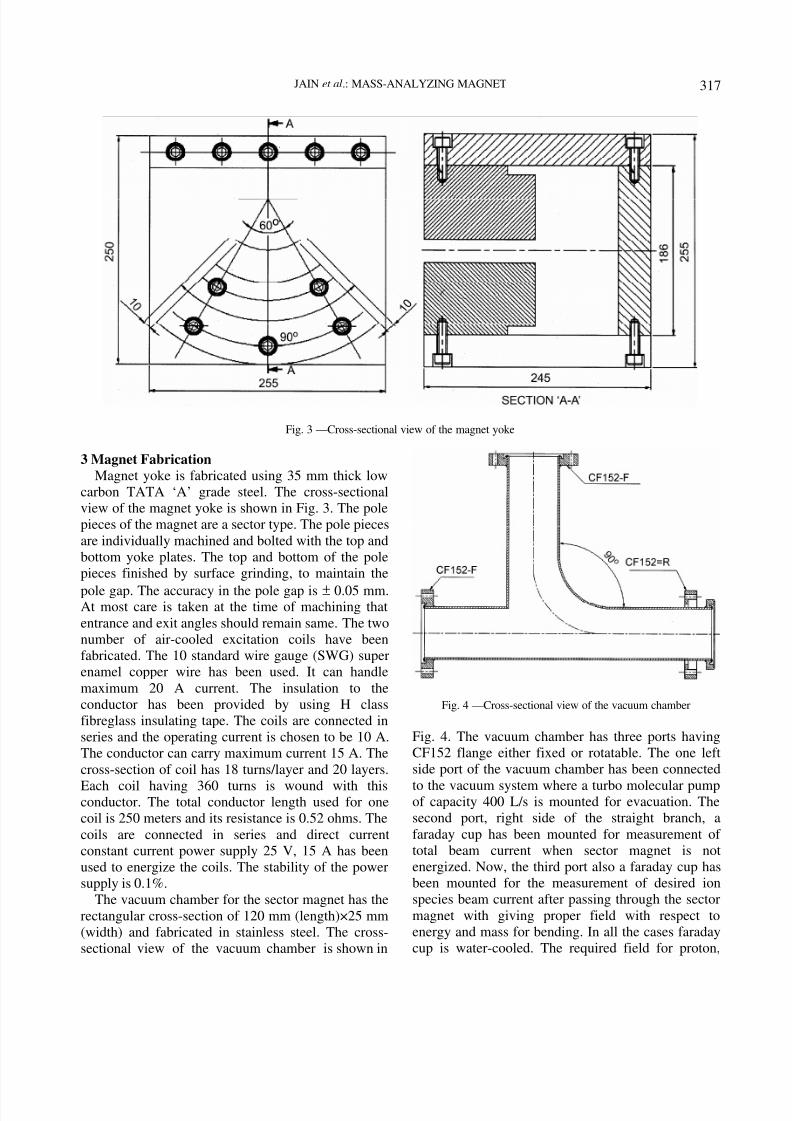
3 Magnet FabricationMagnet yoke is fabricated using 35 mm thick low
carbon TATA ‘A’ grade steel. The cross-sectionalview of the magnet yoke is shown in Fig. 3. The polepieces of the magnet are a sector type. The pole piecesare individually machined and bolted with the top andbottom yoke plates. The top and bottom of the polepieces finished by surface grinding, to maintain the
pole gap. The accuracy in the pole gap is ± 0.05 mm.At most care is taken at the time of machining thatentrance and exit angles should remain same. The twonumber of air-cooled excitation coils have beenfabricated. The 10 standard wire gauge (SWG) superenamel copper wire has been used. It can handlemaximum 20 A current. The insulation to theconductor has been provided by using H classfibreglass insulating tape. The coils are connected inseries and the operating current is chosen to be 10 A.The conductor can carry maximum current 15 A. Thecross-section of coil has 18 turns/layer and 20 layers.
Each coil having 360 turns is wound with thisconductor. The total conductor length used for onecoil is 250 meters and its resistance is 0.52 ohms. Thecoils are connected in series and direct current constant current power supply 25 V, 15 A has beenused to energize the coils. The stability of the powersupply is 0.1%.
The vacuum chamber for the sector magnet has therectangular cross-section of 120 mm (length)×25 mm(width) and fabricated in stainless steel. The cross-sectional view of the vacuum chamber is shown in
Fig. 4 —Cross-sectional view of the vacuum chamber
Fig. 4. The vacuum chamber has three ports havingCF152 flange either fixed or rotatable. The one leftside port of the vacuum chamber has been connected
to the vacuum system where a turbo molecular pumpof capacity 400 L/s is mounted for evacuation. Thesecond port, right side of the straight branch, afaraday cup has been mounted for measurement oftotal beam current when sector magnet is notenergized. Now, the third port also a faraday cup hasbeen mounted for the measurement of desired ionspecies beam current after passing through the sectormagnet with giving proper field with respect toenergy and mass for bending. In all the cases faradaycup is water-cooled. The required field for proton,
Fig. 3 —Cross-sectional view of the magnet yoke
8/10/2019 IJPAP 48(5) 315-320
http://slidepdf.com/reader/full/ijpap-485-315-320 4/6
INDIAN J PURE & APPL PHYS, VOL 48, MAY 2010318
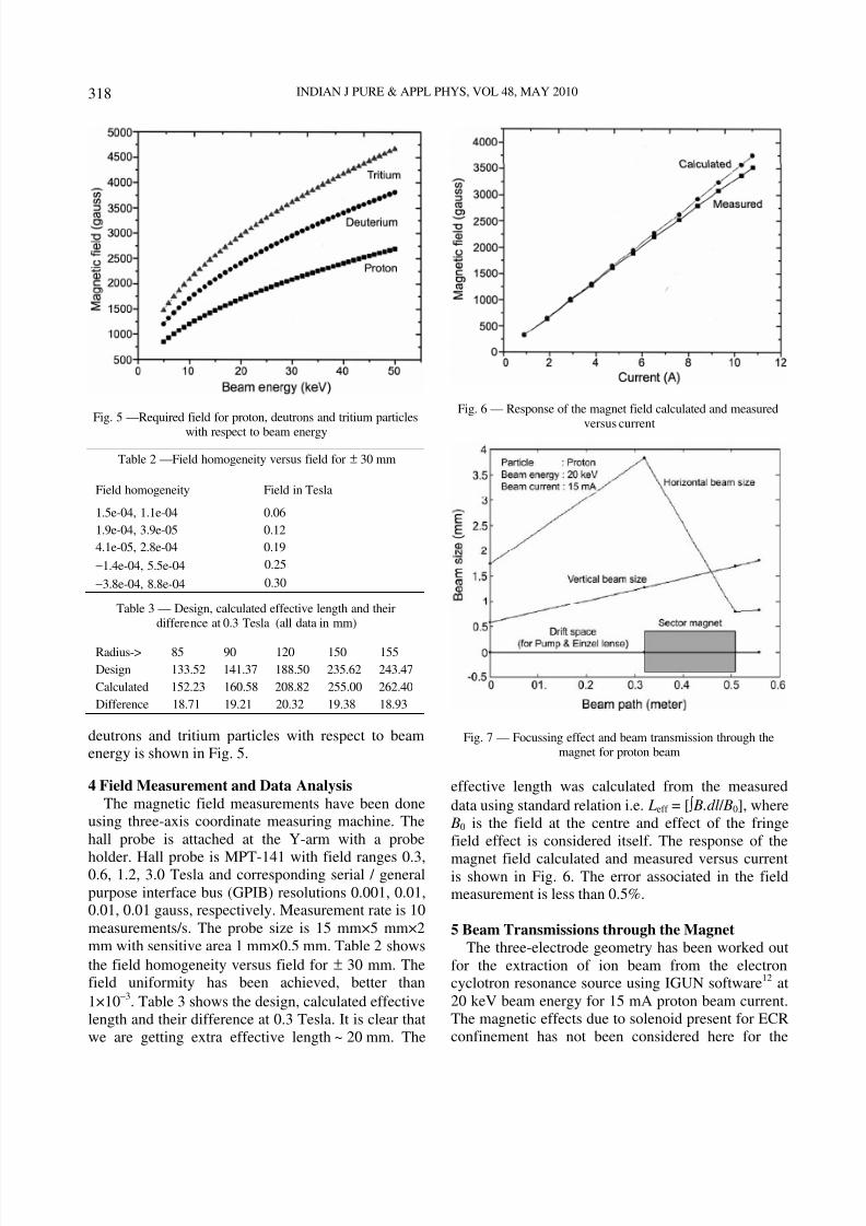
deutrons and tritium particles with respect to beamenergy is shown in Fig. 5.
4 Field Measurement and Data AnalysisThe magnetic field measurements have been done
using three-axis coordinate measuring machine. Thehall probe is attached at the Y-arm with a probe
holder. Hall probe is MPT-141 with field ranges 0.3,0.6, 1.2, 3.0 Tesla and corresponding serial / generalpurpose interface bus (GPIB) resolutions 0.001, 0.01,0.01, 0.01 gauss, respectively. Measurement rate is 10measurements/s. The probe size is 15 mm×5 mm×2mm with sensitive area 1 mm×0.5 mm. Table 2 showsthe field homogeneity versus field for ± 30 mm. Thefield uniformity has been achieved, better than1×10 −3. Table 3 shows the design, calculated effectivelength and their difference at 0.3 Tesla. It is clear thatwe are getting extra effective length ~ 20 mm. The
Fig. 6 — Response of the magnet field calculated and measured
versus current
Fig. 7 — Focussing effect and beam transmission through themagnet for proton beam
effective length was calculated from the measureddata using standard relation i.e. Leff = [ ∫ B.dl / B0], where
B0 is the field at the centre and effect of the fringefield effect is considered itself. The response of the
magnet field calculated and measured versus currentis shown in Fig. 6. The error associated in the fieldmeasurement is less than 0.5%.
5 Beam Transmissions through the MagnetThe three-electrode geometry has been worked out
for the extraction of ion beam from the electroncyclotron resonance source using IGUN software 12 at20 keV beam energy for 15 mA proton beam current.The magnetic effects due to solenoid present for ECRconfinement has not been considered here for the
Fig. 5 —Required field for proton, deutrons and tritium particleswith respect to beam energy
Table 2 —Field homogeneity versus field for ± 30 mm
Field homogeneity Field in Tesla
1.5e-04, 1.1e-04 0.061.9e-04, 3.9e-05 0.124.1e-05, 2.8e-04 0.19−1.4e-04, 5.5e-04 0.25
−3.8e-04, 8.8e-04 0.30
Table 3 — Design, calculated effective length and theirdifference at 0.3 Tesla (all data in mm)
Radius-> 85 90 120 150 155Design 133.52 141.37 188.50 235.62 243.47Calculated 152.23 160.58 208.82 255.00 262.40Difference 18.71 19.21 20.32 19.38 18.93
8/10/2019 IJPAP 48(5) 315-320
http://slidepdf.com/reader/full/ijpap-485-315-320 5/6
JAIN et al .: MASS-ANALYZING MAGNET 319
optimization of the electrode geometry using IGUN.The 275 mm distance from the plasma electrode wastreated as object plane for mass analyzing magnet.The twiss parameters at 275 mm down to the plasmaelectrode are beta ( βx = βy) 3.0067 m, alpha ( α x =
α y)−11.2680 rad and γ x= γ y can be calculated from γ =[(1+ α 2)/ β] for 20 keV proton beam energy. The rmsemittance 0.02788 mm-mrad has been achieved. Now,this beam has been passed through the sector magnetand beam transmission has been studied usingtransport 13 and accelerator toolbox 14. A drift spacebefore and after the sector magnet length 300 mm, 50mm has been added respectively in this simulation.The twiss parameters βx = 0.6548 m, βy = 28.8684 m,α x = −25.72 rad and α y = −35.04 rad have beenachieved. This beam has been matched. The focussingeffect and beam transmission through the magnet for
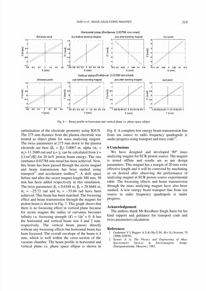
proton beam is shown in Fig. 7. This graph shows thatthere is no focussing effect in vertical plane becausefor sector magnet the radius of curvature becomesinfinity i.e. focussing strength ( K ) = 1/ ρ2 = 0. It hasthe horizontal and vertical beam size 4 and 2 mm,respectively. The vertical beam passes directlywithout any focussing effects but horizontal beam hasbeen focussed. The overall envelope of the beam is 4mm, which is well within the cross-section of thevacuum chamber. The beam profile in horizontal andvertical plane i.e. phase space ellipse is shown in
Fig. 8. A complete low energy beam transmission linefrom ion source to radio frequency quadrupole isunder progress using transport and trace code 15.
6 Conclusions
We have designed and developed 90 ° massanalyzing magnet for ECR proton source. The magnetis tested offline and results are as per designparameters. This magnet has a margin of 20 mm extraeffective length and it will be corrected by machiningas on desired after observing the performance ofanalyzing magnet at ECR proton source experimentaltable. The focussing effects and beam transmissionthrough the mass analyzing magnet have also beenstudied. A low energy beam transport line from ionsource to radio frequency quadrupole is underprogress.
AcknowledgementThe authors thank Mr Ravdheer Singh Saini for his
kind support and guidance for transport code andtwiss parameters calculation.
References1 Gushenets V I, Bugaev A S & Oks E M, Rev Sci Instrum, 79
(2008) 02B701.2 Sysoev A A, The Physics and Engineering of Mass
Spectrometry Devices & Electromagnetc Setups(Energoatomizdat, Moscow), 1983.
Fig. 8 — Beam profile in horizontal and vertical plane i.e. phase space ellipse

8/10/2019 IJPAP 48(5) 315-320
http://slidepdf.com/reader/full/ijpap-485-315-320 6/6
INDIAN J PURE & APPL PHYS, VOL 48, MAY 2010320
3 Friedrich L, Huttel E, Hentschel R & Tyrroff H, Proc of the11 th Int Workshop on ECR Ion Sources, May 1993,Groningen, 1993.
4 Henke D, Tyrroff H, Grotzschel R & Wirth H, Nucl Instr Meth B, 98 (1995) 528.
5 Henke D & Tyrroff H, Rev Sci Instrum, 67 (1996) 1070.6 Sun L T, Zhao H W, Zhang Z M, et al. , Rev Sci Instrum, 77
(2006) 03A319.7 2D POISSON Code (LANL Los Alamos, New Mexico),
86545.8 3D-Opera Code (Vector Fields Ltd, Oxford, U K),
www.vectorfields.co.uk.
9 Geller R, Electron Cyclotron Resonance Ion sourcs & ECR plasmas (Institute of Physics , London), 1966.
10 Jain S K, Akhilesh Jain, Hannurkar P R & Kotaiah S, Rev Sci Instrum, 78 (2007) 053301.
11 Livingood J J, The Optics of Dipole Magnets (Academic
press, New York & London), 1969.12 Becker R, IGUN 6.004, Germany13 Brown K L et al. , Yellow Reports , CERN 73-16 (1973),
CERN 80-04(1980), SLAC-Pub 95-06 (1995).14 Terebilo A, SLAC-Pub 8732 (2001), http//www.ssrl.slac.
stanford.edu/at15 Crandall K R, Trace-3D Documentation (Los Alamos Report
LA-UR-97-886) 1997.