Embed Size (px)
Citation preview
IJREAT International Journal of Research in Engineering & Advanced Technology, Volume 3, Issue 1, Feb-Mar, 2015
ISSN: 2320 – 8791 (Impact Factor: 1.479)
www.ijreat.org
www.ijreat.org Published by: PIONEER RESEARCH & DEVELOPMENT GROUP (www.prdg.org) 254
Fuzzy Logic Based Dynamic Controller For Three Phase Brushless
DC Motor
R.Rajalakshmi, Mrs.T.Umamaheswari, Dr.S.Vijayarajan, Mr.K.Kannan
Department of Electrical and Electronics Engineering
RATNAVELU SUBRAMANIAM COLLEGE OF ENGINEERING AND TECHNOLOGIES, DINDIGUL, INDIA Abstract- This paper introduce the fuzzy logic controller for
brushless direct current (BLDC) permanent magnet motor
drives. Entry of the fuzzy logic controller is developed using
MATLAB Fuzzy-Logic Toolbox and then inserted into the
Simulink model. The dynamic Parameters of the brushless DC
motor like speed, torque, current and voltage of the inverter
components are observed and analyzed using the developed
MATLAB model. In order to Check the effectiveness of the
controller, the simulation outputs are compared with
TMS320F2808 DSP experimental outputs. The simulation and
experimental outputs show that the brushless direct current
motor (BLDC) is successfully and efficiently controlled by the
Fuzzy logic controller. Index Terms –BLDC motor,MATLAB,DSP Processor
I. INTRODUCTION BLDC motor is widely used in many sectors
nowadays from the very critical implementations to a large scale industrial and automotive applications. It is preferable to use BLDC motor over the conventional DC motor with brushes because of its lifespan, high efficiency, and low maintenance. However it has some drawbacks over the advantages. A controller must present with BLDC motor and it is rather complex to drive BLDC motor compared to the conventional one. In a BLDC motor, the electromagnets do not move; instead, the permanent magnets rotate and the armature remains static. This gets around the problem of how to transfer current to a moving armature. In order to do this, the brush system commutator assembly is replaced by an electronic controller. The controller performs the same power distribution found in a brushed DC motor, but using a solid-state circuit rather than a commutator brush system.
II. OPERATION OF BLDC MOTOR The underlying principles for the working of a BLDC
motor are the same as for a Brushed DC motor internal shaft position feedback. In case of a Brushed DC motor, feedback is implemented using a mechanical
commutator and brushes. With a in BLDC motor, it is achieved using multiple feedback sensors. The most commonly used sensors are hall sensors. A. Hall Sensors
A Hall Effect sensor is a transducer that varies its output voltage in response to a magnetic field. Hall Effect sensors are used for proximity switching, positioning, speed detection, and current sensing applications.
In its simplest form, the sensor operates as an analogue transducer, directly returning a voltage. With a known magnetic field, its distance from the Hall plate can be determined. Using groups of sensors, the relative position of the magnet can be deduced. B. Digital Controller
The modulation control of BLDC motors will be efficient and cost effective .The digital control Of the four quadrant operation of the three phase BLDC motors achieved with PIC microcontroller The reference speed and the duty cycle can be fed in to the controller.The closed loop control much achieved with PI controller.
III. PROJECT DESCRIPTION A.
PROPOSED DESCRIPTION
B r u s h l e s s DC motor has a rotor with permanent mag- nets and a stator with windings. It is motor turned inside out. The brushes and commutator have been eliminated and the windings are connected to the control electronics. The control electronics replace the function of the commutator and energize the proper winding. The motor has less inertia, therefore easier to start and stop. BLDC motors are potentially cleaner, faster, more efficient, less noisy and more reliable.
IJREAT International Journal of Research in Engineering & Advanced Technology, Volume 3, Issue 1, Feb
ISSN: 2320 – 8791 (Impact Factor: 1.479
www.ijreat.org
Published by: PIONEER RESEARCH & DEVELOPMENT GROUP (www.prdg.org)
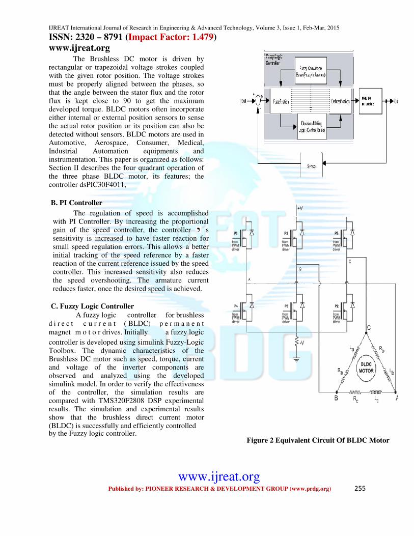
The Brushless DC motor is driven by
rectangular or trapezoidal voltage strokes coupled with the given rotor position. The voltage strokes must be properly aligned between the phases, so that the angle between the stator flux and the rotor flux is kept close to 90 to get the maximum developed torque. BLDC motors often incorporate either internal or external position sensors to sense the actual rotor position or its position can also be detected without sensors. BLDC motors are used in Automotive, Aerospace, Consumer, Industrial Automation equipments and instrumentation. This paper is organized as follows: Section II describes the four quadrant operation of the three phase BLDC motor, its features; the controller dsPIC30F4011,
B. PI Controller
The regulation of speed is accomplished with PI Controller. By increasing the proportional gain of the speed controller, the controller sensitivity is increased to have faster reaction for small speed regulation errors. This allows a better initial tracking of the speed reference by a faster reaction of the current reference issued by the speed controller. This increased sensitivity also reduces the speed overshooting. The armature current reduces faster, once the desired speed is achieved.
C. Fuzzy Logic Controller
A fuzzy logic controller
d i r e c t c u r r e n t ( BLDC) magnet m o t o r drives. Initially controller is developed using simulink FuzzyToolbox. The dynamic characteristics of theBrushless DC motor such as speed, torque, current and voltage of the inverter components are observed and analyzed using the developed simulink model. In order to verify the effectiveness of the controller, the simulation results are compared with TMS320F2808 DSP experimental results. The simulation and experimental results show that the brushless direct current motor (BLDC) is successfully and efficiently controlledby the Fuzzy logic controller.
IJREAT International Journal of Research in Engineering & Advanced Technology, Volume 3, Issue 1, Feb
Impact Factor: 1.479)
www.ijreat.org Published by: PIONEER RESEARCH & DEVELOPMENT GROUP (www.prdg.org)
ess DC motor is driven by rectangular or trapezoidal voltage strokes coupled with the given rotor position. The voltage strokes must be properly aligned between the phases, so that the angle between the stator flux and the rotor
get the maximum developed torque. BLDC motors often incorporate either internal or external position sensors to sense the actual rotor position or its position can also be detected without sensors. BLDC motors are used in Automotive, Aerospace, Consumer, Medical, Industrial Automation equipments and instrumentation. This paper is organized as follows: Section II describes the four quadrant operation of the three phase BLDC motor, its features; the
The regulation of speed is accomplished with PI Controller. By increasing the proportional gain of the speed controller, the controller s sensitivity is increased to have faster reaction for small speed regulation errors. This allows a better
cking of the speed reference by a faster reaction of the current reference issued by the speed controller. This increased sensitivity also reduces the speed overshooting. The armature current reduces faster, once the desired speed is achieved.
controller for brushless
p e r m a n e n t
a fuzzy logic
controller is developed using simulink Fuzzy-Logic Toolbox. The dynamic characteristics of the Brushless DC motor such as speed, torque, current and voltage of the inverter components are observed and analyzed using the developed simulink model. In order to verify the effectiveness of the controller, the simulation results are
2808 DSP experimental results. The simulation and experimental results show that the brushless direct current motor (BLDC) is successfully and efficiently controlled
Figure 2 Equivalent Circuit Of BLDC Motor
IJREAT International Journal of Research in Engineering & Advanced Technology, Volume 3, Issue 1, Feb-Mar, 2015
Published by: PIONEER RESEARCH & DEVELOPMENT GROUP (www.prdg.org) 255
Figure 2 Equivalent Circuit Of BLDC Motor
IJREAT International Journal of Research in Engineering & Advanced Technology, Volume 3, Issue 1, Feb-Mar, 2015
ISSN: 2320 – 8791 (Impact Factor: 1.479)
www.ijreat.org
www.ijreat.org Published by: PIONEER RESEARCH & DEVELOPMENT GROUP (www.prdg.org) 256
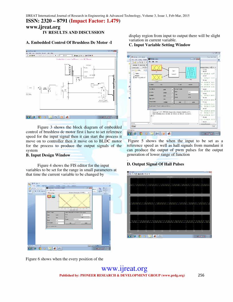
IV RESULTS AND DISCUSSION A. Embedded Control Of Brushless Dc Motor -I
Figure 3 shows the block diagram of embedded control of brushless dc motor first i have to set reference speed for the input signal then it can start the process it move on to controller then it move on to BLDC motor for the process to produce the output signals of the system B. Input Design Window
Figure 4 shows the FIS editor for the input
variables to be set for the range in small parameters at that time the current variable to be changed by
display region from input to output there will be slight variation in current variable. C. Input Variable Setting Window
Figure 5 shows the when the input to be set as a
reference speed as well as hall signals from mamdani it can produce the output of pwm pulses for the output generation of lower range of function .
D. Output Signal Of Hall Pulses
Figure 6 shows when the every position of the
IJREAT International Journal of Research in Engineering & Advanced Technology, Volume 3, Issue 1, Feb
ISSN: 2320 – 8791 (Impact Factor: 1.479
www.ijreat.org
Published by: PIONEER RESEARCH & DEVELOPMENT GROUP (www.prdg.org)
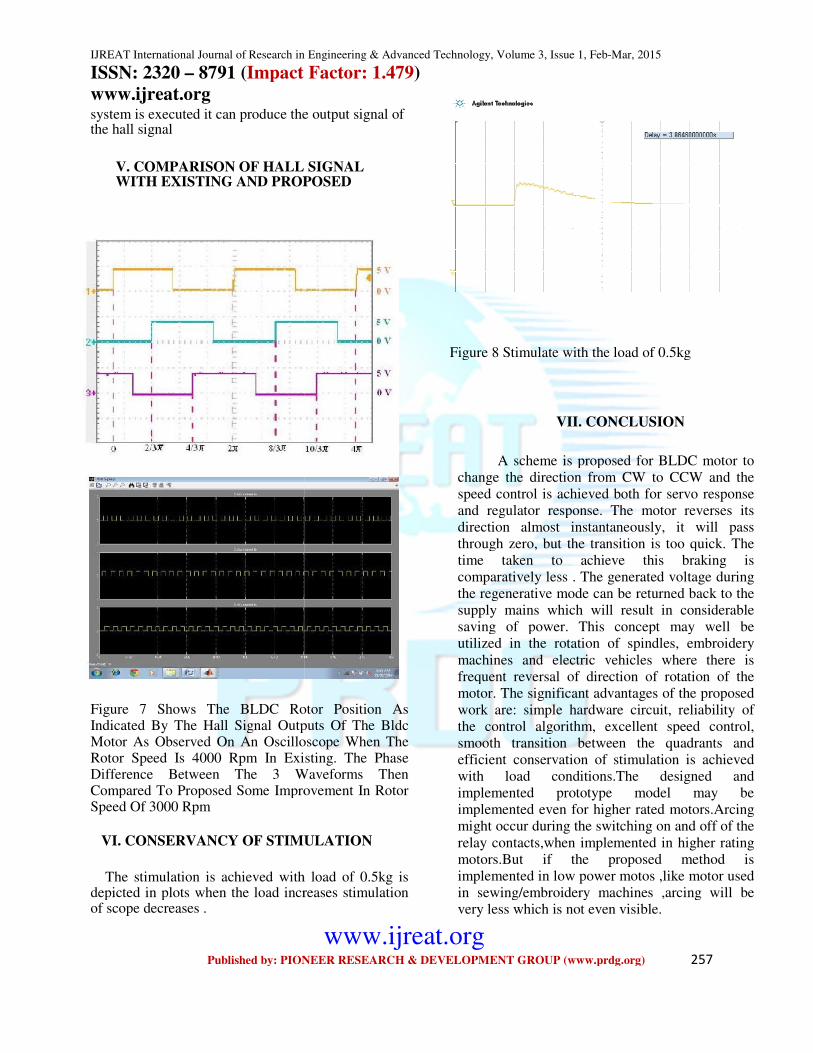
system is executed it can produce the output signal of the hall signal
V. COMPARISON OF HALL SIGNAL WITH EXISTING AND PROPOSED
Figure 7 Shows The BLDC Rotor Position As Indicated By The Hall Signal Outputs Of The Bldc Motor As Observed On An Oscilloscope When The Rotor Speed Is 4000 Rpm In Existing. The Phase Difference Between The 3 Waveforms Then Compared To Proposed Some Improvement In Rotor Speed Of 3000 Rpm
VI. CONSERVANCY OF STIMULATION
The stimulation is achieved with load of 0.5kg is
depicted in plots when the load increases stimulation of scope decreases .
IJREAT International Journal of Research in Engineering & Advanced Technology, Volume 3, Issue 1, Feb-
Impact Factor: 1.479)
www.ijreat.org Published by: PIONEER RESEARCH & DEVELOPMENT GROUP (www.prdg.org)
system is executed it can produce the output signal of
V. COMPARISON OF HALL SIGNAL WITH EXISTING AND PROPOSED
Figure 7 Shows The BLDC Rotor Position As The Hall Signal Outputs Of The Bldc
Motor As Observed On An Oscilloscope When The Rotor Speed Is 4000 Rpm In Existing. The Phase Difference Between The 3 Waveforms Then Compared To Proposed Some Improvement In Rotor
STIMULATION
The stimulation is achieved with load of 0.5kg is depicted in plots when the load increases stimulation
Figure 8 Stimulate with the load of 0.5kg
VII. CONCLUSION
A scheme is proposed for BLDC motor to
change the direction from CW to CCW and the speed control is achieved both for servo response and regulator response. The motor reverses its direction almost instantaneously, it will pass through zero, but the transition is too quick. The time taken to achieve this braking is comparatively less . The generated voltage during the regenerative mode can be returned back to the supply mains which will result in considerable saving of power. This concept may well be utilized in the rotation of spindles, embroide
machines and electric vehicles where there is frequent reversal of direction of rotation of the motor. The significant advantages of the proposed work are: simple hardware circuit, reliability of the control algorithm, excellent speed control, smooth transition between the quadrants and efficient conservation of stimulation is achieved with load conditions.The designed and implemented prototype model may be implemented even for higher rated motors.Arcing might occur during the switching on and off of the
relay contacts,when implemented in higher rating motors.But if the proposed method is implemented in low power motos ,like motor used in sewing/embroidery machines ,arcing will be very less which is not even visible.
-Mar, 2015
Published by: PIONEER RESEARCH & DEVELOPMENT GROUP (www.prdg.org) 257
Figure 8 Stimulate with the load of 0.5kg
VII. CONCLUSION
A scheme is proposed for BLDC motor to change the direction from CW to CCW and the speed control is achieved both for servo response and regulator response. The motor reverses its direction almost instantaneously, it will pass through zero, but the transition is too quick. The
ieve this braking is comparatively less . The generated voltage during the regenerative mode can be returned back to the supply mains which will result in considerable saving of power. This concept may well be utilized in the rotation of spindles, embroidery
machines and electric vehicles where there is frequent reversal of direction of rotation of the motor. The significant advantages of the proposed work are: simple hardware circuit, reliability of the control algorithm, excellent speed control,
ansition between the quadrants and efficient conservation of stimulation is achieved with load conditions.The designed and implemented prototype model may be implemented even for higher rated motors.Arcing might occur during the switching on and off of the
relay contacts,when implemented in higher rating motors.But if the proposed method is implemented in low power motos ,like motor used in sewing/embroidery machines ,arcing will be very less which is not even visible.
IJREAT International Journal of Research in Engineering & Advanced Technology, Volume 3, Issue 1, Feb-Mar, 2015
ISSN: 2320 – 8791 (Impact Factor: 1.479)
www.ijreat.org
www.ijreat.org Published by: PIONEER RESEARCH & DEVELOPMENT GROUP (www.prdg.org) 258
REFERENCES
[1] Afjei,O. Hashemipour, M.A. Saati, and M. M.Nezamabadi,
“A new hybrid brushless DC motor/generator without permanent magnet,” IJE Trans. B: Appl., vol. 20, no. 1, pp. 77 - 86, Apr. 2007.
[2] A. Sathyan, N. Milivojevic, and A. Emadi, “A low- cost digital control scheme for brushless DC motor drives in domestic applications”, in Proc. Int. Electric Machines Drives Conf., 2009, pp. 250 - 280 .
[3] A.. Sathyan, N. Milivojevic, Y.-J. Lee, M. Krishnamurthy, And
A.Emadi,”An FPGA-based novel digital PWM control Scheme
for BLDCmotordrives”IEEETransInd.Electron.,vol-56, no. 8,
pp.3040 - 3049, Aug. 2009.
[4] C. S.Joice and Dr. S. R Paranjothi,“ Simulation of closed loop control of four quadrant operation in three phase-
brushless DC .motor MATLAB/simu link”in proc ICPCES- , 2010, pp. 259 - 263.
[5] C. Xia, Z. Li, and T. Shi, “A control strategy four- switch
three- phase brushless DC motor using single current sen -
sensor “IEEE Trans. Ind. Electron., vol.56,no.6,pp. 2058 -
2066, June 2009.
[6] J. Li, H. Zhang, Q. Wan, J. Liu, and H. Zhang, “A novel charging control for flywheel energy storage system based on BLDC motor “in Proc. Asia Pacific Power and Energy Engineering Conference (APPEEC), China, Mar. 2010 pp. 1 - 3.
[7] L. N. Elevich, “ 3-phase BLDC motor control with hall controllers,” AN1916, Application Note, Rev.2.0, 11/-2005.
[8] C. S. Joice, Dr. S. R. Paranjothi, and Dr. V. J.S. Kumar,
“ Practical implementation of four quadrant operation of three phase Brushless DC motor using dsPIC “ in Proc. IConRAEeCE 2011, pp. 91- 94, IEEE.
[9] V. S. Pola, and K. P. Vittal, “ Simulation of four quadrant
operation& speed control of BLDC motor on
MATLAB/SIMULINK ” in Proc. IEEE Region 10 conf- erence, 2008, pp. 1–6.
[10] M.-F.Tsai, T. PhuQuy, B.-F. Wu, and C.-S. Tseng,
“ Model construction and verification of a BLDC motor
Using MATLAB/SIMULINK and FPGA control,” in Proc 6th IEEE Conf. Ind. Electron. Appl., Beijing, 2011, pp.1797–1802.