Embed Size (px)
Citation preview

IJSRD || National Conference on Recent Trends & Innovations in Mechanical Engineering || April 2016
ISSN(online): 2321-0613
©IJSRD 2016 Published by IJSRD 194
Friction Stir Welding (FSW) Simulation using FEA
Techniques-Parametric Study using Ansys APDL
T.Pavan Kumar1 Madhu Anupoju2 Ramanjaneya Reddy Munnangi3 Dr.Prabhakar Reddy4
1,4Assosiate Professor 2,3Professor Student 1,2,3Department of Mechanical Engineering
1,2,3Nalla Narasimha Reddy Education Society’s Group of Institutions 4CBIT,Hyderabad
Abstract— This thesis research implemented anewthermo- mechanical model of friction stir welding process created using
ANSYS APDL commands using FEA techniques. Under this thesisseveral characteristics of FSW are studied, including tool-
workpiece surface interaction, heat generation due to friction during the operating conditions of the FSW process, plastic
deformation and plastic heat generation due to the non-linear nature of the materials used in finite element analysis. In this
project a nonlinear direct coupled-field analysis is performed, as thermal and mechanical behaviours are mutually dependent
and coupled together during the FSW process. As an initial step, the thermo mechanical model developed by Zhu and Chao
for friction stir welding of 304L stainless steel was modelled using ANSYS APDL. ANSYS APDL macro is created in such a
way that it can be used for multiple design variants and load parameters in order to perform the FSW study for multiple
design variants. The developed model was then used to conduct parametric studies to understand the effect of various input
parameters like total rate of heat input, welding speed and clamping location on temperature distribution and residual stress in
the work piece. With the data arrived from the simulated models, various observations are made even with minor
modifications in the input parameters. In this project a transient thermos mechanical analysis is performed using coupled field
elements for different tool diameters and different sizes of the base plates which needs to be welded together using FSW.In
this project FSW process is studied in various stages DWELL, PLUNGE and TRAVERSE by solving the finite element
model in separate load cases. To avail the plastic heat bi-linear isotropic material properties are used. The salient observations
from this project are t: 1. heat input is mainly constrained by the lower bound of the temperature for making good welds;
Clamping closer to the weld is better than away from the weld in terms of lowering the peak residual stresses. Moreover, the
nonlinear models resulted in a realistic solution than the linear models when wide temperature range was used at the same
time as the simulation process is highly non-linear so many convergence issues will be raised. In this project bonding
temperature is considered at 10000 C.
Key words: Parametric Study, Ansys APDL
I. INTRODUCTION
Friction Stir Welding (FSW) is a revolutionary solid state welding technique invented at The Welding Institute (TWI) in 1991
[1]. The FSW process operates below the solidus temperature of the metals being joined and hence no melting takes place
during the process. This process is a derivative of the conventional friction welding and is being used to produce continuous
welded seams for plate fabrication [2]. Since its invention in 1991, continuous attempts have been made by researchers to
understand, use and improve this process. Friction Stir Welding is a hot-shear joining process in which a non-consumable,
rotating tool plunges into a rigidly clamped work piece and moves along the joint to be welded [3]. The cylindrical rotating
tool used in FSW has a profiled threaded or unthreaded probe of length less than the weld depth, extruding from the tool
shoulder. The operating principle of FSW process is presented in figure 1.1.
Fig. 1.1: Friction Stir Welding Operation Principle
Friction Stir Welding (FSW) Simulation using FEA Techniques-Parametric Study using Ansys APDL
(IJSRD/Conf/RTIME/2016/034)
195
II. FINITE ELEMENT MODEL OF FSW
The Finite Element Method (FEM) offers a way to solve complex continuum problems by subdividing it into a series of
simple interrelated problems (mesh generation). FEM is most commonly used in numerical analysis for obtaining
approximate solutions to wide variety of engineering problems. In the present study, a commercial general purpose finite
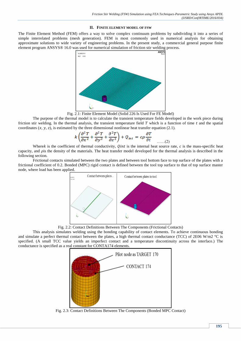
element program ANSYS® 16.0 was used for numerical simulation of friction stir welding process.
Fig. 2.1: Finite Element Model (Solid 226 Is Used For FE Model)
The purpose of the thermal model is to calculate the transient temperature fields developed in the work piece during
friction stir welding. In the thermal analysis, the transient temperature field 𝑇 which is a function of time 𝑡 and the spatial
coordinates (𝑥, 𝑦, 𝑧), is estimated by the three dimensional nonlinear heat transfer equation (2.1).
……(2)
Where𝑘 is the coefficient of thermal conductivity, 𝑄𝑖𝑛𝑡 is the internal heat source rate, 𝑐 is the mass-specific heat
capacity, and 𝜌is the density of the materials. The heat transfer model developed for the thermal analysis is described in the
following section.
Frictional contacts simulated between the two plates and between tool bottom face to top surface of the plates with a
frictional coefficient of 0.2. Bonded (MPC) rigid contact is defined between the tool top surface to that of top surface master
node, where load has been applied.
Fig. 2.2: Contact Definitions Between The Components (Frictional Contacts)
This analysis simulates welding using the bonding capability of contact elements. To achieve continuous bonding
and simulate a perfect thermal contact between the plates, a high thermal contact conductance (TCC) of 2E06 W/m2 °C is
specified. (A small TCC value yields an imperfect contact and a temperature discontinuity across the interface.) The
conductance is specified as a real constant for CONTA174 elements.
Fig. 2.3: Contact Definitions Between The Components (Bonded MPC Contact)

Friction Stir Welding (FSW) Simulation using FEA Techniques-Parametric Study using Ansys APDL
(IJSRD/Conf/RTIME/2016/034)
196
A multipoint constraint (MPC) algorithm with contact surface behaviour defined as bonded always is used to
constrain the contact nodes to the rigid body motion defined by the pilot node as shown in figure 2.3.
A. Boundary Conditions
Fig. 2.4: Thermal Boundary Conditions
Fig. 2.5: Mechanical Boundary Conditions
The following boundary conditions are utilized for the mechanical analysis:
The work piece is constrained of vertical motion at the bottom surface.
The work piece is fixed through clamping by 200 mm long L-shaped steel strip (25.4 mm x 25.4 mm x 6.35 mm) on
each plate. Totally rigid boundary conditions are applied at these clamping locations.
1) Validation Of Thermo- Mechanical Model Of Friction Stir Welding (Dwell And Plunge)
For validating the thermo mechanical model developed using ANSYS®16 the temperature dependent material properties and
loads are applied on the model have been considered from Zhu and Chao parameters used for FSW process [2]. In this project
we were discussing the results in 1st 2 stages of FSW, namely DWELL and PLUNGE. As the simulation is very high end
non-linear problem the analysis is carried out upto 7.5 sec total time, where DWELL process is upto 1sec, Plunge is upto 6.5
sec duration, after that TRAVERSE is simulated upto 7.5 sec time. Following are the observations and result plots using
transient thermos-mechanical analysis of the friction stir welding process under the given loads and boundary conditions.
2) Emperature Responses, Displacements and Stresses Observed at Each Stage of FSW
The overall temperature distributions on the work piece are illustrated in the below graph obtained over a simulation time
period of 7.5 sec.
Fig. 3.1: Temperature Distribution for The Simulation Time Of 7.5sec

Friction Stir Welding (FSW) Simulation using FEA Techniques-Parametric Study using Ansys APDL
(IJSRD/Conf/RTIME/2016/034)
197
3) Following Results Are Documented At The End Of Simulation Time 1 Sec (Dwell Process)
Fig. 3.2: Temperature Distribution At The End Of Dwell Process (T=1 Sec)
Fig. 3.3: Directional Displaceat the End of Dwell Process (T=1 Sec)
Fig. 3.4: Total Displaceat the End of Dwell Process (T=1 Sec)
The temperature fields obtained from the thermal model are used as input for the mechanical simulation for calculation of
residual stresses. The primary residual stresses in FSW were observed in the longitudinal direction. The maximum residual
stresses observed at the end of dwell process are listed below.

Friction Stir Welding (FSW) Simulation using FEA Techniques-Parametric Study using Ansys APDL
(IJSRD/Conf/RTIME/2016/034)
198
Fig. 3.5: Von-Mises Stressesat The End Of Dwell Process (T=1 Sec)
Fig. 3.6: Frictional Stressesat The End Of Dwell Process (T=1 Sec)
4) Following Results Are Documented At The End Of Simulation Time 6.5 Sec (Plunge Process)
Fig. 3.7: Temperature distribution at the end of plunge process (t=6.5 sec)

Friction Stir Welding (FSW) Simulation using FEA Techniques-Parametric Study using Ansys APDL
(IJSRD/Conf/RTIME/2016/034)
199
Fig. 3.8: Total Displacementat The End Of Plunge Process (T=6.5 Sec)
Fig. 3.9: Directional Displacementat The End Of Plunge Process (T=6.5 Sec)
Fig. 3.10: Von-Mises Stressesat The End Of Plunge Process (T=6.5 Sec)

Friction Stir Welding (FSW) Simulation using FEA Techniques-Parametric Study using Ansys APDL
(IJSRD/Conf/RTIME/2016/034)
200
Fig. 3.11: Frictional stressesat the end of plunge process (t=6.5 sec)
5) Following Results Are Documented At The End Of Simulation Time 7.3 Sec (Traverse Process)
Fig. 3.12: Temperature Distribution At The End Of Traverse Process (T=7.32 Sec)
Fig. 3.13: Total Displacementat The End Of Traverse Process (T=7.32 Sec)

Friction Stir Welding (FSW) Simulation using FEA Techniques-Parametric Study using Ansys APDL
(IJSRD/Conf/RTIME/2016/034)
201
Fig. 3.14: Directional displacementat the end of traverse process (t=7.32 sec)
Fig. 3.15: Von-Mises Stressesat The End Of Traverse Process (T=7.32 Sec)
Fig. 3.16: Frictional Stressesat The End Of Traverse Process (T=7.32 Sec)

Friction Stir Welding (FSW) Simulation using FEA Techniques-Parametric Study using Ansys APDL
(IJSRD/Conf/RTIME/2016/034)
202
Fig. 3.17: Temperature Distribution Across The Thickness Of The Plates (T=7.32 Sec)
Fig. 3.18: Variation Of Transient Temperature - Comparison Of Simulated Results
Fig. 3.19: Variation of The Von-Mises Stresses Along The Traverse Direction At Mid-Section
III. FRICTION AND PLASTIC HEAT GENERATION RATE CALCULATION USING FEA
Friction and plastic deformation generate heat during the FSW process. Calculation of frictional and plastic heat generation is
performed. The generation of heat due to friction begins in the second load step (plunge process).
A. Frictional Heat Generation Rate
The CONTA174 element's FDDIS (SMISC item) output option is used to calculate frictional heat generation on the
workpiece. This option gives the frictional energy dissipation per unit area for an element. After multiplying this value with
the corresponding element area, the friction heat-generation rate for an element is calculated. By summing the values from
each CONTA174 element of the workpiece, the total frictional heat generation rate is calculated for a given time.

Friction Stir Welding (FSW) Simulation using FEA Techniques-Parametric Study using Ansys APDL
(IJSRD/Conf/RTIME/2016/034)
203
It is possible to calculate the total frictional heat-generation rate at each time-step (ETABLE option in ANSYS). The
following figure shows the plot of total frictional heat generation rate on the workpiece with time:
Fig. 4.1: Total Frictional Heat Rate With Variation In Time Upto 7.32 Sec
B. Total Plastic Heat Generation Rate
A similar calculation is performed to check the heat generation from plastic deformation on the workpiece. The SOLID226
element's output option PHEAT (NMISC, 5) gives the plastic heat generation rate per unit volume. After multiplying this
value with the corresponding element volume, the plastic heat generation rate for an element is calculated. By summing the
values from each element (SOLID226) of the workpiece, the total plastic heat generation rate is calculated for a particular
time.
It is possible to calculate the total frictional heat generation rate at each time-step (ETABLE). The following figure
shows the plot of the total plastic heat-generation rate with time.
Fig. 4.2: Total plastic heat generation rate with variation in time upto 7.32 sec
IV. OBSERVATIONS AND RECOMMENDATIONS FOR FUTURE WORK
A. Key Observations from The FEA
FSW is a coupled-field (structural-thermal) process. The temperature field affects the stress distribution during the
entire process. Also, heat generated in structural deformation affects the temperature field. The direct method of
coupling is recommended for such processes.
Friction and plastic deformation generate heat during the FSW process. Calculation of frictional and plastic heat
generation is performed. The generation of heat due to friction begins in the second load step (plunge process).
This method involves just one analysis that uses a coupled-field element containing all necessary degrees of
freedom. Direct coupling is advantageous when the coupled-field interaction involves strongly-coupled physics or is
highly nonlinear.
As we have implemented the parametric study using ANSYS APDL commands, different design variants can be
created parallel and the same can be simulated.

Friction Stir Welding (FSW) Simulation using FEA Techniques-Parametric Study using Ansys APDL
(IJSRD/Conf/RTIME/2016/034)
204
A nonlinear transient analysis is preferable for simulations where the objective is to study the transient temperature
and transient heat transfer.
The contact between the two plates must be nearly perfect to maintain temperature continuity. For a perfect thermal
contact, specify a high thermal contact conductance (TCC) coefficient between workpiece plates. A high coefficient
results in temperature continuity across the interface.
Convergence at the second and third load steps is difficult to achieve. The depth of penetration of the tool on the
workpiece (uz), rotational speed of the tool (rotz), and time-step size play crucial roles in the convergence of the
second load step.
V. FUTURE WORK
For future work, experimental investigations need to be carried out to verify the numerical simulations obtained in
this thesis.
The process variables used in this study were limited to responses, maximum temperature and residual stress and the
following input variables: heat input, weld speed, and clamping location.
The materials to be welded are considered identical in this study. But the simulation can be extended to simulate the
FSW process for dissimilar materials also.
Similar studies can be extended to other variants of friction stir welding processes such as laser-assisted friction stir
welding process, or the welding of dissimilar materials that will be technically more challenging due to the
differences in material properties.
In this thesis we considered simplified model of the tool without pin, but with good exposure and availability of the
high end software’s dynamic response of the FSW can be simulated through FEA techniques.
More comprehensive thermal-material-mechanical models could also be considered for optimization.
REFERENCES
[1] Thomas, W.M., Nicholas, E.D., Needham, J.C., Murch, M.G., Temple-Smith, P., and Dawes, C.J., Friction-stir butt
welding, GB Patent No. 9125978.8, International patent application No. PCT/GB92/02203, (1991).
[2] Zhu, X. K., and Y. J. Chao. “Numerical Simulation of Transient Temperature and Residual Stresses in Friction Stir
Welding of 304L Stainless Steel.” Journal of Materials Processing Technology.
[3] Ansys 16.0
[4] Chao, Y.J., X. Qi, and W. Tang. “Heat Transfer in Friction Stir Welding - Experimental and Numerical Studies.” Journal
of Manufacturing Science and Engineering-Transactions of the ASME.
[5] Sorensen, C.D., and T. W. Nelson. “Friction Stir Welding of Ferrous and Nickel Alloys.” Friction Stir Welding and
Processing. Ed. M. W. Mahoney and R. S. Mishra. Materials Park: ASM International, 2007.
[6] Nandan, R., DebRoy, T., and Bhadeshia, H., Recent advances in friction-stir welding - Process, weldment structure and
properties. Progress in Materials Science, 2008. 53(6): p. 980-1023.
[7] Lienert, T.J., Stellwag, W.L., Grimmett, B.B., and Warke, R.W., Friction stir welding studies on mild steel - Process
results, microstructures, and mechanical properties are reported. Welding Journal, 2003. 82(1): p. 1S-9S.
[8] Zettler, R., Donath, T., dos Santos, J.F., Beckman, F., and Lohwasser, D., Validation of marker material flow in 4mm
thick frictionstir welded Al2024-T351 through computer microtomography and dedicated metallographic techniques.
Advanced Engineering Materials, 2006. 8(6): p. 487-490.