Embed Size (px)
Citation preview
XIV Convegno SIRR – Trieste, 24-27 giugno 2008Giuliana Tromba1
Il progetto di mammografia clinica
con luce di sincrotrone:
aspetti fisici e dosimetrici
Giuliana TrombaSincrotrone Trieste
per la Collaborazione SYRMEP
XIV Convegno SIRR – Trieste, 24-27 giugno 2008Giuliana Tromba2
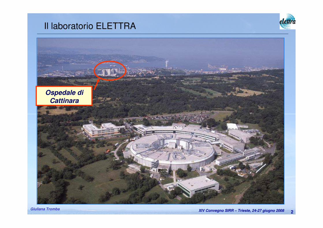
Ospedale di
Cattinara
Il laboratorio ELETTRA
XIV Convegno SIRR – Trieste, 24-27 giugno 2008Giuliana Tromba3
Sommario
� I vantaggi della luce di sincrotrone
� La linea di luce SYRMEP
� Il progetto di mammografia clinica con luce di sincrotrone
� Le problematiche di sicurezza e radioprotezione per la paziente e gli operatori
� Il sistema di monitoraggio della dose in ingresso• Funzionalità e caratteristiche
• Metodi di calibrazione e risultati ottenuti
� Il sistema di gestione dell’esame (Supervision and Human-Machine Interface system)
� Il protocollo di esame
� Il confronto delle dosi
� Conclusioni e prospettive future
XIV Convegno SIRR – Trieste, 24-27 giugno 2008Giuliana Tromba
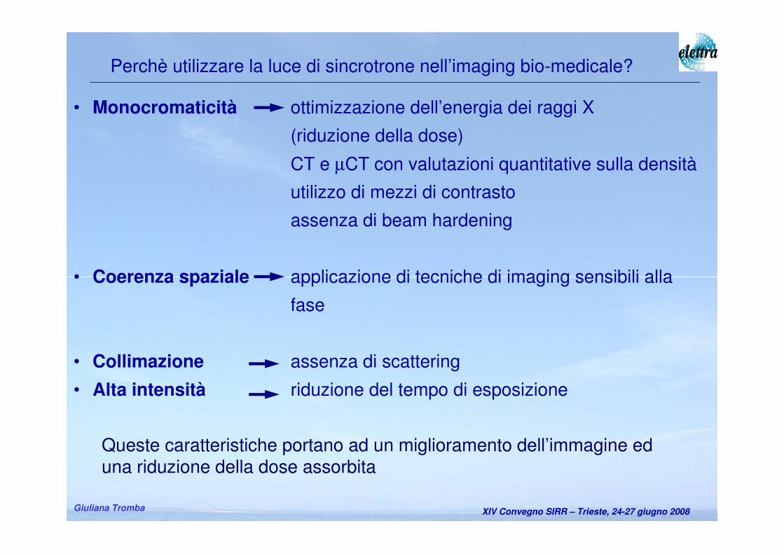
Perchè utilizzare la luce di sincrotrone nell’imaging bio-medicale?
• Monocromaticità ottimizzazione dell’energia dei raggi X
(riduzione della dose)
CT e µCT con valutazioni quantitative sulla densità
utilizzo di mezzi di contrasto
assenza di beam hardening
• Coerenza spaziale applicazione di tecniche di imaging sensibili alla
fase
• Collimazione assenza di scattering
• Alta intensità riduzione del tempo di esposizione
Queste caratteristiche portano ad un miglioramento dell’immagine eduna riduzione della dose assorbita
XIV Convegno SIRR – Trieste, 24-27 giugno 2008Giuliana Tromba 5
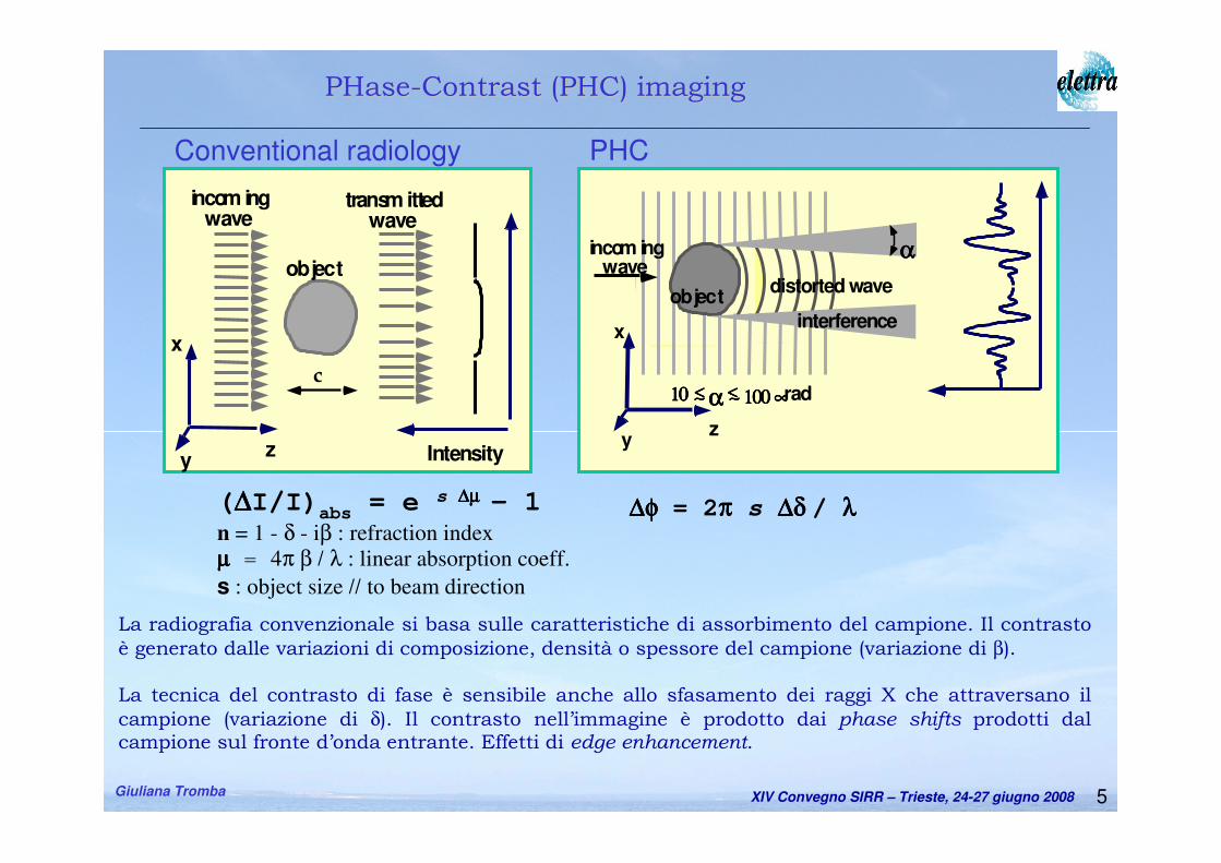
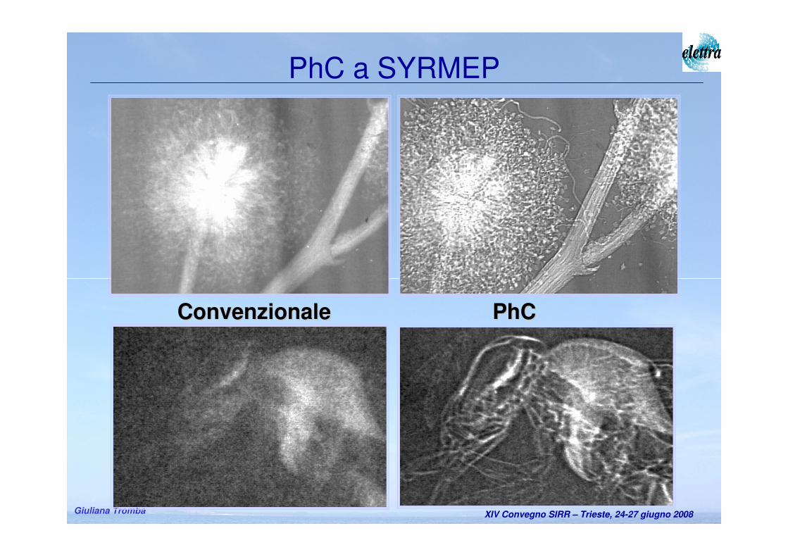
La radiografia convenzionale si basa sulle caratteristiche di assorbimento del campione. Il contrasto
è generato dalle variazioni di composizione, densità o spessore del campione (variazione di β).
La tecnica del contrasto di fase è sensibile anche allo sfasamento dei raggi X che attraversano il
campione (variazione di δ). Il contrasto nell’immagine è prodotto dai phase shifts prodotti dal campione sul fronte d’onda entrante. Effetti di edge enhancement.
Intensity
incom ingwave
x
yz
transm ittedwave
c
objectαααα
αααα11110000 ∼∼∼∼<<<< 111100000000 ∝∝∝∝rad∼∼∼∼<<<<
distorted wave
incom ingwave
x
yz
object
interference
Conventional radiology PHC
PHasePHase--Contrast (PHC)Contrast (PHC) imagingimaging
(∆∆∆∆I/I)abs
= e s ∆µ∆µ∆µ∆µ – 1
n = 1 - δ - iβ : refraction index
µµµµ = 4π β / λ : linear absorption coeff.
s : object size // to beam direction
∆φ∆φ∆φ∆φ = 2ππππ s ∆δ∆δ∆δ∆δ / λλλλ
XIV Convegno SIRR – Trieste, 24-27 giugno 2008Giuliana Tromba
PhCPhCConvenzionaleConvenzionale
PhC a SYRMEP
XIV Convegno SIRR – Trieste, 24-27 giugno 2008Giuliana Tromba
Progetto finanziato da Fondazione CRTrieste
Scopo: Esami di mammografia su un campione selezionato di pazienti
Target: Seni densi e/o disomogenei;
mammografia convenzionale con diagnosi incerta;
sospetto di falsi positivi.
Modalità: I Fase: radiografie planari con rivelatori commerciali;
II Fase: tomografia
Il progetto SYRMA (SYnchrotron Radiation for MAmmography)
Convenzione tra: Azienda Ospedaliera mista, Università di Trieste, Sincrotrone
Inizio sperimentazione: 13 marzo 2006
XIV Convegno SIRR – Trieste, 24-27 giugno 2008Giuliana Tromba8
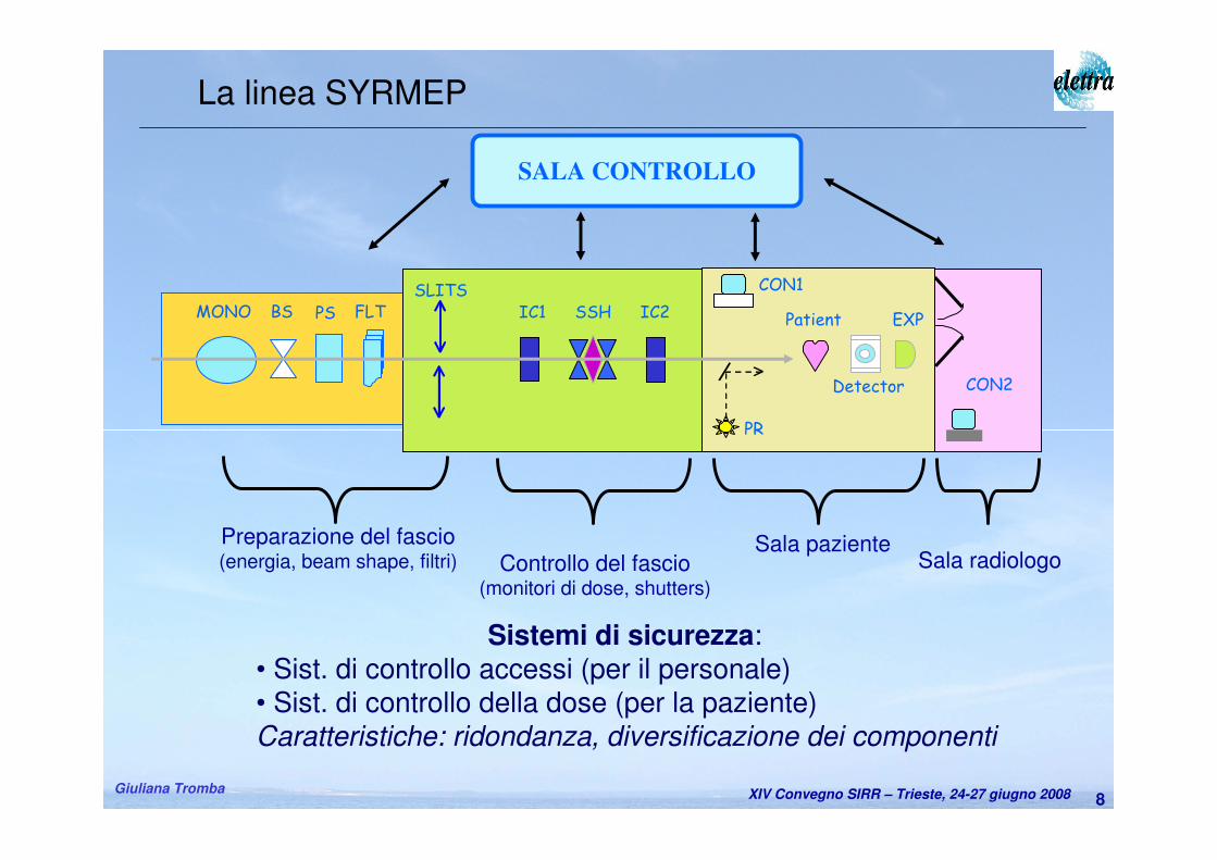
Preparazione del fascio(energia, beam shape, filtri) Controllo del fascio
(monitori di dose, shutters)
Sala pazienteSala radiologo
SALA CONTROLLO
FLTPSBSMONOSLITS
IC1 IC2SSH
CON1
PR
Patient
Detector
EXP
CON2
La linea SYRMEP
Sistemi di sicurezza:• Sist. di controllo accessi (per il personale)• Sist. di controllo della dose (per la paziente)Caratteristiche: ridondanza, diversificazione dei componenti
XIV Convegno SIRR – Trieste, 24-27 giugno 2008Giuliana Tromba9
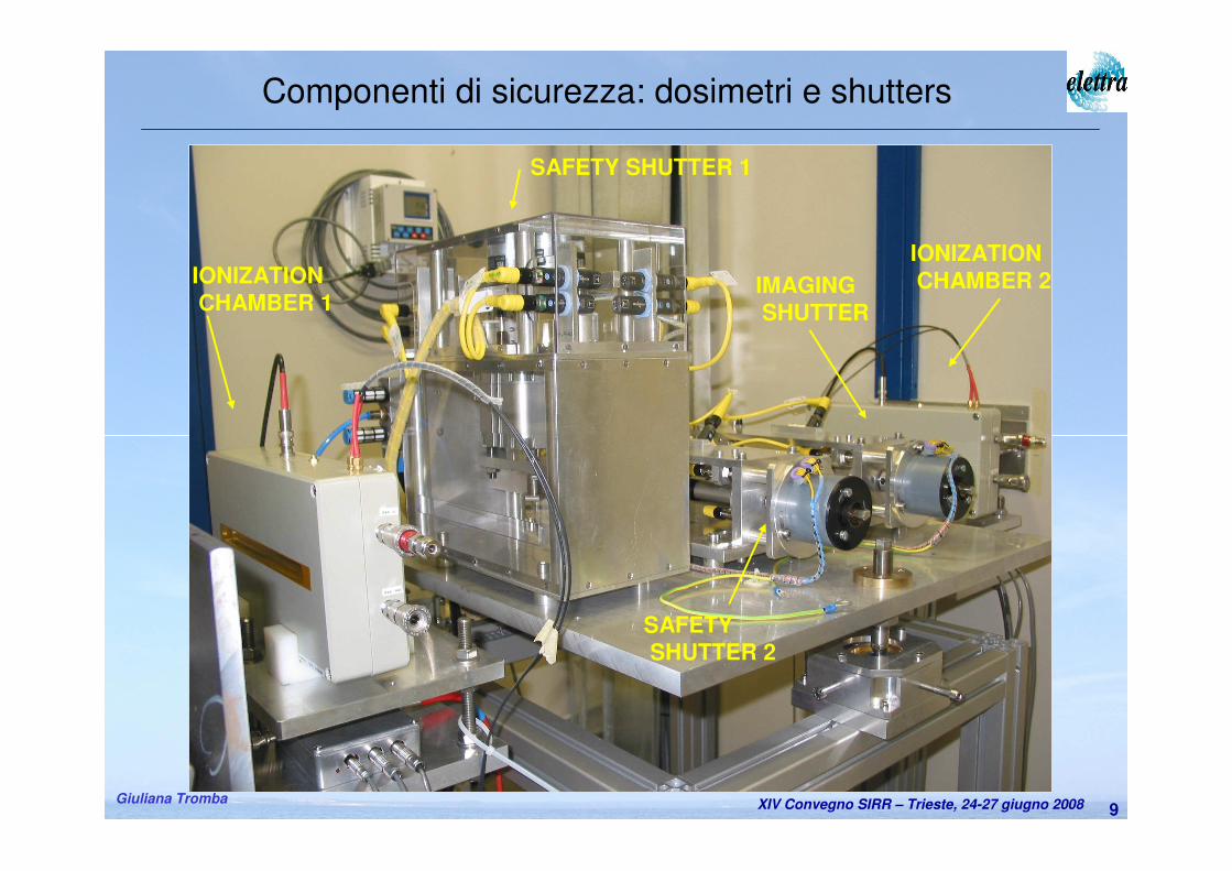
Componenti di sicurezza: dosimetri e shutters
IONIZATIONCHAMBER 2IONIZATION
CHAMBER 1
SAFETY SHUTTER 1
SAFETYSHUTTER 2
IMAGINGSHUTTER
XIV Convegno SIRR – Trieste, 24-27 giugno 2008Giuliana Tromba
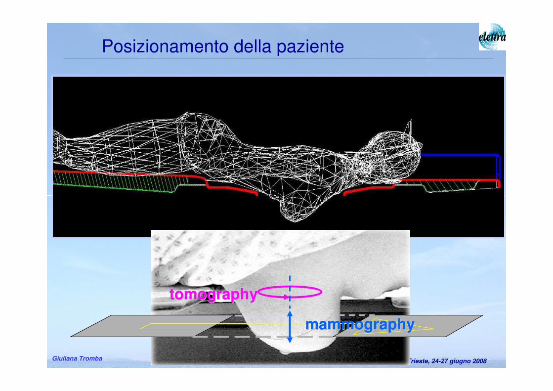
Posizionamento della paziente
tomographytomography
mammographymammography
XIV Convegno SIRR – Trieste, 24-27 giugno 2008Giuliana Tromba11
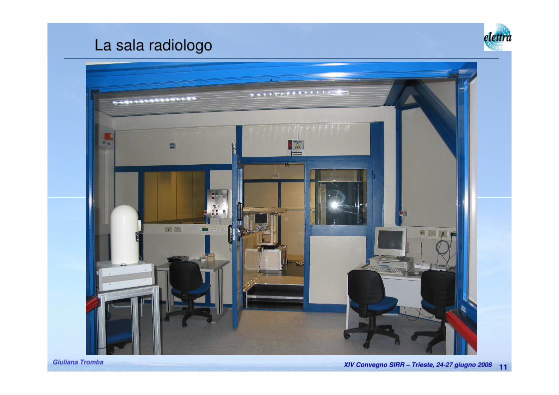
La sala radiologo
XIV Convegno SIRR – Trieste, 24-27 giugno 2008Giuliana Tromba12
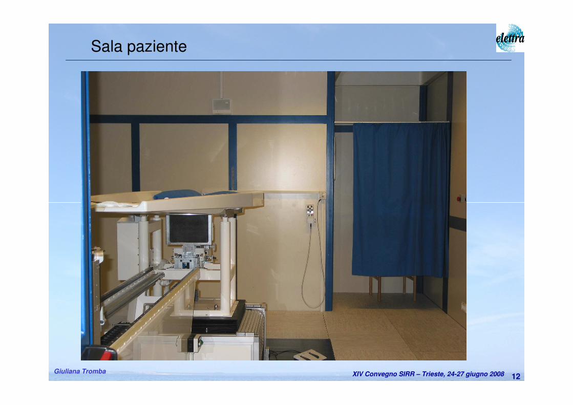
Sala paziente
XIV Convegno SIRR – Trieste, 24-27 giugno 2008Giuliana Tromba13
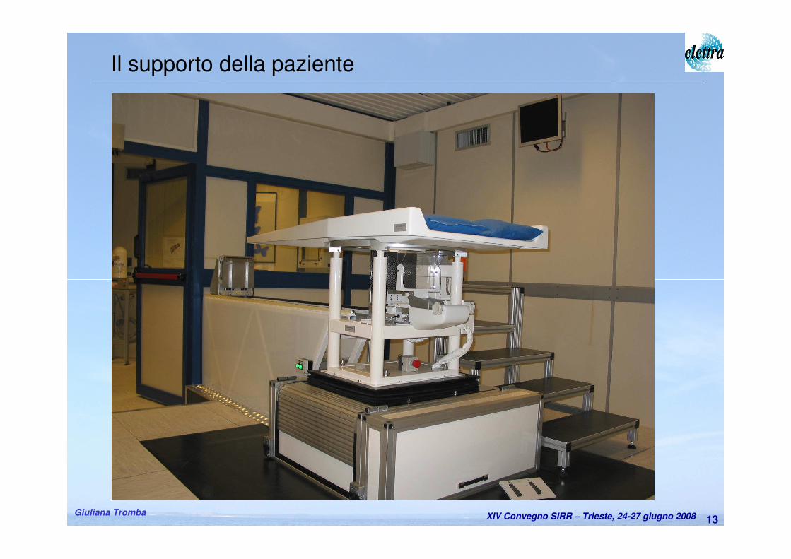
Il supporto della paziente
XIV Convegno SIRR – Trieste, 24-27 giugno 2008Giuliana Tromba14
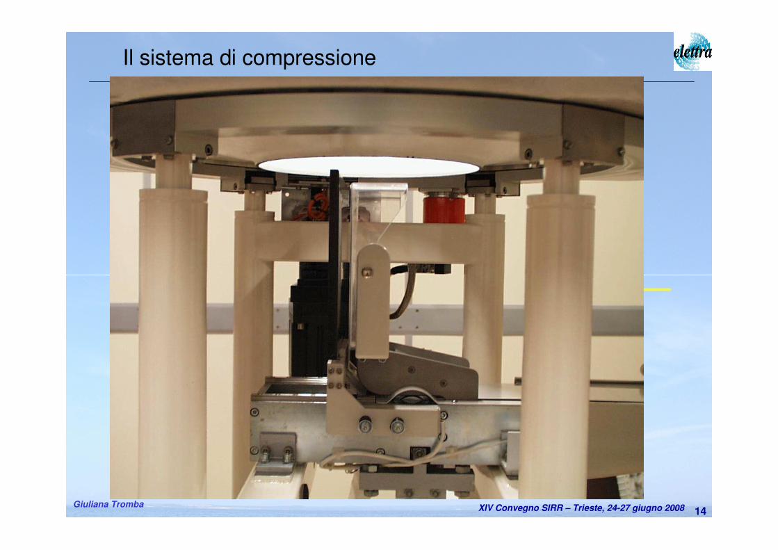
Il sistema di compressione
Patient support
Hole axis
Beam
Manual Motorized
ReferenceReleasing
CompressionDecompression
XIV Convegno SIRR – Trieste, 24-27 giugno 2008Giuliana Tromba15
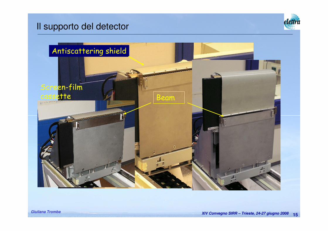
Il supporto del detector
Screen-filmcassette
Fixedshield
Entrance slit
Antiscattering shield
Beam
XIV Convegno SIRR – Trieste, 24-27 giugno 2008Giuliana Tromba16
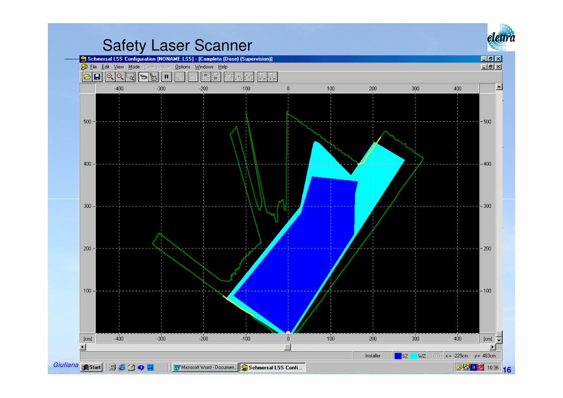
Safety Laser Scanner
• System by Schmersal based on laser IR diode (905 nm)
• Used to prevent collisions and protect personnel from X-ray unwanted exposure
• It recognizes two maps:• collision zone• X-ray hazard
• It can handle two possible interventions (pre-alarm and alarm)
XIV Convegno SIRR – Trieste, 24-27 giugno 2008Giuliana Tromba17
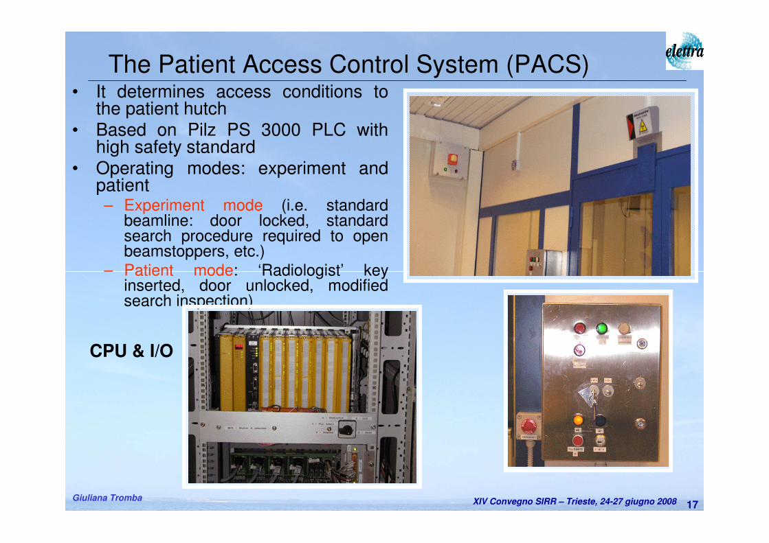
• It determines access conditions to the patient hutch
• Based on Pilz PS 3000 PLC with high safety standard
• Operating modes: experiment and patient– Experiment mode (i.e. standard
beamline: door locked, standard search procedure required to open beamstoppers, etc.)
– Patient mode: ‘Radiologist’ key inserted, door unlocked, modified search inspection)
The Patient Access Control System (PACS)
CPU & I/O
XIV Convegno SIRR – Trieste, 24-27 giugno 2008Giuliana Tromba18
• It operates in patient mode
• Aims:
– to prevent over-exposure to the patient
– to monitor the correct working conditions of all the components before and during a scan
• Alarm states:
– Malfunction of dose monitors
– Malfunction of support or film systems
– Mismatch of monochromator energy
– Overcome of skin doserate threshold
– Overcome of integrated dose threshold
• Actions:
– Abort of exam: closure of safety and imaging shutters
– Acoustic alarm
The Dose Control System (DCS)
XIV Convegno SIRR – Trieste, 24-27 giugno 2008Giuliana Tromba19
• Aims:
– to provide continuous dose monitoring during patient scan
– to optimize the X-ray beam (monochromator crystals
rocking) before each patient examinations
• Characteristics:
– Non destructive measurements
– Redundancy (IOC1, IOC2)
– High stability and reliability, wide dynamic range
– Quick response, unsensitivity to small vertical displacement of the X-ray beam
The dose and beam monitors
XIV Convegno SIRR – Trieste, 24-27 giugno 2008Giuliana Tromba20
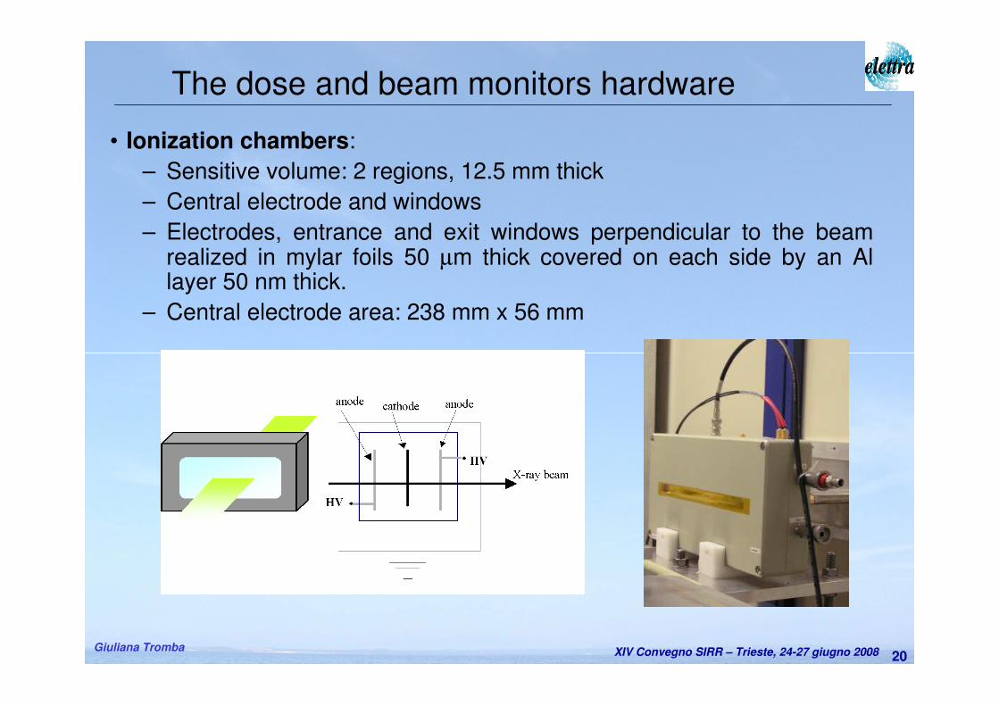
• Ionization chambers:
– Sensitive volume: 2 regions, 12.5 mm thick
– Central electrode and windows
– Electrodes, entrance and exit windows perpendicular to the beam realized in mylar foils 50 µm thick covered on each side by an Al layer 50 nm thick.
– Central electrode area: 238 mm x 56 mm
The dose and beam monitors hardware
XIV Convegno SIRR – Trieste, 24-27 giugno 2008Giuliana Tromba21
– The analog part of the readout electronics is placed within a sealed housing to minimize external electromagnetic pick up.
– The electronics integrates the charges released in the conversion gas over a predefined integration time.
– Readout is based on a commercial available integrated circuit (DDC112 from Burr Brown). 20 bit A/D convertion.
– A micro controller is used to generate the necessary initialization signals for the DDC 112 and to set the integration timing (from 0.5 ms to some s). 7 different gains can be set (ranging from 50 pC – 350 pCfull scale range)
– Integration time = 1 msec;
– The precision of the air kerma measurements is improved considering the average value of IOC readings in 1 sec, typically 1000.
– Gain = 50 pC (to assure a high sensitivity even for low currents measurements avoiding at the same time a possible saturation for the maximum available current at the beamline). 50 pC is the maximum interated charge measured current of 50 nA for an integration time of 1 msec).
The dose and beam monitors electronics
XIV Convegno SIRR – Trieste, 24-27 giugno 2008Giuliana Tromba22
– Response stability
• Measurements with respect to the Standard free air chamber in the National laboratory for ionizing radiation metrology (ENEA-INMRI lab) using calibrated sources
– Linearity of response
• Measured current is proportional to the beam horiz. dimension
– Saturation curve
– Ion ricombination (method by Boutillon*)
– Uniformity of response
• Over the sensitive volume the IC shows the same response
Preliminary dose monitors characterization
* M. Boutillon, “Volume recombination parameter in ionization chambers”, Phys.Med.Biol. 43, 2061-2072, 1998
XIV Convegno SIRR – Trieste, 24-27 giugno 2008Giuliana Tromba23
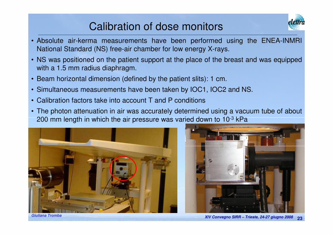
Calibration of dose monitors
• Absolute air-kerma measurements have been performed using the ENEA-INMRI
National Standard (NS) free-air chamber for low energy X-rays.
• NS was positioned on the patient support at the place of the breast and was equipped
with a 1.5 mm radius diaphragm.
• Beam horizontal dimension (defined by the patient slits): 1 cm.
• Simultaneous measurements have been taken by IOC1, IOC2 and NS.
• Calibration factors take into account T and P conditions
• The photon attenuation in air was accurately determined using a vacuum tube of about
200 mm length in which the air pressure was varied down to 10-3 kPa
XIV Convegno SIRR – Trieste, 24-27 giugno 2008Giuliana Tromba24
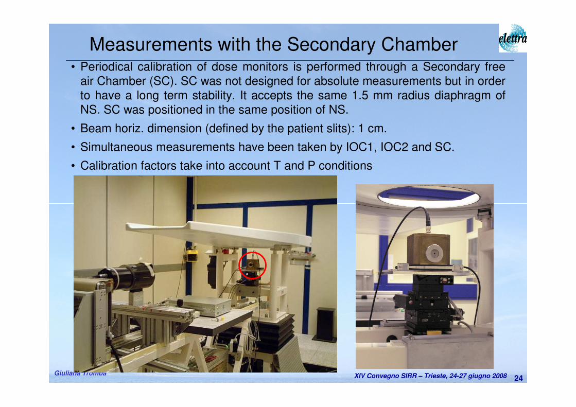
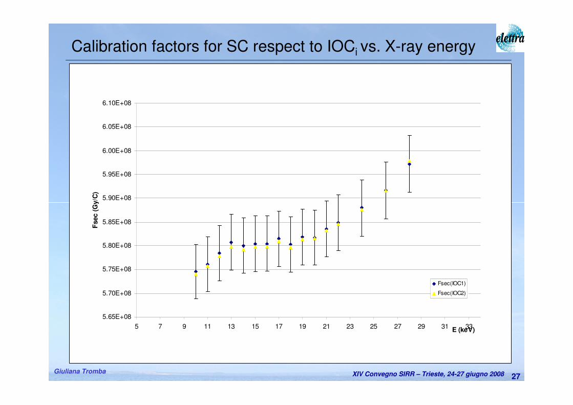
Measurements with the Secondary Chamber• Periodical calibration of dose monitors is performed through a Secondary free
air Chamber (SC). SC was not designed for absolute measurements but in order
to have a long term stability. It accepts the same 1.5 mm radius diaphragm of
NS. SC was positioned in the same position of NS.
• Beam horiz. dimension (defined by the patient slits): 1 cm.
• Simultaneous measurements have been taken by IOC1, IOC2 and SC.
• Calibration factors take into account T and P conditions
XIV Convegno SIRR – Trieste, 24-27 giugno 2008Giuliana Tromba25
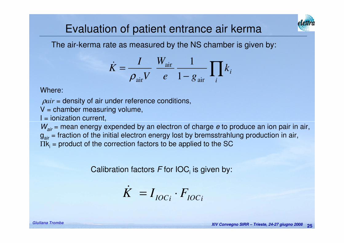
Evaluation of patient entrance air kerma
The air-kerma rate as measured by the NS chamber is given by:
∏−
=i
ikge
W
V
IK
air
air
air 1
1
ρ&
Where:
ρair = density of air under reference conditions,
V = chamber measuring volume,
I = ionization current,
Wair = mean energy expended by an electron of charge e to produce an ion pair in air,
gair = fraction of the initial electron energy lost by bremsstrahlung production in air,
Πki = product of the correction factors to be applied to the SC
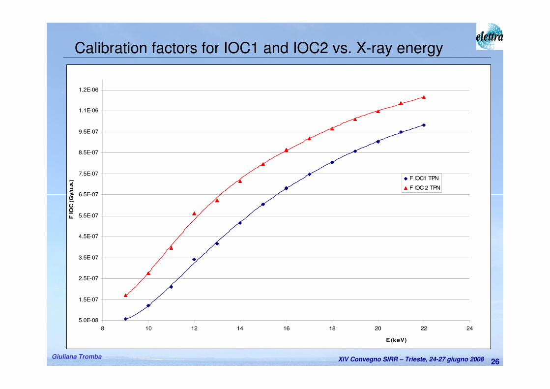
iIOCiIOC FIK ⋅=&
Calibration factors F for IOCi is given by:
XIV Convegno SIRR – Trieste, 24-27 giugno 2008Giuliana Tromba26
5.0E-08
1.5E-07
2.5E-07
3.5E-07
4.5E-07
5.5E-07
6.5E-07
7.5E-07
8.5E-07
9.5E-07
1.1E-06
1.2E-06
8 10 12 14 16 18 20 22 24
E (keV)
F IO
C (
Gy/u
.a.)
F IOC1 TPN
F IOC 2 TPN
Calibration factors for IOC1 and IOC2 vs. X-ray energy
XIV Convegno SIRR – Trieste, 24-27 giugno 2008Giuliana Tromba27
Calibration factors for SC respect to IOCi vs. X-ray energy
5.65E+08
5.70E+08
5.75E+08
5.80E+08
5.85E+08
5.90E+08
5.95E+08
6.00E+08
6.05E+08
6.10E+08
5 7 9 11 13 15 17 19 21 23 25 27 29 31 33E (keV)
Fsec (
Gy/C
)
Fsec(IOC1)
Fsec(IOC2)
XIV Convegno SIRR – Trieste, 24-27 giugno 2008Giuliana Tromba28
The Supervision and Human-Machine Interface (SHMI) system
• Functions:
– Insert initialisation/calibration data
– Register patient data
– Select the X-ray energy and optimize the beam through the
Beamline Control System
– Control the congruency of all the examination parameters
– Manage the pre-scan
– Carry out the scan
– Register dose report
XIV Convegno SIRR – Trieste, 24-27 giugno 2008Giuliana Tromba29
Exam initialization• Input of patient parameters,• Choice of X-ray energy (according to the breast thickness and on
an estimate of breast glandularity class (i.e. low, medium, high)),• Beam optimization.
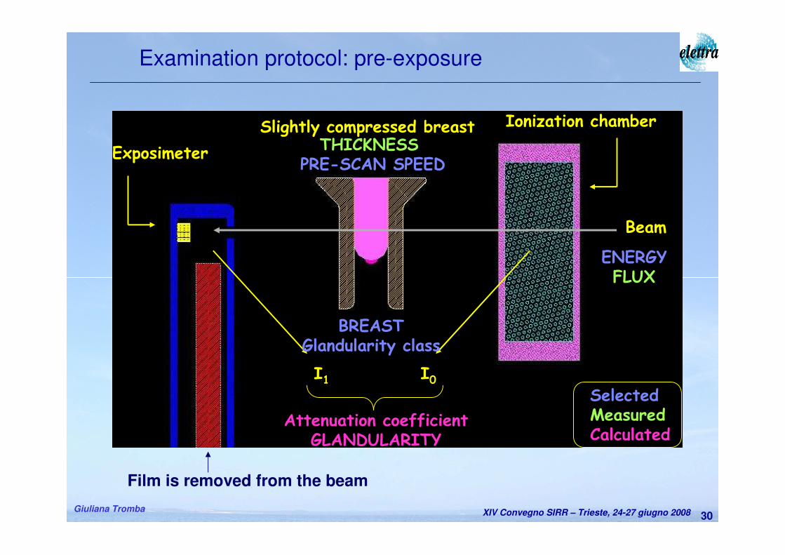
Prescan• It is a scan over a small breast portion in a range selected by
radiologist.
• It aims to measure the breast absorption properties and to evaluatethe real breast glandularity.
• The results of prescan are used to confirm the choice of the X-ray energy and to calculate the scan speed.
• The delivered dose is 5-10 % the examination dose.
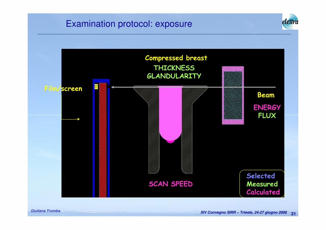
Exam
• The exam is a simultaneous scan of breast and detector in a range selected by radiologist.
Examination Protocol
XIV Convegno SIRR – Trieste, 24-27 giugno 2008Giuliana Tromba30
Examination protocol: pre-exposure
I0I1
Attenuation coefficientGLANDULARITY
Ionization chamber
Exposimeter
Slightly compressed breast
Beam
SelectedMeasuredCalculated
BREASTGlandularity class
THICKNESSPRE-SCAN SPEED
ENERGYFLUX
Film is removed from the beam
XIV Convegno SIRR – Trieste, 24-27 giugno 2008Giuliana Tromba31
THICKNESSGLANDULARITY
ENERGYFLUX
SCAN SPEEDSelectedMeasuredCalculated
BeamFilm/screen
Compressed breast
Examination protocol: exposure
XIV Convegno SIRR – Trieste, 24-27 giugno 2008Giuliana Tromba32
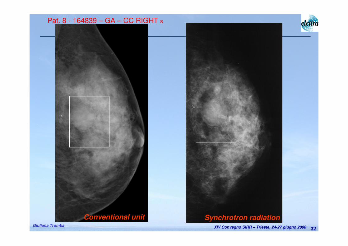
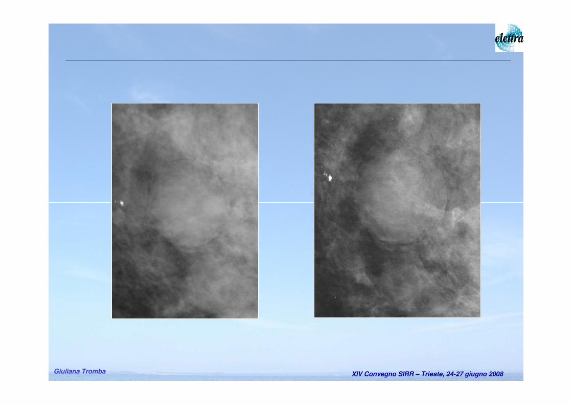
Pat. 8 - 164839 – GA – CC RIGHT s
Synchrotron radiationConventional unit
XIV Convegno SIRR – Trieste, 24-27 giugno 2008Giuliana Tromba
XIV Convegno SIRR – Trieste, 24-27 giugno 2008Giuliana Tromba34
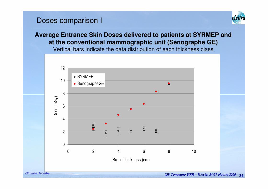
Average Entrance Skin Doses delivered to patients at SYRMEP and at the conventional mammographic unit (Senographe GE)
Vertical bars indicate the data distribution of each thickness class
0
2
4
6
8
10
12
0 2 4 6 8 10
Breast thickness (cm)
Dose (m
Gy)
SYRMEP
SenographeGE
Doses comparison I
XIV Convegno SIRR – Trieste, 24-27 giugno 2008Giuliana Tromba35
0
1
1
2
2
3
0 1 2 3 4 5 6 7 8 9
Breast thickness (cm)
Dose (m
Gy)
SYRMEP
SenographeGE
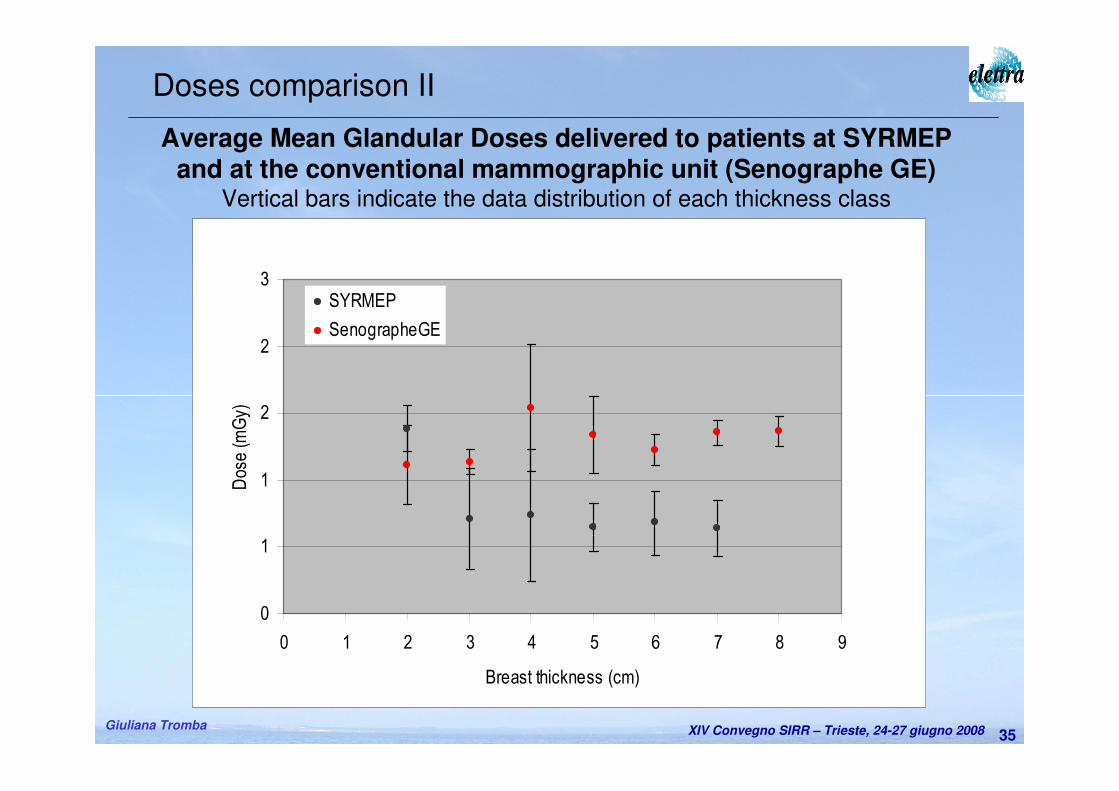
Average Mean Glandular Doses delivered to patients at SYRMEP and at the conventional mammographic unit (Senographe GE)
Vertical bars indicate the data distribution of each thickness class
Doses comparison II
XIV Convegno SIRR – Trieste, 24-27 giugno 2008Giuliana Tromba36
First protocol of clinical mammography with SR is started.
– Promising results obtained on the first 46 patients:
• Safety and Supervision systems show high reliability and efficiency.
• ESDs and MGDs are lower than the ones of conventional clinical unit,
improved image quality (contrast & spatial resolution).
– Patients are easily recruited, no negative reactions.
– Need to implement soon:
• a digital detector (to improve image, increase the X-ray energy, reduce
dose, phase retrieval…etc).
– Challenging upgrades:
• use of tomosyntesis/tomography to recognize the lesions overlap.
Conclusions and perspectives
XIV Convegno SIRR – Trieste, 24-27 giugno 2008Giuliana Tromba37
A.Abrami, K.Casarin, V.Chenda, D.Dreossi, R.H. Menk, E.Quai, A.VascottoSincrotrone Trieste
F. Arfelli, E. Castelli, R. Longo, L. Rigon, T. Rokvic(*), E. VallazzaDipartimento di Fisica, Università di Trieste e INFN, Sezione di Trieste
(*)Anche al Dipartimento di Fisica, Università di Belgrado
M.A. Cova, E. Quaia, D. Sanabor, M. Tonutti, F. ZanconatiDip. Univ. Clinico di Scienze Cliniche, Morf. e Tecnologiche, Università di Trieste
P. BregantStrutt. Complessa di Fisica Sanitaria, Az. Osp.- Universitaria ‘Ospedali Riuniti di Trieste’
M. Bovi, F. Laitano, M.P. ToniIstituto Nazionale di Metrologia delle Radiazioni Ionizzanti, ENEA - CR Casaccia
Acknowledgements
Grazie per l’attenzione


![Sirr al-Asrar [Arabic/Urdu]](https://img.pdfslide.net/doc/110x75/577cb0eb1a28aba7118b5cb9/sirr-al-asrar-arabicurdu.jpg)