Embed Size (px)
Citation preview
ILE, Osaka
Fast ignition Laser Fusion Reactor KOYO-F- Summary from design committee of FI
laser fusion reactor -
T. Norimatsu
Institute of Laser Engineering, Osaka University
IFE Forum
Presented at US-Japan workshop on
Power Plant Studies and related Advanced Technologies with EU participation
ILE, Osaka
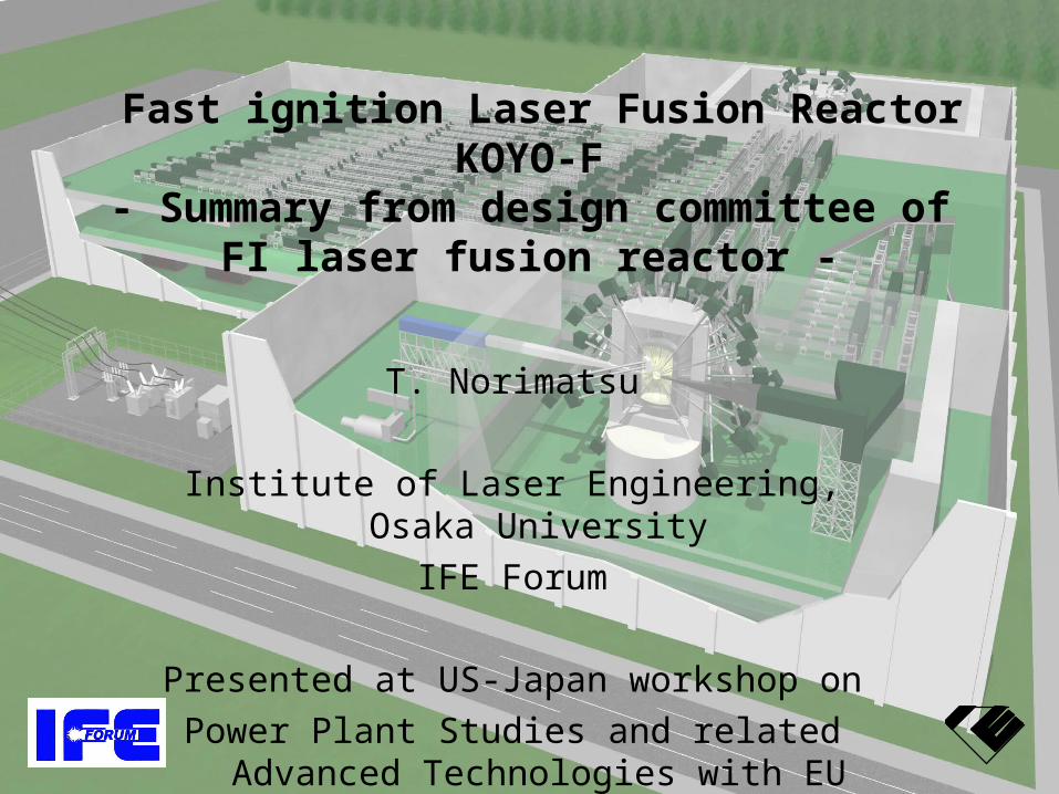
After the Roadmap committee, we organized a conceptual design committee to make the issue clear.
In total, 34 working group meetings were held from March 2004 to Sep. 2005.
• Chair; A. Tomabechi• Co-chair; Y. Kozaki (IFE, Forum) T. Norimatsu (ILE, Osaka)
Core plasma Working Group
H. Azechi (ILE, Osaka)
K. Mima (ILE, Osaka)
Y. Nakao (Kyushu U.)
H. Sakagami (Hyogo U.)
H. Shiraga (ILE, Osaka)
R. Kodama (ILE, Osaka)
H. Nagatomo (ILE, Osaka)
T. Jhozaki (ILE, Osaka)
Laser Working Group
N. Miyanaga (ILE, Osaka)
K. Ueda (U. Elec.Com.)
Y. Owadano (Nat. I. Adv. Ind. Sci.)
M. Nakatsuka (ILE, Osaka.)
K. Yoshida (Osaka)
H. Nakano (Kinki U.)
H. Kubomura (Hamamatsu Co.)
K. Kawashima (Hamamatsu Co)
Y. Suzuki (Laser Front Tech.)
T. Jitsuno (ILE, Osaka)
H. Fujita (ILE, Osaka)
J. Kawanaka (ILE, Osaka)
T. Kanabe (Fukui U.)
Y. Fujimoto ( ILE, Osaka)
K. Tsubakimoto (ILE, Osaka)
Y. Furukawa (ILE, Osaka)
Target Working Group
T. Norimatsu (ILE, Osaka)
A. Iwamoto (NIFS)
T. Endo (Hiroshima U.)
H. Yoshida (Gifu U.)
M. Nishikawa (Kyushu U.)
S. Konishi (Kyoto U.)
Plant system Working Group
Y. Kozaki (IFE, Forum)
Y. Ueda (Osaka U.)
K. Okano (Cent. Res. Ins.)
T. Kunugi (Kyoto U.)
Y. Sakawa (Nagoya U.)
H. Nakano (Kinki U.)
A. Sagara (NIFS)
Y. Soman (Mitsubishi Co)
M. Nishikawa (Kyushu U.)
Hayashi (JAERI)
H. Furukawa (ILE, Osaka)
M. Nakai (ILE, Osaka)
T. Kanabe (Fukui U.)
Y. Fujimoto ( ILE, Osaka)
K. Tsubakimoto (ILE, Osaka)
Y. Furukawa (ILE, Osaka)
The committee is supported by IFE Forum and ILE, Osaka Univ.
ILE, Osaka
Outline
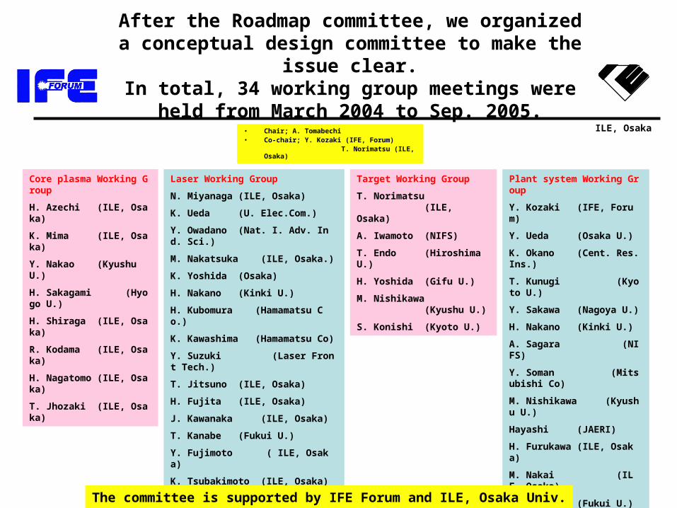
• Introduction– Fast ignition– Gain estimation and the emission
• Chamber and plant system• Laser system• Fueling system
ILE, Osaka
1
10
100
10(MJ)
0.1 1
US-NIF
KOYO(Osaka design)
Fu
sio
n G
ain
Central Ignition
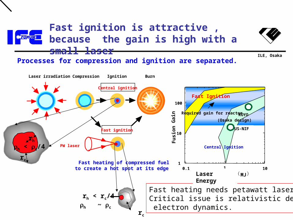
Processes for compression and ignition are separated.
Central ignition
Fast ignition
Laser irradiation Compression Ignition Burn
PW laser
Fast heating of compressed fuelto create a hot spot at its edge
Fast Ignition
Required gain for reactor
rh
h < c/4
rc
rc
rh < rc/4h ~ c
Fast heating needs petawatt laser.Critical issue is relativistic dense electron dynamics.
Laser Energy
Fast ignition is attractive , because the gain is high with a small laser
ILE, Osaka
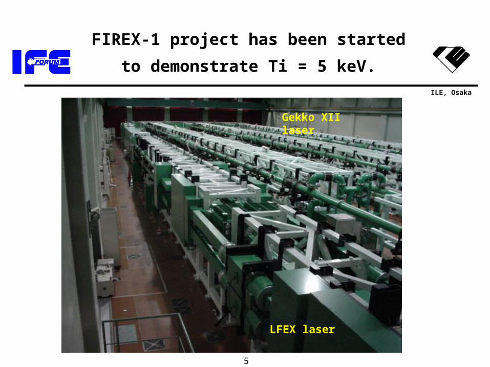
FIREX-1 project has been started to
demonstrate Ti = 5 keV.
5
LFEX laser
Gekko XII laser
ILE, Osaka
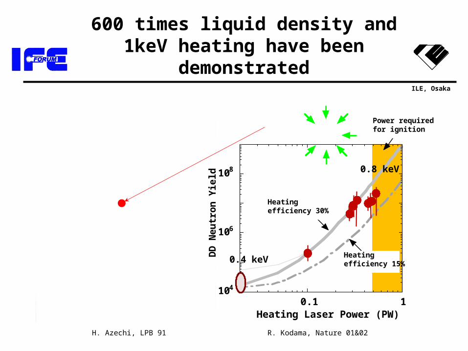
600 times liquid density and 1keV heating have been demonstrated
104
106
108
0.1 1
Neu
tro
n Y
ield
Heating Laser Power (PW)
加熱効率15%
30%加熱効率
点火に必要と予測されるパワー
R. Kodama, Nature 01&02H. Azechi, LPB 91
Heatingefficiency 30%
Heatingefficiency 15%0.4 keV
0.8 keV
DD
Neu
tro
n Y
ield
Power requiredfor ignition
ILE, Osaka
2 実験によりベンチマークされた 次元シミュレーションにより,コーンターゲットに2000おいても固体密度の 倍以上の圧縮が予測されている.
GA阪大ー 共同研究
FIREXしたがって を実施するキーディシジョンを下すことができる段階に入ったと思われる.
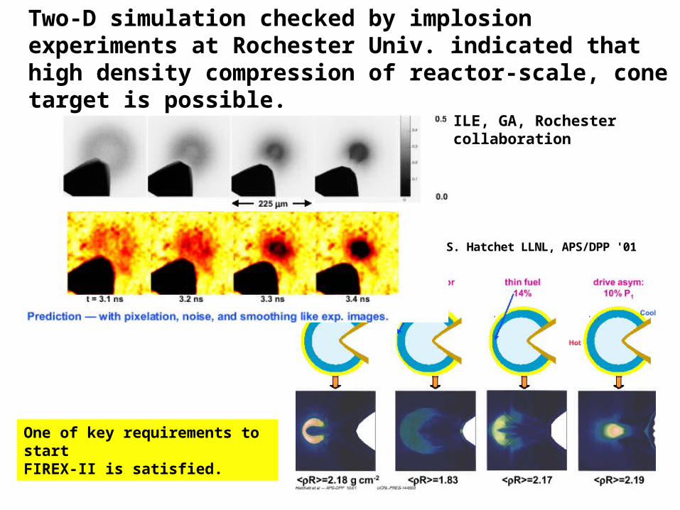
S. Hatchet LLNL, APS/DPP '01
Two-D simulation checked by implosion experiments at Rochester Univ. indicated that high density compression of reactor-scale, cone target is possible.
ILE, GA, Rochestercollaboration
One of key requirements to start FIREX-II is satisfied.
ILE, Osaka
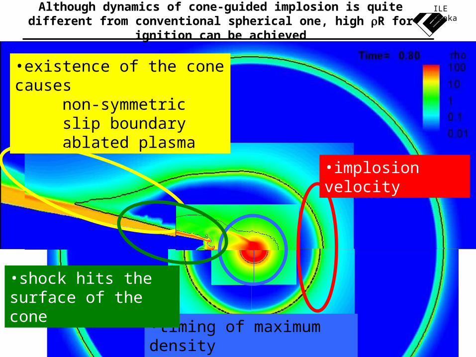
ILE OsakaAlthough dynamics of cone-guided implosion is quite different from conventional spherical one, high R for ignition can be achieved
•existence of the cone causesnon-symmetric slip boundaryablated plasma
•implosion velocity
•timing of maximum density•hot spot
•shock hits the surface of the cone
ILE, Osaka
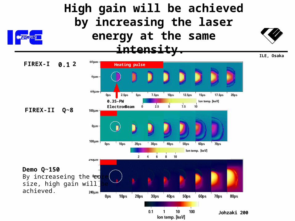
High gain will be achieved by increasing the laser energy at the
same intensity.
FIREX-II Q~8
Demo Q~150 By increaseing the core size, high gain will be achieved.
0.35-PW Electron Beam
FIREX-I Q~0.2 Heating pulse
Johzaki 2003
0.1
ILE, Osaka
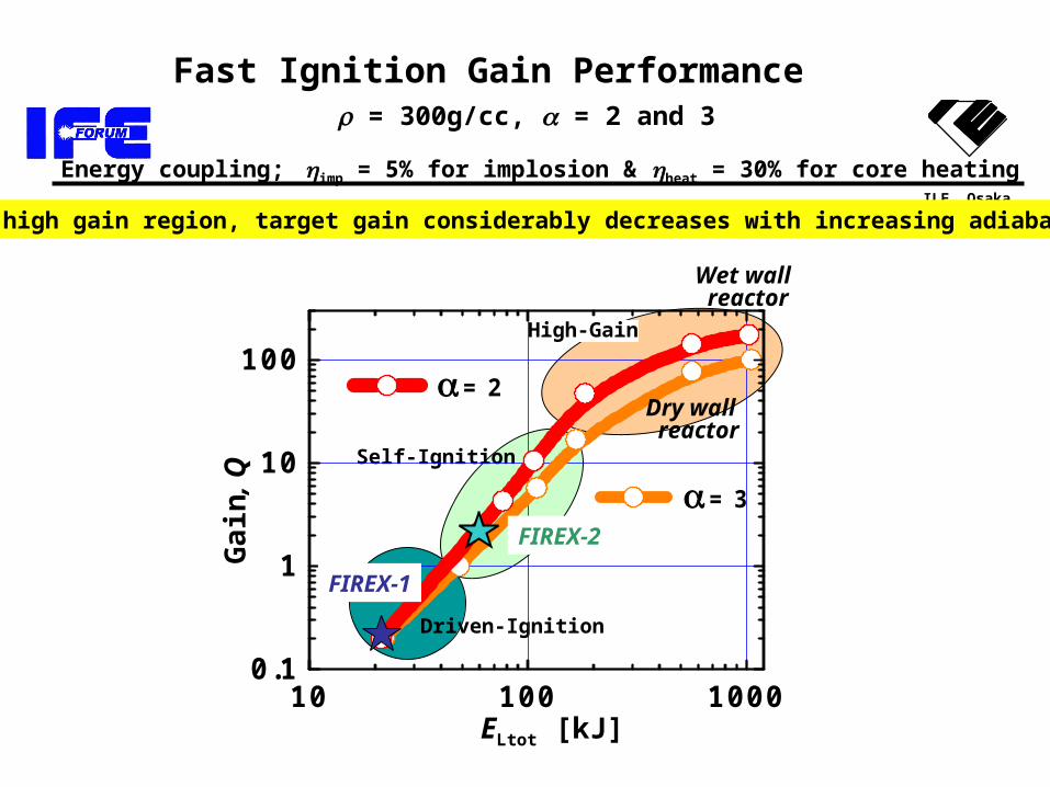
Fast Ignition Gain Performance = 300g/cc, = 2 and 3
Energy coupling; imp = 5% for implosion & heat = 30% for core heating
In high gain region, target gain considerably decreases with increasing adiabat .
Self-Ignition
High-Gain
Driven-Ignition
ELtot [kJ]
Ga
in, Q = 3
10 100 10000.1
1
10
100 = 2
FIREX-1
FIREX-2
Wet wall reactor
Dry wall reactor
ILE, Osaka
Outline
• Introduction• Chamber and plant system
– Chamber structure– Pumping– Protection of final optics
• Laser system• Fueling system
ILE, Osaka
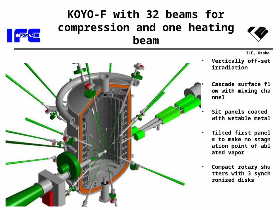
KOYO-F with 32 beams for compression and one heating beam
• Vertically off-set irradiation
• Cascade surface flow with mixing channel
• SiC panels coated with wetable metal
• Tilted first panels to make no stagnation point of ablated vapor
• Compact rotary shutters with 3 synchronized disks
ILE, Osaka
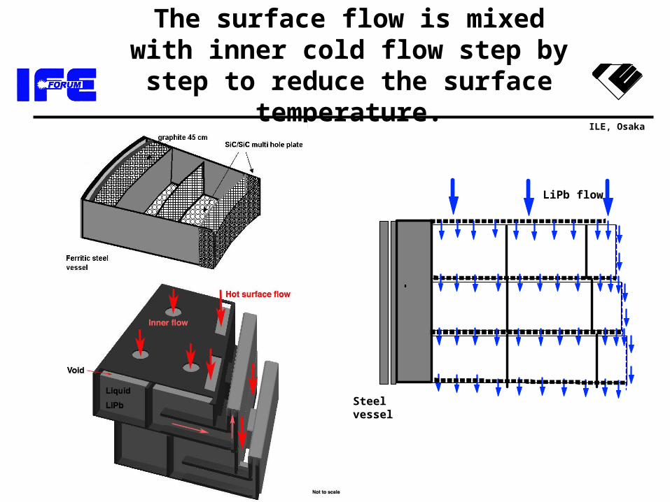
The surface flow is mixed with inner cold flow step by step to reduce the
surface temperature.
Steel vessel
LiPb flow
ILE, Osaka
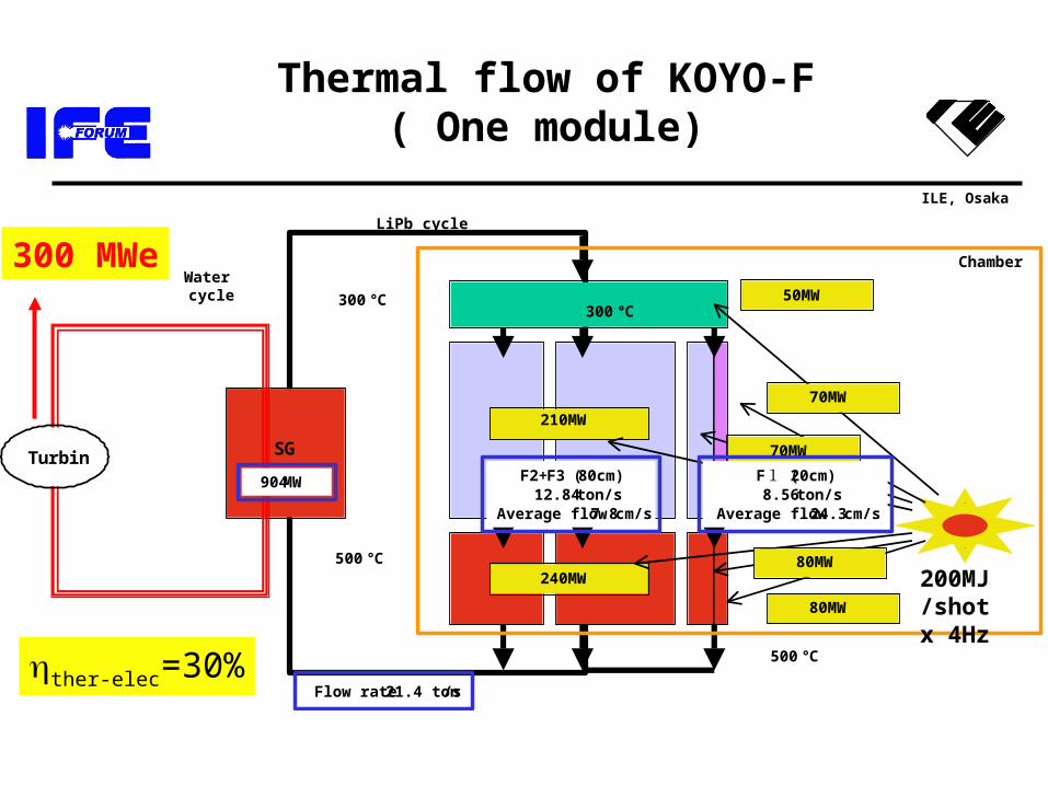
Thermal flow of KOYO-F( One module)
SGTurbin
500℃
300℃300℃
50MW
210MW
70MW
70MW
240MW
80MW
80MW
500℃
F2+F3 (80cm)12.84 ton/s
Average flow 7.8 cm/s
F1 (20cm)8.56 ton/s
Average flow 24.3 cm/s
Flow rate 21.4 ton /s
904MW
Watercycle
Chamber
LiPb cycle
200MJ/shot x 4Hz
300 MWe
ther-elec=30%
ILE, Osaka
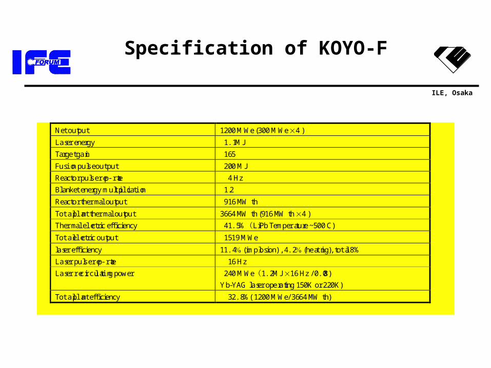
Specification of KOYO-F
Net output 1200 MWe (300 MWe 4 )
Laser energy 1.1 MJ
Target gain 165
Fusion pulse out put 200 MJ
Reactor pulse rep-rate 4 Hz
Blanket energy multiplication 1.2
Reactor thermal output 916 MWth
Total plant thermal output 3664 MWth (916 MWth 4 )
Thermal electric efficiency 41.5 %(LiPb Temperature ~500 C)
Total electric output 1519 MWe
laser efficiency 11.4 (implosion) , 4.2 (heating), total 8%
Laser pulse rep-rate 16 Hz
Laser recirculating power 240 MWe(1.2 MJ 16 Hz / 0.08)
Yb-YAG laser operating 150K or 220K)
Total plant efficiency 32.8 %( 1200 MWe/ 3664 MWth)
ILE, Osaka
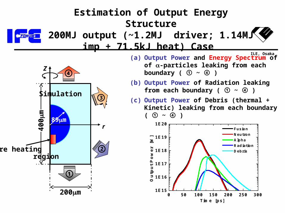
Estimation of Output Energy Structure200MJ output (~1.2MJ driver; 1.14MJ imp +
71.5kJ heat) Case
(a) Output Power and Energy Spectrum of of -particles leaking from each boundary ( ① ~ ④ )
(b) Output Power of Radiation leaking from each boundary ( ① ~ ④ )
(c) Output Power of Debris (thermal + Kinetic) leaking from each boundary ( ① ~ ④ )
Z
r
Simulation box
Core heating region
②
①
③
④
200m
400
m
89m
0 50 100 150 200 250 3001E15
1E16
1E17
1E18
1E19
1E20
Ou
tpu
t P
ow
er
[W
]
Time [ps]
Fusion Neutron Alpha Radiation Debris
ILE, Osaka
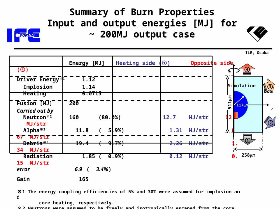
Energy [MJ] Heating side ( )① Opposite side ( )④
Driver Energy 1※ 1.12 Implosion 1.14 Heating 0.0715
Fusion [MJ] 200Carried out by Neutron 2※ 160 (80.0%) 12.7 MJ/str 12.7 MJ/str Alpha 3※ 11.8 ( 5.9%) 1.31 MJ/str 0.67 MJ/str Debris 4※ 19.4 ( 9.7%) 2.26 MJ/str 1.34 MJ/str Radiation 1.85 ( 0.9%) 0.12 MJ/str 0.15 MJ/str error 6.9 ( 3.4%)
Gain 165
※1 The energy coupling efficiencies of 5% and 30% were assumed for implosion and core heating, respectively. ※2 Neutrons were assumed to be freely and isotropically escaped from the core. ※3 Alpha particle: Leakage/Source = 29.8% (70.2% is deposited inside the core.)※4 Constitution (energy D:35.5%, T:49.9%, :14.3% / Number D:43.6%, T:44.5%, :11.5%)
Summary of Burn PropertiesInput and output energies [MJ] for ~ 200MJ output
case
Z
r
Simulation box
②
①
③
④
258m
511
m
117m
ILE, Osaka
P 8
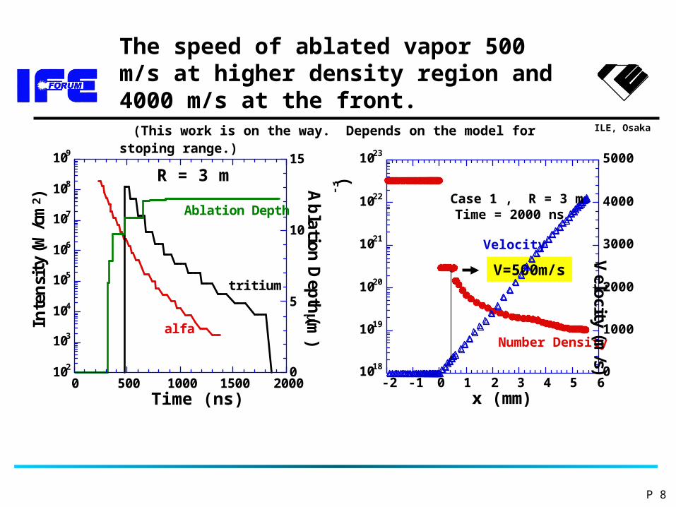
The speed of ablated vapor 500 m/s at higher density region and 4000 m/s at the front. (This work is on the way. Depends on the model for stoping range.)
102
103
104
105
106
107
108
109
0
5
10
15
0 500 1000 1500 2000
R = 3 m
alfa
tritium
Ablation Depth
Inte
nsi
ty (
W/c
m2 )
A
bla
tion
Dep
th (m
)
Time (ns)
V=500m/s
1018
1019
1020
1021
1022
1023
0
1000
2000
3000
4000
5000
-2 -1 0 1 2 3 4 5 6
Case 1 , R = 3 m Time = 2000 ns
Number Density
Velocity
Nu
mb
er D
ensi
ty (c
m
-3 )
Velocity
(m/s)
x (mm)
ILE, Osaka
r(m)
z(m)
4
3
6
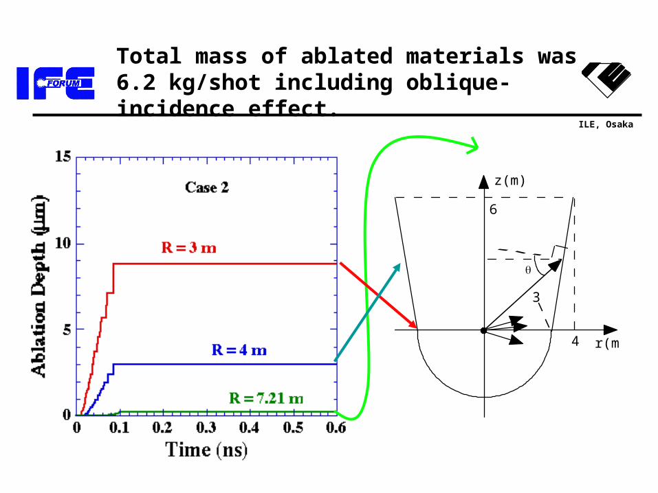
Total mass of ablated materials was 6.2 kg/shot including oblique-incidence effect.
ILE, Osaka
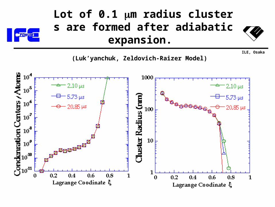
Lot of 0.1 m radius clusters are formed after adiabatic expansion.
(Luk’yanchuk, Zeldovich-Raizer Model)
ILE, Osaka
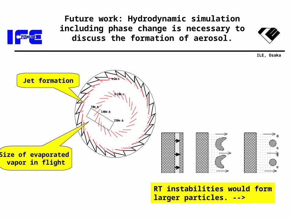
Future work: Hydrodynamic simulation including phase change is necessary to discuss the
formation of aerosol.
t=10ms
t=2ms
250m/s
140m/s
70m/s
Jet formation
Size of evaporated vapor in flight
RT instabilities would formlarger particles. -->
ILE, Osaka
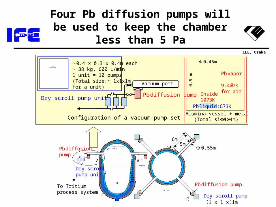
Four Pb diffusion pumps will be used to keep the chamber less than 5 Pa
Vacuum port
0.45m
0.9
m
Inside:1073K
Pb liquid:673K
Pb vapor
9.4m3/sfor air
Alumina vessel + metal jacket(Total size:~ 1x1m)
Pb diffusion pumpDry scroll pump unit
To Tritiumprocess system
~ 0.4 x 0.3 x 0.4m each~ 38 kg, 600 L/min1 unit = 10 pumps(Total size:~ 1x1x1mfor a unit)
Qui ckTi meý DzTI FFÅi LZWÅj êLí £ÉvÉçÉOÉâÉÄ
ǙDZÇÃÉsÉNÉ̀ ÉÉǾå©ÇÈÇ…ÇÕï KóvÇ ÇÅB
Configuration of a vacuum pump set
A'A
10000.00
LiPb 上部ブランケット300 ℃
A-A' 断面図
LiPb 1/100 mm液体壁チェンバ-概念図 単位
φ6000.00
Fusion output 200 MJ / pulse, 800 MW,Pulse rep-ra tes 4 Hz Chamber inner radius 3.0 m, upper wall distance from burning center 10.0 m Pulse heat load max. 32 J / cm2, upper wall 2.9 J / cm2 average heat load max. 128 W / cm 2, upper wall 11.5 W / cm2 Neutron wall load max. 5.6 MW / m 2, upper wall 0.5 MW / m2
A A’
6m
0.55m
Dry scroll pump unit(1 x 1 x 1m)
5m
Pb diffusion pump
Pb diffusionpump
Dry scrollpump unit
ILE, Osaka
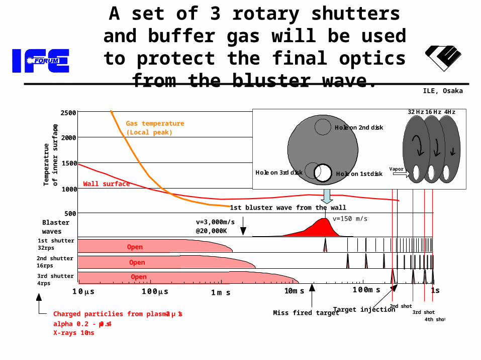
A set of 3 rotary shutters and buffer gas will be used to protect the final
optics from the bluster wave.
1 m s
2nd shot3rd shot
4th shot
1s1 0 s 1 0 0s 10ms 1 0 0ms
2nd shutter 16rps
3rd shutter 4rps
1st shutter 32rps
Target injectionMiss fired target
1st bluster wave from the wall
v=3,000m/s @20,000K
v=150 m/s
Charged particlies from plasma 1 - 2 μ s
alpha 0.2 - 0.4 μ s X-rays 10 ns
Blaster waves
1000
1500
2000
Tem
pe
ratr
ue
o
f in
ne
r s
urf
ac
e (
K)
Open
Open
Open
2500
500
Gas temperature (Local peak)
Wall surface
Hole on 1st disk
Hole on 2nd disk
Hole on 3rd disk
32 Hz 16 Hz 4Hz
Vapor
ILE, Osaka
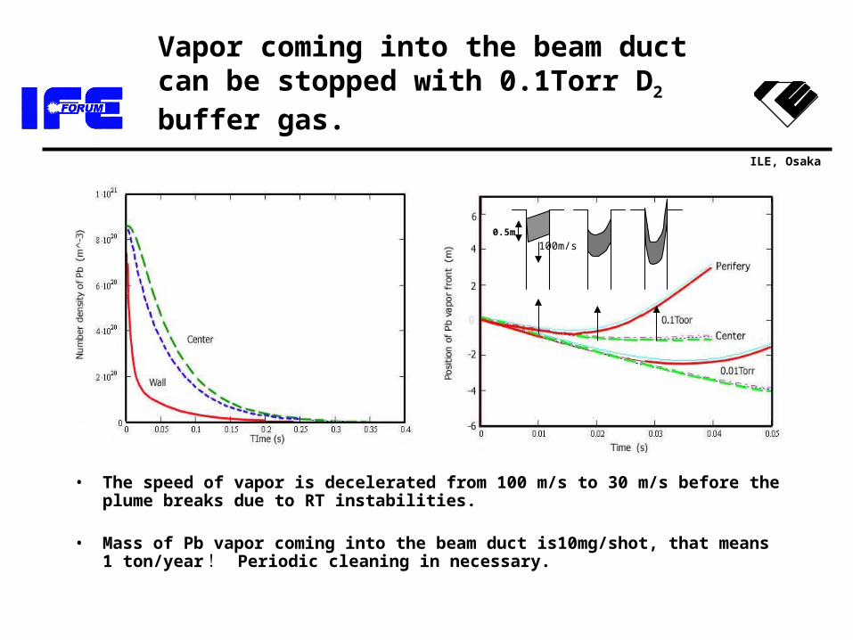
Vapor coming into the beam duct can be stopped with 0.1Torr D2 buffer gas.
• The speed of vapor is decelerated from 100 m/s to 30 m/s before the plume breaks due to RT instabilities.
• Mass of Pb vapor coming into the beam duct is10mg/shot, that means 1 ton/year ! Periodic cleaning in necessary.
0.5m
100m/s
ILE, Osaka
Outline
• Introduction– Fast ignition– Core plasma
• Chamber and plant• Laser system
– Cooled, ceramic Yb:YAG– Beam distributor
• Fueling system
ILE, Osaka
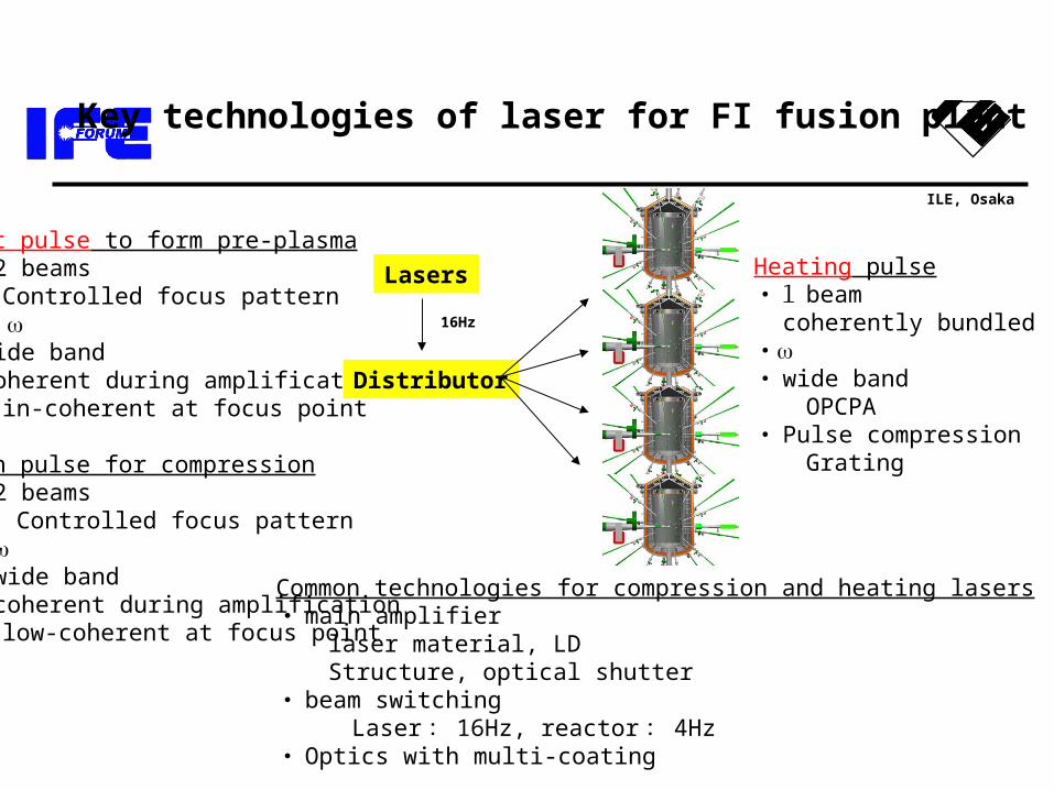
Foot pulse to form pre-plasma・ 32 beams Controlled focus pattern・ 2 ・ wide band・ coherent during amplification in-coherent at focus point
Main pulse for compression・ 32 beams Controlled focus pattern ・ 3・ wide band・ coherent during amplification low-coherent at focus point
Heating pulse・1 beam coherently bundled・・ wide band OPCPA・ Pulse compression Grating
Common technologies for compression and heating lasers・main amplifier laser material, LD Structure, optical shutter・ beam switching Laser: 16Hz, reactor: 4Hz・ Optics with multi-coating
Key technologies of laser for FI fusion plant
Lasers
Distributor
16Hz
ILE, Osaka
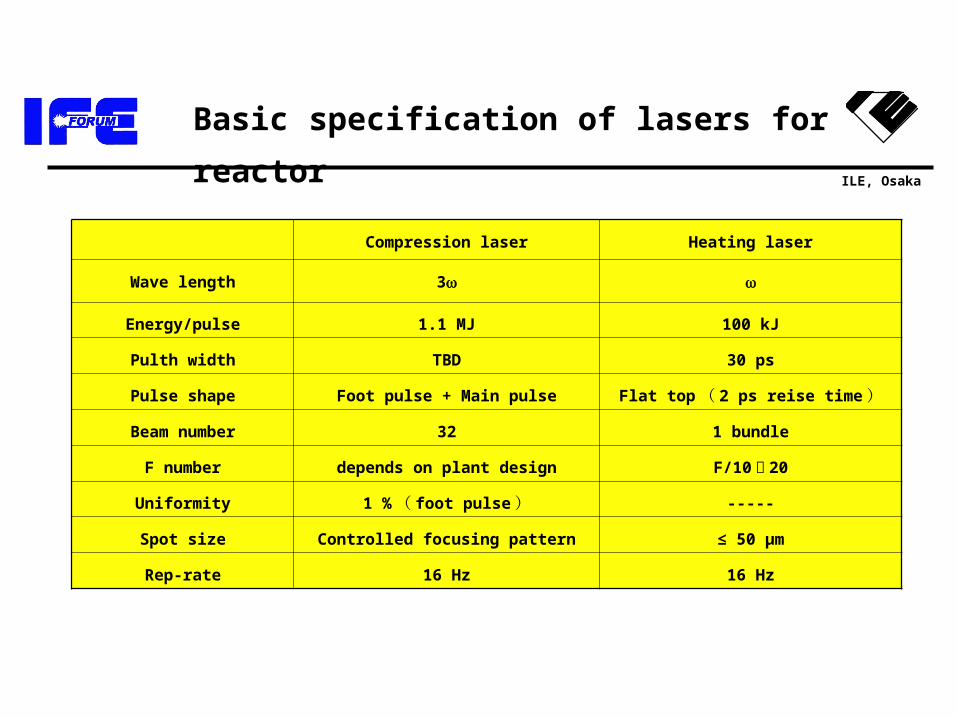
Basic specification of lasers for reactor
Compression laser Heating laser
Wave length 3
Energy/pulse 1.1 MJ 100 kJ
Pulth width TBD 30 ps
Pulse shape Foot pulse + Main pulse Flat top ( 2 ps reise time )
Beam number 32 1 bundle
F number depends on plant design F/10 〜 20
Uniformity 1 % ( foot pulse ) -----
Spot size Controlled focusing pattern ≤ 50 µm
Rep-rate 16 Hz 16 Hz
ILE, Osaka
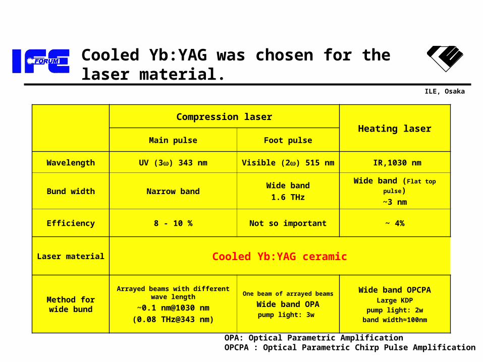
Cooled Yb:YAG was chosen for the laser material.
Compression laserHeating laser
Main pulse Foot pulse
Wavelength UV (3) 343 nm Visible (2) 515 nm IR,1030 nm
Bund width Narrow bandWide band
1.6 THz
Wide band (Flat top pulse)
~3 nm
Efficiency 8 - 10 % Not so important ~ 4%
Laser material Cooled Yb:YAG ceramic
Method for wide bund
Arrayed beams with different wave length
~0.1 nm@1030 nm
(0.08 THz@343 nm)
One beam of arrayed beams
Wide band OPApump light: 3w
Wide band OPCPALarge KDP
pump light: 2w
band width≈100nm
OPA: Optical Parametric AmplificationOPCPA : Optical Parametric Chirp Pulse Amplification
ILE, Osaka
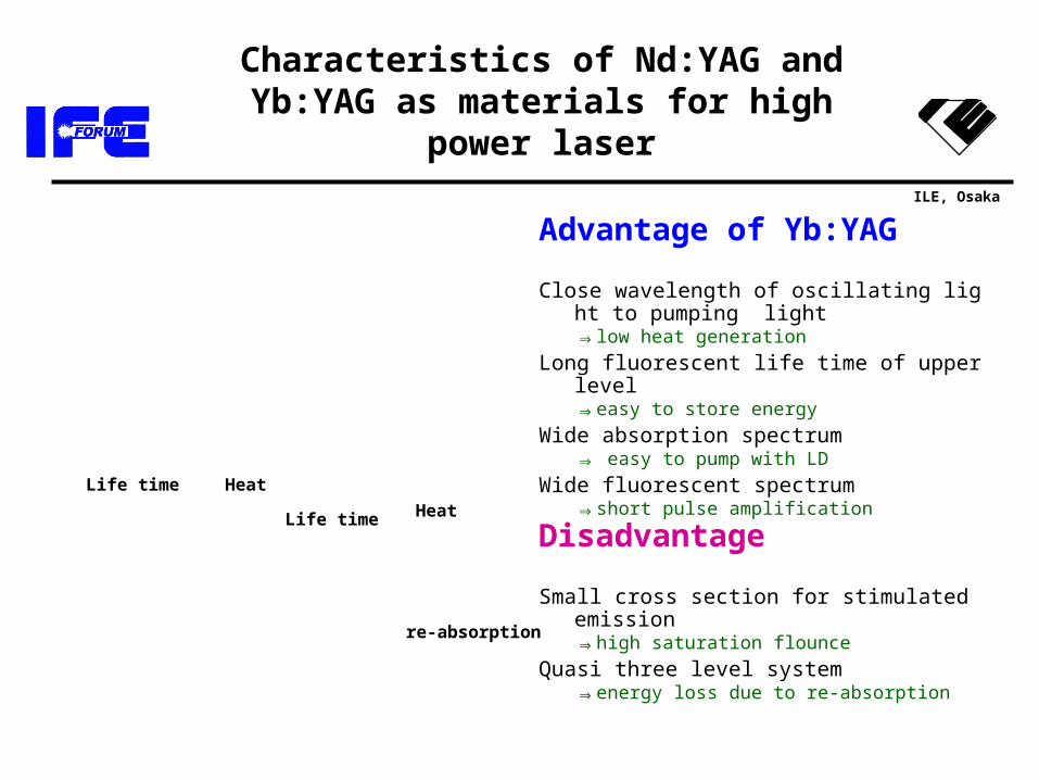
Characteristics of Nd:YAG and Yb:YAG as materials for high power laser
Advantage of Yb:YAG
Close wavelength of oscillating light to pumping light
⇒low heat generationLong fluorescent life time of upper level
⇒easy to store energyWide absorption spectrum
⇒ easy to pump with LDWide fluorescent spectrum
⇒short pulse amplification
Disadvantage
Small cross section for stimulated emission⇒high saturation flounce
Quasi three level system⇒energy loss due to re-absorptio
n
Life time
Life time
re-absorption
Heat
Heat
ILE, Osaka
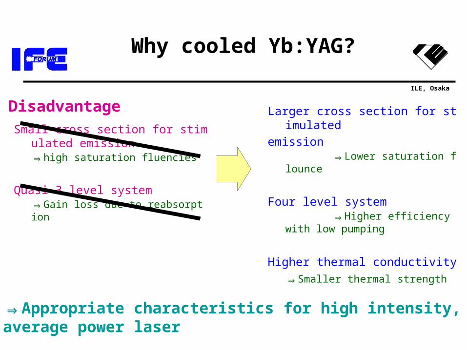
Why cooled Yb:YAG?
Disadvantage
Small cross section for stimulated emission
⇒high saturation fluencies
Quasi 3 level system⇒Gain loss due to reabsorp
tion
Larger cross section for stimulatedemission
⇒Lower saturation flounce
Four level system⇒Higher efficiency with low
pumping
Higher thermal conductivity⇒Smaller thermal strength
⇒Appropriate characteristics for high intensity,average power laser
ILE, Osaka
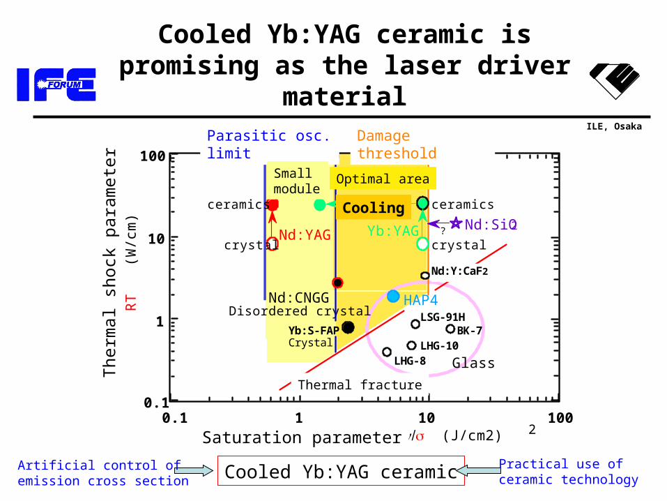
Cooled Yb:YAG ceramic
熱シ
ョッ
クパ
ラメ
ータ
ー
RT
(W
/cm
)
飽和パラメーター h (J/cm2)
1
10
100
0.10.1 1 10 100
望ましい領域
Glass
Yb:S-FAP
熱破壊
Disordered crystal
crystal
Crystal
Nd:CNGG
寄生発振限界
小口径モジュール
Nd:SiO2
LHG-8
LSG-91H
LHG-10BK-7
Yb:YAG
HAP4
Nd:Y:CaF2
光学破壊限界
Nd:YAG
ceramics
crystal
ceramics
?
Cooling
Artificial control ofemission cross section
Practical use ofceramic technology
2Saturation parameter
The
rmal
sho
ck p
aram
eter
Parasitic osc. limit Damage threshold
Thermal fracture
Optimal areaSmallmodule
Cooled Yb:YAG ceramic is promising as the laser driver material
ILE, Osaka
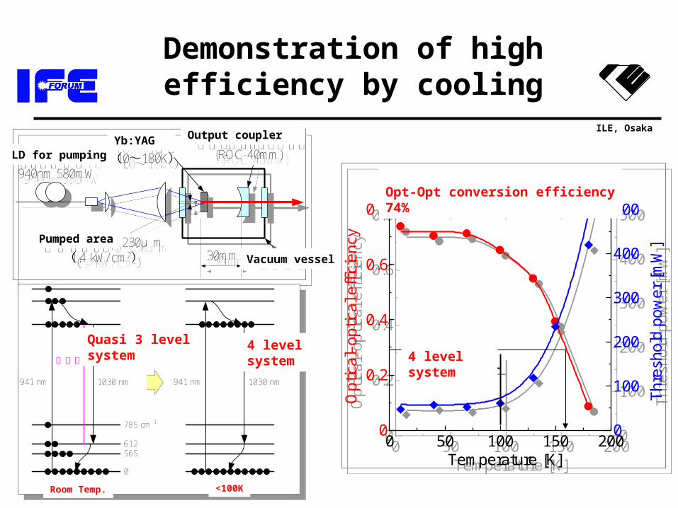
Demonstration of high efficiency by cooling
ファイバ出力LD940nm 580mW
Yb:YAG結晶(10~180K)
アウトプットカップラー(ROC 40mm)
真空容器励起スポット φ 230μ m
(1.4 kW/ cm2) 30mm
ファイバ出力LD940nm 580mW
Yb:YAG結晶(10~180K)
アウトプットカップラー(ROC 40mm)
真空容器励起スポット φ 230μ m
(1.4 kW/ cm2) 30mm
941 nm 1030 nm
785 cm-1
612565
0
941 nm 1030 nm
室温 <100 K
再吸収 4準位系準3準位系941 nm 1030 nm
785 cm-1
612565
0
941 nm 1030 nm
室温 <100 K
再吸収 4準位系準3準位系
0 50 100 150 2000
0.2
0.4
0.6
0.8
0
100
200
300
400
500
Temperature [K]
Thr
esho
ld p
ower
[m
W]
Opt
ical
–opt
ical
eff
icie
ncy
光–光変換効率スロープ効率
4準位領域
74%90%
0 50 100 150 2000
0.2
0.4
0.6
0.8
0
100
200
300
400
500
Temperature [K]
Thr
esho
ld p
ower
[m
W]
Opt
ical
–opt
ical
eff
icie
ncy
光–光変換効率スロープ効率
4準位領域
74%90%
LD for pumpingYb:YAG Output coupler
Vacuum vessel
Pumped area
Opt-Opt conversion efficiency 74%
Quasi 3 levelsystem
4 levelsystem
Room Temp. <100K
4 level system
ILE, Osaka
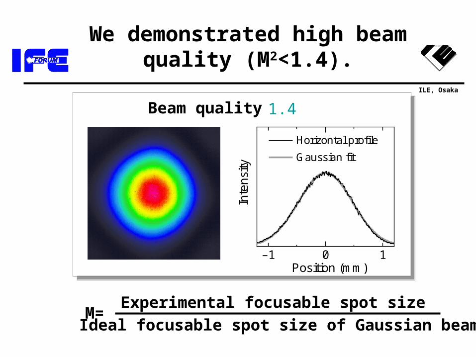
We demonstrated high beam quality (M2<1.4).
–1 0 1Position (mm)
Inte
nsi
ty
Gaussian fit
Horizontal profile
–1 0 1Position (mm)
Inte
nsi
ty
Gaussian fit
Horizontal profile
ビーム品質 M2<1.4
M=Experimental focusable spot size
Ideal focusable spot size of Gaussian beam
Beam quality
ILE, Osaka
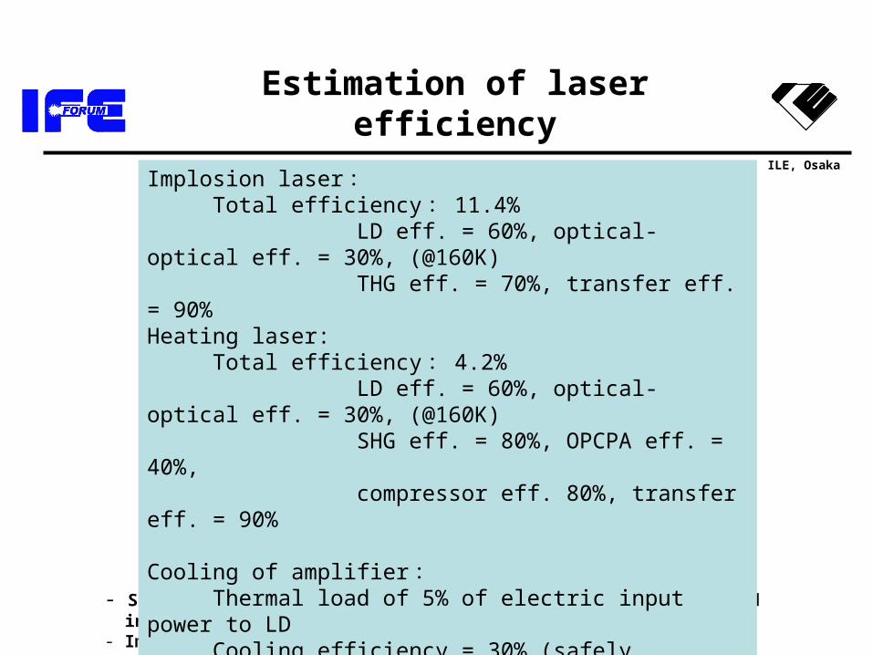
- Supplementary power supply (air conditioner, etc.) is excluded in this estimation.- Improvement of optical-optical eff. is needed.
Estimation of laser efficiency
Implosion laser : Total efficiency : 11.4% LD eff. = 60%, optical-optical eff. = 30%, (@160K) THG eff. = 70%, transfer eff. = 90%Heating laser: Total efficiency : 4.2% LD eff. = 60%, optical-optical eff. = 30%, (@160K) SHG eff. = 80%, OPCPA eff. = 40%, compressor eff. 80%, transfer eff. = 90%
Cooling of amplifier : Thermal load of 5% of electric input power to LD Cooling efficiency = 30% (safely assumed, 60%@160K)
Total efficiency of laser system includig refriierator= 8.7% (9.2%)
ILE, Osaka
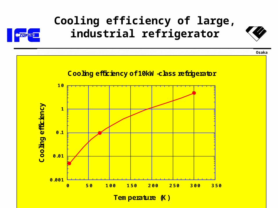
Cooling efficiency of large, industrial refrigerator
0. 001
0. 01
0 .1
1
1 0
0 5 0 1 0 0 1 5 0 2 0 0 2 5 0 3 0 0 3 5 0
Co
olin
g e
ffic
ien
cy
Temperature (K)
Cooling efficiency of 10kW-class refrigerator
ILE, Osaka
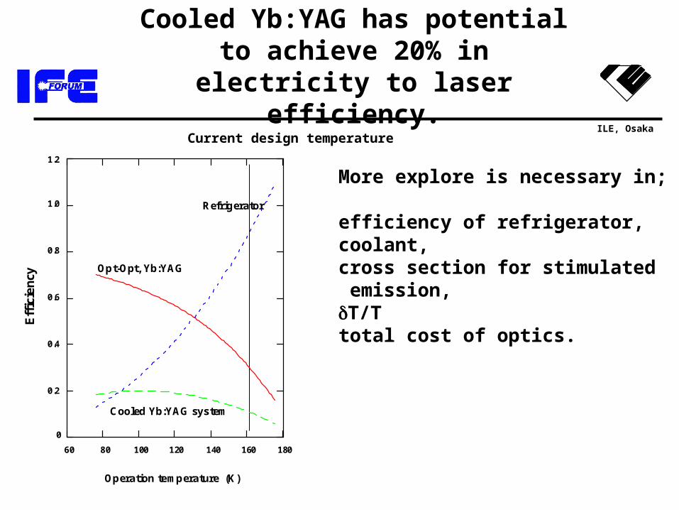
Cooled Yb:YAG has potential to achieve 20% in electricity to laser
efficiency.
More explore is necessary in;
efficiency of refrigerator,coolant,cross section for stimulated emission,T/Ttotal cost of optics.
Current design temperature
60 80 100 120 140 160 180
0
0.2
0.4
0.6
0.8
1.0
1.2
Operation temperature (K)
Eff
icie
ncy
Opt-Opt, Yb:YAG
Refrigerator
Cooled Yb:YAG system
ILE, Osaka
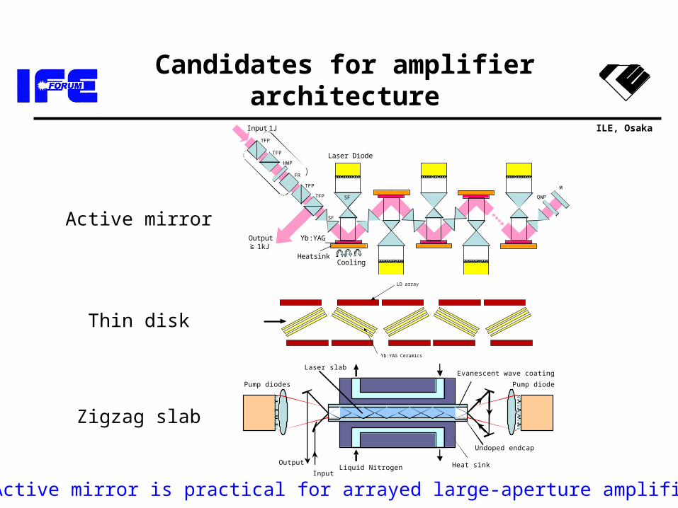
LD array
Yb:YAG Ceramics
Input
OutputLiquid Nitrogen
Pump diodes
Laser slabEvanescent wave coating
Heat sink
Undoped endcap
Pump diodes
Active mirror
Thin disk
Zigzag slab
Active mirror is practical for arrayed large-aperture amplifier.
Candidates for amplifier architecture
TFP
TFP
FR
HWP
TFP
TFP
Laser Diode
SF
SF QWP
Yb:YAG
Cooling
M
Input 1J
Output≧ 1kJ
Heatsink
ILE, Osaka
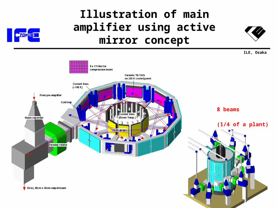
Illustration of main amplifier using active mirror concept
8 beams
(1/4 of a plant)
ILE, Osaka
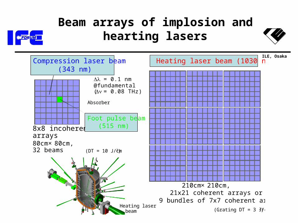
Beam arrays of implosion and hearting lasers
Compression laser beam(343 nm)
Absorber
8x8 incoherentarrays
Heating laser beam (1030 nm)
Foot pulse beam(515 nm)
Heating laser beam
80cm× 80cm,32 beams
= 0.1 nm@fundamental( = 0.08 THz)
(Grating DT = 3 J/cm2)
(DT = 10 J/cm2)
210cm× 210cm,21x21 coherent arrays or
9 bundles of 7x7 coherent arrays
ILE, Osaka
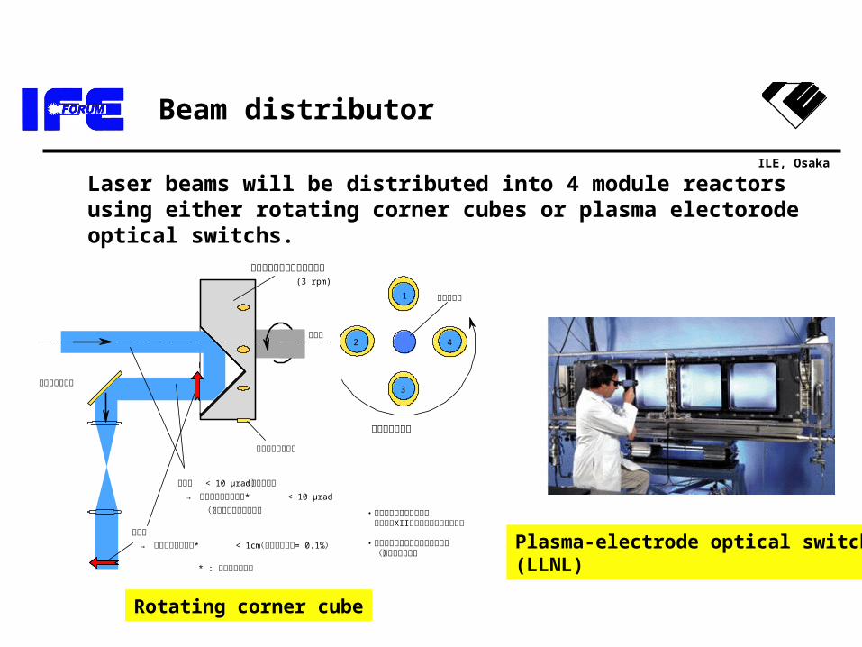
Beam distributor
・コーナーキューブミラー: XII 既設激光 号光路長調整機構に使用
・ハニカム構造ミラーによる軽量化 (試作段階完了)
1
3
分配ビーム配置
回転コーナーキューブミラー
回転軸
蹴り出しミラー
入射ビーム
平行度 < 10 µrad(工作精度)
→ *ポインティング精度 < 10 µrad
(歳差運動の影響無し)
像転送 → *センタリング精度 < 1cm = 0.1%(回転周期変動 )
* : 最終集光系上で
回転速度モニター
42
(3 rpm)
Rotating corner cube
Plasma-electrode optical switch(LLNL)
Laser beams will be distributed into 4 module reactors using either rotating corner cubes or plasma electorode optical switchs.
ILE, Osaka
Outline
• Introduction• Chamber and plant• Laser system• Fueling system
– Target design– Status of fabrication– Batch process
ILE, Osaka
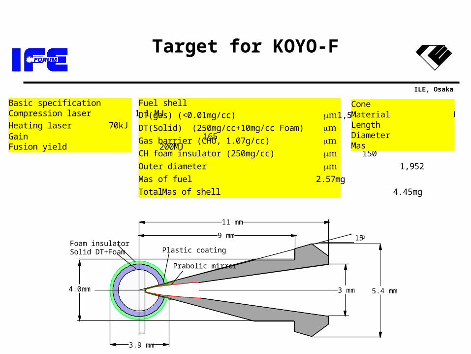
Target for KOYO-F
Fuel shell
DT(gas) (<0.01mg/cc) 1,500 mDT(Solid) (250mg/cc+10mg/cc Foam) 300 mGas barrier (CHO, 1.07g/cc) 2 mCH foam insulator (250mg/cc) 150 mOuter diameter 1,952 mMas of fuel 2.57mg
Total Mas of shell 4.45mg
Basic specification Compression laser 1.1 MJ
Heating laser 70kJ Gain 165 Fusion yield 200MJ
Cone Material Li17Pb83 Length 11mm Diameter 5.4 mm Mas 520 mg
3.9 mm
15o9 mm
11 mm
5.4 mm3 mm4.0 mm
Plastic coating
Prabolic mirror
Foam insulator Solid DT+Foam
ILE, Osaka
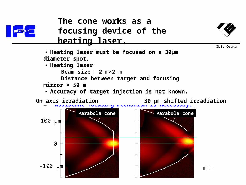
コーン軸上集光
100 µm
-100 µm
0
集光点30µmシフト
パラボラコーンパラボラコーン
・ Heating laser must be focused on a 30µm diameter spot.・ Heating laser Beam size: 2 m×2 m Distance between target and focusing mirror ≈ 50 m・ Accuracy of target injection is not known.
→ Assistant focusing mechanism is necessary.
The cone works as a focusing device of the heating laser.
スラブ計算
On axis irradiation 30 m shifted irradiation
Parabola coneParabola cone
ILE, Osaka
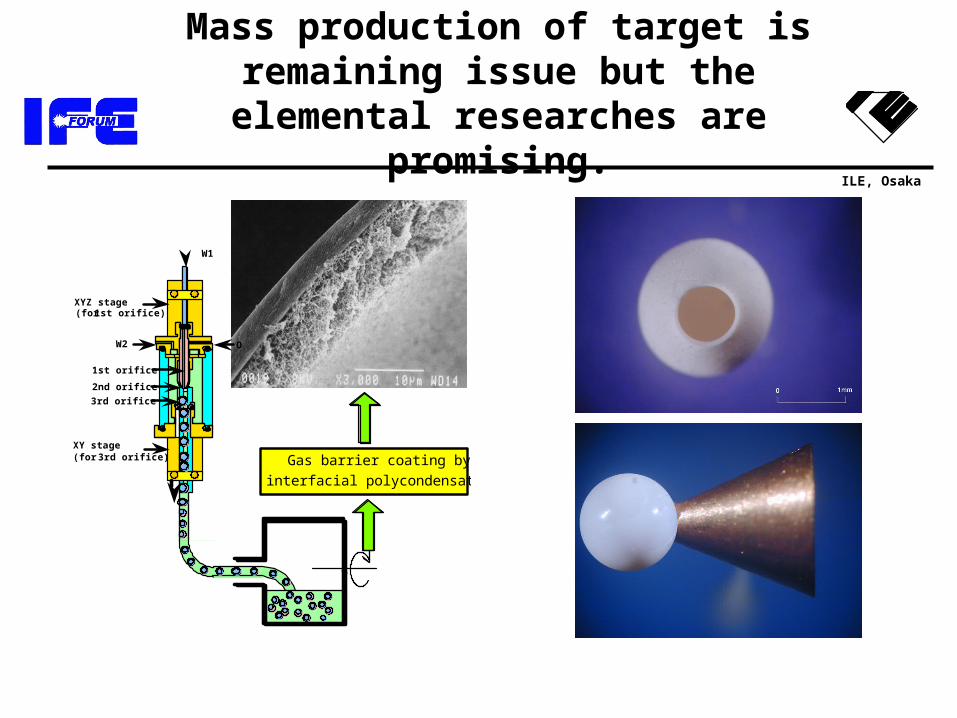
Mass production of target is remaining issue but the elemental
researches are promising.
OW2
1st orifice
2nd orifice
W1
XYZ stage(for 1st orifice)
3rd orifice
XY stage(for 3rd orifice) Gas barrier coating by
interfacial polycondensation
ILE, Osaka
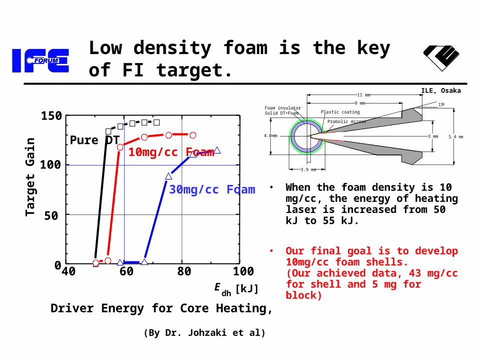
Low density foam is the key of FI target.
• When the foam density is 10 mg/cc, the energy of heating laser is increased from 50 kJ to 55 kJ.
• Our final goal is to develop 10mg/cc foam shells.(Our achieved data, 43 mg/cc for shell and 5 mg for block)40 60 80 1000
50
100
150
Targ
et
Gain
Driver Energy for Core Heating, E
dh [kJ]
Pure DT10mg/cc Foam
30mg/cc Foam
(By Dr. Johzaki et al)
3.9 mm
15o9 mm
11 mm
5.4 mm3 mm4.0 mm
Plastic coating
Prabolic mirror
Foam insulator Solid DT+Foam
ILE, Osaka
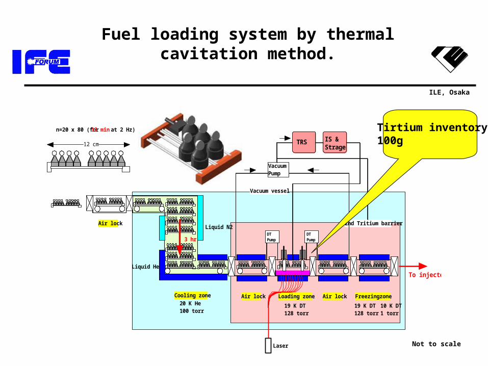
Fuel loading system by thermal cavitation method.
n=20 x 80 (for 13 min at 2 Hz)
12 cm
Air lock
Air lockAir lockCooling zone Freezing zoneLoading zone
Liquid N2
Liquid He
20 K He 100 torr
19 K DT 128 torr
19 K DT 128 torr
10 K DT 1 torr
DT Pump
DT Pump
2nd Tritium barrier
Vacuum vessel
3 hr
Vacuum Pump
TRS IS & Strage
To injector
Laser Not to scale
Tirtium inventory100g
ILE, Osaka
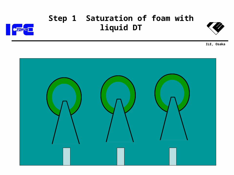
Step 1 Saturation of foam with liquid DT
ILE, Osaka
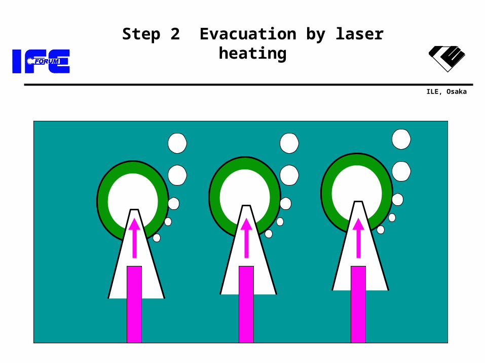
Step 2 Evacuation by laser heating
ILE, Osaka
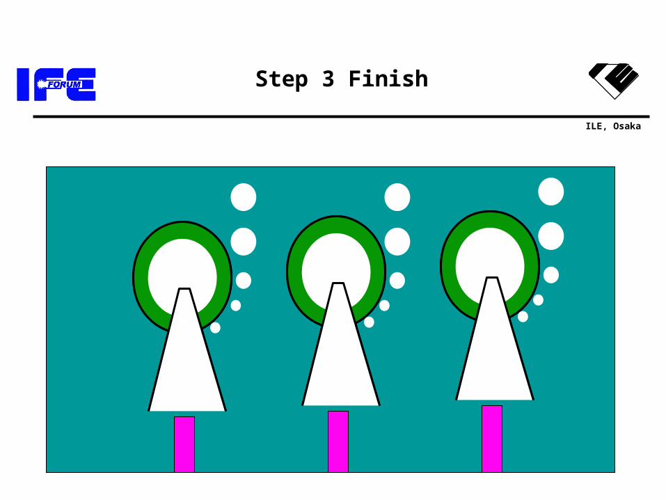
Step 3 Finish
ILE, Osaka
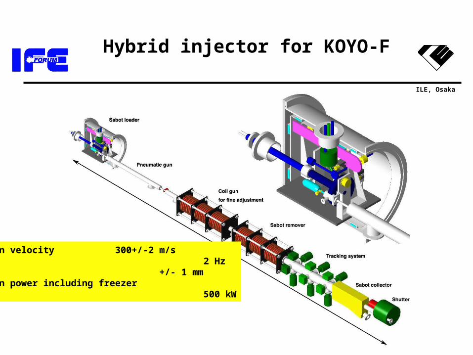
Hybrid injector for KOYO-F
Injection velocity 300+/-2 m/sRep rate 2 HzPointing +/- 1 mmOperation power including freezer 500 kW
ILE, Osaka
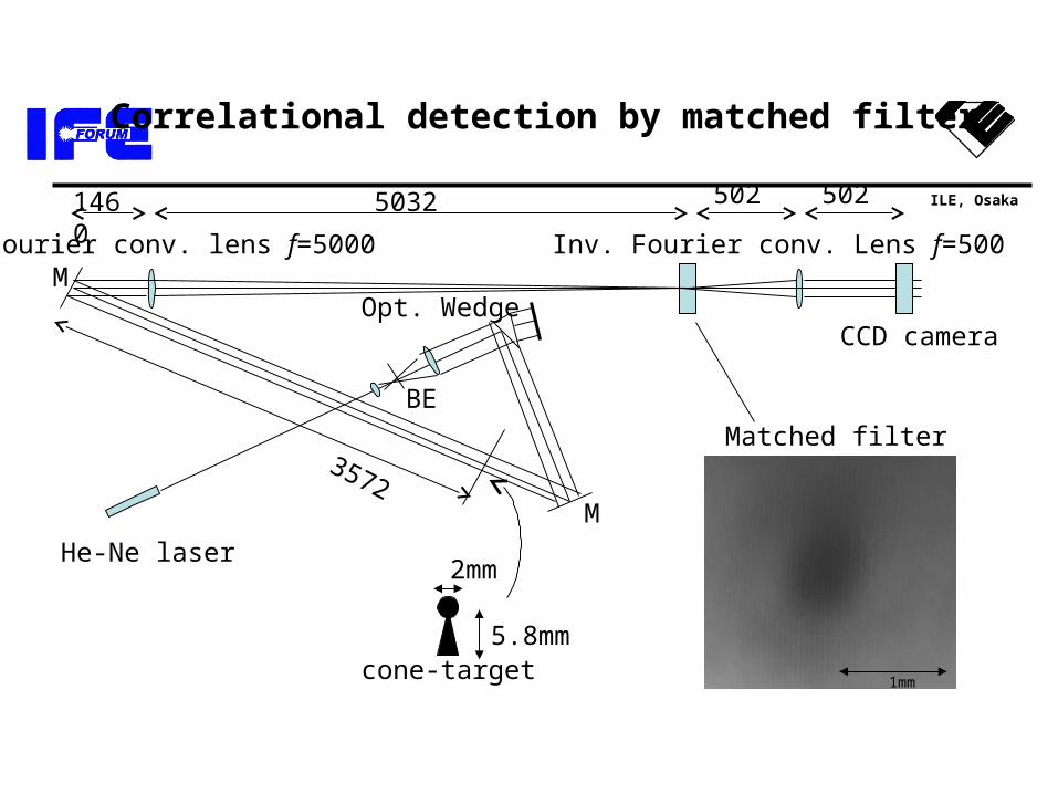
Correlational detection by matched filter
Opt. Wedge
He-Ne laser
M
MFourier conv. lens f=5000
BE
Matched filter
CCD camera
Inv. Fourier conv. Lens f=500
1460 5032 502 502
3572
5.8mm
2mm
cone-target 1mm
ILE, Osaka
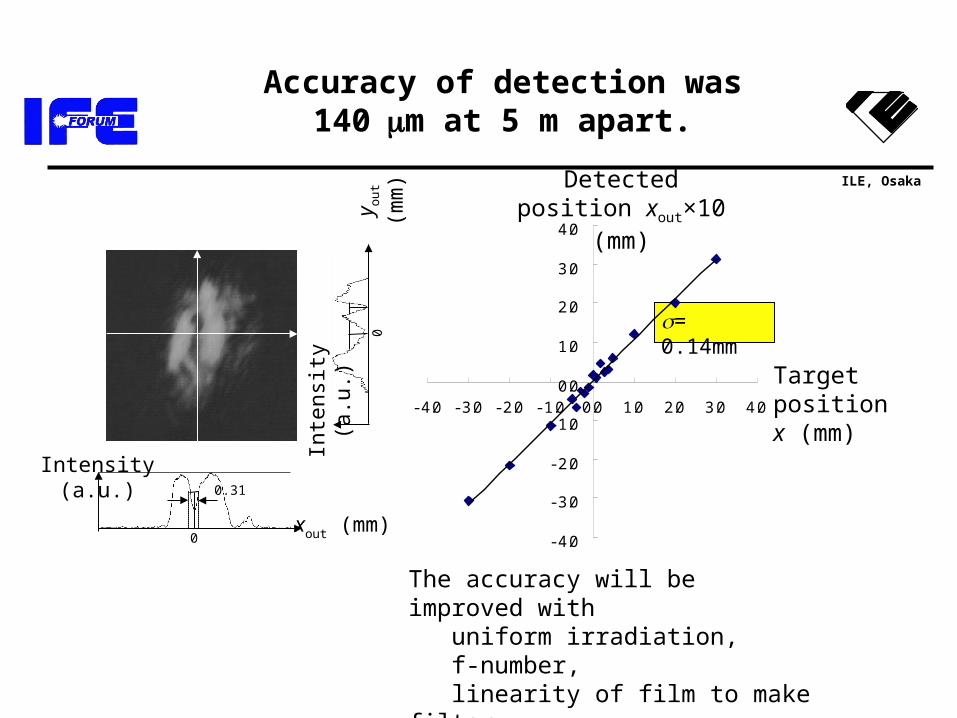
Accuracy of detection was 140m at 5 m apart.
Intensity (a.u.)
xout (mm)0
0.31
Inte
nsit
y (a
.u.)
y out (
mm
)0
- 4.0
- 3.0
- 2.0
- 1.0
0.0
1.0
2.0
3.0
4.0
- 4.0 - 3.0 - 2.0 - 1.0 0.0 1.0 2.0 3.0 4.0
= 0.14mm
Target position x (mm)
Detected position xout×10 (mm)
The accuracy will be improved with uniform irradiation, f-number, linearity of film to make filter.
ILE, Osaka
Summary
– 1) We have examined the design windows and the issues of the fast ignition laser fusion power plants. ~1200 MWe modular power plants driven at ~16 Hz
– 2) For laser driver we have considered the DPSSL design using the Yb:YAG ceramic operating at low temperature (100~200K).
– 3) We have proposed the free fall cascade liquid chamber for cooling surface quickly enough to several Hz pulses operation by short flow path. The chamber ceiling and laser beam port are protected from the thermal load by keeping the surface colder to enhance condensation of LiPb vapor.
– 4)For exhausting DT gas mixed with LiPb vapor we have designed diffusion pumps using Pb (or LiPb) vapor with effective exhaust velocity about 8 m3/s DT gas.
– 5) For protecting final optics we have considered the combinations of rotary shutters for stopping neutral vapors and magnets for eliminating ions.
ILE, Osaka
Future work
• Core plasma– Specification for lasers– Control of isentrope
• Laser– Frequency conversion– Phase control
• Reactor system– Stability of surface flow– Accuracy of injection– Tracking and beam steering– System integration
• Target– Low density foam– Accuracy ±1%