Embed Size (px)
Citation preview

Illinois Space Society
Student Launch 2015-2016
Maxi-MAV Critical Design Review
January 15, 2016
University of Illinois Urbana-Champaign Illinois Space Society
104 S. Wright Street
Room 321D
Urbana, Illinois 61801

1
Contents Acronym Dictionary ..................................................................................................................... 4
General Information ........................................................................................................................ 5
Managers ..................................................................................................................................... 5
Major Subteam 1: Structures and Recovery ............................................................................... 5
Major Subteam 2: AGSE ............................................................................................................ 5
Minor Subteams .......................................................................................................................... 5
NAR Section ............................................................................................................................... 6
I) Summary of CDR report ............................................................................................................. 7
Launch Vehicle Summary........................................................................................................... 7
Payload Summary ....................................................................................................................... 7
II) Changes made since PDR .......................................................................................................... 8
Changes to Structures and Recovery .......................................................................................... 8
Changes to AGSE ....................................................................................................................... 8
PDR Feedback ............................................................................................................................ 8
III) Vehicle Criteria......................................................................................................................... 9
Design and Verification of Launch Vehicle ............................................................................... 9
Flight Reliability and Confidence ........................................................................................... 9
Mission Statement ................................................................................................................. 10
Requirements ........................................................................................................................ 10
Mission Success Criteria ....................................................................................................... 10
Major Milestone Schedule .................................................................................................... 11
System Design Review ............................................................................................................. 11
Booster System ..................................................................................................................... 11
Subsystem Descriptions ............................................................................................................ 16
Motor Subsystem .................................................................................................................. 16
Fin Subsystem ....................................................................................................................... 18
Avionics/Payload Bay Subsystem ........................................................................................ 20
Performance Characteristics ................................................................................................. 24
Vehicle and Recovery Requirements ........................................................................................ 25
Approach to Workmanship ................................................................................................... 30
Test Descriptions and Results ............................................................................................... 31
Planning of Manufacturing, Verification, Integration and Operations ................................. 34
Integrity of Design ................................................................................................................ 35

2
Subscale Flight Results ............................................................................................................. 47
First Flight (Aerotech F40) ................................................................................................... 47
Second Flight (Aerotech G54) .............................................................................................. 49
Subscale flight data’s impact on the design of the full-scale launch vehicle. ....................... 51
Recovery Subsystem ................................................................................................................. 51
Parachute, harnesses, bulkheads, and attachment hardware. ................................................ 51
Recovery System Attachment Techniques ........................................................................... 53
Parachute Deployment Process ............................................................................................. 54
Electronic Components ......................................................................................................... 55
Kinetic Energy at Significant Phases .................................................................................... 57
Safety and Failure Analysis .................................................................................................. 58
Mission Performance Predictions ............................................................................................. 59
Mission Performance Criteria ............................................................................................... 59
Flight Profile Simulations ..................................................................................................... 59
Validity of Analysis, Drag Assessment, and Scale Modeling Results. ................................ 63
Stability Margin .................................................................................................................... 63
Payload Integration ................................................................................................................... 66
Integration Plan ..................................................................................................................... 66
Launch concerns and operation procedures .............................................................................. 67
Comprehensive Checklist ..................................................................................................... 70
Safety and Environment (Vehicle and Payload) ....................................................................... 73
Safety Officer ........................................................................................................................ 73
NAR Personnel Duties .......................................................................................................... 74
Hazard Recognition .............................................................................................................. 74
Law Compliance ................................................................................................................... 75
Motor and Energetic Device Handling ................................................................................. 75
Preliminary Hazard Analysis ................................................................................................ 75
Environmental Concerns ....................................................................................................... 80
IV) AGSE/Payload Criteria .......................................................................................................... 86
Selection, Design, and Verification of Payload ........................................................................ 86
System Review (include sequential process order) .............................................................. 86
Subsystem Overview ................................................................................................................ 88
Drawings, analysis, test results, and integrity of design ....................................................... 88
System-Level Functional Requirements ............................................................................... 97

3
Approach to workmanship .................................................................................................... 99
Planned testing .................................................................................................................... 100
Manufacturing and Assembly ............................................................................................. 104
Integration Plan ................................................................................................................... 105
Precision of Instrumentation and Repeatability .................................................................. 105
Electronics Subsystem ........................................................................................................ 106
Safety and Failure Analysis ................................................................................................ 109
Payload Concept Features and Definition - ............................................................................ 113
Creativity, Originality, and Uniqueness.............................................................................. 113
Suitable level of challenge .................................................................................................. 113
Science Value.......................................................................................................................... 113
VI) Project Plan........................................................................................................................... 114
Show status of activities and schedule .................................................................................... 114
Budget plan ......................................................................................................................... 114
Funding Plan ....................................................................................................................... 117
Timeline .............................................................................................................................. 118
Educational Engagement Plan ............................................................................................ 120
V) Conclusion ............................................................................................................................. 121
Appendix A ................................................................................................................................. 122
Appendix B ................................................................................................................................. 125
Appendix C ................................................................................................................................. 126
Appendix D ................................................................................................................................. 129
Appendix E ................................................................................................................................. 131

4
Acronym Dictionary
AGSE: (Autonomous Ground Support Equipment) This is a combination of crane, rail, and
ignition systems used to robotically accomplish the mission goals.
CAD: (Computer Aided Design) Computer software that allows the design, assembly, and
annotation of rocket and AGSE components.
CDR: (Critical Design Review) A design review that shows that the design is ready for full scale
production and fabrication.
CFC: (Chlorofluorocarbons) Commonly used in aerosol cans until the 1980’s and were
determined to be damaging to the ozone layer.
CIA: (Central Illinois Aerospace) A local rocketry club that assists the team with test launching
the rockets. They also provide their expertise during the design and building phase of the
competition.
ISS: (Illinois Space Society) The parent group of the team competing in the Student Launch
competition.
LPG: (Liquid Propane Gas) The most common propellant used in spray paint cans, and is less
harmful to the ozone than CFC’s.
NAR: (National Association of Rocketry) Governs the use of high powered rocketry to ensure the
safety of the participants, spectators, and the environment.
PDR: (Preliminary Design Review) A design review that shows a feasible concept that will be the
subject of future work.

5
General Information Team Leader
Ian Charter, Project Manager
Phone: (815) 278-1294
Email: [email protected]
Safety Officer
Andrew Koehler
Managers
Project Manager: Ian
Safety Officer: Andrew
Structures and Recovery Manager: Stephen
AGSE Manager: Ben
Webmaster: Lui
Educational Outreach Director: Chris
Major Subteam 1: Structures and Recovery The first main subteam of about 10 students is the Structures and Recovery Team. This
team will be responsible for the design and construction of the vehicle, including systems for
parachute deployment and sample containment. The Structures and Recovery manager is Stephen.
Brian, Alli, Andrew, and David are key technical members for the Structures and Recovery teams.
Specifically, Brian is responsible for the design of the vehicle, and Andrew is responsible for
construction procedures. Alli is charged with management of the recovery systems, and David is
in charge of the sample canister and hatch systems.
Major Subteam 2: AGSE The second major subteam is the Autonomous Ground Support Equipment (AGSE) Team.
This team will be responsible for the design and construction of a robotic system to contain the
sample within the vehicle, as well as systems to erect the rocket from the horizontal position and
install the motor igniter. Ben is the AGSE manager. Brandon, Nick, Chris, and Alex are key
technical personnel for the AGSE systems. Ben is responsible for the compatibility between AGSE
components, and Brandon is in charge of the sample retrieval system. Alex is charged with
managing the ignition system, Nick is in charge of the lifting system, and Chris is in charge of
mass requirements.
Minor Subteams Minor subteams of around 5 students will be responsible for web design, safety planning,
and educational outreach. Each student on these subteams is also a member of either the AGSE or
Structures and Recovery subteams. Lui will manage the web design subteam, Andrew the safety
subteam, and Chris will manage the educational outreach activities.
In general, subteam managers are charged with organizing their respective teams, planning
necessary meetings, and overseeing progress on technical designs. That said, every team member
including managers will play a role in the technical design of their assigned systems. Although
key technical members are listed for the major subteams, whenever possible technical work will
be divided equally between all team members. The team’s goal is to draw on the knowledge of

6
past members, while also giving new members hands-on experience with the design and build
process.
NAR Section The ISS Tech Team will be working with members of Central Illinois Aerospace (CIA) to
facilitate test launches and review system designs. Specifically, Mark Joseph will be the NAR
mentor for the ISS Tech Team. CIA is section 527 of the National Association of Rocketry. The
CIA organizes launches every other week at several locations close to the university, depending
on the time of year and launch field conditions.
Figure 1. Complete CAD drawing of the rocket and AGSE system

7
I) Summary of CDR report
Launch Vehicle Summary It was the team’s decision to design, build, and implement a flight vehicle from raw
materials and to individually pick out parts rather than build from a kit. The vehicle will be a single
stage rocket with one motor and a standard dual deploy recovery system. The vehicle for this
project will measure 90.25 inches from the aft end of the motor retainer to the tip of the nose cone.
The vehicle body will be constructed of 4.014 inch diameter Blue Tube, which has an inner
diameter of 3.9 inches. The current design mass of the vehicle is 22.536 pounds, which includes 2
pounds of unspecified mass as margin to allow for any mass growth as construction begins.
The selected motor is the Aerotech K1000T reloadable 75mm motor with a total impulse
of 561.26 lbf-s (2511.5 N-s). The vehicle will launch on an 8 foot long, size 1515 launch rail.
The recovery system for this vehicle is based off of a standard dual deploy system: a smaller
drogue and larger main parachute. At apogee, a 15” elliptical drogue parachute manufactured by
Fruity Chutes will deploy from the booster section. At 450 feet above ground level, an Iris Ultra
72” compact main parachute will deploy from the upper airframe. Onboard altimeters will be used
to deploy the main and drogue parachutes by triggering a black powder charge that pressurizes the
body tube, therefore separating it from another airframe. Tubular Kevlar 1⁄2” shock cord is used
to attach all parachutes to the vehicle.
This combination of parachute sizes and deployment altitudes will ensure that each section
of the rocket will reach the ground with less than 75 ft-lbf of kinetic energy but stay within the
2,500 ft maximum drift distance set by NASA.
Payload Summary The team will be building off of last year’s design, keeping a similar rail and igniter
insertion system. An actuator will be used to raise up the rail system, with a limit switch at the
base of the launch pad so that when the rail is 5 degrees off of the vertical, the switch will be
triggered stopping the actuator. The igniter system will use a similar actuator, with a “Z” shaped
piece and a thin, wooden rod attached to the opposite end of the piece, with the igniter fashioned
onto the end. The actuator will raise the Z-piece and, in turn, raise the igniter. Screwed onto the
blast plate will be a guide cone that the igniter will rise through to more accurately aim the igniter
into the rocket.
The team has designed a robotic crane-like mechanism to retrieve the payload. The crane
is a three segment structure, with 360° rotation and a vertical arm fashioned at the end of a
horizontal beam jutting outward from the base of the structure. At the bottom of the vertical arm
is an electromagnet holding onto a curved piece cut from the rocket’s body tube, with clips along
the underside. The crane will rotate and pick up the payload by pressing these clips onto said
payload. The arm shall then rotate over to the rocket and shut off the electromagnet, releasing the
payload and hatch door. Finally, the hatch will be sealed with small permanent magnets attached
to the rocket and bay door, along with a tubular latch fastened to the inside of the rocket and will
seal itself to a small, block on the hatch door.

8
II) Changes made since PDR
Changes to Structures and Recovery In order to optimize the volume of the AGSE system and to utilize portions of the current
AGSE’s ignition system, the team has switched to using an Aerotech K1000T-P motor. The
K1000T is shorter and wider than the Aerotech K828FJ used through PDR. The comparative
additional weight and power of the motor led to adjustments to the fin geometry in order to
maintain a target 5,280 ft altitude despite the change in motor. Additionally, the size of the main
parachute was increased to 72 inches in order to stay within the kinetic energy requirements of the
competition.
In order to stay within a maximum drift distance of 2,500 feet the team shrunk the drogue
parachute from a 24 inch elliptical to a 15 inch elliptical manufactured by Fruity Chutes. This
change drastically reduces drift while still allowing the main parachute to deploy at a safe descent
speed. Additionally, the main parachute will now deploy at 450 ft altitude rather than 500 ft in
order to keep the drift within 2,500 ft even in 20 mph cross winds.
Following further testing and consideration, the active drag subsystem was scrapped in
favor of relying on further analysis and vehicle/motor characteristics to get within the target
altitude of 5,280 feet.
Changes to AGSE The main change to the AGSE system following the completion of the Preliminary Design
Review is the implementation of additional support in attaching the hatch door to the vehicle. Now,
instead of relying solely on magnets along the door, the team will also have a door-like latch on
the inside of the rocket, near where the hatch door opening will be. This further ensures that the
hatch will not release during flight.
So as to reduce the weight of the entire system, the team has opted to remove sections of
the launch pad. This is the same launch pad that has been used in the past for all the launches.
Because of this, it has visible residue, which can be used to mark where the blast will strike and
where sections of the launch pad can be cut without worry of damaging the system below, or threat
of a ground fire. Therefore, the team believes that the modifications maintain the integrity of the
design, while decreasing system weight.
PDR Feedback Listed drift values exceed 2,500 ft. Please make the necessary adjustments to reduce total
drift. Drogue parachute was shrunk from 24 inches to 15 inches in diameter and the deployment
of the main parachute will now occur at 450 feet in order to keep the drift within 2,500 ft even in
20 mph winds.
Please be sure to reinforce the area around the payload hatch door. By removing material,
you are reducing the strength of the body tube. In addition, how will you lock the hatch
during flight?
The holes have been significantly reduced in order to minimize the amount of Blue Tube
removed. Bulkheads are placed on either side of the opening in the coupler to provide structural
integrity to that section of the vehicle. The edges of the opening will be rounded in order to lessen
the stress at those corners.

9
A pair of Union 2648 mortice latches will be installed and compliment the set of magnets
to lock the hatch during flight.
The black powder charges presented appear too large for your rocket. How did you calculate
them? Can you verify that these charge sizes are accurate?
Black powder charge values have been updated following consultation with the team
mentor and utilization of online resources. Final sizing of ejection charges will take place
following testing of recovery equipment.
The recovery harness lengths listed are thin. When constructing rockets of this size, harness
thicknesses of 1/2" is the recommended minimum.
½” tubular Kevlar will be utilized for both shock cords.
Can your drag flaps open/fail asymmetrically? If so, how will you mitigate this failure?
Active drag is no longer a subsystem on the rocket.
The simulation shows that the rocket will be flying in the transonic region. Does your team
have any experience with building supersonic rockets?
The team mentor and the rocketry organization he is a member of have a vast amount of
experience with transonic and supersonic rockets that the team can draw on in order to ensure that
the rocket is structurally sound enough to deal with these design issues.
According to the CAD model the AGSE is too long. What can be done to reduce this length?
To reduce this, the launch rail was shortened from a 12ft to 8ft. The rocket will still launch
with a safe exit rail velocity of 73.3 ft/s.
III) Vehicle Criteria
Design and Verification of Launch Vehicle
Flight Reliability and Confidence
It is important that the reliability and confidence of the flight vehicle's design is mature.
The hand calculations, coded simulations, OpenRocket simulations, and RockSim simulations that
the team conducted of the predicted flight profile all demonstrate the maturity of the flight vehicle's
design. The team is highly confident in the design of the vehicle. Team members met for an
average of four hours per week, and the design was developed among team members throughout
this time period. The design has been overseen and reviewed by team members with significant
rocketry experience and by the team’s NAR mentor.
The subscale launch also played a major role in the team’s confidence. During the subscale
building process, team members were able to get hands on experience in building a high powered
rocket. This makes the team more certain in constructing the competition vehicle knowing the
team members have experience. Some of the team members attended the subscale launch where
they were able to observe the subscale rocket being launched a number of times.

10
Additionally, the team has been able to learn from the past failures and successes of other
teams due to former experience in the competition. ISS has competed in this competition six times,
giving the current team access to a number of old design documents and reports. Critical parts of
the rocket have previously been used by ISS teams and local rocketry clubs. The team believes the
current design defines an advanced system for completing the mission requirements, without
sacrificing confidence in flight safety and reliability.
The vehicle details were continuously analyzed and redefined to achieve the best possible
design meeting all mission requirements for the project. Although changes are always expected in
the final design and construction processes, the team believes the vehicle defined within this report
is more than sufficient to meet or exceed all project requirements.
Mission Statement
“The mission of the Illinois Space Society Student Launch Team is to safely launch and
recover a reusable high power rocket simulating a Mars Sample Return. This includes design and
construction of an Autonomous Ground Support Equipment system to simulate the loading of a
Martian soil sample and the vehicle launch procedures. The vehicle will be tracked and recovered
after launch. The vehicle will launch to 5,280 feet at which point the drogue will deployed,
followed by the main at 450 feet above ground. The vehicle shall be designed to be reusable upon
recovery, and all components shall land with less than 75 ft-lbf of kinetic energy.”
Requirements
Official project requirements and their respective design features and verification methods
are given in the Vehicle Requirement table of this report. However the team has determined several
unofficial requirements to serve as project goals. Many of these are closely related to official
requirements.
1.) The vehicle must conform to the highest safety standards at all times.
2.) The vehicle shall attain a maximum altitude of 5,280 ft.
3.) The vehicle shall be highly reusable, such that the ISS may recreationally launch the
vehicle with minimum effort upon competition completion.
4.) The vehicle shall be able to function both with the custom AGSE system, as well as a
standard high power rocketry launch rail configuration.
5.) The vehicle shall have a visually appealing design, reflecting the months of extreme
effort dedicated to its design and construction.
6.) The vehicle design and construction shall serve as a high level learning experience for
team members, providing all team members with significant crucial experience in the real
world design and engineering process.
7.) The vehicle design must be well defined and reports shall be given with the highest
amount of detail possible.
Mission Success Criteria
The team will consider the mission a success if the vehicle fulfills all NASA requirements
and if superior safety standards are maintained throughout the project. During the build process
and launch procedures, mission success will depend heavily on team members following all safety
standards laid out later in this document. Minimizing safety risks for team members and observers
is considered critical for success in the competition. On competition day, the rocket should secure
the sample in its payload bay, launch to an apogee of 5,280 feet, and then land safely at a reasonable
distance from the launch pad. The rocket’s recovery system will be deemed successful if the drogue

11
and main parachutes deploy successfully and if the onboard altimeters record relevant data
throughout the flight.
Major Milestone Schedule
Table 1. Major Milestone Schedule
Date Milestone
August 30, 2015 Team compiled and established goals
September 11, 2015 Proposal documentation submitted
November 6, 2015 Preliminary Design Review documentation submitted
November 16, 2015 PDR video teleconference presentation delivered
December 9, 2015 Subscale build begins
December 19, 2015 Subscale is launched and data gathered
January 15, 2016 Critical Design Review documentation submitted
January 18, 2016 Begin finalizing building instructions
January 20, 2016 All parts to be inventoried & inspected, build plan reviewed
January 22, 2016 CDR video teleconference presentation
February 27, 2016 Component testing
March 5, 2016 Full Scale test flight, test recovery system
March 14, 2016 Flight Readiness Review documentation due
April 14, 2016 Launch Readiness Review
April 16, 2016 Launch full scale flight vehicle
April 17, 2016 Review & reflect on flight results and feedback
April 29, 2016 Post Launch Assessment Review document due
System Design Review
Booster System
The booster system includes everything contained within the rocket’s lower body tube. It
includes complete subsystems for the motor, fins, and rail buttons, and houses the first (drogue)
recovery stage. Here a generalized description of each subsystem will be given, but more detail
can be found in the subsystem descriptions section of this paper.

12
The overall booster system is 40.75 inches in length, including a 40 inch body tube and a
0.75 inch motor retainer that hangs off of the aft end of the rocket. Team members chose to
construct the body tube from 4.014 inch diameter Blue Tube, with the motor mount tube being
made of 3.10 inch diameter Blue Tube. The motor subsystem is located at the rear of the booster
section, and the fins pass through the outer body tube and are secured to the motor mount tube in
between the two lowermost centering rings. The drogue parachute is stored above the motor
subsystem, and rail buttons are secured along one side of the main body tube and attached to
centering rings via plywood blocks.
When designing the overall vehicle, team members researched various materials for
construction of the main body and fins. Initially, aircraft plywood and balsa wood were considered
as possible materials for the fins while Blue Tube, carbon fiber, and fiberglass were evaluated for
possible use in the main body. Each material was later assessed in light of its respective advantages
and disadvantages as seen in the table below. 5 represents the best possible score in a category,
while 1 represents the poorest possible score in a category.
Table 2. Material Trade Study
Material Strength Cost Ease of Use Safety
Aircraft plywood 3 2 3 4
Balsa wood 1 5 5 4
Blue Tube 4 4 4 4
Carbon fiber 5 1 2 3
Fiberglass 4 3 2 2
Team members first decided on a material for the main body of the rocket. Blue Tube was
ultimately chosen because it was the most reasonable choice based on strength, cost, ease of use,
and safety. For example, the added strength of carbon fiber was unnecessary and did not justify its
cost. The heat capacity of Blue Tube is sufficient to protect against the heat output of the motor, it
poses fewer safety concerns when it is being cut, and is easier to work with than carbon fiber.
These benefits, combined with its high strength and affordability, led Blue Tube to emerge as the
chosen material for the main body. During last year’s Student Launch competition, the team
decided to use Blue Tube and it was a great success. There were no problems with Blue Tube and
it proved to be a durable, inexpensive, and reliable material.
Focus then shifted to deciding between fiberglass and aircraft plywood for the fins. Team
members decided that the material would have to be moderately strong and relatively easy to work
with, especially because fins require extensive shaping and sanding before being attached to the
rocket. Aircraft plywood is low cost and easy to work with, but is not as strong as fiberglass.
Though pricier than and not as easy to shape as aircraft plywood, fiberglass is much stronger and
last years’ team had success with fiberglass fins. This previous design gave the team valuable
experience with fiberglass fabrication, including necessary safety measures and allows the team to
create a custom shape. The team has access to a lab that was used previously to manufacture the
fiberglass sheets and then cut out the shape of the fins. Ultimately, the extra strength and reliability

13
led the team to choose fiberglass as the fin material. The team plans on utilizing the fiberglass lab
again this year to arrange for custom-cut fiberglass fins.
A CAD mock-up of the overall booster design, as well as an inward facing view of the
system that utilizes transparency to see internal components, can be seen below in Figure 2 and
Figure 3.
Figure 2. Booster airframe model shown as designed.
Figure 3. Inward View of Booster Tube.

14
Coupler System
The coupler system serves as the connection point between the booster system and the
upper airframe system. It contains the complete subsystems for the avionics bay and hatch, as well
as parts of the recovery subsystem. As with the booster section overview, a very general overview
of the subsystems is given here. Additional subsystem details can be found in Subsystem
Descriptions.
The coupler itself is constructed from 3.9 inch diameter Blue Tube, allowing it to slide into
both the booster and upper airframe. To facilitate integration with the rest of vehicle, a 7 inch long
piece of 4.014 inch diameter Blue Tube acts as a switch band around the middle of the coupler.
This switch band leaves 4 inches of 3.9 inch Blue Tube exposed on each side, and the additional
diameter acts as backstop for the booster and upper airframe when they are slid onto the coupler.
Altogether, the coupler has a total length of 15.5 inches. Nylon shear pins will be drilled into
airframe and coupler tube and utilized to prevent the sections of the rocket from separating prior
to previously planned recovery events. Ejection charges will break these shear pins and allow for
the deployment of drogue and main parachutes.
Inside the coupler, avionics and hatch hardware is mounted via a system of rails and support
boards. Two pairs of bulkheads cap each end of the coupler, secured in place by nuts at the end of
each rail. These bulkhead caps consist of a 3.733 inch diameter bulkhead (matching the inner
diameter of the coupler tube) and a 3.9 inch diameter bulkhead (matching the inner diameter of
the airframe tubes and outer diameter of the coupler tube) glued together. These bulkheads protect
the altimeters and other delicate electronics, prevents air from entering the coupler to keep the
altimeters accurate, and also provides a place to mount ejection charges for both parachutes. The
altimeters inside the coupler directly control the timing of the ejection charges.
Trimmed coupler bulkheads inside the coupler serve to separate the central payload
containment area from altimeter sleds on either end of the coupler. Additionally, these bulkheads
will serve as a mounting point for mortice latches and magnets that will keep the hatch door
attached to the rocket during flight.
A CAD mock-up of the overall coupler design, as well as internal views, can be seen below
in Figure 4, Figure 5, and Figure 6.
Figure 4. Rocket coupler shown with the hatch attached.

15
Figure 5. Internal components of the rocket coupler. The payload bay is shown in the
center with altimeters placed on either end.
Figure 6. Underside view of coupler internals.
16
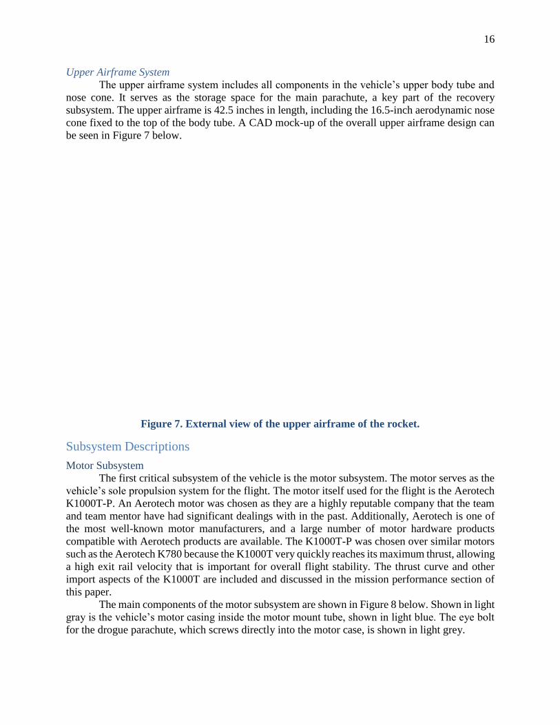
Upper Airframe System
The upper airframe system includes all components in the vehicle’s upper body tube and
nose cone. It serves as the storage space for the main parachute, a key part of the recovery
subsystem. The upper airframe is 42.5 inches in length, including the 16.5-inch aerodynamic nose
cone fixed to the top of the body tube. A CAD mock-up of the overall upper airframe design can
be seen in Figure 7 below.
Figure 7. External view of the upper airframe of the rocket.
Subsystem Descriptions
Motor Subsystem
The first critical subsystem of the vehicle is the motor subsystem. The motor serves as the
vehicle’s sole propulsion system for the flight. The motor itself used for the flight is the Aerotech
K1000T-P. An Aerotech motor was chosen as they are a highly reputable company that the team
and team mentor have had significant dealings with in the past. Additionally, Aerotech is one of
the most well-known motor manufacturers, and a large number of motor hardware products
compatible with Aerotech products are available. The K1000T-P was chosen over similar motors
such as the Aerotech K780 because the K1000T very quickly reaches its maximum thrust, allowing
a high exit rail velocity that is important for overall flight stability. The thrust curve and other
import aspects of the K1000T are included and discussed in the mission performance section of
this paper.
The main components of the motor subsystem are shown in Figure 8 below. Shown in light
gray is the vehicle’s motor casing inside the motor mount tube, shown in light blue. The eye bolt
for the drogue parachute, which screws directly into the motor case, is shown in light grey.

17
Figure 8. Motor system shown inside the lower airframe.
In terms of safety, the motor case is possibly the most important flight component to
consider. The motor case is designed to contain the propellant grains of the Aerotech reloadable
motor. Due to this, the motor casing (an RMS 75/2560) is professionally fabricated from precisely
machined aluminum. This ensures that the propellant can burn in a proper environment without
adversely affecting the remainder of the vehicle. This component also serves as the lower
attachment point for the drogue parachute shock cord.
Housing the motor case and shown below in Figure 9 is the motor mount tube with its three
centering rings. The motor mount tube is a 3.1 inch diameter piece of Blue Tube, allowing for the
installation of the motor case without adapters, and 20 inches in length. This component is
designed to house the motor case separately from the rest of the vehicle. The vehicle’s centering
rings can be seen in brown. These are used to ensure that the motor mount tube, and thus the motor
casing and motor itself, are seated directly and securely in the center of the vehicle. These rings
are composed of high quality plywood and are designed for the specific purpose of centering the
motor. The vehicle contains three centering rings: one at the extreme aft end of the booster tube,
one at the top surface of the fins, and one near the top of the motor mount tube.
Figure 9. Motor mount tube with centering rings attached and the motor case inserted.
18
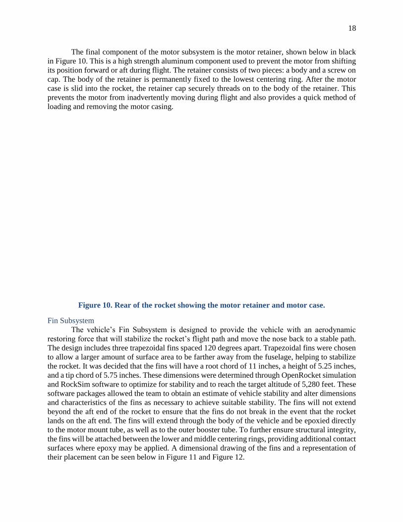
The final component of the motor subsystem is the motor retainer, shown below in black
in Figure 10. This is a high strength aluminum component used to prevent the motor from shifting
its position forward or aft during flight. The retainer consists of two pieces: a body and a screw on
cap. The body of the retainer is permanently fixed to the lowest centering ring. After the motor
case is slid into the rocket, the retainer cap securely threads on to the body of the retainer. This
prevents the motor from inadvertently moving during flight and also provides a quick method of
loading and removing the motor casing.
Figure 10. Rear of the rocket showing the motor retainer and motor case.
Fin Subsystem
The vehicle’s Fin Subsystem is designed to provide the vehicle with an aerodynamic
restoring force that will stabilize the rocket’s flight path and move the nose back to a stable path.
The design includes three trapezoidal fins spaced 120 degrees apart. Trapezoidal fins were chosen
to allow a larger amount of surface area to be farther away from the fuselage, helping to stabilize
the rocket. It was decided that the fins will have a root chord of 11 inches, a height of 5.25 inches,
and a tip chord of 5.75 inches. These dimensions were determined through OpenRocket simulation
and RockSim software to optimize for stability and to reach the target altitude of 5,280 feet. These
software packages allowed the team to obtain an estimate of vehicle stability and alter dimensions
and characteristics of the fins as necessary to achieve suitable stability. The fins will not extend
beyond the aft end of the rocket to ensure that the fins do not break in the event that the rocket
lands on the aft end. The fins will extend through the body of the vehicle and be epoxied directly
to the motor mount tube, as well as to the outer booster tube. To further ensure structural integrity,
the fins will be attached between the lower and middle centering rings, providing additional contact
surfaces where epoxy may be applied. A dimensional drawing of the fins and a representation of
their placement can be seen below in Figure 11 and Figure 12.

19
Figure 11. Dimensioned drawing of the rocket fins.
Figure 12. Rocket cross-section shown from below.

20
Avionics/Payload Bay Subsystem
The avionics and payload bays are located in the vehicle’s center coupler and contain the
components necessary for securing the sample and deploying the vehicle’s parachutes. The main
coupler piece is composed of 15 inches of Blue Tube designed to function as a coupler for 4.014
inch Blue Tube airframes. Taking into account the two airframe bulkheads that extend from the
coupler, the full length of the coupler subsystem is 15.5 inches. The switch band, a 7 inch long
piece of 4.014 inch diameter Blue Tube, can be seen in dark blue wrapped around the coupler.
This piece serves as a backstop for the booster and upper airframe when they are slid onto the
coupler, a mounting point for the rotary switches which arm the vehicle’s avionics, and as a
location for small drilled holes to allow for proper operation of altimeters. The magnetically sealed
hatch door can be seen on the switch band in silver in Figure 13.
Figure 13. Main coupler and payload bay.
As a supplement for the above image, Figure 14 and Figure 15 below show the avionics
and payload bays stripped of the coupler tube and switch band. The brown disks shown are the
coupler and airframe bulkheads, composed of high quality plywood. These provide a physical
barrier between the recovery electronics and the remainder of the vehicle. Shown in dark gray on
the bulkheads are terminal blocks designed to accommodate the E-matches that will ignite the
ejection charges. Wires connect to one side of these blocks from the altimeters, and the E-matches
are attached to the other side. Also mounted on the bulkhead and shown in white are charge cups
designed to hold the recovery system’s ejection charges. These are small PVC cups that will be
filled with black powder. An E-match will then be inserted into the charge cups. The caps are then
covered with foil tape to contain the powder. The final components mounted to the bulkheads are
the eye bolts and quick links, shown in dark gray. The eye bolts run through the bulkheads and are
attached with a nut and washer on each side, as well as a small amount of epoxy. These provide a

21
secure attachment point for the parachute shock cords. The quick links, shown below as gray ovals,
are used to attach the parachute shock cords to the eye bolts. These provide for a strong attachment
point that may be easily assembled before flight and removed afterward.
Looking at the inner components, there are two threaded aluminum rails that span the
length of the coupler. These rods are attached to each bulkhead via a nut and washer on each side.
These both hold the bulkheads on the coupler and provide a rail system for which to slide the
payload and avionics sleds into the coupler. The avionics and payload sleds are shown as light
brown rectangles. These are thin sleds composed of aircraft plywood with small tubes linking the
sled to the threaded rods. These tubes will be 3D printed to the specifications by a team member
using their own 3D printer, which the team used in last year’s competition. These tubes serve as
guides, allowing the sled to smoothly slide on the rails and remain fixed within the system. The
Stratologger altimeter and Telemetrum altimeter can be found on either avionics sled and shown
in light gray are. The altimeters are installed on the opposite side of the hatch door to place them
closer to the outward facing rotary switches that will be used to turn on these altimeters on launch
day. These will be used to record the flight profile and deploy the main and drogue parachutes.
The electrical diagram of the altimeters is shown farther down in Figure 16. Once the vehicle
reaches apogee, the altimeters will trigger the drogue ejection charge to release the drogue
parachute. Later during descent, the altimeters will trigger the main ejection charge to release the
main parachute.
Trimmed bulkheads and a payload containment sled serve as a way to isolate the payload
from the recovery equipment in the unlikely event that the gripper on the hatch door fails and drops
the payload inside the rocket. The bulkheads are trimmed to allow for wires to cross the length of
the coupler from either altimeter to the ejection charges and to allow for the installation of a ~6
inch tracking antenna to the Telemetrum altimeter.
Figure 14. Side view of coupler internals.

22
Figure 15. Placement of altimeters in coupler, with Telemetrum on the left sled and
Stratologger on the right sled.
Figure 16. Electrical schematic of recovery equipment.

23
These trimmed bulkheads will also serve as the mounting point for the internal magnets
and mortice latch that will keep the hatch door in place during the flight of the rocket. When the
hatch door is placed into the rocket, the latches will lock into the strike plate blocks install on either
end of the hatch door. The strike plate blocks are shown below in Figure 17 on a payload equipped
hatch door.
Figure 17. Hatch door with strike plate blocks installed on both ends.
Rail Button Subsystem
The rail button subsystem is responsible for holding the vehicle to the launch rail during
the initial stage of the flight. The rail buttons will be standard 1515 rail buttons designed to work
on a 1.5 inch slotted rail. Each rail button will be attached to a mounting point secured to one of
the vehicles centering rings. This mounting point will consists of a plywood block with a T-nut.
This allows the rail buttons to easily screw in and out in case one needs to be replaced, but it also
provides for a secure mounting configuration. Additionally, this method mitigates any damage to
the structural integrity of the relatively thin centering rings. A close up of one of the rail buttons
can be seen below in yellow in Figure 18. The mounting hardware can be seen below in Figure 19.
Figure 18. Close-up of 1515 rail button.

24
Figure 19. Rail button mounting hardware.
Two rail buttons were chosen for the rocket. Two will be capable of holding the vehicle to
the launch rail. No more than two rail buttons were chosen, as additional buttons increase the drag
on the rail as the vehicle launches and negatively impacts the exit rail velocity. The placement of
both rail buttons can be seen in Figure 20 below.
Figure 20. Placement of rail buttons along the booster tube
Performance Characteristics
Key performance characteristics for the vehicle include apogee, maximum velocity, rail
exit velocity, and stability during flight. The below performance predictions were taken from
OpenRocket, which the team used to model the rocket and simulate its flight. To account for

25
possible mass growth, the simulations also assume that the rocket has a 10% margin on mass, or
about 2 additional pounds.
At present, OpenRocket predicts the vehicle will reach an apogee of 5,370 feet. The team
recognizes that this current simulation shows the vehicle traveling higher that the target apogee of
5,280 feet, but this decision to overshoot a mile was intentional. The subscale test flight results
and previous experience with OpenRocket shows that the software has a tendency to overestimate
apogee and as such the team has opted to overshoot the target altitude in the open rocket software.
In addition to predicted apogee, the vehicle’s maximum velocity also plays a major role in
determining its performance. If during launch the rocket reaches the transonic region, Mach 0.8 to
1.2, there is the potential for a negative impact on performance due to the generation of
compression waves. Structural damage could occur as well, so the team was careful to ensure the
rocket does not approach supersonic speeds. With the current design, OpenRocket predicts a
maximum velocity of 711 ft/s, or Mach 0.64. This velocity is well below the lower limit of the
transonic range, so the team is confident it will not impede performance.
Additionally, for any flight to be successful, it is crucial that the rocket achieve a sufficient
velocity as it leaves the launch rail. The recommended minimum rail exit velocity is 45 ft/s, a
velocity that is considered high enough to ensure aerodynamic stability once the vehicle is no
longer guided by the launch rail. In OpenRocket, the flight simulation predicts a launch rail exit
velocity of 73.3 ft/s. This velocity is significantly above the recommended minimum, so the
vehicle should not encounter stability issues once it leaves the rail.
Finally, once the vehicle leaves the rail and continues accelerating, it needs to have a high
enough stability margin to ensure it continues traveling vertically throughout its flight. A minimum
stability margin of 2 calibers is considered sufficient to ensure control is maintained during launch.
A rocket with a stability margin over 2.5 calibers, however, can be considered overly stable. With
these considerations in mind, the team optimized the vehicle design to ensure its stability margin
fell between 2 and 2.5 calibers. OpenRocket calculates that the current design has a stability margin
of 2.39 calibers, within the recommended range.
Since PDR, additional modeling and analysis has been completed to represent the vehicle
as accurately as possible in several software environments. Notably, the Open Rocket model of
the vehicle was vastly refined to increase the correlation between the model and the vehicle design.
Component mass estimates and locations within the vehicle were made as accurate as possible.
When available, past data or actual measurements were used for the mass of individual parts.
Otherwise, the masses were retrieved from the suppliers’ specifications. Every single component
was placed in the model to correctly reflect the position in the final vehicle design. This allows for
not only a model of the full vehicle mass, but also of the center of gravity and stability margin.
These characteristics, as well as a mass statement, are given in the Mission Performance
Predictions and Integrity of Design portions of this report, respectively. Additionally, a custom
simulator was coded in Matlab and the software package RockSim was used to further analyze the
performance of the vehicle.
The above serves as a quick overview of the rocket from Openrocket. Performance analysis
of the rocket from the custom simulation code and RockSim will be discussed in the mission
performance prediction section of the report.
Vehicle and Recovery Requirements Table 3 given below lists all project requirements placed on the vehicle, as well as the
design features that satisfy these requirements and the methods of verification.

26
Table 3. Vehicle Requirements and Verification
Requirement Design Feature Verification Method
Deliver payload to altitude of
5,280 feet above ground level.
The combination of the
Aerotech K1000T-P motor
and vehicle geometry will
allow the rocket to reach this
target altitude.
Modeling, simulation, and
test flight. Barometric
altimeter will be used to
record official altitude.
Designed to be recoverable
and reusable.
All materials used in
construction have been
evaluated for durability. The
rocket will utilize a dual
deployment recovery system
to ensure that each section of
the rocket lands with less than
75 ft-lbf of kinetic energy.
Hand calculation of the
kinetic energy of each rocket
section upon landing;
adequate construction
techniques; visual inspection
for any flaws in vehicle and
components.
Have a maximum of 4
independent sections.
During apogee and descent,
the rocket has been designed
to break apart into 3
independent sections: booster,
coupler and upper airframe.
Modeling and visual
inspection.
Rocket limited to a single
stage.
The rocket will only carry one
single-stage motor, the
Aerotech K1000T-P.
Modeling and selection of
correct motor.
Capable of being prepared for
flight within 2 hours.
Vehicle components such as
the motor retention system
and payload sleds have been
chosen to allow for quick
assembly.
Assembly testing and practice
prior to launch events.
Capable of remaining in
launch ready position for 1
hour.
All power supplies are
designed to function for well
in excess of this time limit.
Testing all electronic
components to ensure they
have sufficient power
lifetimes.
Capable of being launched by
a 12 volt direct current firing
system.
The vehicle employs a
standard motor igniter
compatible with the standard
12 volt system.
Design and inspection.

27
Requirement Design Feature Verification Method
Use a solid motor propulsion
system using APCP that is
approved and certified.
An Aerotech K1000T-P
reloadable rocket motor will
be used and has been certified
by the TRA.
Design and inspection.
Total impulse provided by the
launch vehicle should not
exceed 5,120 Newton-
seconds.
The total impulse of the
Aerotech K1000T-P is 2511.5
Ns.
Design and inspection.
Team must provide and inert
of replicated version of the
motor, with matching weight
and size.
A hollow motor shell will be
produced and filled with
ballast to match the weight of
the functional motor.
Design and inspection
Burst/Ultimate pressure Vs.
Max Expected Operating
Pressure shall be 4:1, with
supporting design
documentation.
The vehicle does not contain
any pressure vessels.
Design and inspection.
Pressure vessels must contain
solenoid pressure relief valves
that sees complete pressure of
tank.
The vehicle does not contain
any pressure vessels.
Design and inspection.
Complete pedigree of tank
must be provided, its history,
number of pressure cycles put
on the tank, by whom and
when.
The vehicle does not contain
any pressure vessels.
Design and inspection.
Launch and recover a
subscale model of the full-
scale rocket prior to CDR that
should perform similarly to
the full-scale model.
A subscale rocket was
construction and launched
this last December. The
rocket was about a 1:2 scale
model of the full scale and
closely matched the
aerodynamics of the full scale
design at the time.
Subscale was successfully
launched and recovered on
December 19, 2015. Shares a
similar stability margin to the
full scale design and is about
a 1:2 scale model of the full-
scale.

28
Requirement Design Feature Verification Method
Prior to FRR, the full-scale
rocket shall be launched and
recovered, in order to ensure
that the vehicle and recovery
system function properly, in
fully ballasted configuration,
with no additional
modifications being made
after successful completion of
test flight.
The team plans to construct
and launch the fully
assembled final rocket prior
to FRR.
To be confirmed through full
scale flight test and
construction.
Maximum budget of $7,500 The current budget of the
final system is $3851.30 and
future spending will be
tracked to ensure the limit is
not exceeded.
Budget planning and
inspection.
Deploy drogue chute at
apogee.
The primary altimeter will
detect when the rocket has
reached apogee. It will then
trigger an E-match to ignite
the black powder charge on
the lower bulkhead of the
coupler, separating the
booster and coupler and
releasing the drogue
parachute.
Modeling and testing of
parachute deployment
systems.
Deploy main chute at a lower
altitude.
The primary altimeter will
detect when the rocket has
descended to 450 feet. It will
then trigger an E-match to
ignite the black powder
charge on the upper bulkhead
of the coupler, separating the
coupler and upper airframe
tube and releasing the main
parachute.
Modeling and testing of
parachute deployment
systems.

29
Requirement Design Feature Verification Method
Each independent section of
the launch vehicle shall have
a maximum kinetic energy of
75 ft- lbf.
The main and drogue
parachutes were chosen to
provide enough drag to slow
each rocket section to a
terminal velocity that allowed
for an acceptable maximum
kinetic energy. See Kinetic
Energy calculations in
Mission Performance Criteria
section.
Hand calculations of the
kinetic energy of each rocket
section upon landing. To be
confirmed based on empirical
test data.
Electrical circuits of the
recovery system shall be
completely independent of
electrical circuits of the
payload.
The only function of the
recovery electronics are to
record the flight profile and
ignite ejection charges.
Design and inspection.
The recovery system must
contain redundant,
commercially available
altimeters.
Each ejection event is
controlled by fully redundant
and independent avionics
components.
Design and inspection.
Dedicated arming switches
shall arm each altimeter from
the exterior of the rocket.
Both altimeters have a
dedicated rotary switch on the
exterior of the rocket.
Design and inspection.
Altimeters must have
dedicated power supplies.
Each altimeter has its own
battery power supply.
Design and inspection.
Arming switches must be
capable of being locked in the
ON position.
The rotary switches chosen
are capable of being locked in
the ON position.
Design and inspection.
Removable shear pins shall be
used for both the main
parachute and drogue
parachute compartments.
Shear pins connect the
booster and coupler, which
separate to deploy the drogue
parachute. Shear pins also
connect the coupler and upper
airframe tube, which separate
to deploy the main parachute.
A final set of shear pins
connects the upper airframe to
the nose cone.
Design and inspection.

30
Requirement Design Feature Verification Method
Electronic tracking devices
shall be installed in the launch
vehicle.
The vehicle will utilize the
GPS capabilities of the
Telemetrum altimeter, as well
as a radio frequency tracking
device.
Design and inspection.
Any untethered section or
payload component shall have
its own electronic tracking
devices.
There are no untethered
sections.
Design and inspection.
Recovery systems electronics
cannot interfere with any
other on- board electronic
devices during flight.
No onboard components are
expected to interfere with the
recovery electronics or vice-
versa.
Interference and functional
testing of recovery
components upon
construction of coupler.
Recovery system altimeters
must be physically located in
a separate compartment from
other radio frequency
transmitting and/or magnetic
wave producing devices.
Altimeters are installed into
their own bays, safe from any
interference from the magnets
in the payload bay.
Design and inspection.
Recovery system electronics
shall be shielded from
onboard transmitting devices.
The recovery electronics are
located in a physically
separate compartment from
the radio frequency
transmitter.
Design and inspection.
Recovery system electronics
shall be shielded from devices
that may generate magnetic
waves.
The recovery system
electronics shall be shielded
from the crane’s
electromagnet.
Design and inspection.
Recovery system electronics
shall be shielded from any
other devices that may
interfere with proper
operation of recovery system
electronics.
No onboard components are
expected to interfere with
recovery electronics. The
electronics are physically
isolated and shielded
regardless.
Testing to ensure recovery
systems will function when
all electronics are running.
Approach to Workmanship
As a responsible team, safety as well as the quality of the final product are held in the
highest importance. A detailed agenda and construction procedures has been created to provide
every member with vital knowledge of proper and safe construction techniques. In addition the
team can consult experienced members and the team mentor for further clarification of proper

31
technique. As well as benefiting safety considerations, these moves create a redundancy in
knowledge that will allow the Illinois Space Society to continue construction uninterrupted and on
schedule in the event that certain personnel are unable to attend a build session. All construction
will be overseen by the safety officer and one veteran member of the group that can provide hands-
on instruction to help both ensure the safety of every participating member and that the work is
being done correctly for a quality build. The aforementioned team mentor will be involved with
the team for every test and will consistently check in on the team during construction to ensure all
proper precautions are being met. The combination of these efforts will allow the team to create a
quality project without endangering any individual on the team. Should any danger arise every
member has been instructed to err on the side of caution and the safety of themselves and of the
team, regardless of any potential impact on the quality of the project itself. In general, ISS strives
to apply proper workmanship both to enhance the probability of mission success, and to mitigate
any safety risks.
Test Descriptions and Results
As construction has not been completed, the only physical test conducted to this point is
the Subscale Flight Test, which is discussed at length in the Subscale Flight Results section of this
report. This test consisted of flying an aerodynamically similar 1:2 scale model of the full scale
vehicle. The model was flown two times at a local launch with the team mentor present. The flight
proved that the aerodynamics of the vehicle allow for a safe flight.
Many other tests are planned upon completion of vehicle component construction and
integration. Due to the destructive nature of most structural testing, many of the tests completed
on the constructed vehicle will be inspection based. Due to budgetary and scheduling constraints,
the team will not be able to empirically verify the failure strengths of significant airframe
components. However, all flight critical hardware is commercially available and either specifically
designed for high power rockets, or rated for much higher loads than will be experienced in flight.
Individual components will be inspected and manually loaded on a case by case basis as
construction is completed. Team members and the team mentor will inspect all connections and
other construction features. They will ensure that the manufacturing process was completed
correctly and produced components of sufficient structural integrity. Additionally, each time a
component is completed, its integration with other completed parts will be tested. This includes
interfaces such as the coupler to airframe connections and other sizing constraints such as
parachute bay lengths. Inspecting components as they are completed will allow the team to notice
any errors or defects as early as possible, and rectify these errors without delay.
It is also important to test functionality when applicable. Electronic components will all be
tested individually before construction to eliminate premature electronic failures. Proper wire
connections will be verified and all electronics will be inspected for exposed wires.
The parachutes will be inspected for any holes, rips or tears. When the parachute is packed
on launch day, a pull test will be performed to assure there is not too much resistance. Packing will
be adjusted accordingly and baby powder will be applied to the inner fuselage wall to reduce
friction and ensure parachute ejection.
One critical system of the vehicle, the hatch system, will be fully tested on the ground upon
completion of its construction. As the operating conditions of the hatch are well defined, the hatch
testing will be relatively simple. The mechanism must only complete the task of closing the hatch
door when in a horizontal, stationary position. Therefore the system can be tested by simply
placing the door repeatedly and confirming the installation is smooth and absent of any notable

32
errors and that a person can remove the hatch door by disengaging the mortice latches following
installation.
The integration with the AGSE systems may also be tested on the ground. This includes
loading the vehicle on the rail, installation the hatch door that contains the payload, erecting the
launch pad and inserting the motor igniter. As these are the most complicated systems that the
team has the least amount of experience with, it is highly important that these systems be verified
through significant ground testing. Similar to the hatch mechanism, the loadings and physical
requirements of these tests are also relatively fixed and well known. Therefore the testing will
again essentially consist of running the system many times in succession to prove that the
components have been properly constructed and integrated. This will first be done without the
vehicle itself, to confirm the logic and timing of the system. Subsequently, the vehicle will be
placed on the rail in order to confirm the precision of the AGSE system and its ability to handle
the weight of the vehicle.
The Illinois Space Society has experienced problems in the past with electronic hardware
timing out or shutting down on the launch pad before flight. Through past experience and testing,
it is known that the vehicle’s altimeters will remain active during pre-flight activities, assuming
sufficient battery power. However other electronics such as the AGSE controller must be tested as
well. A simple test may be used to confirm the usability of the electronic hardware. The
components will be powered on and be capable to sit idle for three hours. This allows enough time
for the two hour assembly window and the required on-pad standby capability of one hour.
Nominally the components will remain active indefinitely as long as power remains, which is the
expected result.
In order to meet the two hour assembly requirement, the team will also test the capabilities
of launch personnel by completing assembly tests. Upon completion of construction, the team will
repeatedly assemble and disassemble the vehicle in order to confirm this process may be completed
within two hours. Most importantly, the team has found in the past that parachute packing is often
much more complicated than expected. Although the compact parachutes used on the vehicle will
mitigate this issue, it is still important to determine a proper packing procedure.
The team will also test the ejection procedures of the vehicle. This is discussed further in
the Recovery System Testing portion of this report. This test will allow the team to determine the
correct size and number of shear pins to place at all separating interfaces, as well as the charge size
required to break these shear pins and eject the parachute. These tests will also confirm that the
parachute packing method allows the recovery devices to be reliably ejected from the vehicle.
The team will be able to simulate the loadings on the vehicle components expected during
flight, however the full scale test flight will provide the true empirical evidence that the vehicle is
completely structurally sufficient. The full scale test flight is by far the most important test
undertaken during the project, as it will prove that all vehicle components and subsystems are able
to function when fully integrated.
During the full scale flight, the team will aim to proceed exactly as it will on launch day.
Although not required, the team intends to fully utilize the AGSE system during the full scale
launch. The team will assemble and prepare the vehicle and AGSE system for launch within two
hours. The sample will be placed at the desired position near the rocket, and team members will
proceed to a safe distance. The AGSE system will then be initiated, and pre-launch procedures will
proceed culminating in the launch of the vehicle. Upon recovery of the vehicle the team will
inspect the components for any damage and analyze the onboard altimeter data. A brief summary
of the planned testing is given in the Table 4 below.

33
Table 4. Vehicle Testing Summary
Test to be Completed Test Description Desired Result
Subscale Flight Test Fly an aerodynamically
identical, scaled down version
of the full scale design.
Stable flight providing data to
improve accuracy of
predictions (Complete).
Component Inspection Manually stress completed
components to check for
defects or weak connections.
Defects are either not present
or rectified, connects are
determined to be sufficient.
Integration Inspection Connect all components
which share interfaces on the
vehicle.
Components are found to
smoothly integrate without
interference or undesired
friction.
Hatch Door Installation Repeatedly install hatch door
and remove it by disengaging
the mortice latches.
The hatch door is easily
installed and can be removed
when needed.
Time-Out Testing Critical electronic
components are powered on
and left to sit idle.
All components remain active
for at least three hours.
AGSE Integration The AGSE system is actuated
with the fully loaded rocket
integrated on the launch rail.
The AGSE system properly
actuates, loading, lifting and
preparing the rocket for
launch at least 20 times in
succession.
Assembly Testing All team members attending
the launch will fully assemble
the vehicle and all AGSE
equipment.
The team is able to assemble
all equipment within two
hours a minimum of three
times.
Ejection Testing Manually ignite ejection
charges in the completed
vehicle on the ground.
Determine the appropriate
number of shear pins and
ejection charge sizes, confirm
parachutes are reliably
ejected.
Full Scale Flight Test The vehicle will be flown in
its full competition launch
configuration.
The vehicle meets all mission
requirements while executing
a nominally safe flight.

34
Planning of Manufacturing, Verification, Integration and Operations
The manufacturing and assembly of the flight vehicle will be broken down into several
individual sections and will take place periodically throughout the spring semester. All major parts
have been ordered over the University of Illinois’ winter break. Building will begin once all parts
to a given section have arrived. Members of the team building the flight vehicle will rotate in turns
to ensure that only a small group of students are constructing at any given time. This reduces safety
hazards, confusion, and distractions. It also ensures that all students present at a given meeting will
have a specific assigned task to complete. Work instructions will be created for each subsection of
the rocket before construction begins. These work instructions will be reviewed by team members
before each build session. Status reports will also be written after build sessions to eliminate any
progress confusion for following build meetings.
Safety has been the primary factor while determining construction techniques. This refers
to the safety of team members during construction, as well as constructing a vehicle which will
execute the mission safely. Safety equipment such as gloves, safety glasses, and earplugs will be
worn when necessary throughout the build process. In particular, gloves will be used while
handling epoxy and respirators will be worn while grinding any major parts or sanding the
fiberglass fins.
The projected construction techniques are subject to change as the team approaches
obstacles in the manufacturing process much like what was done while building the subscale
model. The same tools used to build the subscale model will be used to build the full scale. This
includes an assortment of tools from basic office supplies to power tools. Basic supplies include:
sharpies, masking tape, mixing sticks, sandpaper of assorted grit, a tape measure, a level, an X-
Acto knife, a C-clamp, and rubbing alcohol. Power tools include: a drill and bits, a Dremel tool, a
soldering iron and a palm sander. Epoxy will be used for bonding major areas of the flight vehicle.
The amount applied will be determined by the structural integrity and consequential drag effects
while in flight. Since there are many hazards associated with exposure to epoxy fumes, great
caution will be used when handling this resin system.
Before construction, all parts and hardware will be inventoried, inspected, weighed,
cleaned and labeled. All parts will be inspected for cracks or deformities and checked for proper
fitting. The vehicle will be assembled as fully as possible without permanently attaching any
components to ensure all components were manufactured to correct dimensions. General
construction practices will include marking all hole locations, confirming all hole and insert sizes,
and double checking locations before drilling. Surfaces that will have epoxy applied will be sanded
with 60 grit or coarser sandpaper and will be later cleaned with rubbing alcohol.
Construction will start with the motor mount. While assembling the motor mount tube and
centering rings, several things will be accounted for. Three center rings will be used for additional
support and ease of alignment. The location of the center rings will be marked on the motor mount
and body tube in three different locations: the top ring slightly below the motor mount tube, the
middle ring to be aligned with the top of the fins, and the bottom ring to align the retainer with the
bottom of the rocket. Motor retention will be ensured by an Aeropack 98mm Motor Retainer
constrained at the extreme aft end of the rocket. The centering rings are commercially available,
pre-cut to size, and constructed of aircraft grade plywood.
Rail button positions will be marked on the airframe. The rail buttons will be attached
before the motor mount is fixed inside of the rocket. T-nut interfaces will be created on the inside
of the rocket. These T-nut interfaces will consist of a T-nut inserted into a block of plywood. These
interfaces will be mounted to the top and bottom centering rings. The motor mount will be inserted

35
into its marked location in the booster airframe at a later time. The inside of the booster airframe
and the fin slots will be sanded. Epoxy will be applied to the top of the center rings. For the bottom
center rings, epoxy will be applied through a hole for the top ring and through a fin slot for the
middle ring.
The avionics bay will be assembled through many subparts. At the start, the hatch door
will be cut from the switch band and the corresponding but slightly smaller hole will be carefully
cut from the coupler tube. All electronics will be carefully soldered to assigned locations and
appropriate electrical hardware will be used to assure that no wires are left exposed. The bulkheads
will have threaded rod rails running the length of the avionics bay to act as guide rails for the
avionics sleds and to hold the bulkheads in place. Eyebolts for parachutes, charge cups and
terminal blocks will all be added to the bulkheads of the avionics bay. The switch band will be and
attached next.
The fins will be laser cut out of fiberglass. The flight vehicle will be constructed with
through-the-wall fins. These must be able to fit between the middle and bottom center rings. A fair
amount of epoxy will be applied between the fins and the body tube for support. Internal fillets for
the fins will be used since the fins must fit tight to the motor mount tube and the center rings must
fit snug to the top and bottom of the fins. Fin alignment will be insured through the use of a simple
jig consisting of slots placed 120 degrees apart in a cardboard sheet. This alignment guide will be
laser cut to ensure accuracy and precise alignment.
The hatch door mechanism will be constructed with the same techniques of measuring and
marking all parts as described above to ensure proper fitting. More careful and precise
measurements will be made since this system is relatively small and requires higher accuracy. The
bulkheads that define the space set for payload containment will be trimmed to allow for altimeters
wires to pass below the payload bay. Then, the mortice latches and internal magnets that will keep
the hatch door attached to the vehicle during flight will be mounted onto these trimmed bulkheads.
The hatch door will be constructed simultaneously and the wooden blocks that will serve as strike
plates for the latches will be carefully measured cut at the time to allow for proper integration of
the hatch door and a flush fit into the vehicle. Construction of the electromagnet that will move
the payload and integration with the AGSE crane will be discussed in the AGSE section of this
report.
Finishing the build process will include priming and painting with the possible application
of decals. Pressure relief holes in the airframe sections will determined and drilled to allow
pressure to equalize in flight. Verification of the vehicle construction will be completed on
individual components on a case by case basis. As components are completed, experienced team
members and the team mentor will inspect all connections and other construction features to ensure
the manufacturing process proceeded as planned and provided for sufficient structural integrity.
Additionally, each time a component is completed, its integration with other completed parts will
be tested. This includes interfaces such as the coupler to airframe connections and other sizing
constraints such as parachute bay lengths. Inspecting components as they are completed will allow
the team to catch any errors or defects as early as possible, and rectify these errors without delay.
Integrity of Design
Fin Suitability
The rocket was designed by selecting individual pieces of the craft at various respected
rocketry retailers. Combinations of nose cones and body tubes were recommended by respected
hobbyist shops and the standardization in their construction adds confidence to the system.
Additionally, although this rocket is not a kit the design is standard enough to allow for confidence

36
in the team’s predictions and simulations of its launch. Although the fins are custom made and
designed, the design was heavily influenced by investigating similar proven rockets of this class
and are of a fairly standard shape. The fins do not sweep back beyond the aft end of the body tube,
an issue which commonly results in broken fins upon landing. Most importantly, the fins serve to
locate the center of pressure around 2.4 calibers aft of the center of mass, providing sufficient and
vital stability. The scaled down version of this fin style and shape proved successful with the
launch of the subscale vehicle in providing stability to the system by counteracting deviations to a
typical flight path. As such the team believes the current fin style and size are suitable for use in
providing similar stability to the full scale rocket.
Proper Use of Structural Materials
Materials were chosen for their ability to withstand the strength requirements of the mission
and balanced with both cost and weight. As covered in previous documentation, a trade study was
performed to logically determine the best materials for the rocket when taking into account the
aforementioned qualities of each material. The fins are composed of fiberglass, a tried and tested
material in the high powered rocketry community. This ensures that the fins will be able to not
only survive the aerodynamic load placed on them, but also successfully lend needed stability to
the rocket throughout the course of its flight. Complications such as oscillations of the fins on the
body are minimized with proper application of epoxy during installation and the inherent stiffness
of the fiberglass.
The body tube is composed entirely of Blue Tube. Among the hobbyist community, Blue
Tube has risen in popularity as a viable replacement for materials traditionally used in this rocket
class, such as fiberglass. Although not quite as strong as fiberglass, Blue Tube is rated more than
high enough to withstand the loads it will encounter on the mission. Added benefits include being
nearly half as light and a third as expensive as a fiberglass solution. Along with these benefits, this
solution is shatterproof, greatly aiding the reusability of the rocket as stated previously as a mission
goal.
The bulkheads will be composed of aircraft plywood and are purchased precut from a
respected shop. With proper installation, the bulkheads will be more than adequate for supporting
the stress it will undergo throughout the flight as previous application has shown. Aircraft grade
plywood has been used numerous times as a bulkhead material on previous ISS rockets. All
attachment hardware is composed of high strength metal, steel in particular. Forged steel eye bolts
are used to securely attach the parachutes and withstand the load of deployment without failing.
Furthermore, the parachute harnesses themselves attach using steel quick links. Steel quick links
have been used in the past by veterans of the group and are an industry standard.
The hatch assembly will be securely placed via two flanking mortice latches and magnets
to prevent movement during flight as well as ensure a flush finish along the side of the rocket. The
3D printed gripped that will hold the payload itself was strong enough to hold the identical payload
in last year’s competition. In the unlikely event that the payload comes loose during flight, the
payload will be contained within a chamber isolated from important recovery equipment.
Proper Assembly Procedures
As discussed in detail previously, the team will follow a detailed agenda and explicit
building instructions in the day to day work of building the craft. Any unforeseen interruptions to
the workflow will be overseen by veteran members and the team mentor to minimize loss of time
and ensure necessary timelines are still met.
All permanent attachments will be accomplished using a high strength epoxy that members
of the group are familiar with and is suitable for the mission. All surfaces to be epoxied will be

37
sufficiently roughened with coarse sandpaper in order to create a proper surface for the epoxy to
bond to. After sanding, all surfaces will be properly cleaned to remove any dust or particles that
would interfere with the bonding of the epoxy. For fins and centering rings, epoxy fillets will be
applied to each surface of every interface. Prior to construction, team members will inspect and
test all parts to ensure that they are capable of attaching to the required location. After each
construction step, additional fit tests will be conducted to ensure that all components are still able
to make the required interfaces. During construction, levels and straight edges will be utilized to
confirm that all parts, especially fins, are properly aligned and attached to the vehicle. Proper sizing
of epoxy fillets and bonds will be determined utilizing the knowledge of veteran members and the
team mentor
Motor Mounting and Retention
The team has completed much research to come to a sufficiently strong motor mounting
and retention assembly. The motor mount will undergo extreme levels of load while the motor
itself is firing, and as such proper installation of the motor assembly is mandatory.
To this end, centering rings composed of high quality and strong aircraft grade plywood
designed for the specific purpose of centering the motor will be employed. The vehicle contains
three centering rings. One at the extreme aft end of the booster tube, one at the top surface of the
fins, and one at the top of the motor mount tube. The centering rings will be strongly bonded not
only to the outside of the motor tube but to the inside of the body tube. Syringes will be used to
eject epoxy on the inner airframe to further ensure the proper and stiff installation of the centering
rings. Furthermore, the installation of the fins will prove beneficial to the overall integrity of the
assembly. The fins will be installed in-between the bottom two centering rings. Fillets will also be
employed in fin installation and its attachment to the motor mount tube will aide in the overall
integrity and stiffness of the motor assembly.
The motor mount tube itself is composed of strong and stiff Blue Tube. This component is
designed to house the motor case separately from the rest of the vehicle. This system provides a
secure and stable installation of the motor casing.
Finally, the motor retainer is a high strength aluminum component consisting of two pieces:
a body and a screw on cap. The body of the retainer is permanently affixed to the lowest centering
ring. Twelve screws will be slotted through the retainer body and lowest centering ring. The
connecting surface will also be epoxied for additional integrity. After the motor case is slid into
the rocket, the retainer cap simply but securely threads on to the body of the retainer. This prevents
the motor from inadvertently moving during flight.
Status of Verification
Vehicle verification is to be decided since construction itself is still in its earliest stages
due to the winter break. That being said, verification tests are also being planned at this time. Each
component and subsystem, such as the hatch, will be individually tested as they are built and before
being placed inside of the body of the rocket. Additionally, the planned later full scale test flight
will test the vehicle as a whole, at which point concrete verification can be obtained. Until then,
all simulations and calculations lend credibility to the design and specifications of the rocket
Dimensional Drawings
Full CAD models of the vehicle and subsystems were given above in their respective
subsections. Dimensioned drawings of significant portions of the vehicle are given below.
A dimensioned drawing of the entire vehicle is given below in Figure 21, with all
dimensions given in inches. The first image is a drawing of the vehicle as a whole. Critical vehicle

38
dimensions are given, such as the length of the body components and parachute compartments.
The lengths of the drogue and main parachute compartments are 11 and 14.75 inches, respectively.
The nose cone is 19.75 inches long (16.5 inches exposed), the upper airframe is 26 inches long,
the coupler is 15.5 inches long (7 inches exposed), and the booster is 40.75 inches long (including
the motor retainer). All outer diameters of airframe tubing components are 4.014 inches. The
vehicle has a total length of 90.25 inches, or 7.52 feet.
Figure 21. Dimensioned drawing of the full rocket.
Figure 22, Figure 23, and Figure 24 below give more detailed dimensions of the avionics
and payload bay, with all dimensions given in inches. Of note are the overall length of the coupler,
15.5 inches, and the switch band length of 7 inches. The payload bay is found in the center of this
switch band, with sufficient room for the 4.75 inch payload length. The majority of the additional
components are determined by the sizes of purchased components and are not variable in terms of
vehicle design.
Figure 22. Dimensioned drawing of the coupler with quick links attached.

39
Figure 23. Dimensioned drawings of the coupler interior.
Figure 24. Vertical cross section of the coupler with dimensions of attached components.
Figure 25 below shows the geometry of the designed custom fins. It was decided that the
fins will have a root chord of 5.5 inches, a height of 4.25 inches, and a tip chord of 0.5 inches. The
Fins will have a thickness of 0.25 inches.

40
Figure 25. Drawing showing the major dimensions of the fins.
Figure 26 and Figure 27 below gives the dimensions of the RMS 75/2560 motor case that
will house the motor through all stages of flight. Dimensions are taken from a front view and side
view, as marked.
Figure 26. Motor case dimensioned drawing front.

41
Figure 27. Motor Case Dimensioned Drawing - Side.
Mass Statement
Table 5 below lists masses for all components in the current design of the rocket. Components
are organized by subsystem, and component materials are listed when applicable. For
components that have multiple units on the rocket, such as the fins (3) or eyebolts (2), the masses
given are for the combined net mass of these components, not a single unit.
The team believes the current mass statement is relatively accurate at this stage of
development. The vast majority of masses have been retrieved from manufacturer specifications
or data ISS has collected throughout previous projects. An epoxy mass of 2 pounds has been
estimated to account for the weight due to construction and falls in line with accurate estimations
taken in prior years.
Although the team believes the statement accurately reflects the current design mass of the
vehicle, it is understood through experience that the mass of the vehicle will almost certainly
change by the time the final design is determined. Given this reality, the team has allowed for the
final launch mass to be 22.51 lbs. This final estimated mass includes 2 lbs of reserve mass, or
around a 10% margin. Experiences in past years with mass growth helped in determining an
appropriate amount of mass to reserve for future growth. The team does not anticipate a mass
growth quite this large, but this will allow for flexibility in attempts to reach the target altitude.
The current motor and parachute choices have been designed to optimally meet contest
requirements even with a 22.51 lb rocket.

42
Table 5. Breakdown of Components in Structures and Recovery by Mass
Subsystem Component (Quantity) Material Weight (lbs)
Booster Trapezoidal Fin (3) Fiberglass 2.46
Body Tube Blue Tube 2.0 1.59
Centering Ring (3) Plywood 0.06
Motor Mount Tube Blue Tube 2.0 0.45
Motor Retainer Assembly Aluminum 0.19
Fruity Chutes 15” Drogue Nylon 0.09
Drogue Shock Cord ½” Tubular Kevlar 0.80
Rail Button (2) Delrin-Plastic 0.03
K1000T Motor Assembly* Various 5.67
70% Total Estimated Epoxy Epoxy 1.40
70% of 2lb Margin N/A 1.40
Booster Total 14.14
Coupler Body Tube Blue Tube 2.0 0.42
Switch band Blue Tube 2.0 0.23
Coupler Bulkhead (4) Plywood 0.46
Tube Bulkhead (2) Plywood 0.24
Eyebolt (2) Forged Steel 0.40
Eyebolt Nut (2) Aluminum 0.10
Eyebolt Washer (2) Aluminum 0.02
Stratologger Onboard Altimeter 0.03
Telemetrum Onboard Altimeter 0.03
9V Battery Duracell 0.11
Telemetrum Battery LiPo 0.20

43
Subsystem Component (Quantity) Material Weight (lbs)
Battery Clip Plastic 0.05
Threaded Rod (2) Aluminum 0.28
Payload PVC Pipe w/ Sand 0.25
Rotary Switch (2) Plastic 0.03
Charge Cup (4) PVC 0.02
Avionic Sled (2) Plywood 0.20
Coupler Magnet (4) Iron Alloy 0.40
Shear Pin (6) Nylon 0.02
Union 2648 Tubular Latch Zinc Finish 0.44
Strike Plate/Wooden Block Plywood 0.10
20% Total Estimated Epoxy Epoxy 0.40
20% of 2lb Margin N/A 0.40
Coupler Total 4.83
Upper
Airframe
4.00” X 16.5 Nosecone Polypropylene Plastic 0.64
Body Tube Blue Tube 2.0 0.86
Iris Ultra 72” Parachute Nylon 0.84
Shock Cord ½” Tubular Kevlar 0.80
10% Total Estimated Epoxy Epoxy 0.20
10% of 2lb Margin N/A 0.20
Upper Airframe Total 3.54
TOTAL
MASS
22.51
*K1000T Motor Assembly Weight is broken down as follows.

44
Table 6. Breakdown of K1000T Motor Assembly by Mass
Component Mass (lbs)
Propellant 2.60
RMS-75/2560 Aluminum Motor Case 1.23
Misc. Material 1.84
K1000T Motor Assembly 5.67
With the current design, the team expects the rocket to have a total mass of 22.51 pounds.
Once components are purchased and received, their actual masses will be determined and using to
zero in on a more exact total mass that takes into account possible deviations from manufacture
provided masses. As noted this mass statement include 2 additional pounds of unspecified mass
distributed throughout the rocket. These 2 pounds represent about a 10% margin on the actual total
mass, which should account for any mass growth that occurs during further design and
construction.
Safety and Failure Analysis
Table 7 discusses the risks associated with constructing and operating the vehicle as a
completed unit. Further safety and failure analysis is discussed in the safety and recovery sections
of this report.
Table 7. Risk Analysis of Vehicle
Risk Probability Impact Solution
Working with
Hazardous
materials
Low to
moderate
Bodily injuries
such as scars,
burns, and rashes
caused by failure
to comply with
safety procedures.
The safety officer will inform all of the
members working in the lab on the safety
procedures and explain the risks that
come along with working with hazardous
materials. The safety officer will
supervise when any of these materials are
in use and ensure that Material Safety
Data Sheets and protective equipment be
readily available to all of the members.
Working with
tools and
machinery
Low to
Moderate
Physical bodily
damage that could
possibly be
permanent.
Each member is required to take a
general lab safety course and will be
trained to use new forms of tools and
machinery by the safety officer or by
experienced members.
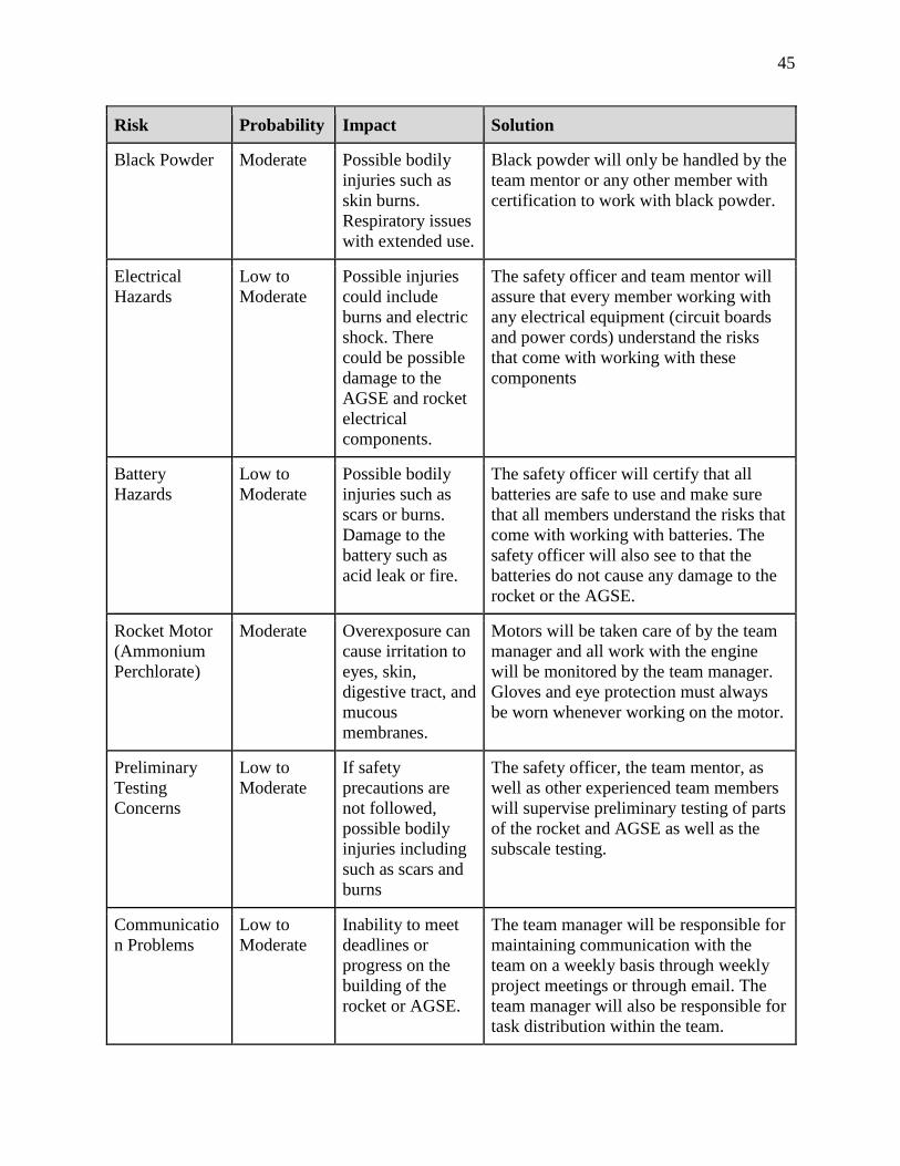
45
Risk Probability Impact Solution
Black Powder Moderate Possible bodily
injuries such as
skin burns.
Respiratory issues
with extended use.
Black powder will only be handled by the
team mentor or any other member with
certification to work with black powder.
Electrical
Hazards
Low to
Moderate
Possible injuries
could include
burns and electric
shock. There
could be possible
damage to the
AGSE and rocket
electrical
components.
The safety officer and team mentor will
assure that every member working with
any electrical equipment (circuit boards
and power cords) understand the risks
that come with working with these
components
Battery
Hazards
Low to
Moderate
Possible bodily
injuries such as
scars or burns.
Damage to the
battery such as
acid leak or fire.
The safety officer will certify that all
batteries are safe to use and make sure
that all members understand the risks that
come with working with batteries. The
safety officer will also see to that the
batteries do not cause any damage to the
rocket or the AGSE.
Rocket Motor
(Ammonium
Perchlorate)
Moderate Overexposure can
cause irritation to
eyes, skin,
digestive tract, and
mucous
membranes.
Motors will be taken care of by the team
manager and all work with the engine
will be monitored by the team manager.
Gloves and eye protection must always
be worn whenever working on the motor.
Preliminary
Testing
Concerns
Low to
Moderate
If safety
precautions are
not followed,
possible bodily
injuries including
such as scars and
burns
The safety officer, the team mentor, as
well as other experienced team members
will supervise preliminary testing of parts
of the rocket and AGSE as well as the
subscale testing.
Communicatio
n Problems
Low to
Moderate
Inability to meet
deadlines or
progress on the
building of the
rocket or AGSE.
The team manager will be responsible for
maintaining communication with the
team on a weekly basis through weekly
project meetings or through email. The
team manager will also be responsible for
task distribution within the team.

46
Risk Probability Impact Solution
Project Falls
Behind
Schedule
Low to
Moderate
Failure to meet
critical deadlines,
so as a result work
becomes rushed or
is not completed
The team manager is responsible for
creating a calendar outlining deadlines
and creating weekly meetings. They will
also send out weekly emails to the team
to ensure that the project is completed in
time.
Difficulty
obtaining
materials
Low to
Moderate
Delay on
Construction,
causing a rush to
complete the
rocket and AGSE
The team will make sure to order the
parts needed ahead of time and make sure
that they are in stock. The team will be
aware of budget constraints ahead of
time, and if more money is needed, will
contact potential sponsors for funding.
Team Member
Retention
Moderate Failure of team
members to
continue working
on the project can
lead to greater
workload on the
other members.
The team manager will keep an eye out to
manage activity with all members. Two
members of the team will be responsible
for knowing every step of the process just
in case key members do leave the project.
Ground
Testing
Moderate Can range from
minor to serious
bodily injury.
Potential damage
to the rocket,
electronics, and
payload. Fire.
All members will be required to wear
protective eyewear and stay a certain
distance from the rocket. The safety
officer will supervise the use of
explosives and electric matches. A safety
checklist will be created to check safety
before launch.
Environmental
Concerns
Moderate Damage to the
surrounding
environment.
Members will be informed on the
environmental regulations regarding
materials, especially on how to discard of
hazardous materials.
Launch
Dangers
Moderate Possible damage
to the rocket and
to the payload.
Potential body
injuries. Fire.
All launches will follow the NAR High
Power Rocketry Code and the Federal
Aviation Regulations. The launches will
occur at FAA approved waivers. The
team manager will supervise and make
sure members are properly handling the
rocket. All team members will be familiar
with NAR and FAA guidelines and will
have signed a safety contract.

47
Risk Probability Impact Solution
Components
come Loose
Moderate to
High
The rocket is not
able to collect data
or complete is
projected
trajectory due to
the
altimeter/battery
being knocked off.
Possible body
injuries.
Extra measures, such as adding extra
epoxy and tightening equipment before
launch, will be carried out to secure
rocket function and safety.
Limit Switch
Issues
Low For the Igniter:
Actuator can
break and the
igniter can fall out
of the rocket.
For the Rail:
Actuator can
break and rail
could fall down if
not locked first.
The switch will be tested multiple times
before launch to assure consistency.
Electrical
Failure
Low to
Moderate
The parachute
may not be
deployed.
Make sure that the electrical components
are working through various tests to
ensure that the avionics bay will work
properly and deploy the parachute during
launch.
Subscale Flight Results In order to validate the design of the vehicle prior to full scale construction, team members
conducted two launches using a subscale rocket. The team chose to use different motors for each
launch: an Aerotech F40 motor for the first launch and a more powerful Aerotech G54 motor for
the second launch. Post-launch, avionics data was imported and used to judge the accuracy of
simulations from OpenRocket, RockSim, and the team’s custom simulation. Of particular interest
to the team was each simulation’s accuracy in predicting altitude, as this will be crucial to achieve
the full-scale target apogee of one mile. Actual flight data and a summary of both launches can be
found below.
First Flight (Aerotech F40)
The team’s first subscale flight used an Aerotech F40 motor, with an average thrust of 8.52
lbf. A thrust curve for the F40, obtained from ThrustCurve.org, is provided in Figure 28.

48
Figure 28. Thrust Curve for Aerotech F40 Motor
Visual observations indicated that the subscale vehicle was stable when exiting the launch
rail, and no erratic flight behavior was noted during the ascent to apogee. The actual flight profile
from the onboard avionics can be seen in the plot below, along with simulated flight profiles
generated by OpenRocket, RockSim, and the custom sim. All three simulated flight profiles
factored in a 10 mph wind and a 5 degree launch angle, which were the actual conditions on launch
day. Even with these variables included, the three simulations still agreed relatively well with each
other in their predictions. The custom simulation predicted an apogee of 725 feet, OpenRocket
predicted an apogee of 709 feet, and RockSim predicted an apogee of 715 feet. There was some
slight disagreement between the three in regards to terminal velocity under the parachute, but all
the predicted velocities were still considered safe and between 15 and 20 ft/s.
As for the flight itself, the subscale vehicle reached an actual apogee of 534 feet using the
F40 motor. The team recognizes that this actual apogee is far less than predicted but also believes
that a source of error may lie in the F40 motor itself. In particular, after reviewing the flight with
the team mentor, the team now believes that some initial thrust may have been sacrificed due to
the motor “chuffing” and not fully igniting at first. Evidence for this malfunction includes a delay
observed between the pressing of the ignition switch and actual ignition, as well as the mentor
noting that the F40’s performance was less than he expected given his experience. Unfortunately,
due to this unforeseen use of a slightly defective motor, the team is unable to make any
comparisons between the predicted and actual apogees. That said, it is still noteworthy that the
subscale vehicle’s actual terminal velocity appears to be very similar to the predicted terminal
velocities from the three simulations. This indicates that all three simulations are modeling the
parachute very well, a factor that will be important when trying to estimate and minimize drift
distances.

49
Figure 29. Comparison of Simulations and Actual Flight Data for Subscale F40 Flight
Second Flight (Aerotech G54)
The team’s second subscale flight used a more powerful Aerotech G54 motor, with an
average thrust of 12.07 lbf. A thrust curve for the G54, obtained from ThrustCurve.org, is provided
in Figure 30.
Figure 30. Thrust Curve for Aerotech G54 Motor

50
As with the first flight, observations indicated good stability when exiting the launch rail
and no erratic behavior during flight. The actual flight profile from the onboard avionics can be
seen in the plot below, along with the simulated flight profiles from OpenRocket, RockSim, and
the custom sim. All three simulated flight profiles again factored in a 10 mph wind and a 5 degree
launch angle. Despite the more powerful G-class motor, the three simulations still generally agreed
well with each other in their predictions. The custom simulation predicted an apogee of 766 feet,
OpenRocket predicted an apogee of 761 feet, and RockSim predicted an apogee of 772 feet. There
were continued small differences between the three in regards to terminal velocity under the
parachute, but all the predicted velocities were considered safe as before.
During the actual flight, the subscale vehicle reached an apogee of 731 feet using the G54.
This value is not far from the three-simulation average of 766 feet, and it appears that all three
simulations are consistently overestimating the apogee by about 4.5%. Although this tendency for
the simulations to slightly overestimate is disappointing, these results are still encouraging and
also fall in line with previous experience. The ISS Student Launch team has noted that OpenRocket
in particular almost always overestimates apogees for its rockets. Learning that the other two
simulations share OpenRocket’s tendency to overestimate is a vital piece of information when
targeting an apogee for full scale. With the knowledge gained from the second flight, the team now
knows that it may be necessary to aim slightly higher than a mile with the expectation that the
rocket will fly lower than predicted.
Figure 31. Comparison of Simulations and Actual Flight Data for Subscale G54 Flight

51
Subscale flight data’s impact on the design of the full-scale launch vehicle.
In summary, the results of the subscale tests appear to validate the general design of the
full-scale vehicle. Stability was maintained throughout both launches, confirming that the chosen
stability margin is sufficient for a safe and recoverable flight. With these positive results, the team
has no plans to modify the overall shape of the full-scale launch vehicle for reasons related to the
subscale flights. That said, the second subscale flight has changed how the team plans to target the
full-scale apogee of one mile. A comparison of actual and simulated flight profiles reveals that,
although the simulations are consistent relative to each other, they do tend to overestimate the
vehicle’s apogee by roughly 4.5%. This data reveals the need to aim slightly above the target
apogee during full-scale, accomplished by removing some mass due to the loss of the active drag
system and adjusting the geometry of the fins, so that the actual flight profile reaches a peak around
5280 ft as desired.
Recovery Subsystem
Parachute, harnesses, bulkheads, and attachment hardware.
The ISS team completed sizing the parachutes in order to determine which parachute would
safely return the rocket to the ground in order for the rocket to be reusable. After the measurements
were taken, the ISS team took inventory of the numerous parachutes currently in the team’s
possession. Most parachutes can be re-used, however this vehicle requires different parachutes
than the ones the ISS team currently has in order to adequately satisfy the drift and kinetic energy
requirements of the competition. The team determined the size through various simulations in
OpenRocket, RockSim, and the team’s personal simulation. Through those methods, it was
determined that the suitable main parachute would be the Iris Ultra 72” parachute. The simulated
terminal descent speed for this parachute was 16.3 ft/s. Through these simulations, it was also
concluded that the 15” Fruity Chutes parachute would be the best option for the drogue parachute,
with a simulated descent speed of 96 ft/s. Using these parachutes also keeps the rocket within the
drift distances required by the competition.
Shown below are pictures of the chosen main and drogue parachutes retrieved from the
Fruity Chutes website.
Figure 32. Parachute (Iris Ultra 72”)

52
Figure 33. Drogue Parachute (15” Fruity Chutes)
In addition to the OpenRocket simulation data, terminal velocity calculations were
completed by hand. The terminal velocity equation is shown below:
𝑉𝑇 = √2𝑚𝑔
𝑝𝐴𝐶𝑑
Where 𝑉𝑇 is the parachute’s terminal velocity, m is the mass of the components descending
under the parachute, g is gravity, p is the air density, A is the frontal area, and 𝐶𝑑 is the drag
coefficient. Below are the calculations for the main parachute and the drogue.
Main Parachute Terminal Velocity
m= 22.51 lbm (total) - 2.60625 lbm (propellant) - 0.89375 lbm (drogue parachute and shock cord)
- 1.6375 lbm (main parachute and shock cord) = 17.3725 lbm
g= 32. 174𝑓𝑡
𝑠2
p= 0.0765𝑙𝑏𝑚
𝑓𝑡3
A= 𝜋𝑟2 = 𝜋(3)2= 9𝜋𝑓𝑡2
𝐶𝑑= 2.2
𝑉𝑇 = √2(17.3725𝑙𝑏𝑚)(32.174
ft
s2)
(0.0765lbm
ft3)(9πft2)(2.2)
= 15.33𝑓𝑡
𝑠
Drogue Parachute Terminal Velocity
m= 22.51 lbm (total)- 2.60625 lbm (propellant)-0.89375 lbm (drogue parachute and shock cord)=
19.01 lbm
g= 32. 174𝑓𝑡
𝑠2
p= 0.0765𝑙𝑏𝑚
𝑓𝑡3

53
A= 𝜋𝑟2 = 𝜋(0.625)2=0.391𝜋𝑓𝑡2
𝐶𝑑= 1.6
𝑉𝑇 = √2(19.01lbm)(32.174
ft
s2)
(0.0765lbm
ft3)(0.391πft2)(1.6)
= 92.2𝑓𝑡
𝑠
If the vehicle lands with a terminal velocity under 25 ft/s, it is considered safe. Both the
OpenRocket simulated value of 16.3 ft/s and the hand-calculated value of 15.33 ft/sec fall short of
this upper limit. There is a 0.97 gap between the simulated and the hand-calculated value, but the
team agrees that it is within acceptable range for this stage in the design. It is also important that
the vehicle does not descend too slowly, as it will increase the drift distances and make retrieving
the vehicle more difficult. All of the predicted values prove that the vehicle will be within range
of safe descent speeds and will ease recovery of the vehicle post-launch.
Recovery System Attachment Techniques
The recovery systems require the most consideration in regards to safety. All of the
attachment mechanisms have been designed for safety as well as reliability during flight.
The rocket consists of two parachutes, the drogue and the main parachute. The drogue is
stored in the booster section of the rocket. It is located below the avionics bay and above the motor
mount tube. It is attached to the vehicle using a ½” diameter Tubular Kevlar shock cord. To attach
the shock cord to the parachute in a safe and secure way, the shroud lines are passed through a
loop in in the shock cord and then the parachute is passed through the looped shroud lines. The
shock cord is then attached to the motor mount using a steel quick link and a steel eye bolt. The
eye bolt is attached to the top of the motor mount in a slot designed for this purpose. The steel
quick link attaches the Kevlar shock cord to the steel eye bolt. This quick link allows for easy
assembling on launch day as well as increases safety. The drogue is also attached to the avionics
bay. The steel eye bolt is screwed into a plywood bulkhead that is attached to the avionics bay.
The eye bolt is attached using a nut and washer on each side of the bulkhead. In order to ensure
that everything is structurally sound, epoxy will also be added to the nuts and washers. Pictured
below is an image of the bulkhead parachute attachment point.
Figure 34. Bulkhead Parachute Attachment Point

54
The rocket’s main parachute is located in the upper airframe. It is positioned above the
avionics bay and under the nose cone. The shock cord attachment technique is the same as above,
but instead of attaching the shock cord for the main parachute to the motor mount, the Kevlar cord
is attached to the nosecone. Using the steel quick link and the eye bolts, the attachment is the same
as for the drogue parachute.
Both of the vehicle’s shock cords will be composed of high strength half inch tubular
Kevlar. Kevlar is significantly stronger than steel, having a tensile strength of about 520,000 psi.
The parachutes canopies are composed of high strength rip stop nylon. The shroud lines and bridles
are constructed out of high strength spectra, nylon, and Kevlar. All of these material are sufficiently
strong and prove the components to be robust.
Parachute Deployment Process
The deployment system for this vehicle is based on a standard dual deployment system. At
apogee, set for around 5,280 feet, the primary altimeter located within the avionics bay will send
a signal to an E-match, igniting the black powder charge on the lower bulkhead of the avionics
bay. This black powder charge will break the shear pins connecting the avionics bay to the booster
airframe and allow for the drogue parachute to deploy. All vehicle components will remain
tethered together during this portion of descent. In the event that the ejection charge is not able to
successfully deploy the drogue parachute, a second altimeter will send a signal to a second E-
match, thus igniting another ejection charge. This signal will be sent a second after apogee. If the
first ejection charge does deploy the drogue parachute, the secondary charge will harmlessly ignite
in the open air. Below in Figure 35 the completed drogue parachute deployment is depicted.
Figure 35. Drogue Deployment
After the vehicle has descended with the drogue parachute to 450 feet above ground level,
the primary altimeter, located in the avionics bay, will send a signal to an E-match, igniting a black
powder charge on the upper bulkhead of coupler. This system also uses a redundant deployment
method where all components are fully independent. For the case in which the ejection charge fail
at 450 ft, a second charge will be utilized at an altitude of 400 ft. Pictured in Figure 36 is the vehicle
after both parachutes have been deployed.
Figure 36. Main Parachute Deployment

55
Electronic Components
Within the avionics bay, there are two main altimeters: a Stratologger and a Telemetrum
altimeter. These altimeters will record the flight data as well as send charges to release the
parachutes. The electronic schematics for the altimeters are shown in Figure 37.In order for the
parachutes to deploy, the altimeter sends the signal to an E-Match, also within the avionics bay.
This E-Match produces a black powder charge to deploy the parachute. Each altimeter is assigned
to each parachute just in case the ejection charge does not successfully deploy the needed parachute
the first time. This method ensures that the recovery system will be able to deploy the parachute
in a safe and reliable manner.
Figure 37. Altimeter Electronic Schematic
It is important to conduct testing in order to make sure that all of the electronic components
are functioning properly for launch. The ISS team will test for the effectiveness of the ejection
charge, shear pin durability, the power lifetime of the vehicle, and interference within the avionics
bay.
The amount of testing time for the ejection charges are dependent on the construction
timeline. Testing of the ejection charge will be carried out regardless of the timing. Once
construction of the vehicle is completed, testing will begin on the ejection charge. This process
will be done with the rocket in its launch ready state, including the loaded parachutes. Fragile
components will be removed and replaced with a mass of its respective weight, as many tests will

56
be conducted in order to ensure that the ejection charges will work well during launch. The only
other change to testing is that instead of connecting the E-matches to the altimeters, there will be
a wire running from the E-match to a remote firing system controlled by the ISS team. This gives
the team the ability to place the vehicle on a test stand and remotely ignite the ejection charge in
order to deploy the parachutes one at a time.
Shear pins will be used to keep the vehicle intact before the ejection charges are fired,
therefore it is important to determine the proper amount of shear pins to use. This is dependent on
the weight of the rocket as well as the expected accelerations during flight. During ejection charge
testing, the ISS team will test how easily the black powder charge is able to break the pins. If the
charge is not sufficient, the charge will be sized to sufficiently break the shear pins. Testing will
prove whether the chosen charge size is sufficient, and if not, allows for further changes in charge
size.
Electronic testing can be completed on a much more flexible schedule than charge testing.
Power lifetime testing is crucial in order to ensure that the vehicle can maintain operation for over
an hour. Testing for power lifetime is also flexible, as it can be completed by leaving the electrical
components powered on and operational for over an hour on their respective power supplies.
In order to guarantee that the onboard electrical equipment don’t interfere with other
critical components, testing will also be done. This testing will comprise of powering on all
electronics in the same area and then testing the functionality of each of the individual components.
If the operational modes of components conflict, the next step to prevent this problem is to load
the full vehicle in order to determine how much shielding space is needed for the components to
function properly. Altering these components can be easily done by changing the position and
elevation of the rocket so that the electronic data collecting components can perform their desired
functions at the same time.
It is crucial that all of these tests are conducted in order to ensure that the recovery systems
in place will function correctly as well as help recover the rocket in the safest way and in a reusable
form.

57
Kinetic Energy at Significant Phases
Shown below are the kinetic energies during each phase of the rocket during its descent
stage. These figures were calculated by hand using the equation for kinetic energy below:
𝐸𝑘 =1
2𝑚𝑣𝑇
2
Where is the kinetic energy upon landing, m is the mass of a given rocket sections, is the
terminal velocity of that respective rocket section. To account for mass growth during the design
and construction, the recovery systems have been designed for rocket sections weighing roughly
10% more than the current design. Previously hand-calculated values of terminal velocity were
used as well.
Kinetic Energy of Booster upon Landing
m= 11.54 lbm= 0.358 slugs
𝑉𝑇= 15.33𝑓𝑡
𝑠
𝐸𝑘 =1
2(0.3652𝑠𝑙𝑢𝑔𝑠)(15.33
𝑓𝑡
𝑠)2= 42.913 ft-lbf
Kinetic Energy of Coupler upon Landing
m= 4.83 lbm= 0.15 slugs
𝑉𝑇= 15.33𝑓𝑡
𝑠
𝐸𝑘 =1
2(0.15𝑠𝑙𝑢𝑔𝑠)(15.33
𝑓𝑡
𝑠)2= 17.63 ft-lbf
Kinetic Energy of Upper Airframe Tube upon Landing
m= 3.54 lbm= 0.11 slugs
𝑉𝑇= 15.33𝑓𝑡
𝑠
𝐸𝑘 =1
2(0.11𝑠𝑙𝑢𝑔𝑠)(15.33
𝑓𝑡
𝑠)2= 12.93 ft-lbf
As shown by these calculations, no vehicle section is expected to exceed the 75ft-lbf
limitation of kinetic energy. The heaviest section of the vehicle is expected to fall about 40% under
the maximum energy limit. This certifies that the design has a large safety margin.

58
Safety and Failure Analysis
Table 8. Safety and Failure Analysis
Risk Impact Probability Mitigation
Working with tools
and machinery
Can cause physical
harm to team
members that can
be permanent.
Low to
Moderate
Each member is required to take a
general lab testing course. The
members will also be trained to use
the tools and machinery by the
safety officer or other members.
Working with
black powder
There can be
possible injuries
like skin burns as
well as respiratory
issues.
Moderate Black powder will only be handled
with the team manager or any other
member with certification to work
with black powder. This is
especially important during ejection
charge testing.
Parachutes are not
deployed
Can be dangerous
to all participating
in the launch. The
rocket will crash
into the ground,
rendering the
rocket not usable.
Moderate The parachute deployment testing
will be tested until the team agrees
that there is a small chance that the
parachutes never deploy.
Component(s)
come loose
Either everything
else stays secure or
the component(s)
knocks other
components off
Moderate to
High
All items will be secured with nuts
and bolts. Other components will be
epoxied in order to ensure that all
components stay secure during
flight.
Parachute deploys
early
The flight could
take another path
and drift outside of
the designated safe
area.
Low to
Moderate
The parachute deployment system
will be tested until it is determined
by the team that the parachute never
deploys early.
Parachute does not
open all the way
Can be dangerous
to all participating
in the launch. The
rocket will crash
into the ground,
rendering the
rocket not usable.
Low to
Moderate
The ISS team has had a lot of
experience with wrapping
parachutes, and success during
previous launches. Team members
will make sure that the parachutes
are wrapped properly and will test
their deployment when testing the
parachute deployment system.

59
Mission Performance Predictions
Mission Performance Criteria
For the mission to be considered a success, the mission requirements and competition goals
must be completed while maintaining the highest safety standards possible. Specifically, the
launch vehicle must seal the sample payload within the vehicle during the entire flight and it must
also have an altitude of around 5,280 feet.
Once apogee is achieved, the mission’s main focus shifts to recoverability. The rocket must
be fully recoverable at the end of its flight, a goal that requires the meeting of several key criteria.
First the main and drogue parachutes must correctly deploy to ensure all sections of the rocket are
slowed to an appropriate landing speed. The avionics must record the vehicle's flight profile and
perform all ejection events associated with recovery. No section of the launch vehicle will land
with more than 75 ft-lbf of kinetic energy.
Equally as important to the success of the mission is where rocket sections land
geographically. Individual sections must not drift into restricted or difficult to reach areas, and
drift distances must be short enough to allow for recovery in a reasonable timeframe. This
requirement sets a further restriction on descent velocity, which according to a common rule-of-
thumb should not be lower than 10 ft/s so as to prevent excessive drift distance.
The mission will be considered a success only if these requirements were met while no one
was put into a situation of inordinate risk during vehicle construction and launch. A table of flight
performance criteria and the desired values or performance results is given below.
Table 9. Mission Performance Criteria
Criterion Desired Performance
Rail Exit Velocity Greater than 50 ft/s
Apogee 5,280 ft
Drogue Deployment Apogee, parachute fully inflates
Main Deployment 450 ft, parachute fully inflates
Vehicle Landing Velocity 10-25 ft/s
Kinetic Energies at Landing Less than 75 ft-lbf
Drift Less than 2500 ft
Flight Profile Simulations
The flight profile for the mission was simulated using OpenRocket, RockSim, and a custom
simulator that was coded in MATLAB by team members.
The custom simulation was more involved and utilized a custom MATLAB program
written by team members. Like OpenRocket, this custom simulator factors in data on vehicle and
parachute design, thrust curve, and individual component weights. The program uses this inputted
data to model forces acting on the vehicle like thrust, drag, and gravity. Then, by numerically
integrating the vehicle’s equations of motion and working in two dimensions, the simulation is

60
able to solve for horizontal and vertical position and velocity at each time step. These calculations
allow the simulator to predict multiple flight aspects including apogee, maximum velocity, vehicle
drift, descent rate, and exit velocity off the launch rail. Accuracy was emphasized when designing
the program, and team members implemented a modified version of the Runge-Kutta fourth order
scheme in order to achieve highly accurate predictions. The custom program is attached in
Appendix E.
Results from the Open Rocket, RockSim, and the custom simulation can be found below.
Figure 39 shows the altitude over the flight time of the vehicle and Figure 38 shows the vertical
velocity of the over the flight time of the vehicle. OpenRocket and RockSim are shown to predict
an apogee of about 5362 ft while the custom simulation predicts an apogee of 5,177 ft. These are
all in close agreement. All three simulations put the time to apogee approximately 17.3 seconds
after ignition. Motor burnout is 2.5 s after ignition.
Figure 38. Predicted Vehicle’s Altitude Over Flight Time

61
Figure 39. Predicted Vertical Velocity of the Vehicle
These simulations all predict an apogee close to the desired apogee of 5,280 ft. The team
will be able to make future modifications to the vehicle to better approximate the target altitude.
A mass of 22.5 lbs. was used to conduct all simulations.
Motor’s Thrust Curve
These simulations were done using Aerotech’s K1000 motor. The thrust curve for this
motor is shown in Figure 40 below. The figure shows that the motor will produce max thrust 0.015
s after ignition. This will ensure the vehicle reaches a safe rail velocity. The custom simulation
predicts a launch rail velocity of 78 ft/s and OpenRocket predicts a velocity of 73.3 ft/s. An exit
rail velocity is usually considered safe if it is above 45 ft/s. Both of these velocities are fast enough
to be considered safe and then some for a sizeable safety margin. The average thrust produced is
just over 225 lbf. The burn time for the K1000 is 2.5s.

62
Figure 40. K1000T-P Thrust Curve
Table 10 includes the results of drift analysis of the current rocket’s design. All analysis
was done at a vertical launch angle of 0 degrees, as specified by NASA, and done using
OpenRocket and RockSim. As can be seen, even at 20 mph winds in the direction of travel the
rocket will stay within the maximum drift distances of 2,500 ft as specified by NASA. Drift
analysis will continue to be monitored following any changes to the rocket’s design to ensure this
requirement is satisfied come launch day.
Table 10. Drift Predictions at 0 Degree Vertical Launch Angle
Wind Speed [mph] OpenRocket Prediction [ft] RockSim Prediction [ft]
0 7.5 12
5 300 312
10 645 661
15 1,076 1,092
20 1,550 1,559
Worse-case analysis was also performed with a 5 degree launch angle (similar to the launch
rail that will be used) and 20 mph winds acting in the direction of travel. Even at these conditions,
drift was simulated to be 2,412 ft on OpenRocket and 2,438 ft on RockSim. The team is fully
confident in the vehicle’s ability to stay within 2,500 ft of the launch site come launch day.

63
Overall, all simulations agree relatively well in their predictions of altitude and vertical
velocity. As discussed in the subscale section of this report, all three of the simulators seem to
slightly overestimate the apogees of the vehicles, which resulted in the decision to aim for a slightly
higher apogee using the software (~5,360 ft) to account for this overestimation and to achieve an
apogee close to 5,280 ft on launch day.
Validity of Analysis, Drag Assessment, and Scale Modeling Results.
Analysis of subscale predictions and actual results supports the accuracy of the team’s
simulations. Although admittedly an error in motor ignition for the F40 flight (where the motor
didn’t fully ignite at first) led to an incomplete data set, the overall profile and timings are
promising to proving the validity of the data. Both simulations provided relatively accurate models
of the vehicle’s flight profile, verifying that each simulator works as intended, with only tweaks
needed to ensure that no surprises occur during the full scale launch. The G54 flight matched
simulation very closely (within 7%), notably with its predictions of altitude up to apogee and
descent rate.
Of particular significance is how well drag was modeled in the simulations, as evidenced
by their relatively accurate predictions of apogee itself. Importantly, it should be noted that both
the subscale and full scale rockets utilize essentially the same aerodynamics and have similar
paints that cause comparable drag due to skin friction. With this in mind, the team believes that
simulations should be equally as accurate in predicting the flight profile of the full scale rocket.
Stability Margin
The location of the vehicle’s Center of Pressure was determined analytically through the
use of the Barrowman equations. These represent an analytical method of finding the center of
pressure based on vehicle geometry. These equations are given below.
Nose Cone Terms:
(CN)N = 2
XN=0.466LN
Fin Terms:
(CN)F = [1 +R
R + S]
[
4 ∗ N ∗ (sd)2
1 + √1 + (2 ∗ LF
CR + CT)2
]
XF = XB +XR
3(CR + 2CT
CR + CT) +
1
6[(CR + CT −
CRCT
CR + CT)]

64
Center of Pressure:
Xbar =((CN)NXN + (CN)FXF)
(CN)R
(CN)R is the sum of the coefficients CNN + (CN)T + (CN)F. Xbar is the final answer found
through this analysis, and is a measure of the distance between the center of pressure and the tip
of the vehicle’s nose cone. The meanings of the quantities in the above equations are given below.
The characteristics of the vehicle are given below:
Table 11. Vehicle Characteristics
Quantity Value (inches)
Ln 16.496
d 4.014
Cr 11
Ct 5.75
S 5.25
Lf 5.5
R 2.007
Xr 4.405
Xb 78.25
N 3

65
Note that the all transition terms are zero, since the vehicle airframe has a constant
diameter.
(CN)N = 2
XN=0.466*16.496 = 7.687 inches
(CN)F=[1 +2.007
2.007+5.25] ∗ [
4∗3∗(5.25
4.014)2
1+√1+(2∗5.5
11+.5.75)2
]= 11.93 inches
XF=78.25 +4.405
3(11+2∗5.75
11+5.75) +
1
6[(11 + 5.75 −
11∗5.75
11+5.75)] = 82.38 inches
(CN)R = 2 + 0 + 11.93 = 13.93
Xbar= (2∗7.687+ 11.93∗82.38
13.93) = 71.656 inches
The center of pressure as calculated above is 71.656 inches from the tip of the nose cone.
This is very accurate when compared to the simulated value computed by OpenRocket, which
yields a center of pressure 71.709 inches from the nose cone. For the purposes of center of pressure
location, it is believed that OpenRocket is likely more correct than the manual calculation but
either result will prove sufficient for a stable rocket.
The center of gravity used for stability analysis is the simulated value retrieved via
OpenRocket. As given in OpenRocket, this location is 62.118 inches from the nose of the vehicle.
Although not strictly impossible, analytically determining the center of mass of each individual
vehicle component is relatively difficult in for certain components. The assumptions made to
analytically complete this calculation would cause a large reduction in the accuracy of the
calculated value. Thus, the center of gravity simulated via OpenRocket will be used to determine
the stability margin. Upon construction of the vehicle, the center of mass will be found empirically
by locating the balance point of the rocket.
The vehicle stability margin is defined as:
SM = (Cp-Cg)/D
where Cp is the center of pressure, Cg is the center of gravity and D is the rocket diameter. The
standard recommended stability margin is between 2 and 2.5 calibers, where a caliber is defined
as the rocket diameter. An under stable vehicle will experience aerodynamic moments detrimental
to the flight safety and stability, and an overly stable vehicle may turn into the wind causing an
elevated amount of horizontal motion to occur.
The OpenRocket simulation gives a simulated stability margin of 2.39 calibers. Using the
analytically derived Center of Pressure location 71.656 inches, and diameter 4.014 inches, the
stability margin is calculated to be 2.38 calibers. Both of these values fall within the stable range

66
and gives confidence in the stability of the design. The team trusts both OpenRocket’s calculation
for the center of pressure and the one calculated by hand. The vehicle’s stability will be monitored
upon construction to determine the final stability margin.
Figure 41. OpenRocket representation of vehicle
Payload Integration
Integration Plan
The AGSE system, more specifically the crane, will work first to place the sample into the
hatch door. Then the crane will place the entire hatch door onto the rocket, guided to the correct
position by 4 magnets on the corners of the hatch door and corresponding internal magnets in the
payload containment bay. As the hatch door is placed, mortice latches inside the bay will interface
with strike plate blocks on the hatch door and lock the door into place for the duration of flight.
These latches can be disengaged after flight via holes cut into the coupler tube and the insertion of
rods to unlock them.
There will be an interface physically, as well, between the vehicle and the AGSE. The
vehicle will be connected to the AGSE system via rail buttons that are meant to slide up and down
the rail. This connection will allow the AGSE to raise the vehicle to the five degrees off of vertical
and also give it guidance when it is launched. From the perspective of the rocket and the rail, this
system is no different than the interface between a standard high power rocket and a launch rail.
This significantly simplifies integration procedures.
The other way the vehicle interfaces physically with the AGSE is through the ignition
system. The AGSE will autonomously interface with the vehicle when the igniter system is used
to insert the igniter into the vehicle’s motor. This interface is necessary to ignite the motor which
makes the ignition system a critical portion of the AGSE’s design. This interface requires the
vehicle be held steady during the igniter insertion. As the vehicle is fixed to the rail, the motion is
restricted by default.
The integration between the hatch door and the rest of the vehicle is completed during
construction, since the hatch door is a permanent feature of the airframe and the latches will be
permanently installed into the trimmed bulkheads the define the payload containment area. Note
that no changes have occurred to the AGSE/Vehicle interface due to the subscale test flight. The
addition of mortice latches to keep the hatch door securely attached throughout flight was designed
as a result of feedback from PDR.
The payload containment bay itself is composed of Blue Tube and high strength aircraft
grade plywood. The housing is slotted on guide rails to fix the assembly in place. All permanent
attachments are reinforced through the use of high strength epoxy

67
Launch concerns and operation procedures
Recovery Preparation Checklist
1. Prepare Recovery Electronics
a. Assemble avionics bay payload sleds, check that all connections are secure
i. Altimeters should be wired to switches, batteries, and two terminal blocks
ii. Insert and connect fresh batteries
b. Lock altimeter switches in off position
c. Attach e-matches to altimeters via terminal blocks
d. Turn on altimeters and check continuity, then turn off altimeters (3 beeps for
continuity)
e. Slide avionics sleds into couplers and attach bulkheads
i. Insert sleds so that the altimeters face the key switches
ii. Thread a nut and washer on each bulkhead on each rail (4 total nuts and 4
washers)
f. Check that altimeters are off, and attach ejection charges to terminal blocks
2. Pack drogue parachute
a. Packing Procedure to be determined through assembly, testing, and practice
3. Insert Drogue parachute into booster airframe
a. Attach quick link to eyebolt on motor case, confirm quick link is closed
b. Insert wrapped shock cord into booster, pack down firmly
c. Push packed drogue parachute into booster, with the protector facing upwards
d. If the parachute is too tight, adjust packing to make the package wider or longer
as necessary
e. Attach the upper quick link to the bottom eyebolt of the avionics bay, ensure the
link is closed
4. Pack main parachute and flame retardants
a. Packing procedure to be determined through assembly testing and practice
5. Insert main parachute into airframe
a. Attach quick link to avionics bay, confirm quick link is closed
b. Insert wrapped shock cord into airframe, pack down firmly
c. Push packed main parachute into airframe, with the protector facing downwards
d. If the parachute is too tight, re-adjust packing to make the package wider or
longer as necessary
Motor Preparation Checklist (Assembly to be completed by Mentor)
Adapted from Manufacturer's instructions
1. Assemble Forward Closure
a. Apply lubricant to all threads and O-rings
b. Insert the smoke charge insulator into the smoke charge cavity

68
c. Lubricate one end of the smoke charge element and insert it into the smoke charge
cavity
2. Assemble Case
a. Deburr the inside edges of the liner tube
b. Insert the larger diameter portion of the nozzle into one end of the liner, with the
nozzle liner flange seated against the liner.
c. Install the propellant grains into the liner, seated against the nozzle grain flange.
d. Place the greased forward seal disk O-ring into the groove in the forward seal
disk.
e. Insert the smaller end of the seal disk into the open end of the liner tube until the
seal disk flange is seated against the end of the liner.
f. Push the liner assembly into the motor case until the nozzle protrudes
approximately 1- 3/4” from the end of the case.
g. Place the greased forward (1/8" thick X 2-3/4" O.D.) O-ring into the forward
(bulkhead) end of the case until it is seated against the forward seal disk.
h. Thread the forward closure assembly into the forward end of the motor case by
hand until it is seated against the case
i. Place the greased aft O-ring into the groove in the nozzle
j. Thread the aft closure into the aft end of the motor case by hand until it is seated
against the case
Launcher Setup Checklist
1. Lower the launch rail
2. Slide the rocket on the launch rail
a. Ensure team members are supporting the weight of the rocket
b. If the rail buttons do not slide smoothly, rotate the vehicle rather than applying
more pressure
3. Power on the AGSE
a. Master switch will be turned on
b. The computer will receive power
i. LED flashes showing power is connected to the computer
c. The commands will be paused once the computer is booted up
4. Pause button will be pressed
a. AGSE will start its commands
i. Sample payload will be picked up by the robot
ii. Sample payload and hatch door will be placed in the rocket
iii. Rocket will be erected to 5 degrees off of vertical
iv. Linear actuator will lock it into position
v. Igniter will be inserted into the motor

69
5. Turn on altimeters and check settings and continuity
a. Primary altimeter:
i. 3,1,10,10,10 beeps for main deployment altitude
ii. Series of beeps for last flight data
iii. Series of beeps for battery voltage (Volts, tenths of Volts)
iv. Three quick beeps for continuity
b. Secondary Altimeter
i. 4,9,10,10 beeps for main deployment altitude
ii. 5 second siren for apogee delay
iii. Series of beeps for last flight data
iv. Series of beeps for battery voltage (Volts, tenths of volts)
v. Three quick beeps for continuity
6. Attach the launch controller to the motor igniter
7. The all systems go light will be activated after passing safety verifications
Launch Procedures
1. 1. Proceed to the safe area
2. Acquire signal from the vehicle's transmitters
3. Launch the Vehicle
Troubleshooting
1. Altimeters
a. If incorrect settings are reported, connect altimeters to a computer to reset settings
b. If continuity is not confirmed, check that connections between altimeters, terminal
blocks, and E-matches are secure
c. If the altimeter doesn't power on, check key switch and power supply wiring
2. Motor Doesn't Ignite
a. Wait for RSO clearance to approach the pad
b. Confirm that launch controller is connected to igniter
c. If so, disconnect launch controller and remove/inspect igniter
d. If necessary, disarm altimeters and remove the rocket from the rail for further
inspection of the motor assembly
Post flight inspection
1. Wait for rocket to land
2. Upon range clear: retrieve rocket and check for undetonated charges.
3. Return to safe area
4. Remove altimeters from coupler and collect data

70
5. Turn off all avionics and store for transport
6. When travel back is finished, clean all dirty components, remove power sources from
avionics, and store all materials for future flights
Comprehensive Checklist
Pre-Launch - Day Before:
1. Check that mentor has:
a. Correct Aerotech K1000T
b. Correct charge size for each separation event. Charge sizes to be determined
2. Check that all flight hardware is stored for transportation to launch site
a. Booster Airframe
b. Motor casing
c. Motor Adapter (three pieces)
d. Motor Forward Seal Disk
e. Main and Drogue Parachutes
f. Main and Drogue shock cords
g. 8 quick links
h. Coupler (assembled with sled, end-cap bulkheads, and altimeters)
i. Flat Screwdriver for Rotary Switches
j. Upper Airframe
k. Screws for upper Airframe attachment
l. Payload fairing (assembled with electronics)
m. Shear Pins
n. Motor retainer ring
3. Check that all backup equipment and tools are prepared to complete any necessary final
fixes or alterations
a. Phillips screwdriver for screws
b. Small screwdriver for altimeter contacts
c. Adjustable wrenches
d. Allen wrenches
4. Check that all ground support equipment is packed
a. Ground Station Antenna
b. Laptop with ground station software
c. Micro USB Cable
d. GPS tracker
e. Binoculars
5. Check that all team members have read or heard safety briefing and are informed of their
responsibilities

71
Pre-Launch - Day of Launch
1. Pack equipment for travel, as listed above
2. Travel to launch location
3. Unpack equipment at launch site
4. Perform preflight checks of AGSE and Hatch Systems
a. AGSE
i. Make sure power reaches all components
ii. Ensure safety switch pauses commands
iii. Check that master switch functions properly
iv. Check that limit switches will stop the actuators
v. Test that the motors run
vi. Complete a dry run of the system
5. Assemble avionics bay and hatch payload sleds, check that all connections are secure
a. Altimeters should be wired to switches, batteries, and two terminal blocks each
b. Insert and connect fresh batteries
6. Lock altimeter switches in off position
7. Attach e-matches to altimeters via terminal blocks
8. Turn on altimeters and check continuity, then turn off altimeters (3 beeps for continuity)
9. Slide avionics sled into coupler and attach bulkheads
a. Insert sled so that the altimeters face the key switches
b. Thread a nut and washer on each bulkhead on each rail (4 total nuts and 4
washers)
10. Check altimeters are off, and attach ejection charges to terminal blocks
11. Pack drogue parachute Packing procedure to be determined through assembly testing and
practice
12. Insert Drogue parachute into booster airframe
a. Attach quick link to eyebolt on motor case, confirm quick link is closed
b. Insert wrapped shock cord into booster, pack down firmly
c. Push packed drogue parachute into booster, with the protector facing upwards
d. If the parachute is too tight, adjust packing to make the package wider or longer
as necessary
e. Attach the upper quick link to the bottom eyebolt of the avionics bay, ensure the
link is closed
13. Attach coupler and insert shear pins for drogue parachute
a. Refer to labeling on coupler (This end down, shear pin alignment marks)
b. Push coupler into booster airframe
c. Rotate as necessary to line up shear pin holes
d. Insert three shear pins
14. Pack main parachute and flame retardants. Packing procedure to be determined through
assembly testing and practice

72
15. Attach upper airframe to coupler
a. Refer to alignment marks
b. Insert three screws
16. Insert main parachute into airframe
a. Attach quick link to avionics bay, confirm quick link is closed
b. Insert wrapped shock cord into airframe, pack down firmly
c. Push packed main parachute into airframe, with the protector facing downwards
d. If the parachute is too tight, readjust packing to make the package wider or longer
as necessary
17. Attach nosecone to upper airframe
a. Refer to alignment marks
b. Insert four shear pins
18. Insert motor into booster airframe
a. Attach the adapter rings (three pieces)
b. Insert into motor mount
c. Screw on retainer ring, confirming the motor is secure
19. Bring rocket to RSO for safety inspection
20. Make changes as specified by RSO
Launch
1. After RSO approval, wait for range clear
2. When range is clear, move rocket to pad
3. Lower launch rod and mount rocket on the rod
a. Ensure team members are supporting the weight of the rocket
b. Rail button should slide easily along rail. If not, don't apply pressure, rather rotate
the rocket
4. Raise rod and rocket to upright position, be sure to support the rocket while lifting
5. One at a time, turn the key switches; listen for continuity, settings check
a. Payload altimeter:
i. Verify the altimeter turns on
b. Payload computer:
i. Verify ground station receiving from transmitter
c. Primary altimeter:
i. 3, 1, 10, 10, 10 beeps for main deployment altitude
ii. Series of beeps for last flight data
iii. Series of beeps for battery voltage (Volts, tenths of Volts)
iv. Three quick beeps for continuity
d. Secondary Altimeter
i. 4, 9, 0, 0 beeps for main deployment altitude

73
ii. 5 second siren for apogee delay
iii. Series of beeps for last flight data
iv. Series of beeps for battery voltage (Volts, tenths of volts)
v. Three quick beeps for continuity
6. Check pad power is off and attach igniter to pad controller
7. Insert igniter into motor and plug
8. Leave range and wait for launch
9. Acquire signals from GPS transmitters and camera system before launch
10. Launch rocket
11. At apogee, wait for separation
12. Wait for rocket to land
13. Upon range clear: retrieve rocket, check for undetonated charges and remove
14. Return to safe area
Post Launch
1. Remove altimeters from coupler and collect data
2. Turn off all avionics and store for transport
3. When travel is finished, clean all dirty components, remove power sources from avionics,
and store all materials for future flights
Safety and Environment (Vehicle and Payload)
Safety Officer
The safety officer this year will be Andrew Koehler. He is a sophomore in aerospace
engineering with prior experience working with high power rockets. The safety officer will
guarantee that each member of the group is knowledgeable and informed on the risks inherent to
their respective sub-teams. Every member in the Structures and Recovery team and the AGSE
team will complete essential lab safety training and will be aware of the dangers of handling and
disposing of hazardous materials. As such, Material Safety Data Sheets (MSDS) will be provided
for those working with these dangerous components and materials. Personal Protective Equipment
(PPE) will also be required and provided to all team members working under any sort of risk,
mainly those operating machinery or handling lab substances. The safety officer will supervise all
aspects of construction and ensure that all involved are implementing the proper safety procedures.
The Engineering Student Project Lab (ESPL) will handle larger machinery that the Student Launch
team members do not have qualifications for to ensure that members do not handle equipment
above their training or experience level. In the event that the safety officer or the team mentor
cannot supervise a potentially dangerous situation, the project manager, team leader, or more
experienced individuals in the group are able to supervise and step in.
The team mentor this year will be Mark Joseph (NAR 76446 Level 2), and he has flown
over 15 flights under this certification. Mark has been the Team Mentor for this University’s
Student Launch team in 2011-2012, 2013-2014, and 2014-2015 so he is familiar with the team and
has experience with high power rocketry competitions.

74
Before each test and launch of the rocket, all active and involved members will be briefed
and instructed on precautionary measures to remind them of the potential hazards with the launch
and recovery of a high power rocket. The team will coordinate with the local RSO (Range Safety
Officer) and the team mentor to schedule the test launches during the course of the year. A safety
code has been attached to the bottom of this document which will be read to all team members by
the safety officer and understood by all before any construction of the rocket occurs.
NAR Personnel Duties
The team’s NAR mentor will be responsible for the acquisition of FAA permits for airspace
for the subscale and full scale test launches. The permits will provide assurance of clear skies at
the launch and ensure that there will be no impact on commercial aviation. In addition, they will
ensure the group’s compliance with the NAR safety code, which has been attached in Appendix
C. The team mentor will also be in charge of handling all dangerous materials. This includes, but
is not limited to, motor handling, construction, transportation, and use of black powder ejection
charges. The mentor will also be informed of design decisions and construction work by the team
and given the opportunity to provide feedback and suggestions to team members for safety
purposes.
Hazard Recognition
Before any post-design construction or manufacturing commences on the project, the
safety officer will provide a presentation on accident avoidance strategies and recognizing the
dangers involved with both the Structures and Recovery and AGSE teams. The safety officer, team
mentor, and experienced members will also give a presentation on the proper use of the tools and
facilities that will be in use over the course of the project.
The presentation will discuss the various risks that can be encountered while working that
are described above in the Risk Mitigation section. For example, AGSE team members, before
working with any electronics, will be briefed on the process of identifying an improper grounding
of a power source or an incorrectly wired system. The Structures and Recovery team would also
receive a briefing on structural dangers that may involve the improper handling of heavy metal
parts or equipment. The emphasis of this presentation will be on recognizing when a certain hazard
can be handled by the members if they are knowledgeable, by the team mentor or safety officer,
or if the situation must be brought to the attention of a higher official. Their safety knowledge will
be greatly enhanced and practiced through machine and lab training conducted by the most
knowledgeable members of the team, including the safety officer and team mentor if needed.
Powerful permanent magnets and electromagnetic components will be used by the crane
to place the sample in the hatch and by the hatch door to secure it during the rocket’s flight. The
Safety Officer will ensure that team members are aware of the dangers of having magnets near
electronics. Appropriate safety measures will be taken, including sealing the hatch section off from
the section with the electronics, ensuring that magnetic components are kept a safe distance from
electronic components.
Briefings will be conducted by the safety officer and team mentor before every test flight,
covering the present risks and hazards involved with launching a large, high power rocket.
This will be similar to the presentation covering general hazards of working with
machinery and equipment or electronics, but the pre-flight briefing will involve rocket launch
specifics. A general lesson of mindfulness will be emphasized, so that if any team member is ever
unsure of what to do in a potentially dangerous situation, they will take necessary precautions and
alert the team leader or a higher official if needed.

75
Law Compliance
The team’s safety officer will be responsible for educating all involved members of the
regulations regarding the use of airspace: Federal Aviation Regulations 14 CFR, Subchapter F,
Part 101, Subpart C; Amateur Rockets, Code of Federal Regulation 27 Part 55: Commerce in
Explosives; and fire prevention, NFPA1127, “Code for High Power Rocket Motors.”; as well as
all applicable laws. ISS will be contacting the FAA before any test flights are done, but only after
having approval from the local RSO. All of the flights will be suborbital, remain in the United
States, and be evaluated and deemed safe for all members of the team and community.
Only the team mentor will handle, purchase, store, and transport all explosives and motors.
There will also be fire extinguishers on hand in all locations where construction or storage will
take place. The team mentor safety officer will brief the team on launch procedure etiquette, as
well as accident avoidance and hazard recognition. All team members will be required to review
and sign a team safety agreement and abide by the terms within, which include all pertinent laws
and regulations. Environmental regulations will be referenced during the course of this project to
ensure compliance. The group’s safety officer is responsible for finding these relevant regulations
for the handling and proper disposal of hazardous or environmentally harmful materials.
Motor and Energetic Device Handling
All handling of the motor and other energetic devices will be handled by the team mentor,
Mark Joseph, who has NAR level 2 clearance. Mark will also transport and store the motors for
all the team’s launches and tests. For insurance purposes, Mark will also be the sole owner of the
motor because he is the only one legally allowed to operate the motor and take on liability issues.
Preliminary Hazard Analysis
When considering hazards, it is appropriate to consider hazards to personnel as well as
hazards to the vehicle which are found in Table 12.
An environmental hazard analysis is included later on in the section. When doing a hazard
analysis, it is appropriate to consider the hazard, the cause of the hazard, and what the team can do
to mitigate this hazard when working on the rocket and launching the rocket. These hazards were
identified partially from prior knowledge and partially from the material data sheets found on the
team’s documents webpage. The probabilities of the hazard occurring is ranked on a scale from 1-
5, the legend of which can be found under the Preliminary Safety Analysis section. The severity
of each hazard is also ranked on a scale of 1-5, where 1 represents little to no harm being done,
and 5 represents irreparable damage being done.

76
Table 12. Personnel Hazard Analysis
Key Hazard Cause Probability Severity Mitigation
H1 Chemical
Burns from
the rocket
motor
Mishandling
of the rocket
motor and/or
faulty
installation
of the motor
1 4 Ensure that the team
mentor will be working
with all components
related to the motor, as
per regulations, and
that the minimum
distance table in
consulted before all
launches and tests of
the motor.
H2 Burns from
black
powder
usage
Mishandling
of the black
powder or
insufficient
tests done on
the black
powder
1 4 Ensure that the team
mentor will be on hand
to monitor the tests of
the black powder.
Team mentor will
perform the actual
handling of the black
powder charges.
H3 Skin
Irritation
Contact
with epoxy
or other
hazardous
materials
1 3 Ensure that all team
members that work with
material dangerous
enough to induce
chemical burns are
wearing nitrile gloves
and the rest of their skin
is covered.
H4 Sensitization
to Epoxy and
Dermatitis
Contact
with epoxy/
epoxy
fumes
2 4 Ensure that all team
members working with
epoxy know not to
breathe in fumes from
the epoxy directly,
especially if the epoxy
is highly concentrated.

77
Key Hazard Cause Probability Severity Mitigation
H5 Bodily
injury from
heavy
machinery
Improper
usage of
machining
equipment
or other
tools
2 4 Each team member
will be required to take
a general lab safety
course, and team
members using tools
they have not used
before will be trained
under the supervision
of the safety officer
and/or more
experienced members.
H6 Electric
hazard
such as
electric
shock
Improper
usage of
electrical
equipment
2 4 Ensure that all team
members have worked
with sensitive
electronics before, and
that proper grounding
procedures are
followed.
H7 Cuts from
rocket
assembly,
use of
power tools
Unsafe
practices in
rocket
construction,
like the
improper
use of power
tools
3 2 Ensure that all team
members are handling
power tools and other
tools properly
according to the
relevant safety
manuals.
H8 Electric
hazards
like burns
from
battery acid
Improper
usage of
electrical
equipment
1 3 Ensure old batteries are
thrown out, and that
new batteries are not
faulty. Sufficient
testing of the batteries
is required.

78
Key Hazard Cause Probability Severity Mitigation
H9 Debris from
fiberglass in
eyes
Improper
sanding
procedures
and
improper
use of PPE
2 3 Stress the importance
of drilling and
construction safety, and
ensure that all members
working on sanding
follow the safety
guidelines and wear
Personal Protective
Equipment.
H10 Smoke
Inhalation
Members
working on
ejection
charge
testing
could
inhale
smoke
from the
charges
1 3 Ensure all members
are wearing personal
protective equipment
like smoke masks and
goggles. Also make
sure all charge testing
is done with the team
mentor.
H11 Dust
Inhalation
Members
could inhale
dust from
cutting
fiberglass
2 3 Ensure that all team
members working on
materials with
fiberglass in them
understand the risks
and use personal
protective equipment to
cover their mouths
from the dust.
H12 Welding
burns or
damage to
eyes and
lungs
Improper
welding
techniques
could cause
damage to
the eyes or
the lungs,
and also
could cause
severe burns
2 4 Before any member
attempts to do any
welding, make sure
they know the risks
associated with it, and
the things they can do
to be safe when
welding, such as
wearing masks, ear
plugs and gloves, as
well as welding with
an experienced welder
before completing the
first attempt.

79
Key Hazard Cause Probability Severity Mitigation
H13 Hearing
damage
from
overuse of
power tools
Improper use
of PPE could
cause
hearing
damage
when using
power tools
2 2 Ensure that all members
that are going to use
power tools wear ear
plugs so their hearing
does not get damaged in
any way.
H14 Getting
caught in
spinning
tools
Improper
use of
spinning
tools/memb
ers not
paying
attention.
1 4 Ensure that all
members read the
safety statement and be
vigilant at all times
when dealing with any
spinning tools.
H15 Inhalation of
solder fumes
Long
duration
soldering in
a low/no
ventilation
area
2 4 Ensure that the room is
well ventilated and that
everyone knows the
risk of lead oxide vapor
inhalation.
H16 Inhalation of
spray paint
propellant
Spray
painting a
component
with no
ventilation
or little to
no airflow
1 4 Ensure that there is
proper ventilation and
that all team members
follow the proper safety
measures.
H17 Combustion
of spray
paint
propellant
Spray
painting a
component
near an
open flame
or electrical
spark.
1 4 Ensure that there are no
open flames present and
that all nearby electrical
components are shut
off.
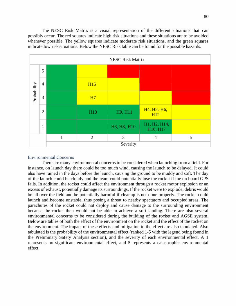
80
The NESC Risk Matrix is a visual representation of the different situations that can
possibly occur. The red squares indicate high risk situations and these situations are to be avoided
whenever possible. The yellow squares indicate moderate risk situations, and the green squares
indicate low risk situations. Below the NESC Risk table can be found for the possible hazards.
NESC Risk Matrix
Pro
bab
ilit
y
5
4 H15
3
H7
2
H13 H9, H11 H4, H5, H6,
H12
1
H3, H8, H10 H1, H2, H14,
H16, H17
1 2 3 4 5
Severity
Environmental Concerns
There are many environmental concerns to be considered when launching from a field. For
instance, on launch day there could be too much wind, causing the launch to be delayed. It could
also have rained in the days before the launch, causing the ground to be muddy and soft. The day
of the launch could be cloudy and the team could potentially lose the rocket if the on board GPS
fails. In addition, the rocket could affect the environment through a rocket motor explosion or an
excess of exhaust, potentially damage its surroundings. If the rocket were to explode, debris would
be all over the field and be potentially harmful if cleanup is not done properly. The rocket could
launch and become unstable, thus posing a threat to nearby spectators and occupied areas. The
parachutes of the rocket could not deploy and cause damage to the surrounding environment
because the rocket then would not be able to achieve a soft landing. There are also several
environmental concerns to be considered during the building of the rocket and AGSE system.
Below are tables of both the effect of the environment on the rocket and the effect of the rocket on
the environment. The impact of these effects and mitigation to the effect are also tabulated. Also
tabulated is the probability of the environmental effect (ranked 1-5 with the legend being found in
the Preliminary Safety Analysis section), and the severity of each environmental effect. A 1
represents no significant environmental effect, and 5 represents a catastrophic environmental
effect.

81
Table 13. Environmental Hazards on the Rocket
Key Environmental
Concern
Impact Probability Severity Mitigation
E1 Wind Too much
wind could
cause the
rocket to go
off target and
sight of the
rocket could
be lost during
the flight
2 3 Delay launch
until the wind
dies down
and the Field
Safety Office
gives the go.
E2 Rain before the
launch causes
mud on launch
pad
Could cause the
AGSE and/or
the vehicle to
sink into the
mud, causing
complications
of the launch
1 3 Delay launch
until
conditions
are desirable
or move the
launch pad to
a different
area.
E3 Rain on launch
day
Could cause
complications
with the AGSE
equipment
1 3 Delay set up
until rain
stops and
the Range
Safety
Officer
gives the go
for launch.
E4 Too much
cloud cover
Too much
cloud cover
could make
locating the
rocket difficult
if the on board
GPS fails
1 2 Test the
GPS to
make sure it
isn’t faulty
as well as
make sure
the
conditions
for launch
are
desirable.
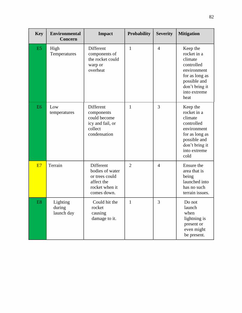
82
Key Environmental
Concern
Impact Probability Severity Mitigation
E5 High
Temperatures
Different
components of
the rocket could
warp or
overheat
1 4 Keep the
rocket in a
climate
controlled
environment
for as long as
possible and
don’t bring it
into extreme
heat
E6 Low
temperatures
Different
components
could become
icy and fail, or
collect
condensation
1 3 Keep the
rocket in a
climate
controlled
environment
for as long as
possible and
don’t bring it
into extreme
cold
E7 Terrain Different
bodies of water
or trees could
affect the
rocket when it
comes down.
2 4 Ensure the
area that is
being
launched into
has no such
terrain issues.
E8 Lighting
during
launch day
Could hit the
rocket
causing
damage to it.
1 3 Do not
launch
when
lightning is
present or
even might
be present.

83
Table 14. Environmental Hazards on the Environment
Key Environmental
Concern
Impact Probability Severity Mitigation
E9 Rocket
Explosion
If the vehicle
explodes it
could set fire to
the surrounding
area and/or
cause bodily
harm to the
bystanders
1 5 Make sure the
team mentor
helps in testing
the motor
significantly so it
is known for
certain that the
rocket is safe
E10 Unstable Rocket
Launch causing
damage to
surrounding
area
An unstable
launch could
cause the rocket
to go off its
targeted
trajectory and
could do damage
to the
surrounding area
1 4 Make sure the
launch pad is
very stable by
checking the
conditions of the
ground and
proper testing of
the AGSE
system.
Ell Parachutes
don’t deploy or
deploy too late
The rocket will
come crashing
down and
possibly cause
damage to the
environment of
the bystanders
2 4 Proper testing
of the black
powder charges
will occur to
ensure the
parachutes
deploy on time.
E12 Failure to
recover the
rocket
The rocket will
stay lying in the
surrounding
environment
causing potential
damage to farm
equipment and
wildlife.
1 2 Ensure GPS is
working as well
as tracking the
rocket through
the air.

84
Key Environmental
Concern
Impact Probability Severity Mitigation
E13 Fire from motor
exhaust
A fire could
happen if field
conditions are
dry enough,
causing damage
to the
surrounding
environment and
possibly the
bystanders
2 4 Ensure people are
clear of the
exhaust, there is a
large enough
blast plate to
deflect the flame,
and make sure
the surrounding
environment isn’t
significantly
flammable. A fire
extinguisher will
be located nearby
in case a fire does
occur.
E14 Battery acid
leak
Harmful acid
could get into the
ground causing
damage to the
field and possibly
local wildlife.
1 3 Make sure proper
cleanup
procedures would
be followed in the
event of a leak
E15 Vapors
produced from
soldering
During the
soldering of wires
lead oxide vapors
are produced that
are toxic to those
that inhale it.
4 1 The amount of
soldering that
needs to be done
will produce a
minimal amount
of harmful gas.
E16 Harmful
substances
getting into
groundwater
Improper disposal
of batteries,
solder, and
chemicals could
contaminate the
groundwater and
cause health
concerns for those
that use that
water.
1 4 All necessary
precautions are in
place to ensure the
proper disposal of
any substances
deemed harmful
to the
environment.

85
Key Environmental
Concern
Impact Probability Severity Mitigation
E17 Aerosol from
the spray paint
The propellant
used in spray
paint cans is
harmful to the
ozone layer and
can increase
global warming
5 1 The amount or
aerosol being
released into the
atmosphere is
minimal from the
few cans of spray
paint that will be
used. The cans
will also be
checked to ensure
they use LPG
propellant rather
than the more
damaging CFC.
E18 Improper
disposal of non-
biodegradable
material
Materials such as
plastics,
fiberglass, and left
over epoxy will
not degrade if sent
to a landfill, and
could be harmful
to animals.
2 2 Care will be
implemented to
ensure proper
recycling and
disposal of
leftover materials
Below the NESC Risk table can be found for the possible environmental hazards,
the guidelines of which can be found at the beginning of this section.
NESC Risk Matrix
Pro
bab
ilit
y
5 E17
4 E15
3
2 E18 E1 E7, E11,
E13
1 E4, E12 E2, E3, E6, E8,
E14 E5, E10, E16 E9
1 2 3 4 5
Severity
86
IV) AGSE/Payload Criteria
Selection, Design, and Verification of Payload
System Review (include sequential process order)
The Autonomous Ground Support Equipment (AGSE) system is designed to collect a
sample, place it firmly in the rocket, raise the rocket from a horizontal orientation to a vertical
orientation, and insert the igniter into the rocket motor. The sample will be collected from a
predetermined location and orientation, so the autonomous movements of the system are all
preprogrammed and are not dynamic. The full AGSE system can be seen in Figure 42 below.
Figure 42. Fully assembled AGSE system with the rocket in the 5 degree from vertical
position.
A successful run of the system will see the sample payload lifted from a predetermined
position 12 inches away from the AGSE and outer mold line of the launch vehicle and placed
safety into the hatch. Following this, the rocket will autonomously raise to a position 5 degrees off
of vertical. The igniter will be positioned to the top of the motor fuel grain within the rocket and
then the system will await launch approval from the range safety officer.
The AGSE system is divided into five subsystems which all function together to complete the
operations listed above. The remainder of this section contains a brief system description, while
the following sections describe each of these subsystems in greater detail.
The first of these subsystems is the sample collection crane, which contains the sample
collection arm with its imbedded hatch door. This system is required to perform the actions of

87
collecting the sample, and firmly attaching the sample and hatch door to the rocket body. The
sample collection crane consists of an aluminum base made primarily of the same 8020 rail used
for the launch rail system. The actual crane will be constructed on a rotary steel bearing, made
primarily of carbon fiber tubes. The two degrees of freedom of this crane will be controlled by
belts attached to stepper motors. An electromagnet will be placed on the end of the crane and used
to hold the hatch and clip system into place until it is powered down.
Second is the launch pad and rail system, which contains the main structure of the launch
pad, as well as the rail that is used to hold the rocket straight during its ascent. The launch pad and
rail system also includes the rail support placed several feet out from the pad itself which supports
the rocket and rail in the horizontal start orientation. The launch pad system is constructed of
aluminum 8020 rail with a 1” thickness. The launch pad itself is constructed of ⅜” steel to
withstand the blast of the rocket engine. The launch rail uses a thicker 1.5” 8020 rail to hold the
rocket stable during the first several feet of flight.
Next, the igniter subsystem is located on the base of the launch pad, and is used to insert
the motor igniter prior to launch. This system consists of a linear actuator that performs the
insertion, as well as a bent aluminum piece that is used to hold the igniter below the motor.
Fourth, the hatch and clip system that is used as the end effector of the robotic crane. The rocket
hatch is included within this system, as it is directly used to pick up the sample before being
attached to the rocket. The hatch itself is made of blue tube, as it will be cut from the rocket body.
Magnets will be included into the top and bottom of this hatch piece to allow for attachment both
to the crane and to the rocket body.
The fifth subsystem is the electronics system which controls and powers all of the
components in the above three systems. This system is controlled by an Arduino and several motor
controls. A series of limit switches, resistors, LED’s, and momentary switches will also be
implemented to accomplish mission goals. Along with these, two stepper motors, two linear
actuators, and one electromagnet will be integral to the AGSE’s success. The electronics are all
powered by a 3 cell Lithium Polymer battery.
A step-by-step procedure for the AGSE system can be found below:
1. The robotic crane will start with the electromagnet situated above the hatch door.
2. Power is run through the system, activating the electromagnet and attaching the hatch to the
electromagnet.
3. The robotic crane will rotate to a position over the payload.
4. The vertical arm piece will lower and push the clips securely onto the payload.
5. The vertical arm will rise back up to a height just above the rocket.
6. The crane shall then rotate over to the vehicle.
7. The vertical crane piece will be lowered into the vehicle bay.
8. When the hatch door is flush with the vehicle, the magnets inside the rocket will grip the steel
on the hatch door
9. A tubular latch bolted on the inside of the rocket will slide and lock the hatch, securing it firmly
in place.
10. Power to the electromagnet will be shut off, releasing the hatch from the crane.
11. The vertical crane piece will be raised slightly, in order to avoid contact with the rocket when
the crane rotating away from the rocket.
12. The crane will rotate away from the rail system and vehicle.
13. The rail system actuator will raise the vehicle to a position of 5° off of the vertical.

88
14. The igniter system actuator will raise the dowel rod until the igniter is in the tube, triggering a
limit switch when enough pressure is applied.
Figure 43. Assembled AGSE system in horizontal position without rocket
Subsystem Overview
Drawings, analysis, test results, and integrity of design
Crane System
The base for the robotic crane system is a 1’ x 1’ x 2’ rectangular prism made up of 1”
square 80/20 rails. There is a 1’ square aluminum plate attached to the top of the base and a wooden
shelf mounted inside to hold electronics. A 4” steel turntable is mounted to the center of the
aluminum plate in which the crane arm is attached via an ABS plastic mount. This attached
segment of the crane is a vertical 1” square carbon fiber tube. A NEMA 17 stepper motor mounted
to the aluminum plate operates a pulley system attached to this carbon fiber segment, giving the
crane a full 360 degrees of rotation. The horizontal segment of the crane arm is a 1” square carbon
fiber tube mounted on top of the first segment. At the end of this tube are two aluminum plates,
where two vertical 0.25” diameter carbon fiber rods are run through. At the top end, the rods are
connected with an aluminum cap. At the bottom, they attach to the electromagnetic hatch system.
A NEMA 17 stepper motor is attached to the rear of the horizontal carbon fiber tube with a plastic
mount. This stepper motor controls a pulley system that extends above and below the horizontal
crane arm, through a slot cut in the first vertical carbon fiber tube, and attaches on one end to the
aluminum cap and at the other end to the mount of the electromagnetic hatch system. A diagram
of the robotic crane system is shown below in Figure 44 and Figure 45.

89
Figure 44. Top view of dimensions for AGSE (inches)
Figure 45. Side view of dimensions for AGSE (inches)

90
Figure 46. Robotic crane system to pick up the sample and place it in the rocket

91
Rail System
The job of the rail system is to first harbor the rocket horizontally, secured via rail buttons,
until the crane system secures the payload within the rocket; the system will then the raise the
rocket from its horizontal position to 5° off vertical for launch. When that final position has been
reached, a limit switch will be triggered to tell the Arduino computer to halt movement of the
actuator. Due to the design of the actuator, even when the power is cut to the actuator there will be
enough friction within the gears of the actuator itself to keep the rail secure and the actuator locked
into position. There is concern of the system wobbling as the rocket raises, due to the length of the
rail and the weight of the rocket. To address this problem there will be a stabilizing rail attached
to the base of the system extending in the same direction as the rail holding the rocket; this rail
will ensure that the center of gravity of the system is not outside the base railing causing the system
to tip over. This launch pad has been used previously by the team, and has been tested to not
wobble significantly in the out of plane directions.
Figure 47. Mechanism to lift the launch rail and rocket
The system is comprised of the following: an 8’ long 1.5” thick rail made from 80/20
aluminum, a linear actuator with an 18” stroke and 400 lbs of maximum output force all powered
by a 11.1 V LiPo battery, the stabilizing rail, and three hinges to connect the rail to the base plate,
the rail to the actuator, and the actuator to a base stabilizing rail.
The base of the actuator is placed about 4.60” in front of the hinge on the base plate and is
24.25” below it. The tip of the actuator is placed about 20.09” along the launch rail giving the
actuator an unextended length of about 28.78”. For simplification in force calculation, the
maximum extended length of the actuator was calculated when the rail is perfectly vertical, as
opposed to 5° off vertical. At this extended length the actuator will be 39.11”. This means that
with the actuator extending at 0.6” per second, the total runtime of the system should be
approximately 17 seconds.

92
The team chose 80/20 aluminum for the rail because it is strong enough to support the
weight of the rocket, lightweight enough so as to not impose weight penalties as per competition
restrictions, and it is relatively cheap and reliable. The 8’ rail weighs about 10.747 lb and has a
center of mass 4’ from the pivot point; the rocket weighs about 22.51 lb and the base of the rocket
will rest 6” above the pivot on the base plate. This puts the combined center of mass for both the
rocket and the rail at about 41.57” from the pivot on the base plate. The base stabilizing rail is
intended to keep the AGSE from tipping over so the rail will extend a little after this point to ensure
stability as the rail is relatively lightweight and does not add any volume to the system.
Using Python, the geometric constraints, and the weights of the components, the force was
found and plotted as an equation of time and can be seen below. The maximum force needed by
the actuator is only about 82.75 lb which is significantly lower than the previous, successful design.
This difference is due to the rail being ⅔ the length of last year’s and the rocket being both smaller
and more lightweight. The script for this calculation is located in Appendix D.
Figure 48. Force vs. Time for actuator lifting the rail and rocket
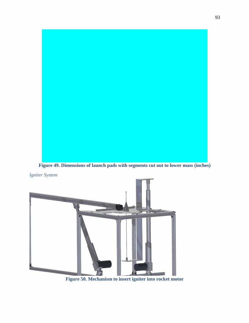
93
Figure 49. Dimensions of launch pads with segments cut out to lower mass (inches)
Igniter System
Figure 50. Mechanism to insert igniter into rocket motor
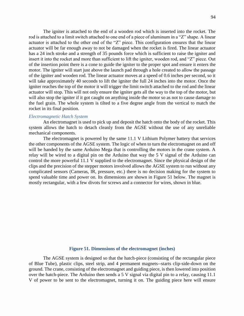
94
The igniter is attached to the end of a wooden rod which is inserted into the rocket. The
rod is attached to a limit switch attached to one end of a piece of aluminum in a “Z” shape. A linear
actuator is attached to the other end of the “Z” piece. This configuration ensures that the linear
actuator will be far enough away to not be damaged when the rocket is fired. The linear actuator
has a 24 inch stroke and a strength of 35 pounds force which is sufficient to raise the igniter and
insert it into the rocket and more than sufficient to lift the igniter, wooden rod, and “Z” piece. Out
of the insertion point there is a cone to guide the igniter to the proper spot and ensure it enters the
motor. The igniter will start just above the launch pad through a hole created to allow the passage
of the igniter and wooden rod. The linear actuator moves at a speed of 0.6 inches per second, so it
will take approximately 40 seconds to lift the igniter the full 24 inches into the motor. Once the
igniter reaches the top of the motor it will trigger the limit switch attached to the rod and the linear
actuator will stop. This will not only ensure the igniter gets all the way to the top of the motor, but
will also stop the igniter if it got caught on anything inside the motor so as not to cause damage to
the fuel grain. The whole system is tilted to a five degree angle from the vertical to match the
rocket in its final position.
Electromagnetic Hatch System
An electromagnet is used to pick up and deposit the hatch onto the body of the rocket. This
system allows the hatch to detach cleanly from the AGSE without the use of any unreliable
mechanical components.
The electromagnet is powered by the same 11.1 V Lithium Polymer battery that services
the other components of the AGSE system. The logic of when to turn the electromagnet on and off
will be handed by the same Arduino Mega that is controlling the motors in the crane system. A
relay will be wired to a digital pin on the Arduino that way the 5 V signal of the Arduino can
control the more powerful 11.1 V supplied to the electromagnet. Since the physical design of the
clips and the precision of the stepper motors involved allows the AGSE system to run without any
complicated sensors (Cameras, IR, pressure, etc.) there is no decision making for the system to
spend valuable time and power on. Its dimensions are shown in Figure 51 below. The magnet is
mostly rectangular, with a few divots for screws and a connector for wires, shown in blue.
Figure 51. Dimensions of the electromagnet (inches)
The AGSE system is designed so that the hatch-piece (consisting of the rectangular piece
of Blue Tube), plastic clips, steel strip, and 4 permanent magnets--starts clip-side-down on the
ground. The crane, consisting of the electromagnet and guiding piece, is then lowered into position
over the hatch-piece. The Arduino then sends a 5 V signal via digital pin to a relay, causing 11.1
V of power to be sent to the electromagnet, turning it on. The guiding piece here will ensure

95
consistent orientation of the hatch-piece when attached to the electromagnet. The crane then moves
this whole assembly (now consisting of clips, steel strip, permanent magnets, Blue Tube,
electromagnet and guiding piece) over top of the payload. The assembly is then lowered onto the
payload, causing the clips to grab the payload and clip it into place. The crane then lifts upward,
and positions the apparatus over top of the hole in the rocket. The hatch-piece with attached
payload is then slowly lowered into its position. The permanent magnets on the hatch-piece will
help it snap into position, and the latches on the rocket will cause the hatch to lock into its proper
position in the rocket. The electromagnet is then shut off via the Arduino, and the arm of the crane
(now consisting of only the magnet and guide-piece) is moved out of the way of the rocket before
the rails lift it into launch position.
The piece of Blue Tube cut out to make the hatch is geometrically described as a segment
taken from a hollow cylinder. Seen from the top, it is a 6 inch by 2 inch rectangle with the 6 inch
side along the long axis of the rocket. The weight of the hatch-piece is approximately 0.03 pounds.
For the hatch, Blue Tube was chosen because the most logical way of making a hatch that fits
perfectly into a hole cut into the side of the rocket is to use the piece that was cut. Since it was
decided Blue Tube was the best material for the main body of the rocket, by extension, the hatch
was Blue Tube as well.
The steel strip is a 3” by 1” by 1/10” strip of metal attached to the underside of the hatch,
between the clips. Steel was chosen because it is cheap, common, and ferromagnetic. This piece
was added so that the electromagnet will have something to cling to on the hatch itself. The team
used plain steel and not permanent magnets so that when the time comes for the crane to let go of
the hatch, the bond could be easily severed by turning off the electromagnet, and not having to
worry about the hatch sticking to the crane. It is estimated to weigh approximately 0.02 lbs.
The purpose of the guide piece is to ensure that when the electromagnet picks up the hatch
and temporarily attaches it to the crane, that the orientation of the hatch and clips is the same every
time. This will allow more precision when fine-tuning the AGSE commands. The material for the
guide piece needed to be easy to work with, and strong enough to attach the vertical arm bar of the
crane to. The guide piece will be an arc of steel designed to fit over top of the Blue Tube. It will
be 1/10” thick, 5” long, and 1 ⅜” wide and have a weight of 0.20 lbs.
The use of ABS plastic in the clips was because the task required a strong material that
could be easily formed into the specific shape, and have some flexibility to it. Since the Illinois
Space Society has ample access to 3D printers, a 3D printable plastic was the obvious choice.
Additionally, using 3D printed ABS allows for cheap rapid prototyping, meaning many minor
variations of the gripper design can be tested, and the design can be fine-tuned for maximum
reliability. Weight estimates are 0.02 lbs each, 0.04 lbs for both clips combined. The exact weight
of the clips will be dependent on the 3D printing fill percentage that produces the most reliable
results.

96
Figure 52. Mechanism of the electromagnetic hatch and clips to pick up payload
Iron alloy magnets were significantly cheaper than their rare earth counterparts, and are
strong enough for the needs of the rocket. Additionally, the magnets could not be too strong, as
too strong of a magnet would run the risk of interfering with the flight electronics. They are 0.01
lbs each, a total of 0.04 lbs for four of them. Last year, two of these magnets were used to keep a
hatch door on a hinge shut. These were the same magnets in the same position relative to the flight
electronics. This produced no interference with the flight equipment. However, in the unlikely
event that testing reveals the magnets interfere with any flight electronics, the addition of the
mortice latches means the strength of the magnets could be decreased and the latches would still
hold the hatch door in place.
The mortice latches were a change added from PDR when one of the reviewers brought up
the concern that the magnets were not enough to prevent the hatch door from flying off during the
launch. Mortice latches were chosen for their reliability and one-way operation. They allow the
crane to easily slide the hatch into place, but make it incredibly difficult for the hatch to fly off
during launch. This system is speedy and effective, allowing a safer launch while only sacrificing
negligible AGSE speed. They weigh 0.22 lbs each. Dimensions are in Figure 53. The latches will
be modified so that they do not interfere with the rest of the operation.
Figure 53. Dimensions of the latches

97
System-Level Functional Requirements
Table 15. AGSE Requirements and Verification
Requirement Solution Component Verification
Launch vehicle must
be placed
horizontally on the
AGSE
The launch vehicle will
be placed onto the rail
in the horizontal
position and left to be
erected autonomously
Launch Rail A level will be used to check
that the rocket is horizontal
A master switch
must activate power
to all autonomous
procedures and
subroutines
The AGSE system will
include a master switch
which controls all
power distribution
Master kill
switch
The master kill switch will
only allow power to the
system when closed and will
immediately terminate power
once opened
A pause switch will
halt all AGSE
subroutines
The AGSE system will
include a pause switch,
enabling the safe pause
and resumption of all
AGSE activity
Pause switch Pause button will be
connected to the computer
that controls all AGSE
actions and procedures
The AGSE will be a
maximum weight of
150 pounds and no
more than 12 feet in
height x 12 feet in
length x 10 feet in
width
The AGSE will be
constructed to meet the
weight and size
requirements
All
components
The components will be
weighed and measured to
ensure the size and weight
are within the limits
The AGSE will
complete the
required tasks in the
required order
The AGSE will be
programmed to
complete the tasks in
order
Arduino The computer will be
programmed to complete the
required tasks in the required
order and the system will be
tested extensively to ensure
compliance
All AGSE systems
should be fully
autonomous
All AGSE components
will operate free from
human intervention
after the procedure is
started
Arduino A computer will have
preprogrammed instructions
to complete all necessary
AGSE actions and
procedures

98
Requirement Solution Component Verification
The AGSE system
will be designed to
theoretically be
operable in the
Martian environment
The AGSE system will
not include
magnetometers, sound
based sensors, GPS,
pneumatics or air
breathing systems
All
components
Once built the AGSE will be
verified to ensure gravity is
not used and no prohibited
components will be used
The launch vehicle
must have a space to
contain the payload
and seal the payload
containment area
The rocket payload bay
has been designed to
accommodate the given
payload size as well as
seal the vessel
completely after the
payload is placed inside
Hatch and
clip
The hatch covering and clip
will attach to the crane
picking up the payload and
by eliminating extra
components to allow for
maximum room inside the
rocket for the payload
The payload must
not contain any
means to grab it
outside of its original
design
The payload will remain
unmodified by the team
and will be kept in its
original state
Robotic
crane
There will be a robotic crane
to grab the payload so it
would be unnecessary to alter
the payload to complete the
payload retrieval
The payload must be
placed at least 12
inches from the
AGSE and outer
mold line of the
launch vehicle
The team will place the
payload at least 12
inches away from the
AGSE and the outer
mold line of the launch
vehicle
All
components
A measuring tape will be
used to ensure the payload is
12 inches away
Gravity-assist shall
not be used to place
the payload within
the rocket
The payload will be
placed in the rocket
without the use of
gravity using a claw and
lifting system
Clip A clip will be used to hold
the payload in place and the
payload will be pushed into
the clip
Each team will be
given 10 minutes to
complete the
autonomous portion
of the competition
The team will ensure
the full autonomous
portion will take
significantly less than
10 minutes as a safety
measure
Arduino The computer will be
programmed such that all
required actions are
completed within the time
frame

99
Requirement Solution Component Verification
A master switch
which controls
power to all parts of
AGSE must be
easily accessible
The AGSE system will
include a master kill
switch which directly
can cut power to all
systems, placed in a
safe location
Master kill
switch
Master kill switch will be
connected to the computer
that controls all AGSE
actions and procedures and
will be labeled clearly on the
control box
A pause switch
which terminates
AGSE actions must
be included and
easily accessible
A pause switch will be
placed on the AGSE
alongside the master kill
switch which will
terminate all AGSE
procedures
Pause switch Pause button will be
connected to the computer
that controls all AGSE
actions and procedures and
will be labeled clearly on the
control box
An orange safety
light must be
included which
indicates power is
on, flashing when
active and solid
while paused
The team will include
and orange safety light
on the main AGSE
system to display the
current state of the
system
Orange LED
light
The LED will be connected
to the computer that controls
the whole AGSE ensuring the
correct response for the
correct state
An all systems go
light must be
included to verify all
systems have passed
safety verifications
and the rocket is
ready to launch
The team will include
an all systems go light
that verifies that the
system has passed all
verifications and is
prepped for launch
LED light The LED will be connected
to the computer that controls
the AGSE actions and
procedures ensuring it will
light up at the correct time
Approach to workmanship
The Student Launch team is comprised of many students coming from many different
majors. With the majority of the team in Aerospace Engineering, the team is confident in the
calculations as well as the part selection for both the rocket system and AGSE system. Also, with
enough experienced members, the team can rely on their input to see what would work best on
certain occasions.
The individual subteams have dedicated times to meet and discuss, collaborate, and
propose solutions to the various problems faced and talk about how to achieve the goals set all in
a timely manner. The team has plans and deadlines due for each week in what needs to be done
and the subteam lead is there to help oversee the team’s schedule and to promote healthy discussion
among the teams. Despite following a rigorous schedule, the team will take time to double and
triple check calculations in order to minimize errors wherever possible as well as ensuring a
successful operation in the future. Whatever measurements members make, it will be made twice

100
so members will only have to cut once. Members test multiple times to make sure the repeatability
of the processes are not due to chance.
Overall, the Student Launch team demonstrates a professional, yet fun environment for
practicality and technicality. As a team working together on one project, the team works
efficiently, in a timely manner, and in the best way possible. The team is confident they will
succeed during the Student Launch competition this April.
Planned testing
Team members will conduct extensive tests on the AGSE components as the system
requires a high level of precision, tolerances for different situations, and many competition
requirements. The lifting mechanism and igniter system has been tested and successfully worked
in last year’s Student Launch competition. With the minor modifications added to this year’s
design, these functions will again be tested to ensure that it either has equal or better performance
than before. The robotic crane is a completely new design, so the team will go through extensive
testing of the mechanism. Specifically, the precision of the crane will need to be tested as its motion
needs to be accurate in picking up the payload and attaching the hatch onto the rocket. The
electromagnetic hatch system is a unique design and will need continuous testing, modifying, and
calibrating. As the construction of the AGSE progresses, tests will continuously be run to make
sure that everything works the way it was designed to. By conducting these tests, the team will be
able to find problems and fix them or improve the design. At the test launch of the rocket, some
components of the AGSE will be tested as well. The launch pad, lifting mechanism, and igniter
mechanism will be used at the test launch because it is easy to test, will provide useful feedback,
and is already mostly constructed.
Table 16. AGSE Testing Plan
Function Being Tested Method of Testing
Securing the payload in
the clip
Make sure the payload fits tightly into the clips and does not fall out.
Test manually by pushing the clips onto the payload and shake it
vigorously to ensure a tight grip. Also test the tolerance of the
placement of the clips so minor errors in the position of the crane
will not be critical to securing the payload
Crane can securely
hold on to the hatch
and payload while in
motion
Run through the process of picking up the payload and rotating the
crane. Make sure the crane can smoothly rotate while carrying the
mass. Attempt the motion with a slightly heavier payload for margin
and make sure the crane can pick up the competition payload easily.
After the crane has grasped the payload, shake the arm and try to pry
the hatch off the crane. It should not come come off easily while the
electromagnet is turned on.
Crane rotating to the
correct position
After programming the movement of the crane, make sure the
position can be accurately set and altered. Rotate the crane’s arm
towards the rocket and test if the placement of the arm will allow the
hatch to be attached to the specific part on the rocket body tube. This
process will be a continuous testing process where the team will
experiment with different inputs on the programming of the crane.

101
Function Being Tested Method of Testing
Hatch being securely
attached to the rocket
Attach the hatch onto the rocket in the configuration it will be during
the launch. Shake the rocket vigorously to ensure that the hatch is
attached securely and it does not fall off or move around during
flight.
Electromagnetic hatch
system successfully
works and does not
damage any electronics
on board
The electromagnetic hatch idea is a unique solution to the
competition requirements. Repetitive testing will confirm that the
mechanism successfully works. Other electronic equipment such as
altimeters and GPS trackers will be tested to make sure that they
won’t be damaged by the electromagnet.
Rocket can be lifted by
the linear actuator
Place the rocket onto the launch rail and place in the horizontal
position. Add at least 5 pounds extra to the expected rocket mass to
allow margin of error. Lift the rocket with the linear actuator and
make sure that the motion is smooth and continuous.
Launch pad not tipping
over during the lifting
of the rocket
Along with the testing process written in the box above, lift the
rocket with additional mass from the horizontal position. Observe
the launch pad base and make sure that it does not lean or tip over at
all.
Rocket obtaining the 5
degrees from vertical
position
Run through the lifting process of the rail and test to make sure the
actuator stops once the limit switch is triggered. After the actuator
stops, measure the angle of the launch rail with a level. Test to see if
the angle is near 5 degrees from the vertical. If not, adjust the
location of the limit switch and rerun the test until the 5 degrees is
obtained repeatably.
Igniter smoothly
entering the nozzle of
the motor
With the rocket on the launch rail in the 5 degrees from vertical
position, run the linear actuator that lifts the igniter. Observe and
make sure that the cone underneath the launch pad guides the
wooden dowel and igniter smoothly into the nozzle of the rocket.
Repeat tests to ensure that it works repeatably.
After the igniter is fully
inserted in the motor, a
launch control box can
successfully ignite the
motor
The only opportunity to test this will be during the test flight. The
AGSE launch pad will be used during this test flight and the lifting
and igniter system will be tested. After the AGSE has completed its
procedure, team members will check that the igniter is properly
inserted. The motor will then be ignited from a launch box to make
sure it properly fires.
The AGSE can be
paused
Test the pause switch on the control box at all significant times
during AGSE operations. Make sure that when the pause switch is
pressed, all components of the structure remains stably in place.

102
Function Being Tested Method of Testing
Linear actuator raising
the igniter stops after it
gets to the top of the
motor
Test to make sure that the actuator stops after the wooden dowel is
pushed down and triggers the limit switch. If that test is passed, test
process on a fake motor. Ensure that the wooden dowel smoothly
enters the nozzle and stops at the end of the fuel grain. If this test is
passed, test on the actual motor with only the wooden dowel and
make sure the fuel grains do not get damaged.
The AGSE can be
powered off completely
with a kill switch
Test the kill switch on the control box many times at different times
during the process. Make sure that when the pause switch is pressed,
all components of the structure remain stably in place.
Repeatability Run the entire process multiple times. After the process is completed
once, return all the components to the original position and rerun the
process. Make sure the process is easily returned to original position
and repeatable.
LED and switches on
the control box
Run through the AGSE procedure and test to make sure that the
correct LED lights turn on in the correct situations (run and pause).
Also test all the switches and make sure they send the correct
commands to the AGSE.
Assembly of the AGSE
in under 60 minutes
The AGSE team will practice assembling the entire AGSE structure,
aiming for a total time of 30 minutes. Because the team must
transport the AGSE in a few separate pieces, it must be reassembled
at the judging and the launch. Test to make sure that after each
assembly, the AGSE is stable and works as designed.
The time the AGSE
process takes is
minimized
The team will observe and time the autonomous procedure of the
AGSE system. The time should be at least less than 2 minutes 30
seconds from the team’s predictions. The team will attempt to
minimize the time it takes while maintaining the integrity of other
aspects of the system.
Launch pad can
withstand the effects
from the rocket motor
blast
This has been already tested with last year’s competition and test
launch. However this will be tested again at the test launch this year
to make sure the launch pad and rail is still in good condition.
Rocket smoothly leaves
the launch rail and the
launch buttons do not
get caught
Because the launch rail is in two parts, the attachment point can be
dangerous because the rail button may get caught. After the two
parts of the launch rail is put together, slide the rocket with its
launch buttons up and down the rail and make sure that it is smooth.
This will be tested prior to the test flight as well.

103
The AGSE system relies heavily on each individual subsystem’s success. Therefore, it is
imperative that each subsystem consists of reliable and reusable parts. The crane subsystem is built
on a 1’ x 1’x 2’ base, with a 4” roundtable mounted on top. The crane is composed of carbon fiber
tubes and rods, and attached with aluminum braces. These are known to be structurally sturdy and
lightweight, the driving attributes behind the team’s choice. The crane will be moved via 2 stepper
motors. Again, these are lightweight and compact, but more importantly they have the capability
to output more than the required torque to move the subsystem.
Both the igniter and rail subsystems consist of 80/20 rails and a single linear actuator in
each subsystem. The 80/20 rails are perfect for rail buttons and are easily worked with. They can
be attached together with simple aluminum or steel pieces and screws. The actuators are strong
and reliable. They can consistently output the same force at the same rate every time, drawing
exactly the same amount of power that the team’s LiPo battery can provide.
The final subsystem to consider is the hatch and electromagnet subsystem. The most
important thing the team needed to consider was the weight of this subsystem, since it can affect
the performance of the crane subsystem. Therefore, it is constructed of lightweight magnetic strips,
a guide system, and a reliable electromagnet. The electromagnet is ideal in picking up the payload
and releasing it as it can easily be turned on and off by allowing or disconnecting power.
Mass Statement
Table 17. Mass Statement for AGSE
Component Per Unit Mass [lb] Quantity Total Mass [lb]
Linear Actuator for Igniter System 4.00 1 4.00
MB3U Bracket 2.00 2 4.00
1515 Aluminum Launch Rail 72" 8.06 1 8.06
1515 Aluminum Launch Rail 24” 2.69 1 2.69
Launch Rail Hinge 2.00 1 2.00
Linear Actuator for Rail System 4.00 1 4.00
Electric Wires, Connectors, and LEDs 0.50 1 0.50
XT-60 Wire Connectors (1 pair) 0.32 20 6.40
Electronic Switches (Kill, Limit, Pause) 0.50 1 0.50
Blast Plate 25.00 1 25.00
Structure 80/20's 1010 Rail - 72” 3.10 11 34.10
Z Piece for Igniter System 2.00 1 2.00
3 Cell Lipo Battery 0.84 1 0.84

104
Component Per Unit Mass [lb] Quantity Total Mass [lb]
Bread Board 0.07 1 0.07
Arduino Mega 0.08 1 0.08
M/M Jumpers 0.03 1 0.03
Square Turntable 1.00 1 1.00
Carbon Fiber Bar Stock 0.05 1 0.05
12V Electromagnet - 110lbs 0.75 1 0.75
0.236 OD Pultruded Rod 0.13 2 0.26
Arduino Expansion Shield 0.08 1 0.08
Stepper motor controller 0.08 1 0.08
NEMA 17 Stepper Motor 0.75 2 1.50
GT2 Belt and Pulleys 0.25 1 0.25
1/4-20 0.500 screw and nut 10s 0.02 20 0.40
1/4-20 0.375 screw 10s 0.01 20 0.20
1/4-20 t-nut 10s 0.01 15 0.15
1/4-20 t-nut 15s 0.01 5 0.05
Square Carbon Fiber Tube 1.03 1 1.03
Black 3D Plastic 2.20 1 2.20
Total Mass 102.27
Manufacturing and Assembly
The AGSE system construction and modification has begun and significant steps will be
made in the following month to bring the system towards completion. The launch pad has been
modified to decrease weight, helping the AGSE fall more safely under the 150 lb total limit set by
the Centennial Challenge. Early modifications to the crane stand have begun, and will continue
with completion of the main structure as the next goal of the AGSE subteam.
Continued construction of the AGSE will focus on completing the modifications to the
existing structure prior to new parts arriving. Upon the arrival of the new parts, every effort will
be made to complete the full AGSE structure quickly, to enable ample time for the integration of

105
the electrical components of the system. Following this, the system will be tested extensively until
it is deemed to be sufficiently robust to complete its full set of actions reliably.
To complete the necessary goal of retrieving a simulated Mars payload, the AGSE team
came up with the crane design as described above. This design is simple enough in that it completes
a single task through a limited amount of simpler tasks, yet it is challenging enough to stimulate
critical thinking. It is compact, designed for easy deconstruction and reconstruction, and
lightweight due to the hollow, skeleton design and overall nature of the materials, such as the thin
carbon fiber rods used in the crane system. Finally, no part of the system relies on gravity, allowing
for reuse under many different scenarios.
Integration Plan
The way the AGSE system was designed requires the careful integration of all of the
subsystems to create a highly precise mechanism. The manufacturing and material choices for
these subsystems vary depending on what environment they will be in. The majority of the rail and
igniter systems are constructed from 80/20 aluminum. The rail itself will consist of a six foot and
two foot length of 80/20’s 1515 t-slotted rail that will be fixed together to make an eight foot long
launch rail.
The hinge for this rail is another one of 80/20’s aluminum products which will allow it to
withstand the heat from the blast. The blast plate has been constructed out of a quarter inch thick
piece of steel. The base stand that will support both the rail hinge and the igniter system will be
constructed out of various lengths of 1010 t-slotted rail due to the vast amounts of joints and pivots
available that can be integrated with this rail. Two aluminum pivots will also be used at each end
of the rails actuator to support the weight of the rail and the rocket.
A 36 inch by 5 inch piece of quarter inch thick aluminum plate has been bent into the “Z”
igniter piece by the use of a hydraulic or arbor press. The mount for the igniter system’s actuator
will be constructed by drilling a hole into a piece of 1010 rail and allowing the bottom of the
actuator to be securely fastened to it with a bolt. The spring on the other end of the “Z” piece will
be made out of sprung steel, which will be able to handle the harsh environment that it will
experience when the rocket launches. Attached to the base will be segments of the 1010 rail
sticking out in two directions to help prevent the system from tipping over. The 1010 t-slotted rail
will also be used to secure the base to the crane’s stand.
The stand will be constructed out of t-slotted rail to create a structurally sound stand that
will not bend or move. There will also be two plates below the crane that will be able to hold all
of the AGSE’s electronic components. All of these 80/20 and other aluminum parts will be secured
together using brackets and mounts that 80/20 produces to fit with its products. This will reduce
cost and the price of the components because there will be no need for custom machinery. All of
the nuts and bolts for these pieces will be made of either steel or aluminum so that they can
withstand the stresses involved. The manufacturing and materials involved in robotic system are
completely different from the other two systems. Most of the crane’s structure will be constructed
out of carbon fiber. This allows the crane to be lightweight yet strong. The segments of the crane
will be constructed out of one inch square tube, and one inch diameter tube. These segments will
also have a hole running down the length of them to allow the wires to be protected and hidden.
Precision of Instrumentation and Repeatability
When designing the system and choosing components proper integration was always taken
into consideration to ensure the repeatability of the processes of the system. There will be multiple
test of components on their own and the system as a whole to ensure it can run as desired many
times.

106
The AGSE will be designed to be tolerant to some inaccuracies in all segments of its
operation. In all cases, as much precision as was technically feasible was included in the design,
but as in all real systems, some level of inaccuracy will always exist. This section details the
considerations that went into creating the AGSE system in such a way that it was tolerant to these
kinds of small inaccuracies.
As a part of the payload collection system, a sample payload must be collected from a
prepositioned ground location, simulating the AGSE taking a sample from a Mars rover or
equivalent. This system must be able reliably rotate and lower itself to collect the sample. The
motor used in the crane has a precision of 1/1600 of a rotation. This high accuracy assures that the
crane will be able to both retrieve the payload and secure it in the rocket in every run of the system.
Despite this, the system features clips which are shaped to allow for large inaccuracies (~ 0.25
inches in any direction) in the placement of the sample or the rotation and lowering of the crane as
an added safety. The clip design will guide the sample into the desired orientation from any slight
deviations. The magnets used to hold the hatch and payload in place are strong enough that if the
crane were to be slightly off in placing it, the magnets on the rocket will be strong enough to snap
the hatch and payload into place
The rail lifting system, which will raise the rocket to five degrees from the vertical after
sample insertion, has several contingencies to account for uncertainty in measurements. The rail
has some freedom to move in the plane perpendicular to the desired lifting motion of the rail
causing some risk of missing the limit switch to stop lifting. To ensure the rail will hit the limit
switch, a set of aluminum brackets bent at an angle guide the rail into its correct position. This also
ensures the repeatability and consistency of the lifting process.
The accuracy of the five degree from the vertical measurement will be ensured by thorough
testing prior to actual use. This measurement is driven by the correct placement of the limit switch
that halts the raising of the rail. With the position of this limit switch correctly tuned, the rocket
should be able to be within 0.5 degrees of the desired angle based on past results.
For the igniter, a cone is used to guide the igniter into its correct position below the motor.
This cone will have bottom diameter of 2 inches to allow for 1 inch of imprecision in either
direction for the igniter tip. The wooden dowel rod that will be used to hold the igniter rigidly
inside of the motor will also be marked to show the correct depth to which the igniter must be
inserted. This will be inspected visually prior to launch to ensure the igniter is fully inserted
properly.
Electronics Subsystem
The entire electronics subsystem will be powered by a single 11.1 V 5200 mAh Flite Pro
LiPO battery, with all of the programming being operated through an Arduino Mega. The Arduino
will be wired up to a solderless breadboard, with all other electronic components wired up to said
breadboard. This includes the two Nema 17 Stepper Motors, an electromagnet, two linear
actuators, two limit switches, and two LED indicators. Finally, there will be a handmade, wooden
control box housing the safety switches and LED indicators. One indicator will be orange, lighting
up when there is power to the system. If the system is active, it will blink, and if the system is
paused it will stay a solid orange. The other LED shall be green to show when the system is finished
and ready to launch.
Along with the LED lights, the wooden controller has two switches, a master switch and a
pause switch. The master switch shall be placed in series between the battery and all other
components. With that in place, the operator of the AGSE system will then have the ability to cut
power to all AGSE components instantly in the case of an emergency. This switch will be used to

107
activate the system and later to completely shut it down. The other switch is a push-button pause
switch, which can pause the system at any time and then be resumed by triggering the switch again.
Due to the importance of the LED indicators and the switches, power will be supplied to LEDs at
all times and be constantly updated to match the state of the switches. Both limit switches and the
pause switch will have pull up resistors so that a steady signal is read by the computer. Further
LED’s may be added to ensure power is reaching all aspects of the AGSE system as well to show
that switches are in working order. The wattage at all of the limit switches and the pause switch
will be minimal because they are used for signals. The LED’s also have a small consumption of
100 mW per diode. For the master switch the largest wattage it would experience would be no
more than 200 Watts, the sum of the total power draw of all components.
For the sample retrieval system, two electric motors will be connected to motor controllers
that will in turn be controlled by the Arduino. The first of these stepper motors will be placed at
the base of the main tower for the crane, allowing the crane to rotate the horizontal arm from a
position over the payload to one above the hatch. The second would be higher up on the tower,
and through use of a belt will allow the crane to raise and lower vertical arm holding the hatch.
The lower motor is stationary and will not require any kind of special wiring considerations.
Wiring for the motor on top of the first vertical piece will be run up through the central carbon
fiber tube, allowing free rotation of the crane without putting the wires at risk of breaking.
An electromagnet will be attached to the end of the vertical bar, and will be used to pick
up the payload. The wiring for this electromagnet will be run up though the first vertical piece of
the crane, in an identical fashion to the upper-most stepper motor, from there, these wires will be
run along the horizontal arm of the crane and down to the electromagnet itself. The power for the
electromagnet will flow through a relay, allowing control over whether or not the electromagnet
is active. Sufficient length of wiring will be included to allow for the electromagnet to reach all
the way to the ground when picking up the hatch. When the crane is raised to place the hatch onto
the rocket, this wiring will be run over a horizontal bar which is located at the halfway point of the
crane, keeping it from being severed or getting in the way of operations.
The next subsystem is a linear actuator placed at the base of the launch pad with a limit
switch placed underneath the launch pad to be triggered when the actuator is 5 degrees off of the
vertical as desired. The wiring for these components has already been run in past years, and will
be run inside the upper channel of the 80/20 rail to avoid tripping hazards. Lastly, the igniter system
will also have a linear actuator and a limit switch to control its system, the wiring for these
components will be run in an identical fashion to those for the rail actuator. All of the wiring can
be seen in Figure 54.
The coding for all subsystems will be executed via the Arduino Mega. Each subsystem will
be isolated from one another, with a function for each task. No function will run without a proper
signal received from each previous task. That is, no subsystem will run unless all previous
subsystems successfully ran. This ensures safety through the knowledge that if one task fails, the
system itself stops. The crane will be programmed to move based on absolute angles, instead of
operation time or relative angles, so the crane will run to the exact positions each time. The linear
actuators run continuously, stopping when a limit switch is triggered, giving precise positions the
team can physically see and change when needed.
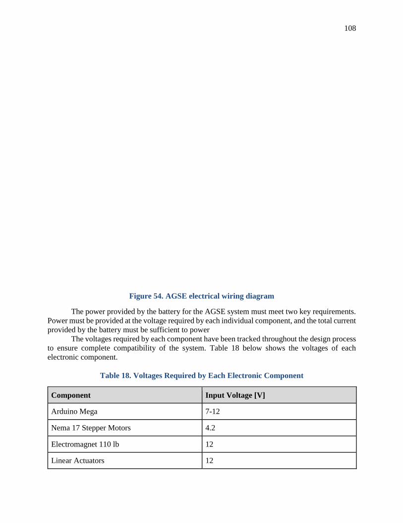
108
Figure 54. AGSE electrical wiring diagram
The power provided by the battery for the AGSE system must meet two key requirements.
Power must be provided at the voltage required by each individual component, and the total current
provided by the battery must be sufficient to power
The voltages required by each component have been tracked throughout the design process
to ensure complete compatibility of the system. Table 18 below shows the voltages of each
electronic component.
Table 18. Voltages Required by Each Electronic Component
Component Input Voltage [V]
Arduino Mega 7-12
Nema 17 Stepper Motors 4.2
Electromagnet 110 lb 12
Linear Actuators 12

109
As can be seen from the above table, all of the components can receive power from the
11.1 V battery being used to power the system, with the exception of the Nema 17 stepper motors.
These motors will be powered from an Arduino shield, which has a built in DC-DC converter to
take 11. V power and switch it down to the approximately 5 V required by the motors. As such,
all components will be receiving power at their required voltages from the currently planned
system.
The power modes of the system have also been identified to calculate the maximum current
draw required from the battery, to ensure the system is capable of operating in its full power mode.
These power modes are summarized in Table 19 below.
Table 19. Power Modes of the Electronic Components of the AGSE
Component Idle [A] Crane Operating [A] Linear Actuator
Operating [A]
Arduino Mega 0.25 0.25 0.25
Nema 17 Stepper
Motors (2)
0.00 3.00 0.00
Electromagnet 110 lb 0.00 0.50 0.00
Linear Actuator 0.00 0.00 5.00
Total 0.25 3.75 5.25
The table shows that the largest power requirement during any mode is when one of the
linear actuators is active. The linear actuators will not be active at the same time as any other major
component, as the movements they perform must be sequential. The lithium-polymer battery
chosen for the system is capable of providing power at a rate of 260 A continuously, more than
sufficient for the purposes of the AGSE system as designed.
Safety and Failure Analysis
To ensure the safety and success of the AGSE system during the competition judging, the
team must set up a plan to address these points. In terms of safety, the team has to keep in mind
the safety of members while working on the project, the safety of the components of the AGSE,
and the safety of the surrounding environment.
For the safety of team members while working on the AGSE system, the safety officer or
a subteam lead will be present at every construction event to supervise. All team members will
also be through a safety briefing by the safety officer. Because the construction of the AGSE
system involves dangerous power tools such as the drill press, circular sander, and electrical saws,
team members must be careful and attentive at all times. The safety of the team members is the
most important in regards to this project.
It is important to keep the AGSE system and surrounding environment safe as well. The
AGSE has critical components that are valuable and crucial to the mission that must be protected
such as actuators and electromagnets. Precaution will be taken to keep the components safe both
physically and electronically. Team members will also keep in mind the safety of the environment

110
around the AGSE during storage, construction, assembly, testing, judging, and launching. The
safety officer will make sure that it does not put anyone or the environment around at risk.
As with any project there are points that could fail. Team members have predicted areas
that could likely fail and have addressed those concerns. To make sure that any of the procedures
do not fail, the team will conduct extensive tests. There will be a lengthy process of trial and error
completing the full system successfully, but the team will persevere to ensure the AGSE runs
safely and successfully. Below is a table with specifics on the safety and failure analysis.
Table 20. Safety and Failure Analysis in Construction and Operation
Risk Impact Probability Mitigation
Use of power
tools in
construction of
AGSE
components
Team members could
be seriously injured if
tools are not used
properly.
Low Members will go through safety
training in using machining tools and
will follow the safety code. Safety
officer or team lead will be present at
all building events.
Use of lithium-
polymer
battery
Electronic components
can be permanently
damaged. Members
could be injured if
battery is not handled
properly.
Low When wiring, properly check the
specifications of electronic hardwares
and the circuits. Store and handle the
battery as instructed by the safety
precautions provided by the supplier.
The AGSE
base being
unstable
The rocket may not be
successfully lifted to
the launch position.
During launch,
complications may
occur if base is
unstable.
Low-
Moderate
Extensive testing lifting the rocket
and additional weight for margin.
Stress and load test on the base to
ensure any load or shaking that could
be involved in the operation would
deform the AGSE.
Components
from the
AGSE getting
loose during
launch
Loose components of
the AGSE during
launch could be
dangerous to those at
the launch site and the
environment close to
the pad.
Low Make sure that there are no loose
components on the AGSE that would
be dangerous and be blast off.
Conduct stress tests of many
components by shaking and adding
force. During launch, make sure
standard launch safety protocol is
observed and observers are far from
the launch pad.

111
Risk Impact Probability Mitigation
Construction
with carbon
fiber material
Improper safety
procedures when
handling carbon fiber
materials can cause
health hazards
Low Members working with carbon fiber
materials will be trained and educated
on how to handle the material
including safety gloves and masks.
The
electromagneti
c hatch is not
securely
attached to the
rocket body
If the hatch becomes
dislodged, misplaced,
or removed during
launch, the rocket will
be unstable and its
flight path will be
unpredictable and
dangerous.
Moderate Confirm that the hatch can be
securely attached to the rocket. Test
extensively by shaking the rocket and
purposely trying to remove the hatch.
It should not be easily removable.
Team members will review the rocket
between completion of the AGSE
process and launch.
Igniter system
gets caught on
the way up and
gets stuck
This may harm the
fuel grain of the rocket
and the igniter will not
be fully inserted into
the motor. This will
cause the motor to
ignite in an unusual
way.
Moderate The igniter system will have a
function in which if the limit switch
is triggered, the actuator will lower,
which will passively realign the
wooden dowel and go up again until
it is triggered. This will be repeated a
few times to make sure the igniter is
fully at the top of the motor. The
limit switch will extensively be tested
and made sure that it trigger properly
every time.
The launch rail
is unstable
When the rocket
leaves the rail, if the
rail is wobbly, the
rocket will not be able
to safely get off the
pad and may launch in
a different direction.
This may be dangerous
to people at the launch
and the environment
around the pad.
Low After the construction of the launch
pad and rail, the rail will be tested for
wobble. If the launch rail is too loose
and wobbly, supports will be added
and the bolts will be tightened. Team
members will forcefully shake the
launch rail and make sure it wouldn’t
interfere with the launch.

112
Risk Impact Probability Mitigation
A rail button
getting caught
on the launch
rail
The rocket will not be
able to safely get of
the launch rail. This is
mission critical and
could be dangerous to
the AGSE system
because it will
experience the burning
motor for an extensive
amount of time
Low Make sure the connection between
the two segments of the launch rails
are smooth and that the launch
buttons do not get caught. Test before
every launch, practice the assembly,
and test at the test launch as well.
AGSE
performs
unplanned
actions
If the AGSE runs
differently from
planned and acts
unusually, it may harm
critical components
such as actuators and
the crane components
Low In the case these things may happen,
a team member will be holding a
control box so they can pause the
process or shut down the power to the
AGSE. The control box will be
completed and tested before any
other tests are conducted.
Electromagneti
c hatch
interfering
with other
electronic
equipment
such as
altimeters and
GPS tracking
This would be mission
critical because if the
altimeter or GPS
tracking is harmed, the
rocket will not be able
to deploy parachutes,
measure data, or be
found.
Low-
Moderate
All the flight hardware will be tested
against the electromagnet holding the
hatch to make sure they do not get
harmed at the distance they will be in
during the AGSE process.
Storage of the
AGSE system
Because of the size of
the AGSE system, it
could be a hazard
unless stored and
worked on properly.
Also, the electronic
components could be a
hazard if not stored
property.
Low The AGSE system will be stored and
worked on in a spacious indoor area.
The University of Illinois Aerospace
Department provides student
societies with a working and storage
area. The area is locked so only
authorized persons can get in. It is a
dry, clean, cool, and well ventilated
area adequate for storage and work.

113
Payload Concept Features and Definition -
Creativity, Originality, and Uniqueness
Members of the Illinois Space Society have collaborated for weeks in order to create a
unique and creative design for the AGSE system. Due to the changes in the competition rules, the
team was forced to adjust the system to better fit the needs of this year’s challenge proposal. The
Centennial Challenge Mars Ascent Vehicle (MAV) prize requires a collection of a prepositioned
sample which will then be placed into a rocket for raising, igniter insertions, and finally, a launch.
The prepositioned nature of this sample allows for a simplistic design to be used for sample
collection.
The new and improved design for this year’s AGSE system will have the capability to
obtain a sample with a minimum of a foot away from the structure, allowing for pick up and then
insertion into the rocket without any reliance on gravity, as stated by the Centennial Challenge.
The crane-like system of the AGSE has been designed using a total of only two motors and an
electromagnet, making the system simplistic in design and application. Using only these two
motors for the crane-system, the team will be able to collect a sample and place it inside the rocket.
The unique and simplistic design allows for minimal points of failure to ensure a successful
operation of the system.
Suitable level of challenge
A significant redesign of the AGSE system was required to bring the system within the
constraints of the new competition. Improving and perfecting the already built structure will be a
challenge for the team as well.
The new crane system deals with a complex belt system and an advanced electronics
system. The electromagnetic hatch that picks up the payload and attaches itself onto the rocket
also poses mechanical and electronic challenges. Timing the entire procedure within the code and
finding the specific location at which the crane must be located will be designed, calculated, tested
for repeatability.
Most of the challenges the team faces lie in minimizing the mass and volume of the
structure while maintaining the time of the procedure to be carried out. The team needs to be able
to find the balance between these factors while also maintaining cost efficiency, manufacturing
ease, and reliability, all which prove to be difficult. However, collaboration between the team
members provides many unique and creative ideas in order to come up with solutions to the
challenges faced, all while still providing a solid design that will strongly compete with the
submissions from other universities and institutions.
Science Value The primary goal for the team is the safe retrieval of the payload, placement of the payload
in the rocket, and successfully preparing the rocket for launch by rising the rail system to 5 degrees
off the vertical and then inserting the igniter into the vehicle. An essential aspect of the AGSE
system is reusability. All parts shall be undamaged and not require human interaction between
each run. This is achieved by meticulous testing to assure no subsystem is damaged. With
everything being automated, there is no need for outside interference except during the initial
setup. All subsystems are isolated and monitored through the Arduino, to ensure that no subsystem
is a threat to any other subsystem. The team has also implemented LED lights to indicate activity
and power. This is a vital safety measure, both for the structure, and the team operating the
structure, giving a clear and concise idea of what is going on.

114
The purpose of the AGSE system is imitating a sample return mission on Mars, or
somewhere else with gravity significantly less than that of earth. Because of these constraints, the
AGSE is designed to be gravity independent, atmosphere independent, magnetic field independent,
and fully autonomous. The AGSE will be able to pick up a sample payload and place is in a rocket,
just as it would in a sample return mission. The conditions during the competition are not the same
as the conditions on Mars so the test is not perfect, however the design would still function in a
Martian environment. Some of the components would need to be swapped for similarly
functioning ones due to radiation and extreme temperatures but the cost of such components is too
high for this project.
The rocket is not the size of a rocket to land on Mars or elsewhere, but the design of the
payload holding system could be scaled up for an actual Mars mission rocket. The rocket used for
the competition will show the design used in the system could be implemented in a sample return
mission.
The mission will be considered successful if the AGSE system is able to pick up the sample,
secure it in the rocket, lift the rocket, and ignite the rocket all autonomously. The success will be
measured visually by seeing the payload is secured in the rocket and with a digital level to ensure
the correct final position of the rocket.
VI) Project Plan
Show status of activities and schedule
Budget plan
An itemized budget for the 2015-2016 Illinois Space Society Student Launch team can be
found below. This budget shows all of the parts that will be used by the team in the rocket, the
AGSE system, educational outreach activities, and travel to Huntsville, Alabama for the
competition. Many of the items used are already owned by the Illinois Space Society, but their off-
the-shelf costs have been included to calculate the total cost of all parts in the system, showing this
cost is well below the competition limit of $7,500. The value in the rightmost column is the total
cost to the Illinois Space Society, which must be obtained through a combination of University
and corporate sponsorship outlined in the Funding Plan section of this report.

115
Table 21. Budget Spreadsheet
Item Cost Each
[USD] Quantity
Total Cost
[USD]
Cost to Team
[USD]
Full Scale Rocket Material
4.00" X 16.5 Nosecone $21.95 1 $21.95 $0.00
Upper Airframe Tube $38.95 1 $38.95 $38.95
Iris Ultra 72" Parachute $210.00 1 $210.00 $210.00
Main Parachute Shock Cord $18.75 1 $18.75 $0.00
Coupler Body $39.95 1 $39.95 $39.95
Switch Band $38.95 1 $38.95 $38.95
Coupler Bulkheads $4.05 4 $16.20 $16.20
Body Tube Bulkheads $4.05 2 $8.10 $8.10
Rotary Switches $9.46 2 $18.92 $18.92
Charge Cups $1.50 4 $6.00 $6.00
Union 2648 Tubular Latch $17.35 2 $34.70 $34.70
Stratologger $79.95 3 $239.85 $0.00
Telemetrum $321.00 1 $321.00 $0.00
9V Battery $6.98 1 $6.98 $6.98
Trapezoidal Fins (3) $0.00 3 $0.00 $0.00
Booster Tube $38.95 1 $38.95 $38.95
Centering Rings (3) $4.05 3 $12.15 $12.15
Motor Mount Tube $29.95 1 $29.95 $29.95
75mm Motor Retainer $53.50 1 $53.50 $53.50
15" FruityChutes Drogue $50.00 1 $50.00 $50.00
Drogue Parachute Shock Cord $11.25 1 $11.25 $0.00
Rail Buttons $4.43 2 $8.86 $8.86
Motor (K1000T) Without Propellant $154.99 1 $154.99 $154.99
Proline Epoxy System 4100 Gallon $119.99 1 $119.99 $119.99
Motor Case RMS-75/2560 $235.40 1 $235.40 $0.00
Miscellaneous Parts $200.00 1 $200.00 $200.00
Subscale Rocket Material
Rocket Nosecone $11.95 1 $11.95 $11.95
Rocket Body $23.95 2 $47.90 $47.90
Coupler $8.95 1 $8.95 $8.95
Bulkhead $2.65 2 $5.30 $5.30
Centering Rings $4.75 2 $9.50 $9.50
Motor $23.39 1 $23.39 $23.39
Motor Mount Tube $16.49 1 $16.49 $16.49
Motor Retainer $24.61 1 $24.61 $24.61
Fins $28.34 1 $28.34 $28.34

116
Rail Buttons $3.07 1 $3.07 $3.07
AGSE Materials
Linear Actuator for Igniter System $119.99 1 $119.99 $0.00
MB3U Bracket $12.00 2 $24.00 $0.00
1515 Aluminum Launch Rail 72" $38.16 2 $76.32 $0.00
Launch Rail Hinge $24.95 1 $24.95 $0.00
Linear Actuator for Rail System $129.99 1 $129.99 $0.00
Red Stranded Wire 100' $9.95 1 $9.95 $0.00
Black Stranded Wire 100' $9.95 1 $9.95 $0.00
Green Stranded Wire 100' $9.95 1 $9.95 $0.00
XT-60 Wire Connectors (1 pair) $0.71 20 $14.20 $14.20
Green LED $0.59 3 $1.77 $0.00
Amber LED $0.59 3 $1.77 $0.00
Yellow LED $0.59 3 $1.77 $0.00
Kill Switch $11.98 1 $11.98 $0.00
Pause Switch $0.83 1 $0.83 $0.00
Limit Switch $0.99 4 $3.96 $0.00
Blast Plate $23.52 1 $23.52 $0.00
Structure 8020's 1010 Rail (per inch) $0.23 800 $184.00 $0.00
Z Piece for Igniter System $19.86 1 $19.86 $0.00
3 Cell LiPo Battery $49.95 1 $49.95 $49.95
Bread Board $2.31 1 $2.31 $2.31
Arduino Mega $44.95 1 $44.95 $44.95
M/M Jumpers $1.95 1 $1.95 $1.95
Square Turntable $2.12 1 $2.12 $2.12
Carbon Fiber Bar Stock $6.71 1 $6.71 $6.71
12V Electromagnet - 110lbs $117.00 1 $117.00 $117.00
.236 OD Pultruded Rod $16.99 2 $33.98 $33.98
Arduino Expansion Shield $17.95 1 $17.95 $17.95
Stepper Motor Controller $19.50 1 $19.50 $19.50
NEMA 17 Stepper Motor $22.90 2 $45.80 $45.80
GT2 Belt and Pulleys $16.69 1 $16.69 $16.69
1/4-20 .500 Screw and Nut 10s $0.50 20 $10.00 $10.00
1/4-20 .375 Screw 10s $0.39 20 $7.80 $7.80
1/4-20 t-nut 10s $0.21 15 $3.15 $3.15
1/4-20 t-nut 15s $0.27 5 $1.35 $1.35
Square Carbon Fiber Tube $158.99 1 $158.99 $158.99
Black 3D Plastic $21.55 1 $21.55 $21.55
Educational Outreach
Viking Model Rockets (pack of 12) $54.99 6 $329.94 $329.94
A8-3 Rocket Engines (pack of 24) $49.49 3 $148.47 $148.47
Estes Portable Launch Pad $13.77 2 $27.54 $0.00
Travel and Accommodations $2,475.00 $2,475.00 $2,475.00
Cost on the Pad $3,851.30 $2,321.00
Total Cost $6,326.30 $4,796.00

117
As can be seen in Table 21, the overall cost to the team will be $4,796.00. This amount
will be easily covered by the funding plan, which can be found in the following section. The cost
of this system, excluding travel, will be $3,851.30 including the material the team already owns.
This $3,851.30 is well below the $7,500 maximum, and the team is confident that it will remain
below that limit.
Funding Plan
As a technical project team under the Illinois Space Society, the Student Launch
Competition will be funded by the registered student organization. The funding plan developed by
the Illinois Space Society treasurer and approved by the executive board is shown below in Table
22.
Table 22. Student Launch Project Funding Plan
Source Amount in US Dollars
Student Organization Resource Fee 1,500
Engineering Council 1,050
University of Illinois at Urbana Champaign Aerospace Department 1,000
Corporate Sponsorship / Illinois Space Society 1,450
TOTAL 5,000
As it can be seen above, the funding for the Student Launch competition will come from a
wide variety of sources. The Student Organization Resource Fee (SORF) is a mandatory fee
collected each semester from all University of Illinois at Urbana Champaign students. The resource
fee is then allocated among Registered Student Organizations. The organizations go through an
application process after which the SORF board determines the amount of funding and the
organizations that receives the funding. These funds can be used for purchasing equipment and
travel expenses related to the project. The Illinois Space Society plans to request a funding of
$1,500 from SORF to be used both for equipment and travel expenses. Engineering Council is the
umbrella organization of all engineering Registered Student Organizations on campus. They do a
variety of things such as give awards, host events, and provide funding. For funding, Engineering
Council awards a grant of $525 to deserving organizations for projects each season. Illinois Space
Society will ask Engineering Council for the funding of Student Launch in the fall season.
Engineering Council also gives out separate funding for trips to conferences and other professional
events. Illinois Space Society will ask for a funding of $525 in the spring period to fund the trip of
team members to Huntsville, Alabama. The aerospace department at UIUC also provides funding
for technical projects by aerospace student organizations. ISS has received funding of $1,000 for
this Student Launch competition. This money will be used to purchase components to build the
AGSE and rocket. The remaining cost of $1,450 will be covered by corporate sponsors and the
Illinois Space Society. ISS is constantly searching for outside sponsors to help fund technical
projects, educational outreach, and other events. The technical director of ISS will specifically
market the Student Launch competition to try and get corporate or other outside sponsors for this

118
project. As it can be difficult to find outside funding and to estimate an amount, the rest of the cost
of this project will be provided by ISS. ISS and the Student Launch team will aim to reduce costs
and obtain funding from outside resources such as companies in the aerospace industry in
exchange for publicity. The team will consider putting advertising on hardware with stickers and
also inviting company representatives to have informational sessions on campus.
Timeline
The critical path to completion of both the rocket and AGSE components of the
competition can be clearly seen in the Gantt chart. Planned tasks are shown in blue, completed
tasks in green, behind schedule tasks in red, and tasks that are currently underway are in yellow.
It is clear from this chart that all activities are on or ahead of schedule with the exception of
modifications to be made to the igniter system. These modifications are relatively simple, and will
be a major focus moving forward to ensure construction is complete in time for the Flight
Readiness Review.
In most cases for both the Structures and AGSE teams parts will be ordered upon
completion of the Critical Design Review. Following this, parts will be assembled and constructed
as they arrive. Portions of the AGSE that require fewer new parts such as modifications to the
launch pad and other already existing components have already begun and will be completed prior
to the new parts arriving.

Gantt Chart

120
Educational Engagement Plan
Throughout the duration of Student Launch, the ISS Tech Team intends to actively engage
educators and students throughout the state of Illinois. The purpose of these activities will be to
not only teach the community about the principles behind rocketry and flight, but also to inspire
support and participation in the future of spaceflight technologies. Since the theory behind rocketry
is conceptually too abstract for younger students, engagement activities will revolve around hands-
on demonstrations of the basic principles of rocketry. Due to the nature of this project, the team
will also be able to demonstrate robotic theory to the community, which is an area of great interest
to young minds.
These activities will be distributed continuously throughout the project, and as such, the
outcome of activities will be evaluated in order to improve future events. Students, educators and
team members will be asked to respond to surveys requesting feedback for the events. The main
focus of this feedback will be determining the interest level of those involved, and the
understanding of principles demonstrated by the team. This will allow the team to adjust
presentations for future activities in order to better educate the community. An initial draft of this
feedback form is given in Appendix B. Through the team website the team will also implement a
contact system wherein participants of outreach events may request further information or
demonstrations from the team.
The Illinois Space Society and the College of Engineering offer numerous opportunities
for educational engagement activities. Particularly, the Illinois Space Society features an
Educational Outreach team which has established relationships with many local schools. This
offers a convenient starting point for engagement. The team intends on contacting schools in
Mahomet, Urbana, and Champaign, Illinois to offer educational services to students. Currently,
that team is developing an enrichment class curriculum that will provide Common Core
educational requirements. Additionally, the team intends on offering hands on demonstrations to
students at the University High School on campus and the high schools previously attended by
team members. This allows students to both give back to the local community and the institutions
that have previously educated the team. These activities typically take the form of optional after
school classes for students, or interaction with school science clubs. Additionally, the ISS Tech
Team has contact with local Boy Scout groups through previous engagements, and the team plans
on capitalizing on these opportunities for additional engagement.
Another major opportunity for engagement is the College of Engineering’s Open House on
March 11th and 12th. As this is only several days before the educational engagement deadline, the
team will strive to complete the required engagement activities before this time. Nevertheless, the
team still intends to participate in the Engineering Open House. This is a large event held every
year attended by thousands of students and community members. Although not all of these
attendees may be directly engaged by the ISS Tech Team, the Open House still provides an
important opportunity to interact with the community and inspire the next generation of engineers
and scientists. The team plans on operating continuous activities in order to facilitate indirect
interactions with the community. However, the team will also use this event to provide direct
interactions with students and educators. In order to do this, the team will hold scheduled
demonstrations at advertised times in order to allow structured hands-on demonstrations.
The Illinois Space Society has a variety of demonstrations and experiments for the
educational outreach events. Last year, the team constructed an orbital simulator with wooden legs,
flexible tent poles assembled in a circle, and a spandex fabric tightened to the tent poles. The center
of the fabric is pulled down by a weight and marbles are thrown in a circular path to simulate how
121
planets orbit and how gravity works. The Illinois Space Society also does a demonstration using a
space shuttle tile to explain how the shuttle had heat shields to protect the vehicle during reentry.
The tile is heated up by a blow torch and the temperature is then measured by a laser thermometer
to show that it remains at room temperature and conducts heat well. The society also does liquid
nitrogen demonstrations where the members teach about the cryogenic fuel tanks of rockets and
why they are used. In the demonstration, pennies, flowers, and balloons are frozen and then
crushed and marshmallows are frozen and handed out to the audience to eat. Also at educational
outreach events, society members show off their progress on their technical projects. The Illinois
Space Society exhibits many rockets from past rocketry competitions and poster boards that give
more information about the different technical projects.
The Illinois Space Society encourages all of its members to volunteer at the educational
outreach events. Many of the competitions the Illinois Space Society participates in requires
educational outreach similar to Student Launch. The educational outreach events that the Illinois
Space Society are involved in provide a great opportunity for team members to not only meet the
competition requirements but to be helpful in the community and to enjoy being advocates for
science and engineering.
V) Conclusion The Illinois Space Society is highly committed to the future of rocketry both from an
industrial and a hobbyist standpoint. The team is proud to once again compete in the Student
Launch competition and intends to do so for the foreseeable future. Team members from many
different majors and departments throughout the University have already dedicated several
hundred engineer-hours to the design and documentation of these systems. Most importantly, over
half of these team members are first or second year students with little to no previous rocketry
experience. Under the guidance of the team mentor and more experienced team members, these
new team members have already gained a significant amount of valuable insight into both high
power rocketry and, more importantly, the real world processes of design and engineering. This
personal growth will only be magnified once the construction of the systems themselves is
initiated. In previous years, the ISS team has treated this competition as an extracurricular activity
for students. Although this is technically still the case, the team intends to put forth a significantly
higher degree of effort and a more highly defined design than in previous years. Whether it is
through writing custom simulation code, presenting hand calculations, or a higher degree of detail
in models and drawings, the team has and intends to continue to work put forth significant effort
and treat this competition with the attention it deserves. Student Launch provides an opportunity
for students to participate in a high profile, real world engineering experience with many technical
challenges. This type of opportunity is not common in the world of undergraduate education, and
the ISS team does not take this experience for granted.

122
Appendix A Illinois Space Society Tech Team Safety Policy
All students are to sign and date the present document indicating that they read, understand, and will
abide by the contained policy before they enter the Illinois Space Society (ISS). These requirements apply
to day to day meetings, construction in and outside of the Engineering Student Projects Lab (ESPL),
testing, and any additional meetings that may occur as part of ISS Tech Team activities. The signed forms
are to be collected by the team safety officer, recorded, and submitted to the Technical Projects Manager. I. ESPL Rules: Required training to gain access to ESPL
General Lab and Electrical Safety training through the U of I Division or Research Safety is
mandatory for all individuals before they enter ESPL and participate in Design Council
supported projects. Both interactive training modules are online and available at the following
link: http://www.drs.illinois.edu/Training?section=GeneralLabSafety
Upon completion of the training modules the students must print, sign, date each form and give to
the designated safety officer who will keep record of their training and then give promptly to
ESPL Laboratory Supervisor. It is also required that all students read the present document and
sign and date it. Card access to ESPL will be granted after the ESPL Laboratory Supervisor has
the General Lab and Electrical Safety training forms and the present document signed and dated
on file.
Required training to use any tools/equipment in ESPL Students must receive training from The ESPL Laboratory Supervisor and fill out the
ESPL General Use Compliance Form and the ESPL Machine Shop use Compliance Form
before they use any tool/equipment on the respective forms or any potentially dangerous
tools/equipment. Tools shall not be brought into ESPL without the consent of the ESPL
Laboratory Supervisor. Any potentially dangerous tools or equipment not listed on the forms
should be added to the ESPL General Use Compliance Form list. Students may not work on
equipment until the ESPL Laboratory Supervisor has signed and dated the pertinent compliance
forms. A student must not use tools/equipment she/he was not trained for.
Each student group must designate a safety officer. The name, email, and cell phone
number of the safety officer must be distributed to each team member.
The safety officer must: Make sure that all individuals in the team are working in a safe manner and in compliance with
the Design Council Safety Policy. They will keep up to date record of the signed Safety Policy
forms for each team member
Be familiar with the daily activities of the team
Maintain a complete list of MSDS sheets for all potentially hazardous materials and their
respective quantities
All students must abide by the following ESPL General Use Rules:
1. A Laboratory Supervisor will oversee the Engineering Student Project Laboratory, including
the Machine Shop. 2. Students may not operate any power tool unless there is somebody else in the same work area
of the laboratory or shop. 3. Each student must wear safety glasses with side shield at all times while in any of the ESPL
work areas. 4. Hearing protection is required by anyone near loud equipment.

123
5. When in the work areas one must wear appropriate clothing: closed toed shoes, pants, no loose
clothing, jewelry, or hair is allowed that can potentially be caught in equipment. Do not wear ties,
rings, or watches. 6. Students must not lift heavy objects without the aid of an appropriate lifting device and hold
heavy objects in place using appropriate equipment such as jack stands. 7. When using power tools to cut materials, all parts must be properly clamped in a vise or
clamped to a table. Never hold a piece by hand when attempting to cut or drill it. 8. Never leave any tool or equipment running unattended. This includes electronic equipment,
soldering irons, etc. When you finish using anything, turn it off. 9. People welding or assisting in welding operations must wear welding masks or yellow tinted
safety glasses. You may only watch the welding process if you are wearing a mask. Students who
are welding or using grinders must use appropriate shields to protect others. 10. Compressed gases used for welding or other purposes pose several hazards. Users of
compressed gases must read and follow the recommendations of Compressed Gas Safety
available at https://www.drs.illinois.edu/SafetyLibrary/CompressedGasCylinderSafety 11. Shop doors must not be propped open. 12. Waste chemicals must be properly discarded, See the Laboratory Supervisor. 13. Store potentially hazardous liquids, chemicals and materials in appropriate containers and
cabinets 14. Students are responsible for the order and cleanness of their work space and benches
according to the rule: If you make a mess, clean it up. The same rule will apply to the common
areas of the laboratory including the designated “dirty” space, paint booth, and welding areas.
15. Work in a clean, uncluttered environment with appropriate amounts of work space and check
tools and workspace for problems/hazards before working with them. 16. Know the location of all fire extinguishers, emergency showers, eye rinse stations, and first
aid kits. 17. If you fill the garbage can, empty it in the dumpster outside. 18. The Laboratory Supervisor will decide how to proceed in the case of any situations not
covered by the preceding rules.
ESPL Machine Shop Rules (for all students using the ESPL Machine Shop):
1. Any user of the ESPL Machine Shop must read, understand, and abide by the ESPL General
Use Rules. 2. The Laboratory Supervisor controls card access to the ESPL Machine Shop. No student can
use any machine tool until he/she has demonstrated competence on that machine to the
Laboratory Supervisor. 3. No student may enter or remain in the Machine Tool Workshop unless accompanied by the
Laboratory Supervisor or a student who is authorized to use the Shop. The authorized user is
responsible for the visitor while he/she remains on the Shop. 4. Students may not operate any machine tool unless there is somebody else in the Machine Tool
Workshop. 5. Each student must wear safety glasses at all times. 6. When operating machine tools, long hair, long sleeves, or baggy clothing must be pulled back.
Do not wear gloves, ties, rings, or watches in the ESPL Machine Shop. 7. When using power tools to cut materials, all parts must be properly clamped in a vise or
clamped to a table. Never hold a piece by hand when attempting to cut or drill it. 8. Be aware of what is going on around you. 9. Concentrate on what you're doing. If you get tired while you're working, leave the work until
you're able to fully concentrate—don't rush. If you catch yourself rushing, slow down. 10. Don't rush speeds and feeds. You'll end up damaging your part, the tools, and maybe the
machine itself.
124
11. Listen to the machine, if something doesn't sound right, turn the machine off. 12. Don't let someone else talk you into doing something dangerous. 13. Don't attempt to measure a part that's moving. 14. Before you start a machine:
a. Study the machine. Know which parts move, which are stationary, and which are
sharp. b. Double check that your workpiece is securely held. c. Remove chuck keys and wrenches.
15. If you don't know how to do something, ask someone who does. 16. Clean up all messes made during construction
a. A dirty machine is unsafe and difficult to operate properly. b. Vacuum or sweep debris from the machine. c. Do not use compressed air.
17. Do not leave machines running unattended. 18. The Laboratory Supervisor will decide how to proceed in the case of any situations not
covered by the preceding rules.

125
Appendix B
Illinois Space Society Student Launch
Educational Feedback Form
How interesting was the demonstration? (1 – Boring, 10 – Extremely Interesting)
1 2 3 4 5 6 7 8 9 10
How much did you learn from this demonstration? (1 – Nothing, 10 – A Lot)
1 2 3 4 5 6 7 8 9 10
How interesting was the presentation? (1 – Boring, 10 – Extremely Interesting)
1 2 3 4 5 6 7 8 9 10
How much did you learn from this presentation? (1 – Nothing, 10 – A Lot)
1 2 3 4 5 6 7 8 9 10
What did you enjoy from your time with us?
What was your least favorite part of your time with us?

126
Appendix C
NAR HIGH POWERED ROCKET SAFETY CODE
EFFECTIVE AUGUST 2012
1. Certification. I will only fly high power rockets or possess high power rocket motors that
are within the scope of my user certification and required licensing.
2. Materials. I will use only lightweight materials such as paper, wood, rubber, plastic,
fiberglass, or when necessary ductile metal, for the construction of my rocket.
3. Motors. I will use only certified, commercially made rocket motors, and will not tamper
with these motors or use them for any purposes except those recommended by the
manufacturer. I will not allow smoking, open flames, nor heat sources within 25 feet of
these motors.
4. Ignition System. I will launch my rockets with an electrical launch system, and with
electrical motor igniters that are installed in the motor only after my rocket is at the launch
pad or in a designated prepping area. My launch system will have a safety interlock that is
in series with the launch switch that is not installed until my rocket is ready for launch, and
will use a launch switch that returns to the “off” position when released. The function of
onboard energetics and firing circuits will be inhibited except when my rocket is in the
launching position.
5. Misfires. If my rocket does not launch when I press the button of my electrical launch
system, I will remove the launcher’s safety interlock or disconnect its battery, and will wait
60 seconds after the last launch attempt before allowing anyone to approach the rocket.
6. Launch Safety. I will use a 5-second countdown before launch. I will ensure that a means
is available to warn participants and spectators in the event of a problem. I will ensure that
no person is closer to the launch pad than allowed by the accompanying Minimum Distance
Table. When arming onboard energetics and firing circuits I will ensure that no person is
at the pad except safety personnel and those required for arming and disarming operations.
I will check the stability of my rocket before flight and will not fly it if it cannot be
determined to be stable. When conducting a simultaneous launch of more than one high
power rocket I will observe the additional requirements of NFPA 1127.
7. Launcher. I will launch my rocket from a stable device that provides rigid guidance until
the rocket has attained a speed that ensures a stable flight, and that is pointed to within 20
degrees of vertical. If the wind speed exceeds 5 miles per hour I will use a launcher length
that permits the rocket to attain a safe velocity before separation from the launcher. I will
use a blast deflector to prevent the motor’s exhaust from hitting the ground. I will ensure
that dry grass is cleared around each launch pad in accordance with the accompanying
Minimum Distance table, and will increase this distance by a factor of 1.5 and clear that
area of all combustible material if the rocket motor being launched uses titanium sponge
in the propellant.
8. Size. My rocket will not contain any combination of motors that total more than 40,960 N-
sec (9208 pound-seconds) of total impulse. My rocket will not weigh more at liftoff than
one-third of the certified average thrust of the high power rocket motor(s) intended to be
ignited at launch.
9. Flight Safety. I will not launch my rocket at targets, into clouds, near airplanes, nor on
trajectories that take it directly over the heads of spectators or beyond the boundaries of
the launch site, and will not put any flammable or explosive payload in my rocket. I will
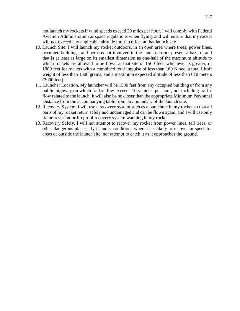
127
not launch my rockets if wind speeds exceed 20 miles per hour. I will comply with Federal
Aviation Administration airspace regulations when flying, and will ensure that my rocket
will not exceed any applicable altitude limit in effect at that launch site.
10. Launch Site. I will launch my rocket outdoors, in an open area where trees, power lines,
occupied buildings, and persons not involved in the launch do not present a hazard, and
that is at least as large on its smallest dimension as one-half of the maximum altitude to
which rockets are allowed to be flown at that site or 1500 feet, whichever is greater, or
1000 feet for rockets with a combined total impulse of less than 160 N-sec, a total liftoff
weight of less than 1500 grams, and a maximum expected altitude of less than 610 meters
(2000 feet).
11. Launcher Location. My launcher will be 1500 feet from any occupied building or from any
public highway on which traffic flow exceeds 10 vehicles per hour, not including traffic
flow related to the launch. It will also be no closer than the appropriate Minimum Personnel
Distance from the accompanying table from any boundary of the launch site.
12. Recovery System. I will use a recovery system such as a parachute in my rocket so that all
parts of my rocket return safely and undamaged and can be flown again, and I will use only
flame-resistant or fireproof recovery system wadding in my rocket.
13. Recovery Safety. I will not attempt to recover my rocket from power lines, tall trees, or
other dangerous places, fly it under conditions where it is likely to recover in spectator
areas or outside the launch site, nor attempt to catch it as it approaches the ground.

128
Installed Total
Impulse
(Newton-
Seconds)
Equivalent High
Power Motor
Type
Minimum
Diameter of
Cleared Area
(ft.)
Minimum
Personnel
Distance (ft.)
Minimum
Personnel Distance
(Complex Rocket)
(ft.)
0 — 320.00 H or smaller 50 100 200
320.01 — 640.00 I 50 100 200
640.01 — 1,280.00 J 50 100 200
1,280.01 —
2,560.00 K 75 200 300
2,560.01 —
5,120.00 L 100 300 500
5,120.01 —
10,240.00 M 125 500 1000
10,240.01 —
20,480.00 N 125 1000 1500
20,480.01 —
40,960.00 O 125 1500 2000
MINIMUM DISTANCE TABLE

129
Appendix D
Rail Calculations Python Script #all distances in inches, all weights in pounds, and all times in seconds
from math import cos #import relevant python tools and packages
from math import acos
from math import sin
from math import pi
import matplotlib.pyplot as plt
import numpy as np
f=24.682 #distance from hinge on base plate to hinge on ground
act_len_int=28.775 #initial actuator length
piv2piv=20.088 #distance from hinge on base plate to hinge on launch rail
da_dt=0.6 #how fast actuator extends in inches/second
act_len=np.linspace(28.775,39.111,100) #list of 100 points between initial and final actuator
lengths
alpha=[] #this list will be the angle between rail and actuator for every given length of the
actuator
def law_cos_ang(a,b,c): #use to find angle between rail and actuator using law of cosines
angle=acos((a**2+b**2-c**2)/(2*a*b))
return angle
for a in act_len: #fills 'alpha' list with appropriate angles in radians
alpha.append(law_cos_ang(a,piv2piv,f))
RocW=22.51 #weight of rocket
CGRoc=38.5 #CG of rocket from the pivot point on the base plate
CGRail=48.0 #CG of rail from pivot on base plate
RailW=10.7467 #weight of the 8' launch rail
TotW=33.2567 #weight of rail and rocket
CGComb=41.57 #CG of rail and rocket combined from pivot on base plate
act_force=[] #will be the list of forces to be graphed later
beta=np.linspace(0,pi/2,100) #angle off pi/2 that TotW acts w/ respect to the launch rail
momentCG=[]
#will be list of moments created by TotW, given actuator length. Measured from pivot at base
for angle in beta:
M=TotW*CGComb*cos(angle)
momentCG.append(M)
#determines the force required in the same direction as the actuator extends
for moment,angle in zip(momentCG,alpha):
AF=(moment/(piv2piv*sin(angle)))
act_force.append(AF)
time=np.linspace(0,(act_len[-1]-act_len[0])/da_dt,100) #plots actuator force as function of time

130
plt.plot(time,act_force,'ro')
plt.xlabel('Time(s)') #labeling axes
plt.ylabel('Force(lb)')
plt.title('Force vs. Time for Rail Lifting Actuator')
plt.show()

131
Appendix E
Rocket Profile Simulation Coded in MATLAB
%Flight Simulator for Illinois Space Society's NASA Student Launch Maxi-MAV
%competition, 2015-2016
%Based on Simulation created by David Knourek
%The current version of this simulator loads thrust curve values for the
%Aerotech K828, and K1000 motors, stored as .mat files called mass, thrust and time. These files
%hold vectors called Mass, Thrust and Time respectively, holding the obvious motor parameters.
These values are
%passed to the ODE45 ordinary differential equation solver. The program
%then parses the ODE solution to remove non-physical values that occur
%after the vehicle has landed, and plots the relevant data.
%For ease of use, calculations are completed in metric units, and converted
%to imperial units for output puropses
clc
clear
close all
%Load the Thrust curve characteristics
%These need to be altered if the motor is changed
%K1000
load('MassK1000.mat')
load('ThrustK1000.mat')
load('TimeK1000.mat')
MassK1000 = massimpulsewieghted(ThrustK1000,MassK1000);
%Store the thrust characteristics
%RHS are the vectors stored in the .mat files
%Mass is propellant mass
%This then loads the desired paramters into the variables used in ODE45
m=MassK1000;
T=ThrustK1000;
t=TimeK1000;
totalmass=10.2058;
%totalmass is mass of rocket with motor in kg
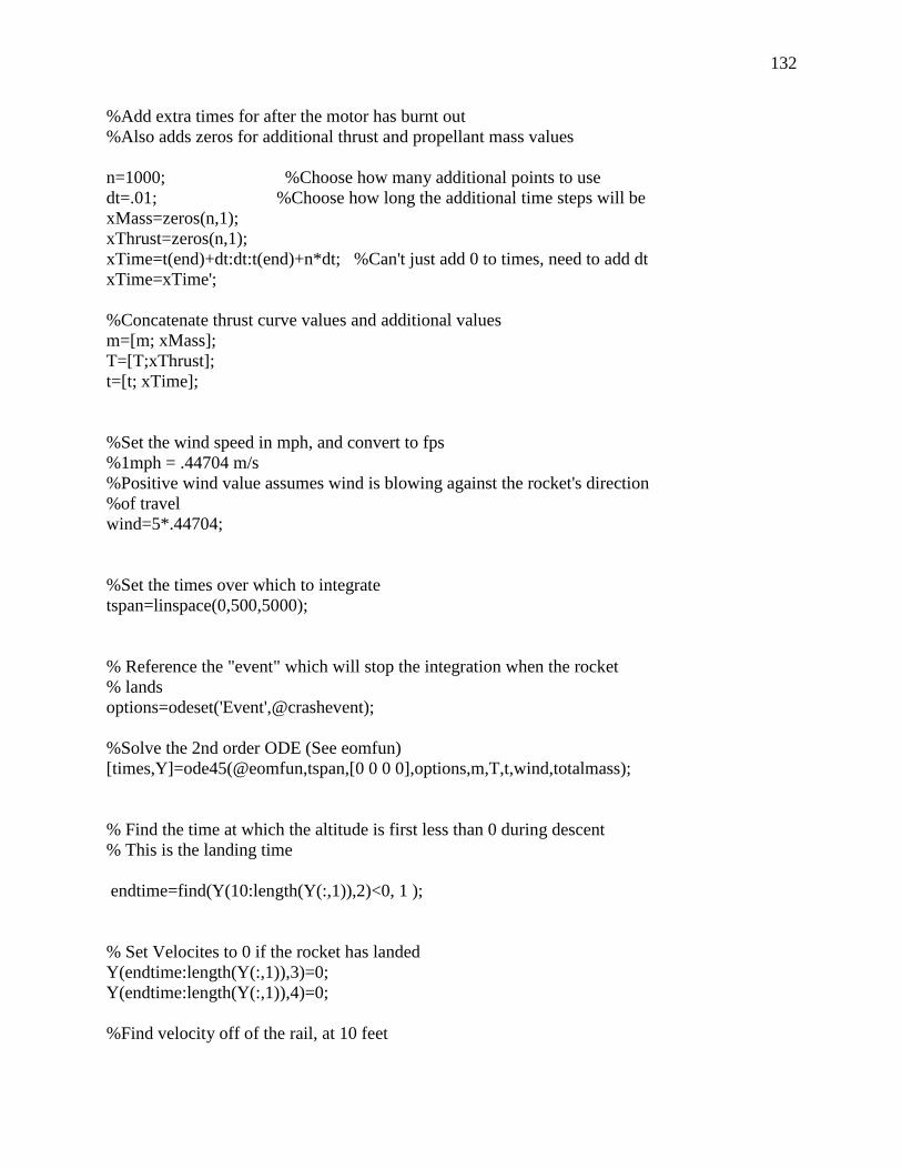
132
%Add extra times for after the motor has burnt out
%Also adds zeros for additional thrust and propellant mass values
n=1000; %Choose how many additional points to use
dt=.01; %Choose how long the additional time steps will be
xMass=zeros(n,1);
xThrust=zeros(n,1);
xTime=t(end)+dt:dt:t(end)+n*dt; %Can't just add 0 to times, need to add dt
xTime=xTime';
%Concatenate thrust curve values and additional values
m=[m; xMass];
T=[T;xThrust];
t=[t; xTime];
%Set the wind speed in mph, and convert to fps
%1mph = .44704 m/s
%Positive wind value assumes wind is blowing against the rocket's direction
%of travel
wind=5*.44704;
%Set the times over which to integrate
tspan=linspace(0,500,5000);
% Reference the "event" which will stop the integration when the rocket
% lands
options=odeset('Event',@crashevent);
%Solve the 2nd order ODE (See eomfun)
[times,Y]=ode45(@eomfun,tspan,[0 0 0 0],options,m,T,t,wind,totalmass);
% Find the time at which the altitude is first less than 0 during descent
% This is the landing time
endtime=find(Y(10:length(Y(:,1)),2)<0, 1 );
% Set Velocites to 0 if the rocket has landed
Y(endtime:length(Y(:,1)),3)=0;
Y(endtime:length(Y(:,1)),4)=0;
%Find velocity off of the rail, at 10 feet

133
railvelocity=interp1(Y(:,2),Y(:,4),8/3.28)*3.28;
%Output
fprintf('Rail Exit Velocity is %f feet/s \n',railvelocity);
P=00; %number of points after landing to plot
%Set times to plot over, start at ignition, end P timesteps after landing
plottimes=times;
%Extract flight characteristics and convert to feet
horizposition=Y(:,1)*3.28;
altitude=Y(:,2)*3.28;
MaxAltitude=max(altitude);
fprintf('Max Altitude is %f feet \n',MaxAltitude)
horizvelocity=Y(:,3)*3.28;
vertvelocity=Y(:,4)*3.28;
velocity=(horizvelocity.^2+vertvelocity.^2).^(1/2);
MaxVelocity=max(velocity);
fprintf('Max Velocity is %f feet/s \n',MaxVelocity)
fprintf('The Drift Distance is %f feet/s \n',abs(horizposition(end)))
%Load OpenRocket simulated values to plot a comparison
load('k1000.mat')
load('k1000wind.mat')
load('rocksimfull')
%Time(s) Altitude (ft) Vertical velocity (ft/s) Lateral distance (ft) Lateral velocity (ft/s)
%Plot Altitude
figure(1)
plot(plottimes,altitude,k1000wind(:,1),k1000wind(:,2),rocksimfull(:,1),rocksimfull(:,2),'linewidt
h',2)
xlabel('Time (seconds)')
ylabel('Altitude (feet)')
legend('Custom Sim','OpenRocket','RockSim')
%Plot Horizontal Position
figure(2)
plot(plottimes,abs(horizposition),k1000wind(:,1),k1000wind(:,4),'linewidth',2)
xlabel('Time (seconds)')
ylabel('Horizontal Position (feet)')
legend('Custom Sim','OpenRocket')

134
%Plot Horizontal Velocity
figure(3)
plot(plottimes,abs(horizvelocity)-20,k1000wind(:,1),k1000wind(:,5),'linewidth',2)
xlabel('Time (seconds)')
ylabel('Horizontal Velocity (feet/s)')
legend('Custom Sim','OpenRocket')
%Plot Vertical Velocity
figure(4)
plot(plottimes,vertvelocity,k1000(:,1),k1000(:,3),'linewidth',2)
xlabel('Time (seconds)')
ylabel('Vertical Velocity (feet/s)')
legend('Custom Sim','OpenRocket')
function dy = eomfun(t,Y,pmass,T,time,wind,totalmass)
%Flight Equations of Motion for Illinois Space Society's NASA Student Launch Maxi-MAV
%competition, 2015-2016
%Version 1.4
%The current version of these EOM takes as inputs the current position and velocity
%of the vehicle in the vertical and horizontal directions, and well as the
%thrust and the mass of the motor at all times, and the current time. It
%also takes the wind speed and total mass as imputs
%The program finds the current thrust, vehicle mass and drag, and uses
%these quantities to define the equations of motion. The derivatives of the
%input state Y are then passed out to ODE45, and used to solve the
%equations of motion.
%Based on Simulation created by David Knourek
%Define states
%Y=[x;y;vx;vy]
x=Y(1);
y=Y(2);
vx=Y(3);
vy=Y(4);
%Get x velocity wrt wind in the case that wind exists
%Positive wind value assumes wind is blowing against the rocket
vxrel=vx+wind;

135
%Find the direction of travel, used for direction of drag force
if y<100
theta=0*pi/180;
else
theta=atan2(vxrel,vy);
end
%if the rocket has landed, set velocities and accelerations to zero and return
if t>5&&y<0
dy=[0;0;0;0];
return
end
%Set constant values, metric units
g=9.81;
rho=1.225;
%Calculate Frontal Area for Drag
finheight= .0857;
finthickness=.00635;
finarea=finheight*finthickness*3;
diameterinch=4;
radiusm=diameterinch/3.28/12/2;
areabody=pi*(radiusm^2);
areanochute=areabody+finarea; %Area used for drag (in initial simulation)
area=areanochute;
%Determine the propellant mass at the current time, convert to kg
%interpolates between known propellant masses at known times
if t>2.55
propmass=0; %short circuit interpolation after burnout
else
propmass=interp1(time,pmass,t);
end
propmass=propmass/1000;
%calculate drymass using the full vehicle mass minus initial prop mass
drymass=totalmass-pmass(1)/1000;
%Calculate the current mass of the vehicle, including current propellant
currentmass=drymass+propmass;

136
% % Parachutes
%Adds drag and area for each event
if vy<0 && y>=(500/3.28) && t>5 %Drogue Deployment from Apogee to 1000 feet
cd=.8;
area=areanochute+pi*(1.67/(3.28*2))^2;
elseif vy<0 && y<(500/3.28) && t>5 %Main Deployment at 1000 feet and below
cd=1.89;
area=areanochute+pi*(6/(3.28*2))^2;
else
cd=0.75;
end
%Find Thrust at the current time
%Interpolated between the known thrust values at known times
if t>5
Thrust =0; %Short circuit the interpolation after burnout
else
Thrust=interp1(time,T,t);
end
%Converts the 2nd order ODE into two 1st order ODEs
%Sets the derivative of the first state to the 3rd state
%Sets derivative of 2nd state to the 4th state
xdot=vx;
ydot=vy;
%Calculates the velocity magnitude
%uses the relative x velocity wrt wind since this value is used for drag
v=sqrt(vxrel^2+vy^2);
%Calculates Drag
%To Do: Implement area as a function of orientation and travel direction
D=.5*rho*v^2*cd*area;
%Drag has to be limited to some finite value, no matter how large. Otherwise drag may
%have an instantaneously infitie value and crash the simulation
if D>20000000000000000
D=200000000000000;

137
end
%X acceleration equation of motion, a_x=(F_x)/m
% ax=(1/currentmass)*(Thrust-D)*sin(theta);
ax=(1/currentmass)*((Thrust*sin(-5*pi/180)-D*sin(theta)));
%Sets derivative of x velocity as x accleration
vxdot=ax;
%Y accleration equation of motion, a_y=(F_y)/m
ay=(1/currentmass)*((Thrust*cos(-5*pi/180))-D*cos(theta))-g;
%Sets derivative of y velocity as y acceleration
vydot=ay;
%Store the derivatives of the input state, to be returned to ODE45
dy=[xdot; ydot; vxdot; vydot];
end
function [ massnew ] = massimpulsewieghted( thrust,mass)
%Takes in propellent mass and thrust vector and weigths a new mass vector
% thrust = thrust curve values
% mass = mass of the motor
% massnew = a weighted mass vector based on thrust values
totalimpulse=sum(thrust);
totalmass=mass;
massnew=zeros(length(thrust)+1,1);
massnew(1)=totalmass;
for i=2:length(thrust)+1
massnew(i) = massnew(i-1) -(totalmass*thrust(i-1)/totalimpulse);
end
massnew=massnew(2:end);
end