Embed Size (px)
Citation preview
(i2) UnitedKadogawa
States Patent
IlllUlllllIllI II[lllllilUllllilllllllllllllll llllllllllllUUS006195203BI Ik 1 __ l (_ {_ _¢__1C__(
(10) Patent No.: US 6,195,203 B1
(457 Date of Patent: Feb. 27, 2001
'!
1L
(54)
(75)
(73)
APPARATUS FOR DIRECT OPTICAL FIBERTHROUGH-LENS ILLUMINATION OF
MICROSCOPY OR OBSERVATIONAL
OBJECTS
Inventor: Hiroshi Kadogawa, Pasadena, CA (US)
Assignee:
( * ) Notice:
The United States of America as
represented by the Administrator ofthe National Aeronautics and SpaceAdministration, Washington, DC (US)
Subject to any disclaimer, the term of this
patent is extended or adjusted under 35
U.S.C. 154(b) by 0 days.
(21) Appl. No.: 09/393,067
(22) Filed: Sep. 1, 1999
(51) Int. Cl.v ............................ G02B 21106; G02B 21/00
(52) U.S. CI .............................................. 359/385; 359/368
(58) Field of Search ..................................... 359/368, 385,359/387, 388, 390
(56) References Cited
U.S. PATENT DOCUMENTS
3,776,614 12/1973 Kloots et al..4,236,781 12/1980 Arimura.4,251,128 2/1981 Feinbloom.4,291,938 * 9/1981 Wagner ................................ 359/3874,329,015 5/1982 Feinbloom.4,527,870 7/1985 Esmay.4,537,477 8/1985 Takagi et al..4,617,467 * 10/1986 Senftle et al ..................... 250/461.1
4,725,727 2/1988 Harder et al ......................... 25012274,756,611 7/1988 Yonekubo et al..4,779,967 * 10/1988 Murphy et al ....................... 35913794,998,810 3/1991 Sander et al..5,312,393 * 5/1994 Mastel ....................................... 606/45,323,009 6/1994 Hams ................................ 250/458_1
5,548,113 * 8/1996 Goldberg et al ..................... 250/234
FOREIGN PATENT DOCUMENTS
63-191t14 8/1988 (JP).
OTHER PUBLICATIONS
Jenkins, Francis, A. and White, Harvey E., "Fundamentals
of Optics," McGraw-Hill, Inc., US, 1937, pp. 200-202.
Kingslake, Rudolf, "Optical System Design," Academic
Press, Inc., Orlando, Horida, 1983, pp. 187-193.
Smith, Warren J., "Modem Optical Engineering_The
Design of Optical Systems," McGraw-Hill, Inc., USA,
1990, p. 253.
* cited by examiner
Primary Examiner Thong NguyenAssistant Examiner Mark A. Robinson
(74) Attorne); Agent, or Firm--John H. Kusmiss
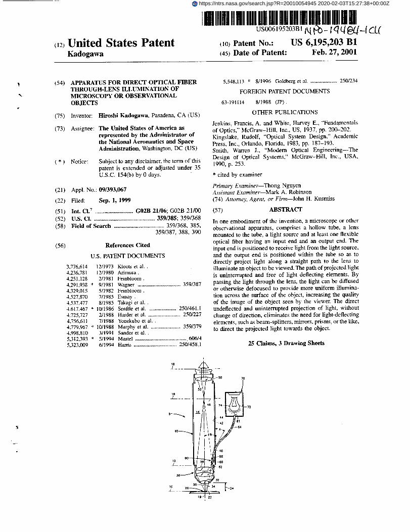
(57) ABSTRACT
In one embodiment of the invention, a microscope or other
observational apparatus, comprises a hollow tube, a lens
mounted to the tube, a light source and at least one flexible
optical fiber having an input end and an output end. The
input end is positioned to receive light from the light source,
and the output end is positioned within the tube so as to
directly project light along a straight path to the lens toilluminate an object to be viewed. The path of projected light
is uninterrupted and free of light deflecting elements. By
passing the light through the lens, the light can be diffusedor otherwise defocused to provide more uniform illumina-
tion across the surface of the object, increasing the quality
of the image of the object seen by the viewer. The directundeflected and uninterrupted projection of light, without
change of direction, eliminates the need for light-deflectingelements, such as beam-splitters, mirrors, prisms, or the like,
to direct the projected light towards the object.
25 Claims, 3 Drawing Sheets
https://ntrs.nasa.gov/search.jsp?R=20010054945 2020-02-03T15:27:38+00:00Z

66 t

U.S. Patent Feb. 27, 2001 Sheet 2 of 3 US 6,195,203 B1
12'
J
#
70'
60' _ 40'
__ 69'
3o._i ;', f_
20' 2'
7-
//I I _\""
FIG. 2

U.S. Patent Feb. 27, 2001 Sheet 3 of 3 US 6,195,203 B1
76--
76--
64 -_
--76
64
I
/
80
44 _
i //
nu
////
Ill/II/
V I
Is" /
il /
il I
I /
II
'4//
,W=z 84
FIC'.. 4
/
F

US 6,195,203 B 1
1APPARATUS FOR DIRECT OPTICAL FIBER
THROUGH-LENS ILLUMINATION OFMICROSCOPY OR OBSERVATIONAL
OBJECTS
ORIGIN OF THE INVENTION
The invention described herein was made in the perfor-
mance of work under a NASA contract, and is subject to theprovisions of Public Law 96-517 (35 USC 202) in which thecontractor has elected not to retain title.
BACKGROUND OF THE INVENTION
In order to adequately view an object by a magnifyingdevice such as a microscope, it is very important to suffi-
ciently illuminate the viewed object. Generally, as the mag-nification is increased, more light must be projected onto the
object. A lack of sufficient illumination will make the objectat least difficult, if not impossible, to observe. However,applying light to the object must be done in a manner which
does not substantially affect the observation of the object.That is, the process of adding additional light may actuallyinterfere with or obscure the user's ability to clearly observethe object.
One of the most common means to light an object is toback-light it. As the name implies, back-lighting simply
involves placing a light source behind the object such thatthe light passes from its source through the object and then
into the microscope. However, when viewing substantially
or completely opaque objects, the light must be applied tothe surface(s) being observed. Typically, opaque objects are
simply lit from a source positioned at the side of and
somewhat back from the object. This method of fighting is
normally referred to as "side illumination".
An inherent problem with side illumination is that as the
degree of magnification increases, the lighting becomes lessand less sufficient. This results from the fact that as the
magnification increases the distance from the objective lens
to the object decreases. This distance is known as the
'working distance'. High power microscopes generally have
working distances on the order of a tenth of a millimeter or
smaller. At such small distances, little light can be projectedfrom the side of the microscope onto the surface of the
object. Further, the light which does reach the object will be
directed very nearly parallel to the plane of the object's
surface, causing unwanted shadows and distortions. This is
especially problematic when the surface is not (relatively)smooth.
An alternative to side illumination is vertical illumination.
With vertical illumination light is transmitted from behind
and through the microscope's objective lens Onto the object.
This requires that light be projected from within the micro-
scope itself. After reaching the surface of the viewed object,
the light reflects off the surface and some of it travels back
up through the objective and eyepiece lenses to viewer. The
amount of light returning to the microscope depends on the
reflectiveness of the object's surface.
If light is projected from within the microscope itself
steps must be taken to avoid interference with viewing the
object. Perhaps the most common type of vertical illumina-
tor attempts to avoid interference by positioning its light
source off to a side of the microscope tube and using a
beam-splitter to direct the projected light down through the
objective lens and onto the object. That is, the light sourceis positioned off to the side of the tube and transmits its light
roughly perpendicular to the axis of the microscope, through
an opening in the side of the tube between the objective and
2
eyepiece lenses. A beam-splitter is placed about the micro-
scope's optical axis at generally a 45 degree angle so to
direct the light towards the objective lens, generally parallel
with the microscope's axis. The beam-splitter is typically a
5 partially silvered piece of glass which allows about half the
light to pass directly through and reflects the remaining light.
When the light is traveling back up through the microscope,
from the objective lens towards the viewer, the beam-splitter
again allows only amount half the light to pass through to the
to viewer and reflects back towards the light source the remain-
ing light.
Therefore, at best with a beam-splitter, the microscope
only allows about a quarter of the light emitted by the lamp
to reach the viewer. The stray light which is diverted by the
I5 beam-splitter must be controlled to prevent interference with
the viewer's image. To overcome these reductions in light,
an intense light source may be required. Of course, increas-
ing the size of the light source increases the cost and the heat
produced. Another problem with using a beam-splitter to
20 direct the projected light is that any defects or aberrations
present in the beam-splitter will affect the quality of the
viewer's image. Of course, the defects and aberrations can
be minimized by precision fabrication, which also increases
costs. Thus, the use of beam-splitters to direct light presents25 some significant problems.
In other vertical illuminator designs, mirrors and/or
prisms are used in place of beam-splitters to direct the light
projected from the light source. Although these elements
tend to project more of the light they direct, they (and their30 associated supporting su'uctures) act to block some of the
light returning from the objective to the viewer. These
elements must be positioned with the defocused region
existing behind the objective lens to avoid inference with the
image of the object. Even so positioned, the blocking of light35 will reduce the brightness of the object image. The larger the
mirror or prism, the greater the decrease in illumination will
be. Thus, the use of a mirror or a prism does little to
overcome the problems associated with the prior devices.
Further problems exist as beam-splitters, mirrors and40prisms are all inherently difficult to adjust to obtain proper
directing of the projected light. Adjustment may be critical
to the operation of the microscope not only to adequately
light the object, but also to avoid interference caused by
45 projected light reflecting off the back surface of the objectivelens and returning to the viewer. Some prior devices employ-
ing mirrors to direct the projected light have had to resort totilting the objective lens to avoid reflections. Obviously,
such a complicated modification is undesired as it prevents
the use of the illuminator in commercial microscopes with50 interchangeable objective lenses of varying powers.
A further problem is that the addition of beam-splitters,mirrors, and/or prisms and their supporting structures,
increases cost, size, weight and complexity. They make the
55 microscopes more fragile and susceptible to misalignments.
Also, the inclusion of the additional components can present
problems when the microscope is used in unique applica-
tions such as within a vacuum, where all components must
be specifically prepared to prevent out-gassing from certain
6o materials or trapped air.
Thus, a device is sought which will direct light in a
manner that provides sufficient illumination of the viewed
object without substantially blocking, reducing and/or dis-
torting the light traveling back up through the microscope to65 the viewer. In so doing the device should use the smallest
necessary light source to reduce cost and complexity. The
device must be easy to adjust to prevent unwanted reflec-

US 6,195,203 B 1
3
tions causing light interference at the eyepiece. The device
must also be compatible and easily integrated into existing
commercial microscopes having interchangeable objective
lenses of varying degrees of magnification. Further, thedevice must be capable of operating in specialized environ- 5
ments such as vacuums with minimal out-gassing. The
device must also be sturdy, durable and relatively low in
complexity, cost and weight.
SUMMARY OF THE INVENTION
In a microscope embodying the present invention the
output end of an optical fiber is oriented so as to directly
project light along a straight line through an objective lensdirectly to the object being viewed. By passing the light
through the objective lens, the light can be diffused or 15
otherwise defocused to provide more uniform illumination
across the surface of the object, increasing the quality of the
image of the object seen by the viewer. The direct unde-
flected and uninterrupted projection of light, without change
of direction, eliminates the need for light deflecting
elements, such as beam-splitters, mirrors, prisms Or the like,
to direct the projected light towards the object. Thus, the
light path from the lens to the object is uninterrupted by any
light deflecting elements. Being able to eliminate these lightdeflecting elements produces great advantages such as 25
reductions in cost, weight and complexity as well as
increases in durability and ruggedness, and allows the inven-tion to be used in conventional microscopes with minimal or
no modification.
Preferably, the optical fiber is flexible So that it is easily
bent to direct its output end towards the object without
having to move the input end.
By directly projecting the light, significantly less light islost to the losses or deflections of light typically occurring
with devices utilizing beam-splitters, mirrors and/or prisms.
This direct lossless light projection allows the use of the
smallest necessary light source (again reducing cost, weight
and complexity), greatly reduces the introduction of stray
light which may interfere with the imaging of the viewed
object, and minimizes reductions in illumination caused bythe blocking of returning light by the deflecting elements
themselves. The fact that no deflecting elements are needed
and that the output end can be positioned close to the
objective lens, and thus the object itself, allows the use of
less expensive optical fibers (e.g. multi-mode optical fibers)
which tend to have wider conical light projection than the
more expensive optical fibers. The elimination of elements
(e.g. beam-splitters) being placed across the path of the
returning object image also removes distortions imparted by
these elements. Further, the present invention is much easier
to adjust and align the projected light than are beam-
splitters, mirrors and/or prisms. Because of its limited num-
ber of components, the present invention can be configured
to operate in specialized environments such as a vacuum.
Placing the output within the defocused region of the
objective lens provides diffused illumination across the
surface of the object which improves viewing of the object.
The lens can be sized, shaped and mounted to the tube in
order to allow the viewer to view the object through the lens
and the tube. As such, the lens operates to both diffuse light
projected from behind and through the lens onto the object
and to provide for observation of the viewed object.
The lens can also be configured (sized and shaped) and
mounted to the tube to produce a magnified image of the
object for viewing by the viewer. To obtain additional
magnification the apparatus can also be configured as a
4
compound microscope. That is, the lens can be configured to
produce a focused magnified internal image within the tube.Then added to the apparatus is an eyepiece lens configuredand mounted to the tube to produce a further magnified
image of the internal image.
The optical fiber can enter the apparatus at any convenientlocation which allows the output end to be positioned to
project light through the objective lens and onto the object.
It is preferred that the optical fiber simply enter though a portin the side of the tube such that the output end will be within1othe defocttsed region and near or at the pupil plane of the
objective lens. This provides that the light projected onto theobject is diffused by the objective lens. In such a case, the
fiber enters the tube transversely and is bent inside the tubeso that the output end points longitudinally relative to the
tube and at the object. Preferably, the output end is orien-tated such that the light beam produced at the output end,
after passing through objective lens, illuminates the entire
viewed object surface.
The objective lens is mounted to the lower end of the20 hollow tube, near the object. The eyepiece lens in turn is
mounted on the upper end of the hollow tube such that it canmagnify the internal image produced by the objective lens
for viewing by the viewer.
The optical fiber can be held in position within the
apparatus by an adjustable support. This support is in turn
attached to the apparatus (e.g. to the tube). This allows the
position of the output end of the optical fiber to be varied.
The adjustable support can be a fixed or deformable mate-rial.
30 The objective lens can be contained in a microscope
objective which is a housing attached to the lower end of the
tube. The microscope objective can be detachable to allowdifferent lenses of various magnifications to be used. The
output end of the optical fiber should be positioned such that
35 the light it projects continues to pass through the objectivelens and is diffused on the object. The microscope objective
can be configured such that optical fiber passes into the
apparatus at the microscope objective and not through the
tube or any other portion of the apparatus. In such a40 configuration the optical fiber must be mounted to the
microscope objective so that the output end is positioned to
project light through the objective lens and onto the object.
With the microscope objective so configured, the optical
fiber can have a separating plug positioned at or near the
45 location where the optical fiber passes though the micro-
scope objective. The exterior portion of the optical fiber may
be separated from the microscope objective to allow easy
attachment and detachment (e.g. screw on or screw off) of
the microscope objective, allowing use of a variety of
50 microscope objectives each containing different lenses, to
change the microscope's magnification, and which each
contain their own optical fibers for illumination.
BRIEF DESCRIPTION OF THE DRAWINGS
55 FIG. 1 is a cross-sectional side view of an embodiment of
the present invention.
FIG. 2 is a cross-sectional side view of an alternative
embodiment of the present invention.
FIG. 3 is a cross-sectional side view of an embodiment of
60 the light source of the present invention.
FIG. 4 is a cross-sectional side view of an embodiment of
the illuminator of the present invention.
DETAILED DESCRIPTION OF THE
65 PREFERRED EMBODIMENTS
In the preferred embodiment the invention is in a micro-
scope where the output end of an optical fiber is oriented so
/

US 6,195,203 B1
5
as to directly project light along a straight path to anobjective lens and then onto the object being viewed. Bypassing the light through the objective lens, the light can be
diffused or otherwise defocused to provide more uniform
illumination across the surface of the object, increasing thequality of the image of the object seen by the viewer. The
direct undeflected projection of the light, without change ofdirection, eliminates the need for optical deflectingelements, such as beam-splitters, mirrors, prisms or the like,
to direct the projected light towards the object. Thus, the
light path from the lens to the object is uninterrupted by anylight-deflecting elements. Being able to eliminate these
light-deflecting elements produces great advantages such as
reductions in cost, weight and complexity as well asincreases in durability and ruggedness, and allows the inven-
tion to be used in conventional microscopes with minimal orno modification.
As seen in FIG. I, the microscope 5 is used to allow the
user to see a magnified image of an object 20. The micro-
scope 5 includes the following primary components: a
microscope objective 30, a microscope tube 40, an eyepiece50, an optical fiber illuminator 60 and a light source 70. Each
of these primary elements and their sub-elements aredescribed in detail herein.
Several planes are important to the configuration and
operation of the microscope 5. These include an object plane
10, a pupil plane 12, an intermediate focal plane 16 and an
exit pupil plane 18, as shown in FIG. 1. The object plane 10
is set at the position of the surface of the object being
viewed. The pupil plane 12 is set at the back of the
microscope objective 30. Typically, the optical fiber illumi-
nator 60 is positioned at or near (behind) the pupil plane 12.
The intermediate focal plane 16 is set back from the pupil
plane 12 and typically within the microscope tube 40. The
intermediate focal plane 16 is the position where the micro-
scope objective 30 focuses an internal image 48 of the object
20 magnified to a certain degree. Set between the pupil plane
12 and the intermediate focal plane 16 is the defocused
region 14. In the defocused region 14 the image of the object
20 is out of focus to a certain degree. The amount which the
image of object 20 is out of focus depends directly upon the
particular position within the defocused region 14. The
further forward from the intermediate focal plane I6 withinthe defocused region 14, the more out of focus the image
becomes. Likewise, if a focused image, such as a point lightsource, is projected from within the defocused area towards
and through the lenses in the microscope objective 30, its
image at the object plane 10 will be out of focus. Typically,
the defocused region 14 is set within the length of the
microscope tube 40. The exit pupil plane 18 represents the
location of the eye of the viewer. The microscope 5 also has
an optical axis 19 which typically runs along the center of
the microscope objective 30, the microscope tube 40, and
the eyepiece 50.
As shown in FIG. 1, microscope 5 views an object 20
which has an object surface 22 and which is positioned atobject plane 10. The distance from the vertex of the front
lens of the microscope to the object 20 is the working
distance 24. The length of working distance 24 generally
depends upon the magnification of microscope 5. Typicallythe higher the magnification, the shorter the distance
between the lens and the object 20. With some high-powerlenses this distance is on the order of a few tenths of a
millimeter.
The microscope objective 30 includes objective lens 32and has an objective front 34 and an objective rear 36. These
elements are shown in FIG. 1. The objective lens 32 operates
6
to form at intermediate focal plane 16 a magnified aerial(internal) image 48 of the object 20. The image 48 is then
magnified further by the eyepiece 50 for viewing by the user.The overall magnification of the microscope is the product
5 of the magnification of the microscope objective 30 and theeyepiece 50. Typically, a microscope will have a set of
interchangeable microscope objectives, so as to allow themagnification of the microscope to be changed. Interchange-
able microscope objectives must have a common mount so
that each microscope objective can be received by and10attached to the microscope tube 40. Also, the microscope
objectives must each position and/or shape their respective
lens or lenses (along optical axis 197 such that the internal
image 48 produced by each microscope objective 30
remains at the intermediate focal plane 16. In this manner,15the eyepiece 50 or its lens 52 does not have to be reposi-
tioned or otherwise modified to operate with different micro-
scope objectives.
The microscope objective 30 and objective lens 32 are
20 situated about the optical axis 19 such that the centerline of
objective lens 32 is aligned with the lens of the eyepiece 50.Although the microscope objective 30 can comprise just a
single objective lens 32, typically the microscope objective
30 will contain a combination of several lenses. The objec-
25 tive front 34 is the surface of the lens at the front of themicroscope 5, that is, the lens which is positioned closest to
the object 20. Where the front objective lens intersects with
the optical axis 19 is a front objective lens vertex 35. Theobjective rear 36 is the portion of the microscope objective
30 30 at or near the connection of the microscope objective 30to the microscope tube 40. The working distance 24 is the
length from the front objective lens vertex 35 to the object20.
Microscope tube 40 has a tube side wall 42, a tube interior
35 wall 44 and a port 46, as shown in FIG. 1. The tube side wall
42 defines the internal space which the observed image is
projected through by the microscope objective 30. When
necessary to prevent the introduction of stray light into the
microscope 5, the tube side wall 42 must be a continuous
40 opaque material. The interior of the tube side wall is the tubeinterior wail 44,
The port 46 is positioned and sized in the tube side wall
42 to allow an optical fiber 64 to pass through the side wall.
The size of port 46 should be close to the diameter of the
45 optical fiber 64 so as to prevent transmittal of stray light
from outside the microscope 5. Although the port 46 can beof any size, in one embodiment the diameter of port 46 was
set at 0.060 inches. To prevent stray light from entering themicroscope tube 40 at the port 46, a grommet of any opaque
50 material can be used to fit between the port 46 and the optical
fiber 64. Because the optical fiber 64 is limited in the radius
of any curvature imparted to it and typically must be bent in
order to aim the output end 62 towards the objective lens 32,
it is preferred that port 46 pass through the tube side wall 42
55 at a port angle A relative to the surface of the tube side wail
42. The port angle A can be any angle. However, the specific
value of port angle A depends on such factors as the
positioning of the output of the optical fiber, the location of
the port 46 along the length of the side wall 42, the amount
6o which the optical fiber 64 is curved, and the like. In one
embodiment the port angle A was set at 20 degrees, however,it is preferred that the port angle A be set so optical fiber 64
passes through tube side wall 42 nearly parallel with the
optical axis 19, such as with port angle A set at 10 degrees65 or less.
Although it is preferred that just one port 46 be used to
allow passage of a single optical fiber 64, if the use requires

US 6,195,203 BI
7
additional light to be projected onto object 20, the port 46
could be made wider to accept more than one optical fiber
64. More than one port 46 could be used.
Within tube 40, objective lens 32 projects an internal
image 48. The internal image 48 is a focused, magnified and
inverted image of object 20. The internal image 48 is located
at the microscope's intermediate focal plane l&
The eyepiece 50 operates to further magnify the internal
image 48 of the object 20. This magnification occurs by use
of an eyepiece lens 52. Eyepiece lens 52 can be a single lens
or a group of lenses. The eyepiece lens 52 must be sized,
shaped and positioned such that it acis to magnify the
internal image 48 of the object 20 so that the resulting image
at the exit pupil plane 18 is magnified and can be viewed bythe user.
The optical fiber illuminator 60 operates to transfer light
from a remote light source 70 to the interior of the micro-
scope 5. This is shown in FIG. 1. By projecting light from
within the microscope towards the objective lens 32, the
illuminator 60 causes light to pass through the objective lens
32 and be projected onto the object 20. Then, depending on
the reflectiveness of the object surface 22, a certain amount
of the light projected onto object 20 will reflect off the object
and pass back through the microscope 5 and to the user. The
illumination of object 20 caused by the illuminator 60 will
brighten the image seen by the user, allowing for improvedobservation.
The optical fiber illuminator 60 includes an optical fiber
input 61, an optical fiber output 62, an optical fiber 64 and
a support clip 66, as shown in FIG. 1.
The optical fiber 64 operates to transfer light from a
remote source to the interior of the microscope 5. The optical
fiber 64 can vary in length and dianleter depending on the
specific needs of the use for which illuminator will be
employed. For example, if the use requires more light to be
projected onto to the object surface 22 (e.g. because the
surface reflects little light), then a large diameter optical
fiber 64 can be used. However, since a large diameter optical
fiber 64 may (depending on positioning) block some of the
returning light, it is preferred that the diameter be kept closerto the minimum needed to transmit the amount of light
required. One end of the optical fiber 64 with the opticalfiber input 61 is attached to the light source 70. The optical
fiber input 61 is aimed towards the light source 70 so as to
pick up light to be transferred to the output end of the optical
fiber 64. In the preferred embodiment, the optical fiber 64
runs from the light source 70 through the microscope tube
side wall 42 via the port 46 set in the microscope tube sidewall 42. The optical fiber 64 terminates within microscope
5 at the optical fiber output 62.
At the optical fiber output 62 the light transferred by the
optical fiber 64 is projected. The angle of the output light
beam relative to optical axis 19 is an optical fiber output
angle B. With the output 62 directly aligned with the optical
axis 19, the output angle B will be 0 °. It is preferred that the
optical fiber 64 be positioned off to one side of the interiorof the tube 40, near interior wall 44. With the optical fiber
64 so positioned, output 62 may have to be set at some
output angle B to provide sufficient illumination of the
object 20 and to avoid reflecting light off the back surface of
the objective lens 32. Positioning the optical fiber 64 to one
side of the microscope tube 40 reduces blocking of light
reflected off the object 20 and traveling back through the
microscope 5 to the user.
The fact that the output 62 can be orientated directly
towards object 20 (no deflecting elements needed), and that
8
output 62 can be placed relatively close to objective lens 32(thus to object 20), allows a variety of different types of
optical fibers to be used in the present invention. That is, theoptical fiber 64 is not limited to single-mode fibers which
5 provide narrow conical light beam projection. Instead, theoptical fiber 64 can be a multi-mode optical fiber, which
provides more light output and a wider conical projection oflight. This is a significant advantage as multi-mode opticalfibers tend to be significantly less expensive then single-
10 mode optical fibers. This in turn reduces the costs of theoptical fiber 64 and of the microscope 5 or other device
incorporating the present invention. If more than one optical
fiber 64 is needed, they can be attached to a single clip 66or more than one clip 66 can be used.
15 The optical fiber 64 may be held in position within themicroscope 5 by the support clip 66. In one embodiment, the
support clip 66 is affixed between the microscope interior
wall 44 and the optical fiber 64 near its output 62, such that
the output 64 is held at or near the pupil plane 12. The
20 support clip 66 is attached to tube side wall 44 at a supportclip mount 68. The mount 68 includes two screws which
pass through holes in the clip 66 and into holes in side wall
44. The support clip 66 can be made of any suitable material
which secures the optical fiber 64 in place. It is preferred that
25 the clip 66 be made of a material that will retain the optical
fiber 64 in a relatively fixed position within the microscope
tube 40. However, in one embodiment the support clip 66 is
made of relatively thin and/or flexible material, such as
aluminum, to allow the clip 66 to be deformed to allow some
30 adjustment to the position and/or angle of the optical fiber
output 62. This adjustment can be made either internally orexternally. For an internal adjustment with the clip 66 as
shown in FIG. 1, the microscope objective can be removed
and the optical fiber 64 and clip 66 adjusted directly.
35 For external adjustment, as shown in FIG. 4, in one
embodiment of the present invention, the optical fiber is
supported by an adjuster 80. As shown in FIG. 4, the adjuster80 supports the optical fiber 64 and allows both the outputangle B and the position of the optical fiber 64 to be changed
40 by external manipulation by the user. Adjuster 80 has an
adjustment knob 82, an adjustment arm 84, an adjuster
support clip 86 and an adjuster mount 88. The adjustment
knob 82 is positioned and shaped to allow the user to
manipulate it to change the position of the optical fiber 64.45 The adjustment arm 84 is mounted to the support clip 86.
Support clip 86 is made of a flexible material to allow the
support clip 86 to be deformed and the angle B varied as the
adjustment arm 84 is slid into or out of the microscope tube
40 by the user. That is, as the adjustment arm 84 is pushed
50 inward the support clip 86 is bent outward and the angle B
is increased. Likewise, as the adjustment arm is pulled
outward, the support clip 86 is bent inward and the output
angle B is decreased. Mount 88 is slidably attached to the
microscope interior wall 44 allowing the mount 88 to move
55 vertically in the microscope tube 40. With the optical fiber64 attached to the support clip 86, the movement of the base
88 causes the optical fiber 64 to move vertically within thetube 40. The mount 88 can be slid by the adjustment arm 84
which is in contact with the mount 88. As the adjustment arm
6o 84 is slid upwards, the mount 88, support clip 86, and optical
fiber 64 move upwards. When the adjustment arm 84 ismoved downward, the mount 88, support clip 86, and the
optical fiber 64 are also moved downward.
The amount of change in the angle B and the distance
65 which the optical fiber can be moved along the microscope
tube 40 can vary depending on the specific embodiment's
needs. The adjustment arm 84 can be of a variety of
,/

US 6,195,203 Bi
9
configurations including having a screw shape which is
received by the mount 88 to allow for fine and retained
changes to the angle B by rotation of adjustment ann 84 by
adjusxment knob 82. In such an embodiment of the adjuster
80, the support clip 86 could be made of a relativelyinflexible material if it is hinged at the mount 88. The
adjuster 80 allows the position of the optical fiber 64 to be
changed to accommodate different microscope objectives 30
or other changes to the configuration of the microscope 5.
In an alternative embodiment, support clip 66 can be
configured as a hollow tube, having the optical fiber 64
running along the tube's interior. The support tube can be
made of a flexible material, such as a deformable metal, to
allow adjustment of the optical fiber 64 and its output 62.
The support tube can be mounted to the tube side wall 42 by
being received by the port 64.
Although the illuminator 60 can be placed in any position
along the interior of the microscope which allows for
projection of light so as to illuminate the object 20, it is
preferred that the illuminator 60 be positioned such that its
output 62 is placed within the defocused region 14 and
specifically near or at the pupil plane 12. Placing the optical
fiber output 62 in the defocused region 14 allows the light
projected from output 62 to be diffused by the objective lens
32. That is, the image of the output 62 is out of focus when
it is projected onto the object 20. The resulting projected
diffused light provides more even and constant illumination
across the object surface 22, improving the image seen by
the viewer. Placing the output 62 at or near the pupil plane
12 is preferred as this location tends to provide the most
diffusion of the projected light.
Another advantage to placing the optical fiber output 62
in the defocused region 14 is that the optical fiber 64 and the
support clip 66 will not be seen as a visible image by the
viewer. That is, even though the optical fiber 64 and clip 66
may be positioned within the path of the light traveling
through the microscope 5 from the object 20 to the viewer,
at the position of the optical fiber 64 and clip 66, the image
of the object 20 will be defocused and thus the image will
not be interfered with by the optical fiber 64 and clip 66.
Although the optical fiber output 62 can be set at an angleB from the optical axis 19, it is preferred that the optical fiber
output 62 be substantially aligned with axis 19 to maximize
the light projected onto object 20 and to minimize the
transmission of stray light within the microscope 5.Similarly, depending on the location of the output 62, it is
preferred that the output 62 be set at an angle B which
minimizes or eliminates light reflected off the back of
objective lens 32. Of course, reducing or eliminating infer-
ence caused by any such reflected light will improve the
viewer's image of the object 20. Although the output 62 can
be positioned at roughly any position across the interior of
the microscope $ (e.g. in a plane aligned with the optical axis
19), it is preferred that the output 62 be positioned near thetube interior wall 42. The closer to the interior wall 42, the
less the optical fiber 64 and it support clip 66 will block lightreturning from the object 20 to the viewer.
As shown in FIG. 1, the light source 70 includes a lamp
72 positioned within an enclosure 76 which accepts the end
of optical fiber 64 having the optical fiber input 61, such that
the input 61 is aimed so as to receive light from the lamp 72.Although a variety of lamps can be used, typically lamp 72will be a bulb with a lamp filament 74. Although thepreferred embodiment employs a lamp as light source 70,alternatively light source 70 can include any light emittingelement such as a laser illuminator, a laser diode or a
10
light-emitting diode. Also, light source 70 can be capable of
emitting light over a broad spectrum of light, including
visible light and/or infrared light. In one embodiment, the
light source 70 can include optical filters 76 which can be
5 moved into a position between the lamp 72 and the input 61
as is shown in FIG. 3. The optical filters 76 act to allow only
a select range of wavelengths of light to pass through into
the optical fiber 64. As can be seen in FIG. 3, the light source
70 can include a set of separate individual optical filters 76.
to In such an embodiment, each filter can be set to allow
transmission of a different range of wavelengths of light.
This provides the microscope operator with great versatility
as he or she can project onto the object surface 22 different
15 types of light as necessary for the particular application. In
one embodiment, the first optical filter below the lamp 72
can be a heat rejection filter and below the heat rejection
filter can be positioned a color filter. In this embodiment the
heat rejection filter acts to protect the color filter from the
2o heat produced by the lamp 72.
As shown in FIG. 3, when in use the optical filters 76 can
be moved into place in the light path between the lamp 72
and the optical fiber input 61. When not in use, the optical
filters 76 can be moved to one side, out of the path of light.25
The distance which the light source 70 can be located
away from the microscope 5 depends upon several factors
such as the amount of light needed to be projected onto the
object, the power of the lamp 72 and the type and diameter
3o of the optical fiber used.
An alternative embodiment of the present invention is
shown in FIG. 2. In this embodiment, the optical fiber
illuminator 60' is attached solely to a detachable microscope
35 objective 30' and not to the microscope tube 40'. This
arrangement of elements allows the illuminator to be used
with any standard microscope without any modification to
the tube or similar portion of the microscope. That is, a port
for the optical fiber does not need to be made in the side wall40 of the microscope 5'. In this embodiment, the optical fiber
64' runs from the light source 70' through a port 38' in the
side of the microscope objective 30'. The optical fiber 64' is
bent such that the optical fiber output 62' is aimed towards
the objective lens 32' while being positioned at or near the45pupil plane 12'. The optical fiber 64' is held in place within
the microscope objective 30' by a support clip 66' mounted
to the microscope objective 30'. In this configuration, light
is projected from the optical fiber output 62' through the
50 objective lens(es) 32' onto the object 20'. Since the output 62'
is positioned within the defocused area of the microscope,
the light projected onto the object 20' will be diffused. The
microscope objective 30' and optical fiber 64' can also be
configured so that an optical fiber plug 69' is located at the
55 port 38'. This is shown in FIG. 2. The optical fiber plug 69'
allows the optical fiber 64' to be detached at the microscope
objective 30', which provides for easier screw-on attachment
of the microscope objective 30' to the microscope tube 40'.
Thus, an advantage to these alternative configurations is that
60 the microscope objective 30' can replace any standard
(commercially available) microscope objective.
While the invention has been described in detail by
specific reference to preferred embodiments, it is understood
65 that variations and modifications thereof may be made
without departing from the true spirit and scope of theinvention.

US 6,195,203 B 1
11What is claimed is:
1. An apparatus for viewing an object by a viewer
comprising:A. a hollow tube;
B. a lens mounted to the tube;
C. a light source; and
D. at least one optical fiber having an input end and an
output end, the input end positioned to receive lightfrom the light source, and the output end positionedwithin the tube so as to directly project light along a
straight path to the lens to illuminate the object, suchthat the path of projected light is uninterrupted and free
of light-deflecting elements, wherein the output end is
positioned relative to the lens such that light projectedonto the object by the output end is not focused, so as
to illuminate the object with a diffused light.2. The apparatus of claim 1, wherein the lens is sized,
shaped and mounted to the tube to allow the viewer to viewthe object through the lens and the tube.
3. The apparatus of claim 2, wherein the lens is sized,
shaped and mounted to the tube to produce a magnified
image for viewing by the viewer.
4. The apparatus of claim 3, wherein the magnified image
is a focused internal image within the tube, and wherein the
apparatus further comprises an eyepiece lens which is sized,
shaped and mounted to the tube to produce a further mag-
nified image of the internal image for viewing by the viewer.
5. The apparatus of claim 4, wherein the further magnified
image is an at least five times enlargement of an unmagnified
image of the object.6. The apparatus of claim 1, wherein the lens is sized,
shaped and mounted to the tube to provide a defocused
region behind the lens and within the tube wherein an imageprojected from the defocused region onto the object is out of
focus, wherein the output end is positioned Within the
defocused region.7. The apparatus of claim 1, wherein the tube has a side
wall and wherein the at least one optical fiber enters the tube
through the side wall.8. The apparatus of claim 7, wherein the at least one
optical fiber is flexible.
9. The apparatus of claim 8, wherein the at least one
optical fiber bends to orient the output end to directly project
light along an uninterrupted straight path to the lens to
illuminate the object.
10. An apparatus for viewing an object by a viewer
comprising:
A. a hollow tube to allow viewing of the object, the tube
havinga lower end and _ upper efid;
B. an objective lens mounted to the lower end of the tube,
the objective lens producing a focused magnified inter-
nal image within the tube;
C. an eyepiece lens mounted to the upper end of the tube,
the eyepiece lens acting to magnify the internal image
for viewing by the viewer;
D. a light source; and
E. at least one flexible optical fiber having an input end
and an output end, the input end positioned to receive
light from the light source, and the output end posi-tioned within the tube so as to directly project light
along a straight path to the lens to illuminate the object.
such that the path of projeCted light is uninterrupted and
free of light-deflecting elements, wherein the outputend is positioned relative to the objective lens so that
the light projected onto the object by the output end isnot focused, so as to illuminate the object with a
diffused light.
12
11. The apparatus of claim 10, wherein the objective lens
is sized, shaped and mounted to the tube to provide adefocused region behind the lens and within the tube
wherein an inaage projected from the defocused region onto
5 the object is out of focus, and wherein the output end ispositioned within the defocused region.
12. The apparatus of claim 11, wherein the objective lenshas a pupil plane behind the objective lens and the output
end is positioned substantially at the pupil plane.13. The apparatus of claim 10, wherein the light source is
10remote from the hollow tape.
14. The apparatus of claim 10, wherein the at least one
flexible optical fiber is held in position within the apparatus
by at least one adjustable support attached to the tube, suchthat the position of the output end can be varied.
15 15. The apparatus of claim 14, wherein the adjustablesupport is comprised of a deformable material.
16. The apparatus of claim 10, wherein the at least one
flexible optical fiber comprises a plurality of flexible opticalfibers.
20 17. The apparatus of claim 10, wherein said light sourceis a laser.
18. The apparatus of claim 10, wherein said light source
is a light emitting diode.
19. The apparatus of claim 10, further comprising at least
25 one optical filter mounted between the light source and the
input end.20. An apparatus for viewing an object by a viewer
comprising:
A. a hollow tube to allow viewing of the object, the tube
30 having a lower end and an upper end;
B. an objective lens mounted to the lower end of the tube,
the objective lens producing a focused magnified inter-
nal image within the tube;
C. an eyepiece lens mounted to the lower end of the tube,35 the eyepiece lens acting to magnify the internal image
for viewing by the viewer;
D. a light source;
E. at least one flexible optical fiber having an input end
40 and an output end, the input end positioned to receivelight from the light source, and the output end posi-tioned within the tube so as to directly project light
along a straight path to the lens to illuminate the object,such that the path of projected light is uninterrupted and
45 free of light deflecting elements, wherein the at leastone flexible optical fiber is held in position within the
apparatus by at least one adjustable support attached to
the tube, such that the position of the output end can bevaried, wherein the adjustable support is comprised of
50 a deformable material; and
F. at least one adjustment arm connected to the at least one
adjustable support, whereby the position of the output
end can be varied by moving the adjustment arm.
21. An apparatus for viewing an object by a viewer
55 comprising:
A. a hollow tube to allow viewing of the object, the tube
having a lower end and an upper end;
B. a detachable microscope objective mounted to the
lower end of the tube, the microscope objective having
60 an objective lens, the objective lens producing a
focused magnified internal image within the tube, the
objective lens being sized, shaped and mounted to the
tube to provide a defocused region between the lens
and the focused magnified internal image within the
65 tube, such that an image projected from the defocused
region onto the object is out of focus, so as to illuminate
the object with a diffused light;
/

US 6,195,203 B 1
13
C. a eyepiece lens mounted to the upper end of the tube
which magnifies the internal image for viewing by theviewer;
D. a remote light source; and
E. at least one flexible optical fiber having an input end 5
and an output end, the input end positioned to receive
light from the remote light source, the output end being
positioned within the defocused region so as to directly
project light along a straight path to the lens to illumi-
nate the object, such that the path of projected light is 10
uninterrupted and free of light-deflecting elements.
22. The apparatus of claim 21, wherein the at least one
flexible optical fiber passes into the apparatus at the micro-
scope objective and the at least one flexible optical fiber is15
mounted to the microscope objective such that the output
end is positioned to project light through the objective lens
and onto the object.
23. The apparatus of claim 22, wherein the at least one
flexible optical fiber further comprises a plug separating a
first portion of the fiber from a second portion of the fiber, 20
the plug allowing transmission of light from the first portion
to the second portion of the fiber, the plug being positioned
at or near where the fiber passes though the microscope
objective, such that the first portion of the fiber may be
separated from the second portion to facilitate easy attach-
14
ment of the microscope objective and to allow use of other
microscope objectives.
24. An apparatus for viewing an object by a viewer
comprising:
A. a hollow tube;
B. a lens mounted to the tube;
C. a light source;
D. an adjustable support;
E. an optical fiber mounted to the adjustable support, the
optical fiber having an input end and an output end, the
input end positioned to receive light from the light
source, and the output end positioned within the tube so
as to directly project light along a straight path to the
lens to illuminate the object, whereby the path of
projected light is uninterrupted and free of light-
deflecting elements; and
F. an adjustment arm attached to the adjustable support for
varying the position of the optical fiber.
25. The apparatus of claim 24, wherein the output end is
postioned relative to the lens such that light projected onto
the object by the output end is not focused.

Jg