Embed Size (px)
Citation preview

ILM
INSTALLATION MANUAL & CHECK-OFF SHEET
ECN-M0322 Rev. 1.7, Date 10-23-2013 Part #90-0709-200
PALFINGER Liftgates, LLC. 15939 Piuma Ave., Cerritos, CA 90703
Tel (888)-774-5844 Fax (562)-924-8318
PALFINGER Liftgates, LLC. 572 Whitehead Road, Trenton, NJ 08619
Tel (609)-587-4200 Fax (609)-587-4201
Visit our website at www.palfinger.com for up to date information and notifications
If you received this product with damaged or missing parts,
Please contact PALFINGER Liftgates at (888)-774-5844

Company Information:
Company Name:
Advisor Name:
Truck/Trailer Year Make & Model:
Liftgate Information:
Liftgate Serial Number:
Liftgate Model Number:
Date of Purchase:
Date of Installation:

ILM Installation Manual
Table of contents
1 Safety Information .................................................................................................................... 1
2 Important Information ............................................................................................................... 2
3 Tools For Installation ................................................................................................................ 4
4 General View of Liftgate ........................................................................................................... 5
4.1 General Figures ............................................................................................................ 5
5 Installation Dimensions ............................................................................................................ 6
5.1 Important Dimensions ................................................................................................... 6
5.2 Installation Dimensions ................................................................................................. 7
5.3 Strength Requirements ................................................................................................. 8
5.4 Width Requirements ...................................................................................................... 9
6 Body Preparation ...................................................................................................................... 10
6.1 Rear Bumper ................................................................................................................. 10
6.2 Tow Hitch/Auxiliary Equipment ...................................................................................... 11
6.3 Flush the Sill (Sub- Framing) ......................................................................................... 12
6.4 Support Body ................................................................................................................ 14
6.5 Add Alignment Bars (Optional) ...................................................................................... 15
7 Liftgate Preparation .................................................................................................................. 16
8 Gate Installation ........................................................................................................................ 17
8.1 Hoisting the Liftgate ....................................................................................................... 17
8.2 Check Liftgate Dimensions ............................................................................................ 19
8.3 Welding Liftgate ............................................................................................................ 20
8.4 Trimming Excess Column .............................................................................................. 22
8.5 Installation of bracket for Control Unit ............................................................................ 23
9 Electrical Installation ................................................................................................................ 24
9.1 Main Power Connections............................................................................................... 24
9.2 Basic Wiring (Manual Closing) ...................................................................................... 25
9.3 Basic Wiring (Power Down Liftgate) .............................................................................. 26
10 Lubrication ................................................................................................................................ 27
11 Cycle Test and Final Inspection ............................................................................................... 29
11.1 Cycle Test and Bleed the hydraulic system. .................................................................. 29
11.2 Decal Placement and inspection ................................................................................... 31
11.3 Final Inspection Check List ............................................................................................ 34

ILM Installation Manual Chapter 1
Revision 1.7 - 1 -
1 Safety Information
This manual follows the Guidelines set forth in “ANSI Z535.4-2007” for alerting you to possible hazards and their potential severity.
This is the safety alert symbol. It is used to alert you to potential personal injury hazards. Obey all safety messages that follow this symbol to avoid possible injury or death.
! DANGER indicates an imminently hazardous situation which, if not avoided, will result in death or serious injury.
! WARNING indicates potentially hazardous situation which, if not avoided, could result in death or serious injury.
! CAUTION indicates a potentially hazardous situation which, if not avoided, may result minor or moderate injury.
CAUTION without the safety alert symbol is used to address practices not related to personal injury. (In this manual we use it to alert you to potentially hazardous situation which, if not avoided, may result in property damage.)
NOTICE without the safety alert symbol is used to address practices not related to personal injury. (In this manual we use it to alert you to special instructions, steps, or procedures.)
ILM Installation Manual Chapter 2
Revision 1.7 - 2 -
2 Important Information
Before Getting Started
“READ FIRST”
The ILM Plus is an industrial hydraulic lifting device. Performance and reliability are closely related to proper installation, battery cable connections, and grounding. All grounding surfaces MUST be cleaned, prepped, and sealed per this manual. “Cut to size” cables MUST be properly crimped and sealed as factory supplied. All connections MUST be dressed with dielectric grease or equivalent sealer.
• Read and understand the “Installation Manual” and “Owner’s Manual” in their entirety before starting your Installation.
• Refer to your truck manufacturer’s instructions before adding any auxiliary equipment. Installer is responsible for compliance with this manual, OEM and FMVSS requirements.
• Persons should never position themselves underneath the liftgate if it is not fully welded.
• All welding should be performed by qualified personnel per AWS standards.
• Always ground closest to your welding point to prevent arcing through moving parts or electrical parts.
• Contact PALFINGER Liftgates for Special Installations not covered in this Installation Manual.
• Do not paint cylinder shafts or nylon bearings (Use non-chlorinated brake cleaner to remove over spray)
• Final Check-Off-Sheet at rear of this manual MUST be filled out and kept in your records for future reference.
• Refer to owner’s manual for operation and maintenance information.
ILM Installation Manual Chapter 2
Revision 1.7 - 3 -
Improper operation of this liftgate may result in severe personal injury or death. DO NOT operate unless you have been properly instructed, have read and are familiar with the procedures in this manual. This manual has been designed to illustrate the steps needed for the basic installation of the ILM liftgate. It also provides safety information and simple preventive maintenance tips.
This manual is not intended for use as a repair or troubleshooting guide. Repairs should be performed by a PALFINGER Liftgates Authorized Service Center. This Manual has been designed for use in conjunction with the ILM series liftgate only which is designed for different capacities. There are four options available to determine the model and serial number of the installed liftgate:
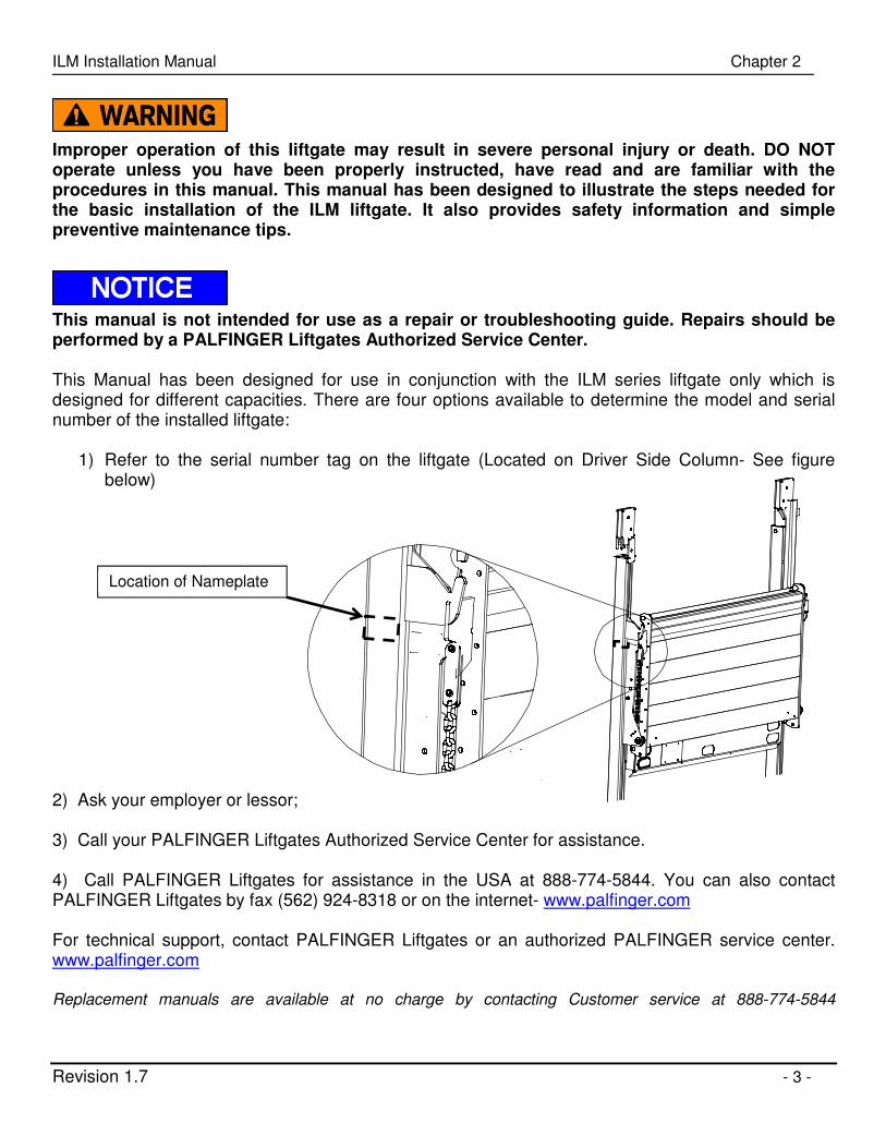
1) Refer to the serial number tag on the liftgate (Located on Driver Side Column- See figure below)
2) Ask your employer or lessor; 3) Call your PALFINGER Liftgates Authorized Service Center for assistance. 4) Call PALFINGER Liftgates for assistance in the USA at 888-774-5844. You can also contact PALFINGER Liftgates by fax (562) 924-8318 or on the internet- www.palfinger.com For technical support, contact PALFINGER Liftgates or an authorized PALFINGER service center. www.palfinger.com Replacement manuals are available at no charge by contacting Customer service at 888-774-5844
Location of Nameplate

ILM Installation Manual Chapter 3
Revision 1.7 - 4 -
3 Tools For Installation
SAE & Metric Wrench Set
Basic Screwdrivers Assorted Pliers Wire Crimp Pliers
Digital Multi-Meter Snap Ring Pliers Hammer SAE & Metric Allen key Set
½” Impact & Sockets
SAE & Metric Socket Set Assorted Drill Bits Floor Jack or Equiv.
Sm. To Med. Bottle Jack
Forklift or O/H Crane Hand Held Grinder Paint Gun & Accessories
Pry Bar 3/8 Drill Motor Grease Gun Heat Gun or Equiv.
Min. 250 Amp Welder
Cutting Torch or Equiv. 30” Pry Bar Rivets &Rivet Gun
Table 3-1: Suggested Installation Tools

ILM Installation Manual Chapter 4
Revision 1.7 - 5 -
4 General View of Liftgate
4.1 General Figures
Figure 4-1: ILM plus General View
LOAD CENTER OF
Side Chain
Hydraulic
Power Unit
Lift Cylinder
Safety- Storage
Latch
Control Buttons
Power Open/ close
Version
Platform Storage
Latch
Rail
Above Floor Option

ILM Installation Manual Chapter 5
Revision 1.7 - 6 -
5 Installation Dimensions
5.1 Important Dimensions
Minimum Bed Height dimensions are ALWAYS MAXIMUM LOADED TRUCK.
Maximum Bed Height dimensions are ALWAYS DRY UNLOADED TRUCK.
Ensure truck body or trailer rear door does not interfere with installation or operation of ILM plus
series liftgate. The ILM plus series cannot be installed with "barn" or "swing" type doors without
extensive modification.
It is not recommended to cut, torch, or remove support materials from rear sill of truck or trailer.
Installers are advised to sub-frame or flush sills as required. Removing gussets, stiffeners, light rings,
or other such support structures may VOID your truck/trailer warranty.
Call tech support before starting the installation if you have any questions or concerns on mounting dimensions or procedures… 888-774-5844

ILM Installation Manual Chapter 5
Revision 1.7 - 7 -
Max Bed Height 54"
Standard 51-1/2"
Above Floor 59-1/2"
Ground Clearence 18"
3" Column
10" Max
6" Box
Floor/Bed Height
5.2 Installation Dimensions
To determine liftgate compatibility, follow the steps below:
Steps:
1. Measure Floor Height: Measure the floor height of your truck and determine clearance requirements for
your liftgate platform size.
2. Verify Compatibility: Reference the chart below to ensure your gate is compatible with your vehicles bed
height.
Table 5-1: ILM Plus Dock Loading Bed Height Chart Platform Depth Dock Loading Bed height
Range NO Dock Loading Bed Height
Range
Min. Max. Min. Max.
30" + Folding 35" 54" 30" 54"
30" + 6" 39" 54" 30" 54"
36" + Folding 41" 54" 30" 54"
36" + 6" 45" 54" 30" 54"
42" + Folding 47" 54" 30" 54"
42" + 6" 51" 54" 30" 54"
Figure 5-1: Truck Mounting

ILM Installation Manual Chapter 5
Revision 1.7 - 8 -
Z
Z
Y
Y
X
X
5.3 Strength Requirements
Reference the chart below for side wall requirements. Ensure that the body side wall, corner post, and rear sill strength requirements are met for your liftgate.
Truck body or trailer must be capable of supporting minimum forces and
loads shown below.
Table 5-2: Side Wall Requirements Chart ILM 16 ILM 20 ILM 25 ILM 30
X = Side Wall Tension 1000 lbs. 1200 lbs. 1500 lbs. 1800 lbs. Y = Side Wall Compression 1000 lbs. 1200 lbs. 1500 lbs. 1800 lbs. Z = Side Wall Shear 1300 lbs. 1500 lbs. 1800 lbs. 2000 lbs.
Figure 5-2: Liftgate Forces

ILM Installation Manual Chapter 5
Revision 1.7 - 9 -
5.4 Width Requirements
Reference the chart below to determine liftgate width dimensions. Ensure that your vehicle meets these
requirements.
The ILM plus series liftgate is offered in three widths for most standard bodies. Standard 94” OD for 96” wide bodies. (most common) Optional 100” OD for 102” wide bodies. Optional 88” OD for 90” wide bodies
Outside Frame Width
Inside Frame Width
7" Sprocket Box
51 1/2"
8"
16 1/2"
1"
Table 5-3: Liftgate Width Requirements Chart
Nominal Truck or Trailer Width
Liftgate Outside Frame
Liftgate Inside Frame
Liftgate Platform Width
90” Wide Body 88” 82” 82” 96” Wide Body 94” 88” 88” 102” Wide Body 100” 94” 94”
Figure 5-3: Diagram of Liftgate Dimensions

ILM Installation Manual Chapter 6
Revision 1.7 - 10 -
Bed LevelRear Sill
Rear BumperNeeds to be mounted Flush with Sill.
Rear SillBed Level
Rear Sill
90°
Rear BumperFlush with sill.
6 Body Preparation
In order to install your ILM series liftgate, some body preparation may be required. Truck and trailer
applications with flush corner post and sill and NO protruding gussets or stiffeners are the most straight
forward of all ILM installations. Rear of body should be 90` to ground.
Note: Disconnect battery before welding to avoid damage to the truck or trailer’s electrical system.
6.1 Rear Bumper
Steps:
1. Prep rear sill: Remove any sill or corner post mounted lights, grab handles, or bumpers. Your goal is to
have a flat and flush mounting surface for the liftgate.
It is not recommended to cut, torch, or remove support materials from rear sill of truck or trailer.
Installers are advised to sub-frame or flush sills as required. Removing gussets, stiffeners, light rings,
or other such support structures may VOID your truck body or trailer warranty.
2. Remove Rear Protrusions: Be certain that under ride bumpers, trailer hitches, or other auxiliary
equipment do not extend rearward of rear sill. Use the following illustrations as a guide.
Figure 6-1: Vehicle with Protruding Rear Bumper (Left) and Vehicle with Flush Mounted Rear Bumper (Right)
NOT Acceptable Acceptable
ILM Installation Manual Chapter 6
Revision 1.7 - 11 -
6.2 Tow Hitch/Auxiliary Equipment
Steps:
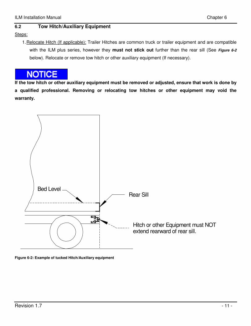
1. Relocate Hitch (If applicable): Trailer Hitches are common truck or trailer equipment and are compatible
with the ILM plus series, however they must not stick out further than the rear sill (See Figure 6-2
below). Relocate or remove tow hitch or other auxiliary equipment (If necessary).
If the tow hitch or other auxiliary equipment must be removed or adjusted, ensure that work is done by
a qualified professional. Removing or relocating tow hitches or other equipment may void the
warranty.
Bed LevelRear Sill
Hitch or other Equipment must NOTextend rearward of rear sill.
Figure 6-2: Example of tucked Hitch/Auxiliary equipment

ILM Installation Manual Chapter 6
Revision 1.7 - 12 -
Corner Post
Sub-Frame
Liftgate
Corner Post
Sub-Frame Flat Bar
Liftgate
6.3 Flush the Sill (Sub- Framing)
Steps:
1. Flush the sill: Some trucks or trailers may have configurations with irregular shaped sills. Liftgate
mounting surface may NOT be flush with corner post. Some sills may be inset or have door gutters.
All these situations are remedied with a process called sub-framing and/or flushing the sill.
Sub-framing is done one of two ways; Sub-frame can be built up using correct size 3/16” or greater wall tubing before liftgate is mounted. Or, the liftgate can be mounted into position and sub-frame can be built as liftgate is installed with 3/16” or greater flat bar. In either case, liftgate installation weld procedure does not change. These examples are show below. Flushing floor or filling gap between Sill and liftgate can be done up to 6” without cross supports. Use ¼” or greater flat bar or diamond plate to span gap. Original width of the truck frame should be matched as close as possible.
Bed Level Corner Stiffener
Light Box
Corner Post
Liftgate Mounting Surface
Liftgate Platform Surface
Gap between Sill and Liftgate
Figure 6-3: Diagram of Rear Sill (Above)
Tubing sub-frame Flat Bar sub-frame
Figure 6-4: Top View of Sub-
Frame examples

ILM Installation Manual Chapter 6
Revision 1.7 - 13 -
2. Flat Bar Posts (if necessary): Corner stiffeners are common and should NOT be removed. It is
recommended to “flat bar” with same thickness as stiffeners, typically ¼” to 3/8” thick x 3” wide. Liftgate
Installation weld procedure is the same.
Corner Stiffener
Corner Stiffener
Flat Bar
Flat Bar
Flat Bar
Figure 6-5: Flat Bar placed to fill the gap between mounting surface and liftgate

ILM Installation Manual Chapter 6
Revision 1.7 - 14 -
6.4 Support Body
Side supports can be used to strengthen body.
Steps:
1. Add body supports (If necessary): If extra support is required, add support bars. Refer to Strength
Requirements section 5.3.
Flatbed installation may use similar arrangement with 3/16” x 4” x 4”min. rectangular tubing for corner
post and 3” channels for support bar.
72"
Approx. 60"
Support Bar1/4" x 3" Min. Flat Bar
1/4" x 100% weld each end
Sub-plate for alum side rails1/4" x 4" Min. bolted either side
of body cross member.
Figure 6-6: Support Bar Diagram

ILM Installation Manual Chapter 6
Revision 1.7 - 15 -
Tack Weld Or ClampTo Rear Sill
Tack or clamp channel to hold in place
Do NOT weld along vertical posts on van install.
3/16" welds for bed extension
Floor at Back & Front EdgeBed Extension Must Be Flush With
Channel or Equiv.
Channel extends 5" beyond end of bed extension for platform installation.
5"
6.5 Add Alignment Bars (Optional)
The liftgate should be installed level to the rear sill. One method of doing this is to weld two alignment bars to
the rear sill. This acts as a “stop” as the liftgate is hoisted up. This step should be done before the liftgate is
raised to the vehicle. Other methods may also be used.
Steps:
1. Weld Alignment Bars: Weld two (2) supports to the sill of the truck (See Figure 6-7 below). This will
help ensure even alignment between liftgate crossbeam and body sill. Use 3” angle or channel
approximately 10” long.
Figure 6-7: Alignment Bar Diagram
ILM Installation Manual Chapter 7
Revision 1.7 - 16 -
7 Liftgate Preparation
Step 3 is best done while the liftgate is suspended. It is recommended to use a forklift or crane to hoist the liftgate. (Reference the “Positioning Liftgate” section on next page). Never position any portion of body under liftgate.
Steps:
1. Remove Shipping Ties: Remove shipping ties from all electrical harnesses and secure so they do NOT
interfere with liftgate positioning or welding processes.
2. Mark Centers: Mark the center of the liftgate as well as the rear sill as reference points for alignment in
later steps. An Alternative method for centering the liftgate is explained on the next page. Reference
Step 5 in the Gate Installation section on page 17.
3. Remove Lower shipping feet: Lower shipping feet may have to be removed for installation on some deep
sills.
ILM Installation Manual Chapter 8
Revision 1.7 - 17 -
8 Gate Installation
8.1 Hoisting the Liftgate
Before positioning the liftgate; consider when measuring and centering the liftgate that the truck or
trailer may NOT be square or parallel. Special care must be taken to ensure that the liftgate is square
and parallel before welding. Always disconnect the battery from the truck/trailer before welding to
avoid damage to the electrical system.
Steps:
1. Level Truck: Truck should be on level and even ground. Uneven ground will give misleading
measurements and can cause body twist or racking.
2. Make sure the liftgate is properly secured: Take a moment to check that the liftgate is attached safely to
the lifting device. To keep the liftgate from sliding back towards the forklift use 4”x 4” x 24” wood
spacers (See Figure 8-1 on next page). This will help force the top of the liftgate tight against body for
welding.
4. Fit Liftgate Against Truck: Hoist the Liftgate; preferred method for lifting liftgate is with a forklift. Position
forks to widest point and lift from center. Be sure not to damage liftgate while lifting by applying too
much force on the alignment bars.
5. Center Liftgate:
Method A: Align the liftgate so that it is centered on the truck. Use the center marks as a
reference for this step. 12” or larger “C” or “F” style clamps can be used to coach or hold the liftgate in
position.
Method B: An Alternative method for centering the liftgate is to measure side clearances from
the outside of the liftgate to the outside of the body. (Centerline marked on sill is NOT easily visible, but
can still be used as a reference.)
6. Verify Position: Confirm all mounting dimensions are correct, double check that floor and threshold
extension are flush. Securely clamp the liftgate to the truck/trailer and do not remove the lifting device
yet.
Never remove lifting device until liftgate is fully welded.

ILM Installation Manual Chapter 8
Revision 1.7 - 18 -
Floor/Bed Height
90°
Forklift Not Shown
Support Channel
Forks
4x4x24 Wood Block
Figure 8-1: Liftgate hoisted into position with forklift

ILM Installation Manual Chapter 8
Revision 1.7 - 19 -
8.2 Check Liftgate Dimensions
Steps:
1. Check Dimensions: Inspect liftgate to be certain it is square and parallel. Use a 3 ft carpenters square.
Verify columns are 90 degrees to sill or body.
2. Use “Dim A” and “Dim B” to verify columns are parallel.
3. Use “Dim C” and “Dim D” to verify columns are square.
DO NOT WELD until all dimensions are checked and rechecked after each positioning adjustment.
Dim "A"
Dim "B"
Dim "C"Dim "D"
Figure 8-2: Liftgate Dimensions

ILM Installation Manual Chapter 8
Revision 1.7 - 20 -
8.3 Welding Liftgate
Before Welding:
• Do not position hands, feet, or any other body part underneath the liftgate until installation is complete.
• Disconnect all battery cables before welding to prevent possible damage to the trucks electrical system.
• Do not remove clamps or lifting device until the gate is welded.
• Never weld at the location of the slide pads, which are connected to the runner (See figure below)
Side View
Slid
e P
ads
Runner
Towards Front of truck
Rail Cap
7"
27-3/4"
Mount Plate
Figure 8-3: Liftgate Welding Areas, Side View. Liftgate shown in shipping position.
Steps:
1. Outside Welds: If your gate came equipped with Rail Caps, remove them before welding. Using 3/16” x
2” welds, place one weld ½” from the top of each column on the outside and place one weld at the
bottom of each mount plate. Never weld at the same location as the slide pads. (See Figure 8-3
above)
STOP and recheck all mounting dimensions.
Step 1
Welds

ILM Installation Manual Chapter 8
Revision 1.7 - 21 -
2. Open and Lower Liftgate: After the gate has been properly welded in step 1, supply temporary power to
the liftgate using a 12-Volt battery source. Open the platform and then lower the liftgate to the ground.
Once opened and lowered, disconnect the temporary battery. This will allow space to finish welding,
and move the slide pads out of the way of heat from welding.
3. Inside Column Welds: Weld inside of columns using 3/16” x 2” welds in 4 places evenly spaced top to
bottom.
4. Inside Floor Welds: Weld inside of floor using 3/16” x 2” welds in 5 places evenly spaced left to right.
5. Final Outside Welds: Finish welding outside of columns using 3/16” x 2” welds in 5 places evenly spaced.
6. Attach End Caps: Once the liftgate has cooled to touch, reattach the end caps to the top of the columns
(if applicable)
Outside Column 3/16” x 2” weld 6 places as shown.
Inside Column 3/16” x 2” weld 4 places as shown.
Inside Floor 3/16” x 2” weld 5 places as shown.
On “Power Closing” liftgates, inside hose guard must be removed for proper welding of inside of column. Take special care not to burn hose.
On each side place (2) of the Outside Column welds at the upper and lower end of the mount plate. Take precautionary measures to ensure that the mount plates do not toe-out due to welding.
Figure 8-4: Weld Locations

ILM Installation Manual Chapter 8
Revision 1.7 - 22 -
8.4 Column Modification
If the columns are too long, they will need to be shortened to provide adequate ground clearance.
Remember, the maximum distance from the ground to the bottom of the track is 18”.
Steps:
1. Measure Height: With the liftgate in its highest position, measure from level ground to bottom of the
column. Consider ride height at the vehicle’s max load capacity, as well as dry unloaded ride height.
2. Mark Cut Line: Mark where the columns should be cut.
3. Cut Column: Cut the excess length of the column. Deburr after cutting by grinding the inside and outside
edges smooth. Chamfer the inside edge at 45ox1/8”.
Track
MaximumGround Clearence 18"
Add diagonal bracingto column if desired
Optional: If desired, diagonal bracing can be connected to the rail and underside of the truck/trailer body
for added strength or aesthetic purposes as shown in the figure above. Diagonal supports are not
required. Follow step 4 for instructions.
4. Add Diagonal Support (Optional): If desired cut an appropriate length of metal at 450 on both ends. If
necessary, use ¼” thick plate to bridge the gap between two body sills. The Lifting bar from the
liftgate‘s shipping stand can be cut and used for bracing.
Deburr edges from track that have been cut with a 45ox 1/8” inner chamfer.
Do not put grease or penetrating lubricants on rails or runners

ILM Installation Manual Chapter 8
Revision 1.7 - 23 -
Upper Mounting
Position (4 long rivets)
Lower Mounting
Position (4 short rivets)
Sleeve (3 short rivets)
Figure 8-6: Bracket Mounting
8.5 Installation of bracket for Control Unit
Steps:
Disconnect liftgate power cable at battery. Liftgate should be in stored position.
1. Mount Bracket for Control Unit: Mount the bracket control unit at liftgate column (curb side) with four
rivets. For trucks with a bed height of 46” to 54” use the lower mounting position and short rivets. For
trucks with bed height of 46” of less use the upper mounting position and long rivets (see Figure 8-6
below). Install rivets with a rivet gun.
2. Install Control Unit: Install the control unit to the bracket. The cable should face towards the ground.
Mount with a bolt at the bracket.
3. Install Cable Sleeve: Install the cable sleeve at the column with short rivets. For higher bracket position,
use three upper holes provided. For lower bracket position, use the lower three holes (see Figure 8-6
below).
4. Connect Battery: Connect the battery cable.
5. Operate: Briefly operate the liftgate to check functions.

ILM Installation Manual Chapter 9
Revision 1.7 - 24 -
150 AMP Resetable Breaker
RES
ET
Test
9 Electrical Installation
When performing electrical installation, please be certain to install and secure everything in a
way where it is not subject to damage from moving parts, sharp edges, exhaust systems, fuel
lines, etc. It is recommended to use dielectric grease on all electrical connections.
9.1 Main Power Connections
Steps:
1. Verify Equipment: Check for 2 gauge ground cable or heavier connecting truck batteries to chassis. If
NOT supplied by the manufacturer, one will need to be installed. Be sure to grind off paint or under
coat and seal.
2. Route Battery Cable: Route battery cable to truck batteries and secure with clips and ties supplied.
Recommended Cable Routing for Trucks
Body Stringer
Sub Wood
Truck Frame
Cable Staples
Route Cables to OUTSIDE of U-Bolts
For trailer installation refer to trailermanufacturers recommended routing
Battery Cable
2 Wire Control Box Power Cable
4-Wire Control Cable
Figure 9-1: Recommended cable routing for trucks
Never secure cable in a way where it can make contact with other wiring, brake fuel or airlines etc. or get pinched against other objects.
3. Install Circuit Breaker: Install 150 amp circuit breaker at battery location and use 12” cable to connect to
positive terminal.
Basic wiring diagrams are provided on the following pages.

ILM Installation Manual Chapter 9
Revision 1.7 - 25 -
1/4
/10
Jones
25 F
t. x
4 G
a. B
attery
Cable
Power - Red
Starter - Green
Lower - Black
Low
er
Sole
noid
Gro
und -
Low
er
Sole
noid
- B
lack
Low
er
Sole
noid
- B
lack S
tart
er
Sole
noid
4 G
a. B
attery
Cable
Ele
ctric
Moto
r
ILM
Wirin
g S
chem
atic
1"=
1"
INTERLIFT, Inc.
15939 Piuma Ave.
Cerritos, CA 90703
888-774-5844
12"
x 4 g
a. B
attery
Cable
To T
ruck
Battery
150 a
mp
Circu
it B
reake
r
10 A Fuse
Manual C
losi
ng
Pow
er
- B
lack
70-0
709-9
02
Main
Lift
gate
2-B
utton C
ontr
ol
Power - Brown
Load - Blue
Cab Shut Off SwitchUnplug Red and Black wires.Plug Brown & Black wires.Plug Blue & Red wires.
08-6
90 7
0-0
0 0
9-0
4
70-0
709-9
04
Rais
e
Low
er
Pow
er
- R
ed
Low
er
- B
lack
Sta
rter
- G
reen
Seal w
ith
Heat S
hrink
Seal w
ith
Heat S
hrink
EC
N-M
0133 -
9/1
7/1
2 -
Rev
"D"
Add 3
-wire c
ab s
witc
h a
nd h
arn
ess
.
EC
N1927 -
6/2
9/1
1 -
Rev
"C"
Change r
em
ote
sw
itch w
ire c
olo
rs.
EC
N1873 -
5/2
0/1
1 -
Rev
"B"
Added M
BB
Toggle
Sw
itch O
ptio
n
EC
N1656 -
1/6
/10 -
Rev
"A"
Rele
ase
d to P
roduct
ion
Rais
e
Low
er
70-0
709-9
03
Optio
nal I
nsi
de
Coil
Cord
Rem
ote
2-B
utton C
ontr
ol
Pow
er
- W
hite
#4
Low
er
- B
lack
#6
Rais
e -
Gre
en #
5
MB
B
Pow
er
- B
lack
#4
Low
er
- B
lack
#6
Rais
e -
Bla
ck #
5P-2
004565
Optio
nal I
nsi
de
Hard
Mount T
oggle
Contr
ol
70-0
709-9
06
Rem
ote
Harn
ess
Import
ant N
ote
:A
ll co
nnect
ors
are
to b
e in
sula
ted a
nd w
eath
er
seale
d.
Ground - Yellow/Green
2025982 C
ab S
witc
h H
arn
ess
Cab C
ut-
Off s
witc
h70-1
012-0
02
Pow
er
Load
Gro
und
Gro
und -
Yello
w/G
reen
Gro
und
Stu
d
9.2 Basic Wiring (Manual Closing)
Figure 9-2: Basic Wiring Diagram (Manual Closing Liftgate)

ILM Installation Manual Chapter 9
Revision 1.7 - 26 -
12/2
8/0
9Jo
nes
25 F
t. x
4 G
a. B
attery
Cable
Power - Red
Raise - Green
Closer - White
Lower - Black
Low
er
Sole
noid
Gro
und -
Clo
ser
Sole
noid
- B
lack
Gro
und -
Low
er S
ole
noid
- B
lack
Low
er
Sole
noid
- B
lack
Clo
sing S
ole
noid
Sta
rter
Sole
noid
4 G
a. B
attery
Cable
Ele
ctric
Moto
r
ILM
Wirin
g S
chem
atic
1"=
1"
INTERLIFT, Inc.
15939 Piuma Ave.
Cerritos, CA 90703
888-774-5844
12"
x 4 g
a. B
attery
Cable
To T
ruck
Battery
150 a
mp
Circu
it B
reake
r
Rais
e
Shift
Low
er
10 A Fuse
Pow
er
Clo
sing
Low
er
Sole
noid
- B
lack
Pow
er -
Bla
ck
70-0
709-9
01
Main
Lift
gate
3-B
utton C
ontrol
Rais
e
Low
er
70-0
709-9
03
Optio
nal I
nsi
de
Coil
Cord
Rem
ote
2-B
utton C
ontr
ol
Pow
er -
White
#4
Low
er
- B
lack
#6
Rais
e -
Gre
en #
5
08-6
90 7
0-0
0 0
9-0
5
70-0
709-9
05
Pow
er -
Red
Low
er
- B
lack
Rais
e-
Gre
en
Seal w
ithH
eat S
hrink
Seal w
ithH
eat S
hrink
EC
N-M
0133 -
9/1
7/1
2 -
Rev
"D"
Add 3
-wire c
ab s
witc
h a
nd h
arn
ess
.
EC
N1927 -
6/2
9/1
1 -
Rev
"C"
Changed r
em
ote
sw
itch w
ire c
olo
rs.
EC
N1873 -
5/2
0/1
1 -
Rev
"B"
Added M
BB
Toggle
Sw
itch O
ptio
n
EC
N1656 -
1/6
/10 -
Rev
"A"
Rele
ase
d to P
roduct
ion
MB
B
Pow
er -
Bla
ck #
4
Low
er -
Bla
ck #
6
Rais
e -
Bla
ck #
5P-2
004565
Optio
nal I
nsi
de
Hard
Mount To
ggle
Contr
ol
70-0
709-9
06
Rem
ote
Harn
ess
Import
ant N
ote
:A
ll co
nnect
ors
are
to b
e in
sula
ted a
nd w
eath
er se
ale
d.
Power - Brown
Load - Blue
Cab Shut Off SwitchUnplug Red and Black wires.Plug Brown & Black wires.Plug Blue & Red wires.
Ground - Yellow/Green
2025982 C
ab S
witc
h H
arn
ess
Cab C
ut-O
ff sw
itch
70-1
012-0
02
Pow
er
Load
Gro
und
Gro
und - Y
ello
w/G
reen
Gro
und
Stu
d
9.3 Basic Wiring (Power Closing Liftgate)
Figure 9-3: Basic Wiring Diagram (Power down

ILM Installation Manual Chapter 10
Revision 1.7 - 27 -
10 Lubrication
When kept properly lubricated, the PALFINGER ILM liftgate will ensure long lasting usage. Therefore, the liftgate pivot points should be lubricated at the same time as the truck/trailer. Lubricate more frequently if the lift gate is heavily used or whenever the pivot points appear to be dry. Average ILM plus use is considered 15 cycles per day or 1200 cycles per quarter.
DO NOT grease or apply penetrating oil to the “Slider Bearings” or “Columns” or “Runners”, as this will VOID your WARRANTY on the slide bearings. There are 4 grease fittings to maintain. Grease pivot points as shown in Figure 10-1 below. DO NOT use lubrication grease to lubricate the rails. Manual Closing Gates: Use a light penetrating oil on closing aids; left & right side, upper & lower gas spring mounting points. Power Closing: Grease upper & lower pivot mounting points. Under normal use and conditions, the lifting roller chain will require minimal lubrication or maintenance as it is impregnated with good quality grease and only makes contact with Polymer sprockets. In extreme environments, should roller chain show signs of drying or rust, lubricate with a good quality penetrating type “chain lube”.

ILM Installation Manual Chapter 10
Revision 1.7 - 28 -
Lubrication Locations: All bearing points must be lubricated in accordance with the maintenance interval.
Lubricating grease nipple (1 on each side) Oil level in the power pack tank (see marking inside of power pack reservoir)
Platform hinges and optional Cart Stops (use a penetrating oil/spray for lubrication)
Figure 10-1: Grease Points, General View:
Do not put grease or penetrating oil on rails or runners. This will void warranty

ILM Installation Manual Chapter 11
Revision 1.7 - 29 -
11 Cycle Test and Final Inspection
11.1 Cycle Test and Bleed the hydraulic system.
Improper use of the liftgate may result in serious injury. DO NOT operate this liftgate without
being properly instructed and fully understanding the Owner’s manual. Platform may crush or
pinch. Make certain area around liftgate is clear during all times of operation.
No bleeding of hydraulic system is required. System is a self-bleeding system and is pre-bled
from the factory. Test steps a minimum of five (5) times each to ensure NO unusual noises or
movements are found. This will confirm all controls work correctly and hydraulic system is
completely bled of air.
POWER CLOSING Operating Instructions
Switch Operations for “Power Closing”
• “UP” switch raises platform from ground to bed.
• “DOWN” switch lowers platform from bed to ground.
• “SHIFT” + “UP” closes platform from loading position to stored position.
• “SHIFT” + “DOWN” opens platform from stored position to loading position.
Storage and Transit Position “Power Closing”
• Platform is closed and stored UP tight into the storage latch with hydraulic power.
• Pad lock is used on safety latch to prevent unauthorized use.
• Never release platform on to safety latch. This latch is for EMERGENCY situations ONLY.
Platform from Stored Position to Loading position “Power Closing”
• Be certain all pinch points and areas around platform are clear before operating liftgate.
• Hold safety latch to the open position and push “DOWN” button until platform clears storage latching
system.
• With platform clear of latching system, hold “SHIFT” button & push “DOWN” button to open platform to
loading position.
Platform from Loading Position to Stored Position “Power Closing”
• Be certain all pinch points and areas around platform are clear before operating liftgate.

ILM Installation Manual Chapter 11
Revision 1.7 - 30 -
• With platform in the loading position, hold “SHIFT” button & push “UP” button until platform touches
striker pads.
• With platform folded up and touching striker pads, push “UP” button until platform is powered tight into
storage latch.
• Never release platform on to safety latch. This latch is for EMERGENCY situations ONLY.
MANUAL CLOSING Operating Instructions
Switch Operations “Manual Closing”
• “UP” switch raises platform from ground to bed.
• “DOWN” switch lowers platform from bed to ground.
Storage and Transit Position “Manual Closing”
• Platform is closed and stored tight into the storage latch with hydraulic power.
• Pad lock is used on safety latch to prevent unauthorized use.
• Never release platform on to safety latch. This latch is for EMERGENCY situations ONLY.
Platform from Stored Position to Loading position “Manual Closing”
• Be certain all pinch points and areas around platform are clear before operating liftgate.
• Hold safety latch to the open position and push “DOWN” button until platform clears storage latching
system.
• With platform clear of latching system, and positioned to firmly grasp ramp end, pull platform towards
ground.
Platform from Loading Position to Stored Position “Manual Closing”
• Be certain all pinch points and areas around platform are clear before operating liftgate.
• With platform in the loading position, and positioned just above knee height, firmly grasp ramp end and
pull up closing until platform touches striker pads.
• With platform folded up and touching striker pads, push “UP” button until platform is powered tight into
storage latch.
• Never release platform on to safety latch. This latch is for EMERGENCY situations ONLY.

ILM Installation Manual Chapter 11
Revision 1.7 - 31 -
11.2 Decal Placement and inspection
For operator’s safety, all decals appearing in “Decal Kit” must be placed visibly on control side of liftgate to be read by operator. This is typically a combination of decals on the liftgate and truck body. Please make sure to place the maximum capacity decal (C) on driver and curb side. (A) 1 ATG-OPERILM MC/PC - Operating Instructions
(B) 1 ATG- SWILM MC/PC - Main Operation Switch
(C) 2 ATG-XXXX - Max. Capacity (please check the serial number plate to find out your specific capacity)
(D) 1 ATG-URGWA - Urgent warning: Elevating gate instructions
(E) 2 ATG-WLH - Warning: liftgate can crush
(F) 2 ATG-PLAT - Caution: Always stand clear of platform area
(G) 1 ATG-RESET - Circuit Breaker Protection
(H) 1 ATG-BKR - Circuit Breaker Reset (must be located at the circuit breaker)
(J) 1 ATG-CAB - Liftgate Shut-Off (must be placed next to the Shut-Off Switch)
(K) 1 ATG-UD - Toggle Decal (only if applicable)
(L) 1 ATG-ILMSTORAGE – Storage Latch
(M) 1 Conspicuity Tape (If Applicable)
(N) 2 85-0713-100- Do Not Grease
Decal A
Version A
Decal – B
Version B
Decal - C
Decal - G
Decal - H
Decal - J
Decal - F
Decal - L
Decal – B
Version A
Decal – A Version B
Decal - K
Decal - E
Decal - D
Decal - M Decal - N

ILM Installation Manual Chapter 11
Revision 1.7 - 32 -
Decal B
Decal C (at both sides)
Decal A
Decal G
Decal D
Decal E (at both sides)
Decal L
Decal F (at both sides)
Figure 11-1: Decal Placement Guideline
Decal H - By circuit breaker at batteries Decal J - In the cab or at On - Off at rear
Decal N (at both sides)
You may obtain free replacement decals by calling PALFINGER Liftgates at 888-774-5844. Please have
your liftgate model # and serial # ready.

ILM Installation Manual Chapter 11
Revision 1.7 - 33 -
It is the installer’s responsibility to determine the proper application of the Conspicuity tape, and to ensure that the vehicle or trailer meets DOT and federal lighting regulations. The following diagram is a guideline for placement on trailers over 80” wide and GVWR of 10,000 Lbs or more. This document is not intended to replace published agency regulations, and it is strongly recommended that the installer refer to the Code of Federal Regulations (CFR) which can be viewed at http://ECFR.gpoaccess.gov.
H Dimension: 15”< H <60” from ground to center of tape
Requirement 3: Red/white reflective tape applied across the entire width of the rear underride protection device. Note: Not required if no underride protection is equipped
Requirement 2: On each corner: Two 12” long white reflective pieces, place adjacently to one another as close to the upper corner of the trailer as possible
Requirement 1: Red/white reflective tape applied across the entire width of the trailer placed at an appropriate height H from the ground
H

ILM Installation Manual Chapter 11
Revision 1.7 - 34 -
11.3 Final Inspection Check List
Liftgate failure or malfunction could result in property damage, personal injury or death if you fail to
check each of the following items listed. DO NOT USE the liftgate if any of the following points are
NOT verified and checked.
Installation is NOT complete and all WARRANTIES are VOID if you have not checked and verified all items listed on this inspection sheet. Inspection sheet is to be filed at the facility where liftgate was installed. Structural Inspection
� Lifting bar and shipping feet are removed from the liftgate.
� All welds are 100% complete per this manual.
� All nuts, bolts, mounting hardware, pins, chain anchors are tight.
� All mounting dimensions are correct and liftgate is square and parallel per this manual. Hydraulic Inspection
� Pump reservoir is filled to 1.5" from top when platform is opened and on the ground.
� Hydraulic components and connections do not leak. (Should be checked after unit is hydraulically locked for five (5) minutes.)
� All hydraulic lines are secured with cable ties, hoses clamps, or other fasteners. Electrical Inspection
� Battery cable(s) attached and clamped tight and dielectric grease is used to seal all connections. � All electrical lines are secured with cable ties, hoses clamps, or other fasteners. � Circuit Breakers installed and wired per instructions. � Lights wired properly and operate per DOT, State, and Federal requirements. Operational Inspection
� All decals are in place and legible per instructions. � All pivot points are lubricated per instructions. � Platform secures properly in its stowed position latches. � Platform powers UP and locks hydraulically in latches.
� Platform travels up and down smoothly and freely, without any hesitation or unusual noises.
� Platform is level with the floor of the vehicle when raised completely. � Platform rests on the ground evenly when lowered completely. � Platform opens and closes properly and at correct speed. (2 to 4 inches per second) � The liftgate serial number and model number are documented on the inside of the front cover of the Owners Manual, in the space provided. � Owners Manual is in the vehicle's glove box. � Supervisor has demonstrated the instructions in the Owners Manual to the customer/driver upon delivery.
� Gate is properly lubricated as explained in chapter 10, Lubrication. Inspection Information: Name (please print): ____________________________________________________________ Completed by: ________________________________________________________________ (signature) Title: ______________________________________________ Date: _____________________