Embed Size (px)
Citation preview

IM3034 02/2010
Rev. 0
LINC FEED 45S
OPERATOR’S MANUAL INSTRUKCJA OBSŁUGI
LINCOLN ELECTRIC BESTER ul. Jana III Sobieskiego 19A, 58-260 Bielawa, Poland
www.lincolnelectric.eu
2
Declaration of conformity
LINCOLN ELECTRIC BESTER
Declares that the welding machine:
LINC FEED 45S
conforms to the following directives:
2006/95/CEE, 2004/108/CEE
and has been designed in compliance with the following standards:
EN 60974-1, EN60974-5, EN 60974-10
(2010)
Paweł Lipi�ski
Operations Director LINCOLN ELECTRIC BESTER, ul. Jana III Sobieskiego 19A, 58-260 Bielawa, Poland
3
Deklaracja zgodno�ci
LINCOLN ELECTRIC BESTER
Deklaruje, �e spawalnicze �ródło energii:
LINC FEED 45S
spełnia nast�puj�ce wytyczne:
2006/95/CEE, 2004/108/CEE
i �e zostało zaprojektowane zgodnie z wymaganiami nast�puj�cych norm:
EN 60974-1, EN60974-5, EN 60974-10
(2010)
Paweł Lipi�ski
Operations Director LINCOLN ELECTRIC BESTER, ul. Jana III Sobieskiego 19A, 58-260 Bielawa, Poland

4
12/05
THANKS! For having choosen the QUALITY of the Lincoln Electric products. • Please Examine Package and Equipment for Damage. Claims for material damaged in shipment must be notified immediately to the
dealer. • For future reference record in the table below your equipment identification information. Model Name, Code & Serial Number can be
found on the machine rating plate. GRAZIE! Per aver scelto la QUALITÀ dei prodotti Lincoln Electric. • Esamini Imballo ed Equipaggiamento per rilevare eventuali danneggiamenti. Le richieste per materiali danneggiati dal trasporto devono
essere immediatamente notificate al rivenditore. • Per ogni futuro riferimento, compilare la tabella sottostante con le informazioni di identificazione equipaggiamento. Modello, Codice
(Code) e Matricola (Serial Number) sono reperibili sulla targa dati della macchina. VIELEN DANK! Dass Sie sich für ein QUALITÄTSPRODUKT von Lincoln Electric entschieden haben. • Bitte überprüfen Sie die Verpackung und den Inhalt auf Beschädigungen. Transportschäden müssen sofort dem Händler gemeldet
werden. • Damit Sie Ihre Gerätedaten im Bedarfsfall schnell zur Hand haben, tragen Sie diese in die untenstehende Tabelle ein.
Typenbezeichnung, Code- und Seriennummer finden Sie auf dem Typenschild Ihres Gerätes. GRACIAS! Por haber escogido los productos de CALIDAD Lincoln Electric. • Por favor, examine que el embalaje y el equipo no tengan daños. La reclamación del material dañado en el transporte debe ser
notificada inmediatamente al proveedor. • Para un futuro, a continuación encontrará la información que identifica a su equipo. Modelo, Code y Número de Serie los cuales pueden
ser localizados en la placa de características de su equipo. MERCI! Pour avoir choisi la QUALITÉ Lincoln Electric. • Vérifiez que ni l’équipement ni son emballage ne sont endommagés. Toute réclamation pour matériel endommagé doit être
immédiatement notifiée à votre revendeur. • Notez ci-dessous toutes les informations nécessaires à l’identification de votre équipement. Le nom du Modèle ainsi que les numéros de
Code et Série figurent sur la plaque signalétique de la machine. TAKK! For at du har valgt et KVALITETSPRODUKT fra Lincoln Electric. • Kontroller emballsjen og produktet for feil eller skader. Eventuelle feil eller transportskader må umiddelbart rapporteres dit du har kjøpt
din maskin. • For fremtidig referanse og for garantier og service, fyll ut den tekniske informasjonen nedenfor i dette avsnittet. Modell navn, Kode &
Serie nummer finner du på den tekniske platen på maskinen. BEDANKT! Dat u gekozen heeft voor de KWALITEITSPRODUCTEN van Lincoln Electric. • Controleert u de verpakking en apparatuur op beschadiging. Claims over transportschade moeten direct aan de dealer of aan Lincoln
electric gemeld worden. • Voor referentie in de toekomst is het verstandig hieronder u machinegegevens over te nemen. Model Naam, Code & Serienummer staan
op het typeplaatje van de machine. TACK! För att ni har valt en KVALITETSPRODUKT från Lincoln Electric. • Vänligen kontrollera förpackning och utrustning m.a.p. skador. Transportskador måste omedelbart anmälas till återförsäljaren eller
transportören. • Notera informationen om er utrustnings identitet i tabellen nedan. Modellbeteckning, code- och serienummer hittar ni på maskinens
märkplåt. DZI�KUJEMY! Za docenienie JASKO�CI produktów Lincoln Electric. • Prosz� sprawdzi� czy opakownie i sprz�t nie s� uszkodzone. Reklamacje uszkodze� powstałych podczas transportu musz� by�
natychmiast zgłoszone do dostawcy (dystrybutora). • Dla ułatwienia prosimy o zapisanie na tej stronie danych identyfikacyjnych wyrobów. Nazwa modelu, Kod i Numer Seryjny, które mo�ecie
Pa�stwo znale�� na tabliczce znamionowej wyrobu. KIITOS! Kiitos, että olet valinnut Lincoln Electric LAATU tuotteita. • Tarkista pakkaus ja tuotteet vaurioiden varalta. Vaateet mahdollisista kuljetusvaurioista on ilmoitettava välittömästi jälleenmyyjälle. • Tulevaisuutta varten täytä alla oleva lomake laitteen tunnistusta varten. Mallin, Koodin ja Sarjanumeron voit löytää konekilvestä.
Model Name, Modello, Typenbezeichnung, Modelo, Nom du modèle, Modell navn, Model Naam, Modellbeteckning, Nazwa modelu, Mallinimi:
………………...…………………………….………………………………………………………………………………………….. Code & Serial number, Code (codice) e Matricola, Code- und Seriennummer, Code y Número de Serie, Numéros de Code et Série, Kode &
Serie nummer, Code en Serienummer, Code- och Serienummer, Kod i numer Seryjny, Koodi ja Sarjanumero:
………………….……………………………………………….. …………………………………………………….…………….. Date & Where Purchased, Data e Luogo d’acquisto, Kaufdatum und Händler, Fecha y Nombre del Proveedor, Lieu et Date d’acquisition, Kjøps
dato og Sted, Datum en Plaats eerste aankoop, Inköpsdatum och Inköpsställe, Data i Miejsce zakupu, Päiväys ja Ostopaikka:
…………………………………………………………………... ……………………….…………………………………………..

5
ENGLISH INDEX Safety .............................................................................................................................................................................. 6 Installation and Operator Instructions .............................................................................................................................. 7 Electromagnetic Compatibility (EMC) ............................................................................................................................ 16 Technical Specifications ................................................................................................................................................ 16 Spare Parts .................................................................................................................................................................... 28 Electrical Schematic ...................................................................................................................................................... 32 Accessories ................................................................................................................................................................... 33 WEEE …………………………………………………………………… ……………………………………………………….34
SKOROWIDZ POLSKI
Bezpiecze�stwo U�ytkowania ....................................................................................................................................... 17 Instrukcja Instalacji i Eksploatacji .................................................................................................................................. 18 Kompatybilno�� Elektromagnetyczna (EMC) ................................................................................................................. 27 Dane Techniczne ........................................................................................................................................................... 27 Cz��ci Zamienne ........................................................................................................................................................... 28 Schemat Elektryczny ..................................................................................................................................................... 32 Wyposa�enie ................................................................................................................................................................. 33 WEEE ............................................................................................................................................................................ 34
6
Safety
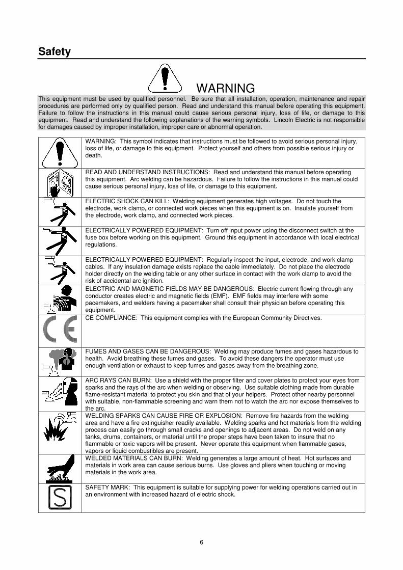
WARNING This equipment must be used by qualified personnel. Be sure that all installation, operation, maintenance and repair procedures are performed only by qualified person. Read and understand this manual before operating this equipment. Failure to follow the instructions in this manual could cause serious personal injury, loss of life, or damage to this equipment. Read and understand the following explanations of the warning symbols. Lincoln Electric is not responsible for damages caused by improper installation, improper care or abnormal operation.
WARNING: This symbol indicates that instructions must be followed to avoid serious personal injury, loss of life, or damage to this equipment. Protect yourself and others from possible serious injury or death.
READ AND UNDERSTAND INSTRUCTIONS: Read and understand this manual before operating this equipment. Arc welding can be hazardous. Failure to follow the instructions in this manual could cause serious personal injury, loss of life, or damage to this equipment.
ELECTRIC SHOCK CAN KILL: Welding equipment generates high voltages. Do not touch the electrode, work clamp, or connected work pieces when this equipment is on. Insulate yourself from the electrode, work clamp, and connected work pieces.
ELECTRICALLY POWERED EQUIPMENT: Turn off input power using the disconnect switch at the fuse box before working on this equipment. Ground this equipment in accordance with local electrical regulations.
ELECTRICALLY POWERED EQUIPMENT: Regularly inspect the input, electrode, and work clamp cables. If any insulation damage exists replace the cable immediately. Do not place the electrode holder directly on the welding table or any other surface in contact with the work clamp to avoid the risk of accidental arc ignition.
ELECTRIC AND MAGNETIC FIELDS MAY BE DANGEROUS: Electric current flowing through any conductor creates electric and magnetic fields (EMF). EMF fields may interfere with some pacemakers, and welders having a pacemaker shall consult their physician before operating this equipment.
CE COMPLIANCE: This equipment complies with the European Community Directives.
FUMES AND GASES CAN BE DANGEROUS: Welding may produce fumes and gases hazardous to health. Avoid breathing these fumes and gases. To avoid these dangers the operator must use enough ventilation or exhaust to keep fumes and gases away from the breathing zone.
ARC RAYS CAN BURN: Use a shield with the proper filter and cover plates to protect your eyes from sparks and the rays of the arc when welding or observing. Use suitable clothing made from durable flame-resistant material to protect you skin and that of your helpers. Protect other nearby personnel with suitable, non-flammable screening and warn them not to watch the arc nor expose themselves to the arc.
WELDING SPARKS CAN CAUSE FIRE OR EXPLOSION: Remove fire hazards from the welding area and have a fire extinguisher readily available. Welding sparks and hot materials from the welding process can easily go through small cracks and openings to adjacent areas. Do not weld on any tanks, drums, containers, or material until the proper steps have been taken to insure that no flammable or toxic vapors will be present. Never operate this equipment when flammable gases, vapors or liquid combustibles are present.
WELDED MATERIALS CAN BURN: Welding generates a large amount of heat. Hot surfaces and materials in work area can cause serious burns. Use gloves and pliers when touching or moving materials in the work area.
SAFETY MARK: This equipment is suitable for supplying power for welding operations carried out in an environment with increased hazard of electric shock.
7
CYLINDER MAY EXPLODE IF DAMAGED: Use only compressed gas cylinders containing the correct shielding gas for the process used and properly operating regulators designed for the gas and pressure used. Always keep cylinders in an upright position securely chained to a fixed support. Do not move or transport gas cylinders with the protection cap removed. Do not allow the electrode, electrode holder, work clamp or any other electrically live part to touch a gas cylinder. Gas cylinders must be located away from areas where they may be subjected to physical damage or the welding process including sparks and heat sources.
Installation and Operator Instructions Read this entire section before installation or operation of the machine. Location and Environment This machine will operate in harsh environments. However, it is important that simple preventative measures are followed to assure long life and reliable operation: • Do not place or operate this machine on a surface
with an incline greater than 15° from horizontal. • Do not use this machine for pipe thawing. • This machine must be located where there is free
circulation of clean air without restrictions for air movement to and from the air vents. Do not cover the machine with paper, cloth or rags when switched on.
• Dirt and dust that can be drawn into the machine should be kept to a minimum.
• This machine has a protection rating of IP23. Keep it dry when possible and do not place it on wet ground or in puddles.
• Locate the machine away from radio controlled machinery. Normal operation may adversely affect the operation of nearby radio controlled machinery, which may result in injury or equipment damage. Read the section on electromagnetic compatibility in this manual.
• Do not operate in areas with an ambient temperature greater than 40°C.
Duty cycle and Overheating The duty cycle of a welding machine is the percentage of time in a 10 minute cycle at which the welder can operate the machine at rated welding current. Example: 60% duty cycle:
Welding for 6 minutes. Break for 4 minutes.
Excessive extension of the duty cycle will cause the thermal protection circuit to activate. The machine is protected from overheating by a thermostat. When the machine is overheated the output of the machine will turn "OFF", and the Thermal Indicator Light (on front panel of wire feeder) will turn "ON". When the machine has cooled to a safe temperature the Thermal Indicator light will go out and the machine may resume normal operation. Note: For safety reasons the machine will not come out of thermal shutdown if the trigger on the welding gun has not been released.
Minutes or decrease
duty cycle
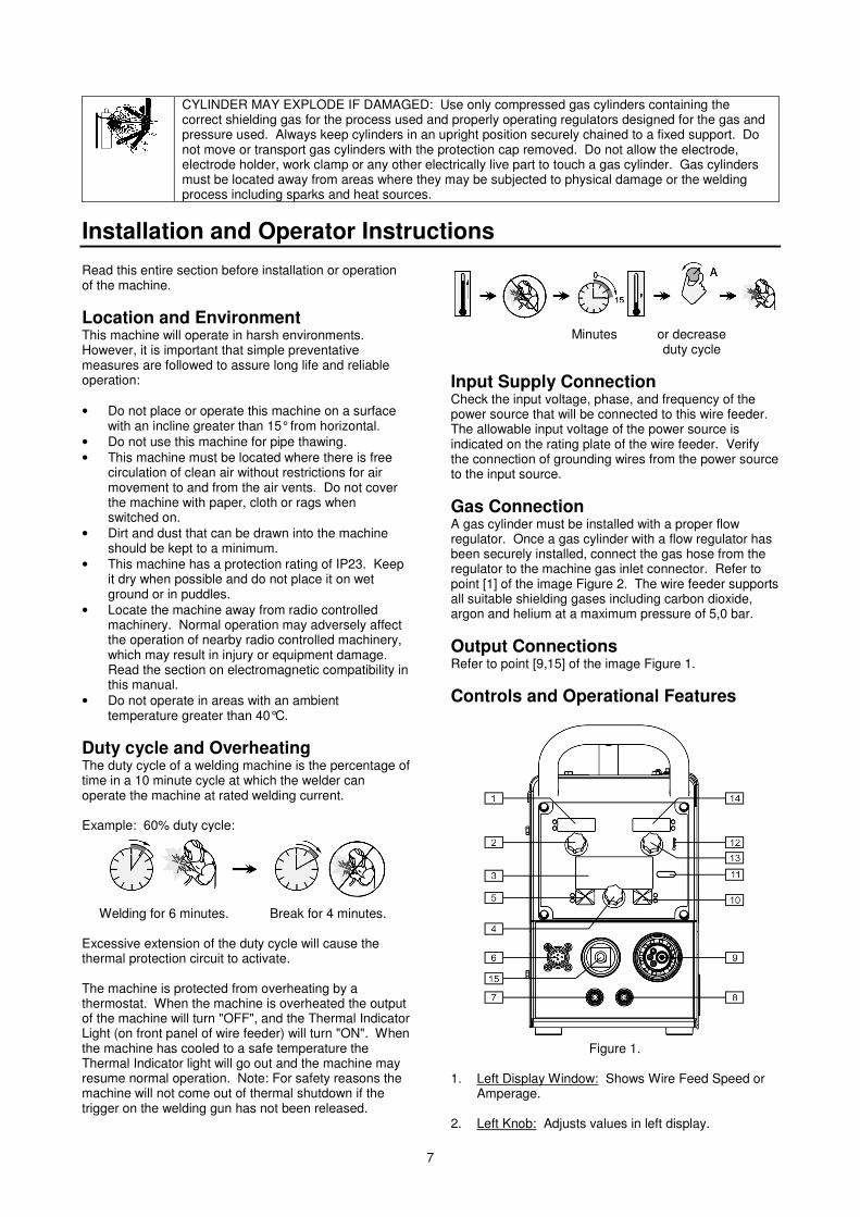
Input Supply Connection Check the input voltage, phase, and frequency of the power source that will be connected to this wire feeder. The allowable input voltage of the power source is indicated on the rating plate of the wire feeder. Verify the connection of grounding wires from the power source to the input source. Gas Connection A gas cylinder must be installed with a proper flow regulator. Once a gas cylinder with a flow regulator has been securely installed, connect the gas hose from the regulator to the machine gas inlet connector. Refer to point [1] of the image Figure 2. The wire feeder supports all suitable shielding gases including carbon dioxide, argon and helium at a maximum pressure of 5,0 bar. Output Connections Refer to point [9,15] of the image Figure 1. Controls and Operational Features
Figure 1.
1. Left Display Window: Shows Wire Feed Speed or
Amperage. 2. Left Knob: Adjusts values in left display.
8
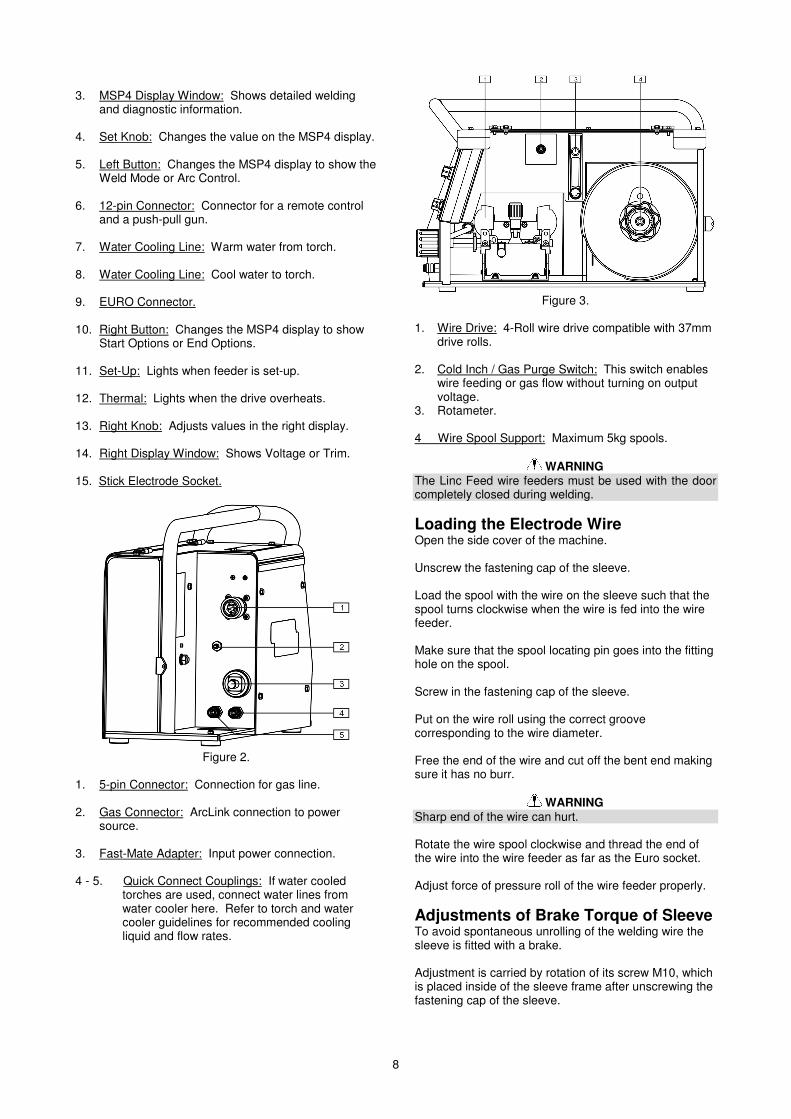
3. MSP4 Display Window: Shows detailed welding
and diagnostic information. 4. Set Knob: Changes the value on the MSP4 display. 5. Left Button: Changes the MSP4 display to show the
Weld Mode or Arc Control. 6. 12-pin Connector: Connector for a remote control
and a push-pull gun. 7. Water Cooling Line: Warm water from torch. 8. Water Cooling Line: Cool water to torch. 9. EURO Connector. 10. Right Button: Changes the MSP4 display to show
Start Options or End Options. 11. Set-Up: Lights when feeder is set-up. 12. Thermal: Lights when the drive overheats. 13. Right Knob: Adjusts values in the right display. 14. Right Display Window: Shows Voltage or Trim. 15. Stick Electrode Socket.
Figure 2.
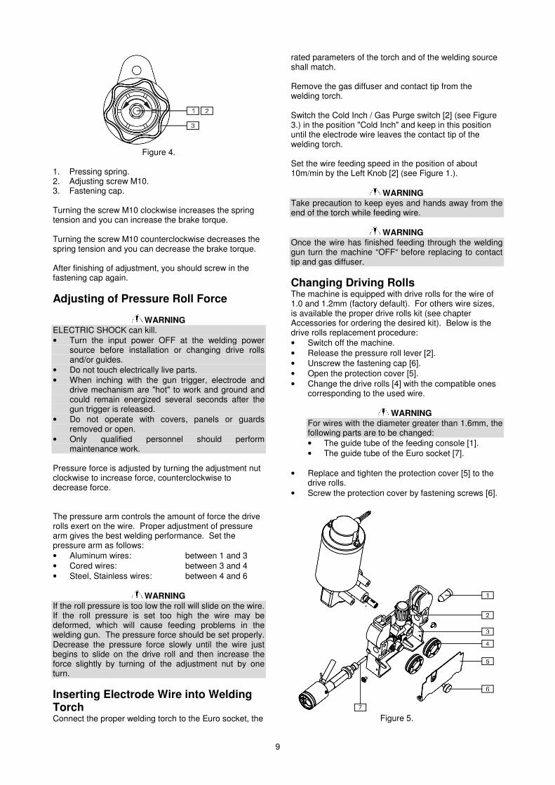
1. 5-pin Connector: Connection for gas line. 2. Gas Connector: ArcLink connection to power
source. 3. Fast-Mate Adapter: Input power connection. 4 - 5. Quick Connect Couplings: If water cooled
torches are used, connect water lines from water cooler here. Refer to torch and water cooler guidelines for recommended cooling liquid and flow rates.
Figure 3.
1. Wire Drive: 4-Roll wire drive compatible with 37mm
drive rolls. 2. Cold Inch / Gas Purge Switch: This switch enables
wire feeding or gas flow without turning on output voltage.
3. Rotameter. 4 Wire Spool Support: Maximum 5kg spools.
WARNING The Linc Feed wire feeders must be used with the door completely closed during welding. Loading the Electrode Wire Open the side cover of the machine. Unscrew the fastening cap of the sleeve. Load the spool with the wire on the sleeve such that the spool turns clockwise when the wire is fed into the wire feeder. Make sure that the spool locating pin goes into the fitting hole on the spool. Screw in the fastening cap of the sleeve. Put on the wire roll using the correct groove corresponding to the wire diameter. Free the end of the wire and cut off the bent end making sure it has no burr.
WARNING Sharp end of the wire can hurt. Rotate the wire spool clockwise and thread the end of the wire into the wire feeder as far as the Euro socket. Adjust force of pressure roll of the wire feeder properly. Adjustments of Brake Torque of Sleeve To avoid spontaneous unrolling of the welding wire the sleeve is fitted with a brake. Adjustment is carried by rotation of its screw M10, which is placed inside of the sleeve frame after unscrewing the fastening cap of the sleeve.
9
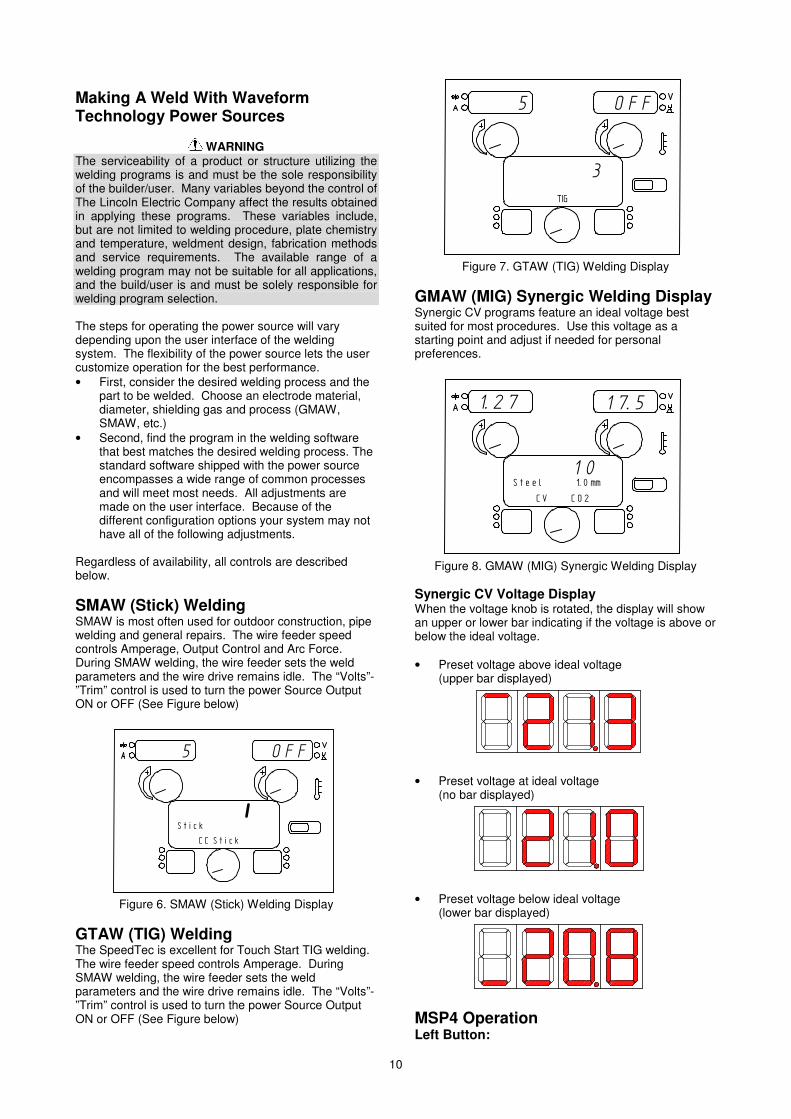
Figure 4.
1. Pressing spring. 2. Adjusting screw M10. 3. Fastening cap. Turning the screw M10 clockwise increases the spring tension and you can increase the brake torque. Turning the screw M10 counterclockwise decreases the spring tension and you can decrease the brake torque. After finishing of adjustment, you should screw in the fastening cap again. Adjusting of Pressure Roll Force
WARNING ELECTRIC SHOCK can kill. • Turn the input power OFF at the welding power
source before installation or changing drive rolls and/or guides.
• Do not touch electrically live parts. • When inching with the gun trigger, electrode and
drive mechanism are "hot" to work and ground and could remain energized several seconds after the gun trigger is released.
• Do not operate with covers, panels or guards removed or open.
• Only qualified personnel should perform maintenance work.
Pressure force is adjusted by turning the adjustment nut clockwise to increase force, counterclockwise to decrease force. The pressure arm controls the amount of force the drive rolls exert on the wire. Proper adjustment of pressure arm gives the best welding performance. Set the pressure arm as follows: • Aluminum wires: between 1 and 3 • Cored wires: between 3 and 4 • Steel, Stainless wires: between 4 and 6
WARNING If the roll pressure is too low the roll will slide on the wire. If the roll pressure is set too high the wire may be deformed, which will cause feeding problems in the welding gun. The pressure force should be set properly. Decrease the pressure force slowly until the wire just begins to slide on the drive roll and then increase the force slightly by turning of the adjustment nut by one turn. Inserting Electrode Wire into Welding Torch Connect the proper welding torch to the Euro socket, the
rated parameters of the torch and of the welding source shall match. Remove the gas diffuser and contact tip from the welding torch. Switch the Cold Inch / Gas Purge switch [2] (see Figure 3.) in the position "Cold Inch" and keep in this position until the electrode wire leaves the contact tip of the welding torch. Set the wire feeding speed in the position of about 10m/min by the Left Knob [2] (see Figure 1.).
WARNING Take precaution to keep eyes and hands away from the end of the torch while feeding wire.
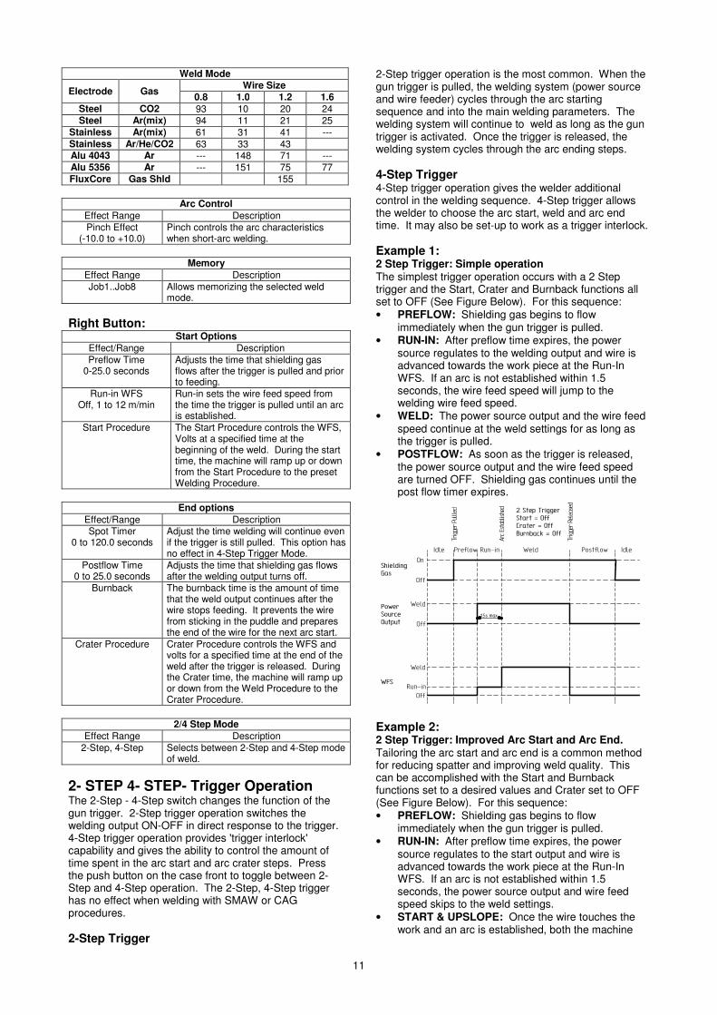
WARNING Once the wire has finished feeding through the welding gun turn the machine “OFF“ before replacing to contact tip and gas diffuser. Changing Driving Rolls The machine is equipped with drive rolls for the wire of 1.0 and 1.2mm (factory default). For others wire sizes, is available the proper drive rolls kit (see chapter Accessories for ordering the desired kit). Below is the drive rolls replacement procedure: • Switch off the machine. • Release the pressure roll lever [2]. • Unscrew the fastening cap [6]. • Open the protection cover [5]. • Change the drive rolls [4] with the compatible ones
corresponding to the used wire.
WARNING For wires with the diameter greater than 1.6mm, the following parts are to be changed: • The guide tube of the feeding console [1]. • The guide tube of the Euro socket [7].
• Replace and tighten the protection cover [5] to the
drive rolls. • Screw the protection cover by fastening screws [6].
Figure 5.
10
Making A Weld With Waveform Technology Power Sources
WARNING The serviceability of a product or structure utilizing the welding programs is and must be the sole responsibility of the builder/user. Many variables beyond the control of The Lincoln Electric Company affect the results obtained in applying these programs. These variables include, but are not limited to welding procedure, plate chemistry and temperature, weldment design, fabrication methods and service requirements. The available range of a welding program may not be suitable for all applications, and the build/user is and must be solely responsible for welding program selection. The steps for operating the power source will vary depending upon the user interface of the welding system. The flexibility of the power source lets the user customize operation for the best performance. • First, consider the desired welding process and the
part to be welded. Choose an electrode material, diameter, shielding gas and process (GMAW, SMAW, etc.)
• Second, find the program in the welding software that best matches the desired welding process. The standard software shipped with the power source encompasses a wide range of common processes and will meet most needs. All adjustments are made on the user interface. Because of the different configuration options your system may not have all of the following adjustments.
Regardless of availability, all controls are described below. SMAW (Stick) Welding SMAW is most often used for outdoor construction, pipe welding and general repairs. The wire feeder speed controls Amperage, Output Control and Arc Force. During SMAW welding, the wire feeder sets the weld parameters and the wire drive remains idle. The “Volts”-”Trim” control is used to turn the power Source Output ON or OFF (See Figure below)
������
���������
��������������
Figure 6. SMAW (Stick) Welding Display
GTAW (TIG) Welding The SpeedTec is excellent for Touch Start TIG welding. The wire feeder speed controls Amperage. During SMAW welding, the wire feeder sets the weld parameters and the wire drive remains idle. The “Volts”-”Trim” control is used to turn the power Source Output ON or OFF (See Figure below)
������
�
�
Figure 7. GTAW (TIG) Welding Display
GMAW (MIG) Synergic Welding Display Synergic CV programs feature an ideal voltage best suited for most procedures. Use this voltage as a starting point and adjust if needed for personal preferences.
�����������
���������������������� ������
�����������������
��
Figure 8. GMAW (MIG) Synergic Welding Display
Synergic CV Voltage Display When the voltage knob is rotated, the display will show an upper or lower bar indicating if the voltage is above or below the ideal voltage. • Preset voltage above ideal voltage
(upper bar displayed)
• Preset voltage at ideal voltage
(no bar displayed)
• Preset voltage below ideal voltage
(lower bar displayed)
MSP4 Operation Left Button:
11
Weld Mode
Electrode Gas Wire Size 0.8 1.0 1.2 1.6
Steel CO2 93 10 20 24 Steel Ar(mix) 94 11 21 25
Stainless Ar(mix) 61 31 41 --- Stainless Ar/He/CO2 63 33 43 Alu 4043 Ar --- 148 71 --- Alu 5356 Ar --- 151 75 77 FluxCore Gas Shld 155
Arc Control Effect Range Description Pinch Effect
(-10.0 to +10.0) Pinch controls the arc characteristics when short-arc welding.
Memory
Effect Range Description Job1..Job8 Allows memorizing the selected weld
mode. Right Button:
Start Options Effect/Range Description Preflow Time
0-25.0 seconds Adjusts the time that shielding gas flows after the trigger is pulled and prior to feeding.
Run-in WFS Off, 1 to 12 m/min
Run-in sets the wire feed speed from the time the trigger is pulled until an arc is established.
Start Procedure The Start Procedure controls the WFS, Volts at a specified time at the beginning of the weld. During the start time, the machine will ramp up or down from the Start Procedure to the preset Welding Procedure.
End options
Effect/Range Description Spot Timer
0 to 120.0 seconds Adjust the time welding will continue even if the trigger is still pulled. This option has no effect in 4-Step Trigger Mode.
Postflow Time 0 to 25.0 seconds
Adjusts the time that shielding gas flows after the welding output turns off.
Burnback The burnback time is the amount of time that the weld output continues after the wire stops feeding. It prevents the wire from sticking in the puddle and prepares the end of the wire for the next arc start.
Crater Procedure Crater Procedure controls the WFS and volts for a specified time at the end of the weld after the trigger is released. During the Crater time, the machine will ramp up or down from the Weld Procedure to the Crater Procedure.
2/4 Step Mode
Effect Range Description 2-Step, 4-Step Selects between 2-Step and 4-Step mode
of weld. 2- STEP 4- STEP- Trigger Operation The 2-Step - 4-Step switch changes the function of the gun trigger. 2-Step trigger operation switches the welding output ON-OFF in direct response to the trigger. 4-Step trigger operation provides 'trigger interlock' capability and gives the ability to control the amount of time spent in the arc start and arc crater steps. Press the push button on the case front to toggle between 2-Step and 4-Step operation. The 2-Step, 4-Step trigger has no effect when welding with SMAW or CAG procedures. 2-Step Trigger
2-Step trigger operation is the most common. When the gun trigger is pulled, the welding system (power source and wire feeder) cycles through the arc starting sequence and into the main welding parameters. The welding system will continue to weld as long as the gun trigger is activated. Once the trigger is released, the welding system cycles through the arc ending steps. 4-Step Trigger 4-Step trigger operation gives the welder additional control in the welding sequence. 4-Step trigger allows the welder to choose the arc start, weld and arc end time. It may also be set-up to work as a trigger interlock. Example 1: 2 Step Trigger: Simple operation The simplest trigger operation occurs with a 2 Step trigger and the Start, Crater and Burnback functions all set to OFF (See Figure Below). For this sequence: • PREFLOW: Shielding gas begins to flow
immediately when the gun trigger is pulled. • RUN-IN: After preflow time expires, the power
source regulates to the welding output and wire is advanced towards the work piece at the Run-In WFS. If an arc is not established within 1.5 seconds, the wire feed speed will jump to the welding wire feed speed.
• WELD: The power source output and the wire feed speed continue at the weld settings for as long as the trigger is pulled.
• POSTFLOW: As soon as the trigger is released, the power source output and the wire feed speed are turned OFF. Shielding gas continues until the post flow timer expires.
��
���
���
���
����
����
����
�����������
�����������������
!�
���� ������ ���� ���� ������� ����
�������� �����
���������������
����������������
��������������������"��##�������"��##$���%����"��##
�&����'
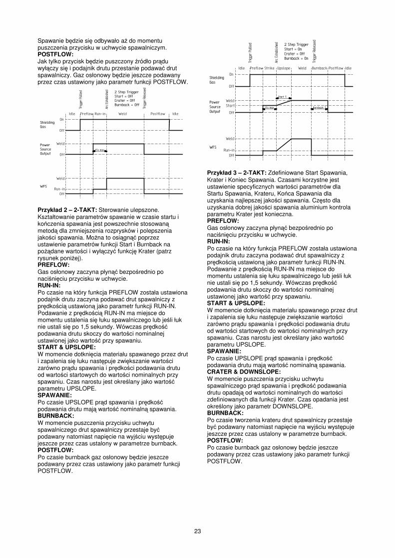
Example 2: 2 Step Trigger: Improved Arc Start and Arc End. Tailoring the arc start and arc end is a common method for reducing spatter and improving weld quality. This can be accomplished with the Start and Burnback functions set to a desired values and Crater set to OFF (See Figure Below). For this sequence: • PREFLOW: Shielding gas begins to flow
immediately when the gun trigger is pulled. • RUN-IN: After preflow time expires, the power
source regulates to the start output and wire is advanced towards the work piece at the Run-In WFS. If an arc is not established within 1.5 seconds, the power source output and wire feed speed skips to the weld settings.
• START & UPSLOPE: Once the wire touches the work and an arc is established, both the machine
12
output and the wire feed speed ramp to the weld settings throughout the start time. The time period of ramping from the start settings to the weld settings is called UPSLOPE.
• WELD: After upslope, the power source output and the wire feed speed continue at the weld settings.
• BURNBACK: As soon as the trigger is released, the wire feed speed is turned OFF and the machine output continues for the burnback time.
• POSTFLOW: Next, the machine output is turned OFF and shielding gas continues until the post flow timer expires.
��
���
���
���
����
����
����
�����������
�����������������
!�
���� ������ ������ ���� ������� ����
�������� �����
���������������
����������������
��������������������"����������"��##$���%����"���
�&����'
������� ������
�����$���%������
��������
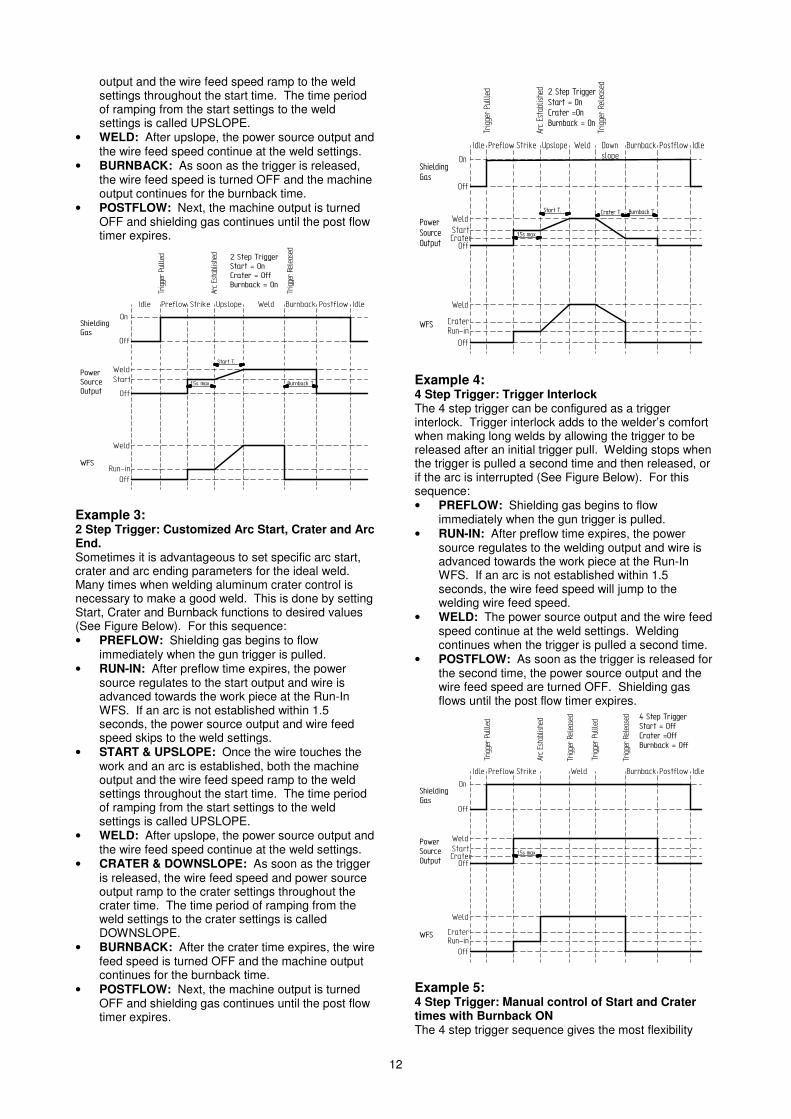
Example 3: 2 Step Trigger: Customized Arc Start, Crater and Arc End. Sometimes it is advantageous to set specific arc start, crater and arc ending parameters for the ideal weld. Many times when welding aluminum crater control is necessary to make a good weld. This is done by setting Start, Crater and Burnback functions to desired values (See Figure Below). For this sequence: • PREFLOW: Shielding gas begins to flow
immediately when the gun trigger is pulled. • RUN-IN: After preflow time expires, the power
source regulates to the start output and wire is advanced towards the work piece at the Run-In WFS. If an arc is not established within 1.5 seconds, the power source output and wire feed speed skips to the weld settings.
• START & UPSLOPE: Once the wire touches the work and an arc is established, both the machine output and the wire feed speed ramp to the weld settings throughout the start time. The time period of ramping from the start settings to the weld settings is called UPSLOPE.
• WELD: After upslope, the power source output and the wire feed speed continue at the weld settings.
• CRATER & DOWNSLOPE: As soon as the trigger is released, the wire feed speed and power source output ramp to the crater settings throughout the crater time. The time period of ramping from the weld settings to the crater settings is called DOWNSLOPE.
• BURNBACK: After the crater time expires, the wire feed speed is turned OFF and the machine output continues for the burnback time.
• POSTFLOW: Next, the machine output is turned OFF and shielding gas continues until the post flow timer expires.
��
���
���
���
����
����
����
�����������
�����������������
!�
���� ������ ������ ���� ������� ����
�������� �����
�������������
��
����������������
��������������������"����������"��$���%����"���
�&����'
������� ������
�����
$���%��������������
!��������
"�����
���������
"�����
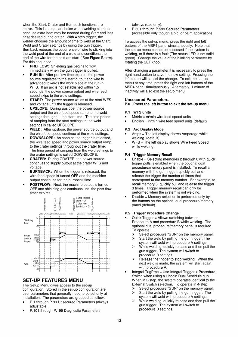
Example 4: 4 Step Trigger: Trigger Interlock The 4 step trigger can be configured as a trigger interlock. Trigger interlock adds to the welder’s comfort when making long welds by allowing the trigger to be released after an initial trigger pull. Welding stops when the trigger is pulled a second time and then released, or if the arc is interrupted (See Figure Below). For this sequence: • PREFLOW: Shielding gas begins to flow
immediately when the gun trigger is pulled. • RUN-IN: After preflow time expires, the power
source regulates to the welding output and wire is advanced towards the work piece at the Run-In WFS. If an arc is not established within 1.5 seconds, the wire feed speed will jump to the welding wire feed speed.
• WELD: The power source output and the wire feed speed continue at the weld settings. Welding continues when the trigger is pulled a second time.
• POSTFLOW: As soon as the trigger is released for the second time, the power source output and the wire feed speed are turned OFF. Shielding gas flows until the post flow timer expires.
��
���
���
���
����
����
����
�����������
�����������������
!�
���� ������ ������ ���� ������� ����
�������� �����
���������������
���������������� (�������������
������"��##�������"�##$���%����"��##
�&����'
������
�����"�����
"�����
�������� �����
����������������
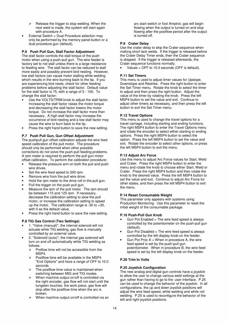
Example 5: 4 Step Trigger: Manual control of Start and Crater times with Burnback ON The 4 step trigger sequence gives the most flexibility
13
when the Start, Crater and Burnback functions are active. This is a popular choice when welding aluminum because extra heat may be needed during Start and less heat desired during crater. With 4 step trigger, the welder chooses the amount of time to weld at the Start, Weld and Crater settings by using the gun trigger. Burnback reduces the occurrence of wire to sticking into the weld pool at the end of a weld and conditions the end of the wire for the next arc start ( See Figure Below). For this sequence: • PREFLOW: Shielding gas begins to flow
immediately when the gun trigger is pulled. • RUN-IN: After preflow time expires, the power
source regulates to the start output and wire is advanced towards the work piece at the run-in WFS. If an arc is not established within 1.5 seconds, the power source output and wire feed speed skips to the weld settings.
• START: The power source welds at the start WFS and voltage until the trigger is released.
• UPSLOPE: During upslope, the power source output and the wire feed speed ramp to the weld settings throughout the start time. The time period of ramping from the start settings to the weld settings is called UPSLOPE.
• WELD: After upslope, the power source output and the wire feed speed continue at the weld settings.
• DOWNSLOPE: As soon as the trigger is released, the wire feed speed and power source output ramp to the crater settings throughout the crater time. The time period of ramping from the weld settings to the crater settings is called DOWNSLOPE.
• CRATER: During CRATER, the power source continues to supply output at the crater WFS and voltage.
• BURNBACK: When the trigger is released, the wire feed speed is turned OFF and the machine output continues for the burnback time.
• POSTFLOW: Next, the machine output is turned OFF and shielding gas continues until the post flow timer expires.
��
���
���
���
����
����
����
�����������
�����������������
!�
���� ������������ ���� ������� ����
�������� �����
���������������
���������������� (�������������
������"����������"��$���%����"���
�&����'
������
�����
$���%��������������
"�����
���������
"�����
�������� �����
����������������
����� ������� !�������� "�����
�����
SET-UP FEATURES MENU The Setup Menu gives access to the set-up configuration. Stored in the set-up configuration are user parameters that generally need to be set only at installation. The parameters are grouped as follows: • P.1 through P.99 Unsecured Parameters (always
adjustable). • P.101 through P.199 Diagnostic Parameters
(always read only). • P.501 through P.599 Secured Parameters
(accessible only though a p.c. or palm application). To access the set-up menu, press the right and left buttons of the MSP4 panel simultaneously. Note that the set-up menu cannot be accessed if the system is welding, or if there is a fault (The status LED is not solid green). Change the value of the blinking parameter by rotating the SET knob. After changing a parameter it is necessary to press the right hand button to save the new setting. Pressing the left button will cancel the change. To exit the set-up menu at any time, press the right and left buttons of the MSP4 panel simultaneously. Alternately, 1 minute of inactivity will also exit the setup menu. Unsecured Parameters. P.0 Press the left button to exit the set-up menu. P.1 WFS units • Metric = m/min wire feed speed units • English = in/min wire feed speed units (default) P.2 Arc Display Mode • Amps = The left display shows Amperage while
welding. (default) • WFS = The left display shows Wire Feed Speed
while welding. P.4 Trigger Memory Recall • Enable = Selecting memories 2 through 6 with quick
trigger pulls is enabled when the optional dual procedure/memory panel is installed. To recall a memory with the gun trigger, quickly pull and release the trigger the number of times that correspond to the memory number. For example, to recall memory 3, quickly pull and release the trigger 3 times. Trigger memory recall can only be performed when the system is not welding.
• Disable = Memory selection is performed only by the buttons on the optional dual procedure/memory panel (default).
P.5 Trigger Procedure Change • Quick Trigger = Allows switching between
Procedure A and procedure B while welding. The optional dual procedure/memory panel is required. To operate: � Select procedure “GUN” on the memory panel. � Start the weld by pulling the gun trigger. The
system will weld with procedure A settings. � While welding, quickly release and then pull the
gun trigger. The system will switch to procedure B settings.
� Release the trigger to stop welding. When the next weld is made, the system will start again with procedure A.
• Integral TrigProc = Use Integral Trigger + Procedure Switch when using a Lincoln Dual Schedule gun. When in 2-step, the system operates identical to the External Switch selection. To operate in 4-step: � Select procedure “GUN” on the memory panel. � Start the weld by pulling the gun trigger. The
system will weld with procedure A settings. � While welding, quickly release and then pull the
gun trigger. The system will switch to procedure B settings.
14
� Release the trigger to stop welding. When the next weld is made, the system will start again with procedure A.
• External Switch = Dual Procedure selection may only be performed by the memory panel button or a dual procedure gun (default).
P.6 Push Pull Gun, Stall Factor Adjustment The stall factor controls the stall torque of the push motor when using a push-pull gun. The wire feeder is factory set to not stall unless there is a large resistance to feeding wire. The stall factor can be reduced to stall more easily and possibly prevent bird nesting. However, low stall factors can cause motor stalling while welding which results in the wire burning back to the tip. If you are experiencing bird nests, check for other feeding problems before adjusting the stall factor. Default value for the stall factor is 75, with a range of 5 - 100. To change the stall factor: • Use the VOLTS/TRIM knob to adjust the stall factor.
Increasing the stall factor raises the motor torque and decreasing the stall factor lowers the motor torque. Do not increase the stall factor more than necessary. A high stall factor may increase the occurrence of bird nesting and a low stall factor may cause the wire to burn back to the tip.
• Press the right hand button to save the new setting. P.7 Push Pull Gun, Gun Offset Adjustment The pushpull gun offset calibration adjusts the wire feed speed calibration of the pull motor. The procedure should only be performed when other possible corrections do not solve the push-pull feeding problems. A rpm meter is required to perform the pull gun motor offset calibration. To perform the calibration procedure: • Release the pressure arm on both the pull and push
wire drives. • Set the wire feed speed to 200 rpm. • Remove wire from the pull wire drive. • Hold the rpm meter to the drive roll in the pull gun. • Pull the trigger on the push-pull gun. • Measure the rpm of the pull motor. The rpm should
be between 115 and 125 rpm. If necessary, decrease the calibration setting to slow the pull motor, or increase the calibration setting to speed up the motor. The calibration range is -30 to +30, with 0 as the default value.
• Press the right hand button to save the new setting. P.8 TIG Gas Control (Two Settings) • 1. "Valve (manual)", the internal solenoid will not
actuate while TIG welding, gas flow is manually controlled by an external valve.
• 2. "Solenoid (auto)", the internal gas solenoid will turn on and off automatically while TIG welding as follows: � Preflow time will not be accessible from the
MSP4. � Postflow time will be available in the MSP4
"End Options" and have a range of OFF to 10.0 seconds.
� The postflow time value is maintained when switching between MIG and TIG modes.
� When machine output on/off is controlled via the right encoder, gas flow will not start until the tungsten touches, the work piece, gas flow will stop after the postflow time when the arc is broken.
� When machine output on/off is controlled via an
arc start switch or foot Amptrol, gas will begin flowing when the output is turned on and stop flowing after the postflow period after the output is turned off.
P.9 Crater Delay Use the crater delay to skip the Crater sequence when making short tack welds. If the trigger is released before the Crater Delay Timer ends, then the Crater sequence is skipped. If the trigger is released afterwards, the Crater sequence functions normally. • Values = OFF to 10.0 seconds (OFF is default). P.11 Set Timers This menu is used to adjust timer values for Upslope, Downslope and Restrike. Press the right button to enter the Set Timer menu. Rotate the knob to select the timer to adjust and then press the right button. Adjust the value of the timer by rotating the knob. Press the left MSP4 button to set the value and exit. Continue to adjust other timers as necessary, and then press the left button to exit the Set Timer menu. P.12 Travel Options This menu is used to change the travel options for a travel carriage, including starting and ending functions. The right MSP4 button to enter the Travel Options menu and rotate the encoder to select either starting or ending options. Press the right MSP4 button to select the option. Press the left MSP4 button to set the value and exit. Rotate the encoder to select other options, or press the left MSP4 button to exit the menu. P.13 Adjust Arc Force Use this menu to adjust Arc Force values for Start, Weld and Crater. Press the right MSP4 button to enter the menu and rotate the knob to choose either Start, Weld or Crater. Press the right MSP4 button and then rotate the knob to the desired value. Press the left MSP4 button to set the value and exit. Continue to adjust Arc Force for other states, and then press the left MSP4 button to exit the menu. P.14 Reset Consumable Weight This parameter only appears with systems using Production Monitoring. Use this parameter to reset the initial weight of the consumable package. P.16 Push-Pull Gun Knob • Gun Pot Enabled = The wire feed speed is always
controlled by the potentiometer on the push-pull gun (default).
• Gun Pot Disabled = The wire feed speed is always controlled by the left display knob on the feeder.
• Gun Pot Proc A = When in procedure A, the wire feed speed is set by the push-pull gun potentiometer. When in procedure B, the wire feed speed is set by the left display knob on the feeder.
P.20 Trim In Volts P.25 Joystick Configuration The new analog and digital gun controls have a joystick to allow the user to change various weld settings at the gun rather than having to go to the user interface. P.25 can be used to change the behavior of the joystick. In all configurations, the up and down joystick positions will adjust the wire feed speed, while welding and while not welding. P.25 is used to reconfigure the behavior of the left and right joystick positions.

15
• When P.25 is set to “Trim/Volts/etc.”, the left and right joystick positions will adjust Arc Length Trim, Arc Voltage, Power or STT Background Current based on the selected weld mode. For example, when a non-synergic STT weld mode is selected, the left and right joystick positions will adjust Background Current. When a Power mode is selected, the left and right joystick positions will adjust the Power (kW).
• When P.25 is set to “Memory+Trim/etc.”, the left and right joystick positions will select a user memory while not welding and adjust Trim/Voltage/Power/STT Background Current while welding.
• When P.25 is set to “Procedure A/B”, the left and right joystick positions will be used to select procedure A and B, while welding and while not welding. The left joystick position selects procedure A, the right joystick position selects procedure B.
Diagnostic Parameters P.80 Sense from Studs Use this parameter for diagnostic purposes only. When power is cycled, P.80 is automatically reset to False. • False = Sensing for the electrode (67) and work (21)
is determined by the DIP switches of the system. • True = Sensing for the electrode (67) and work (21)
is measured at the studs of the power source and the DIP switch settings are overridden.
P.99 Show Test Modes Many weld tables include special modes for testing and servicing the welding system. Set this parameter to YES to show all test modes. When the power source is turned off, the Show Test Modes parameter automatically reverts back to "NO". P.100 View Diagnostics Diagnostics are only used for servicing the Power Wave system. • Yes = Shows P.101 through P.500 in the SETUP
menu. • No = Only P.0 through P.100 are shown in the
SETUP menu. P.101 Event Logs Press the right MSP4 button to view the Event Logs. Rotate the encoder to select the object to read and then press the right MSP4 button. Various software information will appear about key system events. Press the left MSP4 button to exit. P.102 Fatal Logs Press the right MSP4 button to view the Fatal Logs. Rotate the encoder to select the module to read and then press the right MSP4 button. Various software information will appear about critical module actions. Press the left MSP4 button to exit. P.103 Software Version Press the right MSP4 button to view the software loaded into each module (p.c. board). Rotate the encoder to select the module to read and then press the right MSP4 button. The panel will display the main software version loaded into the module. Press the left MSP4 button to exit.
P.104 Hardware Version Press the right MSP4 button to view the hardware version of each module (p.c. board). Rotate the encoder to select the module to read and then press the right MSP4 button. The panel will display the main hardware version loaded into the module. Press the left MSP4 button to exit. P.105 Welding Software Press the right MSP4 button to view the welding software version inside the power source. Press the left MSP4 button to exit. P.106 Ethernet IP Address Press the right MSP4 button to view the IP address of the Ethernet board. If no Ethernet Board is installed, the display shows "No Enet Found". Press the left MSP4 button to exit. P.107 Power Source Press the right MSP4 button to view the type of power source connected to the control box. Press the left MSP4 button to exit. Maintenance
WARNING For any maintenance or repair operations it is recommended to contact the nearest technical service center or Lincoln Electric. Maintenance or repairs performed by unauthorized service centers or personnel will null and void the manufacturers warranty. The frequency of the maintenance operations may vary in accordance with the working environment where the machine is placed. Any noticeable damage should be reported immediately. Routine maintenance • Check condition of insulation and connections of the
work cables and input power supply cable. • Remove the spatters from the welding gun nozzle.
Spatters could interfere with the shielding gas flow to the arc.
• Check the welding gun condition: replace it, if necessary.
• Check condition and operation of the cooling fan. Keep clean its airflow slots.
Periodic maintenance Perform the routine maintenance and, in addition: • Keep clean the machine. Using a dry ( and low
pressure) airflow, remove the dust from the external case and from inside of the cabinet.
• Check condition of all connections and change if necessary.
• Check and tighten all screws.
WARNING Mains supply network must be disconnected from the machine before each maintenance and service. After each repair, perform proper tests to ensure safety.

16
Electromagnetic Compatibility (EMC) 11/04
This machine has been designed in accordance with all relevant directives and standards. However, it may still generate electromagnetic disturbances that can affect other systems like telecommunications (telephone, radio, and television) or other safety systems. These disturbances can cause safety problems in the affected systems. Read and understand this section to eliminate or reduce the amount of electromagnetic disturbance generated by this machine.
This machine has been designed to operate in an industrial area. To operate in a domestic area it is necessary to observe particular precautions to eliminate possible electromagnetic disturbances. The operator must install and operate this equipment as described in this manual. If any electromagnetic disturbances are detected the operator must put in place corrective actions to eliminate these disturbances
with, if necessary, assistance from Lincoln Electric. Before installing the machine, the operator must check the work area for any devices that may malfunction because of electromagnetic disturbances. Consider the following. • Input and output cables, control cables, and telephone cables that are in or adjacent to the work area and the
machine. • Radio and/or television transmitters and receivers. Computers or computer controlled equipment. • Safety and control equipment for industrial processes. Equipment for calibration and measurement. • Personal medical devices like pacemakers and hearing aids. • Check the electromagnetic immunity for equipment operating in or near the work area. The operator must be sure
that all equipment in the area is compatible. This may require additional protection measures. • The dimensions of the work area to consider will depend on the construction of the area and other activities that are
taking place. Consider the following guidelines to reduce electromagnetic emissions from the machine. • Connect the machine to the input supply according to this manual. If disturbances occur if may be necessary to take
additional precautions such as filtering the input supply. • The output cables should be kept as short as possible and should be positioned together. If possible connect the
work piece to ground in order to reduce the electromagnetic emissions. The operator must check that connecting the work piece to ground does not cause problems or unsafe operating conditions for personnel and equipment.
• Shielding of cables in the work area can reduce electromagnetic emissions. This may be necessary for special applications.
Technical Specifications
INPUT VOLTAGE WIRE FEED SPEED 34-44 Vdc 1.0-20 m/min
RATED OUTPUT AT 40°C Duty Cycle
(based on a 10 min. period)
100% 60%
Output Current
385 A 500 A
OUTPUT RANGE Welding Current Range
5-500 A Maximum Open Circuit Voltage
113 Vdc or Vac peak WIRE SIZES (mm)
Solid wires 0.6 to 1.6
Cored wires 1.0 to 2.0
Aluminium wires 1.0 to 1.6
PHYSICAL DIMENSIONS Height
440 mm Width
270 mm Length
636 mm Weight 12,3 Kg
Operating Temperature –10°C to +40°C
Storage Temperature -25°C to +55°C
17
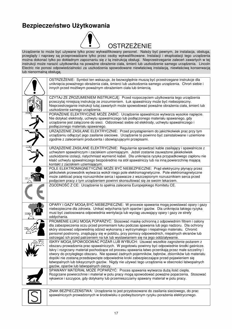
Bezpiecze�stwo U�ytkowania
OSTRZEENIE Urz�dzenie to mo�e by� u�ywane tylko przez wykwalifikowany personel. Nale�y by� pewnym, �e instalacja, obsługa, przegl�dy i naprawy s� przeprowadzane tylko przez osoby wykwalifikowane. Instalacji i eksploatacji tego urz�dzenia mo�na dokona� tylko po dokładnym zapoznaniu si� z t� instrukcj� obsługi. Nieprzestrzeganie zalece� zawartych w tej instrukcji mo�e narazi� u�ytkownika na powa�ne obra�enie ciała, �mier� lub uszkodzenie samego urz�dzenia. Lincoln Electric nie ponosi odpowiedzialno�ci za uszkodzenia spowodowane niewła�ciw� instalacj�, niewła�ciw� konserwacj� lub nienormaln� obsług�.
OSTRZEENIE: Symbol ten wskazuje, �e bezwzgl�dnie musz� by� przestrzegane instrukcje dla unikni�cia powa�nego obra�enia ciała, �mierci lub uszkodzenia samego urz�dzenia. Chro� siebie i innych przed mo�liwym powa�nym obra�eniem ciała lub �mierci�.
CZYTAJ ZE ZROZUMIENIEM INSTRUKCJ: Przed rozpocz�ciem u�ytkowania tego urz�dzenia przeczytaj niniejsz� instrukcj� ze zrozumieniem. Łuk spawalniczy mo�e by� niebezpieczny. Nieprzestrzeganie instrukcji tutaj zawartych mo�e spowodowa� powa�ne obra�enia ciała, �mier� lub uszkodzenie samego urz�dzenia.
PORAENIE ELEKTRYCZNE MOE ZABI�: Urz�dzenie spawalnicze wytwarza wysokie napi�cie. Nie dotyka� elektrody, uchwytu spawalniczego lub podł�czonego materiału spawanego, gdy urz�dzenie jest zał�czone do sieci. Odizolowa� siebie od elektrody, uchwytu spawalniczego i podł�czonego materiału spawanego.
URZ�DZENIE ZASILANE ELEKTRYCZNIE: Przed przyst�pieniem do jakichkolwiek prac przy tym urz�dzeniu odł�czy� jego zasilanie sieciowe. Urz�dzenie to powinno by� zainstalowane i uziemione zgodnie z zaleceniami producenta i obowi�zuj�cymi przepisami.
URZ�DZENIE ZASILANE ELEKTRYCZNIE: Regularnie sprawdza� kable zasilaj�cy i spawalnicze z uchwytem spawalniczym i zaciskiem uziemiaj�cym. Je�eli zostanie zauwa�one jakiekolwiek uszkodzenie izolacji, natychmiast wymieni� kabel. Dla unikni�cia ryzyka przypadkowego zapłonu nie kła�� uchwytu spawalniczego bezpo�rednio na stół spawalniczy lub na inn� powierzchni� maj�c� kontakt z zaciskiem uziemiaj�cym.
POLE ELEKTROMAGNETYCZNE MOE BY� NIEBEZPIECZNE: Pr�d elektryczny płyn�cy przez jakikolwiek przewodnik wytwarza wokół niego pole elektromagnetyczne. Pole elektromagnetyczne mo�e zakłóca� prac� rozruszników serca i spawacze z wszczepionym rozrusznikiem serca przed podj�ciem pracy z tym urz�dzeniem powinni skonsultowa� si� ze swoim lekarzem.
ZGODNO�� Z CE: Urz�dzenie to spełnia zalecenia Europejskiego Komitetu CE.
OPARY I GAZY MOG� BY� NIEBEZPIECZNE: W procesie spawania mog� powstawa� opary i gazy niebezpieczne dla zdrowia. Unika� wdychania tych oparów i gazów. Dla unikni�cia takiego ryzyka musi by� zastosowana odpowiednia wentylacja lub wyci�g usuwaj�cy opary i gazy ze strefy oddychania.
PROMIENIE ŁUKU MOG� POPARZY�: Stosowa� mask� ochronn� z odpowiednim filtrem i osłony dla zabezpieczenia oczu przed promieniami łuku podczas spawania lub jego nadzoru. Dla ochrony skóry stosowa� odpowiedni� odzie� wykonan� z wytrzymałego i niepalnego materiału. Chroni� personel postronny, znajduj�cy si� w pobli�u, przy pomocy odpowiednich, niepalnych ekranów lub ostrzega� ich przed patrzeniem na łuk lub wystawianiem si� na jego oddziaływanie.
ISKRY MOG� SPOWODOWA� POAR LUB WYBUCH: Usuwa� wszelkie zagro�enie po�arem z obszaru prowadzenia prac spawalniczych. W pogotowiu powinny by� odpowiednie �rodki ga�nicze. Iskry i rozgrzany materiał pochodz�ce od procesu spawania łatwo przenikaj� przez małe szczeliny i otwory do przyległego obszaru. Nie spawa� �adnych pojemników, b�bnów, zbiorników lub materiału dopóki nie zostan� przedsi�wzi�te odpowiednie kroki zabezpieczaj�ce przed pojawieniem si� łatwopalnych lub toksycznych gazów. Nigdy nie u�ywa� tego urz�dzenia w obecno�ci łatwopalnych gazów, oparów lub łatwopalnych cieczy.
SPAWANY MATERIAŁ MOE POPARZY�: Proces spawania wytwarza du�� ilo�� ciepła. Rozgrzane powierzchnie i materiał w polu pracy mog� spowodowa� powa�ne poparzenia. Stosowa� r�kawice i szczypce, gdy dotykamy lub przemieszczamy spawany materiał w polu pracy.
ZNAK BEZPIECZE STWA: Urz�dzenie to jest przystosowane do zasilania sieciowego, do prac spawalniczych prowadzonych w �rodowisku o podwy�szonym ryzyku pora�enia elektrycznego.
18
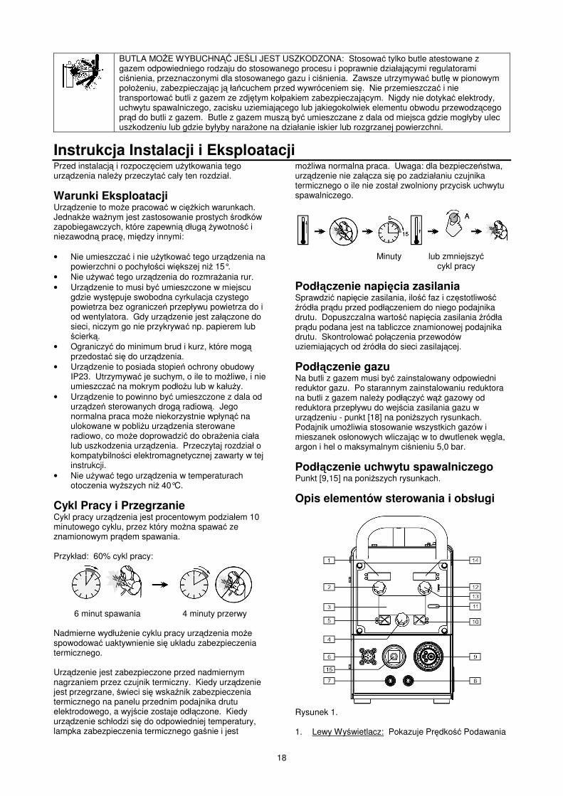
BUTLA MOE WYBUCHN�� JE�LI JEST USZKODZONA: Stosowa� tylko butle atestowane z gazem odpowiedniego rodzaju do stosowanego procesu i poprawnie działaj�cymi regulatorami ci�nienia, przeznaczonymi dla stosowanego gazu i ci�nienia. Zawsze utrzymywa� butl� w pionowym poło�eniu, zabezpieczaj�c j� ła�cuchem przed wywróceniem si�. Nie przemieszcza� i nie transportowa� butli z gazem ze zdj�tym kołpakiem zabezpieczaj�cym. Nigdy nie dotyka� elektrody, uchwytu spawalniczego, zacisku uziemiaj�cego lub jakiegokolwiek elementu obwodu przewodz�cego pr�d do butli z gazem. Butle z gazem musz� by� umieszczane z dala od miejsca gdzie mogłyby ulec uszkodzeniu lub gdzie byłyby nara�one na działanie iskier lub rozgrzanej powierzchni.
Instrukcja Instalacji i Eksploatacji Przed instalacj� i rozpocz�ciem u�ytkowania tego urz�dzenia nale�y przeczyta� cały ten rozdział.
Warunki Eksploatacji Urz�dzenie to mo�e pracowa� w ci��kich warunkach. Jednak�e wa�nym jest zastosowanie prostych �rodków zapobiegawczych, które zapewni� dług� �ywotno�� i niezawodn� prac�, mi�dzy innymi: • Nie umieszcza� i nie u�ytkowa� tego urz�dzenia na
powierzchni o pochyło�ci wi�kszej ni� 15°. • Nie u�ywa� tego urz�dzenia do rozmra�ania rur. • Urz�dzenie to musi by� umieszczone w miejscu
gdzie wyst�puje swobodna cyrkulacja czystego powietrza bez ogranicze� przepływu powietrza do i od wentylatora. Gdy urz�dzenie jest zał�czone do sieci, niczym go nie przykrywa� np. papierem lub �cierk�.
• Ograniczy� do minimum brud i kurz, które mog� przedosta� si� do urz�dzenia.
• Urz�dzenie to posiada stopie� ochrony obudowy IP23. Utrzymywa� je suchym, o ile to mo�liwe, i nie umieszcza� na mokrym podło�u lub w kału�y.
• Urz�dzenie to powinno by� umieszczone z dala od urz�dze� sterowanych drog� radiow�. Jego normalna praca mo�e niekorzystnie wpłyn�� na ulokowane w pobli�u urz�dzenia sterowane radiowo, co mo�e doprowadzi� do obra�enia ciała lub uszkodzenia urz�dzenia. Przeczytaj rozdział o kompatybilno�ci elektromagnetycznej zawarty w tej instrukcji.
• Nie u�ywa� tego urz�dzenia w temperaturach otoczenia wy�szych ni� 40°C.
Cykl Pracy i Przegrzanie Cykl pracy urz�dzenia jest procentowym podziałem 10 minutowego cyklu, przez który mo�na spawa� ze znamionowym pr�dem spawania. Przykład: 60% cykl pracy:
6 minut spawania 4 minuty przerwy
Nadmierne wydłu�enie cyklu pracy urz�dzenia mo�e spowodowa� uaktywnienie si� układu zabezpieczenia termicznego. Urz�dzenie jest zabezpieczone przed nadmiernym nagrzaniem przez czujnik termiczny. Kiedy urz�dzenie jest przegrzane, �wieci si� wska�nik zabezpieczenia termicznego na panelu przednim podajnika drutu elektrodowego, a wyj�cie zostaje odł�czone. Kiedy urz�dzenie schłodzi si� do odpowiedniej temperatury, lampka zabezpieczenia termicznego ga�nie i jest
mo�liwa normalna praca. Uwaga: dla bezpiecze�stwa, urz�dzenie nie zał�cza si� po zadziałaniu czujnika termicznego o ile nie został zwolniony przycisk uchwytu spawalniczego.
Minuty lub zmniejszy�
cykl pracy
Podł�czenie napi�cia zasilania Sprawdzi� napi�cie zasilania, ilo�� faz i cz�stotliwo�� �ródła pr�du przed podł�czeniem do niego podajnika drutu. Dopuszczalna warto�� napi�cia zasilania �ródła pr�du podana jest na tabliczce znamionowej podajnika drutu. Skontrolowa� poł�czenia przewodów uziemiaj�cych od �ródła do sieci zasilaj�cej.
Podł�czenie gazu Na butli z gazem musi by� zainstalowany odpowiedni reduktor gazu. Po starannym zainstalowaniu reduktora na butli z gazem nale�y podł�czy� w�� gazowy od reduktora przepływu do wej�cia zasilania gazu w urz�dzeniu - punkt [18] na poni�szych rysunkach. Podajnik umo�liwia stosowanie wszystkich gazów i mieszanek osłonowych wliczaj�c w to dwutlenek w�gla, argon i hel o maksymalnym ci�nieniu 5,0 bar.
Podł�czenie uchwytu spawalniczego Punkt [9,15] na poni�szych rysunkach.
Opis elementów sterowania i obsługi
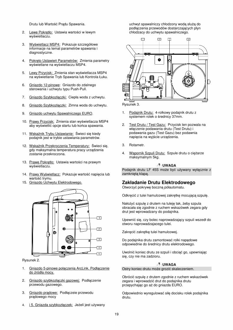
Rysunek 1. 1. Lewy Wy�wietlacz: Pokazuje Pr�dko�� Podawania
19
Drutu lub Warto�� Pr�du Spawania. 2. Lewe Pokr�tło: Ustawia warto�ci w lewym
wy�wietlaczu. 3. Wy�wietlacz MSP4: Pokazuje szczegółowe
informacje na temat parametrów spawania i diagnostyczne.
4. Pokr�to Ustawie� Parametrów: Zmienia parametry
wy�wietlane na wy�wietlaczu MSP4. 5. Lewy Przycisk: Zmienia stan wy�wietlacza MSP4
na wy�wietlanie Tryb Spawania lub Kontrola Łuku. 6. Gniazdo 12-pinowe: Gniazdo do zdalnego
sterowania i uchwytu typu Push-Pull. 7. Gniazdo Szybkozł�czki: Ciepła woda z uchwytu. 8. Gniazdo Szybkozł�czki: Zimna woda do uchwytu. 9. Gniazdo uchwytu Spawalniczego EURO. 10. Prawy Przycisk: Zmienia stan wy�wietlacza MSP4
aby wy�wietli� opcje startu lub ko�ca spawania. 11. Wska�nik Trybu Ustawianie: �wieci si� kiedy
podajnik jest w trybie ustawiania parametrów. 12. Wska�nik Przekroczenia Temperatury: �wieci si�,
gdy maksymalna temperatura pracy urz�dzenia zostanie przekroczona.
13. Prawe Pokr�tło: Ustawia warto�ci na prawym
wy�wietlaczu. 14. Prawy Wy�wietlacz: Pokazuje warto�� napi�cia lub
warto�� trymu. 15. Gniazdo Uchwytu Elektrodowego.
Rysunek 2. 1. Gniazdo 5-pinowe poł�czenia ArcLink. Podł�czenie
do �ródła mocy. 2. Gniazdo szybkozł�czki gazowej: Podł�czenie
przewodu gazowego. 3. Gniazdo pr�dowe: Podł�czeie przewodu
pr�dowego mocy 4. i 5. Gniazda szybkozł�czek: Je�eli jest u�ywany
uchwyt spawalniczy chłodzony wod� słu�� do podł�czenia przewodów dostarczaj�cych płyn chłodzacy do uchwytu spawalniczego.
Rysunek 3. 1. Podajnik Drutu: 4-rolkowy podajnik drutu z
systemem rolek o �rednicy 37mm. 2. Test Drutu / Test Gazu: Przycisk ten pozwala na
wł�czenie podawania drutu (Test Drutu) i podawania gazu (Test Gazu) bez podawnia napi�cia na wyj�cie urz�dzenia.
3. Rotametr. 4. Wspornik Szpuli Drutu: Szpule drutu o ci��arze
maksymalnym 5kg.
UWAGA Podajnik drutu LF 45S mo�e by� u�ywany wył�cznie z zamkni�t� klap�.
Zakładanie Drutu Elektrodowego Otworzy� pokryw� boczn� półautomatu. Odkr�ci� z tulei hamulcowej zakr�tk� mocuj�c� szpul�. Nało�y� szpul� z drutem na tulej� tak, �eby szpula obracała si� zgodnie z ruchem wskazówek zegara gdy drut jest wprowadzany do podajnika. Upewni� si�, czy bolec naprowadzaj�cy szpuli wszedł do otworu naprowadzajacego tulei. Zakr�ci� zakr�tk� tulei hamulcowej. Do podajnika drutu zamontowa� rolki nap�dowe odpowiednie do �rednicy drutu elektrodowego. Uwolni� koniec drutu ze szpuli i obci�� go, upewniaj�c si�, czy nie ma zadzioru.
UWAGA Ostry koniec drutu mo�e grozi� skaleczeniem. Obróci� szpul� z drutem zgodnie z ruchem wskazówek zegara i wprowadzi� drut do podajnika drutu przepychaj�c go a� do gniazda EURO. Odpowiednio wyregulowa� sił� docisku rolek podajnika drutu.
20
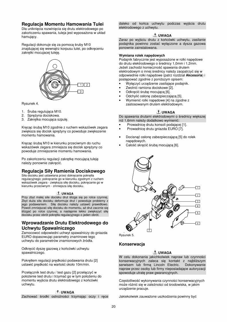
Regulacja Momentu Hamowania Tulei Dla unikni�cia rozwini�cia si� drutu elektrodowego po zako�czeniu spawania, tuleja jest wyposa�ona w układ hamuj�cy. Regulacji dokonuje si� za pomoc� �ruby M10 znajduj�cej si� wewn�trz korpusu tulei, po odkr�ceniu zakr�tki mocujacej tulej�.
Rysunek 4. 1. �ruba reguluj�ca M10. 2. Spr��yna dociskowa. 3. Zakr�tka mocuj�ca szpul�. Kr�c�c �rub� M10 zgodnie z ruchem wskazówek zegara zwi�ksza si� docisk spr��yny co powoduje zwi�kszenie momentu hamowania. Kr�c�c �rub� M10 w kierunku przeciwnym do ruchu wskazówek zegara zmniejsza si� docisk spr��yny co powoduje zmniejszenie momentu hamowania. Po zako�czeniu regulacji zakr�tk� mocuj�c� tulej� nale�y ponownie zakr�ci�.
Regulacja Siły Ramienia Dociskowego Siła docisku jest ustawiana przez dokr�canie pokr�tła regulacyjnego; pokr�canie go w kierunku zgodnym z ruchem wskazówek zegara - zwi�ksza sił� docisku, pokr�canie go w kierunku przeciwnym - zmniejsza sił� docisku.
UWAGA Przy zbyt małej sile docisku drut �lizga si� po rolce czynnej. Zbyt du�a siła docisku deformuje drut i powoduje problemy z jego podawaniem. Sił� docisku nale�y ustawi� prawidłowo. Powoli zmniejsza� sił� docisku do momentu, a� drut zacznie si� �lizga� po rolce czynnej, a nast�pnie lekko zwi�kszy� sił� docisku przez obrót pokr�tła regulacyjnego o jeden obrót.
Wprowadzanie Drutu Elektrodowego do Uchwytu Spawalniczego Zamocowo� odpowiedni uchwyt spawalniczy do gniazda EURO dopasowuj�c parametry znaminowe tego uchwytu do parametrów znamionowych �ródła. Odkr�ci� dysz� gazow� z ko�cówki uchwytu spawalniczego. Pokr�tłem regulacji pr�dko�ci podawania drutu [2] ustawi� pr�dko�� na warto�� około 10m/min. Przeł�cznik test drutu / test gazu [2] przeł�czy� w poło�enie test drutu i trzyma� go w tym poło�eniu do momentu wyj�cia drutu elektrodowego z ko�cówki uchwytu.
UWAGA Zachowa� �rodki ostro�no�ci trzymaj�c oczy i r�ce
daleko od ko�ca uchwytu podczas wyj�cia drutu elektrodowego z uchwytu.
UWAGA Zaraz po wyj�ciu drutu z ko�cówki uchwytu, zasilanie podajnika powinno zosta� wył�czone a dysza gazowa ponownie zainstalowana. Wymiana rolek nap�dowych Podajnik fabrycznie jest wyposa�one w rolki nap�dowe do drutu elektrodowego o �rednicy 1,0mm i 1,2mm. Je�eli zachodzi konieczno�� spawania drutem elektrodowym o innej �rednicy nale�y zaopatrzy� si� w odpowiednie rolki nap�dowe (patrz rozdział Akcesoria) i post�powa� zgodnie z poni�szym opisem: • Wył�czy� urz�dzenie zasilaj�ce podajnik. • Zwolni� ramiona dociskowe [2]. • Odkr�ci� �rub� mocuj�c� [6]. • Odchyli� osłon� zabezpieczaj�c� [5]. • Wymieni� rolki nap�dowe [4] na zgodne z
zastosowanym drutem elektrodowym.
UWAGA Do spawania drutami elektrodowymi o �rednicy wi�kszej ni� 1,6mm nale�y dodatkowo wymieni�: • Prowadnic� drutu konsoli podaj�cej [1]. • Prowadnic� drutu gniazda EURO [7]. • Docisn�� osłon� zabezpieczaj�c� [5] do rolek
nap�dowych. • Cało�� skr�ci� �rub� mocuj�c� [6].
, Rysunek 5. Konserwacja
UWAGA W celu dokonania jakichkolwiek napraw lub czynno�ci konserwacyjnych zaleca si� kontakt z najbli�szym serwisem lub firm� Lincoln Electric. Dokonywanie napraw przez osoby lub firmy nieposiadaj�ce autoryzacji spowoduje utrat� praw gwarancyjnych. Cz�stotliwo�� wykonywania czynno�ci konserwacyjnych mo�e ró�ni� si� w zale�no�ci od �rodowiska, w jakim urz�dzenie pracuje. Jakiekolwiek zauwa�one uszkodzenia powinny by�
21
natychmiastowo zgłaszane.
Konserwacja podstawowa • Sprawdza� stan izolacji i poł�cze� kabli
spawalniczych i przewodu zasilaj�cego. • Usuwa� odpryski z dyszy gazowej uchwytu
spawalniczego. Rozpryski mog� przenosi� si� z gazem osłonowym do łuku.
• Sprawdza� stan uchwytu spawalniczego. Wymienia� go, je�li to konieczne.
• Sprawdza� stan i działanie wentylatora chłodz�cego. Utrzymywa� czyste otwory wlotu i wylotu powietrza chłodz�cego.
Konserwacja okresowa Wykonywa� konserwacj� podstawow� oraz, dodatkowo: • Utrzymywa� urz�dzenie w czysto�ci. Wykorzystuj�c
strumie� suchego powietrza (pod niskim ci�nieniem) usun�� kurz z cz��ci zewn�trznych obudowy i z wn�trza spawarki.
• Sprawdzi� stan wszystkich styków elektrycznych i poprawi�, je�li jest taka konieczno��.
• Sprawdza� i dokr�ca� wszystkie �ruby.
UWAGA Sie� zasilaj�ca musi by� odł�czona od urz�dzenia przed ka�d� czynno�ci� konserwacyjn� i serwisow�. Po ka�dej naprawie wykona� odpowiednie sprawdzenie w celu zapewnienia bezpiecze�stwa u�ytkowania. Spawanie Technologi� Kształtowania Przebiegu �ródła Pr�du
Uwaga W procesie spawania wiele zmiennych ma wpływ na proces spawania i na ostateczny efekt, które s� poza kontrol� parametrów wprowadzonych do programu przez Lincoln Electric. W�ród tych zmiennych s�: skład chemiczny materiału, temperatura, kształt . metoda produkcji, wymagania serwisowe. Dost�pny zakres programów spawania mo�e nie by� odpowiedni do wszystkich zastosowa�. Jest wyłaczn� odpowiedzialno�ci� u�ytkownika dobór programu spawania. Kroki jaki musi podj�� spawacz przy przygotowaniu urz�dzenia do spawania zmieniaj� si� zale�nie od metody spawania. Elestyczno�� interfejsu u�ytkownika pozwala na szybki dobór optymalnych parametrów spawania. Po pierwsze nale�y rozwa�y� proces spawania i rodzaj materiałów spawanych. Wybra� materiał elektrody, �rednic�, gaz osłonowy i proces (GMAW, SMAW, etc.). Po drugie znale�� w oprogramowaniu numer programu najlepiej dopasowuje si� do po��danego procesu spawania. Standardowy zakres programów dostarczany z urz�dzeniem obejmuje szeroki zakres ogólnych procesów spawania i spełnia wi�kszo� wymaga� u�ytkowników. Wszystkie ustawienia mo�na wprowadzi� z poziomu interfejsu u�ytkownika.
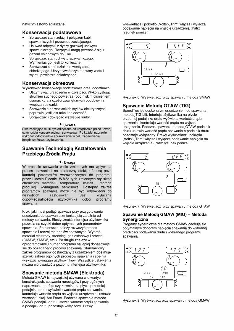
Spawanie metod� SMAW (Elektroda) Metoda SMAW is najcz��ciej u�ywana w otwartych konstrukcjach, spawaniu ruroci�gów i przy ogólnych naprawach. Interfejs u�ytkownika na płycie przedniej podajnika drutu wy�wietla warto�� pr�du spawania, kontroluje warto�� pr�du na wyj�ciu urz�dzenia i ustawia warto�� funkcji Arc Force. Podczas spawania metod� SMAW podajnik drutu ustawia warto�� pr�du spawania a podajnik drutu pozostaje wył�czony. Prawy
wy�wietlacz i pokr�tło „Volts”-„Trim” wł�cza i wył�cza podawanie napi�cia na wyj�cie urz�dzenia (Patrz rysunek poni�ej).
������
���������
��������������
Rysunek 6. Wy�wietlacz przy spawaniu metod� SMAW
Spawanie Metod� GTAW (TIG) SpeedTec jes doskonałym urz�dzeniem do spawania metod� TIG Lift. Interfejs u�ytkownika na płycie przedniej podajnika drutu wy�wietla warto�� pr�du spawania i kontroluje warto�� pr�du na wyj�ciu urz�dzenia. Podczas spawania metod� GTAW podajnik drutu ustawia warto�� pr�du spawania a podajnik drutu pozostaje wył�czony. Prawy wy�wietlacz i pokr�tło „Volts”-„Trim” wł�cza i wył�cza podawanie napi�cia na wyj�cie urz�dzenia (Patrz rysunek poni�ej).
������
�
�
Rysunek 7. Wy�wietlacz przy spawaniu metod� GTAW Spawanie Metod� GMAW (MIG) – Metoda Synergiczna Progamy synergiczne dla metody GMAW cechuj� si� optymalnym doborem napi�cia spawania do wybranej pr�dko�ci podawania drutu i wybranego programu spawania.
�����������
���������������������� ������
�����������������
��
Rysunek 8. Wy�wietlacz przy spawaniu metod� GMAW
22
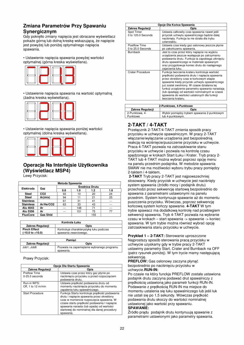
Zmiana Parametrów Przy Spawaniu Synergicznym Gdy pokr�tło zmiany napi�cia jest obracane wy�wietlacz poka�e górn� lub doln� kresk� wskazuj�c�, �e napi�cie jest powy�ej lub poni�ej optymalnego napi�cia spawania. • Ustawienie napi�cia spawania powy�ej warto�ci optymalnej (górna kreska wy�wietlana).
• Ustawienie napi�cia spawania na warto�� optymaln� (�adna kreska wy�wietlana).
• Ustawienie napi�cia spawania poni�ej warto�ci optymalnej (dolna kreska wy�wietlana).
Operacje Na Interfejsie U�ytkownika (Wy�wietlacz MSP4) Lewy Przycisk:
Metoda Spawania
Elektroda Gaz �rednica Drutu 0.8 1.0 1.2 1.6
Steel CO2 93 10 20 24 Steel Ar(mix) 94 11 21 25
Stainless 61 31 41 --- Stainless Ar/He/CO2 63 33 43 --- Alu 4043 Ar --- 148 71 --- Alu 5356 Ar --- 151 75 77 FluxCore Gas Shld 155
Kontrola Łuku Zakres Regulacji Opis
Pinch Effect (-10.0 to +10.0)
Kontroluje charakterystyk� łuku podczas spawania zwarciowego.
Pami�
Zakres Regulacji Opis Job1..Job8 Pozwala na zapami�tanie wybranego programu
spawania. Prawy Przycisk:
Opcje Dla Startu Spawania Zakres Regulacji Opis
Preflow Time 0-25.0 seconds
Ustawia czas przez który gaz płynie po naci�ni�ciu przycisku a przed rozpocz�ciem podawania drutu.
Run-in WFS: Off, 1 to 12 m/min
Ustawia pr�dko�� podawania drutu od momentu naci�ni�cia przycisku do momentu zapalenia łuku spawalniczego.
Start Procedure Funkcja Startu kontroluje pr�dko�� podawania drutu i napi�cie spawania przez okre�lony czas w momencie rozpocz�cia spawania. W czasie startu pr�dko�� podawania I napi�cie spawania narasta (lub opada) od warto�ci startowej do nominalnej dla danej procedury spawania.
Opcje Dla Ko�ca Spawania Zakres Regulacji Opis Spot Timer 0 to 120.0 Seconds
Ustawia całkowity czas spawania nawet je�li przycisk uchwytu spawalniczego b�dzie dalej naci�ni�ty. Funkcja ta nie działa dla trybu czterotaktu.
Postflow Time 0 to 25.0 Seconds
Ustawia czas kiedy gaz osłonowy jeszcze płynie po zako�czeniu spawania.
Burnback Jest to czas przez który napi�cie na wyj�ciu urz�dzenia jeszcze wyst�puje po zatrzymaniu podawania drutu. Funkcja ta zapobiega utkni�ciu drutu spawalniczego w materiale spawanym oraz przygotowuje koniec drutu do nast�pnego zajarzenia łuku.
Crater Procedure Funkcja tworzenia krateru kontroluje warto�� pr�dko�ci podawania drutu i napi�cia spawania przez okre�lony czas w ko�cowym etapie spawanie kiedy przycisk uchwytu spawalniczego ju� został zwolniony. W czasie działania tej funkcji urz�dzenie parametry spawania narastaj� (lub opadaj�) od warto��i nominalnych w czasie spawania do warto�ci ustalonych dla funkcji tworzenia krateru.
2-Punktowe, 4-Punktowe
Zakres Regulacji Opis 2-Punktowe, 4-Punktowe
Wybór pomi�dzy trybem spawania 2-punktowym lub 4-punktowym.
2-TAKT / 4-TAKT Przeł�cznik 2-TAKT/4-TAKT zmienia sposób pracy przycisku w uchwycie spawalniczym. W pracy 2-TAKT wł�czanie/wył�czanie urz�dzenia jest bezpo�redni� reakcj� na wci�ni�cie/puszczenie przycisku w uchwycie. Praca 4-TAKT pozwala na zatrzaskiwanie stanu przycisku w uchwycie i pozwala na kontrol� czasu sp�dzonego w krokach Start Łuku i Krater. Tryb pracy 2-TAKT lub 4-TAKT mo�na wybra� poprzez opcj� menu na panelu przednim podajnika. W metodzie spawania SMAW nie ma mo�liwo�ci wyboru trybu pracy pomi�dzy 2-taktem i 4-taktem, 2-TAKT Tryb pracy 2-TAKT jest najpowszechniej stosowany. Kiedy przycisk w uchwycie jest naci�ni�ty system spawania (�ródło mocy i podajnik drutu) przechodzi przez sekwencj� startow� bezpo�rednio do spawania z parametrami ustawionymi na panelu przednim. System kontynuuje spawanie a� do momentu puszczenia przycisku. Wówczas, poprzez sekwencj� ko�cow� system ko�czy spawanie. 4-TAKT W tym trybie spawacz ma dodatkow� kontrol� nad przebiegiem sekwencji spawania. Tryb 4-TAKT pozwala na wybranie czasu w krokach – start spawania -> spawanie -> koniec spawania. W tym trybie mo�na równie� wybra� opcj� zatrzaskiwania stanu przycisku w uchwycie. Przykład 1 – 2-TAKT: Sterowanie uproszczone Najprostszy sposób sterowania prac� przycisku w uchwycie uzyskamy gdy w trybie pracy 2-TAKT ustawimy parametry Start, Crater and Burnback na OFF (patrz rysunek poni�ej). W tym trycie mamy nast�puj�c� sekwencj�. PREFLOW: Gas osłonowy zaczyna płyn�� bezpo�rednio po naci�ni�ciu przycisku w uchwycie.RUN-IN: Po czasie na który funckja PREFLOW została ustawiona podajnik drutu zaczyna podawa� drut spawalniczy z pr�dko�ci� ustawion� jako parametr funkcji RUN-IN. Podawanie z pr�dko�ci� RUN-IN ma miejsce do momentu ustalenia si� łuku spawalniczego lub je�li łuk nie ustali si� po 1,5 sekundy. Wówczas pr�dko�� podawania drutu skoczy do warto�ci nominalnej ustawionej jako warto�� przy spawaniu. SPAWANIE: �ródło pr�du podajnik drutu kontynuuj� spawanie z parametrami ustawionymi jako parametry spawania.
23
Spawanie b�dzie si� odbywało a� do momentu puszczenia przycisku w uchwycie spawalniczym. POSTFLOW: Jak tylko przycisk b�dzie puszczony �ródło pr�du wył�czy si� i podajnik drutu przestanie podawa� drut spawalniczy. Gaz osłonowy b�dzie jeszcze podawany przez czas ustawiony jako parametr funkcji POSTFLOW.
��
���
���
���
����
����
����
�����������
�����������������
!�
���� ������ ���� ���� ������� ����
�������� �����
���������������
����������������
��������������������"��##�������"��##$���%����"��##
�&����'
Przykład 2 – 2-TAKT: Sterowanie ulepszone. Kształtowanie parametrów spawanie w czasie startu i ko�czenia spawania jest powszechnie stosowan� metod� dla zmniejszenia rozprysków i polepszenia jako�ci spawania. Mo�na to osi�gn�� poprzez ustawienie parametrów funkcji Start i Burnback na po��dane warto�ci i wył�czy� funkcj� Krater (patrz rysunek poni�ej). PREFLOW: Gas osłonowy zaczyna płyn�� bezpo�rednio po naci�ni�ciu przycisku w uchwycie. RUN-IN: Po czasie na który funkcja PREFLOW została ustawiona podajnik drutu zaczyna podawa� drut spawalniczy z pr�dko�ci� ustawion� jako parametr funkcji RUN-IN. Podawanie z pr�dko�ci� RUN-IN ma miejsce do momentu ustalenia si� łuku spawalniczego lub je�li łuk nie ustali si� po 1,5 sekundy. Wówczas pr�dko�� podawania drutu skoczy do warto�ci nominalnej ustawionej jako warto�� przy spawaniu. START & UPSLOPE: W momencie dotkni�cia materiału spawanego przez drut i zapalenia si� łuku nast�puje zwi�kszanie warto�ci zarówno pr�du spawania i pr�dko�ci podawania drutu od warto�ci startowych do warto�ci nominalnych przy spawaniu. Czas narostu jest okre�lany jako warto�� parametru UPSLOPE. SPAWANIE: Po czasie UPSLOPE pr�d spawania i pr�dko�� podawania drutu maj� warto�� nominaln� spawania. BURNBACK: W momencie puszczenia przycisku uchwytu spawalniczego drut spawalniczy przestaje by� podawany natomiast napi�cie na wyj�ciu wyst�puje jeszcze przez czas ustalony w parametrze burnback. POSTFLOW: Po czasie burnback gaz osłonowy b�dzie jeszcze podawany przez czas ustawiony jako parametr funkcji POSTFLOW.
��
���
���
���
����
����
����
�����������
�����������������
!�
���� ������ ������ ���� ������� ����
�������� �����
���������������
����������������
��������������������"����������"��##$���%����"���
�&����'
������� ������
�����$���%������
��������
Przykład 3 – 2-TAKT: Zdefiniowane Start Spawania, Krater i Koniec Spawania. Czasami korzystne jest ustawienie specyficznych warto�ci parametrów dla Startu Spawania, Krateru, Ko�ca Spawania dla uzyskania najlepszej jako�ci spawania. Cz�sto dla uzyskania dobrej jako�ci spawania aluminium kontrola parametru Krater jest konieczna. PREFLOW: Gas osłonowy zaczyna płyn�� bezpo�rednio po naci�ni�ciu przycisku w uchwycie. RUN-IN: Po czasie na który funkcja PREFLOW została ustawiona podajnik drutu zaczyna podawa� drut spawalniczy z pr�dko�ci� ustawion� jako parametr funkcji RUN-IN. Podawanie z pr�dko�ci� RUN-IN ma miejsce do momentu ustalenia si� łuku spawalniczego lub je�li łuk nie ustali si� po 1,5 sekundy. Wówczas pr�dko�� podawania drutu skoczy do warto�ci nominalnej ustawionej jako warto�� przy spawaniu. START & UPSLOPE: W momencie dotkni�cia materiału spawanego przez drut i zapalenia si� łuku nast�puje zwi�kszanie warto�ci zarówno pr�du spawania i pr�dko�ci podawania drutu od warto�ci startowych do warto�ci nominalnych przy spawaniu. Czas narostu jest okre�lany jako warto�� parametru UPSLOPE. SPAWANIE: Po czasie UPSLOPE pr�d spawania i pr�dko�� podawania drutu maj� warto�� nominaln� spawania. CRATER & DOWNSLOPE: W momencie puszczenia przycisku uchwytu spawalniczego pr�d spawania i pr�dko�� podawania drutu opadaj� od warto�ci nominalnych do warto�ci zdefiniowanych dla funkcji Krater. Czas opadania jest okre�lony jako parametr DOWNSLOPE. BURNBACK: Po czasie tworzenia krateru drut spawalniczy przestaje by� podawany natomiast napi�cie na wyj�ciu wyst�puje jeszcze przez czas ustalony w parametrze burnback. POSTFLOW: Po czasie burnback gaz osłonowy b�dzie jeszcze podawany przez czas ustawiony jako parametr funkcji POSTFLOW.
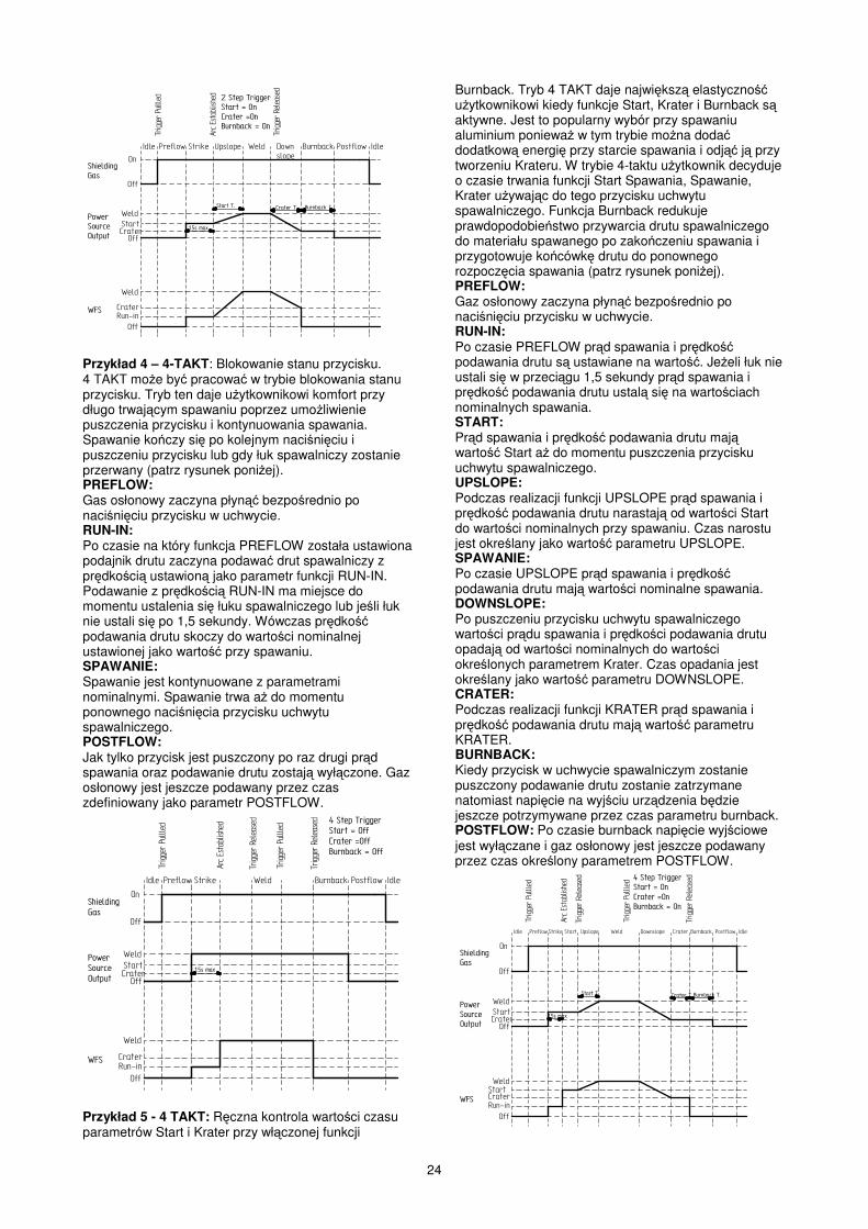
24
��
���
���
���
����
����
����
�����������
�����������������
!�
���� ������ ������ ���� ������� ������������ �����
���������������
����������������
��������������������"����������"��$���%����"���
�&����'
������� ������
�����
$���%��������������
!��������
"�����
���������
"�����
Przykład 4 – 4-TAKT: Blokowanie stanu przycisku. 4 TAKT mo�e by� pracowa� w trybie blokowania stanu przycisku. Tryb ten daje u�ytkownikowi komfort przy długo trwaj�cym spawaniu poprzez umo�liwienie puszczenia przycisku i kontynuowania spawania. Spawanie ko�czy si� po kolejnym naci�ni�ciu i puszczeniu przycisku lub gdy łuk spawalniczy zostanie przerwany (patrz rysunek poni�ej). PREFLOW: Gas osłonowy zaczyna płyn�� bezpo�rednio po naci�ni�ciu przycisku w uchwycie. RUN-IN: Po czasie na który funkcja PREFLOW została ustawiona podajnik drutu zaczyna podawa� drut spawalniczy z pr�dko�ci� ustawion� jako parametr funkcji RUN-IN. Podawanie z pr�dko�ci� RUN-IN ma miejsce do momentu ustalenia si� łuku spawalniczego lub je�li łuk nie ustali si� po 1,5 sekundy. Wówczas pr�dko�� podawania drutu skoczy do warto�ci nominalnej ustawionej jako warto�� przy spawaniu. SPAWANIE: Spawanie jest kontynuowane z parametrami nominalnymi. Spawanie trwa a� do momentu ponownego naci�ni�cia przycisku uchwytu spawalniczego. POSTFLOW: Jak tylko przycisk jest puszczony po raz drugi pr�d spawania oraz podawanie drutu zostaj� wył�czone. Gaz osłonowy jest jeszcze podawany przez czas zdefiniowany jako parametr POSTFLOW.
��
���
���
���
����
����
����
�����������
�����������������
!�
���� ������ ������ ���� ������� ����
�������� �����
���������������
���������������� (�������������
������"��##�������"�##$���%����"��##
�&����'
������
�����"�����
"�����
�������� �����
����������������
Przykład 5 - 4 TAKT: R�czna kontrola warto�ci czasu parametrów Start i Krater przy wł�czonej funkcji
Burnback. Tryb 4 TAKT daje najwi�ksz� elastyczno�� u�ytkownikowi kiedy funkcje Start, Krater i Burnback s� aktywne. Jest to popularny wybór przy spawaniu aluminium poniewa� w tym trybie mo�na doda� dodatkow� energi� przy starcie spawania i odj�� j� przy tworzeniu Krateru. W trybie 4-taktu u�ytkownik decyduje o czasie trwania funkcji Start Spawania, Spawanie, Krater u�ywaj�c do tego przycisku uchwytu spawalniczego. Funkcja Burnback redukuje prawdopodobie�stwo przywarcia drutu spawalniczego do materiału spawanego po zako�czeniu spawania i przygotowuje ko�cówk� drutu do ponownego rozpocz�cia spawania (patrz rysunek poni�ej). PREFLOW: Gaz osłonowy zaczyna płyn�� bezpo�rednio po naci�ni�ciu przycisku w uchwycie. RUN-IN: Po czasie PREFLOW pr�d spawania i pr�dko�� podawania drutu s� ustawiane na warto��. Je�eli łuk nie ustali si� w przeci�gu 1,5 sekundy pr�d spawania i pr�dko�� podawania drutu ustal� si� na warto�ciach nominalnych spawania. START: Pr�d spawania i pr�dko�� podawania drutu maj� warto�� Start a� do momentu puszczenia przycisku uchwytu spawalniczego. UPSLOPE: Podczas realizacji funkcji UPSLOPE pr�d spawania i pr�dko�� podawania drutu narastaj� od warto�ci Start do warto�ci nominalnych przy spawaniu. Czas narostu jest okre�lany jako warto�� parametru UPSLOPE. SPAWANIE: Po czasie UPSLOPE pr�d spawania i pr�dko�� podawania drutu maj� warto�ci nominalne spawania. DOWNSLOPE: Po puszczeniu przycisku uchwytu spawalniczego warto�ci pr�du spawania i pr�dko�ci podawania drutu opadaj� od warto�ci nominalnych do warto�ci okre�lonych parametrem Krater. Czas opadania jest okre�lany jako warto�� parametru DOWNSLOPE. CRATER: Podczas realizacji funkcji KRATER pr�d spawania i pr�dko�� podawania drutu maj� warto�� parametru KRATER. BURNBACK: Kiedy przycisk w uchwycie spawalniczym zostanie puszczony podawanie drutu zostanie zatrzymane natomiast napi�cie na wyj�ciu urz�dzenia b�dzie jeszcze potrzymywane przez czas parametru burnback. POSTFLOW: Po czasie burnback napi�cie wyj�ciowe jest wył�czane i gaz osłonowy jest jeszcze podawany przez czas okre�lony parametrem POSTFLOW.
��
���
���
���
����
����
����
�����������
�����������������
!�
���� ������������ ���� ������� ����
�������� �����
���������������
���������������� (�������������
������"����������"��$���%����"���
�&����'
������
�����
$���%��������������
"�����
���������
"�����
�������� �����
����������������
����� ������� !�������� "�����
�����
25
MENU KONFIGURACJI URZDZENIA Menu te pozwala na dost�p do parametrów konfiguruj�cych prac� urz�dzenia. Parametry te s� parametrami u�ytkownika w zasadzie ustawiane tylko przy instalacji urz�dzenia. Parametry konfiguracji mo�na pogrupowa� nast�puj�co: P.1 do P.99 Niezabezpieczone Parametry (zawsze ustawialne). P.101 do P.199 Parametery Diagnostyczne (zawsze Tylko Do Odczytu). P.501 do P.599 Parametery Zabezpieczone (dost�pne tylko przez aplikacj� komputerow�). Aby wej�� do Menu Konfiguracji Urz�dzenia nale�y naci�n�� jednocze�nie dwa przyciski. Nie mo�na wej�� do Menu w czasie spawania. Zmiana warto�ci migaj�cego parametru nast�puje poprzez obracanie dolnego enkodera. Po zmianie parametru nale�y nacisn�� prawy przycisk dla jego zapami�tania. Naci�ni�cie lewego przycisku anuluje nastawion� warto��. Aby wyj�� z Menu nacisn�� dwa przycisku jednocze�nie. Równie� po 1 minucie braku aktywno�ci nast�pi wyj�cie z Menu. Niezabezpieczone parametry P.0 Nacisn�� lewy przycisk aby wyj�� z Menu. P.1 Jednostki pr�dko�ci podawania drutu Metryczne = m/min Calowe = in/min P.2 Tryb wy�wietlania Amps = Lewy wy�wietlacz pokazuje nat��enie pr�cu podczas spawania. WFS = Lewy wy�wietlacz pokazuje pr�dko�� podawania drutu podczas spawania. P.4 Przywołanie pami�ci przycisku Enable = Wybór pami�ci 2 do 6 poprzez szybkie naci�ni�cia przycisku uchwytu. Opcja ta jest dost�pna, gdy panel podwójny - procedura/pami�� jest zainstalowany. Aby przywoła� pami�� za pomoc� przycisku nale�y tyle razy szybko nacisn�� przycisk, ile wynosi numer pami�ci, któr� chcemy przywoła�. Przywołanie jest mo�liwe tylko w stanie jałowym urz�dzenia. Disable = Wybór pami�ci jest mo�liwy tylko przyciskami na panelu podwójnym – procedura/pami��. P.5 Zmiana Procedur Przyciskiem Uchwytu Quick Trigger = Pozwala na przeł�czanie pomi�dzy procedur� A i B podczas spawania. Wymagany jest panel podwójny – procedura/pami��. Aby zastosowa�: Wybra� procedur� “GUN” na panelu pami��. Rozpocz�� spawanie poprzez naci�ni�cie przycisku. Urz�dzenie b�dzie spawało ustawieniami procedury A. Podczas spawania szybko zwolni� i ponownie nacisn�� przycisk uchwytu. Urz�dzenie przeł�czy si� na ustawienia procedury B. Zwolni� przycisk aby zatrzyma� spawanie. Przy nast�pnym spawaniu urz�dzenie znowu rozpocznie z ustawieniami procedury A. Integral TrigProc = U�y� Integral Trigger + Procedure Switch przy zastosowaniu uchwytu Lincoln Dual Schedule. Przy pracy 2-krokowej urz�dzenie działa identycznie jak przy wyborze External Switch. Dla pracy w trybie 4-krokowym: Wybra� procedur� “GUN” na panelu pami�ci. Rozpocz�� spawanie naciskaj�c przycisk na uchwycie. Urz�dzenie zacznie spawanie według ustawie� procedury A.
Podczas spawanie szybko pu�ci� I nacisn�� przycisk. Urz�dzenie przeł�czy si� na ustawienia procedury B. Pu�ci� przycisk aby zatrzyma� spawanie. Przy nast�pnym spawaniu urz�dzenie rozpocznie znowu ustawieniami procedury A. External Switch = Wybór Dual Procedure mo�liwy jest tylko przyciskiem na panelu pami�ci lub uchwytem dual procedure (domy�lnie). P.6 Uchwyt Push Pull, Ustawianie Parametru Zwłoka Parametr Zwłoka kontroluje opó�nienie momentu obrotowego silnika Push-Pull gdy u�ywany jest uchwyt push-pull. Podajnik drutu jest fabrycznie ustawiony na - bez zwłoki. O ile nie ma znacznego oporu na podawanym drucie parametr Zwłoka mo�e by� zredukowany na tyle, aby zapobiega� zakleszczaniu si� drutu. Jakkolwiek, mała warto�� parametru Zwłoka mo�e powoda� opó�nienie motoru podczas spawania i przypalanie drutu do ko�cówki pr�dowej. Je�eli pojawia si� zakleszczanie drutu sprawdzi� najpierw inne przyczyny przed zmian� parametru Zwłoka. Domy�lna warto�� parametru to 75 z mo�liw� zmian� w zakresie 5-100. Aby ustawi� parametr Zwłoka: Pokr�tłem VOLTS/TRIM ustawi� parametr Zwłoka. Zwi�kszenie spowoduje wzrost momentu obrotowego silnika, zmniejszenie zmniejszy moment obrotowy silnika. Nie zwi�ksza� moment obrotowy wi�cej ni� to konieczne. Wysoka warto�� parametru Zwłoka mo�e powodowa� zakleszczanie si� drutu, a niska warto�� mo�e powodowa� przypalanie drutu do ko�cówki pr�dowej. Nacisn�� prawy przycisk aby zachowa� nowe ustawienia. P.7 Ustawianie Offsetu Uchwytu Push Pull Kalibracja offsetu uchwytu push-pull ustawia pr�dko�� silnika pull. Procedura kalibracji powinna by� przeprowadzona tylko wtedy, gdy inne mo�liwe korekty nie rozwi�zuj� problemu podawania drutu. Miernik obrotów jest konieczny aby przeprowadzi� kalibracj�. Dla jej przeprowadzenia nale�y: Zwolni� rami� dociskowe na obydwu podajnikach drutu (Pull i Push). Ustawi� pr�dko�� podawania drutu na 200 rpm. Usun�� drut z podajnika drutu pull. Trzyma� miernik obrotów na rolce podajnika pull. Nacisn�� przycisk na uchwycie push-pull. Zmierzy� pr�dko�� obrotow� podajnika pull. Pr�dko�� powinna mie�ci� si� w zakresie 115-125 rpm. Je�eli oka�e si� to konieczne zmniejszy� ustawienie kalibracji aby zwolni� podajnik pull lub zwi�kszy� ustawienie aby przy�pieszy� podajnik. Zakres kalibracji wynosi od -30 do +40 z warto�ci� domy�ln� 0. Nacisn�� prawy przycisk aby zachowa� nowe ustawienia. P.8 Kontrola Gazu TIG (Dwa Ustawienia) 1. "Valve (manual)", wewn�trzny zawór nie działa podczas spawania TIG. Przepływ gazu jest r�cznie kontrolowany przez zewn�trzny zawór. 2. "Solenoid (auto)", wewn�trzny zawór wł�czy I wył�czy si� automatycznie podczas spawania TIG I tak: Czas Preflow nie b�dzie dost�pny z interfejsu u�ytkownika. Czas Postflow b�dzie dost�pny z interfejsu u�ytkownika i mo�e mie� warto�� od OFF (0 sekundy) do 10.0. Czas Postflow jest utrzymywany przy przeł�czaniu trybów spawania mi�dzy MIG i TIG. Kiedy wł�czenie wył�czenie urz�dzenia jest kontrolowane przez prawy enkoder. Przepływ gazu nast�pi dopiero
26
gdy elektroda dotknie materiału i zako�czy si� po czasie Postflow od momentu przerwania łuku. P.9 Opó�nienie Krateru U�y� opó�nienie krateru aby przej�� sekwencj� tworzenia krateru przy spawaniu punktowym punkt za punktem. Je�eli przycisk jest puszczony zanim upłynie czas opó�nienia krateru wówczas sekwencja tworzenia krateru jest pomijana. Je�eli przycisk jest puszczony po, sekwencja tworzenia krateru funkcjonuje normalnie. Warto�ci = = OFF (0) do 10.0 sekundy (OFF jest warto�ci� domy�ln�). P.11 Ustawienie Zegarów Menu te jest u�ywane do ustawiania czasów dla „Zbocza”, „Opadania”, „Ponowny Łuk”. Nacisn�� prawy przycisk aby wej�� do menu ustawiania zegarów. Nast�pnie dolnym enkoderem nastawi� na zegar, który chcemy ustawi�. Nacisn�� prawy przycisk. Encoderem ustawi� ��dany czas dla zegara. Nacisn�� lewy przycisk dla zapami�tania warto�ci. Czynno�ci powtórzy� dla ka�dego zegara, który chcemy ustawi�. Na zako�czenie jeszcze raz nacisn�� lewy przycisk aby wyj�� z menu. P.12 Opcje Traktora Menu te jest u�ywane do zmiany parametrów traktora wł�czaj�c w to opcje startu i ko�ca. Nacisn�� prawy przycisk aby wej�� w menu Opcje Traktora I obraca� encoder aby wybra� opcje startu lub ko�ca. Nacisn�� prawy przycisk aby zaakceptowa� opcj�. Nacisn�� lewy przycisk aby ustawi� opcj� i wyj�� z ustawiania opcji. Obraca� enkoder dla wybrania nast�pnej opcji lub nacisn�� lewy przycisk aby opu�ci� menu. P.13 Ustawianie Arc Force Ten parametr pozwala na ustawienie warto�ci Arc Force dla Startu, Spawania i Krateru. Nacisn�� prawy przycisk aby wej�� do menu i obraca� enkoderem aby wybra� mi�dzy Startem, Spawaniem czy Kraterem. Nacisn�� prawy przycisk i nast�pnie enkoderem wybra� ��dan� warto��. Nacisn�� lewy przycisk aby zapami�ta� warto�� i wyj�� z opcji. Kontynuowa� dla ustawienia Arc Force dla kolejnych stanów, nast�pnie nacisn�� lewy przycisk aby wyj�� z menu. P.14 Resetowanie Wagi Drutu Ten parametr pojawia si� tylko z systemem u�ywaj�cego Monitorowania Produkcji. U�y� tego parametru aby zresetowa� pocz�tkow� warto�� wagi drutu. P.16 Pokr�tło Uchwytu Push-Pull Potencjometr uchwytu dost�pny = Pr�dko�� podawania drutu jest zawsze kontrolowana przez potencjometr na uchwycie push-pull (domy�lnie). Potencjometr uchwytu zablokowany = Pr�dko�� podawania drutu jest zawsze kontrolowana przez lewy encoder na podajniku. Gun Pot Proc A = Gdy aktywna jest procedura A pr�dko�� podawania drutu jest ustawiana przez potencjometr uchwytu push-pull. Gdy aktywna jest procedura B pr�dko�� podawania drutu jest ustawiana przez lewy encoder na podajniku. P.25 Konfiguracja D�ojstika Pewne wersje uchwytów spawalniczych posiadaj� d�ojstik aby umo�liwi� u�ytkownikowi zmian� ró�nych parametrów spawania przy uchwycie, a nie na podajniku. P.25 mo�e by� u�yte do zmiany zachowania d�ojstika. We wszystkich konfiguracjach poło�enia góra-dół d�ojstika zmienia pr�dko�� podawania drutu.
Poprzez P.25 mo�na zmieni� sposób zachowania si� pozycji lewo-prawo d�ojstika. Kiedy P.25 jest ustawione na “WFS/Trim”, lewe i prawe poło�enie d�ojstika ustawia napi�cie łuku lub w trybie STT pr�d bazy. Kiedy P.25 jest ustawione na “Memory+Trim”, lewe I prawe poło�enie d�ojstika wybiera numer pami�ci w stanie jałowym lub napi�cie łuku lub w SST pr�d bazy podczas spawania. Kiedy P.25 jest ustawione na “Procedure A/B”, lewe i prawe poło�enie d�ojstika wybiera procedur� A lub B. Lewe poło�enie wybiera procedur� A, prawe procedur� B. PARAMETRY DIAGNOSTYCZNE P.80 Pomiar na wyj�ciu U�ywa� tego parametru tylko dla celów diagnostycznych. Gdy urz�dzenie jest ponownie zał�czone P.80 jest automatycznie resetowane na warto�� False. False = Pomiar jest okre�lony poprzez poło�enie przeł�cznika DIP w �ródle. True = Pomiar jest dokonywany na wyj�ciu �ródła i poło�enie przeł�cznika DIP jest ignorowane. P.99 Poka� Tryby Testowe W tablicach spawania s� zawarte specjalne tryby testowe dla testowania i serwisu urz�dze�. Ustawi� na „YES” aby wy�wietli� wszystkie tryby testowe. Po wył�czeniu urz�dzenia parametr automatycznie wraca do pozycji “NO”. P.100 Przegl�d Diagnostyczny Diagnostyka jest u�ywana tylko przy serwisowaniu urz�dzenia PowerWave. Yes = pokazuje od P.101 do P.500 w menu SETUP. No = tylko od P.0 do P.100 jest pokazane w menu SETUP. P.101 Event Logs Nacisn�� prawy przycisk, aby zobaczy� Event Logs. Obraca� enkoderem a� do wy�wietlenia po��danego parametru. Nast�pnie ponownie nacisn�� prawy przycisk. Pojawi� si� ró�ne informacje na temat wybranego parametru. Nacisn�� lewy przycisk aby wyj�� z opcji. P.102 Fatal Logs Nacisn�� prawy przycisk, aby zobaczy� Fatal Logs. Obraca� enkoderem aby wybra� moduł do przeczytania i nacisn�� prawy przycisk. Pojawi� si� ró�ne informacje na temat krytycznego modułu. Nacisn�� lewy przycisk aby wyj�� z opcji. P.103 Wersja Programu Nacisn�� prawy przycisk aby zobaczy� powy�szy parametr. Obraca� encoderem aby wybra� moduł, którego ma dotyczy�. Nacisn�� prawy przycisk aby wy�wietli� ��dany parametr. Nacisn�� lewy przycisk aby wyj�� z opcji. P.104 Wersja Urz�dzenia Nacisn�� prawy przycisk aby zobaczy� powy�szy parametr. Obraca� encoderem aby wybra� moduł, którego ma dotyczy�. Nacisn�� prawy przycisk aby wy�wietli� ��dany parametr. Nacisn�� lewy przycisk aby wyj�� z opcji. P.105 Wersja Programów Spawania
27
Nacisn�� prawy przycisk aby zobaczy� wersj� programów spawania. Nacisn�� lewy przycisk aby wyj�� z opcji. P.106 Address IP Nacisn�� prawy przycisk aby zobaczy� adres IP je�eli płytka sieciowa jest zainstalowana w urz�dzeniu. Je�eli płytka nie jest zainstalowana zostanie wy�wietlone "No Enet Found". Nacisn�� lewy przycisk aby wyj�� z opcji. P.107 �ródło Mocy Nacisn�� prawy przycisk aby zobaczy� typ �ródła mocy. Nacisn�� lewy przycisk aby wyj�� z opcji. Konserwacja
UWAGA W celu dokonania jakichkolwiek napraw lub czynno�ci konserwacyjnych zaleca si� kontakt z najbli�szym serwisem lub firm� Lincoln Electric. Dokonywanie napraw przez osoby lub firmy nieposiadaj�ce autoryzacji spowoduje utrat� praw gwarancyjnych. Cz�stotliwo�� wykonywania czynno�ci konserwacyjnych mo�e ró�ni� si� w zale�no�ci od �rodowiska, w jakim urz�dzenie pracuje. Jakiekolwiek zauwa�one uszkodzenia powinny by� natychmiastowo zgłaszane. Konserwacja podstawowa Sprawdza� stan izolacji i poł�cze� kabli spawalniczych i przewodu zasilaj�cego. Usuwa� odpryski z dyszy gazowej uchwytu spawalniczego. Rozpryski mog� przenosi� si� z gazem osłonowym do łuku. Sprawdza� stan uchwytu spawalniczego. Wymienia� go, je�li to konieczne. Sprawdza� stan i działanie wentylatora chłodz�cego. Utrzymywa� czyste otwory wlotu i wylotu powietrza chłodz�cego. Konserwacja okresowa Wykonywa� konserwacj� podstawow� oraz, dodatkowo: Utrzymywa� urz�dzenie w czysto�ci. Wykorzystuj�c strumie� suchego powietrza (pod niskim ci�nieniem) usun�� kurz z cz��ci zewn�trznych obudowy i z wn�trza spawarki. Sprawdzi� stan wszystkich styków elektrycznych i poprawi�, je�li jest taka konieczno��. Sprawdza� i dokr�ca� wszystkie �ruby.
UWAGA Sie� zasilaj�ca musi by� odł�czona od urz�dzenia przed ka�d� czynno�ci� konserwacyjn� i serwisow�. Po ka�dej naprawie wykona� odpowiednie sprawdzenie w celu zapewnienia bezpiecze�stwa u�ytkowania.
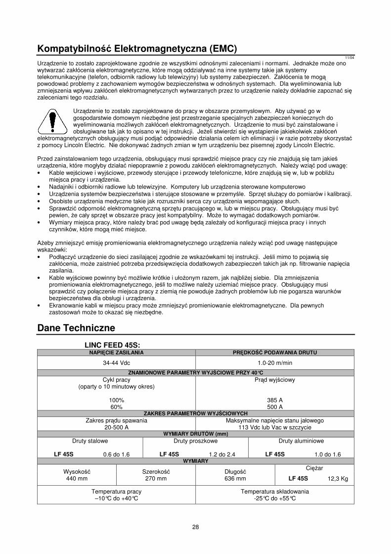
28
Kompatybilno� Elektromagnetyczna (EMC) 11/04
Urz�dzenie to zostało zaprojektowane zgodnie ze wszystkimi odno�nymi zaleceniami i normami. Jednak�e mo�e ono wytwarza� zakłócenia elektromagnetyczne, które mog� oddziaływa� na inne systemy takie jak systemy telekomunikacyjne (telefon, odbiornik radiowy lub telewizyjny) lub systemy zabezpiecze�. Zakłócenia te mog� powodowa� problemy z zachowaniem wymogów bezpiecze�stwa w odno�nych systemach. Dla wyeliminowania lub zmniejszenia wpływu zakłóce� elektromagnetycznych wytwarzanych przez to urz�dzenie nale�y dokładnie zapozna� si� zaleceniami tego rozdziału.
Urz�dzenie to zostało zaprojektowane do pracy w obszarze przemysłowym. Aby u�ywa� go w gospodarstwie domowym niezb�dne jest przestrzeganie specjalnych zabezpiecze� koniecznych do wyeliminowania mo�liwych zakłóce� elektromagnetycznych. Urz�dzenie to musi by� zainstalowane i obsługiwane tak jak to opisano w tej instrukcji. Je�eli stwierdzi si� wyst�pienie jakiekolwiek zakłóce�
elektromagnetycznych obsługuj�cy musi podj�� odpowiednie działania celem ich eliminacji i w razie potrzeby skorzysta� z pomocy Lincoln Electric. Nie dokonywa� �adnych zmian w tym urz�dzeniu bez pisemnej zgody Lincoln Electric. Przed zainstalowaniem tego urz�dzenia, obsługuj�cy musi sprawdzi� miejsce pracy czy nie znajduj� si� tam jakie� urz�dzenia, które mogłyby działa� niepoprawnie z powodu zakłóce� elektromagnetycznych. Nale�y wzi�� pod uwag�: • Kable wej�ciowe i wyj�ciowe, przewody steruj�ce i przewody telefoniczne, które znajduj� si� w, lub w pobli�u
miejsca pracy i urz�dzenia. • Nadajniki i odbiorniki radiowe lub telewizyjne. Komputery lub urz�dzenia sterowane komputerowo • Urz�dzenia systemów bezpiecze�stwa i steruj�ce stosowane w przemy�le. Sprz�t słu��cy do pomiarów i kalibracji. • Osobiste urz�dzenia medyczne takie jak rozruszniki serca czy urz�dzenia wspomagaj�ce słuch. • Sprawdzi� odporno�� elektromagnetyczn� sprz�tu pracuj�cego w, lub w miejscu pracy. Obsługuj�cy musi by�
pewien, �e cały sprz�t w obszarze pracy jest kompatybilny. Mo�e to wymaga� dodatkowych pomiarów. • Wymiary miejsca pracy, które nale�y bra� pod uwag� b�d� zale�ały od konfiguracji miejsca pracy i innych
czynników, które mog� mie� miejsce. A�eby zmniejszy� emisj� promieniowania elektromagnetycznego urz�dzenia nale�y wzi�� pod uwag� nast�puj�ce wskazówki: • Podł�czy� urz�dzenie do sieci zasilaj�cej zgodnie ze wskazówkami tej instrukcji. Je�li mimo to pojawi� si�
zakłócenia, mo�e zaistnie� potrzeba przedsi�wzi�cia dodatkowych zabezpiecze� takich jak np. filtrowanie napi�cia zasilania.
• Kable wyj�ciowe powinny by� mo�liwie krótkie i uło�onym razem, jak najbli�ej siebie. Dla zmniejszenia promieniowania elektromagnetycznego, je�li to mo�liwe nale�y uziemia� miejsce pracy. Obsługuj�cy musi sprawdzi� czy poł�czenie miejsca pracy z ziemi� nie powoduje �adnych problemów lub nie pogarsza warunków bezpiecze�stwa dla obsługi i urz�dzenia.
• Ekranowanie kabli w miejscu pracy mo�e zmniejszy� promieniowanie elektromagnetyczne. Dla pewnych zastosowa� mo�e to okaza� si� niezb�dne.
Dane Techniczne
LINC FEED 45S: NAPI�CIE ZASILANIA PR�DKO�� PODAWANIA DRUTU
34-44 Vdc 1.0-20 m/min
ZNAMIONOWE PARAMETRY WYJ�CIOWE PRZY 40°C Cykl pracy
(oparty o 10 minutowy okres)
100% 60%
Pr�d wyj�ciowy
385 A 500 A
ZAKRES PARAMETRÓW WYJ�CIOWYCH Zakres pr�du spawania
20-500 A Maksymalne napi�cie stanu jałowego
113 Vdc lub Vac w szczycie WYMIARY DRUTÓW (mm)
Druty stalowe
Druty proszkowe Druty aluminiowe
LF 45S 0.6 do 1.6 LF 45S 1.2 do 2.4 LF 45S 1.0 do 1.6 WYMIARY
Wysoko�� 440 mm
Szeroko�� 270 mm
Długo�� 636 mm
Ci��ar
LF 45S 12,3 Kg
Temperatura pracy –10°C do +40°C
Temperatura składowania -25°C do +55°C

29
Spare Parts, Parti di Ricambio, Ersatzteile, Lista de Piezas de Recambio, Pièces de Rechange, Deleliste, Reserve Onderdelen, Reservdelar, Wykaz Cz��ci Zamiennych, Varaosaluettelo
12/05 Part List reading instructions • Do not use this part list for a machine if its code number is not listed. Contact the Lincoln Electric Service Department for any code number not
listed. • Use the illustration of assembly page and the table below to determine where the part is located for your particular code machine. • Use only the the parts marked "X" in the column under the heading number called for in the assembly page (# indicate a change in this printing). Parti di Ricambio: istruzioni per la lettura • Non utilizzare questa lista se il code della macchina non è indicato. Contattare l’Assistenza Lincoln Electric per ogni code non compreso. • Utilizzare la figura della pagina assembly e la tabella sotto riportata per determinare dove la parte è situata per il code della vostra macchina. • Usare solo le parti indicate con "X" nella colonna sotto il numero richiamato nella pagina assembly (# indica un cambio in questa revisione). Hinweise zur Verwendung der Ersatzteillisten • Verwenden Sie diese Ersatzteilliste nur für die Geräte, deren Code Nummer in dieser Liste aufgeführt sind. Fehlt die Code-Nummer, wenden Sie
sich bitte in diesem Fall an die Firma Lincoln. • Bestimmen Sie mit Hilfe der Zusammenstellungszeichnung (assembly page), der Stückliste und der Code Nummer Ihres Geräts, an welcher Stelle
sich das jeweilige Ersatzteil befindet. • Ermitteln Sie zunächst mit Hilfe der assembly page die für die Code Nummer Ihres Geräts gültige Index-Spaltennummer, und wählen Sie
anschließend nur die Ersatzteile aus, die in dieser Spalte mit einem "X" markiert sind (das Zeichen # weist auf eine Änderung hin). Lista de piezas de recambio: instrucciones • No utilizar esta lista de piezas de recambio, si el número de code no está indicado. Contacte con el Dpto. de Servicio de Lincoln Electric para
cualquier número de code no indicado. • Utilice el dibujo de la página de ensamblaje (assembly page) y la tabla para determinar donde está localizado el número de code de su máquina. • Utilice sólo los recambios marcados con "X" de la columna con números según página de ensamblaje (# indica un cambio en esta revisión). Comment lire cette liste de pièces détachées • Cette liste de pièces détachées ne vaut que pour les machines dont le numéro de code est listé ci-dessous. Dans le cas contraire, contacter le
Département Pièces de Rechange. • Utiliser la vue éclatée (assembly page) et le tableau de références des pièces ci-dessous pour déterminer l'emplacement de la pièce en fonction du
numéro de code précis de la machine. • Ne tenir compte que des pièces marquées d'un "X" dans la colonne de cette vue éclatée (# Indique un changement). Instruksjon for deleliste • Ikke bruk denne delelisten hvis code nummeret for maskinen ikke står på listen. Kontakt Lincoln Electric Serviceavd. for maskiner med code
utenfor listen. • Bruk sprengskissen og pos. nr. på assembly page nedenfor for å finne de riktige delene til din maskin. • Bruk kun de delene som er merket med "X" i den kolonnen som det henvises til på siden med assembly page (# indikerer endring). Leessinstructie Onderdelenlijst • Gebruik deze onderdelenlijst niet voor machines waarvan de code niet in deze lijst voorkomt. Neem contact op met de dichtstbijzijnde Lincoln
dealer wanneer het code nummer niet vermeld is. • Gebruik de afbeelding van de assembly page en de tabel daaronder om de juiste onderdelen te selecteren in combinatie met de gebruikte code. • Gebruik alleen de onderdelen die met een "X" gemerkt zijn in de kolom onder het model type op de assembly page (# betekent een wijziging in het
drukwerk). Instruktion för reservdelslistan • Använd inte denna lista för en maskin vars Code No inte är angivet i listan. Kontakta Lincoln Electric’s serviceavdelning för Code No som inte finns
i listan. • Använd sprängskisserna på Assembly Page och tillhörande reservdelslista för att hitta delar till din maskin. • Använd endast delar markerade med "X" i kolumnen under den siffra som anges för aktuellt Code No på sidan med Assembly Page (# Indikerar en
ändring i denna utgåva). Wykaz cz��ci dotycz�cych instrukcji • Nie u�ywa� tej cz��ci wykazu dla maszyn, których kodu (code) nie ma na li�cie. Skontaktuj si� z serwisem je�eli numeru kodu nie ma na li�cie. • U�yj ilustracji monta�u (assembly page) i tabeli poni�ej aby okresli� poło�enie cz��ci dla urz�dzenia z konkretnym kodem (code). • U�yj tylko cz�ci z oznaczeniem "X" w kolumnie pod numerem głównym przywołuj�cym stron� (assembly page) z indeksem modelu (# znajd�
zmiany na rysunku). Osaluettelo, lukuohje • Älä käytä tätä osaluetteloa koneeseen, jonka koodinumero ei ole listassa. Ota yhteyttä Lincoln Electric huolto-osastoon mistä tahansa koodista,
joka ei ole listassa. • Käytä asennuskuvaa ja alla olevaa taulukkoa määrittääksesi, missä osa sijaitsee. • Käytä vain osia, jotka on merkitty "X":llä asennussivua ilmoittavassa sarakkeessa (# ilmoittaa muutoksesta tässä painoksessa).
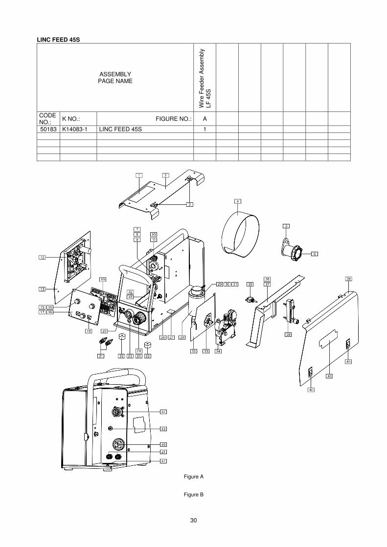
30
LINC FEED 45S
ASSEMBLY PAGE NAME
Wire
Fee
der A
ssem
bly
LF 4
5S
CODE NO.: K NO.: FIGURE NO.: A
50183 K14083-1 LINC FEED 45S 1
Figure A
Figure B
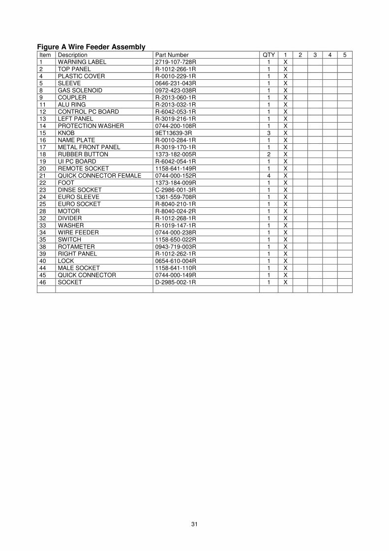
31
Figure A Wire Feeder Assembly Item Description Part Number QTY 1 2 3 4 5 1 WARNING LABEL 2719-107-728R 1 X 2 TOP PANEL R-1012-266-1R 1 X 4 PLASTIC COVER R-0010-229-1R 1 X 5 SLEEVE 0646-231-043R 1 X 8 GAS SOLENOID 0972-423-038R 1 X 9 COUPLER R-2013-060-1R 1 X 11 ALU RING R-2013-032-1R 1 X 12 CONTROL PC BOARD R-6042-053-1R 1 X 13 LEFT PANEL R-3019-216-1R 1 X 14 PROTECTION WASHER 0744-200-108R 1 X 15 KNOB 9ET13639-3R 3 X 16 NAME PLATE R-0010-284-1R 1 X 17 METAL FRONT PANEL R-3019-170-1R 1 X 18 RUBBER BUTTON 1373-182-005R 2 X 19 UI PC BOARD R-6042-054-1R 1 X 20 REMOTE SOCKET 1158-641-149R 1 X 21 QUICK CONNECTOR FEMALE 0744-000-152R 4 X 22 FOOT 1373-184-009R 1 X 23 DINSE SOCKET C-2986-001-3R 1 X 24 EURO SLEEVE 1361-559-708R 1 X 25 EURO SOCKET R-8040-210-1R 1 X 28 MOTOR R-8040-024-2R 1 X 32 DIVIDER R-1012-268-1R 1 X 33 WASHER R-1019-147-1R 1 X 34 WIRE FEEDER 0744-000-238R 1 X 35 SWITCH 1158-650-022R 1 X 38 ROTAMETER 0943-719-003R 1 X 39 RIGHT PANEL R-1012-262-1R 1 X 40 LOCK 0654-610-004R 1 X 44 MALE SOCKET 1158-641-110R 1 X 45 QUICK CONNECTOR 0744-000-149R 1 X 46 SOCKET D-2985-002-1R 1 X
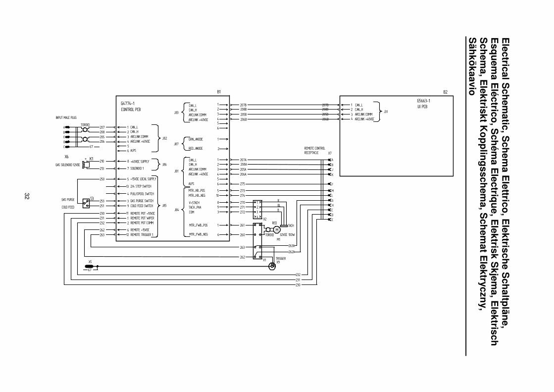
32
Electrical S
chematic, S
chema E
lettrico, Elektrische S
chaltpläne, E
squema E
léctrico, Schém
a Electrique, E
lektrisk Skjem
a, Elektrisch
Schem
a, Elektriskt K
opplingsschema, S
chemat E
lektryczny, S
ähkökaavio
& �
)*+
,
�-+�-(
�-��- �-�
./0
�,�1
�2�3�,
�,
�,+�,�
�,�
�,+
4& 4*�./.
*+
(
+
&
�+��+ �+�
�& �&+
�&�
�
��50�!//0
2���6./ �+
-
)
� +
� �7 8
��)
��,��&
�
(+
��-
4,
$$5.
�+(
�
��)2
��,2��&2
�
(+
��-2
��,$��&$
��)$��-$(--(9
��,$��&$��)$
(+�
��-$ &,,+9
8(��0���6��5:
��5/;�0�
�2;<5
2.�5;7���112.�5;7�8(��0�
�2;<3
8 &�0��5��25��6��5:
�=(���/��� ��3
�655=����5�� ��3
2���6./�� ��3��50�!//0�� ��3
./1��/�����8 ��0�
./1��/����� �/.
./1��/�������11
./1��/�8 &�0�
./1��/��./.�
2����5/;�0� ��0�
1�.<! $<���
1�.<! $<;/
��1�2�3<�32�8&�2�3
1�.<3$<;/1�.<3$<���
./0<2;�0/
.;<2;�0/
�2;<3
2.�5;7�8(��0�2.�5;7���11
�2;<5
>)�
>)(
>),
>)&
>)-
>)
>)+
+��0�� ��
��;�.�5���$
$
6���$
$�
;�6��125/��56
4-
1
./1��/���;�.�5
./�/��2�5/
�+�
�+ �+�
�,+2
�,�2
��.�0
��.�0
$
2
/
0
$
2
>
7
15
3�0/
�2;<3
2.�5;7�8(��0�2.�5;7���11
�2;<5�
(+
4
4�
>+ �2;<3
2.�5;7�8(��0�2.�5;7���11
�2;<5
�-&,&
25�� !
,&25��
,&
� ,-
,-
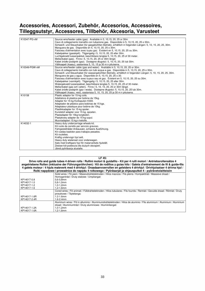
33
Accessories, Accessori, Zubehör, Accesorios, Accessoires, Tilleggsutstyr, Accessores, Tillbehör, Akcesoria, Varusteet K10347-PG-xM Source wire/feeder cable (gas). Available in 5, 10,15, 20, 25 or 30m.
Cavo di collegamento trainafilo con tubazione gas. Disponibile in 5, 10,15, 20, 25 o 30m. Schweiß- und Steuerkabel (für gasgekühlten Betrieb), erhältlich in folgenden Längen: 5, 10, 15, 20, 25, 30m. Manguera de gas. Disponible en 5, 10,15, 20, 25 o 30m. Faisceau d'alimentation avec tuyau gaz. Existent en 5, 10,15, 20, 25 ou 30m. Kabelpakker (gasskjølt). Tilgjengelig i 5, 10,15, 20, 25 eller 30m. Luchtgekoeld tussenpakket, beschikbare lengtes 5, 10,15, 20, 25 of 30 meter. Mellankabel (gas). Finns i 5, 10,15, 20, 25 or 30m längd. Kabel �ródło-podajnik (gaz). Dost�pne długo�ci: 5, 10,15, 20, 25 lub 30m. Välikaapeli (kaasu), saatavissa 5, 10, 15 ja 30 m:n pituisena.
K10349-PGW-xM Source wire/feeder cable (gas and water). Available in 5, 10,15, 20, 25 or 30m. Cavo di collegamento trainafilo con tubi acqua e gas. Disponibile in 5, 10,15, 20, 25 o 30m. Schweiß- und Steuerkabel (für wassergekühlten Betrieb), erhältlich in folgenden Längen: 5, 10, 15, 20, 25, 30m. Manguera de gas y agua. Disponible en 5, 10,15, 20, 25 o 30. Faisceau d'alimentation avec tuyaux eau et gaz. Existent en 5, 10,15, 20, 25 ou 30m. Kabelpakker (vannkjølt). Tilgjengelig i 5, 10,15, 20, 25 eller 30m. Watergekoeld tussenpakket, beschikbare lengtes 5, 10,15, 20, 25 of 30 meter. Mellankabel (gas och vatten). Finns i 5, 10, 15, 20, 25 or 30m längd. Kabel �ródło-podajnik (gaz i woda). Dostepne długo�ci: 5, 10,15, 20, 25 lub 30m. Välikaapeli (kaasu, vesi), saatavissa 5, 10, 15, 20, 25 ja 30 m:n pituisena.
K10158 Plastic adaptor for 15-kg coils. Adattatore di plastica per bobine da 15kg. Adapter für 15-kg-Korbspulen K300. Adaptador de plástico para bobinas de 15 kgs. Adaptateur plastique pour bobine de 15kg. Plastikkadapter for 15-kg spoler. Kunststof adapter voor 15 kg. spoelen. Plastadapter för 15kg korgbobin. Plastykowy adapter do 15-kg szpul. Muoviadapteri 15 kg:n keloille.
K14032-1 Heavy duty undercarriage wheels kit. Kit ruote da carrello per servizio gravoso. Fahrgestellräder-Anbausatz, schwere Ausführung. Kit ruedas bastidor para trabajos pesados. Kit roulettes. Kraftig undervogn hjul sett. Heavy duty wielenset voor onderwagen. Sats med kraftigare hjul för matarverkets hjulställ. Zestaw kół podwozia dla du�ych obci��e�. Järeä pyöräsarja alustalle.
LF 45: Drive rolls and guide tubes 4 driven rolls / Rullini motori & guidafilo - Kit per 4 rulli motori / Antriebsrollensätze 4
angetriebene Rollen (inklusive der Führungsröhrchen) / Kit de rodillos y guías hilo / Galets d'entrainement de fil & guide-fils 4 galets moteur / 4 hjuls mateverk med 4 drivhjul / Draadaanvoerrollen en geleiders 4 drivhjul / Drivhjulsatser 4 drivna hjul /
Rolki nap�dowe i prowadnice do nap�du 4 rolkowego / Pyöräsarjat ja ohjausputket 4 - pyörävetolaitteisiin KP14017-0.8 KP14017-1.0 KP14017-1.2 KP14017-1.6
Solid wires / Fili pieni / Massivdrahtelektroden / Hilos macizos / Fils pleins / Kompakttråd / Massieve draad / Homogentråd / Druty stalowe / Umpilangat: 0,6-0,8mm 0,8-1,0mm 1,0-1,2mm 1,2-1,6mm
KP14017-1.6R KP14017-2.4R
Cored wires / Fili animati / Fülldrahtelektroden / Hilos tubulares / Fils fourrés / Rørtråd / Gevulde draad / Rörtråd / Druty proszkowe / Täytelanga: 1.2-1.6mm 1.6-2.4mm
KP14017-1.2A KP14017-1.6A
Aluminum wires / Fili in alluminio / Aluminiumdrahtelektroden / Hilos de aluminio / Fils aluminium / Aluminium / Aluminium draad / Aluminiumtråd / Druty aluminiowe / Alumiinilangat: 1,0-1,2mm 1,2-1,6mm
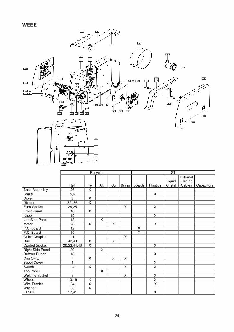
34
WEEE
Recycle ST
Ref. Fe Al. Cu Brass Boards Plastics Liquid Cristal
External Electric Cables Capacitors
Base Assembly 26 X Brake 5,6 X Cover 2 X Divider 32, 36 X Euro Socket 24,25 X X Front Panel 16 X Knob 15 X Left Side Panel 13 X Motor 28 X X X P.C. Board 12 X P.C. Board 19 X Quick Coupling 21 X Rail 42,43 X X Control Socket 20,23,44,46 X X Right Side Panel 39 X Rubber Button 18 X Gas Switch 7 X X X Spool Cover 4 X Switch 24 X X X Top Panel 2 X Welding Socket 8 X X Wheels 13,16 X X Wire Feeder 34 X X Washer 33 X Labels 17,41 X

35
MANUAL REVISIONS DO NOT PRINT THIS PAGE IN THE MANUAL. REV 0: • New edition. PRINT THIS MANUAL ACCORDINGLY WITH THE PROCEDURE DT0052.


![Squeeze - Singles [45s and Under]](https://img.pdfslide.net/doc/110x75/56d6bd5e1a28ab30168db5e3/squeeze-singles-45s-and-under.jpg)