Embed Size (px)
Citation preview

SP-125 PLUS
OPERATOR’S MANUAL
IM536-DMarch, 2001
Safety Depends on YouLincoln arc welding and cuttingequipment is designed and builtwith safety in mind. However, youroverall safety can be increased byproper installation ... and thought-ful operation on your part. DONOT INSTALL, OPERATE ORREPAIR THIS EQUIPMENTWITHOUT READING THISMANUAL AND THE SAFETYPRECAUTIONS CONTAINEDTHROUGHOUT. And, mostimportantly, think before you actand be careful.
For use with machine Code Numbers 10260, 10481,10685,10689,10690,10740
ISO 9001
CERTIFICATE NUMBER: 30273
Designed and Manufactured Under aQuality Program Certified byABS Quality Evaluations, Inc.to ISO 9001 Requirements.
QMSANSI RAB
• Sales and Service through Subsidiaries and Distributors Worldwide •
Cleveland, Ohio 44117-1199 U.S.A. TEL: 216.481.8100 FAX: 216.486.1751 WEB SITE: www.lincolnelectric.com
• World's Leader in Welding and Cutting Products •
Date of Purchase:Serial Number:Code Number:Model:Where Purchased:
Copyright © 2001 Lincoln Global Inc.
SP-125 PLUS
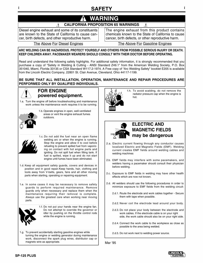
FOR ENGINEpowered equipment.
1.a. Turn the engine off before troubleshooting and maintenancework unless the maintenance work requires it to be running.
____________________________________________________1.b. Operate engines in open, well-ventilated
areas or vent the engine exhaust fumes outdoors.
____________________________________________________1.c. Do not add the fuel near an open flame
welding arc or when the engine is running.Stop the engine and allow it to cool beforerefueling to prevent spilled fuel from vaporiz-ing on contact with hot engine parts andigniting. Do not spill fuel when filling tank. Iffuel is spilled, wipe it up and do not startengine until fumes have been eliminated.
____________________________________________________1.d. Keep all equipment safety guards, covers and devices in
position and in good repair.Keep hands, hair, clothing andtools away from V-belts, gears, fans and all other movingparts when starting, operating or repairing equipment.
____________________________________________________
1.e. In some cases it may be necessary to remove safetyguards to perform required maintenance. Removeguards only when necessary and replace them when themaintenance requiring their removal is complete.Always use the greatest care when working near movingparts.
___________________________________________________1.f. Do not put your hands near the engine fan.
Do not attempt to override the governor oridler by pushing on the throttle control rodswhile the engine is running.
___________________________________________________1.g. To prevent accidentally starting gasoline engines while
turning the engine or welding generator during maintenancework, disconnect the spark plug wires, distributor cap ormagneto wire as appropriate.
iSAFETYi
ARC WELDING CAN BE HAZARDOUS. PROTECT YOURSELF AND OTHERS FROM POSSIBLE SERIOUS INJURY OR DEATH.KEEP CHILDREN AWAY. PACEMAKER WEARERS SHOULD CONSULT WITH THEIR DOCTOR BEFORE OPERATING.
Read and understand the following safety highlights. For additional safety information, it is strongly recommended that youpurchase a copy of “Safety in Welding & Cutting - ANSI Standard Z49.1” from the American Welding Society, P.O. Box351040, Miami, Florida 33135 or CSA Standard W117.2-1974. A Free copy of “Arc Welding Safety” booklet E205 is availablefrom the Lincoln Electric Company, 22801 St. Clair Avenue, Cleveland, Ohio 44117-1199.
BE SURE THAT ALL INSTALLATION, OPERATION, MAINTENANCE AND REPAIR PROCEDURES AREPERFORMED ONLY BY QUALIFIED INDIVIDUALS.
WARNING
Mar ‘95
ELECTRIC AND MAGNETIC FIELDSmay be dangerous
2.a. Electric current flowing through any conductor causes localized Electric and Magnetic Fields (EMF). Welding current creates EMF fields around welding cables and welding machines
2.b. EMF fields may interfere with some pacemakers, andwelders having a pacemaker should consult their physicianbefore welding.
2.c. Exposure to EMF fields in welding may have other healtheffects which are now not known.
2.d. All welders should use the following procedures in order tominimize exposure to EMF fields from the welding circuit:
2.d.1. Route the electrode and work cables together - Securethem with tape when possible.
2.d.2. Never coil the electrode lead around your body.
2.d.3. Do not place your body between the electrode andwork cables. If the electrode cable is on your right side, the work cable should also be on your right side.
2.d.4. Connect the work cable to the workpiece as close aspossible to the area being welded.
2.d.5. Do not work next to welding power source.
1.h. To avoid scalding, do not remove theradiator pressure cap when the engine ishot.
CALIFORNIA PROPOSITION 65 WARNINGS
Diesel engine exhaust and some of its constituentsare known to the State of California to cause can-cer, birth defects, and other reproductive harm.
The engine exhaust from this product containschemicals known to the State of California to causecancer, birth defects, or other reproductive harm.
The Above For Diesel Engines The Above For Gasoline Engines
SP-125 PLUS
iiSAFETYii
ARC RAYS can burn.4.a. Use a shield with the proper filter and cover
plates to protect your eyes from sparks andthe rays of the arc when welding or observingopen arc welding. Headshield and filter lensshould conform to ANSI Z87. I standards.
4.b. Use suitable clothing made from durable flame-resistantmaterial to protect your skin and that of your helpers fromthe arc rays.
4.c. Protect other nearby personnel with suitable, non-flammablescreening and/or warn them not to watch the arc nor exposethemselves to the arc rays or to hot spatter or metal.
ELECTRIC SHOCK cankill.3.a. The electrode and work (or ground) circuits
are electrically “hot” when the welder is on.Do not touch these “hot” parts with your bareskin or wet clothing. Wear dry, hole-free
gloves to insulate hands.
3.b. Insulate yourself from work and ground using dry insulation.Make certain the insulation is large enough to cover your fullarea of physical contact with work and ground.
In addition to the normal safety precautions, if weldingmust be performed under electrically hazardousconditions (in damp locations or while wearing wetclothing; on metal structures such as floors, gratings orscaffolds; when in cramped positions such as sitting,kneeling or lying, if there is a high risk of unavoidable oraccidental contact with the workpiece or ground) usethe following equipment:
• Semiautomatic DC Constant Voltage (Wire) Welder.• DC Manual (Stick) Welder.• AC Welder with Reduced Voltage Control.
3.c. In semiautomatic or automatic wire welding, the electrode,electrode reel, welding head, nozzle or semiautomaticwelding gun are also electrically “hot”.
3.d. Always be sure the work cable makes a good electricalconnection with the metal being welded. The connectionshould be as close as possible to the area being welded.
3.e. Ground the work or metal to be welded to a good electrical(earth) ground.
3.f. Maintain the electrode holder, work clamp, welding cable andwelding machine in good, safe operating condition. Replacedamaged insulation.
3.g. Never dip the electrode in water for cooling.
3.h. Never simultaneously touch electrically “hot” parts ofelectrode holders connected to two welders because voltagebetween the two can be the total of the open circuit voltageof both welders.
3.i. When working above floor level, use a safety belt to protectyourself from a fall should you get a shock.
3.j. Also see Items 6.c. and 8.
FUMES AND GASEScan be dangerous.5.a. Welding may produce fumes and gases
hazardous to health. Avoid breathing thesefumes and gases.When welding, keepyour head out of the fume. Use enoughventilation and/or exhaust at the arc to keep
fumes and gases away from the breathing zone. Whenwelding with electrodes which require specialventilation such as stainless or hard facing (seeinstructions on container or MSDS) or on lead orcadmium plated steel and other metals or coatingswhich produce highly toxic fumes, keep exposure aslow as possible and below Threshold Limit Values (TLV)using local exhaust or mechanical ventilation. Inconfined spaces or in some circumstances, outdoors, arespirator may be required. Additional precautions arealso required when welding on galvanized steel.
5.b. Do not weld in locations near chlorinated hydrocarbon vaporscoming from degreasing, cleaning or spraying operations.
The heat and rays of the arc can react with solvent vapors to form phosgene, a highly toxic gas, and other irritating products.
5.c. Shielding gases used for arc welding can displace air andcause injury or death. Always use enough ventilation,especially in confined areas, to insure breathing air is safe.
5.d. Read and understand the manufacturer’s instructions for thisequipment and the consumables to be used, including thematerial safety data sheet (MSDS) and follow youremployer’s safety practices. MSDS forms are available fromyour welding distributor or from the manufacturer.
5.e. Also see item 1.b. Mar ‘95
SP-125 PLUS
FOR ELECTRICALLYpowered equipment.
8.a. Turn off input power using the disconnectswitch at the fuse box before working onthe equipment.
8.b. Install equipment in accordance with the U.S. NationalElectrical Code, all local codes and the manufacturer’srecommendations.
8.c. Ground the equipment in accordance with the U.S. NationalElectrical Code and the manufacturer’s recommendations.
CYLINDER may explodeif damaged.7.a. Use only compressed gas cylinders
containing the correct shielding gas for theprocess used and properly operatingregulators designed for the gas and
pressure used. All hoses, fittings, etc. should be suitable forthe application and maintained in good condition.
7.b. Always keep cylinders in an upright position securelychained to an undercarriage or fixed support.
7.c. Cylinders should be located:• Away from areas where they may be struck or subjected tophysical damage.
• A safe distance from arc welding or cutting operations andany other source of heat, sparks, or flame.
7.d. Never allow the electrode, electrode holder or any otherelectrically “hot” parts to touch a cylinder.
7.e. Keep your head and face away from the cylinder valve outletwhen opening the cylinder valve.
7.f. Valve protection caps should always be in place and handtight except when the cylinder is in use or connected foruse.
7.g. Read and follow the instructions on compressed gascylinders, associated equipment, and CGA publication P-l,“Precautions for Safe Handling of Compressed Gases inCylinders,” available from the Compressed Gas Association1235 Jefferson Davis Highway, Arlington, VA 22202.
iiiSAFETYiii
Mar ‘95
WELDING SPARKS cancause fire or explosion.6.a. Remove fire hazards from the welding area.
If this is not possible, cover them to preventthe welding sparks from starting a fire.Remember that welding sparks and hot
materials from welding can easily go through small cracksand openings to adjacent areas. Avoid welding nearhydraulic lines. Have a fire extinguisher readily available.
6.b. Where compressed gases are to be used at the job site,special precautions should be used to prevent hazardoussituations. Refer to “Safety in Welding and Cutting” (ANSIStandard Z49.1) and the operating information for theequipment being used.
6.c. When not welding, make certain no part of the electrodecircuit is touching the work or ground. Accidental contactcan cause overheating and create a fire hazard.
6.d. Do not heat, cut or weld tanks, drums or containers until theproper steps have been taken to insure that such procedureswill not cause flammable or toxic vapors from substancesinside. They can cause an explosion even though they havebeen “cleaned”. For information, purchase “RecommendedSafe Practices for the Preparation for Welding and Cutting ofContainers and Piping That Have Held HazardousSubstances”, AWS F4.1 from the American Welding Society(see address above).
6.e. Vent hollow castings or containers before heating, cutting orwelding. They may explode.
6.f. Sparks and spatter are thrown from the welding arc. Wear oilfree protective garments such as leather gloves, heavy shirt,cuffless trousers, high shoes and a cap over your hair. Wearear plugs when welding out of position or in confined places.Always wear safety glasses with side shields when in awelding area.
6.g. Connect the work cable to the work as close to the weldingarea as practical. Work cables connected to the buildingframework or other locations away from the welding areaincrease the possibility of the welding current passingthrough lifting chains, crane cables or other alternate cir-cuits. This can create fire hazards or overheat lifting chainsor cables until they fail.
6.h. Also see item 1.c.
SP-125 PLUS
ivSAFETYiv
PRÉCAUTIONS DE SÛRETÉPour votre propre protection lire et observer toutes les instructionset les précautions de sûreté specifiques qui parraissent dans cemanuel aussi bien que les précautions de sûreté générales suiv-antes:
Sûreté Pour Soudage A L’Arc1. Protegez-vous contre la secousse électrique:
a. Les circuits à l’électrode et à la piéce sont sous tensionquand la machine à souder est en marche. Eviter toujourstout contact entre les parties sous tension et la peau nueou les vétements mouillés. Porter des gants secs et sanstrous pour isoler les mains.
b. Faire trés attention de bien s’isoler de la masse quand onsoude dans des endroits humides, ou sur un planchermetallique ou des grilles metalliques, principalement dans les positions assis ou couché pour lesquelles une grandepartie du corps peut être en contact avec la masse.
c. Maintenir le porte-électrode, la pince de masse, le câblede soudage et la machine à souder en bon et sûr étatdefonctionnement.
d.Ne jamais plonger le porte-électrode dans l’eau pour lerefroidir.
e. Ne jamais toucher simultanément les parties sous tensiondes porte-électrodes connectés à deux machines à souderparce que la tension entre les deux pinces peut être letotal de la tension à vide des deux machines.
f. Si on utilise la machine à souder comme une source decourant pour soudage semi-automatique, ces precautionspour le porte-électrode s’applicuent aussi au pistolet desoudage.
2. Dans le cas de travail au dessus du niveau du sol, se protégercontre les chutes dans le cas ou on recoit un choc. Ne jamaisenrouler le câble-électrode autour de n’importe quelle partiedu corps.
3. Un coup d’arc peut être plus sévère qu’un coup de soliel,donc:
a. Utiliser un bon masque avec un verre filtrant appropriéainsi qu’un verre blanc afin de se protéger les yeux du ray-onnement de l’arc et des projections quand on soude ouquand on regarde l’arc.
b. Porter des vêtements convenables afin de protéger lapeau de soudeur et des aides contre le rayonnement del‘arc.
c. Protéger l’autre personnel travaillant à proximité ausoudage à l’aide d’écrans appropriés et non-inflammables.
4. Des gouttes de laitier en fusion sont émises de l’arc desoudage. Se protéger avec des vêtements de protection libresde l’huile, tels que les gants en cuir, chemise épaisse, pan-talons sans revers, et chaussures montantes.
5. Toujours porter des lunettes de sécurité dans la zone desoudage. Utiliser des lunettes avec écrans lateraux dans les
zones où l’on pique le laitier.
6. Eloigner les matériaux inflammables ou les recouvrir afin deprévenir tout risque d’incendie dû aux étincelles.
7. Quand on ne soude pas, poser la pince à une endroit isolé dela masse. Un court-circuit accidental peut provoquer unéchauffement et un risque d’incendie.
8. S’assurer que la masse est connectée le plus prés possiblede la zone de travail qu’il est pratique de le faire. Si on placela masse sur la charpente de la construction ou d’autresendroits éloignés de la zone de travail, on augmente le risquede voir passer le courant de soudage par les chaines de lev-age, câbles de grue, ou autres circuits. Cela peut provoquerdes risques d’incendie ou d’echauffement des chaines et descâbles jusqu’à ce qu’ils se rompent.
9. Assurer une ventilation suffisante dans la zone de soudage.Ceci est particuliérement important pour le soudage de tôlesgalvanisées plombées, ou cadmiées ou tout autre métal quiproduit des fumeés toxiques.
10. Ne pas souder en présence de vapeurs de chlore provenantd’opérations de dégraissage, nettoyage ou pistolage. Lachaleur ou les rayons de l’arc peuvent réagir avec les vapeursdu solvant pour produire du phosgéne (gas fortement toxique)ou autres produits irritants.
11. Pour obtenir de plus amples renseignements sur la sûreté,voir le code “Code for safety in welding and cutting” CSAStandard W 117.2-1974.
PRÉCAUTIONS DE SÛRETÉ POURLES MACHINES À SOUDER ÀTRANSFORMATEUR ET ÀREDRESSEUR
1. Relier à la terre le chassis du poste conformement au code del’électricité et aux recommendations du fabricant. Le dispositifde montage ou la piece à souder doit être branché à unebonne mise à la terre.
2. Autant que possible, I’installation et l’entretien du poste seronteffectués par un électricien qualifié.
3. Avant de faires des travaux à l’interieur de poste, la debranch-er à l’interrupteur à la boite de fusibles.
4. Garder tous les couvercles et dispositifs de sûreté à leurplace.
Mar. ‘93
SP-125 PLUS v
Thank You for selecting a QUALITY product by Lincoln Electric. We want youto take pride in operating this Lincoln Electric Company product••• as much pride as we have in bringing this product to you!
Read this Operators Manual completely before attempting to use this equipment. Save this manual and keep ithandy for quick reference. Pay particular attention to the safety instructions we have provided for your protection.The level of seriousness to be applied to each is explained below:
WARNINGThis statement appears where the information must be followed exactly to avoid serious personal injury orloss of life.
This statement appears where the information must be followed to avoid minor personal injury or damage tothis equipment.
CAUTION
Please Examine Carton and Equipment For Damage ImmediatelyWhen this equipment is shipped, title passes to the purchaser upon receipt by the carrier. Consequently, Claimsfor material damaged in shipment must be made by the purchaser against the transportation company at thetime the shipment is received.
Please record your equipment identification information below for future reference. This information can befound on your machine nameplate.
Model Name & Number _____________________________________
Code & Serial Number _____________________________________
Date of Purchase _____________________________________
Whenever you request replacement parts for or information on this equipment always supply the informationyou have recorded above.
vv
vi
SP-125 PLUS
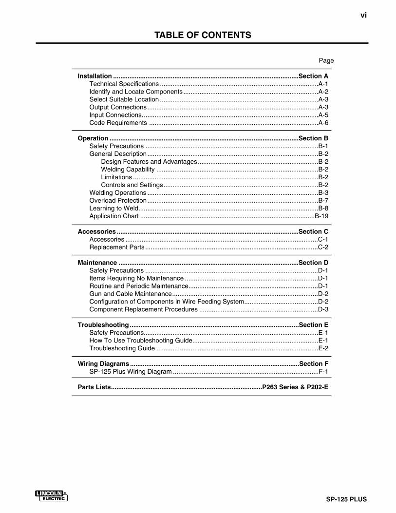
TABLE OF CONTENTS
Page
Installation .......................................................................................................Section ATechnical Specifications ........................................................................................A-1Identify and Locate Components ...........................................................................A-2Select Suitable Location ........................................................................................A-3Output Connections...............................................................................................A-3Input Connections..................................................................................................A-5Code Requirements ..............................................................................................A-6
Operation .........................................................................................................Section BSafety Precautions ................................................................................................B-1General Description ...............................................................................................B-2
Design Features and Advantages...................................................................B-2Welding Capability ..........................................................................................B-2Limitations .......................................................................................................B-2Controls and Settings......................................................................................B-2
Welding Operations ...............................................................................................B-3Overload Protection...............................................................................................B-7Learning to Weld....................................................................................................B-8Application Chart .................................................................................................B-19
Accessories .....................................................................................................Section CAccessories ...........................................................................................................C-1Replacement Parts ................................................................................................C-2
Maintenance ....................................................................................................Section DSafety Precautions ................................................................................................D-1Items Requiring No Maintenance ..........................................................................D-1Routine and Periodic Maintenance........................................................................D-1Gun and Cable Maintenance.................................................................................D-2Configuration of Components in Wire Feeding System.........................................D-2Component Replacement Procedures ..................................................................D-3
Troubleshooting ..............................................................................................Section ESafety Precautions.................................................................................................E-1How To Use Troubleshooting Guide......................................................................E-1Troubleshooting Guide ..........................................................................................E-2
Wiring Diagrams ..............................................................................................Section FSP-125 Plus Wiring Diagram .................................................................................F-1
Parts Lists....................................................................................P263 Series & P202-E

vii
SP-125 PLUS
A-1 INSTALLATION
SP-125 PLUS
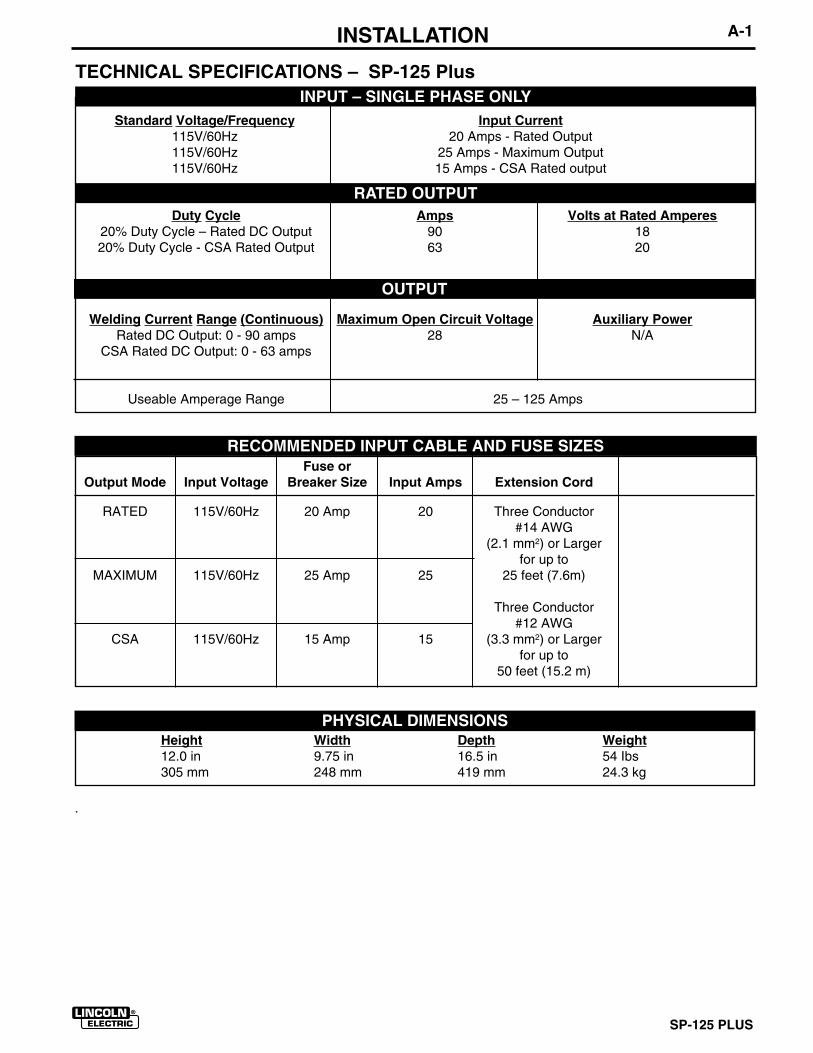
Fuse orOutput Mode Input Voltage Breaker Size Input Amps Extension Cord
RATED 115V/60Hz 20 Amp 20 Three Conductor#14 AWG
(2.1 mm2) or Largerfor up to
MAXIMUM 115V/60Hz 25 Amp 25 25 feet (7.6m)
Three Conductor#12 AWG
CSA 115V/60Hz 15 Amp 15 (3.3 mm2) or Largerfor up to
50 feet (15.2 m)
TECHNICAL SPECIFICATIONS – SP-125 PlusINPUT – SINGLE PHASE ONLY
RATED OUTPUT
OUTPUT
RECOMMENDED INPUT CABLE AND FUSE SIZES
Height Width Depth Weight12.0 in 9.75 in 16.5 in 54 Ibs305 mm 248 mm 419 mm 24.3 kg
PHYSICAL DIMENSIONS
Standard Voltage/Frequency Input Current115V/60Hz 20 Amps - Rated Output115V/60Hz 25 Amps - Maximum Output115V/60Hz 15 Amps - CSA Rated output
Duty Cycle Amps Volts at Rated Amperes20% Duty Cycle – Rated DC Output 90 1820% Duty Cycle - CSA Rated Output 63 20
Welding Current Range (Continuous) Maximum Open Circuit Voltage Auxiliary PowerRated DC Output: 0 - 90 amps 28 N/A
CSA Rated DC Output: 0 - 63 amps
Useable Amperage Range 25 – 125 Amps
.
A-2 INSTALLATION
SP-125 PLUS
Read entire installation section before startinginstallation.
SAFETY PRECAUTIONS
IDENTIFY AND LOCATE COMPONENTS
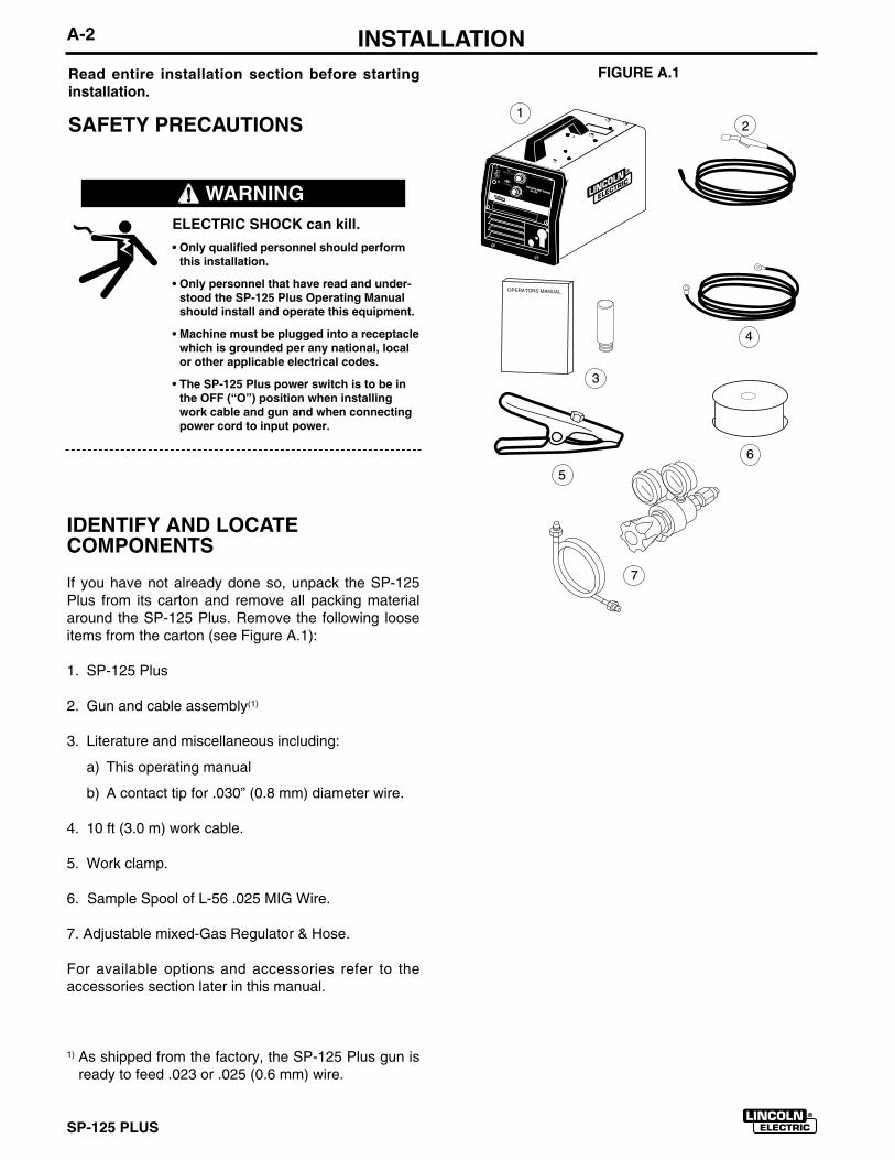
If you have not already done so, unpack the SP-125Plus from its carton and remove all packing materialaround the SP-125 Plus. Remove the following looseitems from the carton (see Figure A.1):
1. SP-125 Plus
2. Gun and cable assembly(1)
3. Literature and miscellaneous including:
a) This operating manual
b) A contact tip for .030” (0.8 mm) diameter wire.
4. 10 ft (3.0 m) work cable.
5. Work clamp.
6. Sample Spool of L-56 .025 MIG Wire.
7. Adjustable mixed-Gas Regulator & Hose.
For available options and accessories refer to theaccessories section later in this manual.
1) As shipped from the factory, the SP-125 Plus gun isready to feed .023 or .025 (0.6 mm) wire.
ELECTRIC SHOCK can kill.
• Only qualified personnel should performthis installation.
• Only personnel that have read and under-stood the SP-125 Plus Operating Manualshould install and operate this equipment.
• Machine must be plugged into a receptaclewhich is grounded per any national, localor other applicable electrical codes.
• The SP-125 Plus power switch is to be inthe OFF (“O”) position when installingwork cable and gun and when connectingpower cord to input power.
WARNING
FIGURE A.1
12
3
4
5
WELDING AMP RANGE
WELDING AMP RANGE
25-125 25-125
6
7
A-3 INSTALLATION
SP-125 PLUS
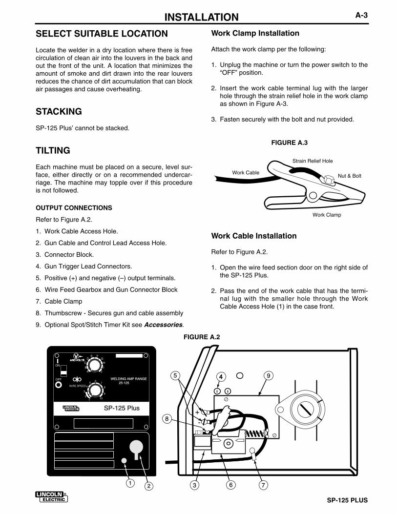
SELECT SUITABLE LOCATION
Locate the welder in a dry location where there is freecirculation of clean air into the louvers in the back andout the front of the unit. A location that minimizes theamount of smoke and dirt drawn into the rear louversreduces the chance of dirt accumulation that can blockair passages and cause overheating.
STACKING
SP-125 Plus’ cannot be stacked.
TILTING
Each machine must be placed on a secure, level sur-face, either directly or on a recommended undercar-riage. The machine may topple over if this procedureis not followed.
OUTPUT CONNECTIONS
Refer to Figure A.2.
1. Work Cable Access Hole.
2. Gun Cable and Control Lead Access Hole.
3. Connector Block.
4. Gun Trigger Lead Connectors.
5. Positive (+) and negative (–) output terminals.
6. Wire Feed Gearbox and Gun Connector Block
7. Cable Clamp
8. Thumbscrew - Secures gun and cable assembly
9. Optional Spot/Stitch Timer Kit see Accessories.
Work Clamp Installation
Attach the work clamp per the following:
1. Unplug the machine or turn the power switch to the“OFF” position.
2. Insert the work cable terminal lug with the largerhole through the strain relief hole in the work clampas shown in Figure A-3.
3. Fasten securely with the bolt and nut provided.
FIGURE A.3
445
8
3 761 2
SP-125 Plus
WELDING AMP RANGEWELDING AMP RANGE 25-125
+
-
9
Work Cable Installation
Refer to Figure A.2.
1. Open the wire feed section door on the right side ofthe SP-125 Plus.
2. Pass the end of the work cable that has the termi-nal lug with the smaller hole through the WorkCable Access Hole (1) in the case front.
Strain Relief Hole
Nut & Bolt
Work Clamp
Work Cable
FIGURE A.2
SP-125 PLUS
A-4 INSTALLATION3. Route the cable under and around the back of the
Wire Feed Gearbox (6).
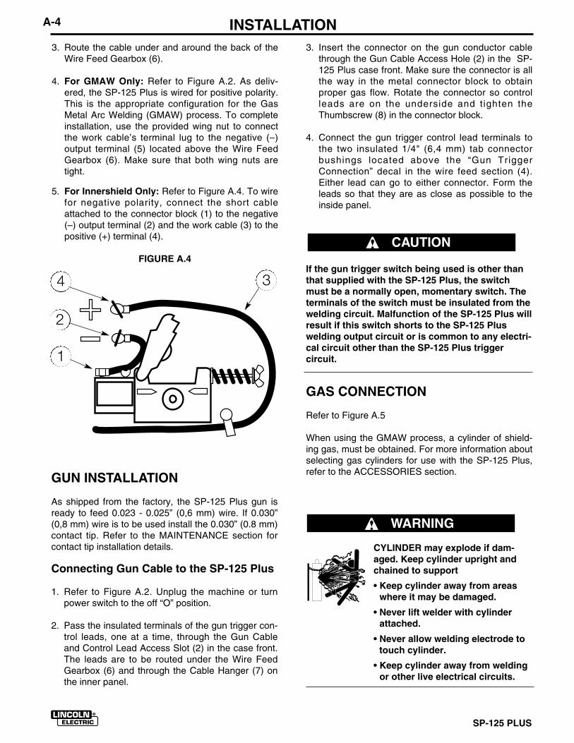
4. For GMAW Only: Refer to Figure A.2. As deliv-ered, the SP-125 Plus is wired for positive polarity.This is the appropriate configuration for the GasMetal Arc Welding (GMAW) process. To completeinstallation, use the provided wing nut to connectthe work cable’s terminal lug to the negative (–)output terminal (5) located above the Wire FeedGearbox (6). Make sure that both wing nuts aretight.
5. For Innershield Only: Refer to Figure A.4. To wirefor negative polarity, connect the short cableattached to the connector block (1) to the negative(–) output terminal (2) and the work cable (3) to thepositive (+) terminal (4).
FIGURE A.4
3. Insert the connector on the gun conductor cablethrough the Gun Cable Access Hole (2) in the SP-125 Plus case front. Make sure the connector is allthe way in the metal connector block to obtainproper gas flow. Rotate the connector so controlleads are on the underside and tighten theThumbscrew (8) in the connector block.
4. Connect the gun trigger control lead terminals tothe two insulated 1/4" (6,4 mm) tab connectorbushings located above the “Gun TriggerConnection” decal in the wire feed section (4).Either lead can go to either connector. Form theleads so that they are as close as possible to theinside panel.
If the gun trigger switch being used is other thanthat supplied with the SP-125 Plus, the switchmust be a normally open, momentary switch. Theterminals of the switch must be insulated from thewelding circuit. Malfunction of the SP-125 Plus willresult if this switch shorts to the SP-125 Pluswelding output circuit or is common to any electri-cal circuit other than the SP-125 Plus triggercircuit.
GAS CONNECTION
Refer to Figure A.5
When using the GMAW process, a cylinder of shield-ing gas, must be obtained. For more information aboutselecting gas cylinders for use with the SP-125 Plus,refer to the ACCESSORIES section.
CYLINDER may explode if dam-aged. Keep cylinder upright andchained to support
• Keep cylinder away from areaswhere it may be damaged.
• Never lift welder with cylinderattached.
• Never allow welding electrode totouch cylinder.
• Keep cylinder away from weldingor other live electrical circuits.
GUN INSTALLATION
As shipped from the factory, the SP-125 Plus gun isready to feed 0.023 - 0.025” (0,6 mm) wire. If 0.030”(0,8 mm) wire is to be used install the 0.030” (0.8 mm)contact tip. Refer to the MAINTENANCE section forcontact tip installation details.
Connecting Gun Cable to the SP-125 Plus
1. Refer to Figure A.2. Unplug the machine or turnpower switch to the off “O” position.
2. Pass the insulated terminals of the gun trigger con-trol leads, one at a time, through the Gun Cableand Control Lead Access Slot (2) in the case front.The leads are to be routed under the Wire FeedGearbox (6) and through the Cable Hanger (7) onthe inner panel.
CAUTION
WARNING
1
2
34
A-5 INSTALLATION
SP-125 PLUS
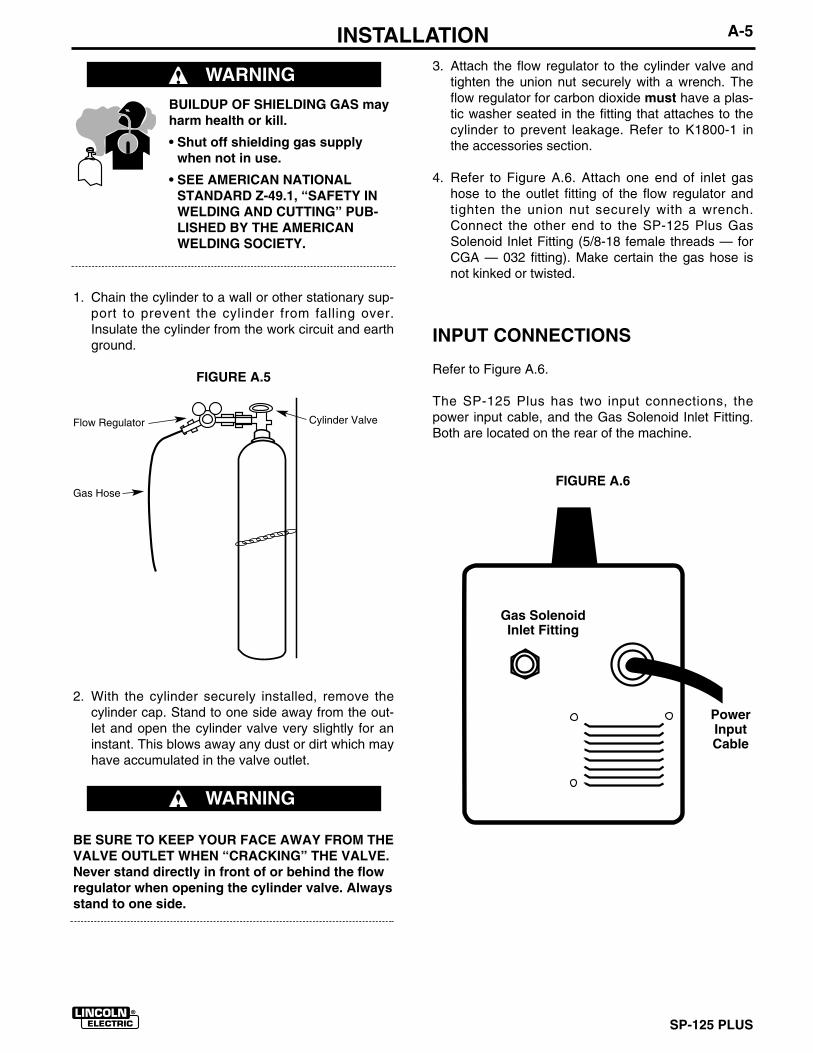
3. Attach the flow regulator to the cylinder valve andtighten the union nut securely with a wrench. Theflow regulator for carbon dioxide must have a plas-tic washer seated in the fitting that attaches to thecylinder to prevent leakage. Refer to K1800-1 inthe accessories section.
4. Refer to Figure A.6. Attach one end of inlet gashose to the outlet fitting of the flow regulator andtighten the union nut securely with a wrench.Connect the other end to the SP-125 Plus GasSolenoid Inlet Fitting (5/8-18 female threads — forCGA — 032 fitting). Make certain the gas hose isnot kinked or twisted.
INPUT CONNECTIONS
Refer to Figure A.6.
The SP-125 Plus has two input connections, thepower input cable, and the Gas Solenoid Inlet Fitting.Both are located on the rear of the machine.
FIGURE A.6
BUILDUP OF SHIELDING GAS mayharm health or kill.
• Shut off shielding gas supplywhen not in use.
• SEE AMERICAN NATIONALSTANDARD Z-49.1, “SAFETY INWELDING AND CUTTING” PUB-LISHED BY THE AMERICANWELDING SOCIETY.
1. Chain the cylinder to a wall or other stationary sup-port to prevent the cylinder from falling over.Insulate the cylinder from the work circuit and earthground.
FIGURE A.5
2. With the cylinder securely installed, remove thecylinder cap. Stand to one side away from the out-let and open the cylinder valve very slightly for aninstant. This blows away any dust or dirt which mayhave accumulated in the valve outlet.
BE SURE TO KEEP YOUR FACE AWAY FROM THEVALVE OUTLET WHEN “CRACKING” THE VALVE.Never stand directly in front of or behind the flowregulator when opening the cylinder valve. Alwaysstand to one side.
WARNING
WARNING
Cylinder Valve
Gas Hose
Flow Regulator
Gas SolenoidInlet Fitting
PowerInputCable

A-6 INSTALLATION
SP-125 PLUS
CODE REQUIREMENTS FOR INPUTCONNECTIONS
This welding machine must be connected topower source in accordance with applicable elec-trical codes.
The United States National Electrical Code (Article630-B, 1990 Edition) provides standards for amperagehandling capability of supply conductors based onduty cycle of the welding source.
If there is any question about the installation meetingapplicable electrical code requirements, consult aqualified electrician.
Requirements For Rated Output
A power cord with a 15 amp, 125 volt, three prongplug (NEMA Type 5-15P) is factory installed on theSP-125 Plus. Connect this plug to a mating groundedreceptacle which is connected to a 20 amp branch cir-cuit with a nominal voltage rating of 115 to 125 volts,60 Hertz, AC only.
The rated output with this installation is 90 amps, 18Volts, 20% duty cycle (2 minutes of every 10 minutesused for welding).
Do not connect the SP-125 Plus to an input powersupply with a rated voltage that is greater than 125volts.
Do not remove the power cord ground prong.
Requirements For Maximum Output
In order to utilize the maximum output capability of themachine, a branch circuit capable of 25 amps at 115to 125 volts, 60 Hertz is required. This generallyapplies when welding steel that is equal to or greaterthan 12 gauge, 0.105” (2.5 mm) in thickness.
Requirements For CSA Rated Output
A line cord with a 15 amp, 125 volt, three-prong plug(NEMA Type 5-15P) is factory installed. Connect thisplug to a mating grounded receptacle which is con-nected to a 15 amp branch circuit with a nominal volt-age rating of 115 volts to 125 volts, 60 hertz, AC only.
With this installation, the SP-125 Plus can be used atan output of 63 amps, 20 volts, 20% duty cycle.
WARNING
CAUTION
SP-125 PLUS
B-1 OPERATION
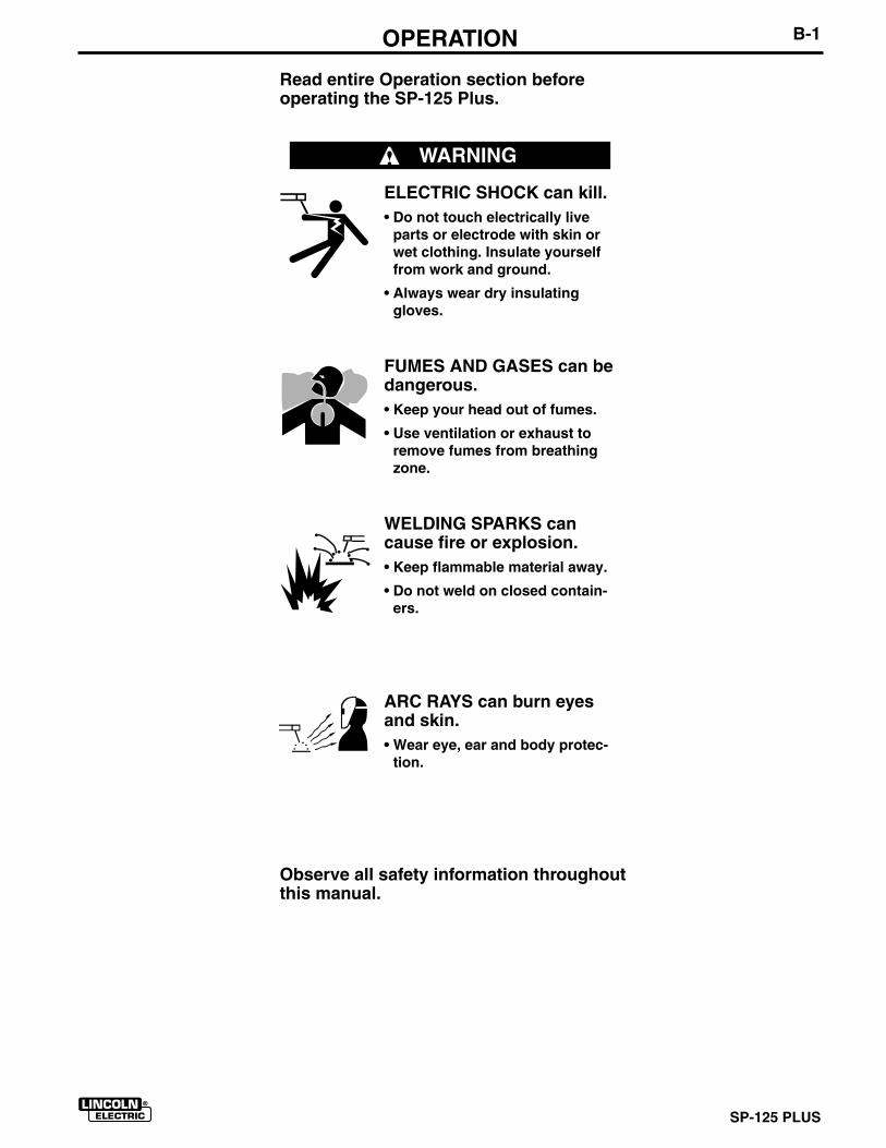
Read entire Operation section beforeoperating the SP-125 Plus.
ELECTRIC SHOCK can kill.• Do not touch electrically live
parts or electrode with skin orwet clothing. Insulate yourselffrom work and ground.
• Always wear dry insulatinggloves.
FUMES AND GASES can bedangerous.• Keep your head out of fumes.
• Use ventilation or exhaust toremove fumes from breathingzone.
WELDING SPARKS cancause fire or explosion.• Keep flammable material away.
• Do not weld on closed contain-ers.
ARC RAYS can burn eyesand skin.• Wear eye, ear and body protec-
tion.
Observe all safety information throughoutthis manual.
WARNING
SP-125 PLUSSP-125 PLUS
B-2 OPERATIONGENERAL DESCRIPTION
The SP-125 Plus is a complete semiautomatic con-stant voltage DC arc welding machine. Included is asolid state controlled, single phase constant voltagetransformer/ rectifier power source and a wire feederfor feeding solid steel electrode and cored electrode.
The SP-125 Plus is ideally suited for individuals hav-ing access to 115 volt AC input power, and wantingthe ease of use, quality and dependability of both gasmetal arc welding or GMAW (also known as MIGwelding) and the Innershield electrode process (selfshielded flux cored or FCAW). The SP-125 Plus is arugged and reliable machine that has been designedfor dependable service and long life.
RECOMMENDED PROCESSES
The SP-125 Plus can be used for welding mild steelusing the GMAW, single pass, process which requiresa supply of shielding gas or it can be used for the selfshielded, Innershield electrode process (FCAW). TheSP-125 Plus is configured for use with the GMAW(MIG) process as delivered from the factory.
OPERATIONAL FEATURES AND CONTROLS
The SP-125 Plus has the following controls as stan-dard: Power ON/OFF Switch, Voltage Control, WireSpeed Control, and a Circuit Breaker.
DESIGN FEATURES AND ADVANTAGES
● Operates on 115 volt input — no special wiringrequired.
● Solid state output control.
● “Cold electrode” until gun trigger is pressed for anadded measure of safety.
● Overload protection — incorporates both a thermo-stat and a circuit breaker.
● Quality wire drive with electronic overload protec-tion.
● Easy-to-set continuous range controls for precisesetting of arc voltage and wire speed.
● Continuous voltage control.
● “Quick Release” idle roll pressure arm is easilyadjusted.
● Reversible, dual groove drive roll. Drive roll willfeed .023-.035” (0.6- 0.9 mm) diameter wire.
● Accommodates both 8” (200 mm) diameter and 4”(100 mm) diameter spools of wire.
● No external shielding gas is required when usedwith Lincoln Innershield .035” (0,9 mm) NR®-211-MP electrode.
● Easy to change polarity.
● Accepts optional Spot/Stitch Timer Kit.
WELDING CAPABILITY
The SP-125 Plus, as shipped, is rated at 90 amps, 18volts, at 20% duty cycle on a ten minute basis. It iscapable of higher duty cycles at lower output currents.
LIMITATIONS
Arc Gouging cannot be performed with the SP-125Plus. The SP-125 Plus is not recommended for pipethawing.
CONTROLS AND SETTINGS
Refer to Figures B.1a & B.1b.
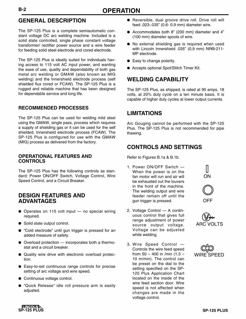
1. Power ON/OFF Switch —When the power is on thefan motor will run and air willbe exhausted out the louversin the front of the machine.The welding output and wirefeeder remain off until thegun trigger is pressed.
2. Voltage Control — A contin-uous control that gives fullrange adjustment of powersource output voltage.Voltage can be adjustedwhile welding.
3. Wire Speed Control —Controls the wire feed speedfrom 50 – 400 in /min (1.3 –10 m/min). The control canbe preset on the dial to thesetting specified on the SP-125 Plus Application Chartlocated on the inside of thewire feed section door. Wirespeed is not affected whenchanges are made in thevoltage control.
OFF
ON
ARC VOLTS
WIRE SPEED
ON
ARC VOLTS
SP-125 PLUS
B-3 OPERATION
FIGURE B.1a
Refer to Figure B.1b
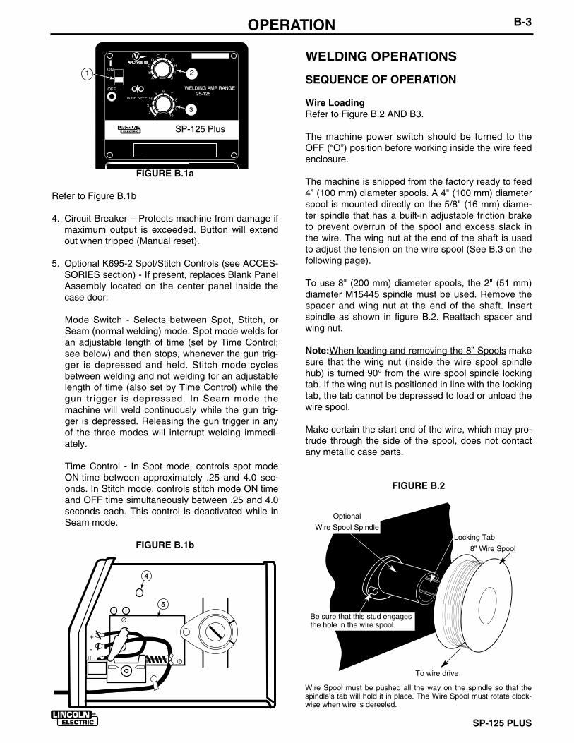
4. Circuit Breaker – Protects machine from damage ifmaximum output is exceeded. Button will extendout when tripped (Manual reset).
5. Optional K695-2 Spot/Stitch Controls (see ACCES-SORIES section) - If present, replaces Blank PanelAssembly located on the center panel inside thecase door:
Mode Switch - Selects between Spot, Stitch, orSeam (normal welding) mode. Spot mode welds foran adjustable length of time (set by Time Control;see below) and then stops, whenever the gun trig-ger is depressed and held. Stitch mode cyclesbetween welding and not welding for an adjustablelength of time (also set by Time Control) while thegun trigger is depressed. In Seam mode themachine will weld continuously while the gun trig-ger is depressed. Releasing the gun trigger in anyof the three modes will interrupt welding immedi-ately.
Time Control - In Spot mode, controls spot modeON time between approximately .25 and 4.0 sec-onds. In Stitch mode, controls stitch mode ON timeand OFF time simultaneously between .25 and 4.0seconds each. This control is deactivated while inSeam mode.
FIGURE B.1b
WELDING OPERATIONS
SEQUENCE OF OPERATION
Wire LoadingRefer to Figure B.2 AND B3.
The machine power switch should be turned to theOFF (“O”) position before working inside the wire feedenclosure.
The machine is shipped from the factory ready to feed4” (100 mm) diameter spools. A 4" (100 mm) diameterspool is mounted directly on the 5/8" (16 mm) diame-ter spindle that has a built-in adjustable friction brake to prevent overrun of the spool and excess slack inthe wire. The wing nut at the end of the shaft is usedto adjust the tension on the wire spool (See B.3 on thefollowing page).
To use 8" (200 mm) diameter spools, the 2" (51 mm)diameter M15445 spindle must be used. Remove thespacer and wing nut at the end of the shaft. Insertspindle as shown in figure B.2. Reattach spacer andwing nut.
Note:When loading and removing the 8” Spools makesure that the wing nut (inside the wire spool spindlehub) is turned 90° from the wire spool spindle lockingtab. If the wing nut is positioned in line with the lockingtab, the tab cannot be depressed to load or unload thewire spool.
Make certain the start end of the wire, which may pro-trude through the side of the spool, does not contactany metallic case parts.
FIGURE B.2
11
SP-125 Plus
WELDING AMP RANGE 25-125
3
2
4
5
+
-
Wire Spool must be pushed all the way on the spindle so that thespindle’s tab will hold it in place. The Wire Spool must rotate clock-wise when wire is dereeled.
To wire drive
Be sure that this stud engagesthe hole in the wire spool.
8” Wire Spool
Optional
Wire Spool SpindleLocking Tab
SP-125 PLUS
B-4 OPERATIONFIGURE B.3
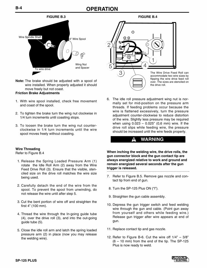
Note: The brake should be adjusted with a spool ofwire installed. When properly adjusted it shouldmove freely but not coast.
Friction Brake Adjustments
1. With wire spool installed, check free movementand coast of the spool.
2. To tighten the brake turn the wing nut clockwise in1/4 turn increments until coasting stops.
3. To loosen the brake turn the wing nut counter-clockwise in 1/4 turn increments until the wirespool moves freely without coasting.
Wire Threading Refer to Figure B.4
1. Release the Spring Loaded Pressure Arm (1)rotate the Idle Roll Arm (2) away from the WireFeed Drive Roll (3). Ensure that the visible, sten-ciled size on the drive roll matches the wire sizebeing used.
2. Carefully detach the end of the wire from thespool. To prevent the spool from unwinding, donot release the wire until after step 5.
3. Cut the bent portion of wire off and straighten thefirst 4” (100 mm).
4. Thread the wire through the In-going guide tube(4), over the drive roll (3), and into the out-goingguide tube (5).
5. Close the idle roll arm and latch the spring loadedpressure arm (2) in place (now you may releasethe welding wire).
6. The idle roll pressure adjustment wing nut is nor-mally set for mid-position on the pressure armthreads. If feeding problems occur because thewire is flattened excessively, turn the pressureadjustment counter-clockwise to reduce distortionof the wire. Slightly less pressure may be requiredwhen using 0.023 – 0.025” (0,6 mm) wire. If thedrive roll slips while feeding wire, the pressureshould be increased until the wire feeds properly.
When inching the welding wire, the drive rolls, thegun connector block and the gun contact tip arealways energized relative to work and ground andremain energized several seconds after the guntrigger is released.
7. Refer to Figure B.5. Remove gas nozzle and con-tact tip from end of gun.
8. Turn the SP-125 Plus ON (“I”).
9. Straighten the gun cable assembly.
10. Depress the gun trigger switch and feed weldingwire through the gun and cable. (Point gun awayfrom yourself and others while feeding wire.)Release gun trigger after wire appears at end ofgun.
11. Replace contact tip and gas nozzle.
12. Refer to Figure B-6. Cut the wire off 1/4” – 3/8”(6 – 10 mm) from the end of the tip. The SP-125Plus is now ready to weld.
FIGURE B.4
The Wire Drive Feed Roll canaccommodate two wire sizes byflipping the wire drive feed rollover. The sizes are stenciled onthe drive roll.
1
2
345
WARNING
Wire Spindle Shaft4" Wire Spool
Wing Nutand SpacerTo wire drive
SP-125 PLUS
B-5 OPERATION
Shielding GasWhen using the GMAW process, a cylinder of shield-ing gas, must be obtained. Refer to the ACCES-SORIES section for more information about selectinggas cylinders for use with the SP-125 Plus.
1. For CO2, open the cylinder very slowly. For argon-mixed gas, open cylinder valve slowly a fraction ofa turn. When the cylinder pressure gauge pointerstops moving, open the valve fully.
2. If using a regulator with an adjustable flow meter,close the gun trigger and adjust the flow to give 15– 20 cubic ft per hour (CFH) (7 – 10 I/min) [use 20-– 25 CFH (10 – 12 I/min) when welding out ofposition or in a drafty location for CO2]. For argonmixed gas, trigger to release gas pressure, andturn off the adjust the flow to give 25 – 30 CFH(12 – 14 I/min).
3. Keep the cylinder valve closed, except when usingthe SP-125 Plus. When finished welding:
a) Close the cylinder valve to stop gas flow.
b) Depress the gun trigger briefly to release thepressure in the gas hose.
c) Turn off the SP-125 Plus.
Making A Weld1. See Recommended Processes And Equipment
section for selection of welding wire and shieldinggas and for range of metal thicknesses that can bewelded.
2. See the Application Chart on the inside of wirefeed section door for information on setting theSP-125 Plus controls.
3. Set the Voltage (“V”) and Wire Speed (“olo’”) con-trols to the settings suggested for the welding wireand base metal thickness being used.
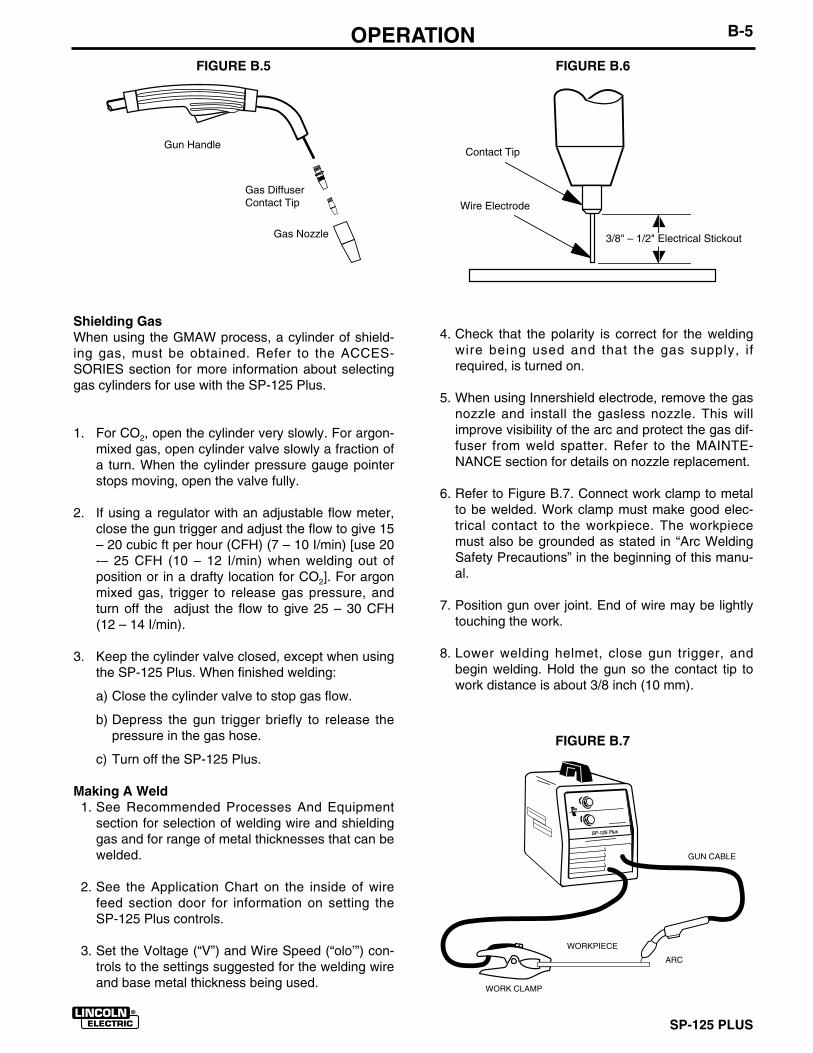
FIGURE B.6FIGURE B.5
Gun Handle
Gas DiffuserContact Tip
Gas Nozzle
4. Check that the polarity is correct for the weldingwire being used and that the gas supply, ifrequired, is turned on.
5. When using Innershield electrode, remove the gasnozzle and install the gasless nozzle. This willimprove visibility of the arc and protect the gas dif-fuser from weld spatter. Refer to the MAINTE-NANCE section for details on nozzle replacement.
6. Refer to Figure B.7. Connect work clamp to metalto be welded. Work clamp must make good elec-trical contact to the workpiece. The workpiecemust also be grounded as stated in “Arc WeldingSafety Precautions” in the beginning of this manu-al.
7. Position gun over joint. End of wire may be lightlytouching the work.
8. Lower welding helmet, close gun trigger, andbegin welding. Hold the gun so the contact tip towork distance is about 3/8 inch (10 mm).
3/8" – 1/2" Electrical Stickout
Contact Tip
Wire Electrode
FIGURE B.7
WORKPIECE
GUN CABLE
ARC
WORK CLAMP
SP-125 PlusSP-125 Plus
SP-125 PLUS
B-6 OPERATION9. To stop welding, release the gun trigger and then
pull the gun away from the work after the arc goesout.
10. When no more welding is to be done, close valveon gas cylinder (if used), momentarily operate guntrigger to release gas pressure, and turn off theSP-125 Plus.
Cleaning Tip And NozzleClean the contact tip and nozzle to avoid arc bridgingbetween the nozzle and contact tip which can result ina shorted nozzle, poor welds and an overheated gun.Hint: Anti-stick spray or gel, available from a weldingsupply distributor, may reduce buildup and aid in spat-ter removal.
PROCESS GUIDELINES
The SP-125 Plus can be used for welding mild steelusing the GMAW, single pass, process which requiresa supply of shielding gas or it can be used for the selfshielded, Innershield electrode process.
The recommended gas and electrode for GMAW iswelding grade mixed CO2 and Argon (75-80%) gasand 0.025” (0 6 mm) diameter Lincoln L-56 mild-steelwelding wire [supplied on 121/2 Ib (6 kg) spools]. For14 gauge (2,0 mm) and thinner CO2, or blended gas isacceptable. A mixed gas consisting of 75 to 80%Argon and 20 to 25% CO2 is recommended for weld-ing on heavier gauge [12 gauge (2,5 mm) for example]steel.
The recommended electrode for the self-shieldedprocess is 0.035” (0,9 mm) diameter LincolnInnershield NR-211-MP on 10 Ib (4,5 kg) spools. Thiselectrode can be used for all position welding of 20gauge through 5/16” (1,0 – 8,0 mm) thick steel [multi-ple passes are required for 1/4” and 5/16” (6,0 and 8,0mm)].
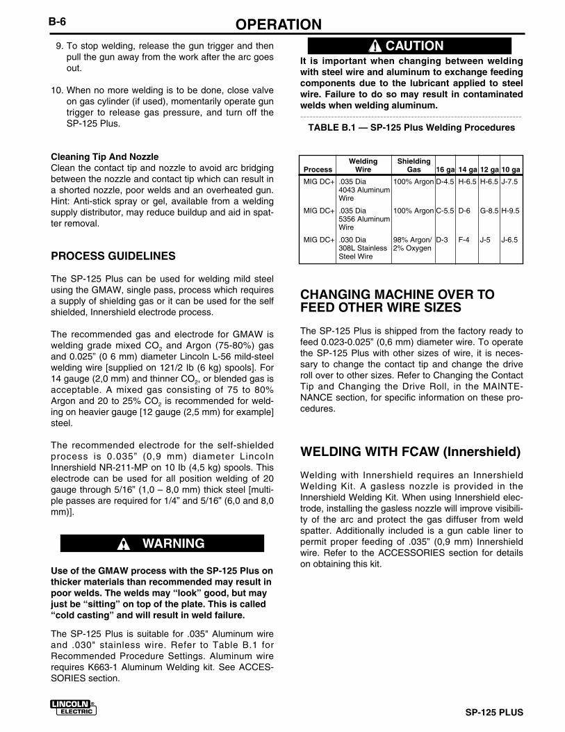
The SP-125 Plus is suitable for .035" Aluminum wireand .030" stainless wire. Refer to Table B.1 forRecommended Procedure Settings. Aluminum wirerequires K663-1 Aluminum Welding kit. See ACCES-SORIES section.
It is important when changing between weldingwith steel wire and aluminum to exchange feedingcomponents due to the lubricant applied to steelwire. Failure to do so may result in contaminatedwelds when welding aluminum.------------------------------------------------------------------------
TABLE B.1 — SP-125 Plus Welding Procedures
CHANGING MACHINE OVER TOFEED OTHER WIRE SIZES
The SP-125 Plus is shipped from the factory ready tofeed 0.023-0.025” (0,6 mm) diameter wire. To operatethe SP-125 Plus with other sizes of wire, it is neces-sary to change the contact tip and change the driveroll over to other sizes. Refer to Changing the ContactTip and Changing the Drive Roll, in the MAINTE-NANCE section, for specific information on these pro-cedures.
WELDING WITH FCAW (Innershield)
Welding with Innershield requires an InnershieldWelding Kit. A gasless nozzle is provided in theInnershield Welding Kit. When using Innershield elec-trode, installing the gasless nozzle will improve visibili-ty of the arc and protect the gas diffuser from weldspatter. Additionally included is a gun cable liner topermit proper feeding of .035” (0,9 mm) Innershieldwire. Refer to the ACCESSORIES section for detailson obtaining this kit.
Welding ShieldingProcess Wire Gas 16 ga 14 ga 12 ga 10 ga
MIG DC+ .035 Dia 100% Argon D-4.5 H-6.5 H-6.5 J-7.54043 AluminumWire
MIG DC+ .035 Dia 100% Argon C-5.5 D-6 G-8.5 H-9.55356 AluminumWire
MIG DC+ .030 Dia 98% Argon/ D-3 F-4 J-5 J-6.5308L Stainless 2% OxygenSteel Wire
WARNING
Use of the GMAW process with the SP-125 Plus onthicker materials than recommended may result inpoor welds. The welds may “look” good, but mayjust be “sitting” on top of the plate. This is called“cold casting” and will result in weld failure.
CAUTION

SP-125 PLUS
B-7 OPERATIONOVERLOAD PROTECTION
Output OverloadThe SP-125 Plus is equipped with a circuit breakerwhich protects the machine from potential damagefrom excessive output current. The circuit breaker but-ton will extend out when tripped. The circuit breakermust be manually reset.
Thermal ProtectionThe SP-125 Plus duty cycle is exceeded a thermostatwill shut off the output until the machine cools to a nor-mal operating temperature. This is an automatic func-tion and is self resetting.
Wire Feed Overload ProtectionIf the SP-125 Plus has an automatic electronic protec-tion circuit to protect the wire feed motor. If excessivemotor overload occurs (due to excessive feedingforce, jammed drive rolls, or shorted motor leads) thecircuit will shut down the wire feed motor and thewelding power output.
The wire feed shut-down circuit will reset automaticallywhen the gun trigger is released. However shut-downwill reoccur if the overload situation is not corrected.
SP-125 PLUS
B-8 LEARNING TO WELDLEARNING TO WELD
No one can learn to weld simply by reading about it.Skill comes only with practice. The following pages willhelp the inexperienced operator to understand weld-ing and develop this skill. For more detailed informa-tion, order a copy of “New Lessons in Arc Welding”listed at the end of this manual.
THE ARC-WELDING CIRCUIT
The operator’s knowledge of arc welding must gobeyond the arc itself. The operator must know how tocontrol the arc, and this requires a knowledge of thewelding circuit and the equipment that provides theelectric current used in the arc. Figure B.7 illustratesthe welding circuit for a typical welding machine. Thecircuit begins where the gun cable is attached to thewelding machine. Current flows through the gun cable,gun, and contact tip, to the wire and across the arc.On the work side of the arc, current flows through thebase metal to the work cable and back to the weldingmachine. This circuit must be complete for the currentto flow.
This machine’s welding circuit has a voltage output of33 volts DC maximum. This voltage is quite low and isonly present when the gun trigger is depressed.
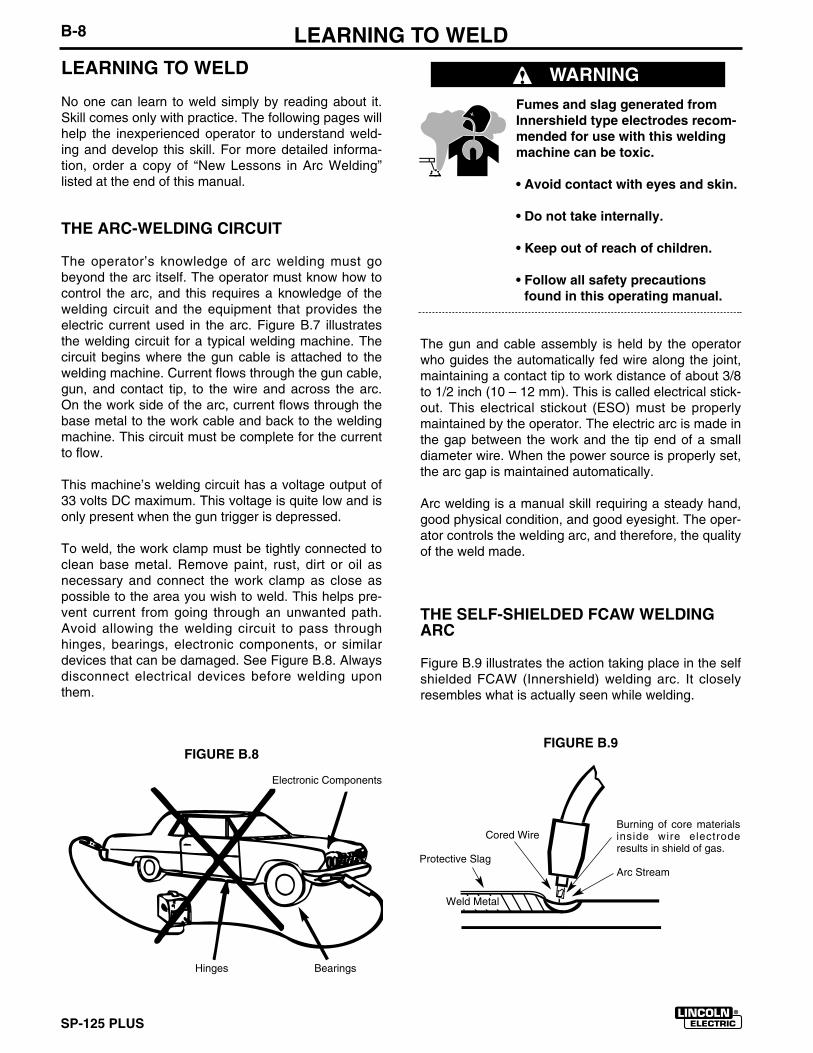
To weld, the work clamp must be tightly connected toclean base metal. Remove paint, rust, dirt or oil asnecessary and connect the work clamp as close aspossible to the area you wish to weld. This helps pre-vent current from going through an unwanted path.Avoid allowing the welding circuit to pass throughhinges, bearings, electronic components, or similardevices that can be damaged. See Figure B.8. Alwaysdisconnect electrical devices before welding uponthem.
Fumes and slag generated fromInnershield type electrodes recom-mended for use with this weldingmachine can be toxic.
• Avoid contact with eyes and skin.
• Do not take internally.
• Keep out of reach of children.
• Follow all safety precautionsfound in this operating manual.
The gun and cable assembly is held by the operatorwho guides the automatically fed wire along the joint,maintaining a contact tip to work distance of about 3/8to 1/2 inch (10 – 12 mm). This is called electrical stick-out. This electrical stickout (ESO) must be properlymaintained by the operator. The electric arc is made inthe gap between the work and the tip end of a smalldiameter wire. When the power source is properly set,the arc gap is maintained automatically.
Arc welding is a manual skill requiring a steady hand,good physical condition, and good eyesight. The oper-ator controls the welding arc, and therefore, the qualityof the weld made.
THE SELF-SHIELDED FCAW WELDINGARC
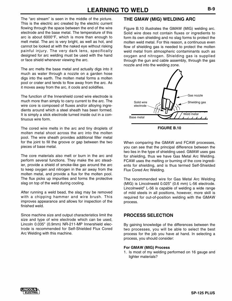
Figure B.9 illustrates the action taking place in the selfshielded FCAW (Innershield) welding arc. It closelyresembles what is actually seen while welding.
FIGURE B.9
WARNING
FIGURE B.8
Electronic Components
Hinges Bearings
Burning of core materialsinside wire electroderesults in shield of gas.
Arc Stream
Cored Wire
Protective Slag
Weld Metal
SP-125 PLUS
B-9 LEARNING TO WELDThe “arc stream” is seen in the middle of the picture.This is the electric arc created by the electric currentflowing through the space between the end of the wireelectrode and the base metal. The temperature of thisarc is about 6000°F, which is more than enough tomelt metal. The arc is very bright, as well as hot, andcannot be looked at with the naked eye without riskingpainful injury. The very dark lens, specif icallydesigned for arc welding must be used with the handor face shield whenever viewing the arc.
The arc melts the base metal and actually digs into itmuch as water through a nozzle on a garden hosedigs into the earth. The molten metal forms a moltenpool or crater and tends to flow away from the arc. Asit moves away from the arc, it cools and solidifies.
The function of the Innershield cored wire electrode ismuch more than simply to carry current to the arc. Thewire core is composed of fluxes and/or alloying ingre-dients around which a steel sheath has been formed.It is simply a stick electrode turned inside out in a con-tinuous wire form.
The cored wire melts in the arc and tiny droplets ofmolten metal shoot across the arc into the moltenpool. The wire sheath provides additional filler metalfor the joint to fill the groove or gap between the twopieces of base metal.
The core materials also melt or burn in the arc andperform several functions. They make the arc stead-ier, provide a shield of smoke-like gas around the arcto keep oxygen and nitrogen in the air away from themolten metal, and provide a flux for the molten pool.The flux picks up impurities and forms the protectiveslag on top of the weld during cooling.
After running a weld bead, the slag may be removedwith a chipping hammer and wire brush. Thisimproves appearance and allows for inspection of thefinished weld.
Since machine size and output characteristics limit thesize and type of wire electrode which can be used,Lincoln 0.035" (0.9mm) NR-211-MP Innershield elec-trode is recommended for Self-Shielded Flux CoredArc Welding with this machine.
THE GMAW (MIG) WELDING ARC
Figure B.10 illustrates the GMAW (MIG) welding arc.Solid wire does not contain fluxes or ingredients toform its own shielding and no slag forms to protect themolten weld metal. For this reason, a continuous evenflow of shielding gas is needed to protect the moltenweld metal from atmospheric contaminants such asoxygen and nitrogen. Shielding gas is suppliedthrough the gun and cable assembly, through the gasnozzle and into the welding zone.
When comparing the GMAW and FCAW processes,you can see that the principal difference between thetwo lies in the type of shielding used. GMAW uses gasfor shielding, thus we have Gas Metal Arc Welding.FCAW uses the melting or burning of the core ingredi-ents for shielding, and is thus termed Self-ShieldedFlux Cored Arc Welding.
The recommended wire for Gas Metal Arc Welding(MIG) is Lincolnweld 0.025” (0.6 mm) L-56 electrode.Lincolnweld” L-56 is capable of welding a wide rangeof mild steels in all positions, however, more skill isrequired for out-of-position welding with the GMAWprocess.
PROCESS SELECTION
By gaining knowledge of the differences between thetwo processes, you will be able to select the bestprocess for the job you have at hand. In selecting aprocess, you should consider:
For GMAW (MIG) Process1. Is most of my welding performed on 16 gauge and
lighter materials?
FIGURE B.10
Gas nozzle
Shielding gasSolid wireelectrode
Base metalWeld metal
SP-125 PLUS
B-10 LEARNING TO WELD2. Can I afford the extra expense, space, and lack of
portability required for gas cylinders and gas sup-ply?
3. Do I require clean, finished-looking welds?
If you have answered yes to all the above questionsGMAW may be the process for you. If you haveanswered no to any of the above questions, then youshould consider using the FCAW process.
For FCAW (Innershield) Process1. Do I want simplicity and portability?
2. Will welding be performed outdoors or under windyconditions?
3. Do I require good all position welding capability?
4. Will most welding be performed on 16 gauge andheavier, somewhat rusty or dirty materials?
5. Weld must be cleaned prior to painting.
COMMON METALS
Most metals found around the farm, small shop orhome are low carbon steel, sometimes referred to asmild steel. Typical items made with this type of steelinclude most sheet metal, plate, pipe and rolledshapes such as channels and angle irons. This type ofsteel can usually be easily welded without special pre-cautions. Some steels, however, contain higher car-bon levels or other alloys and are more difficult toweld. Basically, if a magnet sticks to the metal andyou can easily cut the metal with a file, chances aregood that the metal is mild steel and that you will beable to weld the material. In addition, aluminum andstainless steel can be welded using the K664-1Aluminum Welding Kit. For further information onidentifying various types of steels and other metals,and for proper procedures for welding them, we againsuggest you purchase a copy of “New Lessons in ArcWelding”.
Regardless of the type of metal being welded, in orderto get a quality weld, it is important that the metal isfree of oil, paint, rust or other contaminants.
JOINT TYPES AND POSITIONS
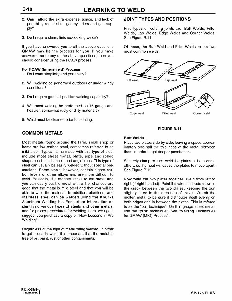
Five types of welding joints are: Butt Welds, FilletWelds, Lap Welds, Edge Welds and Corner Welds.See Figure B.11.
Of these, the Butt Weld and Fillet Weld are the twomost common welds.
FIGURE B.11
Butt WeldsPlace two plates side by side, leaving a space approx-imately one half the thickness of the metal betweenthem in order to get deeper penetration.
Securely clamp or tack weld the plates at both ends,otherwise the heat will cause the plates to move apart.See Figure B.12.
Now weld the two plates together. Weld from left toright (if right handed). Point the wire electrode down inthe crack between the two plates, keeping the gunslightly tilted in the direction of travel. Watch themolten metal to be sure it distributes itself evenly onboth edges and in between the plates. This is referedto as the “pull technique”. On thin gauge sheet metal,use the “push technique”. See “Welding Techniquesfor GMAW (MIG) Process”.
Butt weld Lap weld
Edge weld Fillet weld Corner weld
SP-125 PLUS
B-11 LEARNING TO WELD
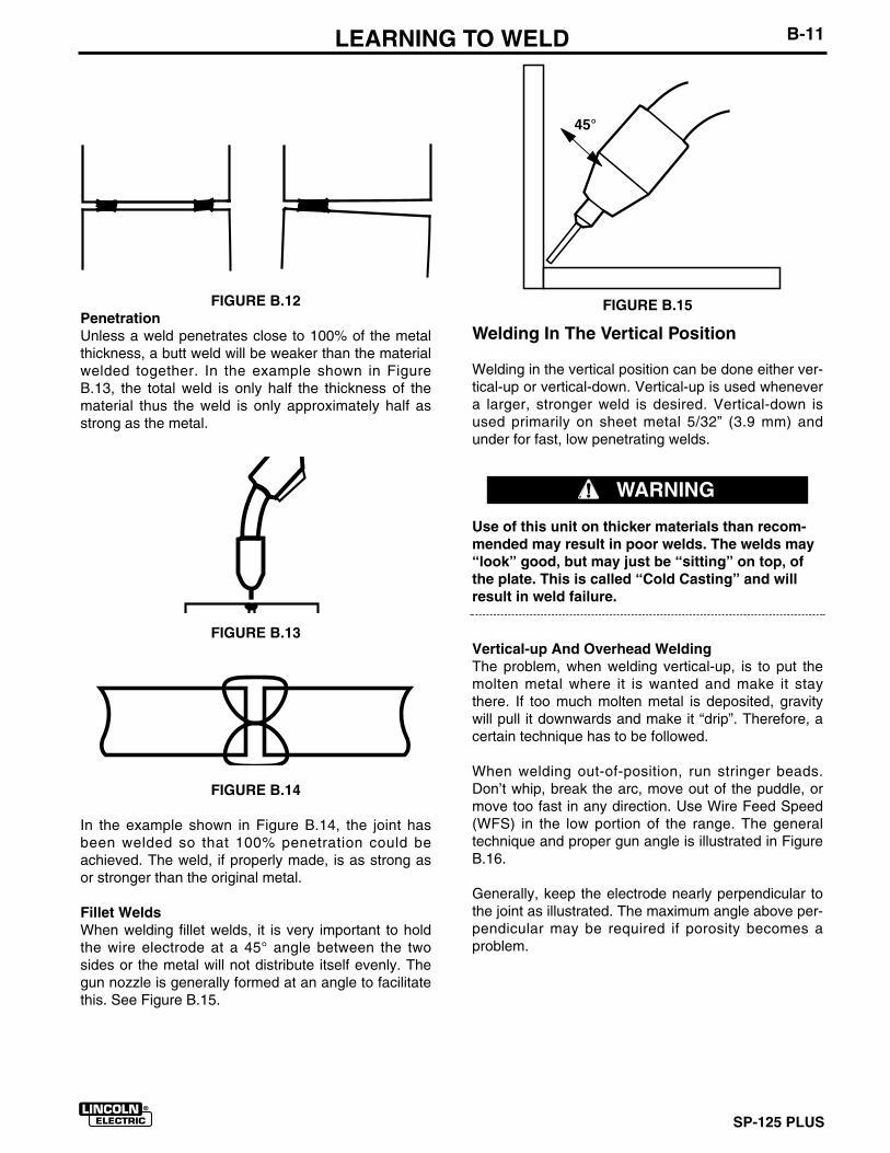
FIGURE B.12PenetrationUnless a weld penetrates close to 100% of the metalthickness, a butt weld will be weaker than the materialwelded together. In the example shown in FigureB.13, the total weld is only half the thickness of thematerial thus the weld is only approximately half asstrong as the metal.
FIGURE B.13
FIGURE B.14
In the example shown in Figure B.14, the joint hasbeen welded so that 100% penetration could beachieved. The weld, if properly made, is as strong asor stronger than the original metal.
Fillet WeldsWhen welding fillet welds, it is very important to holdthe wire electrode at a 45° angle between the twosides or the metal will not distribute itself evenly. Thegun nozzle is generally formed at an angle to facilitatethis. See Figure B.15.
FIGURE B.15
Welding In The Vertical Position
Welding in the vertical position can be done either ver-tical-up or vertical-down. Vertical-up is used whenevera larger, stronger weld is desired. Vertical-down isused primarily on sheet metal 5/32” (3.9 mm) andunder for fast, low penetrating welds.
Use of this unit on thicker materials than recom-mended may result in poor welds. The welds may“look” good, but may just be “sitting” on top, ofthe plate. This is called “Cold Casting” and willresult in weld failure.
Vertical-up And Overhead WeldingThe problem, when welding vertical-up, is to put themolten metal where it is wanted and make it staythere. If too much molten metal is deposited, gravitywill pull it downwards and make it “drip”. Therefore, acertain technique has to be followed.
When welding out-of-position, run stringer beads.Don’t whip, break the arc, move out of the puddle, ormove too fast in any direction. Use Wire Feed Speed(WFS) in the low portion of the range. The generaltechnique and proper gun angle is illustrated in FigureB.16.
Generally, keep the electrode nearly perpendicular tothe joint as illustrated. The maximum angle above per-pendicular may be required if porosity becomes aproblem.
45°
WARNING
SP-125 PLUS
B-12 LEARNING TO WELD
FIGURE B.16
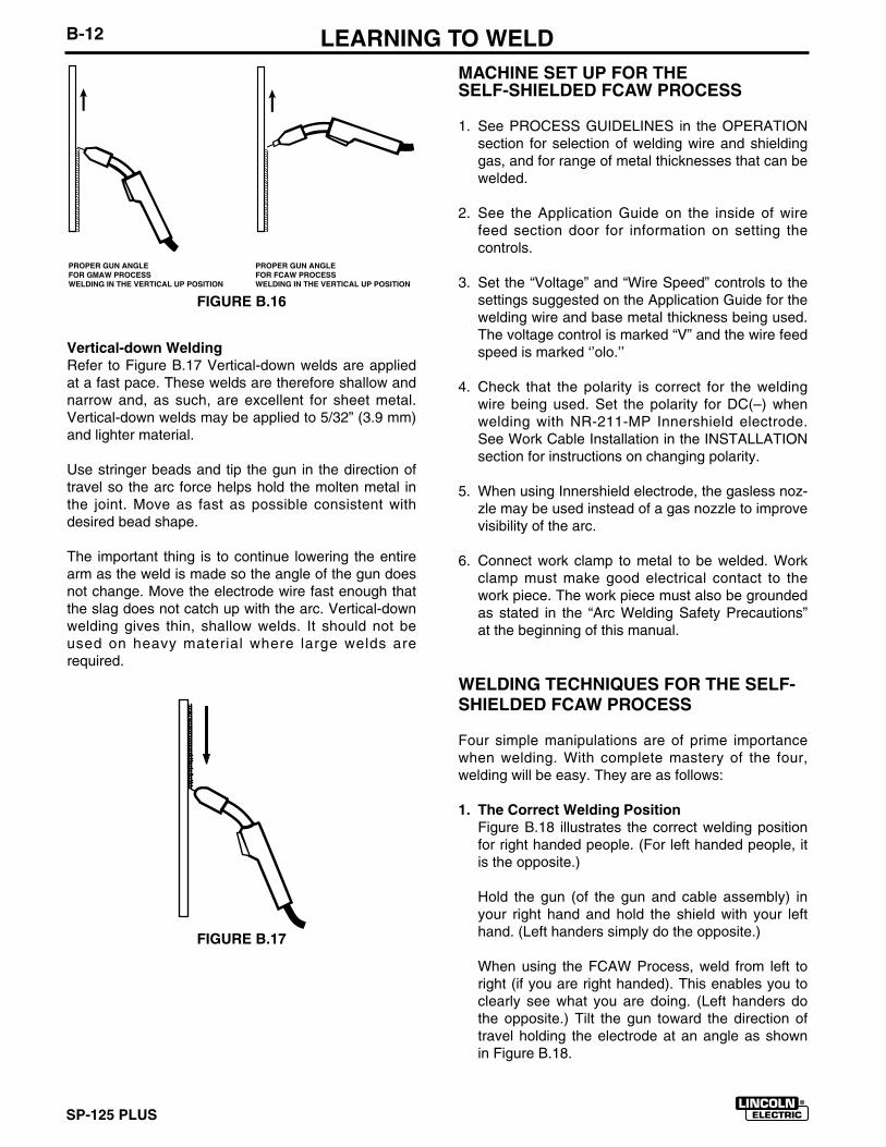
Vertical-down WeldingRefer to Figure B.17 Vertical-down welds are appliedat a fast pace. These welds are therefore shallow andnarrow and, as such, are excellent for sheet metal.Vertical-down welds may be applied to 5/32” (3.9 mm)and lighter material.
Use stringer beads and tip the gun in the direction oftravel so the arc force helps hold the molten metal inthe joint. Move as fast as possible consistent withdesired bead shape.
The important thing is to continue lowering the entirearm as the weld is made so the angle of the gun doesnot change. Move the electrode wire fast enough thatthe slag does not catch up with the arc. Vertical-downwelding gives thin, shallow welds. It should not beused on heavy material where large welds arerequired.
FIGURE B.17
PROPER GUN ANGLEFOR GMAW PROCESSWELDING IN THE VERTICAL UP POSITION
PROPER GUN ANGLEFOR FCAW PROCESSWELDING IN THE VERTICAL UP POSITION
MACHINE SET UP FOR THE SELF-SHIELDED FCAW PROCESS
1. See PROCESS GUIDELINES in the OPERATIONsection for selection of welding wire and shieldinggas, and for range of metal thicknesses that can bewelded.
2. See the Application Guide on the inside of wirefeed section door for information on setting thecontrols.
3. Set the “Voltage” and “Wire Speed” controls to thesettings suggested on the Application Guide for thewelding wire and base metal thickness being used.The voltage control is marked “V” and the wire feedspeed is marked ‘’olo.’’
4. Check that the polarity is correct for the weldingwire being used. Set the polarity for DC(–) whenwelding with NR-211-MP Innershield electrode.See Work Cable Installation in the INSTALLATIONsection for instructions on changing polarity.
5. When using Innershield electrode, the gasless noz-zle may be used instead of a gas nozzle to improvevisibility of the arc.
6. Connect work clamp to metal to be welded. Workclamp must make good electrical contact to thework piece. The work piece must also be groundedas stated in the “Arc Welding Safety Precautions”at the beginning of this manual.
WELDING TECHNIQUES FOR THE SELF-SHIELDED FCAW PROCESS
Four simple manipulations are of prime importancewhen welding. With complete mastery of the four,welding will be easy. They are as follows:
1. The Correct Welding PositionFigure B.18 illustrates the correct welding positionfor right handed people. (For left handed people, itis the opposite.)
Hold the gun (of the gun and cable assembly) inyour right hand and hold the shield with your lefthand. (Left handers simply do the opposite.)
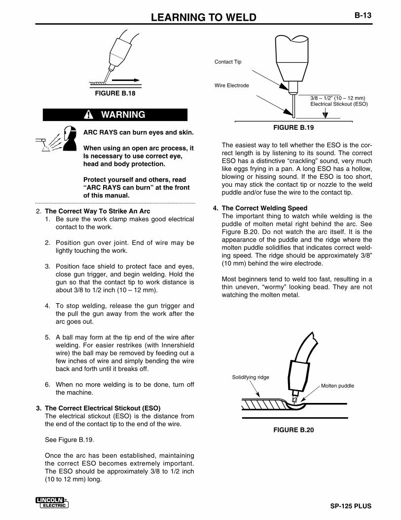
When using the FCAW Process, weld from left toright (if you are right handed). This enables you toclearly see what you are doing. (Left handers dothe opposite.) Tilt the gun toward the direction oftravel holding the electrode at an angle as shownin Figure B.18.
SP-125 PLUS
B-13 LEARNING TO WELD
ARC RAYS can burn eyes and skin.
When using an open arc process, itIs necessary to use correct eye,head and body protection.
Protect yourself and others, read“ARC RAYS can burn” at the frontof this manual.
2. The Correct Way To Strike An Arc1. Be sure the work clamp makes good electrical
contact to the work.
2. Position gun over joint. End of wire may belightly touching the work.
3. Position face shield to protect face and eyes,close gun trigger, and begin welding. Hold thegun so that the contact tip to work distance isabout 3/8 to 1/2 inch (10 – 12 mm).
4. To stop welding, release the gun trigger andthe pull the gun away from the work after thearc goes out.
5. A ball may form at the tip end of the wire afterwelding. For easier restrikes (with Innershieldwire) the ball may be removed by feeding out afew inches of wire and simply bending the wireback and forth until it breaks off.
6. When no more welding is to be done, turn offthe machine.
3. The Correct Electrical Stickout (ESO)The electrical stickout (ESO) is the distance fromthe end of the contact tip to the end of the wire.
See Figure B.19.
Once the arc has been established, maintainingthe correct ESO becomes extremely important.The ESO should be approximately 3/8 to 1/2 inch(10 to 12 mm) long.
FIGURE B.20
FIGURE B.18
WARNINGFIGURE B.19
3/8 – 1/2” (10 – 12 mm)Electrical Stickout (ESO)
Contact Tip
Wire Electrode
Solidifying ridge
Molten puddle
The easiest way to tell whether the ESO is the cor-rect length is by listening to its sound. The correctESO has a distinctive “crackling” sound, very muchlike eggs frying in a pan. A long ESO has a hollow,blowing or hissing sound. If the ESO is too short,you may stick the contact tip or nozzle to the weldpuddle and/or fuse the wire to the contact tip.
4. The Correct Welding SpeedThe important thing to watch while welding is thepuddle of molten metal right behind the arc. SeeFigure B.20. Do not watch the arc itself. It is theappearance of the puddle and the ridge where themolten puddle solidifies that indicates correct weld-ing speed. The ridge should be approximately 3/8”(10 mm) behind the wire electrode.
Most beginners tend to weld too fast, resulting in athin uneven, “wormy” looking bead. They are notwatching the molten metal.
SP-125 PLUS
B-14 LEARNING TO WELD
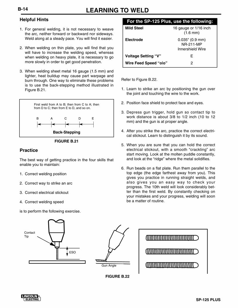
Mild Steel 16 gauge or 1/16 inch(1.6 mm)
Electrode 0.035" (0.9 mm)NR-211-MP
Innershield Wire
Voltage Setting “V” E
Wire Feed Speed “o|o” 2
For the SP-125 Plus, use the following:Helpful Hints
1. For general welding, it is not necessary to weavethe arc, neither forward or backward nor sideways.Weld along at a steady pace. You will find it easier.
2. When welding on thin plate, you will find that youwill have to increase the welding speed, whereaswhen welding on heavy plate, it is necessary to gomore slowly in order to get good penetration.
3. When welding sheet metal 16 gauge (1.5 mm) andlighter, heat buildup may cause part warpage andburn through. One way to eliminate these problemsis to use the back-stepping method illustrated inFigure B.21.
FIGURE B.21
Practice
The best way of getting practice in the four skills thatenable you to maintain:
1. Correct welding position
2. Correct way to strike an arc
3. Correct electrical stickout
4. Correct welding speed
is to perform the following exercise.
Refer to Figure B.22.
1. Learn to strike an arc by positioning the gun overthe joint and touching the wire to the work.
2. Position face shield to protect face and eyes.
3. Depress gun trigger, hold gun so contact tip towork distance is about 3/8 to 1/2 inch (10 to 12mm) and the gun is at proper angle.
4. After you strike the arc, practice the correct electri-cal stickout. Learn to distinguish it by its sound.
5. When you are sure that you can hold the correctelectrical stickout, with a smooth “crackling” arcstart moving. Look at the molten puddle constantly,and look at the “ridge” where the metal solidifies.
6. Run beads on a flat plate. Run them parallel to thetop edge (the edge farthest away from you). Thisgives you practice in running straight welds, andalso gives you an easy way to check yourprogress. The 10th weld will look considerably bet-ter than the first weld. By constantly checking onyour mistakes and your progress, welding will soonbe a matter of routine.
First weld from A to B; then from C to A; thenfrom D to C; then from E to D, and so on.
B A C D E
Back-Stepping
FIGURE B.22
ContactTip
Gun Angle
ESO
SP-125 PLUS
B-15 LEARNING TO WELDMACHINE SET UP FOR THE GMAW (MIG)PROCESS
1. See PROCESS GUIDELINES in the OPERATIONsection for selection of welding wire and shieldinggas, and for range of metal thicknesses that can bewelded.
2. See the Application Guide on the inside of wirefeed section door for information on setting thecontrols.
3. Set the “Voltage” and “Wire Speed” controls to thesettings suggested on the Application Guide for thewelding wire and base metal thickness being used.The voltage control is marked “V” and the wire feedspeed is marked ‘’olo.’’
4. Check that the polarity is correct for the weldingwire being used. Set the polarity for DC(+) whenwelding with the GMAW (MIG) process. See WorkCable Installation in the INSTALLATION section forinstructions for changing polarity.
5. Check that the gas nozzle and proper size linerand contact tip are being used and that the gassupply is turned on. If adjustable, set for 15 to 20cubic feet per hour (7 to 10 l/min.) under normalconditions, increase to as high as 35 CFH (17I/min.) under drafty (slightly windy) conditions.
6. Connect work clamp to metal to be welded. Workclamp must make good electrical contact to thework piece. The work piece must also be groundedas stated in the “Arc Welding Safety Precautions”at the beginning of this manual.
WELDING TECHNIQUES FOR THE GMAW(MIG) PROCESS
Four simple manipulations are of prime importancewhen welding. With complete mastery of the four,welding will be easy. They are as follows:
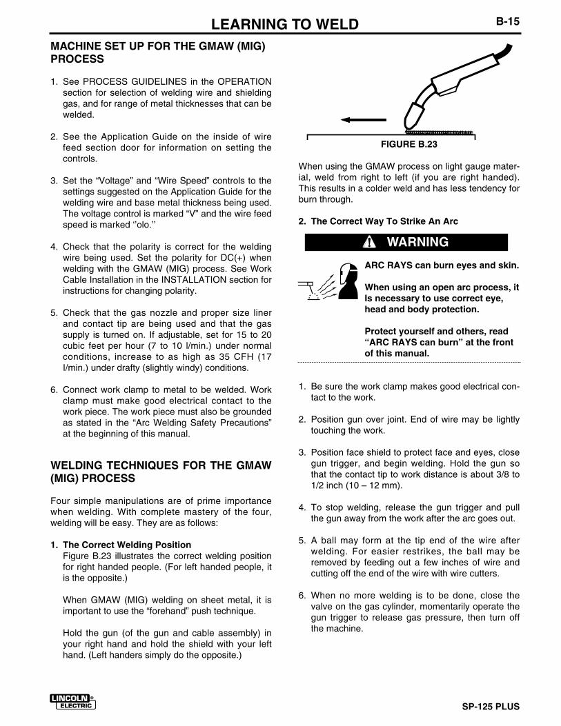
1. The Correct Welding PositionFigure B.23 illustrates the correct welding positionfor right handed people. (For left handed people, itis the opposite.)
When GMAW (MIG) welding on sheet metal, it isimportant to use the “forehand” push technique.
Hold the gun (of the gun and cable assembly) inyour right hand and hold the shield with your lefthand. (Left handers simply do the opposite.)
FIGURE B.23
When using the GMAW process on light gauge mater-ial, weld from right to left (if you are right handed).This results in a colder weld and has less tendency forburn through.
2. The Correct Way To Strike An Arc
ARC RAYS can burn eyes and skin.
When using an open arc process, itIs necessary to use correct eye,head and body protection.
Protect yourself and others, read“ARC RAYS can burn” at the frontof this manual.
1. Be sure the work clamp makes good electrical con-tact to the work.
2. Position gun over joint. End of wire may be lightlytouching the work.
3. Position face shield to protect face and eyes, closegun trigger, and begin welding. Hold the gun sothat the contact tip to work distance is about 3/8 to1/2 inch (10 – 12 mm).
4. To stop welding, release the gun trigger and pullthe gun away from the work after the arc goes out.
5. A ball may form at the tip end of the wire afterwelding. For easier restrikes, the ball may beremoved by feeding out a few inches of wire andcutting off the end of the wire with wire cutters.
6. When no more welding is to be done, close thevalve on the gas cylinder, momentarily operate thegun trigger to release gas pressure, then turn offthe machine.
WARNING
Helpful Hints
1. For general welding, it is not necessary to weavethe arc, neither forward or backward nor sideways.Weld along at a steady pace. You will find it easier.
2. When welding on thin plate, you will find that youwill have to increase the welding speed, whereaswhen welding on heavy plate, it is necessary to gomore slowly in order to get good penetration.
3. When welding sheet metal 16 gauge (1.5 mm) andlighter, heat buildup may cause part warpage andburn through. One way to eliminate these problemsis to use the back-stepping method illustrated inFigure B.21.
Practice
The best way of getting practice in the four skills thatenable you to maintain:
1. Correct welding position
2. Correct way to strike an arc
3. Correct electrical stickout
4. Correct welding speed
is to perform the following exercise.
Refer to Figure B.22.
1. Learn to strike an arc by positioning the gun overthe joint and touching the wire to the work.
2. Position face shield to protect face and eyes.
3. Depress gun trigger, hold gun so contact tip towork distance Is about 3/8 to 1/2 inch (10 to 12mm) and the gun is at proper angle.
SP-125 PLUS
B-16 LEARNING TO WELD
Mild Steel 16 gauge or 1/16 inch(1.6 mm)
Electrode Lincolnweld 0.025 L-56electrode
CO2
Voltage Setting “V” G
Wire Feed Speed “o|o” 5
For the SP-125 Plus, use the following:
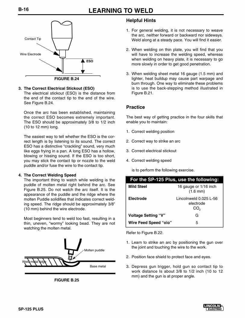
FIGURE B.24
3. The Correct Electrical Stickout (ESO)The electrical stickout (ESO) is the distance fromthe end of the contact tip to the end of the wire.See Figure B.24.
Once the arc has been established, maintainingthe correct ESO becomes extremely important.The ESO should be approximately 3/8 to 1/2 inch(10 to 12 mm) long.
The easiest way to tell whether the ESO is the cor-rect length is by listening to its sound. The correctESO has a distinctive “crackling” sound, very muchlike eggs frying in a pan. A long ESO has a hollow,blowing or hissing sound. If the ESO is too short,you may stick the contact tip or nozzle to the weldpuddle and/or fuse the wire to the contact tip.
4. The Correct Welding SpeedThe important thing to watch while welding is thepuddle of molten metal right behind the arc. SeeFigure B.25. Do not watch the arc itself. It is theappearance of the puddle and the ridge where themolten Puddle solidifies that indicates correct weld-ing speed. The ridge should be approximately 3/8”(10 mm) behind the wire electrode.
Most beginners tend to weld too fast, resulting in athin, uneven, “wormy” looking bead. They are notwatching the molten metal.
FIGURE B.25
Contact Tip
Wire Electrode
ESO
Molten puddle
Base metalWeld metal ridge
SP-125 PLUS
B-17LEARNING TO WELD4. After you strike the arc, practice the correct electri-
cal stickout. Learn to distinguish it by its sound.
5. When you are sure that you can hold the correctelectrical stickout, with a smooth “crackling” arc,start moving. Look at the molten puddle constantly.
6. Run beads on a flat plate. Run them parallel to thetop edge (the edge farthest away from you). Thisgives you practice in running straight welds, andalso gives you an easy way to check yourprogress. The 10th weld will look considerably bet-ter than the first weld. By constantly checking onyour mistakes and your progress, welding will soonbe a matter of routine.
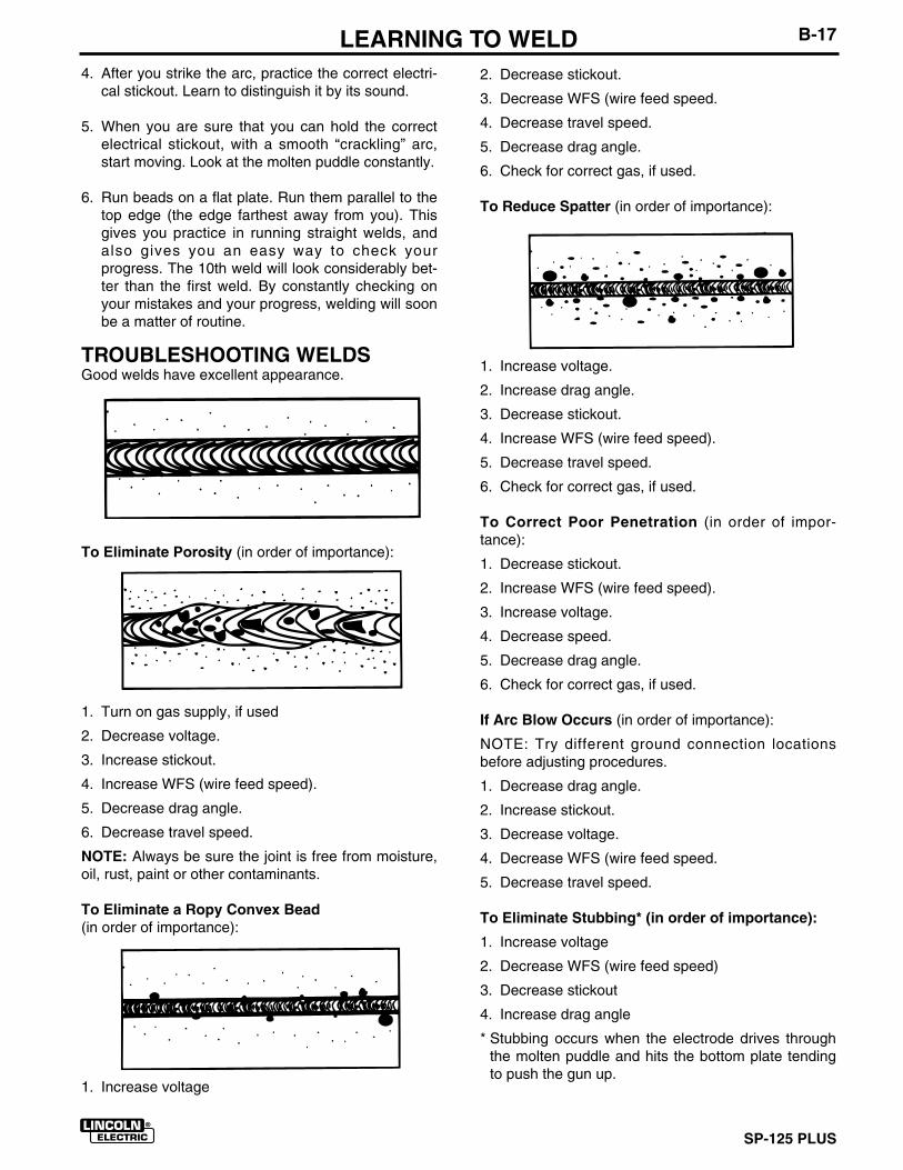
TROUBLESHOOTING WELDSGood welds have excellent appearance.
To Eliminate Porosity (in order of importance):
1. Turn on gas supply, if used
2. Decrease voltage.
3. Increase stickout.
4. Increase WFS (wire feed speed).
5. Decrease drag angle.
6. Decrease travel speed.
NOTE: Always be sure the joint is free from moisture,oil, rust, paint or other contaminants.
To Eliminate a Ropy Convex Bead(in order of importance):
1. Increase voltage
2. Decrease stickout.
3. Decrease WFS (wire feed speed.
4. Decrease travel speed.
5. Decrease drag angle.
6. Check for correct gas, if used.
To Reduce Spatter (in order of importance):
1. Increase voltage.
2. Increase drag angle.
3. Decrease stickout.
4. Increase WFS (wire feed speed).
5. Decrease travel speed.
6. Check for correct gas, if used.
To Correct Poor Penetration (in order of impor-tance):
1. Decrease stickout.
2. Increase WFS (wire feed speed).
3. Increase voltage.
4. Decrease speed.
5. Decrease drag angle.
6. Check for correct gas, if used.
If Arc Blow Occurs (in order of importance):
NOTE: Try different ground connection locationsbefore adjusting procedures.
1. Decrease drag angle.
2. Increase stickout.
3. Decrease voltage.
4. Decrease WFS (wire feed speed.
5. Decrease travel speed.
To Eliminate Stubbing* (in order of importance):
1. Increase voltage
2. Decrease WFS (wire feed speed)
3. Decrease stickout
4. Increase drag angle
* Stubbing occurs when the electrode drives throughthe molten puddle and hits the bottom plate tendingto push the gun up.

SP-125 PLUS
B-18 LEARNING TO WELDProper Gun Handling
Most feeding problems are caused by improper han-dling of the gun cable or electrodes.
1. Do not kink or pull the gun around sharp corners
2. Keep the gun cable as straight as practical whenwelding.
3. Do not allow dolly wheels or trucks to run over thecables.
4. Keep the cable clean.
5. Innershield electrode has proper surface lubrica-tion. Use only clean, rust-free electrode.
6. Replace contact tip when it becomes worn or theend is fused or deformed.
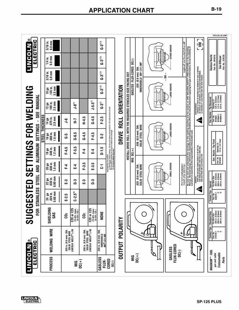
B-19 APPLICATION CHART
SP-125 PLUS
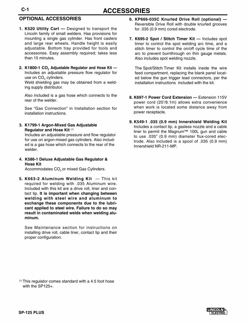
C-1
SP-125 PLUS
ACCESSORIES6. KP666-035C Knurled Drive Roll (optional) —
Reversible Drive Roll with double knurled groovesfor .035 (0.9 mm) cored electrode.
7. K695-2 Spot / Stitch Timer Kit — Includes spottimer to control the spot welding arc time, and astitch timer to control the on/off cycle time of thearc to prevent burnthrough on thin gauge metals.Also includes spot welding nozzle.
The Spot/Stitch Timer Kit installs inside the wirefeed compartment, replacing the blank panel locat-ed below the gun trigger lead connectors, per theinstallation instructions included with the kit.
8. K697-1 Power Cord Extension — Extension 115Vpower cord (20’/6.1m) allows extra conveniencewhen work is located some distance away frompower receptacle.
9. K549-1 .035 (0.9 mm) Innershield Welding KitIncludes a contact tip, a gasless nozzle and a cableliner to permit the Magnum™ 100L gun and cableto use .035” (0.9 mm) diameter flux-cored elec-trode. Also included is a spool of .035 (0.9 mm)Innershield NR-211-MP.
OPTIONAL ACCESSORIES
1. K520 Utility Cart — Designed to transport theLincoln family of small welders. Has provisions formounting a single gas cylinder. Has front castersand large rear wheels. Handle height is easilyadjustable. Bottom tray provided for tools andaccessories. Easy assembly required; takes lessthan 15 minutes.
2. K1800-1 CO2 Adjustable Regulator and Hose Kit —Includes an adjustable pressure flow regulator foruse on CO2 cylinders. Weld shielding gas may be obtained from a weld-ing supply distributor.
Also included is a gas hose which connects to therear of the welder.
See “Gas Connection” in Installation section forinstallation instructions.
3. K1799-1 Argon-Mixed Gas AdjustableRegulator and Hose Kit (1)
Includes an adjustable pressure and flow regulatorfor use on argon-mixed gas cylinders. Also includ-ed is a gas hose which connects to the rear of thewelder.
4. K586-1 Deluxe Adjustable Gas Regulator &Hose KitAccommodates CO2 or mixed Gas Cylinders.
5. K663-2 Aluminum Welding Kit — This kitrequired for welding with .035 Aluminum wire.Included with this kit are a drive roll, liner and con-tact tip. It is important when changing betweenwelding with steel wire and aluminum toexchange these components due to the lubri-cant applied to steel wire. Failure to do so mayresult in contaminated welds when welding alu-minum.
See Maintenance section for instructions oninstalling drive roll, cable liner, contact tip and theirproper configuration.
(1) This regulator comes standard with a 4.5 foot hosewith the SP125+.
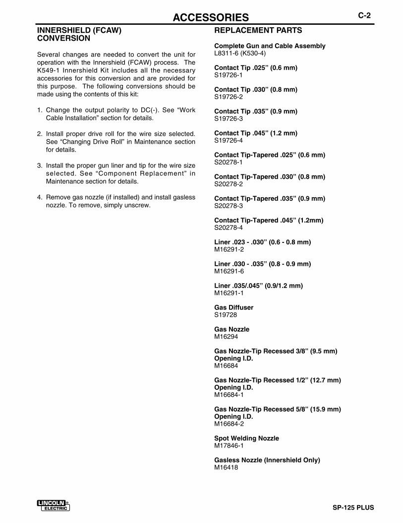
C-2
SP-125 PLUS
ACCESSORIESINNERSHIELD (FCAW)CONVERSION
Several changes are needed to convert the unit foroperation with the Innershield (FCAW) process. TheK549-1 Innershield Kit includes all the necessaryaccessories for this conversion and are provided forthis purpose. The following conversions should bemade using the contents of this kit:
1. Change the output polarity to DC(-). See “WorkCable Installation” section for details.
2. Install proper drive roll for the wire size selected.See “Changing Drive Roll” in Maintenance sectionfor details.
3. Install the proper gun liner and tip for the wire sizeselected. See “Component Replacement” inMaintenance section for details.
4. Remove gas nozzle (if installed) and install gaslessnozzle. To remove, simply unscrew.
REPLACEMENT PARTS
Complete Gun and Cable AssemblyL8311-6 (K530-4)
Contact Tip .025” (0.6 mm)S19726-1
Contact Tip .030” (0.8 mm)S19726-2
Contact Tip .035” (0.9 mm)S19726-3
Contact Tip .045” (1.2 mm)S19726-4
Contact Tip-Tapered .025” (0.6 mm)S20278-1
Contact Tip-Tapered .030” (0.8 mm)S20278-2
Contact Tip-Tapered .035” (0.9 mm)S20278-3
Contact Tip-Tapered .045” (1.2mm)S20278-4
Liner .023 - .030” (0.6 - 0.8 mm)M16291-2
Liner .030 - .035” (0.8 - 0.9 mm)M16291-6
Liner .035/.045” (0.9/1.2 mm)M16291-1
Gas DiffuserS19728
Gas NozzleM16294
Gas Nozzle-Tip Recessed 3/8” (9.5 mm) Opening I.D.M16684
Gas Nozzle-Tip Recessed 1/2” (12.7 mm) Opening I.D.M16684-1
Gas Nozzle-Tip Recessed 5/8” (15.9 mm) Opening I.D.M16684-2
Spot Welding NozzleM17846-1
Gasless Nozzle (Innershield Only)M16418
SP-125 PLUS
MAINTENANCE
SAFETY PRECAUTIONS
ELECTRIC SHOCK can kill.
• Disconnect input power by remov-ing plug from receptacle beforeworking inside SP-125 PLUS. Useonly grounded receptacle. Do nottouch electrically “hot” partsinside SP-125 PLUS.
• Have qualified personnel do themaintenance and trouble shootingwork.
ITEMS REQUIRING NO MAINTENANCE
• Drive Motor and Gearbox – Lifetime lubrication• Fan Motor- Lifetime lubrication.• Wire Reel Spindle – Do NOT lubricate shaft.
ROUTINE AND PERIODIC MAINTE-NANCE
BEFORE EACH USE• Check over machine and accessories for any obvious
condition that may prevent safe performance or oper-ation, repair or replace items as necessary to correctany abnormal condition.
AFTER 5 MINUTES OF WELDING or when spatter accumulates in nozzle
• Clean nozzle to avoid bridging between nozzle andcontact tip which results in shorted nozzle, poor weldsand overheated gun. Hint: Anti-stick spray or gelavailable from a welding supply distributor mayreduce buildup and aid in spatter removal.
AFTER EACH SPOOL OF WIRE FEED
• Remove contact tip and clean inside diameter withshort piece of wire
• Clean cable liner – when rough and erratic wire feed-ing occur.
MAINTENANCED-1
WARNING
AFTER FEEDING 50# OF FLUX COREDWIRE OR 300# OF SOLID WIRE
• Unplug machine or turn power switch to OFF – “O”position. Remove gun and cable from machine.
• Remove gas nozzle and contact tip from gun.
• Lay cable out straight - blow out gently into gun endwith compressed air. Bend cable back and forth –blow out again – Repeat until clean.
Excessive pressure at start may cause the dirt toform a plug.
PERIODICALLY AS REQUIRED
• Blow dirt out of the welder with low pressure air toeliminate excessive dirt and dust buildup that couldcause welder to run hot.
• Blow dirt out of: Rectifier & Fan Motor Assembly;PC Board located on Case Side Assembly; andCenter Assembly components.
• Vacuum accumulated dirt from gearbox and wirefeed section.
• Inspect the incoming guide tube and clean insidediameter if necessary. Replace when excessivelyworn.
• Replace Contact Tip – when hole is enlarged orelongated (refer to “CHANGING THE CONTACTTIP”, in this section).
• Replace gas nozzle.
• Replace Liner – when wire feeding problems occurand other items have been checked (refer to“CHANGING LINER” procedure in this section).
• Replace internal gun handle parts as necessary(see Procedure at the end of this section).
WARNING
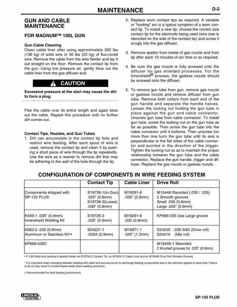
SP-125 PLUS
D-2 MAINTENANCE
GUN AND CABLE MAINTENANCE
FOR MAGNUM™ 100L GUN
Gun Cable CleaningClean cable liner after using approximately 300 lbs(136 kg) of solid wire or 50 lbs (23 kg) of flux-coredwire. Remove the cable from the wire feeder and lay itout straight on the floor. Remove the contact tip fromthe gun. Using low pressure air, gently blow out thecable liner from the gas diffuser end.
Excessive pressure at the start may cause the dirtto form a plug.
Flex the cable over its entire length and again blowout the cable. Repeat this procedure until no furtherdirt comes out.
Contact Tips, Nozzles, and Gun Tubes1. Dirt can accumulate in the contact tip hole and
restrict wire feeding. After each spool of wire isused, remove the contact tip and clean it by push-ing a short piece of wire through the tip repeatedly.Use the wire as a reamer to remove dirt that maybe adhering to the wall of the hole through the tip.
2. Replace worn contact tips as required. A variableor “hunting” arc is a typical symptom of a worn con-tact tip. To install a new tip, choose the correct sizecontact tip for the electrode being used (wire size isstenciled on the side of the contact tip) and screw itsnugly into the gas diffuser.
3. Remove spatter from inside of gas nozzle and fromtip after each 10 minutes of arc time or as required.
4. Be sure the gas nozzle is fully screwed onto thediffuser for gas shielded processes. For theInnershield® process, the gasless nozzle shouldbe screwed onto the diffuser.
5. To remove gun tube from gun, remove gas nozzleor gasless nozzle and remove diffuser from guntube. Remove both collars from each end of thegun handle and separate the handle halves.Loosen the locking nut holding the gun tube inplace against the gun end cable connector.Unscrew gun tube from cable connector. To installgun tube, screw the locking nut on the gun tube asfar as possible. Then screw the gun tube into thecable connector until it bottoms. Then unscrew (nomore than one turn) the gun tube until its axis isperpendicular to the flat sides of the cable connec-tor and pointed in the direction of the trigger.Tighten the locking nut so as to maintain the properrelationship between the gun tube and the cableconnector. Replace the gun handle, trigger and dif-fuser. Replace the gas nozzle or gasless nozzle.
CAUTION
CONFIGURATION OF COMPONENTS IN WIRE FEEDING SYSTEMContact Tip Cable Liner Drive Roll
Components shipped with S19726-1(In Gun) M16291-6 M15448 Stenciled (.030 / .035)SP-125 PLUS .025” (0.6mm) .035” (0.9mm) 2 Smooth grooves
S19726-2(Loose) Small .030 (0.8mm).030” (0.8mm) Large .035” (0.9mm)
K549-1 .035” (0.9mm) S19726-3 M16291-6 KP666-035 Use Large grooveInnershield Welding Kit .035” (0.9mm) .035 (0.9mm)
K663-2 .035 (0.9mm) S24221-1 M18971-1 S24220 .035-3/64 (Drive roll)Aluminum or Stainless Kit*• .035A (0.9mm) .045” (1.2mm) S24219 (Idle roll)
KP666-035C M15448-1 Stenciled2 Knurled grooves for .035” (0.9mm)
• If .030 Solid wire feeding is desired obtain an S19726-2 Contact Tip, an M16291-2 Cable Liner and an M15448 Drive Roll (Smaller Groove).
* It is important when changing between welding with steel wire and aluminum to exchange feeding components due to the lubricant applied to steel wire. Failureto do so may result in contaminated welds when welding aluminum.
Δ Recommended for best feeding performance.
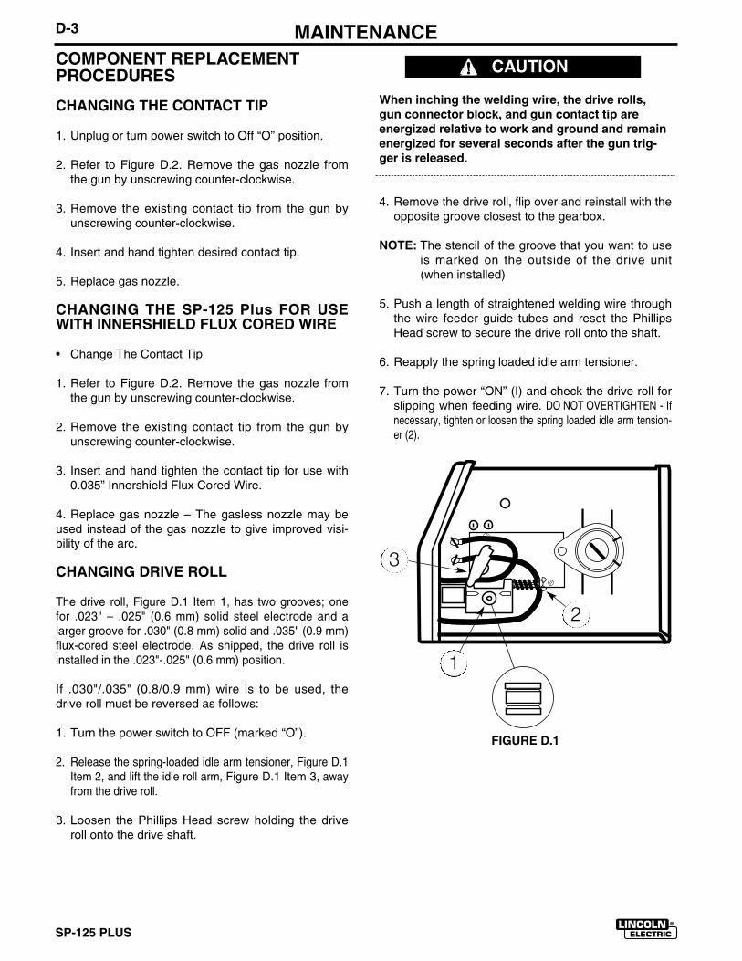
SP-125 PLUS
D-3 MAINTENANCECOMPONENT REPLACEMENT PROCEDURES
CHANGING THE CONTACT TIP
1. Unplug or turn power switch to Off “O” position.
2. Refer to Figure D.2. Remove the gas nozzle fromthe gun by unscrewing counter-clockwise.
3. Remove the existing contact tip from the gun byunscrewing counter-clockwise.
4. Insert and hand tighten desired contact tip.
5. Replace gas nozzle.
CHANGING THE SP-125 Plus FOR USEWITH INNERSHIELD FLUX CORED WIRE
• Change The Contact Tip
1. Refer to Figure D.2. Remove the gas nozzle fromthe gun by unscrewing counter-clockwise.
2. Remove the existing contact tip from the gun byunscrewing counter-clockwise.
3. Insert and hand tighten the contact tip for use with0.035” Innershield Flux Cored Wire.
4. Replace gas nozzle – The gasless nozzle may beused instead of the gas nozzle to give improved visi-bility of the arc.
CHANGING DRIVE ROLL
The drive roll, Figure D.1 Item 1, has two grooves; onefor .023" – .025" (0.6 mm) solid steel electrode and alarger groove for .030" (0.8 mm) solid and .035" (0.9 mm)flux-cored steel electrode. As shipped, the drive roll isinstalled in the .023"-.025" (0.6 mm) position.
If .030"/.035" (0.8/0.9 mm) wire is to be used, thedrive roll must be reversed as follows:
1. Turn the power switch to OFF (marked “O”).
2. Release the spring-loaded idle arm tensioner, Figure D.1Item 2, and lift the idle roll arm, Figure D.1 Item 3, awayfrom the drive roll.
3. Loosen the Phillips Head screw holding the driveroll onto the drive shaft.
When inching the welding wire, the drive rolls,gun connector block, and gun contact tip areenergized relative to work and ground and remainenergized for several seconds after the gun trig-ger is released.
4. Remove the drive roll, flip over and reinstall with theopposite groove closest to the gearbox.
NOTE: The stencil of the groove that you want to useis marked on the outside of the drive unit(when installed)
5. Push a length of straightened welding wire throughthe wire feeder guide tubes and reset the PhillipsHead screw to secure the drive roll onto the shaft.
6. Reapply the spring loaded idle arm tensioner.
7. Turn the power “ON” (I) and check the drive roll forslipping when feeding wire. DO NOT OVERTIGHTEN - Ifnecessary, tighten or loosen the spring loaded idle arm tension-er (2).
FIGURE D.1
CAUTION
3
2
1
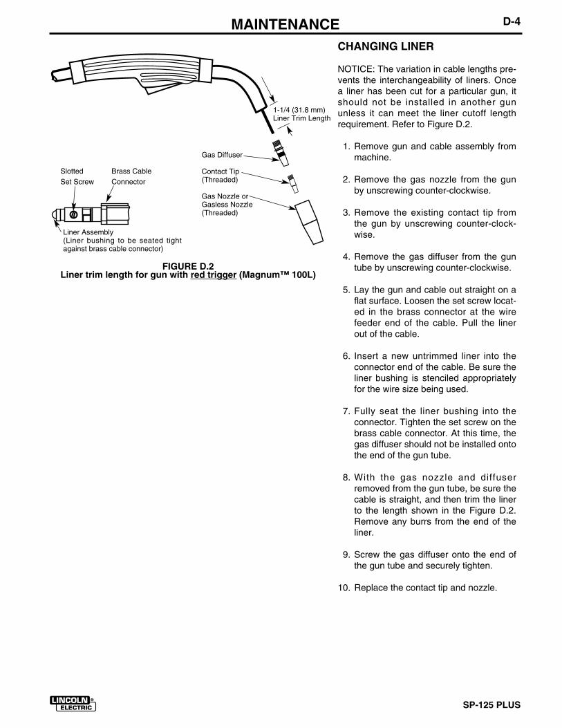
SP-125 PLUS
D-4MAINTENANCECHANGING LINER
NOTICE: The variation in cable lengths pre-vents the interchangeability of liners. Oncea liner has been cut for a particular gun, itshould not be installed in another gununless it can meet the liner cutoff lengthrequirement. Refer to Figure D.2.
1. Remove gun and cable assembly frommachine.
2. Remove the gas nozzle from the gunby unscrewing counter-clockwise.
3. Remove the existing contact tip fromthe gun by unscrewing counter-clock-wise.
4. Remove the gas diffuser from the guntube by unscrewing counter-clockwise.
5. Lay the gun and cable out straight on aflat surface. Loosen the set screw locat-ed in the brass connector at the wirefeeder end of the cable. Pull the linerout of the cable.
6. Insert a new untrimmed liner into theconnector end of the cable. Be sure theliner bushing is stenciled appropriatelyfor the wire size being used.
7. Fully seat the liner bushing into theconnector. Tighten the set screw on thebrass cable connector. At this time, thegas diffuser should not be installed ontothe end of the gun tube.
8. With the gas nozzle and diffuserremoved from the gun tube, be sure thecable is straight, and then trim the linerto the length shown in the Figure D.2.Remove any burrs from the end of theliner.
9. Screw the gas diffuser onto the end ofthe gun tube and securely tighten.
10. Replace the contact tip and nozzle.
1-1/4 (31.8 mm)Liner Trim Length
Gas Diffuser
Contact Tip(Threaded)
Gas Nozzle orGasless Nozzle(Threaded)
Liner Assembly (Liner bushing to be seated tightagainst brass cable connector)
FIGURE D.2Liner trim length for gun with red trigger (Magnum™ 100L)
Slotted Brass CableSet Screw Connector
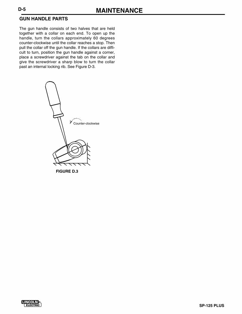
SP-125 PLUS
D-5 MAINTENANCEGUN HANDLE PARTS
The gun handle consists of two halves that are heldtogether with a collar on each end. To open up thehandle, turn the collars approximately 60 degreescounter-clockwise until the collar reaches a stop. Thenpull the collar off the gun handle. If the collars are diffi-cult to turn, position the gun handle against a corner,place a screwdriver against the tab on the collar andgive the screwdriver a sharp blow to turn the collarpast an internal locking rib. See Figure D-3.
FIGURE D.3➣
Counter-clockwise
SP-125 PLUS
E-1 TROUBLESHOOTING
Step 1. LOCATE PROBLEM (SYMPTOM).Look under the column labeled “PROBLEM(SYMPTOMS)”. This column describes pos-sible symptoms that the machine mayexhibit. Find the listing that best describesthe symptom that the machine is exhibiting.
Symptoms are grouped into the followingcategories: Output Problems; FeedingProblems; Gas Flow Problems; andWelding Problems.
Step 2. PERFORM EXTERNAL TESTS.The second column labeled “POSSIBLEAREAS OF MISADJUSTMENT(S)” lists theobvious external possibilities that may con-tribute to the machine symptom. Performthese tests/checks in the order listed. Ingeneral, these tests can be conducted with-out removing the case wrap-around cover.
Step 3. PERFORM COMPONENT TESTS.If you have exhausted all of the recom-mended tests in Step 2, consult your localAuthorized Field Service facility.
HOW TO USE TROUBLESHOOTING GUIDE
Service and Repair should only be performed by Lincoln Electric Factory Trained Personnel.Unauthorized repairs performed on this equipment may result in danger to the technician andmachine operator and will invalidate your factory warranty. For your safety and to avoidElectrical Shock, please observe all safety notes and precautions detailed throughout thismanual.__________________________________________________________________________
WARNING
If for any reason you do not understand the test procedures or are unable to Performthe tests/repairs safely, contact your LOCAL AUTHORIZED LINCOLN ELECTRICFIELD SERVICE FACILITY for assistance before you proceed.___________________________________________________________________
If machine case sides and top are removed, the case front must be supported.Failure to do this could result in mechanical or electrical damage to the SP-125 Plus.___________________________________________________________________
CAUTION
CAUTION
This Troubleshooting Guide is provided tohelp you locate and remedy possiblemachine problems. Simply follow the three-step procedure listed below.
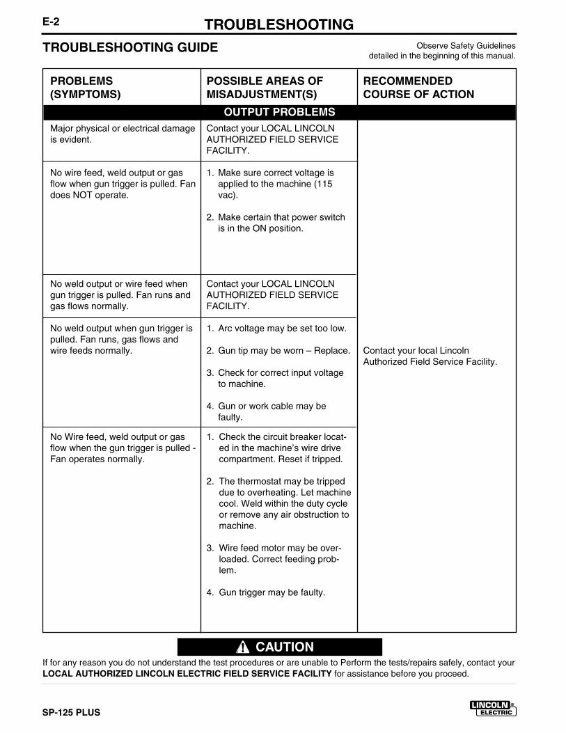
SP-125 PLUS
E-2 TROUBLESHOOTINGObserve Safety Guidelines
detailed in the beginning of this manual.TROUBLESHOOTING GUIDE
PROBLEMS(SYMPTOMS)
Major physical or electrical damageis evident.
No wire feed, weld output or gasflow when gun trigger is pulled. Fandoes NOT operate.
No weld output or wire feed whengun trigger is pulled. Fan runs andgas flows normally.
No weld output when gun trigger ispulled. Fan runs, gas flows andwire feeds normally.
No Wire feed, weld output or gasflow when the gun trigger is pulled -Fan operates normally.
POSSIBLE AREAS OFMISADJUSTMENT(S)
Contact your LOCAL LINCOLNAUTHORIZED FIELD SERVICEFACILITY.
1. Make sure correct voltage isapplied to the machine (115vac).
2. Make certain that power switchis in the ON position.
Contact your LOCAL LINCOLNAUTHORIZED FIELD SERVICEFACILITY.
1. Arc voltage may be set too low.
2. Gun tip may be worn – Replace.
3. Check for correct input voltageto machine.
4. Gun or work cable may befaulty.
1. Check the circuit breaker locat-ed in the machine’s wire drivecompartment. Reset if tripped.
2. The thermostat may be trippeddue to overheating. Let machinecool. Weld within the duty cycleor remove any air obstruction tomachine.
3. Wire feed motor may be over-loaded. Correct feeding prob-lem.
4. Gun trigger may be faulty.
RECOMMENDEDCOURSE OF ACTION
Contact your local LincolnAuthorized Field Service Facility.
OUTPUT PROBLEMS
If for any reason you do not understand the test procedures or are unable to Perform the tests/repairs safely, contact yourLOCAL AUTHORIZED LINCOLN ELECTRIC FIELD SERVICE FACILITY for assistance before you proceed.
CAUTION
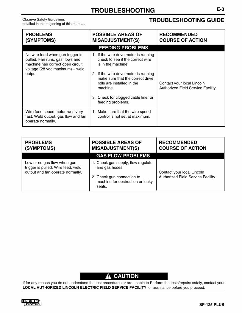
SP-125 PLUS
E-3TROUBLESHOOTINGObserve Safety Guidelinesdetailed in the beginning of this manual.
TROUBLESHOOTING GUIDE
PROBLEMS(SYMPTOMS)
No wire feed when gun trigger ispulled. Fan runs, gas flows andmachine has correct open circuitvoltage (28 vdc maximum) – weldoutput.
Wire feed speed motor runs veryfast. Weld output, gas flow and fanoperate normally.
POSSIBLE AREAS OFMISADJUSTMENT(S)
1. If the wire drive motor is runningcheck to see if the correct wireis in the machine.
2. If the wire drive motor is runningmake sure that the correct driverolls are installed in themachine.
3. Check for clogged cable liner orfeeding problems.
1. Make sure that the wire speedcontrol is not set at maximum.
RECOMMENDEDCOURSE OF ACTION
Contact your local LincolnAuthorized Field Service Facility.
FEEDING PROBLEMS
PROBLEMS(SYMPTOMS)
Low or no gas flow when guntrigger is pulled. Wire feed, weldoutput and fan operate normally.
POSSIBLE AREAS OFMISADJUSTMENT(S)
1. Check gas supply, flow regulatorand gas hoses.
2. Check gun connection tomachine for obstruction or leakyseals.
RECOMMENDEDCOURSE OF ACTION
Contact your local LincolnAuthorized Field Service Facility.
GAS FLOW PROBLEMS
If for any reason you do not understand the test procedures or are unable to Perform the tests/repairs safely, contact yourLOCAL AUTHORIZED LINCOLN ELECTRIC FIELD SERVICE FACILITY for assistance before you proceed.
CAUTION
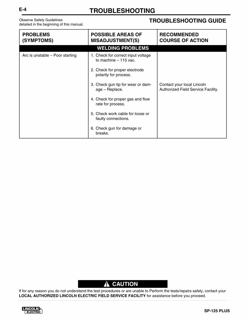
SP-125 PLUS
E-4 TROUBLESHOOTINGObserve Safety Guidelinesdetailed in the beginning of this manual.
TROUBLESHOOTING GUIDE
PROBLEMS(SYMPTOMS)
Arc is unstable – Poor starting
POSSIBLE AREAS OFMISADJUSTMENT(S)
1. Check for correct input voltageto machine – 115 vac.
2. Check for proper electrodepolarity for process.
3. Check gun tip for wear or dam-age – Replace.
4. Check for proper gas and flowrate for process.
5. Check work cable for loose orfaulty connections.
6. Check gun for damage orbreaks.
RECOMMENDEDCOURSE OF ACTION
Contact your local LincolnAuthorized Field Service Facility.
WELDING PROBLEMS
If for any reason you do not understand the test procedures or are unable to Perform the tests/repairs safely, contact yourLOCAL AUTHORIZED LINCOLN ELECTRIC FIELD SERVICE FACILITY for assistance before you proceed.
CAUTION
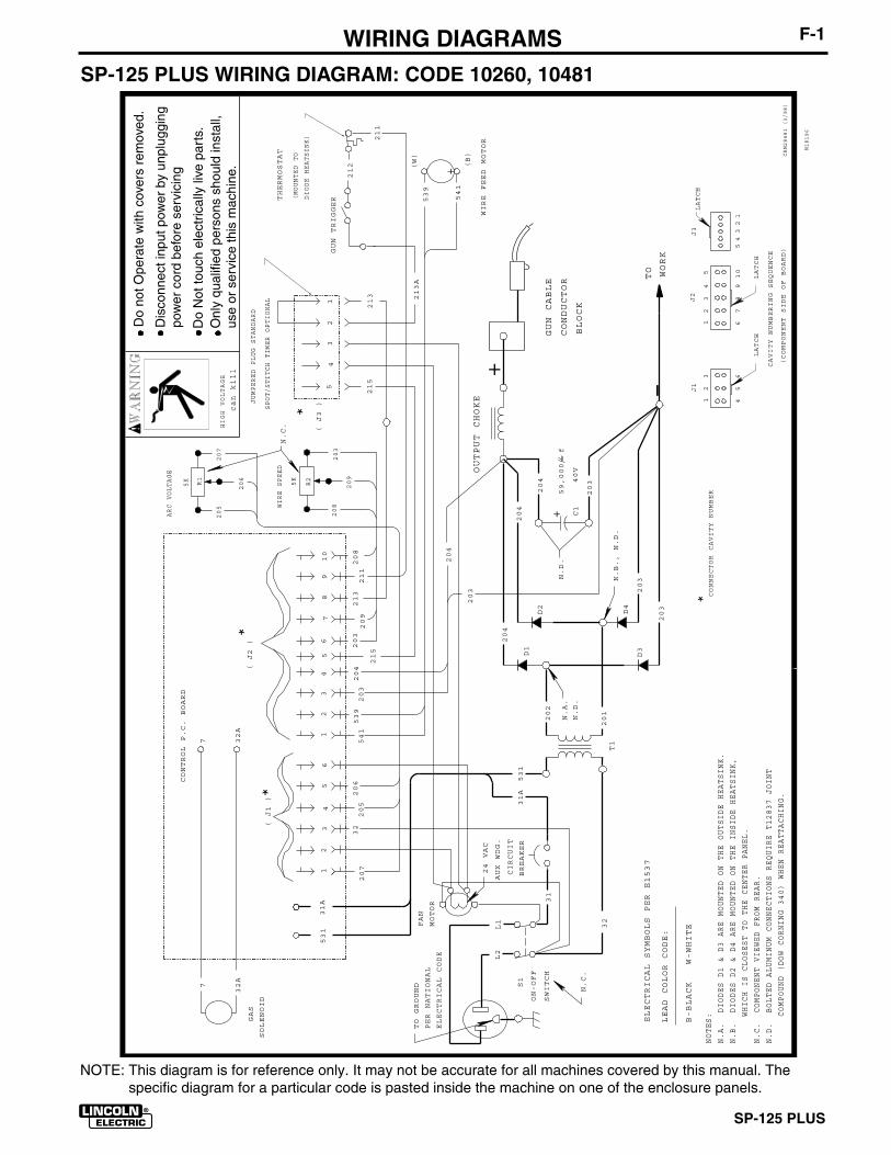
SP-125 PLUS
F-1 WIRING DIAGRAMSSP-125 PLUS WIRING DIAGRAM: CODE 10260, 10481
M18196
L1
L2
31
32
531
TO GROUND
PER NATIONAL
ELECTRICAL CODE
S1
SWITCH
202
201
D1
D3
D2
D4
204
204
204
203
203
203
C1
59,000 f
40V
203
204
-
+OUTPUT CHOKE
GUN CABLE
CONDUCTOR
BLOCK
TO WORK
ELECTRICAL SYMBOLS PER E1537
CIRCUIT
BREAKER
31A
12
3
45
6
LATCH
FAN
MOTOR
12
34
LATCH
5
67
89
10
J1
J2
CAVITY NUMBERING SEQUENCE
12
34
56
12
34
56
78
910
GAS
SOLENOID
7
32A
CONTROL P.C. BOARD
539
541
207
205
206
541
539
203
204
203209
213
208
211
531
31A
T1
WIRE FEED MOTOR
212
213A
211
GUN TRIGGERTHERMOSTAT
(MOUNTED TO
DIODE HEATSINK)
+
208
209
203
5K
WIRE SPEED
205
206
207
5K
32( J1 )
( J2 )
*
*
*CONNECTOR CAVITY NUMBER
ARC VOLTAGE
R1
R2
(W)
(B)
7 32A
N.A.
N.C.
ON-OFF
N.C.
N.D.
N.D.
24 VAC
AUX WDG.
+
NOTES:
N.A. DIODES D1 & D3 ARE MOUNTED ON THE OUTSIDE HEATSINK.
N.C. COMPONENT VIEWED FROM REAR.
HIGH VOLTAGE
can kill
N.B. DIODES D2 & D4 ARE MOUNTED ON THE INSIDE HEATSINK,
WHICH IS CLOSEST TO THE CENTER PANEL.
LEAD COLOR CODE:
B-BLACK W-WHITE
N.B., N.D.
(COMPONENT SIDE OF BOARD)
N.D. BOLTED ALUMINUM CONNECTIONS REQUIRE T12837 JOINT
COMPOUND (DOW CORNING 340) WHEN REATTACHING.
CRM28481 (3/98)
12
34
5
LATCH
J3
54
32
1
JUMPERED PLUG STANDARD
SPOT/STITCH TIMER OPTIONAL
215
215
213
( J3 )*
Do
not O
pera
te w
ith c
over
s re
mov
ed.
Dis
conn
ect i
nput
pow
er b
y un
plug
ging
pow
er c
ord
befo
re s
ervi
cing
Do
Not
touc
h el
ectr
ical
ly li
ve p
arts
.O
nly
qual
ified
per
sons
sho
uld
inst
all,
use
or s
ervi
ce th
is m
achi
ne.
NOTE: This diagram is for reference only. It may not be accurate for all machines covered by this manual. Thespecific diagram for a particular code is pasted inside the machine on one of the enclosure panels.

SP-125 PLUS
F-2 NOTES

SP-125 PLUS
NOTES
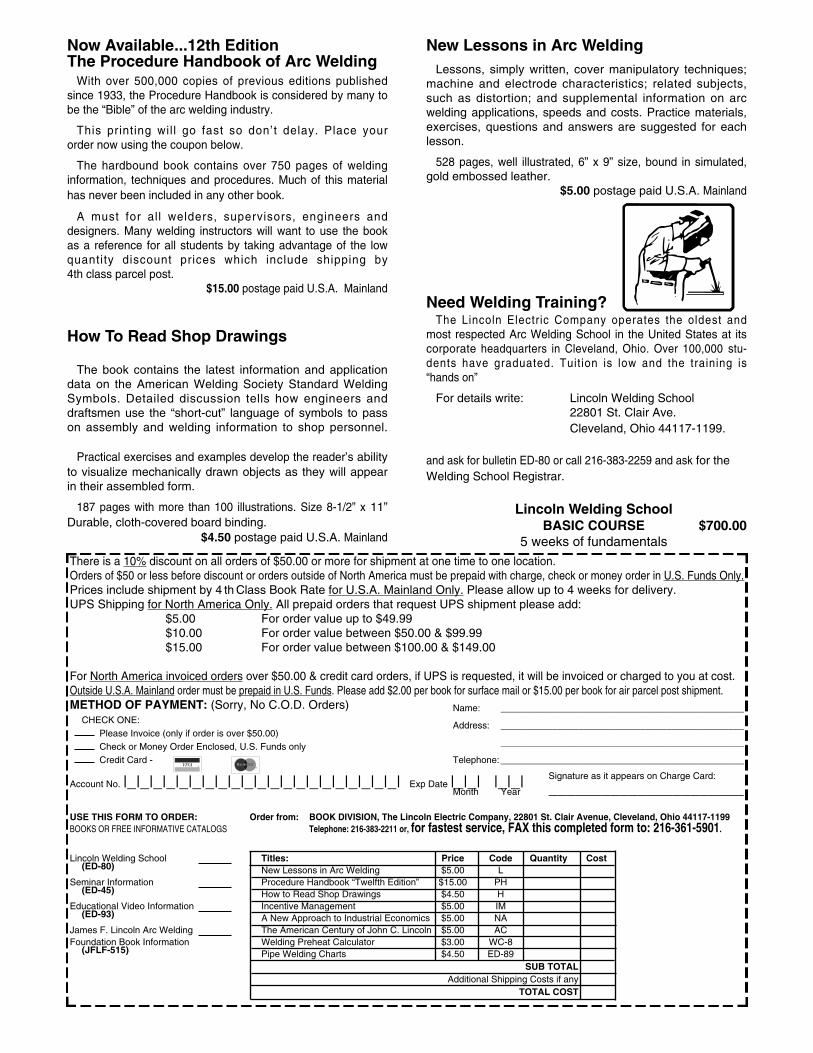
Now Available...12th EditionThe Procedure Handbook of Arc Welding
With over 500,000 copies of previous editions publishedsince 1933, the Procedure Handbook is considered by many to be the “Bible” of the arc welding industry.
This printing wil l go fast so don’t delay. Place your order now using the coupon below.
The hardbound book contains over 750 pages of weldinginformation, techniques and procedures. Much of this material has never been included in any other book.
A must for al l welders, supervisors, engineers anddesigners. Many welding instructors will want to use the bookas a reference for all students by taking advantage of the lowquantity discount prices which include shipping by4th class parcel post.
$15.00 postage paid U.S.A. Mainland
How To Read Shop Drawings
The book contains the latest information and applicationdata on the American Welding Society Standard WeldingSymbols. Detailed discussion tells how engineers anddraftsmen use the “short-cut” language of symbols to passon assembly and welding information to shop personnel.
Practical exercises and examples develop the reader’s abilityto visualize mechanically drawn objects as they will appearin their assembled form.
187 pages with more than 100 illustrations. Size 8-1/2” x 11”Durable, cloth-covered board binding.
$4.50 postage paid U.S.A. Mainland
New Lessons in Arc WeldingLessons, simply written, cover manipulatory techniques;
machine and electrode characteristics; related subjects,such as distortion; and supplemental information on arcwelding applications, speeds and costs. Practice materials,exercises, questions and answers are suggested for each lesson.
528 pages, well illustrated, 6” x 9” size, bound in simulated,gold embossed leather.
$5.00 postage paid U.S.A. Mainland
Need Welding Training?The Lincoln Electric Company operates the oldest and
most respected Arc Welding School in the United States at itscorporate headquarters in Cleveland, Ohio. Over 100,000 stu-dents have graduated. Tuit ion is low and the training is “hands on”
For details write: Lincoln Welding School22801 St. Clair Ave. Cleveland, Ohio 44117-1199.
and ask for bulletin ED-80 or call 216-383-2259 and ask for theWelding School Registrar.
Lincoln Welding SchoolBASIC COURSE $700.00
5 weeks of fundamentalsThere is a 10% discount on all orders of $50.00 or more for shipment at one time to one location.Orders of $50 or less before discount or orders outside of North America must be prepaid with charge, check or money order in U.S. Funds Only.Prices include shipment by 4 th Class Book Rate for U.S.A. Mainland Only. Please allow up to 4 weeks for delivery.UPS Shipping for North America Only. All prepaid orders that request UPS shipment please add:
$5.00 For order value up to $49.99$10.00 For order value between $50.00 & $99.99$15.00 For order value between $100.00 & $149.00
For North America invoiced orders over $50.00 & credit card orders, if UPS is requested, it will be invoiced or charged to you at cost.Outside U.S.A. Mainland order must be prepaid in U.S. Funds. Please add $2.00 per book for surface mail or $15.00 per book for air parcel post shipment.METHOD OF PAYMENT: (Sorry, No C.O.D. Orders)
CHECK ONE:Name: _______________________________________________
Please Invoice (only if order is over $50.00)Address: _______________________________________________
Check or Money Order Enclosed, U.S. Funds only _______________________________________________
Credit Card - Telephone: _______________________________________________
Signature as it appears on Charge Card:Account No. |_|_|_|_|_|_|_|_|_|_|_|_|_|_|_|_|_|_|_|_|_| Exp Date |_|_| |_|_| ______________________Month Year
USE THIS FORM TO ORDER: Order from: BOOK DIVISION, The Lincoln Electric Company, 22801 St. Clair Avenue, Cleveland, Ohio 44117-1199BOOKS OR FREE INFORMATIVE CATALOGS Telephone: 216-383-2211 or, for fastest service, FAX this completed form to: 216-361-5901.
Lincoln Welding School Titles: Price Code Quantity Cost(ED-80) New Lessons in Arc Welding $5.00 L
Seminar Information Procedure Handbook “Twelfth Edition” $15.00 PH(ED-45) How to Read Shop Drawings $4.50 H
Educational Video Information Incentive Management $5.00 IM(ED-93) A New Approach to Industrial Economics $5.00 NA
James F. Lincoln Arc Welding The American Century of John C. Lincoln $5.00 ACFoundation Book Information Welding Preheat Calculator $3.00 WC-8
(JFLF-515) Pipe Welding Charts $4.50 ED-89SUB TOTAL
Additional Shipping Costs if anyTOTAL COST
MasterCard
VISA ®
AMERICAN EXPRESS
MasterCardMasterCard®
AMERICAN EXPRESS
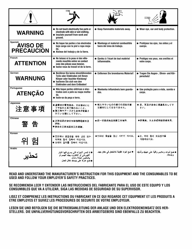
WARNING
AVISO DEPRECAUCION
ATTENTION
WARNUNG
ATENÇÃO
Spanish
French
German
Portuguese
Japanese
Chinese
Korean
Arabic
READ AND UNDERSTAND THE MANUFACTURER’S INSTRUCTION FOR THIS EQUIPMENT AND THE CONSUMABLES TO BEUSED AND FOLLOW YOUR EMPLOYER’S SAFETY PRACTICES.
SE RECOMIENDA LEER Y ENTENDER LAS INSTRUCCIONES DEL FABRICANTE PARA EL USO DE ESTE EQUIPO Y LOSCONSUMIBLES QUE VA A UTILIZAR, SIGA LAS MEDIDAS DE SEGURIDAD DE SU SUPERVISOR.
LISEZ ET COMPRENEZ LES INSTRUCTIONS DU FABRICANT EN CE QUI REGARDE CET EQUIPMENT ET LES PRODUITS AETRE EMPLOYES ET SUIVEZ LES PROCEDURES DE SECURITE DE VOTRE EMPLOYEUR.
LESEN SIE UND BEFOLGEN SIE DIE BETRIEBSANLEITUNG DER ANLAGE UND DEN ELEKTRODENEINSATZ DES HER-STELLERS. DIE UNFALLVERHÜTUNGSVORSCHRIFTEN DES ARBEITGEBERS SIND EBENFALLS ZU BEACHTEN.
● Do not touch electrically live parts orelectrode with skin or wet clothing.
● Insulate yourself from work andground.
● No toque las partes o los electrodosbajo carga con la piel o ropa moja-da.
● Aislese del trabajo y de la tierra.
● Ne laissez ni la peau ni des vête-ments mouillés entrer en contactavec des pièces sous tension.
● Isolez-vous du travail et de la terre.
● Berühren Sie keine stromführendenTeile oder Elektroden mit IhremKörper oder feuchter Kleidung!
● Isolieren Sie sich von denElektroden und dem Erdboden!
● Não toque partes elétricas e elec-trodos com a pele ou roupa molha-da.
● Isole-se da peça e terra.
● Keep flammable materials away.
● Mantenga el material combustiblefuera del área de trabajo.
● Gardez à l’écart de tout matérielinflammable.
● Entfernen Sie brennbarres Material!
● Mantenha inflamáveis bem guarda-dos.
● Wear eye, ear and body protection.
● Protéjase los ojos, los oídos y elcuerpo.
● Protégez vos yeux, vos oreilles etvotre corps.
● Tragen Sie Augen-, Ohren- und Kör-perschutz!
● Use proteção para a vista, ouvido ecorpo.
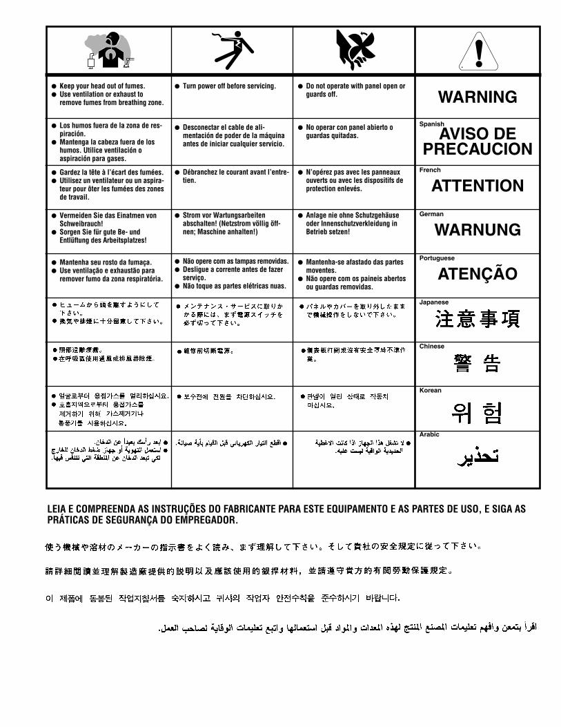
WARNING
AVISO DEPRECAUCION
ATTENTION
WARNUNG
ATENÇÃO
Spanish
French
German
Portuguese
Japanese
Chinese
Korean
Arabic
LEIA E COMPREENDA AS INSTRUÇÕES DO FABRICANTE PARA ESTE EQUIPAMENTO E AS PARTES DE USO, E SIGA ASPRÁTICAS DE SEGURANÇA DO EMPREGADOR.
● Keep your head out of fumes.● Use ventilation or exhaust to
remove fumes from breathing zone.
● Los humos fuera de la zona de res-piración.
● Mantenga la cabeza fuera de loshumos. Utilice ventilación oaspiración para gases.
● Gardez la tête à l’écart des fumées.● Utilisez un ventilateur ou un aspira-
teur pour ôter les fumées des zonesde travail.
● Vermeiden Sie das Einatmen vonSchweibrauch!
● Sorgen Sie für gute Be- undEntlüftung des Arbeitsplatzes!
● Mantenha seu rosto da fumaça.● Use ventilação e exhaustão para
remover fumo da zona respiratória.
● Turn power off before servicing.
● Desconectar el cable de ali-mentación de poder de la máquinaantes de iniciar cualquier servicio.
● Débranchez le courant avant l’entre-tien.
● Strom vor Wartungsarbeitenabschalten! (Netzstrom völlig öff-nen; Maschine anhalten!)
● Não opere com as tampas removidas.● Desligue a corrente antes de fazer
serviço.● Não toque as partes elétricas nuas.
● Do not operate with panel open orguards off.
● No operar con panel abierto oguardas quitadas.
● N’opérez pas avec les panneauxouverts ou avec les dispositifs deprotection enlevés.
● Anlage nie ohne Schutzgehäuseoder Innenschutzverkleidung inBetrieb setzen!
● Mantenha-se afastado das partesmoventes.
● Não opere com os paineis abertosou guardas removidas.

• Sales and Service through Subsidiaries and Distributors Worldwide •
Cleveland, Ohio 44117-1199 U.S.A. TEL: 216.481.8100 FAX: 216.486.1751 WEB SITE: www.lincolnelectric.com
• World's Leader in Welding and Cutting Products •