Embed Size (px)
Citation preview
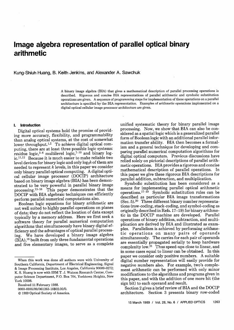
Image algebra representation of parallel optical binaryarithmetic
Kung-Shiuh Huang, B. Keith Jenkins, and Alexander A. Sawchuk
A binary image algebra (BIA) that gives a mathematical description of parallel processing operations is
described. Rigorous and concise BIA representations of parallel arithmetic and symbolic substitutionoperations are given. A sequence of programming steps for implementation of these operations on a parallel
architecture is specified by the BIA representation. Examples of arithmetic operations implemented on a
digital optical cellular image processor architecture are given.
1. Introduction
Digital optical systems hold the promise of provid-ing more accuracy, flexibility, and programmabilitythan analog optical systems, at the cost of somewhatlower throughput.1 2 To achieve digital optical com-puting, there are at least three possible logic systems:residue logic,3-6 multilevel logic,7-10 and binary log-ic.11' 12 Because it is much easier to make reliable twolevel devices for binary logic and only log2k of them areneeded to represent k levels, in this paper we consideronly binary parallel optical computing. A digital opti-cal cellular image processor (DOCIP) architecturebased on binary image algebra (BIA) has been demon-strated to be very powerful in parallel binary imageprocessing.13-16 This paper demonstrates that theDOCIP with BIA algebraic techniques can efficientlyperform parallel numerical computations also.
Boolean logic equations for binary arithmetic arenot well suited to highly parallel operations on planesof data; they do not reflect the location of data excepttypically by a memory address. Here we first seek asoftware theory for parallel numerical computationalgorithms that simultaneously have binary digital ef-ficiency and the advantages of optical parallel process-ing. We have developed a binary image algebra(BIA),6 built from only three fundamental operationsand five elementary images, to serve as a complete
When this work was done all authors were with University ofSouthern California, Department of Electrical Engineering, Signal& Image Processing Institute, Los Angeles, California 90089-0272;K. S. Huang is now with IBM T. J. Watson Research Center, Com-puter Science Department, P.O. Box 704, Yorktown Heights, NewYork 10598.
Received 11 February 1988.0003-6935/89/061263-16$02.00/0.© 1989 Optical Society of America.
unified systematic theory for binary parallel imageprocessing. Now, we show that BIA can also be con-sidered as a spatial logic which is a generalized parallelform of Boolean logic with an additional parallel infor-mation transfer ability. BIA then becomes a formal-ism and a general technique for developing and com-paring parallel numerical computation algorithms fordigital optical computers. Previous discussions haverelied solely on pictorial descriptions of parallel arith-metic operations. BIA provides a rigorous and concisemathematical description of parallel operations. Inthis paper we give these rigorous BIA descriptions forparallel addition, subtraction, and multiplication.
Symbolic substitution has been considered as ameans for implementing parallel optical arithmeticoperations. 17 -19 Symbolic substitution rules can bedescribed as particular BIA image transformations(Sec. 5).20 Three different binary number representa-tions (row-coding, stack-coding, and symbol-coding asoriginally described in Refs. 17-19) for binary arithme-tic in the DOCIP machine are developed. Paralleloperations of binary addition, subtraction, and multi-plication are derived by BIA and illustrated as exam-ples. Parallelism is achieved by performing arithme-tic operations on many pairs of operandssimultaneously. The carries for each pair of operandsare essentially propagated serially to keep hardwarecomplexity low.21 Thus speed-ups close to linear, andin some cases equal to linear can be obtained. In thispaper we consider only positive numbers. A suitabledigital number representation will easily provide fornegative numbers also. For example, two's comple-ment arithmetic can be performed with only minormodifications to the algorithms and programs given inthis paper, and with the addition of one more bit (thesign bit) to each operand and result.
Section 2 gives a brief review of BIA and the DOCIParchitecture. Section 3 presents binary row-coded
15 March 1989 / Vol. 28, No. 6 / APPLIED OPTICS 1263

arithmetic: binary addition and binary multiplication(including a matrix-constant multiplication and anelement-element multiplication). Section 4 presentsbinary stack-coded arithmetic. Section 5 gives a BIArepresentation of symbolic substitution and discussesbinary symbol-coded arithmetic. Section 6 gives acomparison for the above different number represen-tations. Binary subtraction is presented in the Ap-pendices for clarity.
2. Binary Image Algebra (BIA) and DOCIP Architecture
2.1 Review of Binary Image Algebra
Binary image algebra (BIA), extending from mathe-matical morphology,2 2 is a synthesis of Boolean logic,set theory, and image processing. We give here a verybrief summary of BIA. Details are contained in Ref.16.
A binary digital image is usually defined as a func-tion f mapping a spatially sampled set of grid points(x,y) of an orthogonal coordinate system onto the setcomposed of two elements: 1 and 0. However, it will
0 0 00 00 0 1 1 1 1 00 0 0 1 1 1 00 0 0 0 1 1 0000001 00 0 0 0 0 0 00 0 0 0 0 0 0TestedImage X
0 01 1 1000 0 1 1 1 000 0 1 1 1 000 0 1 0 0
0000000Reference R
Image
1 1 1 1 1 1 1 00 000 0 0 0 1 1 1 1 1 11 1 00 0 0 1 00 1 1 1 1 0 0 1 1 1 1 1 11 1 0001 0 0 1 1 1 1 0 0 1 1 1 1 1 1
1 1 1 0 0 1 00 1 1 1 1 0 0 1 1 1 1 11 1 1 1 0 1 00 1 1 1 1 0 0 00 1 1 1 11 1 1 1 1 1 1 000 0000 0 0 00 1 1 11 1 11111 00 0 0 0 0 0 I 00 0 0 0 0 Complement X Union X u R Dilation Xe R
Fig. 1. Example of fundamental operations: complement -,union u, and dilation a.
X = (xy)I(x,y) e W A (X,y) ¢ XI.
(b) Union of two images X and R:
X u R = (xy)j(xy) F X (xy) R.
(c) Dilation of two images X and R:
(2)
(3)
X R {(xl + X2,y1 + Y2) e W(x 1 ,y) E X,(X 2,Y2) e RI (X #- 0) A (R #d 0), (4)10 otherwise.
be more convenient for our image algebra to use onlythe set of coordinates of pixels that have value 1 tospecify an image. In BIA, an image is then treated as aset of coordinates of pixels that have value 1. Thispaper deals with only binary arithmetic; hence, a pixelrepresents a binary bit and an image is a finite 2-D bitplane. We list here only those basic definitions andoperations which will be referred to later.
Definition of Binary Image Algebra (BIA)Binary image algebra is an algebra with an image
space S and a family F of five elementary images andthree fundamental operations. Symbolically,
BIA = [P(W);e,u,-,I,A,A-',B,B- 1], (1)
where S = P(W) andF= ((,u,-,I,A,A- 1 ,B,B-1). Theimage space S, the family F, and all other symbols aredefined in the following.
(1) The Universal Image (the bit plane containingall bits with value 1): The universal image is a set W =I(x,y)Ix E ZnY Zn1, where Zn = 0,± 1,±2,. .. ,±nl andn is a positive integer.
(2) Image Space (the set of all possible bit planes):The image space is the power set (the set of all subsets)of the universal image, i.e., S = P(W).
(3) Image (bit plane): A set X is an image if andonly if X is an element of the image space S, i.e., X is asubimage of the universal image W.
(4) Image Point (a bit with value 1): A sampledpoint (bit) (x,y) is an image point of an image X if andonly if (x,y) is an element of the set X.
(5) Image Transformation (a mapping between bitplanes): An image transformation T is a functionmapping the image space S into the image space S.
(6) Three Fundamental Operations (Fig. 1):(a) Complement of an image X:
Remark: denotes belongs to, A denotes and, v de-notes or, and 0 is the null image having no image point.Note that X usually represents an input image and R isa reference image containing predefined information.We can define other image operations as fundamentaloperations instead of these three operations. The rea-son for choosing these three operations is because oftheir simplicity, simple software design and simplehardware implementation. Dilation can be interpret-ed as a parallel mathematical formalism of the patternsubstitution step in symbolic substitution (Sec. 5).
(7) Five Elementary Images: There are five ele-mentary images:
(a) I 1(0,0)1-consisting of an image point at theorigin,
(b) A = 1(1,0)-consisting of an image point right ofthe origin,
(c) A-' = 1(-1,0)1-consisting of an image point leftof the origin,
(d) B = (0,1)1-consisting of an image point abovethe origin,
(e) B- = (0,-1)}-consisting of an image pointbelow the origin.
In fact, these five elementary images could be reducedto four elementary images, because I = A A-' = B DB-. Any (reference) image can be represented as
X= U ABJ,(ij)eX
where AiBi Ai E B,
A'- A a)A( .. 6 A = (i,0)} if i > 0,
Ai= E A' . A- ' = (i,O)} if i < 0,-i
(5)
1264 APPLIED OPTICS / Vol. 28, No. 6 / 15 March 1989

AO - A ED A-' = I.
(8) Reflected Image: Given an image R, its reflect-ed image is defined as
R = {(-x,-y)(x,y) e RI. (6)
(9) Some Standard Derived Operations:
(a) Difference of X by R [Fig. 2(a)]:
X/R = (xy)I(x,y), X A (x,y) R = X n = X u R. (7)
Remark: X = W/X where W is the universal image.
(b) Intersection of two images X and R [Fig. 2(b)]:
X R. XIR
(a)
n
(8)X n R = (x,y)I(xy) e X A (xy) e RI = X u R.
Remark: X u R = X R.
(c) Erosion of an image X by a reference image R[Fig. 2(c)]:
XeR= XR, (9)where A is defined above. Remark: X R = X e R.The erosion of an image X by a reference image R canbe thought as the complement of the dilation of thebackground by the reflection of the reference image R.In general, the erosion of a non-null image X by a non-null reference image R decreases the size of regions,increases the size of holes, eliminates regions, andbreaks bridges in X.
(d) Symmetric difference of two images [Fig. 2(d)]:
XAR = (X/R) u (RIX) = X u R u R u X. (10)
Remark: The symmetric difference is a commutativeoperation, and is its own inverse.
(e) Hit or miss transform ( of an image X by animage pair R = (R1,R2) [Fig. 2(e)]:
XGR=(Xe R1)n,(Xe R2)=(Xa@ R1)u(XaR 2). (11)
Remark: The hit or miss transform of an image X by areference image pair R = (R1 ,R2) formally describes thepattern recognition step in symbolic substitution (Sec.5); and it is used to match the shape (or template)defined by the reference image pair R where R, definesthe foreground of the shape and R2 defines the back-ground of the shape. The conditions are that theforeground X must match R1 (i.e., X E3 R,), whilesimultaneously the background X matches R2 (i.e.,X e R2). Note the similarity of the symmetric differ-ence (parallel bitwise comparison) and the hit or misstransform (parallel shape or symbol recognition).
The important results of BIA are: (1) any imagetransformation can be implemented by the three fun-damental operations with appropriate reference im-ages; (2) any reference image can be generated from theelementary images by using the three fundamentaloperations; and (3) BIA provides an efficient represen-tation for many parallel image processing algorithms(e.g., shape and size verifications 16 ). Here we demon-strate that BIA is also a fundamental tool for parallelnumerical computation.
X XnR
(b)
e
x
x
XeR(C)
R X AR
(d)
f: foreground poinswtvau b: background points with value 0
[ (],= ( E
R=(R,, R2)
R2
R=(R,, R2 )
Image X (e) xOR
Fig. 2. Some standard derived image operations. The shadedregions in (1)-(d) correspond to pixels with value 1: (a) difference;(b) intersection; (c) erosion; (d) symmetric difference; (e) hit or miss
transform (template matching).
2.2. Review of DOCIP Architecture
We have designed a class of the digital optical cellu-lar image processors (DOCIPs) for effectively imple-menting BIA.13-15 Here we only summarize their ma-jor characteristics. Details are given in Refs. 14 and15. To map BIA into the DOCIP architecture in atransparent way, we first define the DOCIP algebra-ically:
15 March 1989 / Vol. 28, No. 6 / APPLIED OPTICS 1265

Definition of Cellular AutomataA cellular automaton is an algebra A = (S;F,N,)
where S is the state space which is a set of states, F is afamily of transition functions, and N, is the neighbor-hood configuration.
Constraints on a cellular automaton for Implement-ing BIA:
(1)SjP(W),
(2) F D 19,U,-},
(3) N, D I u A u A u B u orN A u u B u Bt',
where v means contains.Thus, in terms of cellular automata, the DOCIPs
have to satisfy the above constraints for realizing BIA.For storing input images and temporary results in amore flexible way, the DOCIPs utilize three memorymodules and all share the same algebraic structure(except the neighborhood configuration):
== Image Data NxN Matrix)-. Control Signal
- ComplementU Union(D Diation
Control Unit
Imag In
Imageor Data Out
Fig. 3. Digital optical cellular image processor (DOCIP) architec-ture-one implementation of binary image Algebra (BIA). TheDOCIP-array requires 9 (or 5) control bits for reference image Ej.The DOCIP-hypercube requires O(logN) control bits for reference
image Ei.
DOCIP = [P(W X W X W);0,u,-,N, (12)
where X denotes cross product and N, can be one of thefollowing four types:
(1) DOCIP-array4: each cell connects with its fournearest neighbors and itself, i.e.,
Narray4 = I u A u A u B u B-1. (13)
(2) DOCIP-array8: each cell connects with its eightnearest neighbors and itself, i.e.,
Narray8 = U A'Bi. (i4)ij=-t
(3) DOCIP-hypercube4: each cell connects withthose cells in the 4 directions at distances 1,2,4,8,...,2kfrom itself, i.e.,
Nhypercube4 U (A' u B, (15)i=0,11, 2,.. 2
where k is sufficiently large for the connections totraverse the entire array of cells.
(4) DOCIP-hypercube8: each cell connects withthose cells in the 8 directions at distances 1,2,4,8,...,2hfrom itself, i.e.,
Nhypercube8 = U (Ai u B u AB u AB-). (16)i=0,±l,±2,.,±2k
From the above algebraic description, the DOCIPshave the same algebraic structure and differ only intheir neighborhood configurations N Thus, theyshare the same architecture shown in Fig. 3, but havedifferent configurations of the reference images Ei de-pending on the optical interconnection network whichdefines the neighborhood. In practical applications, alarger reference image R can be generated from a set ofsmaller reference image(s) Ei by a sequential dilation.If it is possible to decompose R into a sequence R = E(D3 E2 (33 . .. E then
X R = I ... [(X El) Ee] ... Ehl. (17)
This decomposition may not exist, in which case R canalways be decomposed as R = R u R2 u . . . u R, andthen
XeR = (XDR 1 ) u (X R2 )u ... u(XRk), (18)
where each Rj can be decomposed into smaller refer-ence images Ej.14
,23
Basically, the proposed DOCIP shown in Fig. 3 is acellular SIMD machine and consists of an array of cellsor processing elements (PEs) under the supervision ofa control unit. The control unit includes a clock, aprogram counter, a test and branch module for feed-back control, and an instruction decoder for storinginstructions and decoding them to supervise cells.The array of cells includes a 1 X 3 line destinationselector, where each line is N 2 bits wide, three N X N X1 bit memories for storing images, a memory selector,and a dilation unit. It operates as follows: (1) abinary image (N X N matrix) is input into the destina-tion selector and then stored in any memory (or set ofmemories) as the instruction specifies; (2) after one tothree images have been stored, these images and theircomplements are piped into the next stage, whichforms the union of any combination of images (speci-fied by the instruction); (3) the result is sent to adilation unit where the reference image specified bythe instruction is used to control the type of dilation;(4) finally, the dilated image can be output, tested forprogram control, or fed back to step (1) as the instruc-tion specifies.
The DOCIP machine (Fig. 3) has one instruction; itimplements the three fundamental operations of BIAalong with fetch and store.23 This design uses theparallelism of optics to simultaneously execute in-structions involving all N2 picture elements. Eachinstruction takes one complete cycle to execute. Notethat the DOCIP machine can perform a dilation by anyreference image R that is a subset of the neighborhoodconfiguration, N,, in a single clock cycle.
The entire system can be realized by an optical gatearray with optical 3-D interconnections.11 1 2 24 Figure4 describes an optical implementation concept for theDOCIP architecture. The DOCIP has very low cellhardware complexity to maximize parallelism, yetenough cell sophistication to permit the machine to
1266 APPLIED OPTICS / Vol. 28, No. 6 / 15 March 1989

k-bit-14__, N-bitlen-t length -
I.'.
rNv | * | N1/k
R
Fig. 5. Binary row-coded numbers.V " Noutput v
intra-PE=/ one PE and inter-PE
(optical gate array) interconnection unit (optical gate array)(optical hologram )
Fig. 4. DOCIP physical concept. Each processing element (PE) orcell connects with its cellular array or cellular hypercube neighborsand itself by optical 3-D interconnections. The optical hologramprovides both intracell and intercell interconnections. Intracellinterconnections and imaging optics are omtted for clarity. Theinput and output sides of the optical gate array are interconnectedby an optical feedback path and are shown separately for clarity.
execute useful programs. The use of optical intercon-nections permits a cellular hypercube topology to beimplemented without paying a large penalty in chiparea (the cellular hypercube interconnections arespace invariant which implies relatively low hologramcomplexity); it also enables images to be input to andoutput from the machine in parallel.
3. Binary Row-Coded Arithmetic
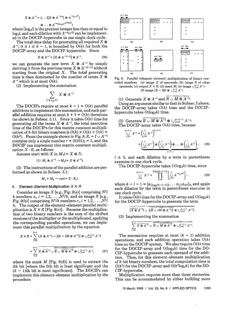
Binary addition of two k-bit numbers yields at mostk + 1 bits, and binary multiplication of two k-bitnumbers yields at most 2k bits. In this paper, weassume that all input numbers are padded with enoughzeros to avoid the possibility of overflow. This alsoguarantees that the different operands in the imagewill be treated separately. A binary row-coded num-ber is encoded in a part of a row of an image. Althoughthe word lengths of numbers do not need to be equal,we assume in this discussion that an image (bit plane)with N X N bits contains N2/k numbers of h-bit lengthas a simple illustration (Fig. 5). In this section, wedescribe parallel addition and multiplication by BIAexpressions and their programs on the DOCIP ma-chine. Subtraction is discussed in Appendix A.
3.1. Addition of Binary Row-Coded Numbers
Consider an image X [e.g., Fig. 6(a)] composed of N2 /k numbers xi, i = 1,2, .. ,N2 /k, an image R [e.g., Fig.6(b)] composed of N2 /k numbers ri, i = 1,2,...,N2/k,and the output of the addition S = X + R [Fig. 6(c)].To realize this addition in parallel by means of BIA, wefirst consider the serial (carry-propagate) addition of 2binary numbers si = xi + ri. The first step of serialaddition is to add the least significant bits, say xi(o) andri(o). The Boolean logic equations for adding the twoleast significant bits (half-adder) are
sum bit: Si(0) = i(o) XOR ri(O
MSB LSE
(a) (b) (c)
Fig. 6. Parallel addition of binary row-coded numbers (I): (a)image X of operands; (b) image R of other operands; (c) output
X + R.
carry bit: ci(0) = Xi(e) AND ri(e).
Now, applying the corresponding parallel operationsof XOR and AND, i.e., the symmetrical difference A andintersection n, and shifting the set of carry bits by adilation ED, we can implement parallel addition by thefollowing recursive equations:
(1) Define the initial states of images of sum bitsand carry bits (called sum-bit image and carry-bitimage) at time to as
S(t,) = X, C(to) = R. (19)
(2) The recursive relation between the states of thesum-bit image and carry-bit image at two adjacenttime intervals is then
S(tijl) = S(ti) A C(ti) = S(ti) U C(ti) u S(ti) u C(ti), (20)
C(tijl) = [S(ti) n C(ti)] E A-' = S(ti) u C(t1) @ A', (21)
where i = 0,1,2, .. ,k + 1, and the elementary imageA-' is used to shift the carry-bit image one bit to theleft for the next iteration.
(3) After a maximum of k + 1 iterations, the sum-bitimage is the result and the carry-bit image is the nullimage 0:
S(tk+l) = X + R, C(tk+l) = 0. (22)
This procedure is illustrated in Fig. 7. The result ofparallel addition of binary numbers with a maximumk-bit word size is obtained after k + 1 iterations. Thisalgorithm can be implemented in the DOCIP architec-ture by the program (instructions) given below. Ml,M2, and M3 represent the three N X N-bit memories.X - Ml denotes store X into memory Ml. Eachnumbered line represents a single DOCIP machine
15 March 1989 / Vol. 28, No. 6 / APPLIED OPTICS 1267
k-bitIn N-bitlength - t
N-bitlength 1
X
length-bit
1

instruction for one value of i. Comments are in brack-ets.
Assume start with X in Mj[=S(to)] and R inM2 [= C(t0)]-
First to kth iterations:
(1) M u Al - M3[= S(ti) u C(ti)I,
(2) MI u M2 - Ml I= S(ti) Q01]
(3) Ml u M2 u M3 - M2[= S(ti) u C(tj)],
(4) V u M~2 - Ml[= S(ti+,)],
(5) V3 (D A-'l M,[= C(ti+,)],
where i = 0,1,2,. .. ,k - 1.(k + 1)th iteration:
(1) MI U MI - M3[= S(tk) C(tk)1,
(2) Ml U M2 -Ml[= S(tk) U C(tk)I,
(3) MA u M3 - out[= S(tk+l) = X + R].
The total number of clock cycles for the execution ofthis program on the DOCIP machine is t(k) < 5k + 3 =0(k), which is independent of the number of wordsbeing added.
In fact, BIA can be used to devise a parallel form of aconditional-sum adder or carry-lookahead adder forfurther extracting additional parallelism, and the exe-cution time of this addition can be reduced to O(log2k).Obviously, a trade-off exists between execution timeand hardware complexity. This paper concentratesonly on some simple algorithms.
3.2. Multiplication of Binary Row-Coded Numbers
Using the representation illustrated in Fig. 5, wedefine a parallel (matrix-constant) multiplication ofan image set of binary numbers and one single binarynumber X Rr, and parallel (element-element) multi-plication of two image sets of binary numbers X X R.
I. Matrix-Constant Multiplication X. R,
Consider an image X [e.g., Fig. 8(a)] comprising N2/k numbers xi, i = 1,2, .. N2/k, and a reference imageRr [e.g., Fig. 8(b)] comprising only one single k-bitbinary number r = [r(k-)r(k-2) ... r(o)]2. The output ofthe parallel multiplication is X Rr [Fig. 8(c)]. Torealize it, we first consider the serial multiplication oftwo binary numbers that is the sum of the shiftedversions of the multiplier or the multiplicand. Then,by applying the corresponding parallel operations andparallel shifting by a dilation @, we can implement thisparallel multiplication by the equation
(23)X-R,= E XA-',1,Vr() = I
where the sum notation _ refers to a sequence ofparallel additions and the parallel addition + is de-fined in Subsec. 3.1.
The DOCIP takes 0(k 2) clock cycles for implement-ing this matrix-constant multiplication. Its proce-dure involves:
S(t,) =
S(t2 ) = C(t2) =
C(t3) =S(t6) =
q(Zte - (Y0e) =
_- - - -- 9\S- ,
Fig. 7. Parallel addition of binary row-coded numbers (II): Theprocedure for parallel addition X + R where X and R are shown in
Fig. 6, S(t5) = S = X + R and C(t5) = .
k=7 bits
(a1 (b) (Cl
Fig. 8. Parallel (matrix-constant) multiplication of binary row-coded numbers: (a) image X of operands; (b) image R containing
only a single number; (c) output X * Rr.
(1) Generating the term X A-1:The DOCIP-array requires at most I < k - 1 = O(k)
clock cycles, because
A- = (A-')'
(24)
The DOCIP-hypercube requires at most log21 <
log2(k - 1) = 0(log 2k) clock cycles, because we canrewrite as a binary number = [a(LIog21J) . . . a(l)a(o)]2,and we have
[tog2 1J
A-' = A-( 2j=o
Aa() A-a(l),21 3... A-a(L920 ,2bog2dI (25)
1268 APPLIED OPTICS / Vol. 28, No. 6 / 15 March 1989
=_A-'a�A-'a) a)A-1,I
X A-= ( { [X A-(0)] A-a(l)l]
(D a Aa(Log21)a 2 Log2 lJ)
where [log21 is the greatest integer less than or equal tolog21, and each dilation with A-a0w-2 can be implement-ed in the DOCIP-hypercube in one single clock cycle.
The total time delay for generating all required X DA-l, 0 • I < k - 1, is bounded by 0(k) for both theDOCIP-array and the DOCIP-hypercube. Since
X A- = [X e A-('-)] A-', (26)
we can generate the new term X A- 1 by simplyderiving it from the previous term X ED A-('-1) withoutstarting from the original X. The total generatingtime is then dominated by the number of terms X DA-' which is at most O(k).
(2) Implementing the summation
Z X@A-'lVr(t)-1
The DOCIPs require at most k - 1 = 0(k) paralleladditions to implement this summation, and each par-allel addition requires at most k + 1 = O(k) iterations(as shown in Subsec. 3.1). Since it takes O(k) time forgenerating all the terms X $1 A-, the total executiontime of the DOCIPs for this matrix-constant multipli-cation of k-bit binary numbers is 0(k) X 0(k) + 0(k) =O(k2 ). From the example shown in Fig. 8, Rr = I u A-2
contains only a single number r = (0101)2 = 5, and theDOCIP can implement this matrix-constant multipli-cation X Rr as follows:
Assume start with X in M1 (= X @ I).
(1) M, s A-2 M2(= X A-2).
(2) The instructions of the parallel addition are per-formed as shown in Subsec. 3.1:
Ml + M2 - out(= X Rr)
II. Element-Element Multiplication X X R
Consider an image X [e.g., Fig. 9(a)] comprising N2/k numbers xi, i = 1,2, .. ,N2 /k, and an image R [e.g.,Fig. 9(b)] comprising N2 /k numbers ri, i = 1,2,. .. N2/k. The output of the element-element parallel multi-plication is X X R [Fig. 9(c)]. Because the multiplica-tion of two binary numbers is the sum of the shiftedversions of the multiplier or the multiplicand, applyingthe corresponding parallel operations, we can imple-ment this parallel multiplication by the equation
k-1X X R = (X a) A-') n [R r, (M @) A-')] E Uhj-1- A-'j
1=0
k-1= eX@A=' u A u M sA-' A Uj0-1A-j, (27)
1=0
where the mask M [Fig. 9(d)] is used to extract theIth bit [where the 0th bit is least significant and the(k - 1)th bit is most significant]. The DOCIPs canimplement this element-element multiplication by theprocedure
Ca) (b) (C)
=7 bits k=7 bits
00.. .0 00 0 000
Oo,., 1tl k=7 bits
(d) i (ft)
Fig. 9. Parallel (element-element) multiplication of binary row-coded numbers: (a) image X of operands; (b) image R of other
operands; (c) output X X R; (d) mask M; (e) image u-j1 A-j;(f) image (R n M) 63 uk- 1 Aj.
(1) Generate X a) A-' and R u M @3 AF:Using an argument similar to that in Subsec. I above,
the DOCIP-array takes 0(k) time and the DOCIP-hypercube takes 0(log 2k) time.
(2) Generate R u M E A' $ Uj= A :The DOCIP-array takes 0(k) time, because
k-l-i 1A -
UA- U Ajj=0 =
(U A-j) 03( A-) CD . .. ED t A-)j=0 /\i=kI0I
(28)
1 > 0, and each dilation by a term in parenthesesexecutes in one clock cycle.
The DOCIP-hypercube takes 0(log 2k) time, sincek-l-l Ltog2(h-1-i)j Fn jl
U A- = fI [U Aj=0 n=0 j=0 (29)
where k - I - = [aLlog2 (k-1-1)j) ... a(l)a(o)]2, and againeach dilation by the term in parentheses executes inone clock cycle.
It takes 0(k) time for the DOCIP-array and 0(log 2k)for the DOCIP-hypercube to generate the term
(X @ A-') u 1[9 u (M e A-')] @ U I A-3 j.
(3) Implementing the summationk-1
X CDet u R u M @ A-' jUk0 A-'.1=0
The summation requires at most (k - 1) additionoperations, and each addition operation takes 0(k)time on the DOCIP system. We also require O(k) timefor the DOCIP-array and 0(log 2k) time for the DO-CIP-hypercube to generate each operand of the addi-tion. Thus, for this element-element multiplicationof k-bit binary numbers, the total computation time is0(k 3) for the DOCIP-array and 0(k210g2k) for the DO-CIP-hypercube.
Multiplication requires more than three memories.This can be accommodated by either building more
15 March 1989 / Vol. 28, No. 6 / APPLIED OPTICS 1269
k,7 -. t
memory into the DOCIP machine or by swapping in-termediate results into and out of an external memory.In the latter case we assume the external memory canbe loaded and unloaded with one image in a single timestep. In Sec. 4, binary stack-coded arithmetic alsorequires more than three memories; we make the sameassumptions on the use of an external memory.
For binary column-coded arithmetic, a number isencoded in a part of a column of an image as in Fig. 10.All the algorithms derived in this section can also beapplied to binary column-coded numbers except thatwe replace the elementary image A-' by a differentelementary image B for shifting the carry-bit image orborrow-bit image in the vertical direction.
k-bit length k
N -bitlength
I
N-bitI4 - length -
.. x
;.- Most significant bit
I- Least significant bit
- ZN2/k
Fig. 10. Binary column-coded numbers.
4. Binary Stack-Coded Arithmetic
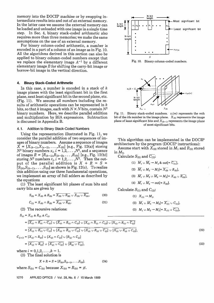
In this case, a number is encoded in a stack of kimage planes with the least significant bit in the firstplane, next least significant bit in the second plane, etc.(Fig. 11). We assume all numbers including the re-sults of arithmetic operations can be represented in kbits, so that k images, each with N x N bits, contain N2
binary numbers. Here, we describe parallel additionand multiplication by BIA expressions. Subtractionis discussed in Appendix B.
4.1. Addition to Binary Stack-Coded Numbers
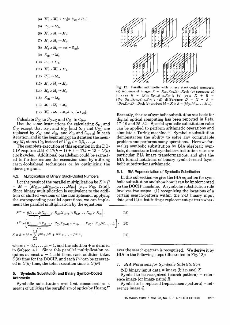
Using the representation illustrated in Fig. 11, weconsider the parallel addition of two sequences of im-ages of binary numbers. Assume a sequence of imagesX = [X(k-l),X(x- 2 ),... ,X(0)] [e.g., Fig. 12(a)] storingN2 binary numbers xi, i = 1,2,.. . N2, and a sequenceof images R = [R(k-l),R(k-2) . . ,R(o)] [e.g., Fig. 12(b)]storing N2 numbers r, i = 1,2, . .. ,N2. Then the out-put of the parallel addition is X + R = S =[S(k),S(k-1), ... ,S(o)] as shown in Fig. 12(c). To realizethis addition using our three fundamental operations,we implement an array of full adders as described bythe equations
(1) The least significant bit planes of sum bits andcarry bits are given by
S() = X(0 ) A R(0) = X(,) u R(O) u X(0) u R(O),
C(,l = X(,0 n R() = X(O u R(,0 .
(2) The recursive relations:
S(i) = X(i) A R(i),A C(i)
(30)
(31)
x,(k - 1)-
N-bitlength
.ZN2 ( )
x,. I x(O)
Fig. 11. Binary stack-coded numbers. x(m) represents the mthbit of the ith number in the image plane. X(o) represents the imageplane of least significant bits and X(kil represents the image plane
of most significant bits.
This algorithm can be implemented in the DOCIParchitecture by the program (DOCIP instructions):
Assume start with X(o) stored in Ml and R(o) storedin M2 .
Calculate S(o) and C(l):
(1) Ml u M2 - M3 & out[= C(1 1],
(2) M1 u M,- Ml[= X(0 ) u R()1]
(3) Ml U M2 U M3 -M2[= X(0) U B(,0 ],
(4) M, u M2 - out[= S()1].
Calculate S(l) and C(2):
(1) X(l) [ Ml,
(2) Yl U M3 M2[= X(> U C(,,],
(3) M M3 - Ml[= X(l) u C(l) I
= [X(,1 B (i-) n C(Ji u [X(i, r R( C(,1 u [X(,j n R() n C(i,]u [X(,j n R() n C(i]
= Wu () u C(i) U [X() U (i) U C1()] U [X() u R1 1 u C(i] U [X() u R( u C()],
C(il) = [X(i) n R()] u [X(i) C(i)] u [R() n C(i)]
= [X u u [Xi) U C(i] u [Bk,1 u C(i],
where i = 0,1,2,... ,k - 1.(3) The final solution is
X + R = S = [S(h),S(k-l, * * ,S(0)]-
where S(k) = C(k) because X(k) = R(k) = 0.
(34)
1270 APPLIED OPTICS / Vol. 28, No. 6 / 15 March 1989
(32)
(33)
i
(4) Ml1 u M2 - Ml[= X(1 ) A C(1 )],
(5) R(,) M2,
(6) M u M2 -
(7) Ml u M2 -
(8) M2 u A3-
(9) X(,) - Ml,
(10) R(1 M2,
(11) M 1 U M 2 -
(12) Al)u Ml,
(13) Ml u M2 i
IM3,
M2
out[= S(1)],
M3,
M2
(14) M2 u M3 - M3 ,
(15) X - M2,
(16) M u M2- M2,
(17) 2 u M3 - M3 & out[= C(2)1].
Calculate S(2) to S(k-) and C(3) to C(k):Use the same instructions for calculating S(i) and
C(2) except that X(l) and R(,) [and S(i) and C(2)] arereplaced by X(j) and R(j) [and S(i) and C(i+,)] in eachiteration, and in the beginning of an iteration the mem-ory M3 stores C(1) instead of C(l), i = 2,3, . . . ,k.
The complete execution of this operation in the DO-CIP requires t(k) < 17(k - 1) + 4 = 17k - 13 = 0(k)clock cycles. Additional parallelism could be extract-ed to further reduce the execution time by utilizingcarry-lookahead techniques or by optimizing theabove program.
4.2. Multiplication of Binary Stack-Coded Numbers
Let the result of the parallel multiplication be X X R= M = [(2k-lM(2k-2), .. . M(O)] [e.g., Fig. 12(e)].Since binary multiplication is equivalent to the addi-tion of shifted versions of the multiplicand, applyingthe corresponding parallel operations, we can imple-ment the parallel multiplication by the equations
P(°) = [00 0... ,,X_.) n R(o)X(k-2) nBR01 . X1o 1n R(0)]
p1'1 = [,0OX,,) RB(,Xk-2) n R(j)1.,X( 0) n R(),0,0,..*
k-k-l
XXR == P(i) P(O) +P(l) +... +(k),i=0
where i = 0,1,... ,k - 1, and the addition + is definedin Subsec. 4.1. Since this parallel multiplication re-quires at most k - 1 additions, each addition takesO(k) time for the DOCIP, and each p(i) can be generat-ed in 0(k) time, the total execution time is 0(k3)
5. Symbolic Substitutian and Binary Symbol-CodedArithmetic
Symbolic substitution was first considered as ameans of utilizing the parallelism of optics by Huang.17
Fig. 12. Parallel arithmetic with binary stack-coded numbers:(a) sequence of images X = [X(3),X(2),X(l),X(0)]; (b) sequence ofimages R = [R(3),R(2,R(l,R(o,]; (c) sum X + R =[S(4),S(3),S(2),S(l),S(o)]; (d) difference D = X - R =[D(3),D(2,,D(ll,D(o]; (e) product M = X X R = [M(7),M(6),. M(o)l].
Recently, the use of symbolic substitution as a basis fordigital optical computing has been reported in Refs.17-19 and 25-32. Special symbolic substitution rulescan be applied to perform arithmetic operations andsimulate a Turing machine.'9 Symbolic substitutiondemonstrates the ability to solve any computableproblem and performs many operations. Here we for-malize symbolic substitution by BIA algebraic sym-bols, demonstrate that symbolic substitution rules areparticular BIA image transformations, and give theBIA formal notations of binary symbol-coded (sym-bolic substitution) arithmetic.
5.1. BIA Representation of Symbolic Substitution
In this subsection we give the BIA equation for sym-bolic substitution and show how it can be implementedon the DOCIP machine. A symbolic substitution ruleinvolves two steps: (1) recognizing the locations of acertain search-pattern within the 2-D binary inputdata, and (2) substituting a replacement-pattern wher-
(35)
,o,, I (36)
(37)
ever the search-pattern is recognized. We derive it byBIA in the following steps (illustrated in Fig. 13):
1. BIA Notations for Symbolic Substitution2-D binary input data = image (bit plane) X.Symbol to be recognized (search-pattern) = refer-
ence image (or image pairs) R.Symbol to be replaced (replacement-pattern) = ref-
erence image Q.
15 March 1989 / Vol. 28, No. 6 / APPLIED OPTICS 1271

Search-pattern I Replacement-patternR = (R, R2 )t j Q
Foreground - admground -
Patern of l's Puttern f os Foreground recognition
In t ima e L J\ Full recogni'on Substitution output
1 0~r Gd I \e ~ Ilo v o Io I I I T
Background recognition}~~~~11 Ia aO \I 10101101 (0o . o I
Onngin X o X ®R (X ®R) Q
.o o t o \t 3(X®R) n M
XeR 2 =XeR 2 l oI
Symbolic substitution rule -Hit or miss transform + Dilation t i io | I..
M
Fig. 13. BIA representation of symbolic substitution. The option-al mask M is for controlling the block seach region.
2. Symbolic Substitution RuleStep 1, recognition of the search-pattern:(a) Foreground recognizer: the locations of a cer-
tain spatial search-pattern R1 (defined by its fore-ground) within the foreground of the 2-D input data Xcan be recognized by the erosion operation of X and R1:
X e R = X P P. (38)
(b) Background recognizer: the locations of a cer-tain spatial search-pattern R2 within the backgroundof the 2-D input data X can be recognized by theerosion of X and R2:
e R = X ) R2. (39)
(c) Full recognizer: by combining the two abovesteps, the locations of a certain spatial search-patternR = (R,,R2) (RI defines the foreground, and R2 definesthe background) within the 2-D input data X can berecognized by the hit or miss transform of X and R:
X ® R = (X e RI) n (X e R,) = (X a) fl) u (X D R2). (40)
Step 2, substitution of the replacement-pattern:Substituter: a new replacement-pattern Q can be
substituted for R wherever the search-pattern R isrecognized by the dilation of X 0 R by Q.
Synthesis:A complete symbolic substitution rule is implement-
ed by the hit or miss transform of X by R followed bythe dilation by Q:
(X®B R) Q = [(XERI) r (XeB,)] Q
= (X (D PI) (X a) R2) a Q (41)
Optional masking:An optional mask M can be used for controlling the
block search region. A symbolic substitution rule canbe modified as
[(X OR) n M] @ Q. (42)
By proper choice of M, the search can be made inoverlapping, disjoint or noncontiguous blocks.
Symbolic Recognition I Symbolic Substitution (Hit or Miss Transform) (Dilation)
Symbolic Recognition 2 Symbolic Substitution2- (Hit or Mis Translorm) (Dilation)Input .- Union Ou
image OUno Oux U ~~~~~~~~~U
|Symbolic Recognition I Symbolic Substitution p|(Hit or Miss Transform) (Dilation)
Fig.14. Symbolic substitution system with p symbolic substitutionrules.
3. Symbolic Substitution System (Fig. 14)To work with more than one rule (say p substitution
rules) for practical applications, a symbolic substitu-tion processor produces several copies of the input X,provides p different recognizer-substituter units, andthen combines the outputs of various units to form anew output. Thus, a symbolic substitution system isimplemented by
U [X R(')] e Q(i)i=l
(43)
where RW and Q(W),i = 1,2,... ,p, are the referenceimage pairs and replacement patterns in the ith sym-bolic substitution rule. This, then, is the BIA formulafor general symbolic substitution.
Hence, a general mathematical formalism of sym-bolic substitution has been developed. For a localsearch-pattern and replacement-pattern (i.e., R,,R 2,QC Narray or Nhypercube), the DOCIP-array or DOCIP-hypercube can implement a symbolic substitution rulein four (or five with the optional mask) steps:
Assume start with X in MI.
(1) M 1 1 P I-M2,
(2) MA ED f2 -M,
(3) M, u M3 - M3,
(4) M3 @ Q -out[= (X ( R) Q].
Let the pixels used in the substitution rule(s) of asymbolic substitution processor be the neighborhood,N 3 of the processor. We see from the above steps thatthe DOCIP can simulate the symbolic substitutionprocessor in constant time if the two machines have thesame neighborhood. If N3 is not a subset of the DO-CIP neighborhood, the simulation will take longer. Ineither case, it is not presently known how many steps ittakes the symbolic substitution processor to simulatethe DOCIP.
5.2. Binary Symbol-Coded (Symbolic Substitution)Arithmetic
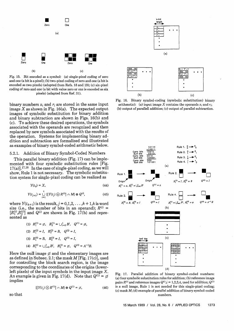
A bit in a binary number is encoded symbolically aspixels of an image (Fig. 15). In this subsection, weprimarily concentrate on single-pixel coding: a logicvalue (0 or 1) is represented by a single pixel (dark orbright) [Fig. 15(a)], as in the binary row and stack-coded number representations, but the operands of
1272 APPLIED OPTICS / Vol. 28, No. 6 / 15 March 1989
* IIZero Ce
(a)
* Li WMEO * fAEZero Ore Zero
(b) (c)
Fig. 15. Bit encoded as a symbol: (a) single-pixel coding of zeroand one (a bit is a pixel); (b) two-pixel coding of zero and one (a bit isencoded as two pixels) (adapted from Refs. 18 and 19); (c) six-pixelcoding of zero and one (a bit with value zero or one is encoded as six
pixels) (adapted from Ref. 31).
binary numbers xi and ri are stored in the same inputimage X as shown in Fig. 16(a). The expected outputimages of symbolic substitution for binary additionand binary subtraction are shown in Figs. 16(b) and(c). To achieve-these desired operations, the symbolsassociated with the operands are recognized and thenreplaced by new symbols associated with the results ofthe operation. Systems for implementing binary ad-dition and subtraction are formalized and illustratedas examples of binary symbol-coded arithmetic below.
5.2.1. Addition of Binary Symbol-Coded NumbersThis parallel binary addition (Fig. 17) can be imple-
mented with four symbolic substitution rules [Fig.17(a)].17 "18 In the case of single-pixel coding, as we willshow, Rule 1 is not necessary. The symbolic substitu-tion system for single-pixel coding can be realized as
Y(to) = X, (44)
000... 00x,+ r, . .000... 00
b+r,
(b)
x,- roo... oo . .x,- r,000...00
(c)
Fig. 16. Binary symbol-coding (symbolic substitution) binaryarithmetic): (a) input image X contains the operands xi and ri;
(b) output of parallell addition; (c) output of parallel subtraction.
Carry bitsSum bits
Carry bitsSum bitsCarry bitsSum bits
Rule 1
A' Origin
R('') = , R2) = U!l~ B
10110+1001110010
010o100101000010001 01001
U
OriginX
QMl =
Rule 1.
Rule 2.
Rule 3.
Rule 4.
° _ 0n
,°-° 01
.0 0
11 10
(a)
Rule 2. *
h(2 = I, 42) =
=
Q L2)=I
4Y(tj+,) = U [Y(tj) )R(')] n MA @ Q('), (45)
where Y(tk+l) is the result, j= 0,1,2,. , + 1,k is wordsize (i.e., the number of bits in an operand); RW =[R(i),R(i)] and Q(i) are shown in Fig. 17(b) and repre-sented as
(1) R( 1) = 0, R(1 ) = UJ=0 Bi, QM11 =
(2) R(2) = I, R(2) = B, Q(2) - I
(3) RB13) = B, R(3)= I, Q(3) = I
(4) Bj1 = UI = (4) = 0 , Q(4) = A-B.
Here the null image 0 and the elementary images areas defined in Subsec. 2.1; the mask M [Fig. 17(c)], usedfor controlling the block search region, is the imagecorresponding to the coordinates of the origins (lower-left pixels) of the input symbols in the input image X.An example is given in Fig. 17(d). Note that Q(l) = 0implies
I[Y(tj) O R"1 )] n M} a Q111= 0, (46)
so that
Rule 3. 1 N
R(3)=B, 4R)=I QM3 = I
k-5 bits
Rule 4. 0 ,
iR(
4U'-u 4
4=
(b)
= B
U()=Al
(c)
1 OOO
OSQ~~~~~~~~~~~~~~~~~
(d)
Fig. 17. Parallel addition of binary symbol-coded numbers:(a) four symbolic substitution rules for addition; (b) reference imagepairs RBi' and reference images Q(ilJ = 1,2,3,4, used for addition; Q(1)is a null image, Rule 1 is not needed for this single-pixel coding;(c) mask M; (d) example of parallel addition of binary symbol-coded
numbers.
15 March 1989 / Vol. 28, No. 6 / APPLIED OPTICS 1273
k-bitlength
DO.E* .One
(a)
ERule 1. L
Origin
E
origin%
Li ERule 3 H I L
L E
HRule 2. i
LiH
ULi
H
Rule 4 ! . *
L U
(a)
Rule 1. D H .D E H Rule 2- E° _ LiE0H U EH U 'D E E D E E
)Elmo * i[tr- Mr- *°Rule 3 D E D Rule 4. E J iE" E i'EMFJ FeDEE MDMOD - ED *D0 DEE
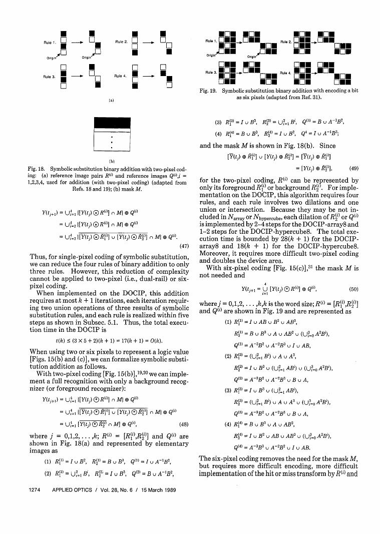
Fig. 19. Symbolic substitution binary addition with encoding a bitas six pixels (adapted from Ref. 31).
(b)
Fig. 18. Symbolic substitution binary addition with two-pixel cod-ing: (a) reference image pairs R" and reference images Q),i =1,2,3,4, used for addition (with two-pixel coding) (adapted from
Refs. 18 and 19); (b) mask M.
Y(tj+,) = U4=I [Y(tj) El) B"1] R M} @ Q(i
- U4=2 ][Y(tj) B R()] l MI @ Q(i)
=-2 ,[ Y(tj) ®j(Mi1] U [Y(t,) G(il,"] n Ma) e ).(47)
Thus, for single-pixel coding of symbolic substitution,we can reduce the four rules of binary addition to onlythree rules. However, this reduction of complexitycannot be applied to two-pixel (i.e., dual-rail) or six-pixel coding.
When implemented on the DOCIP, this additionrequires at most k + 1 iterations, each iteration requir-ing two union operations of three results of symbolicsubstitution rules, and each rule is realized within fivesteps as shown in Subsec. 5.1. Thus, the total execu-tion time in the DOCIP is
t(k) S (3 x 5 + 2)(k + 1) = 17(k + 1) = 0(k).
When using two or six pixels to represent a logic value[Figs. 15(b) and (c)], we can formalize symbolic substi-tution addition as follows.
With two-pixel coding [Fig. 15(b)] ,19,20 we can imple-ment a full recognition with only a background recog-nizer (or foreground recognizer):
Y(tj+,) = UI=, [Y(tj) E R(i)] ni M Ef Q(i)
= =, [Y(t)® I MO 1 u [Y(tj) ( R2 M([ Q
=I Y(tj) O5 R2') fi M, (E Q(i), (48)
where 0,1,2, ... ,k; R 1= [R(¶),R(')] and Q are
shown in Fig. 18(a) and represented by elementaryimages as
(1) R( = I u B, R = B u B, Q(1) = I U A-1B 2 ,
(2 l) = U= Bi (21 = 3, Q(2) =BU-12,
(3) R(3) = I u B3, R3) = U? 1 B', Q(3) = B U A-1B2
(4) R1 =BUB, R2)= IUB, Q4 = I U A-1B3 ;
and the mask M is shown in Fig. 18(b). Since
My (ts RVl)] U [Y(tj a) Mil R= [Y(t,) MI=[Y(tj ) i l), (49)
for the two-pixel coding, RW') can be represented byonly its foreground R(') or background R(). For imple-mentation on the DOCIP, this algorithm requires fourrules, and each rule involves two dilations and oneunion or intersection. Because they may be not in-cluded in Narray or Nhypercube, each dilation of R(') or Q(i)is implemented by 2-4 steps for the DOCIP-array8 and1-2 steps for the DOCIP-hypercube8. The total exe-cution time is bounded by 28(k + 1) for the DOCIP-array8 and 18(k + 1) for the DOCIP-hypercube8.Moreover, it requires more difficult two-pixel codingand doubles the device area.
With six-pixel coding [Fig. 15(c)],3 ' the mask M isnot needed and
Y(tj+l = U [Y(tj) R()] e Qi),i=1
(50)
wherej = 0,1,2, ... ,kk is the word size; RW = [R(i),R(')]and Q(i) are shown in Fig. 19 and are represented as
(1) R()= IuAB uB 2 u AB',
RI) = B u B3u A u AB2 U (U3 A2Bi),
QM = A-3B U A-2B U I U AB,
(2) ~ 1 (U? 31 UAA,(2) R =(i=l Bi) u A u A3
R2)= I u B3 U (U, 1 ABi) u (U?=0 AB),
Q(2) = A-3B2 U A-B3 U B U A,
(3) B('1 = I u B U (U?, AB'),
R= (U?=1 B') u A u A3 U (U,=o A'B),
Q(3) = A-3B2 U A-2B3 U B U A,
(4) R =B UB 3 UAUAB 2 ,
R(4) = I u B2 u AB u AB3 U ( 0 A2B'),
Q() = A-3B3 U A-2B2 U I U AB.
The six-pixel coding removes the need for the mask M,but requires more difficult encoding, more difficultimplementation of the hit or miss transform by Ri) and
1274 APPLIED OPTICS / Vol. 28, No. 6 / 15 March 1989

dilation by Q(i), and six times the hardware area. Ad-dition on the DOCIP-array or DOCIP-hypercube us-ing six-pixel coding takes much more time (a factor ofmore than 10 times) than the time required for single-pixel coding or two-pixel coding.
6. Complexity of Parallel Optical Binary Arithmetic
We have shown that BIA offers a general tool formapping serial binary arithmetic into different formsof parallel binary arithmetic (including binary row-coding, binary stack-coding, and three coding tech-niques for symbolic substitution arithmetic) in a pre-cise and compact way The complexity of paralleladdition and subtraction of two N X N arrays of binarynumbers (each number with k-bit length) for thesedifferent number representations are compared in Ta-bles I and II. Binary row-coded arithmetic requiresthe smallest number 0 of fundamental operations.Binary stack-coded arithmetic requires the lowestnumber of processing elements (or cells) P and the
Table 1. Complexity of Parallel Optical Binary Addition of Two N X NArrays of k-Bit Binary Numbers; Each Parallel Fundamental Operation
Corresponds to P Processing Elements Executing in Parallel
Number Binary Binary ~~~~Symbolic SymbolicNumber Binary Binary ~~Subutitution Substitution
Representation Row-coding Stack-coding (single-piuel (tio-pixelcoding) coding)
Na. of Dilations k o 9(k+l) 8(k+1)(or Erosions)
No. of Unions 4k+3 16k-12 15(k+1) 16(k+1)(or Intersections)
No. of 7k+4 20k-13 12(k+1) 16)k+1Complements 4k+ 7k-S *3k+1 ) 4kk+1
Total No. of ParallelFundamental 0 12k+7 36k-25 36(k+1) 40(k+1)Operions 7k+5 23k-17 27(k+l) 2i(k+1)
Processing P k N2
W2 2 k N2
4k N2
ElementsTotal No. of (12k+7)kN
2(36k-25)N
276k(k+l )N
2160k(k+1 )N
2
amputations OxP *(7k+5)kN2
1(22k-16N2
54k~k+1)N2
112k(k+1)N2
DOCIP T 5k+3 17k-13 17(k+1) 18(k+1) orExecution Time I28(k+l)
PxT (5k+3)kN2
(1 7k- 1 3)N2
34k(k+1)N2
k(k+l)N2 r
indicates the number of operations when erosion and intersection are also allowed.
Table II. Complexity of Parallel Optical Binary Subtraction of Two N X NArrays of k-Bit Binary Numbers
Symbolic SymbolicNumber Binary Binary Substitution Substitution
Representation Row-coding Stack-coding (single-pixel (two-pixelcoding) coding)
Na. of Dilations k o 6(k+l) 8(k+l)(or Erosions)
No. of Unions 4k+3 16k-12 10(k+1) 16(k+1)(or Intersections)
No. of 6k+4 22k-18 8(k+l) 16(k+1)Complements *3k+2 I11k-8 *2(K+1) '4 k+1
Total No. of ParallelFundamental 0 11k+7 43k-33 24(k+l) 40(k+l)Operations *8k+5_43k_33 824(k+1 ) _*28(k+1)
No. ofProcessing P kN N 2k N
24k N
2
ElementsTotal No. of (t1k+7)kN2 (43k-33)N
248k(k+1)N
2160k(k+l)N
2
Computations OxP *(8k+5)kN2
*(33k-26)N2
'36k(k+1)N2
*11 2k(k+1 )N2
DOCIP T 4k+3 20k-17 11(k+1) 18(k+1) orExecution Time 28(k+1 )
PxT (4k+3)kN2
(20k-17)N2
22k(k+1)N2
72k(k+1)N2or
indicates the number of operations when erosion and intersection are also allowed.
smallest overall 0 X P complexity (assume each paral-lel fundamental operation corresponds to P processingelements executing in parallel). For the normal casein which the word size is larger than one and muchsmaller than the image size (1 < k << N), binary row-coded arithmetic can be implemented in the DOCIPwith the fastest computation speed (assume the DO-CIP can input all operands in an image at a time). Forimplementation on the DOCIPs, the complexity ofbinary symbol-coded (symbolic substitution) arithme-tic is in all cases higher than that of binary row-codedand binary stack-coded arithmetic. For implement-ing symbolic substitution algorithms on the DOCIPs,the single-pixel coding is superior to the other symbolcoding techniques.
7. Conclusion
Optical computers can operate on 2-D planes of datain parallel. Boolean logic equations do not provide acomplete description of such parallel operations forbinary arithmetic. An optical system that operates onplanes of data should employ an inherently parallelmathematical description for its arithmetic. In thispaper we use binary image algebra (BIA) to developparallel numerical computation algorithms, and to de-scribe the execution of these algorithms on a digitaloptical cellular image processor (DOCIP) architecture.
BIA is demonstrated to be a general technique fordeveloping and formulating parallel numerical andnon-numerical computation algorithms for digital op-tical computers. The DOCIP is a simple optical archi-tecture for effectively implementing BIA. Symbolicsubstitution is a subset of BIA and can be formalized incompact BIA expressions. Three different techniquesfor parallel optical binary arithmetic, based on binaryrow-coding, binary stack-coding, and binary symbol-coding (symbolic substitution), are illustrated for im-plementation on the DOCIP. Binary row-codingarithmetic has fast DOCIP execution and binarystack-coding arithmetic requires the lowest number ofcomputations 0 X P. In summary, BIA and the DO-CIP represent a simple yet powerful parallel digitaloptical algorithmic and architectural technique forboth numerical and non-numerical applications.
The authors would like to thank P. Chavel and E. K.Blum for their contributions to this research.
This work was supported by the Air Force Office ofScientific Research under grant AFOSR-84-0181, bythe Office of Naval Research under contract N00014-86-0602, and by an IBM graduate fellowship. Por-tions of this paper were presented at the 1987 AnnualMeeting of the Optical Society of America, Rochester,NY, Oct. 1987.20
Appendix A: Subtraction of Binary Row-Coded Numbers
Let the output of the parallel subtraction be D = X -R [e.g., Figs. 20(a)-(c)]. To realize it, we first considerthe serial binary subtraction of 2 binary numbers di =xi - r. The procedure in the least significant bits xi(,)and ri(0) of binary subtraction generates a differencebit di(0) and a borrow bit bi(0). The Boolean logic
15 March 1989 / Vol. 28, No. 6 / APPLIED OPTICS 1275

equations for subtracting the two least significant bits(half-subtractor) are
difference bit: s) = xi(o)XORri(.)
borrow bit: ci() = xi(o) AND ri().
Now, applying the corresponding parallel operationsand shifting the set of borrow bits by a dilation E, wecan implement the parallel subtraction as follows:
(1) Define the initial states of images of differencebits and borrow bits (called difference-bit image andborrow-bit image) at time to as
D(to) = X, B(to) = R.
k.5 bits
(a) (b) (c)
D(ti) =
(51)
(2) The recursive relation between the states of thedifference-bit image and borrow-bit image at two adja-cent time intervals is
D(ti+l) = D(ti) A B(ti) = D(ti) u B(ti) u D(ti) u B(ti), (52)
B(ti+,) = [D(ti) n B(ti)] e A-' = D(ti) u B(ti) e A-', (53)
where i = 0,1,2,... ,k + 1, and the elementary imageA-' is used to shift the borrow-bit image one bit to theleft for the next iteration.
(3) After a maximum of k + 1 iterations, the differ-ence-bit image is the result and the borrow-bit imagebecomes the null image 0:
D(t,+,) = X - R, B(t,+l) = 0. (54)
This procedure is illustrated in Fig. 20(d). The resultof parallel subtraction of binary numbers with a maxi-mum k-bit word size is obtained after k + 1 iterations.The DOCIP architecture can realize this by the follow-ing program (instructions):
Assume start with X in Ml[= D(to)] and R in M 2[=B(to)].
First to kth iterations:
(1) M l U M2 - M3[= D(ti) U Y(ti)],
(2) Ml u M2 p Ml[= D(ti) U B(ti)],
(3) l u M2 - Ml[= D(ti+)],
(4) M3 E A-' - M,[= B(ti+1)],
where i = 0,1,2, . . ,k - 1.(k + 1)th iteration:
(1) Ml U Ad ' M3-= D(tk) U B(t,)],
(2) Ml U M2 - Ml[= D(tk) U B401]
(3) M u A2 - Ml[= D(tk+i) = X - R].
The total number of clock cycles in the DOCIP tocomplete this subtraction process is t(k) < 4k + 3 =0(k).
Appendix B: Subtraction of Binary Stack-CodedNumbers
Let the result of the parallel subtraction be X - R =D = [D(k-_),D(k-2), .. . ,D(o)] [e.g., Fig. 12(d)]. To real-ize it using the three fundamental operations, we con-sider a serial full-subtractor. Applying the corre-
D(t2
) = B(t2) =
(d)
Fig. 20. Parallel subtraction of binary row-coded numbers:(a) image X of operands; (b) image R of other operands; (c) ouput
X - R; (d) procedure for parallel subtraction X - R.
sponding parallel operations, we can implement thisparallel subtraction by the equations
(1) The least significant bit planes of difference bitsand borrow bits:
D(=) = X(0) A R(0) =X() u R(0) u R ( ) u X(o ,
B(1) = X(O) n R ( ,= X(0) u R(0).
(2) The recursive relations:
D(i) =[Y(i) n B121 n B11 u [(j) 1R(i) n B(i]
U [X(i 't R(i) n B1(i)] U [X(i) it R() n B(i]
= U R(i) n B(i] U [X(i u R(i) u B(i)
U [X(i) u R() U B(] U X' i) U B1 B(i)],
B(i+l = [(i) n R(i) B(i,] U [X(i) R( i) n B 1]
U [X(i, n R(i) n B(i] U [X( R() n B(i]
= [X(i) U R(i) U B(i] U U B0) U B(i]
[ 1(i) U R(i) U B] U [X'i1 U R(i) U B11]
where i = 0,1,2,. .. ,k - 1.(3) The final solution:
X - R = D = [D(k-l),D(k-2). * D(o)]
(55)
(56)
(57)
(58)
(59)
This algorithm can be implemented in the DOCIParchitecture by the program (instructions):
Assume start with X(o) in Ml and R(o) in M2.Calculate D(o) and B(l):
(1) M1 u M2 - M3 & out [= B0 1],
(2) MA1 U M2 -Ml 1 [= A(0) U R()1]
(3) M2 u M3 - out [= D()1].
Calculate D(l) and B(2 :
1276 APPLIED OPTICS / Vol. 28, No. 6 / 15 March 1989

(1 ,)1) Ml,
(2) Ml u M3 -M2,
(3) M 1u M3 - Ml1 ,
(4) R(1 ) - M3,
(5) M2 u M3 -M2,
(6) Ml1 U M3 - M3,
(7) d2 u A3 - M2,
(8) R(1 - M3,
(9) M 1 u M-3 Ml,,
(10) M U M2 -M2,
(1 1) X(1) -M2,
(12) MAl u M3 - M3,
(13) B) - l1 ,
10100-10011
Difference bits 00111Borrow bits notl
Difference bits 00001Borrow bits 0011
Difference bits 00001Borrow bits 000
Origin Origin
Rule 1 E -=) U
tl- B-' Q(1)
Rule 3. 0= , = E-1 Q3) = I
k-S bits
(a)
Rule 1. ° 0°
Rule 2. ° 1
Rule 3. 1 01
Rule 4 . 1* 0
Rule 2. a I. DR1(2) = B- R12) = I Q(2) = 1lU A-
1B-'
Rule 4. D _
R(b) = U B 'Re.)
(b) -
EQ(l-) =
(c)
(14) Ml u-M3-M3,
(15) M2 u M3 out [= D(l)],
(16) X(1 ) - M3,
(17) MAlU M3 -M,
(18) R(1 - M3,
(19) M U M3 -M 1 ,
(20) l, u M2 - M3 & out [= B(2)].
Calculate D(2) to D(k-1) and B(3) to B(k):Use the same instructions for calculating D(1) and
B(2) except that X(1 ) and R(1) [and D(j) and B(2)] arereplaced by X(i) and R(i) [and D() and B(i+,)] in eachiteration, and in the beginning of an iteration the mem-ory M3 stores B(i) instead of B(1 ), i = 2,3,. .. ,k.
Therefore, the total execution time in the DOCIP tocomplete this parallel subtraction is t(k) < 20(h - 1) +3 = 20k - 17 = 0(k).
Appendix C. Subtraction of Binary Symbol-CodedNumbers
Similar to addition, we gradually use 4 symbolicsubstitution rules [Fig. 21(a)], but Rules 1 and 4 are notnecessary for single-pixel coding. The symbolic sub-stitution system using single-pixel coding for binarysubtraction can be realized as
Y(t0 ) = X, (60)
Y(tj+1) = u=, [Y(t) BR(i)] i- M D Q(i)
U= 1 ]Y(t) l] u [Y(t) f 2(i)] n M Q(i)
][Y(tj) R(')] u [Y(tj) e P')] n M @ Q(i), (61)
where Y(tk+l) is the result of the subtraction, j =0,1,2,. . ,k, k is word size (i.e., the number of bits in anoperand); RW = [R('),R(L)] and Q(i) are shown in Fig.21(b) and represented as
(1) R(1) = /, B(3) = U! Bi, Q1) = tt
(d)
Fig. 21. Parallel subtraction of binary symbol-coded numbers:(a) four symbolic substitution rules for subtraction; (b) referenceimage pairs Ri) and reference images Q(i),i = 1,2,3,4, used for sub-traction; because Q(1) and Q(4) are null images, Rules 1 and 4 are notneeded for single-pixel coding; (c) mask M; (d) example of parallel
subtraction of binary symbol-coded numbers.
(2) R (2) = B-1, R (2) = I, Q(2) = I A-lB-l
(3) R(3) = I, R(3) = B-1, Q(3) = ,
(4) R(4) = 0 B-, R(4)1 = Q(4)1=
where the null image 0 and the elementary images areas defined in Subsec. 2.1; and the mask M [Fig. 21(c)] isa shifting of the mask for binary addition. BecauseQ(1) and Q(4) are null images, and the dilation of a nullimage is a null image, Rules 1 and 4 are not needed forsimple intensity coding. Figure 21(d) gives an exam-ple. The execution time for the DOCIP is t(k) 11(k + 1) = O(k).
Similar to binary addition, we can develop symbolicsubstitution binary subtraction algorithms with BIArepresentations for coding a symbol with two or sixpixels. However, four symbolic substitution rules arestill required because Q(1) and Q(4) will not be equal tothe null image. The DOCIPs take approximately thesame execution time for binary subtraction using two-pixel or six-pixel coding as for binary addition.
References1. A. A. Sawchuk and T. C. Strand, "Digital Optical Computing,"
Proc. IEEE 72, 758 (1984).2. Special Issue on Optical Computing, Proc. IEEE 72, No. 7
(1984).3. A. Huang, Y. Tsunoda, J. W. Goodman, and S. Ishihara, "Optical
15 March 1989 / Vol. 28, No. 6 / APPLIED OPTICS 1277

Computation Using Residue Arithmetic," Appl. Opt. 18, 149(1979).
4. D. Psaltis and D. Casasent, "Optical Residue Arithmetic: ACorrelation Approach," Appl. Opt. 18, 163 (1979).
5. F. A. Horrigan and W. W. Stoner, "Residue-Based OpticalProcessor," Proc. Soc. Photo-Opt. Instrum. Eng. 185, 19 (1979).
6. A. M. Tai, I. Cindrich, J. R. Fienup, and C. C. Aleksoff, "OpticalResidue Arithmetic Computer with Programmable Computa-tion Modules," Appl. Opt. 18, 2812 (1979).
7. G. Abraham, "Multiple-Values Logic for Optoelectronics," Opt.Eng. 25, 3 (1986).
8. T. T. Tao and D. M. Campbell, "Multiple-Valued Logic: AnImplementation," Opt. Eng. 25, 14 (1986).
9. R. Arrathoon and S. Kozaitis, "Shadow Casting for Multiple-Valued Associative Logic," Opt. Eng. 25, 29 (1986).
10. S. L. Hurst, "Multiple-Valued Threshold Logic: Its Status andIts Realization," Opt. Eng. 25, 44 (1986).
11. B. K. Jenkins, A. A. Sawchuk, T. C. Strand, R. Forchheimer, andB. H. Soffer, "Sequential Optical Logic Implementation," Appl.Opt. 23, 3455 (1984).
12. B. K. Jenkins, P. Chavel, R. Forchheimer, A. A. Sawchuk, and T.C. Strand, "Architectural Implications of a Digital OpticalProcessor," Appl. Opt. 23, 3465 (1984).
13. K. S. Huang, B. K. Jenkins, and A. A. Sawchuk, "Binary ImageAlgebra and Digital Optical Cellular Image Processors," inTechnical Digest of Topical Meeting on Optical Computing(Optical Society of America, Washington, DC, 1987), pp. 20-23.
14. K. S. Huang, B. K. Jenkins, and A. A. Sawchuk, "A CellularHypercube Architecture for Image Processing," Proc. Soc. Pho-to-Opt. Instrum. Eng. 829, 331 (1987).
15. K. S. Huang, B. K. Jenkins, and A. A. Sawchuk, "Optical Cellu-lar Logic Architectures Based on Binary Image Algebra," inProceedings, IEEE Computer Society Workshop on ComputerArchitecture for Pattern Analysis and Machine Intelligence,Seattle (Oct. 1987), pp. 19-26.
16. K. S. Huang, B. K. Jenkins, and A. A. Sawchuk, "Binary ImageAlgebra and Optical Cellular Logic Processor Design," Comput.Vision Graphics Image Process. Feb. 1989.
17. A. Huang, "Parallel Algorithms for Optical Digital Computers,"in Technical Digest, IEEE Tenth International Optical Com-puting Conference (1983), pp. 13-17.
18. K. Brenner and A. Huang, "An Optical Processor Based onSymbolic Substitution," in Technical Digest of Topical Meet-ing on Optical Computing (Optical Society of America, Wash-ington, DC, 1985), paper WA4.
19. K.-H. Brenner, A. Huang, and N. Streibl, "Digital Optical Com-puting with Symbolic Substitution," Appl. Opt. 25,3054 (1986).
20. K. S. Huang, B. K. Jenkins, and A. A. Sawchuk, "Binary ImageAlgebra Representations of Optical Cellular Logic and SymbolicSubstitution," in Technical Digest of 1987 Annual Meeting(Optical Society of America, Washington, DC, 1987).
21. D. Psaltis and R. A. Athale, "High Accuracy Computation withLinear Analog Optical Systems: A Critical Study," Appl. Opt.25, 3071 (1986).
22. J. Serra, Image Analysis and Mathematical Morphology (Aca-demic, New York, 1982).
23. K. S. Huang, B. K. Jenkins, and A. A. Sawchuk, "Programming aDigital Optical Cellular Image Processor," in Technical Digestof 1987 Annual Meeting (Optical Society of America, Washing-ton, DC, 1987).
24. B. K. Jenkins and A. A. Sawchuk, "Optical Cellular Logic Archi-tectures for Image Processing," in Proceedings, IEEE Comput-er Society Workshop on Computer Architecture for PatternAnalysis and Image Database Management, Florida (Nov.1985), pp. 61-65.
25. K.-H. Brenner, "New Implementation of Symbolic SubstitutionLogic," Appl. Opt. 25, 3061 (1986).
26. K.-H. Brenner and G. Stucke, "Programmable Optical Proces-sor Based on Symbolic Substitution, in Technical Digest ofTopical Meeting on Optical Computing (Optical Society ofAmerica, Washington, DC, 1987), pp. 6-8.
27. J. N. Mait and K.-H. Brenner, "Optical Systems for SymbolicSubstitution," in Technical Digest of Topical Meeting on Opti-cal Computing (Optical Society of America, Washington, DC,1987), pp. 12-15.
28. T. J. Cloonan, "Strengths and Weaknesses of Optical Architec-tures Based on Symbolic Substitution," in Technical Digest ofTopical Meeting on Optical Computing (Optical Society ofAmerica, Washington, DC, 1987), pp. 12-15.
29. C. D. Capps, R. A. Falk, and T. L. Houk, "Optical Arithmetic/Logic Unit Based on Residue Number Theory and SymbolicSubstitution," in Technical Digest of Topical Meeting on Opti-cal Computing (Optical Society of America, Washington, DC,1987), pp. 62-65.
30. P. A. Ramamoorthy and S. Antony, "Optical MSD Adder UsingPolarization Coded Symbolic Substitution," in Technical Di-gest of Topical Meeting on Optical Computing (Optical Societyof America, Washington, DC, 1987), pp. 111-114.
31. Ho-In Jeon, "Digital Optical Processor Based on Symbolic Sub-stitution Using Matched Filtering," in Technical Digest ofTopical Meeting on Optical Computing (Optical Society ofAmerica, Washington, DC, 1987), pp. 115-118.
32. M. T. Taso, et al., "Symbolic Substitution Using ZnS Interfer-ence Filters," Opt. Eng. 26, 41 (1987).
0
1278 APPLIED OPTICS / Vol. 28, No. 6 / 15 March 1989

NASA continued from page 1243
Further information may be found in AIAA-86-0768-CP, "The De-velopment of Laser Speckle Velocimetry for the Measurement ofVortical Flow Fields." Copies may be purchased [prepayment re-quired] from AIAA Technical Information Service Library, 555West 57th Street, New York, New York 10019; (212) 247-6500.Inquiries concerning rights for the commercial use of this inventionshould be addressed to the Patent Counsel. Ames Research Center,D. G. Brekke, Mail Code 200-11, Moffett Field, CA 94035. Refer toARC-11766.
Two-dimensional systolic array for Kalman filteringcomputing
A novel 2-D systolic array, parallel data processor performs Kal-man filtering in real time. The Kalman filter algorithm is rear-ranged to be a Faddeev algorithm for generalized signal processing,and the Faddeev algorithm is mapped onto a very-large-scale inte-grated-circuit (VLSI) chip in a 2-D regular, simple, and expandablearray of concurrent processing cells. The processor can also domatrix/vector based algebraic computations. Possible uses includethe adaptive control of robots, remote manipulators and flexiblestructures and the processing of radar signals to track targets.
The Kalman filter requires matrix/vector operations. Amongthese, matrix inversion is the most difficult to implement with speedand accuracy. The Faddeev algorithm has been suggested as auniversal algorithm for various matrix manipulations due to the factthat it is easily systematized for matrix calculations and maps easilyinto a concurrent systolic array. It is natural to arrange Kalmanfilter algorithms into forms of the Faddeev algorithm to maximizethe capabilities of equipment in systolic arrays. Kalman filters havebeen shown to be optimal linear estimators in the least-squares sensefor the estimation of the dynaminc states of linear systems. AKalman filter updates the state estimation based on prior estimatesand observed measurements. It consists of the model of the dynam-ic process, which performs the function of prediction, and a feedbackcorrection scheme. The measurements can be processed as theyoccur, and there is no need to store any measurement data. Howev-er, all the associated matrices that describe the dynamics of thesystem, the measurement system, and the noise are assumed to beknown. The conventional discrete time-varying Kalman-filteringprocess involves the propagation of state estimates and error-con-variance matrices from each time sample to the next time sample.
The Faddeev algorithm is simple because it does not require thedirect computation of the matrix inverse. It is necessary only toannul the last row. The solution involves triangularization, a nu-merically stable procedure, combined with an equally stable Gauss-ian elimination procedure. One of the important features of thisalgorithm is that is avoids the usual back substitution or solution tothe triangular linear system and obtains the values of the unknownsdirectly at the end of the forward course of the computation, result-ing in a considerable saving in added processing and storage.
In the new algorithm, computations are cyclically propagatedthrough an ordered set of eight passes. New data can be shifted intothe array from the top, row by row as the calculation proceeds, sothat there need be no delay in starting the next matrix computation.The results (in the lower right quadrant) of each pass must be storedand used in later passes as new entries. The square processorarrangement for both triangularization and annulling steps is shownin Fig. 9. However, to compute all eight passes, the size of theprocessor is 2n cells (row) by 2n cells (column). It is desirable tohave a processor of fixed size to handle all eight passes. However,the size of the matrix/vector varies from pass to pass. By paddingzeros in appropriate places, the 2n cells (row) by 2n cells (column)become the proper size for implementing Kalman filters. By the useof the fixed size 2n-by-2n processor arrays, the state estimate can beupdated in each 16n time units (assuming that it takes 1 time unit tomanipulate data in a cell).
Delay
Cellr~~~~~~~~~n>~~ ~ Sl^~* Ir 5 L__J L__J L__ LJ L_ LJ L__J
.. r -, r- ,r-7 r---l r- r'---I
.. -4 H- M4L__J L__J L_ LJ L--.J L-
r...m-nr-o-S-=-rL--J L J L-J L--2L-v o T 2
ceft~~~~~~~~~~~~~~~~~~~~~~~~~~~tFig . qar ara of prcssr emrehietyfo sn the
L-_-_J L _ _J L- Jn T - --
L__ X::JgSSL ~~~~~_JL jr
Boundary Cell
Fig. 9. Square array of processors emerges directly from using theFaddeev algorithm for the Kalman filter problem.
This work was done by Jaw John Chang of Caltech and Hen-GeulYeh of California State University for NASA's Jet Propulsion Lab-oratory. This invention is owned by NASA, and a patent applica-tion has been filed. Inquiries concerning nonexclusive or exclusivelicense for its commercial development should be addressed to thePatent Counsel, NASA Resident Office-JPL, P. F. McCaul, MailStop 180-801, 4800 Oak Grove Dr., Pasadena, CA 91109. Refer toNPO-17108.
Calculating optical transmitter radiation patternsA set of approximate formulas predicts the angular dependence of
the far radiation field of a coherent optical transmitter, the telescopeof which has a central obscuring disk (for example, a reflectingtelescope). The formulas are derived without recourse to the sim-plifying assumption of uniform plane wave illumination used toderive the less-accurate traditional formulas.
Assuming illumination by a laser with a Gaussian beam, the tele-scope gain, gt, is given by
gt = 2(7rD/Xa)[exp(-a2) + exp(-a2'y)]2
where D is the telescope aperture diameter, is the wavelength, -y isthe ratio of the diameter of the obscuring disk to that of the aperture,and a, which is related to the size of the cross section of the Gaussianbeam, is given by 1.12 - 1.302 + 2.124. This formula is not new; ithas been used previously in the design of optical communicationlinks.
The assumption of a Gaussian beam with obscuration requires amore accurate formula for the pointing loss, ,(O), which is the ratioof beam intensity at angle 0 off the beam axis to the intensity on thebeam axis. The exact equation for Ip(O) is a ratio of two integralsthat cannot be reduced to closed form and, consequently, have to beevaluated numerically. However, because the Taylor series for theratio of the integrals converges rapidly, the first few terms of theseries yield a formula more accurate than the traditional approxima-tion. The formula is
l(0) = [/f2(y)]f0 (y) + [f2(y)/2!](7rDO/X)2
+ 4(y)/4!](t-DO/X)4 + [6(-y)/6!](DO/X)6 + . .. 2
where the coefficients f are the ith derivatives of
J [exp (a 2 u)]Jo(7rD0u /2/A)du
15 March 1989 / Vol. 28, No. 6 / APPLIED OPTICS 1279

0
m(a0
00.
CD
I Pointing Loss 1p, Decibels- - - I I I I I IM - 0 (0 Co -4 0a W n A-
Fig. 10. Pointing loss given by the new formula converges rapidlytoward the exact value as more terms of the Taylor series are includ-
ed.
with respect to (DO/X) evaluated at 0 = 0. These coefficients can beevaluated from closed form expressions for the derivatives or inter-polated from tables of coefficients precalculated for y = 0.0, 0.1, 0.2,0.3, and 0.4.
The pointing error of a telescope with - = 0.2 was calculated bothexactly by evaluation of the complete integrals and approximatelyby the new formula (see Fig. 10) using two, three, or four terms.With only four terms, the result of the new formula lies within 0.1 dBof the exact result for all OD/A S 0.9.
This work was done by William K. Marshall and Brian D. Burk ofCaltech for NASA's Jet Propulsion Laboratory. Refer to NPO-17105.
Improved state selection for hydrogen masersAn improved selection system for a hydrogen maser helps to
exclude the hydrogen atoms from the storage bulb in undesiredquantum states that do not contribute to the amplification/oscilla-tion process. The atoms in the undesired states limit the stability ofthe maser by reducing the storage lifetime of the atoms in the desiredstate, reducing the output power, and colliding with atoms in thedesired state under circumstances that can cause systematic shifts infrequency.
There are four ground hyperfine states (energy levels) of mon-atomic hydrogen. At the point of origin, the hydrogen beam hasaprpoximately equal numbers of atoms in all four states. The masertransition takes place between states c and a. Consequently, theideal hydrogen beam entering the maser should contain only atomsin state c. Prior selection schemes have eliminated atoms in states aand b but have allowed atoms in state d to enter the storage region innumbers equal to those in state a, with consequent degradation ofthe maser output.
The improved selection system is shown in Fig. 11. The mon-atomic hydrogen enters through a hexapole magnet, which focusesthe c and d atoms into a beam. The beam then passes through a dcaxial magnetic field, the strength of which varies along the axis. Aperpendicular ac magnetic field is applied in this region at a frequen-cy that matches the energy difference between the c and d levels atsome point in the region. With the proper choice of the frequencyand amplitude of the ac field in relation to the parameters of the dcfield, the atoms that entered in state d emerge in state b, while thefew entering atoms in state b emerge in state d. The atoms in thedesired state c remain unchanged. The beam passes through asecond hexapole magnet, which eliminates atoms that have shiftedto state b. The magnetic field focuses the remaining atoms in state ctoward the hdyrogen maser storage bulb at various angles accordingto their velocities. The apertures and stopping disks are strategical-ly placed according to the anticipated distribution of trajectories to
EI I IW " - '
ase s
/- Atm
/.(n cu,
Fig. 11. Selection system includes hexapole focusing magnets andan adiabatic fast passage region in which a transverse alternatingmagnetic field superimposed on a steady axial magnetic field invertsthe populations of the F = 1, MF = i1 states. The beam that entersthe maser storage bulb contains a high proportion of atoms in the
desired c state.
pass mostly atoms in state c in the desired velocity range and to blockatoms in the other states and velocity ranges. Disk stop 3 alsoprevents ultraviolet light from the hydrogen molecule dissociatorfrom entering the maser storage bulb and decomposing its polytetra-fluoroethylene coating.
This work was done by Robert F. C. Vessot and Edward M.Mattison of the Smithsonian Institution for NASA's Jet PropulsionLaboratory. Refer to NPO-17114.
Measuring vibrations with nonvibration sensorsInformation about the vibrations of a structure and/or of a nonvi-
bration sensor attached to the structure can be extracted from theoutput of the sensor. For example, the output of a pressure ortemperature sensor can be analyzed to obtain vibrational frequen-cies and approximate relative amplitudes. This type of analysis isuseful where limited vibrational data are required but the part to bemeasured is inaccessible or would be perturbed excessively by accel-erometers, strain gauges, or other conventional vibration sensors.The vibrational data are obtained from those components of thesensor output signal that arise from the usually small and normallyundesired response of the sensor to vibrations. The sensor is oper-ated in the usual way except that, in addition, its output is fed to apower-spectral-density analyzer (see Fig. 12). The vibrational com-ponents are usually easily distinguishable in the analyzer outputbecause they usually have frequencies much higher than those of themore slowly varying temeprature, pressure, or other normally de-sired components.
The spectral-analysis technique was used successfully with highfrequency resistance changes in the output of a platinumwire resis-tance thermometer: vibrational peaks in the resistance frequencyspectrum were confirmed by the spectrum from an accelerometer.The technique also showed a predicted 17-kHz vibrational reso-nance in a strain-gauge-supporting beam in a pressure sensor.
Fig. 12. Vibrational data are extracted from the output of a nonvi-bration sensor. The normal operation of the sensor is not disturbed
by the addition of a signal processor.
This work was done by Arthur J. Hill of Rockwell InternationalCorp. for Marshall Space Flight Center. Inquiries concerning rightsfor the commercial use of this invention should be addressed to thePatent Counsel, Marshall Space Flight Center, L. D. Wofford, Jr.,Mail Code CCO1, Marshall Space Flight Center, AL 35812. Refer toMFS-29200.
1280 APPLIED OPTICS / Vol. 28, No. 6 / 15 March 1989
=1.. I
.," SI., �
I 011-11
I
0=62mv """' ""