Embed Size (px)
Citation preview
Manufactured in the USA
LIFETIME WARRANTY. Please register at www.ezaccess.com/warranty-satisfaction. © EZ-ACCESS®, a division of Homecare Products, Inc. All rights reserved.
All text and images contained in this document are proprietary and may not be shared, modified, distributed, reproduced, or reused without the express written permission of EZ-ACCESS.
16397 REV 6-20-17
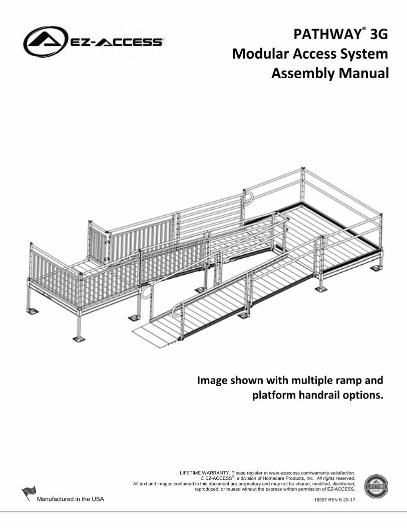
PATHWAY® 3G
Modular Access System Assembly Manual
Image shown with multiple ramp and platform handrail options.

Page 2 of 72
PATHWAY® 3G
Modular Access System Assembly Manual
ATTENTION INSTALLER and END USER • For residential use only! • 1,000 Lb. weight capacity. • Read this manual in its entirety, ensuring you understand all instructions and warnings prior to ramp
assembly and use. • INSTALLER: Please leave this ASSEMBLY MANUAL with the end user. • Please read and become familiar with the ‘MAINTENANCE AND SAFETY’ section of this manual. • Fill out online warranty registration.
TOOLS TYPICALLY REQUIRED 1/2″ SOCKET OR 1/2″ WRENCH 9/16″ SOCKET OR 9/16″ WRENCH 5/16″ SOCKET OR 5/16″ WRENCH LEVEL FILE RUBBER MALLET POWER DRILL 25’ TAPE MEASURE #2 PHILLIPS HEAD SCREW DRIVER PLIERS 5/16″ DRILL BIT (IF BRACE ASSEMBLIES ARE
USED)
5/32″ ALLEN WRENCH (INCLUDED) 3/16″ ALLEN WRENCH (INCLUDED) BOX KNIFE HAMMER 1/4″ MASONRY DRILL BIT (USED WHEN
INSTALLING TO CONCRETE PORCH, STEP, ETC.) DIGGING TOOLS (IF AN OBSTACLE NEEDS TO BE
REMOVED) HACKSAW (FOR OPTIONAL HANDRAIL KITS)
VIEW PACKING LIST Each ramp system is shipped with a packing list. Be sure to check that all items and tools are present before starting installation. SYMBOL MEANINGS
The WARNING symbol indicates a potentially hazardous condition/situation. The safety warnings throughout this manual, and on your equipment, if any, are for the protection of people and property. Failure by any operator to abide by safety warnings will result in a waiver of all liabilities, loss of your warranty, and could result in equipment damage and or failure, property damage, risk of serious bodily injury, and or death. The symbol may appear in various colors and in conjunction with other symbols and with or without the written word “WARNING”.
The NOTE symbol indicates important information. Failure to obey all notes could result in improper operation, less-than-optimum equipment performance, and at the sole discretion of the equipment manufacturer, may void your warranty. The symbol may appear in various colors and in conjunction with other symbols and with or without the written word “NOTE”.

Page 3 of 72
PROPER SET UP AND USE WARNINGS Read and follow all labels, instructions, and warnings prior to assembly and use. To obtain a copy of
complete instructions and warnings, call customer service at 1-800-451-1903. Use caution at all times. Proper maintenance and upkeep to the PATHWAY® 3G Modular Access System
and all PATHWAY® system components is vital. The term “system” refers to the entire PATHWAY 3G Modular Access System, including any gates, stairs,
ramps, platforms, risers, handrails, supports, transition plates, landing pads, and any/all hardware and components which are intended to be assembled on the PATHWAY 3G Modular Access System.
Regularly check that all parts are in good condition and check the system for damage. Ensure all fasteners and locking mechanisms are in place and tightened. If any part of the system is damaged, loose, or missing, DO NOT USE until system repairs can be made by a certified installer or other qualified person.
Do not walk, sit, stand, etc. on the system until the installation is complete. Consult local building codes regarding securing system for wind loads. Use system only with a qualified helper. Keep the system clear of debris and clutter. Do not use if walking surface is unsafe. Confirm the system is correctly leveled and positioned securely. Periodically check for ground shifts. Metal conducts electricity. Do not use near exposed wiring or hang lights from system. Never place anything on, under, or attach anything to system. Only use components supplied or approved by manufacturer with system. Do not sit, stand, or climb on guards, gates, or handrails. Do not use handrails, gates, or any other part of the system, to support planters, decorations, etc. Do not play on or around system, including, but not limited to, running, jumping, bicycles, scooters,
skateboards, etc. Properly support and restrain system in transit or storage. At all times, keep the system clear of dirt, leaves, and other debris that may accumulate on the surface.
Simply sweeping the system or using a garden hose will usually suffice, but, if needed, a damp cloth or soft brush with soap and water can be used (avoid alkaloid detergents). Rinse well and use extra caution when system surface is wet.
The system may be slippery when wet or icy. If system surface is covered with ice and/or snow, DO NOT USE until accumulation is removed and the
tread surface swept clean. Please refer to ‘DEICING SECTION’ of this for more information. Regularly check that all parts are in good condition and check the system for damage. Ensure all fasteners
and locking mechanisms are in place and tightened. If any part of the system is damaged, loose, missing, or unstable DO NOT USE until repairs can be made by a certified installer or other qualified person.
For additional care, usage, or general safety information, please call 1-800-451-1903.
Page 4 of 72
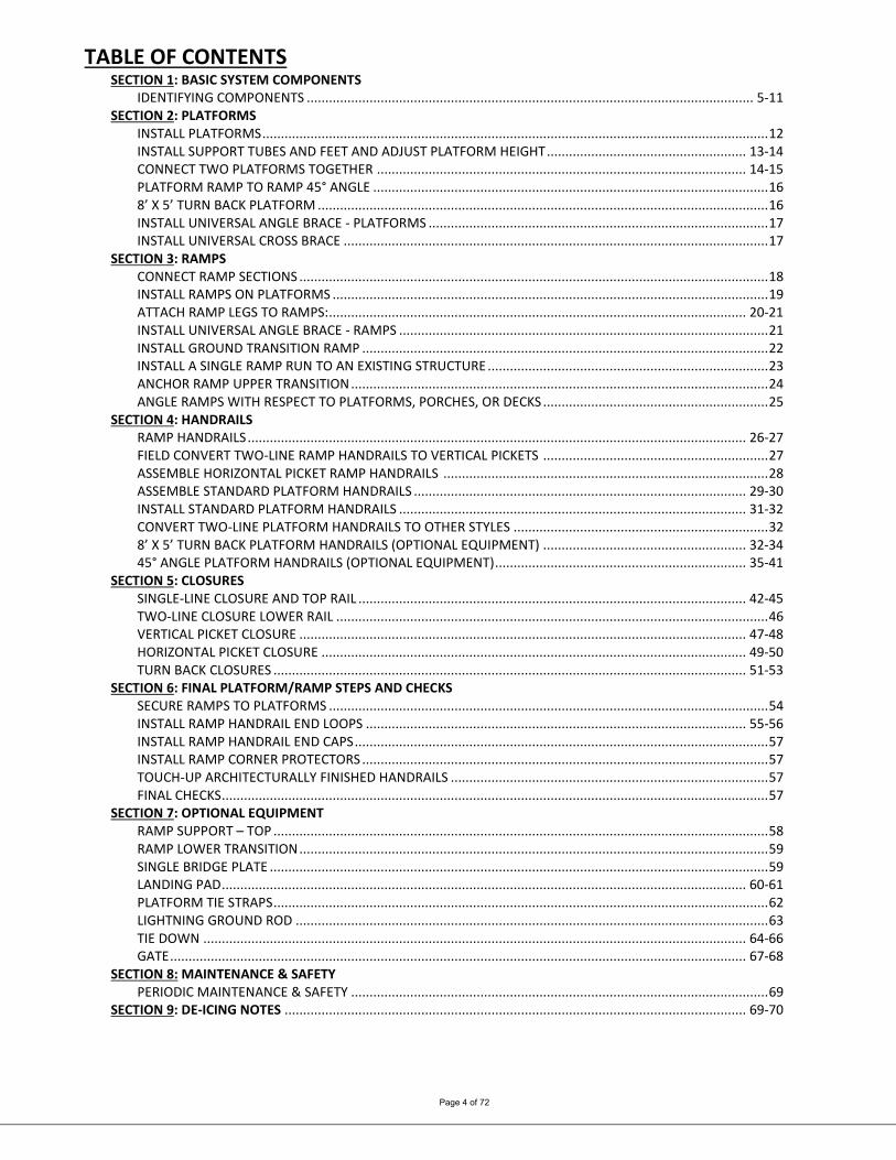
TABLE OF CONTENTS SECTION 1: BASIC SYSTEM COMPONENTS
IDENTIFYING COMPONENTS ......................................................................................................................... 5-11 SECTION 2: PLATFORMS
INSTALL PLATFORMS ......................................................................................................................................... 12 INSTALL SUPPORT TUBES AND FEET AND ADJUST PLATFORM HEIGHT ...................................................... 13-14 CONNECT TWO PLATFORMS TOGETHER .................................................................................................... 14-15 PLATFORM RAMP TO RAMP 45° ANGLE ........................................................................................................... 16 8’ X 5’ TURN BACK PLATFORM .......................................................................................................................... 16 INSTALL UNIVERSAL ANGLE BRACE - PLATFORMS ............................................................................................ 17 INSTALL UNIVERSAL CROSS BRACE ................................................................................................................... 17
SECTION 3: RAMPS CONNECT RAMP SECTIONS ............................................................................................................................... 18 INSTALL RAMPS ON PLATFORMS ...................................................................................................................... 19 ATTACH RAMP LEGS TO RAMPS: ................................................................................................................. 20-21 INSTALL UNIVERSAL ANGLE BRACE - RAMPS .................................................................................................... 21 INSTALL GROUND TRANSITION RAMP .............................................................................................................. 22 INSTALL A SINGLE RAMP RUN TO AN EXISTING STRUCTURE ............................................................................ 23 ANCHOR RAMP UPPER TRANSITION ................................................................................................................. 24 ANGLE RAMPS WITH RESPECT TO PLATFORMS, PORCHES, OR DECKS ............................................................. 25
SECTION 4: HANDRAILS RAMP HANDRAILS ....................................................................................................................................... 26-27 FIELD CONVERT TWO-LINE RAMP HANDRAILS TO VERTICAL PICKETS ............................................................. 27 ASSEMBLE HORIZONTAL PICKET RAMP HANDRAILS ........................................................................................ 28 ASSEMBLE STANDARD PLATFORM HANDRAILS .......................................................................................... 29-30 INSTALL STANDARD PLATFORM HANDRAILS .............................................................................................. 31-32 CONVERT TWO-LINE PLATFORM HANDRAILS TO OTHER STYLES ..................................................................... 32 8’ X 5’ TURN BACK PLATFORM HANDRAILS (OPTIONAL EQUIPMENT) ....................................................... 32-34 45° ANGLE PLATFORM HANDRAILS (OPTIONAL EQUIPMENT) .................................................................... 35-41
SECTION 5: CLOSURES SINGLE-LINE CLOSURE AND TOP RAIL ......................................................................................................... 42-45 TWO-LINE CLOSURE LOWER RAIL ..................................................................................................................... 46 VERTICAL PICKET CLOSURE ......................................................................................................................... 47-48 HORIZONTAL PICKET CLOSURE ................................................................................................................... 49-50 TURN BACK CLOSURES ................................................................................................................................ 51-53
SECTION 6: FINAL PLATFORM/RAMP STEPS AND CHECKS SECURE RAMPS TO PLATFORMS ....................................................................................................................... 54 INSTALL RAMP HANDRAIL END LOOPS ....................................................................................................... 55-56 INSTALL RAMP HANDRAIL END CAPS ................................................................................................................ 57 INSTALL RAMP CORNER PROTECTORS .............................................................................................................. 57 TOUCH-UP ARCHITECTURALLY FINISHED HANDRAILS ...................................................................................... 57 FINAL CHECKS .................................................................................................................................................... 57
SECTION 7: OPTIONAL EQUIPMENT RAMP SUPPORT – TOP ...................................................................................................................................... 58 RAMP LOWER TRANSITION ............................................................................................................................... 59 SINGLE BRIDGE PLATE ....................................................................................................................................... 59 LANDING PAD .............................................................................................................................................. 60-61 PLATFORM TIE STRAPS ...................................................................................................................................... 62 LIGHTNING GROUND ROD ................................................................................................................................ 63 TIE DOWN ................................................................................................................................................... 64-66 GATE ............................................................................................................................................................ 67-68
SECTION 8: MAINTENANCE & SAFETY PERIODIC MAINTENANCE & SAFETY ................................................................................................................. 69
SECTION 9: DE-ICING NOTES ............................................................................................................................. 69-70
Page 5 of 72
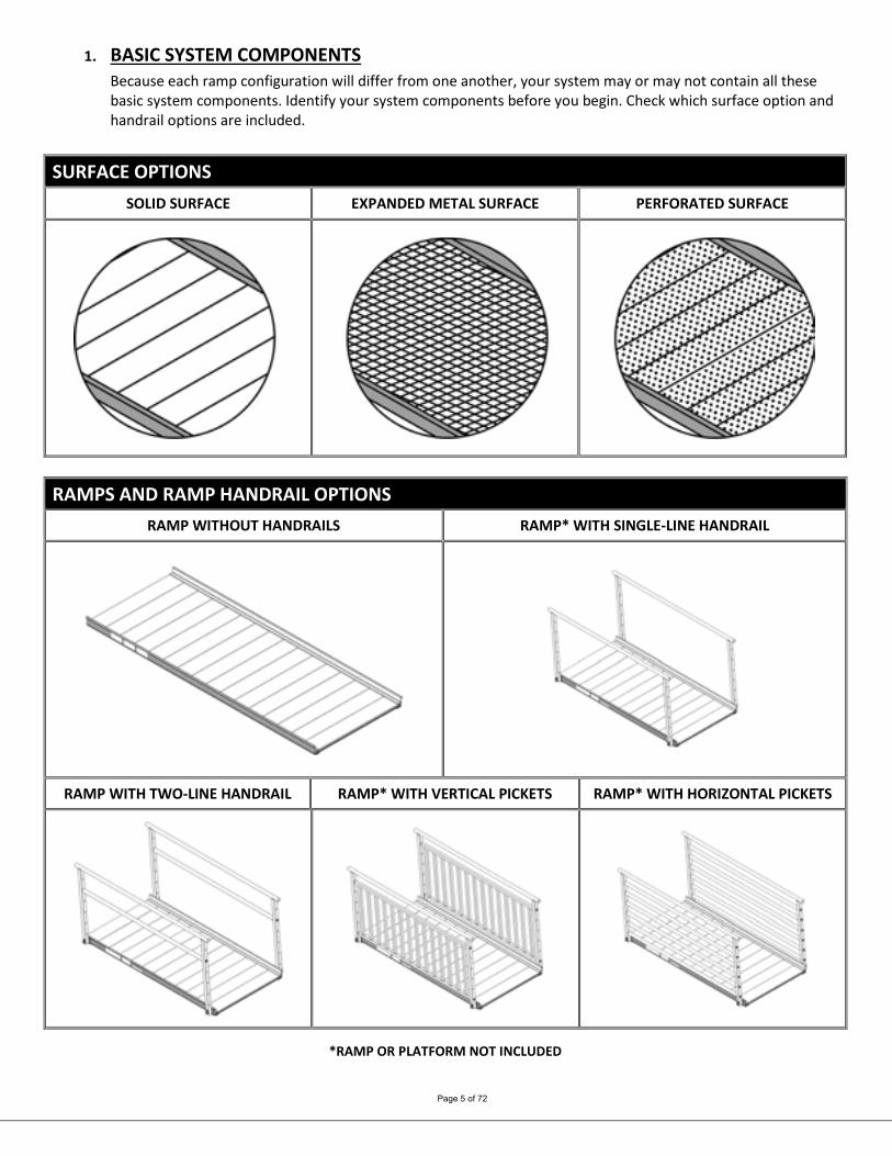
1. BASIC SYSTEM COMPONENTS Because each ramp configuration will differ from one another, your system may or may not contain all these basic system components. Identify your system components before you begin. Check which surface option and handrail options are included.
SURFACE OPTIONS
SOLID SURFACE EXPANDED METAL SURFACE PERFORATED SURFACE
RAMPS AND RAMP HANDRAIL OPTIONS
RAMP WITHOUT HANDRAILS RAMP* WITH SINGLE-LINE HANDRAIL
RAMP WITH TWO-LINE HANDRAIL RAMP* WITH VERTICAL PICKETS RAMP* WITH HORIZONTAL PICKETS
*RAMP OR PLATFORM NOT INCLUDED
Page 6 of 72
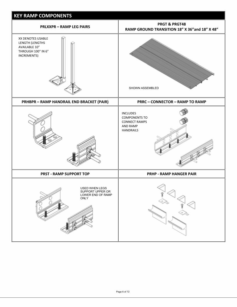
KEY RAMP COMPONENTS
PRLXXPR – RAMP LEG PAIRS PRGT & PRGT48 RAMP GROUND TRANSITION 18” X 36”and 18” X 48”
PRHBPR – RAMP HANDRAIL END BRACKET (PAIR) PRRC – CONNECTOR – RAMP TO RAMP
PRST - RAMP SUPPORT TOP PRHP - RAMP HANGER PAIR
XX DENOTES USABLE LENGTH (LENGTHS AVAILABLE 10” THROUGH 100" IN 6” INCREMENTS)
INCLUDES COMPONENTS TO CONNECT RAMPS AND RAMP HANDRAILS
SHOWN ASSEMBLED
USED WHEN LEGS SUPPORT UPPER OR LOWER END OF RAMP ONLY
Page 7 of 72
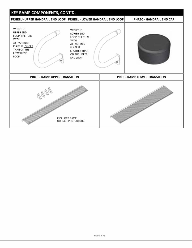
KEY RAMP COMPONENTS, CONT’D. PRHRLU- UPPER HANDRAIL END LOOP PRHRLL - LOWER HANDRAIL END LOOP PHREC - HANDRAIL END CAP
PRUT – RAMP UPPER TRANSITION PRLT – RAMP LOWER TRANSITION
INCLUDES RAMP CORNER PROTECTORS
WITH THE UPPER END LOOP, THE TUBE WITH ATTACHMENT PLATE IS LONGER THAN ON THE LOWER END LOOP
WITH THE LOWER END LOOP, THE TUBE WITH ATTACHMENT PLATE IS SHORTER THAN ON THE UPPER END LOOP

Page 8 of 72
PLATFORMS AND PLATFORM HANDRAIL OPTIONS
PLATFORM (STRAIGHT CONFIGURATION) PLATFORM (TURN CONFIGURATION)
PLATFORM (8’ X 5’ TURN BACK) PLATFORM* WITH SINGLE-LINE HANDRAIL
PLATFORM* WITH VERTICAL PICKET HANDRAIL PLATFORM* WITH HORIZONTAL PICKET HANDRAIL
*RAMP OR PLATFORM NOT INCLUDED
Page 9 of 72
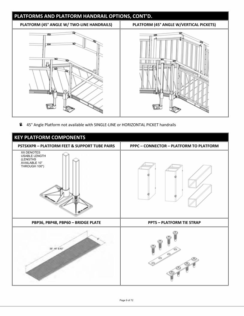
PLATFORMS AND PLATFORM HANDRAIL OPTIONS, CONT’D. PLATFORM (45° ANGLE W/ TWO-LINE HANDRAILS) PLATFORM (45° ANGLE W/VERTICAL PICKETS)
45° Angle Platform not available with SINGLE-LINE or HORIZONTAL PICKET handrails
KEY PLATFORM COMPONENTS
PSTSXXPR – PLATFORM FEET & SUPPORT TUBE PAIRS PPPC – CONNECTOR – PLATFORM TO PLATFORM
PBP36, PBP48, PBP60 – BRIDGE PLATE PPTS – PLATFORM TIE STRAP
XX DENOTES USABLE LENGTH (LENGTHS AVAILABLE 10” THROUGH 100")

Page 10 of 72
CLOSURE OPTIONS
PPCSL – SINGLE-LINE CLOSURE HANDRAIL PPCTL – TWO-LINE CLOSURE HANDRAIL
PPCVP4, PPCVP5, PPCVP5 VERTICAL PICKET CLOSURE HANDRAIL PPCHP – HORIZONTAL PICKET CLOSURE HANDRAIL

Page 11 of 72
ADDITIONAL OPTIONS
PTDK – TIE DOWN KIT PUAB – ANGLE BRACE PUCB4, PUCB5 & PUCB8 – UNIVERSAL CROSS BRACE
PLP – LANDING PAD PUG36 – PATHWAY 3G GATE 36”
• PUCB4 USED ON 4’ PLATFORM SIDE
• PUCB5 USED ON 5’ & 6’ PLATFORM SIDES
• PUCB8 USED ON 8’ PLATFORM SIDE
Page 12 of 72
2. PLATFORMS 2.1. INSTALL PLATFORMS
If your system does not include a platform, skip to ‘CONNECT RAMP SECTIONS’. Platform handrails are shown for clarity of how to orient platforms in various configurations. It
is strongly suggested that all platforms and ramps be installed before installing handrails (see ‘HANDRAILS’ section).
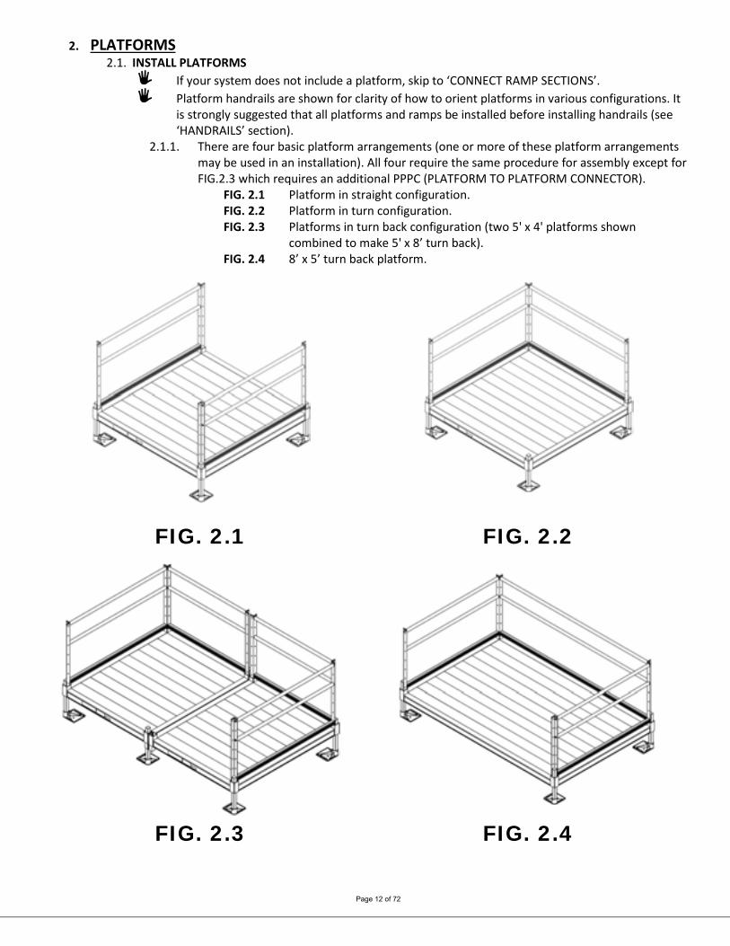
2.1.1. There are four basic platform arrangements (one or more of these platform arrangements may be used in an installation). All four require the same procedure for assembly except for FIG.2.3 which requires an additional PPPC (PLATFORM TO PLATFORM CONNECTOR).
FIG. 2.1 Platform in straight configuration. FIG. 2.2 Platform in turn configuration. FIG. 2.3 Platforms in turn back configuration (two 5' x 4' platforms shown
combined to make 5' x 8’ turn back). FIG. 2.4 8’ x 5’ turn back platform.
FIG. 2.1 FIG. 2.2
FIG. 2.3 FIG. 2.4
Page 13 of 72
2.2. INSTALL SUPPORT TUBES AND FEET, THEN ADJUST PLATFORM HEIGHT 2.2.1. Support tubes, plugs, and feet come in pairs. Support tubes will come in lengths sufficient
for the heights at specific locations. 2.2.2. Loosen all set screws in the platform corner pockets.
2.2.2.1 The set screws on the outside of the platform are for the platform support tubes. 2.2.2.2. The set screws on the inside of the platform (one above the deck and one below the deck) are for the handrail posts.
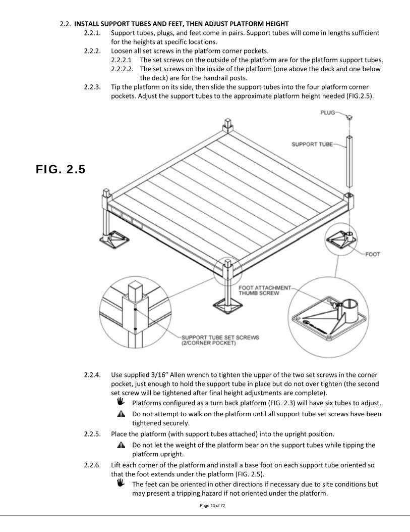
2.2.3. Tip the platform on its side, then slide the support tubes into the four platform corner pockets. Adjust the support tubes to the approximate platform height needed (FIG.2.5).
FIG. 2.5
2.2.4. Use supplied 3/16″ Allen wrench to tighten the upper of the two set screws in the corner pocket, just enough to hold the support tube in place but do not over tighten (the second set screw will be tightened after final height adjustments are complete).
Platforms configured as a turn back platform (FIG. 2.3) will have six tubes to adjust. Do not attempt to walk on the platform until all support tube set screws have been
tightened securely. 2.2.5. Place the platform (with support tubes attached) into the upright position.
Do not let the weight of the platform bear on the support tubes while tipping the platform upright.
2.2.6. Lift each corner of the platform and install a base foot on each support tube oriented so that the foot extends under the platform (FIG. 2.5).
The feet can be oriented in other directions if necessary due to site conditions but may present a tripping hazard if not oriented under the platform.
Page 14 of 72
It is the installer’s responsibility to install the system in a manner which is safe for the persons on and around the system and clearly mark any hazards created by the installation.
2.2.7. Make sure the feet are fully engaged on the tubes and tighten the thumb screw on each foot securely.
If installing on soft soil it may be necessary to set the base foot on a concrete pad. 2.2.8. Adjust the final height of the platform by adjusting legs, one at a time, by loosening the
outer set screws in the platform corner pockets. Using a level, adjust the platform height and re-tighten.
2.2.9. Once the final height has been adjusted, tighten the second, lower set screw in each platform corner pocket.
2.2.10. To allow access to the lowermost hole in the platform post, the support tubes must not extend more than 1/2” above the platform corner pockets. Trim the support tubes as needed before installing plugs.
2.2.11. Insert a plug into the top of each support tubes. Use a rubber mallet or similar tool as needed (FIG.2.5).
2.2.12. Ensure all set screws are tightened securely.
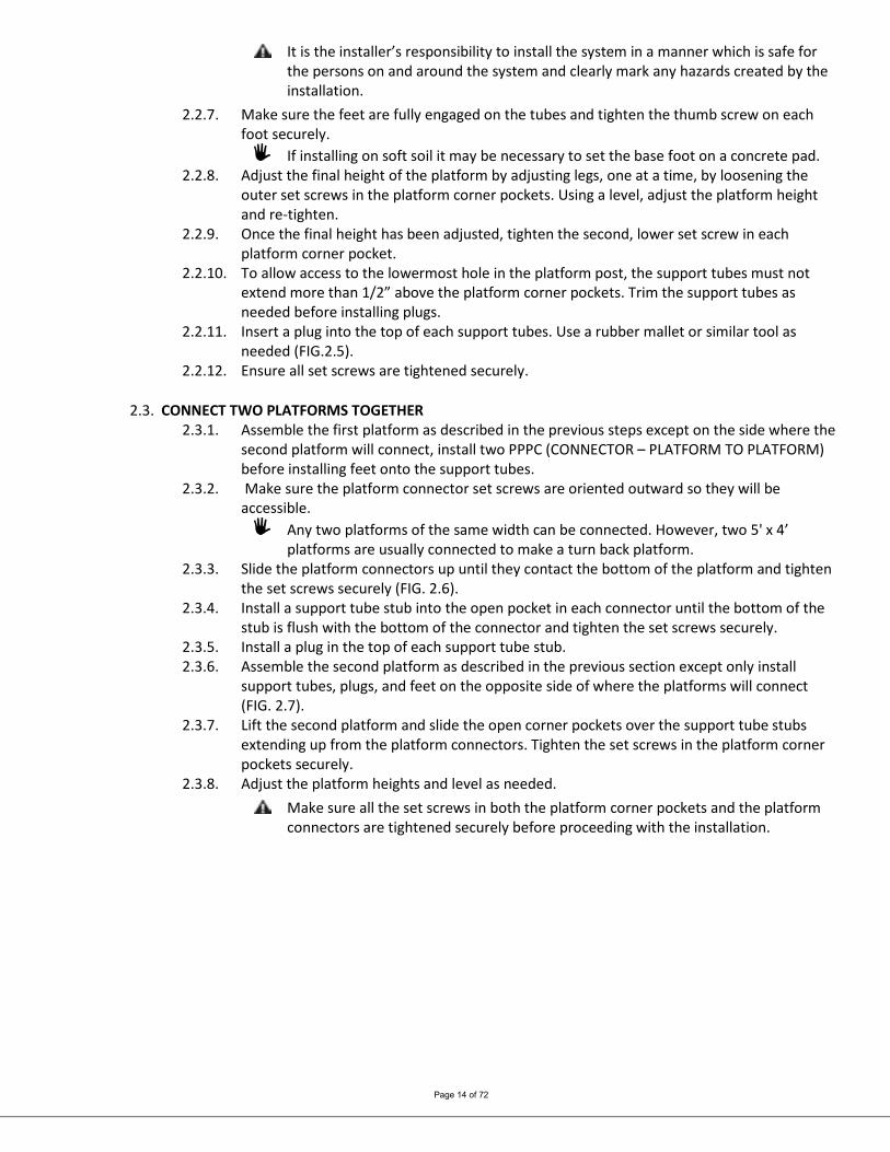
2.3. CONNECT TWO PLATFORMS TOGETHER 2.3.1. Assemble the first platform as described in the previous steps except on the side where the
second platform will connect, install two PPPC (CONNECTOR – PLATFORM TO PLATFORM) before installing feet onto the support tubes.
2.3.2. Make sure the platform connector set screws are oriented outward so they will be accessible.
Any two platforms of the same width can be connected. However, two 5' x 4’ platforms are usually connected to make a turn back platform.
2.3.3. Slide the platform connectors up until they contact the bottom of the platform and tighten the set screws securely (FIG. 2.6).
2.3.4. Install a support tube stub into the open pocket in each connector until the bottom of the stub is flush with the bottom of the connector and tighten the set screws securely.
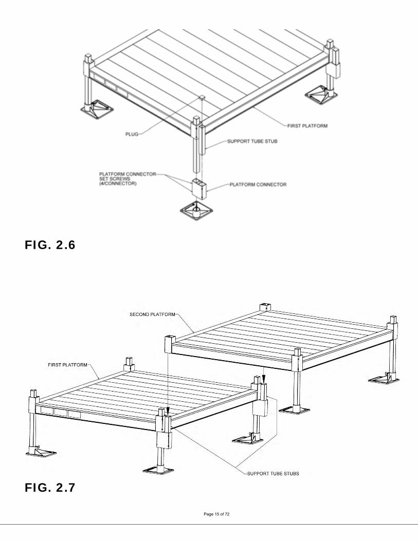
2.3.5. Install a plug in the top of each support tube stub. 2.3.6. Assemble the second platform as described in the previous section except only install
support tubes, plugs, and feet on the opposite side of where the platforms will connect (FIG. 2.7).
2.3.7. Lift the second platform and slide the open corner pockets over the support tube stubs extending up from the platform connectors. Tighten the set screws in the platform corner pockets securely.
2.3.8. Adjust the platform heights and level as needed. Make sure all the set screws in both the platform corner pockets and the platform
connectors are tightened securely before proceeding with the installation.
Page 15 of 72
FIG. 2.6
FIG. 2.7

Page 16 of 72
2.4. 45° ANGLE PLATFORM This platform is used between two ramps to make a 45-degree turn and features a symmetrical design, making it usable in either direction.
2.4.1. There are two options for 45° Angle Platform handrails, Two-Line and Vertical Pickets. The platform includes the handrail components needed for the option ordered.
Platform handrails are shown for clarity of how to orient platforms in various configurations. It is strongly suggested that all platforms and ramps be installed before installing handrails (see ‘HANDRAILS’ section).
2.4.2. Set platform on one of the sides where the ramp will attach and install legs and feet and adjust height as described previously in this section. The two legs on the short side must be installed in the orientation shown (FIG. 2.8)
Use “low profile foot for platform heights under 4”. It is sometimes helpful to lay platform on its side when inserting the legs.
FIG. 2.8 2.4.3. Install ramps on both sides of the platform where there are no curbs. Refer to Section 3.2
for installing ramps on platforms and Section 4 for installing ramp handrails. 2.5. 8’ X 5’ TURN BACK PLATFORM
This platform is used to create a turn back (or switchback) instead of connecting two 5’ x 4’ platforms. It includes two standard 5’ platform handrails and handrails for the 8’ side with a curb.
2.5.1. Install the support tubes and feet as described in the ‘INSTALL SUPPORT TUBES AND FEET, THEN ADJUST PLATFORM HEIGHT’ section.
Page 17 of 72
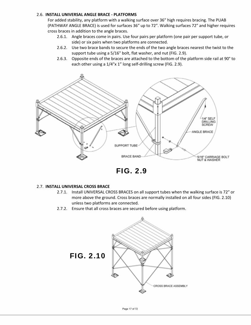
2.6. INSTALL UNIVERSAL ANGLE BRACE - PLATFORMS For added stability, any platform with a walking surface over 36″ high requires bracing. The PUAB (PATHWAY ANGLE BRACE) is used for surfaces 36″ up to 72″. Walking surfaces 72″ and higher requires cross braces in addition to the angle braces.
2.6.1. Angle braces come in pairs. Use four pairs per platform (one pair per support tube, or side) or six pairs when two platforms are connected.
2.6.2. Use two brace bands to secure the ends of the two angle braces nearest the twist to the support tube using a 5/16" bolt, flat washer, and nut (FIG. 2.9).
2.6.3. Opposite ends of the braces are attached to the bottom of the platform side rail at 90° to each other using a 1/4″x 1” long self-drilling screw (FIG. 2.9).
FIG. 2.9
2.7. INSTALL UNIVERSAL CROSS BRACE 2.7.1. Install UNIVERSAL CROSS BRACES on all support tubes when the walking surface is 72″ or
more above the ground. Cross braces are normally installed on all four sides (FIG. 2.10) unless two platforms are connected.
2.7.2. Ensure that all cross braces are secured before using platform.
FIG. 2.10
Page 18 of 72
3. RAMPS 3.1. CONNECT RAMP SECTIONS
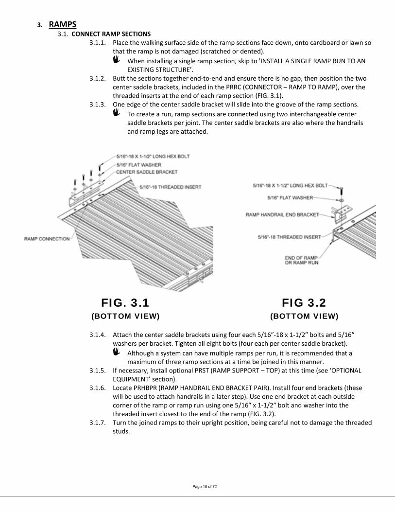
3.1.1. Place the walking surface side of the ramp sections face down, onto cardboard or lawn so that the ramp is not damaged (scratched or dented).
When installing a single ramp section, skip to 'INSTALL A SINGLE RAMP RUN TO AN EXISTING STRUCTURE’.
3.1.2. Butt the sections together end-to-end and ensure there is no gap, then position the two center saddle brackets, included in the PRRC (CONNECTOR – RAMP TO RAMP), over the threaded inserts at the end of each ramp section (FIG. 3.1).
3.1.3. One edge of the center saddle bracket will slide into the groove of the ramp sections. To create a run, ramp sections are connected using two interchangeable center
saddle brackets per joint. The center saddle brackets are also where the handrails and ramp legs are attached.
FIG. 3.1 (BOTTOM VIEW)
FIG 3.2 (BOTTOM VIEW)
3.1.4. Attach the center saddle brackets using four each 5/16″-18 x 1-1/2″ bolts and 5/16″
washers per bracket. Tighten all eight bolts (four each per center saddle bracket). Although a system can have multiple ramps per run, it is recommended that a
maximum of three ramp sections at a time be joined in this manner. 3.1.5. If necessary, install optional PRST (RAMP SUPPORT – TOP) at this time (see ‘OPTIONAL
EQUIPMENT’ section). 3.1.6. Locate PRHBPR (RAMP HANDRAIL END BRACKET PAIR). Install four end brackets (these
will be used to attach handrails in a later step). Use one end bracket at each outside corner of the ramp or ramp run using one 5/16″ x 1-1/2″ bolt and washer into the threaded insert closest to the end of the ramp (FIG. 3.2).
3.1.7. Turn the joined ramps to their upright position, being careful not to damage the threaded studs.

Page 19 of 72
3.2. INSTALL RAMPS ON PLATFORMS 3.2.1. The following will address attaching a ramp or ramp run to a platform. If the ramp needs
to be angled with respect to the platform or is going to be attached to an existing porch, skip to ‘ANGLE RAMPS WITH RESPECT TO PLATFORMS, PORCHES, OR DECKS’ in this section.
3.2.2. Ramps are most commonly located toward either the left or right side of the platform or centered but can be placed in any location on a platform side except when using a ‘VERTICAL PICKET CLOSURE’ (outlined in SECTION 5). When the ramp is located toward the side of a platform, the ramp handrail post should be positioned 1-1/2” (minimum) to 2” from the inside of the platform post. When using other locations, a second closure (Single-Line, Two-Line or Horizontal Picket) must be ordered to connect the ramp and platform handrails. When centering ramps using a Vertical Picket Closure additional components are needed. The additional components will come with the closure if specified at the time of order. The closure can also be converted in the field by ordering a second set of hardware.
3.2.3. Locate a PRHP (RAMP HANGER PAIR) and install the two hangers in the platform side rail where the ramp will be attached.
3.2.4. Hold the hanger perpendicular (approximately) to the platform side rail then bring the hanger upward until it is against the side rail lip. Rotate the hanger and continue pushing upward in such a manner that the “hook″ at the top of the hanger goes behind and catches on the lip in the top of the platform side rail and the hanger sits on the ledge at the bottom (FIG. 3.3).
3.2.5. Set the ramp on the hangers. The hangers should be positioned as close as possible to the ramp side rails. The procedure is the same at both the top and bottom of ramp runs which end at a platform unless a transition plate is used (FIG. 3.4).
Do not attempt to walk on ramps until installation is complete.
FIG. 3.3 (TOP VIEW)
FIG. 3.4 (BOTTOM VIEW)
Page 20 of 72
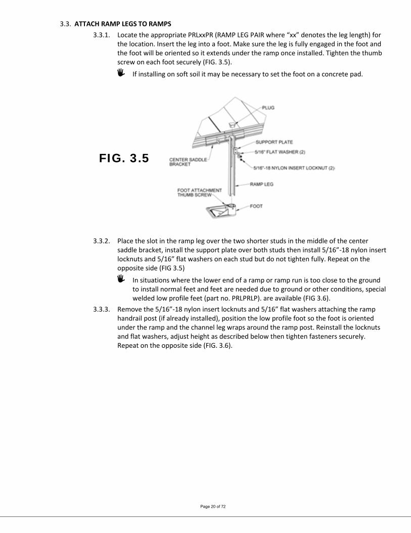
3.3. ATTACH RAMP LEGS TO RAMPS 3.3.1. Locate the appropriate PRLxxPR (RAMP LEG PAIR where “xx” denotes the leg length) for
the location. Insert the leg into a foot. Make sure the leg is fully engaged in the foot and the foot will be oriented so it extends under the ramp once installed. Tighten the thumb screw on each foot securely (FIG. 3.5).
If installing on soft soil it may be necessary to set the foot on a concrete pad.
FIG. 3.5
3.3.2. Place the slot in the ramp leg over the two shorter studs in the middle of the center saddle bracket, install the support plate over both studs then install 5/16”-18 nylon insert locknuts and 5/16” flat washers on each stud but do not tighten fully. Repeat on the opposite side (FIG 3.5)
In situations where the lower end of a ramp or ramp run is too close to the ground to install normal feet and feet are needed due to ground or other conditions, special welded low profile feet (part no. PRLPRLP). are available (FIG 3.6).
3.3.3. Remove the 5/16”-18 nylon insert locknuts and 5/16” flat washers attaching the ramp handrail post (if already installed), position the low profile foot so the foot is oriented under the ramp and the channel leg wraps around the ramp post. Reinstall the locknuts and flat washers, adjust height as described below then tighten fasteners securely. Repeat on the opposite side (FIG. 3.6).

Page 21 of 72
FIG. 3.6
3.3.4. Adjust the ramp legs one at a time. ADA guidelines call for a maximum slope of 1:12 (approximately 5°) and this is the
ideal slope for the PATHWAY 3G system. However, the ramps can be installed from 1:14 to 1:8 (approximately 4° to 7°). Do not attempt to install the ramps outside this range.
NOTE if the ramp is installed at the maximum angle (approximately 7°) longer legs may be required.
3.3.4.1. Raise the ramp sections (at the center saddle bracket) to take any sag out of the ramp run, then tighten the two locknuts in each leg.
Adjusting sections can be accomplished by having someone sight down the ramp while another person adjusts the ramp height.
It’s important to ensure that the ramp sections are parallel to each other. If they are not, it may be difficult to install the handrails (FIG. 3.7).
3.3.4.2. Insert a plug into the top of each leg (FIG. 3.5). 3.3.5. Ensure that all bolts are tight and the ramp sections are aligned parallel to one another.
FIG. 3.7

Page 22 of 72
FIG. 3.8
INSTALL UNIVERSAL ANGLE BRACE - RAMPS
If the ramp walking surface is over 36″ high, a PUAB (UNIVERSAL ANGLE BRACE) must be installed under the ramp (FIG. 3.8).
3.3.6. The opposite end of the angle brace is attached to the bottom of the ramp (near the center of the tread at the end of the ramp) using a 1/4″ x 1” long self-drilling screw.
3.3.7. Ensure that all angle braces are secured before using the ramp. Walking surfaces over 72″ or more above the ground require UNIVERSAL CROSS
BRACES in addition to the angle braces (see ‘INSTALL UNIVERSAL CROSS BRACE’ section). The process for installing cross braces to ramp legs and platform support tubes is the same.
Page 23 of 72
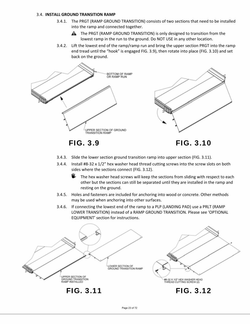
3.4. INSTALL GROUND TRANSITION RAMP 3.4.1. The PRGT (RAMP GROUND TRANSITION) consists of two sections that need to be installed
into the ramp and connected together. The PRGT (RAMP GROUND TRANSITION) is only designed to transition from the
lowest ramp in the run to the ground. Do NOT USE in any other location. 3.4.2. Lift the lowest end of the ramp/ramp run and bring the upper section PRGT into the ramp
end tread until the “hook” is engaged FIG. 3.9), then rotate into place (FIG. 3.10) and set back on the ground.
FIG. 3.9 FIG. 3.10
3.4.3. Slide the lower section ground transition ramp into upper section (FIG. 3.11). 3.4.4. Install #8-32 x 1/2” hex washer head thread cutting screws into the screw slots on both
sides where the sections connect (FIG. 3.12).
The hex washer head screws will keep the sections from sliding with respect to each other but the sections can still be separated until they are installed in the ramp and resting on the ground.
3.4.5. Holes and fasteners are included for anchoring into wood or concrete. Other methods may be used when anchoring into other surfaces.
3.4.6. If connecting the lowest end of the ramp to a PLP (LANDING PAD) use a PRLT (RAMP LOWER TRANSITION) instead of a RAMP GROUND TRANSITION. Please see ‘OPTIONAL EQUIPMENT’ section for instructions.
FIG. 3.11 FIG. 3.12
Page 24 of 72
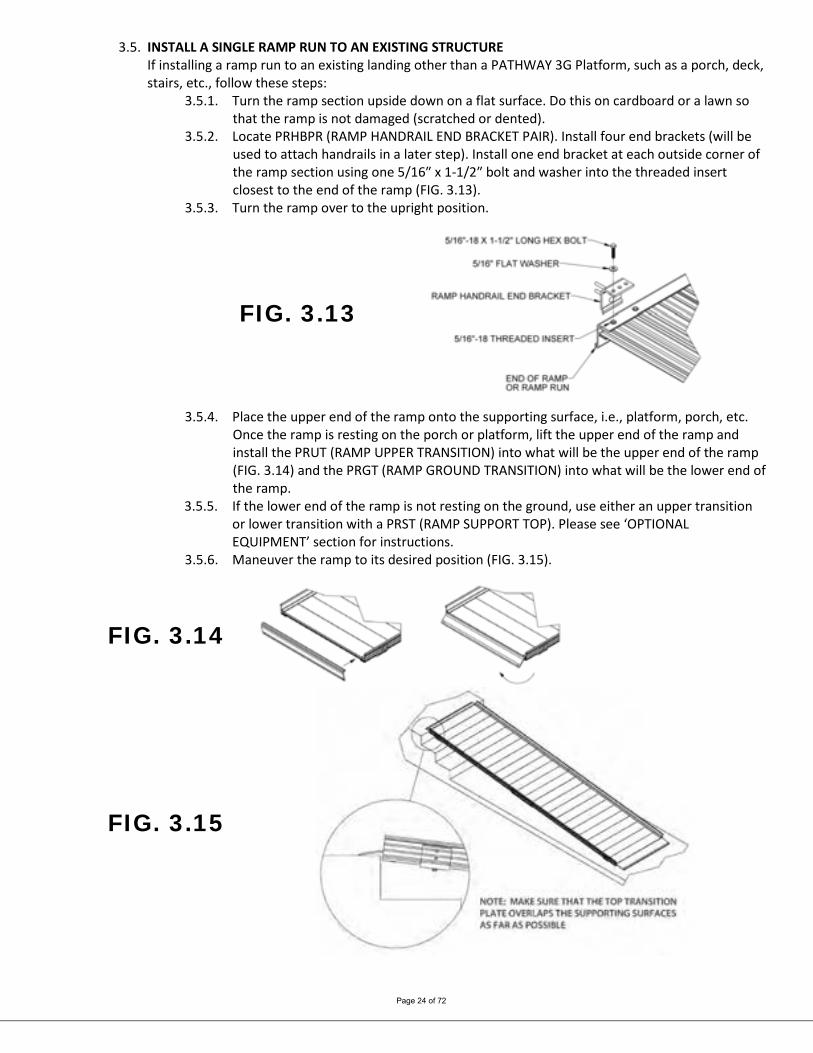
3.5. INSTALL A SINGLE RAMP RUN TO AN EXISTING STRUCTURE If installing a ramp run to an existing landing other than a PATHWAY 3G Platform, such as a porch, deck, stairs, etc., follow these steps:
3.5.1. Turn the ramp section upside down on a flat surface. Do this on cardboard or a lawn so that the ramp is not damaged (scratched or dented).
3.5.2. Locate PRHBPR (RAMP HANDRAIL END BRACKET PAIR). Install four end brackets (will be used to attach handrails in a later step). Install one end bracket at each outside corner of the ramp section using one 5/16″ x 1-1/2″ bolt and washer into the threaded insert closest to the end of the ramp (FIG. 3.13).
3.5.3. Turn the ramp over to the upright position.
FIG. 3.13
3.5.4. Place the upper end of the ramp onto the supporting surface, i.e., platform, porch, etc. Once the ramp is resting on the porch or platform, lift the upper end of the ramp and install the PRUT (RAMP UPPER TRANSITION) into what will be the upper end of the ramp (FIG. 3.14) and the PRGT (RAMP GROUND TRANSITION) into what will be the lower end of the ramp.
3.5.5. If the lower end of the ramp is not resting on the ground, use either an upper transition or lower transition with a PRST (RAMP SUPPORT TOP). Please see ‘OPTIONAL EQUIPMENT’ section for instructions.
3.5.6. Maneuver the ramp to its desired position (FIG. 3.15).
FIG. 3.14
FIG. 3.15
Page 25 of 72
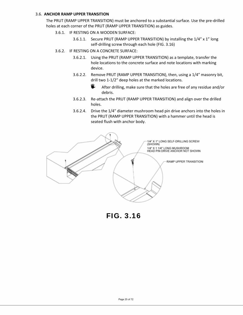
3.6. ANCHOR RAMP UPPER TRANSITION The PRUT (RAMP UPPER TRANSITION) must be anchored to a substantial surface. Use the pre-drilled holes at each corner of the PRUT (RAMP UPPER TRANSITION) as guides.
3.6.1. IF RESTING ON A WOODEN SURFACE: 3.6.1.1. Secure PRUT (RAMP UPPER TRANSITION) by installing the 1/4″ x 1” long
self-drilling screw through each hole (FIG. 3.16) 3.6.2. IF RESTING ON A CONCRETE SURFACE:
3.6.2.1. Using the PRUT (RAMP UPPER TRANSITION) as a template, transfer the hole locations to the concrete surface and note locations with marking device.
3.6.2.2. Remove PRUT (RAMP UPPER TRANSITION), then, using a 1/4″ masonry bit, drill two 1-1/2″ deep holes at the marked locations.
After drilling, make sure that the holes are free of any residue and/or debris.
3.6.2.3. Re-attach the PRUT (RAMP UPPER TRANSITION) and align over the drilled holes.
3.6.2.4. Drive the 1/4″ diameter mushroom head pin drive anchors into the holes in the PRUT (RAMP UPPER TRANSITION) with a hammer until the head is seated flush with anchor body.
FIG. 3.16

Page 26 of 72
3.7. ANGLE RAMPS WITH RESPECT TO PLATFORMS, PORCHES, OR DECKS There are situations where it is necessary to angle ramps with respect to a platform, porch or deck. The components required are not normally included with a typical system unless it is a ramp or ramp run without a platform. If a ramp must be angled when attaching to a platform, a PRUT (RAMP UPPER TRANSITION) or PRLT (RAMP LOWER TRANSITION) with a PRST (RAMP SUPPORT TOP) must be used instead of a PRHP (RAMP HANGER PAIR). The same components can be used at the top and bottom of ramp or ramp runs depending on the angle required.
3.7.1. Angles up to approximately 3° can be accommodated using the PRUT (RAMP UPPER TRANSITION) as long as the PRUT (RAMP UPPER TRANSITION) overlaps the surface of the platform, porch or deck by at least 1” (FIG. 3.17).
3.7.2. Angles up to approximately 6° can be accommodated using the PRLT (RAMP LOWER TRANSITION) with a PRST (RAMP SUPPORT TOP) and ramp legs. Legs must be used on both sides of the ramp when angled over 3°. Refer to the appropriate sections in ‘OPTIONAL EQUIPMENT’ for installing the PRUT (RAMP UPPER TRANSITION) or PRLT (RAMP LOWER TRANSITION) (FIG. 3.18).
3.7.3. The PRLT (RAMP LOWER TRANSITION) should overlap the surface of the platform, porch or deck by at least 1” regardless of the angle required (FIG. 3.18).
FIG. 3.17 FIG. 3.18

Page 27 of 72
4. HANDRAILS 4.1. RAMP HANDRAILS
4.1.1. Two-line handrails are provided in pairs when ordered with the ramp. Other styles of ramp handrails, Single-Line, Vertical Pickets, and Horizontal Pickets, are provided for a single side to allow maximum flexibility in handrail options. Two-line handrails can also be converted to other styles.
4.1.2. One handrail is required on each side of the ramp but handrails are interchangeable side to side.
4.1.3. In a multiple ramp run configuration, handrail connectors (PRRC – CONNECTOR RAMP TO RAMP) are used to join handrails together. Refer to FIGS. 4.1 and 4.2 for the following steps:
4.1.3.1. The vertical posts of the handrails each have two holes which correspond with the studs on the end or center saddle brackets (installed in previous steps).
4.1.3.2. Attach handrails to these studs using two each 5/16″ flat washers and two each 5/16″ nuts per handrail post. Tighten 5/16″ nuts locknuts just enough to hold handrail in place.
If the studs do not align with the posts the handrail, the end saddle bracket is most likely installed into the wrong threaded insert in the ramp side rail. (See FIGS. 3.2 or 3.13 for proper installation location.)
4.1.3.3. Slide the ramp handrail connector into one end of the upper handrail tube. If connector does not fit in the tube, use pliers to lightly compress the
connector while sliding into handrail tube.
4.1.3.4. Slide the next handrail section over the connector, ensuring the upper
handrail tubes are pushed firmly towards each other. Compress the connector and/or use a rubber mallet as needed.
4.1.3.5. Rotate the handrail until the holes in the handrail post align with the studs in the saddle brackets that are connected to the ramp. Attach with 5/16″ flat washers and 5/16″ nuts but tighten only enough to hold the handrail in place.
4.1.3.6. Repeat for the remaining handrails in the run then tighten all the fasteners securely.
FIG. 4.1
Page 28 of 72
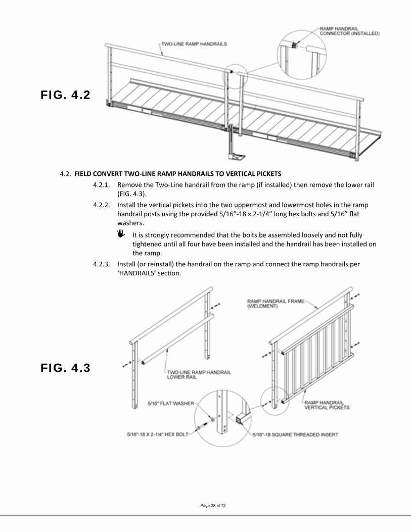
FIG. 4.2
4.2. FIELD CONVERT TWO-LINE RAMP HANDRAILS TO VERTICAL PICKETS
4.2.1. Remove the Two-Line handrail from the ramp (if installed) then remove the lower rail (FIG. 4.3).
4.2.2. Install the vertical pickets into the two uppermost and lowermost holes in the ramp handrail posts using the provided 5/16”-18 x 2-1/4” long hex bolts and 5/16” flat washers.
It is strongly recommended that the bolts be assembled loosely and not fully tightened until all four have been installed and the handrail has been installed on the ramp.
4.2.3. Install (or reinstall) the handrail on the ramp and connect the ramp handrails per ‘HANDRAILS’ section.
FIG. 4.3
Page 29 of 72
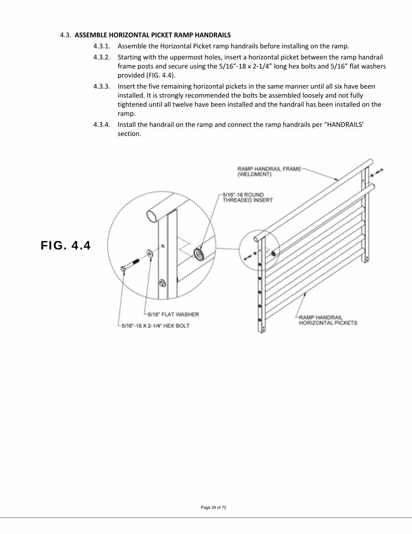
4.3. ASSEMBLE HORIZONTAL PICKET RAMP HANDRAILS
4.3.1. Assemble the Horizontal Picket ramp handrails before installing on the ramp. 4.3.2. Starting with the uppermost holes, insert a horizontal picket between the ramp handrail
frame posts and secure using the 5/16”-18 x 2-1/4” long hex bolts and 5/16” flat washers provided (FIG. 4.4).
4.3.3. Insert the five remaining horizontal pickets in the same manner until all six have been installed. It is strongly recommended the bolts be assembled loosely and not fully tightened until all twelve have been installed and the handrail has been installed on the ramp.
4.3.4. Install the handrail on the ramp and connect the ramp handrails per “HANDRAILS’ section.
FIG. 4.4
Page 30 of 72
4.4. ASSEMBLE STANDARD PLATFORM HANDRAILS 4.4.1. Two-Line and Single-Line handrails are provided in pairs when ordered with the
PATHWAY 3G platform. Vertical Pickets & Horizontal Pickets are provided for a single side to allow maximum flexibility in handrail options. When Vertical Pickets or Horizontal Pickets are ordered, you will receive a platform with Two-Line handrails and the picket option(s) ordered. Two-Line handrails can also be converted to other styles in the field, see Section 4.6. Regardless of style, it is strongly recommended the bolts be assembled loosely and not fully tightened until all have been installed and the handrail has been installed in the platform.
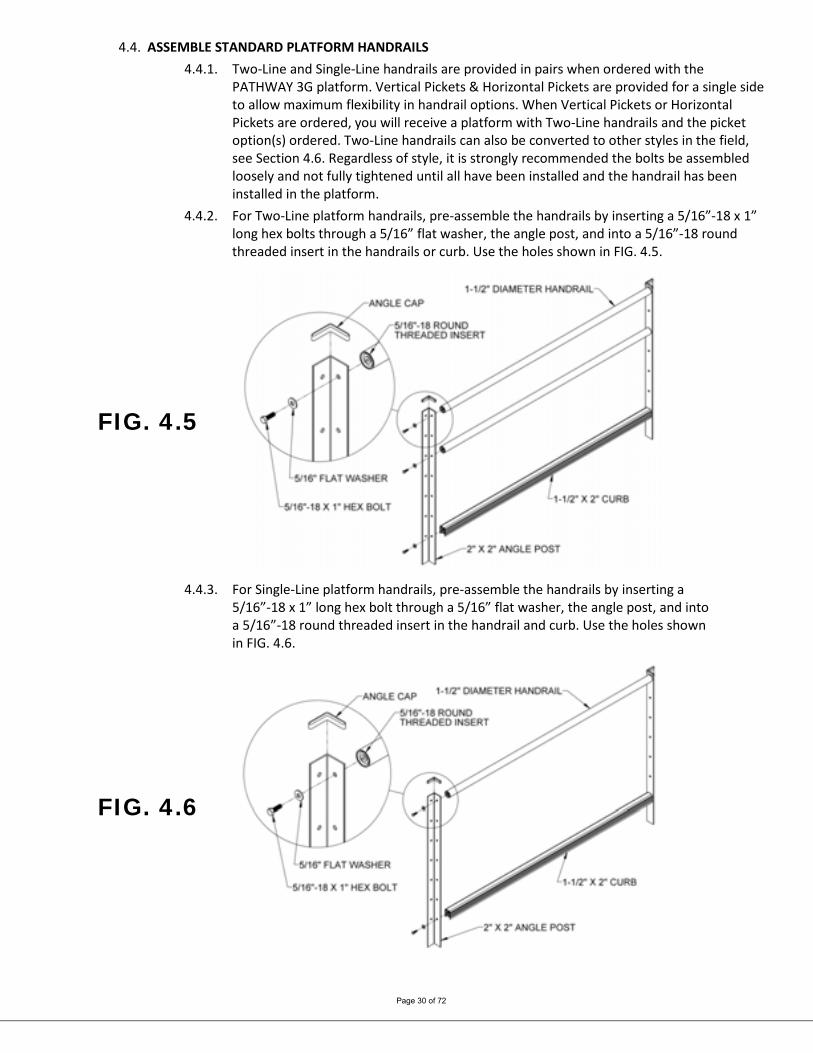
4.4.2. For Two-Line platform handrails, pre-assemble the handrails by inserting a 5/16”-18 x 1” long hex bolts through a 5/16” flat washer, the angle post, and into a 5/16”-18 round threaded insert in the handrails or curb. Use the holes shown in FIG. 4.5.
FIG. 4.5
4.4.3. For Single-Line platform handrails, pre-assemble the handrails by inserting a
5/16”-18 x 1” long hex bolt through a 5/16” flat washer, the angle post, and into a 5/16”-18 round threaded insert in the handrail and curb. Use the holes shown in FIG. 4.6.
FIG. 4.6

Page 31 of 72
4.4.4. For Vertical Picket platform handrails, pre-assemble the handrails by inserting a 5/16”-18 x 1” long hex bolts through a 5/16” flat washer, the angle post, and into a 5/16”-18 round threaded insert in the handrail or square threaded insert in the vertical pickets. Use the holes shown in FIG. 4.7.
FIG. 4.7
4.4.5. For Horizontal Picket platform handrails, pre-assemble the handrails by inserting a 5/16”-18 x 1” long hex bolt through a 5/16” flat washer, the angle post, and into a 5/16”-18 round threaded insert in the handrails and curb. Use the holes shown in FIG. 4.8.
FIG. 4.8

Page 32 of 72
4.5. INSTALL STANDARD PLATFORM HANDRAILS 4.5.1. Regardless of the handrail style, but depending on the configuration, refer to FIG. 4.9 and
FIG. 4.10 as needed. 4.5.2. Pre-assemble the platform handrail for both sides of a straight configuration and the
“first″ handrail of a turn configuration as described above. Make sure the unattached legs of the angle posts are on the same side with respect to the handrail tubes, curb and pickets and pointing outward as shown.
4.5.3. For the “second″ handrail in a turn configuration, only assemble one angle post as described above paying attention to how it will connect to the “first″ handrail so the angle post will be oriented correctly.
4.5.4. For straight platform configurations and the “first″ handrail on a turn platform, drop platform handrails into the corner pockets (FIG. 4.9). The curb should rest on top of the corner pocket when installing the Two-Line and Single-Line handrails. For the Vertical Picket and Horizontal Picket handrails, align the bottom of the post with the bottom of the platform corner pockets.
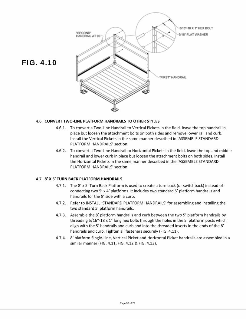
4.5.5. For the “second″ handrail on a turn platform, insert the angle post into a corner pocket at 90° from the “first″ handrail, then install 5/16”-18 x 1” long hex bolts through a 5/16” flat washer, the angle post in the “first” handrail and into a 5/16”-18 threaded inserts in the “second” handrail, curb or picket (FIG. 4.10). Tighten all fasteners securely.
4.5.6. Tighten two each set screws on the inside of the platform corner pocket with a 3/16″ Allen wrench.
4.5.6.1. One setscrews is located above the platform deck and the other is underneath (FIG. 4.9).
4.5.7. Install the plastic angle caps on top of all handrail posts. 4.5.7.1. Glue in place using construction adhesive as needed.
4.5.8. Tighten all fasteners securely if not done in earlier steps.
FIG. 4.9
Page 33 of 72
FIG. 4.10
4.6. CONVERT TWO-LINE PLATFORM HANDRAILS TO OTHER STYLES 4.6.1. To convert a Two-Line Handrail to Vertical Pickets in the field, leave the top handrail in
place but loosen the attachment bolts on both sides and remove lower rail and curb. Install the Vertical Pickets in the same manner described in ‘ASSEMBLE STANDARD PLATFORM HANDRAILS’ section.
4.6.2. To convert a Two-Line Handrail to Horizontal Pickets in the field, leave the top and middle handrail and lower curb in place but loosen the attachment bolts on both sides. Install the Horizontal Pickets in the same manner described in the ‘ASSEMBLE STANDARD PLATFORM HANDRAILS’ section.
4.7. 8’ X 5’ TURN BACK PLATFORM HANDRAILS
4.7.1. The 8’ x 5’ Turn Back Platform is used to create a turn back (or switchback) instead of connecting two 5’ x 4’ platforms. It includes two standard 5’ platform handrails and handrails for the 8’ side with a curb.
4.7.2. Refer to INSTALL ‘STANDARD PLATFORM HANDRAILS’ for assembling and installing the two standard 5’ platform handrails.
4.7.3. Assemble the 8’ platform handrails and curb between the two 5’ platform handrails by threading 5/16"-18 x 1” long hex bolts through the holes in the 5’ platform posts which align with the 5’ handrails and curb and into the threaded inserts in the ends of the 8’ handrails and curb. Tighten all fasteners securely (FIG. 4.11).
4.7.4. 8’ platform Single-Line, Vertical Picket and Horizontal Picket handrails are assembled in a similar manner (FIG. 4.11, FIG. 4.12 & FIG. 4.13).

Page 34 of 72
FIG. 4.11
FIG. 4.12

Page 35 of 72
FIG. 4.13
FIG. 4.14
Page 36 of 72
4.8. 45° ANGLE PLATFORM HANDRAILS 4.8.1. There are two options for 45° Angle Platform handrails, Two-Line and Vertical Pickets.
The platform includes the handrail components needed for the option ordered. Single-Line and Horizontal Picket handrail options are not available for the 45° Angle
Platform. 4.8.2. Assembling either 45° Angle Platform Two-Line or Vertical Pickets handrails should be
completed after all ramps and platforms have been set and the ramp handrails installed. The ramps on both sides of the 45° Angle Platform should be set as close to the corner pockets on the “long” side of the platform as possible. Refer to the following steps for Two-Line handrails. Skip to 4.8.15 for Vertical Pickets handrails.
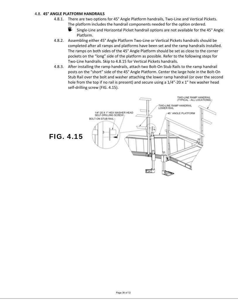
4.8.3. After installing the ramp handrails, attach two Bolt-On Stub Rails to the ramp handrail posts on the “short” side of the 45° Angle Platform. Center the large hole in the Bolt-On Stub Rail over the bolt and washer attaching the lower ramp handrail (or over the second hole from the top if no rail is present) and secure using a 1/4”-20 x 1” hex washer head self-drilling screw (FIG. 4.15).
FIG. 4.15
Page 37 of 72
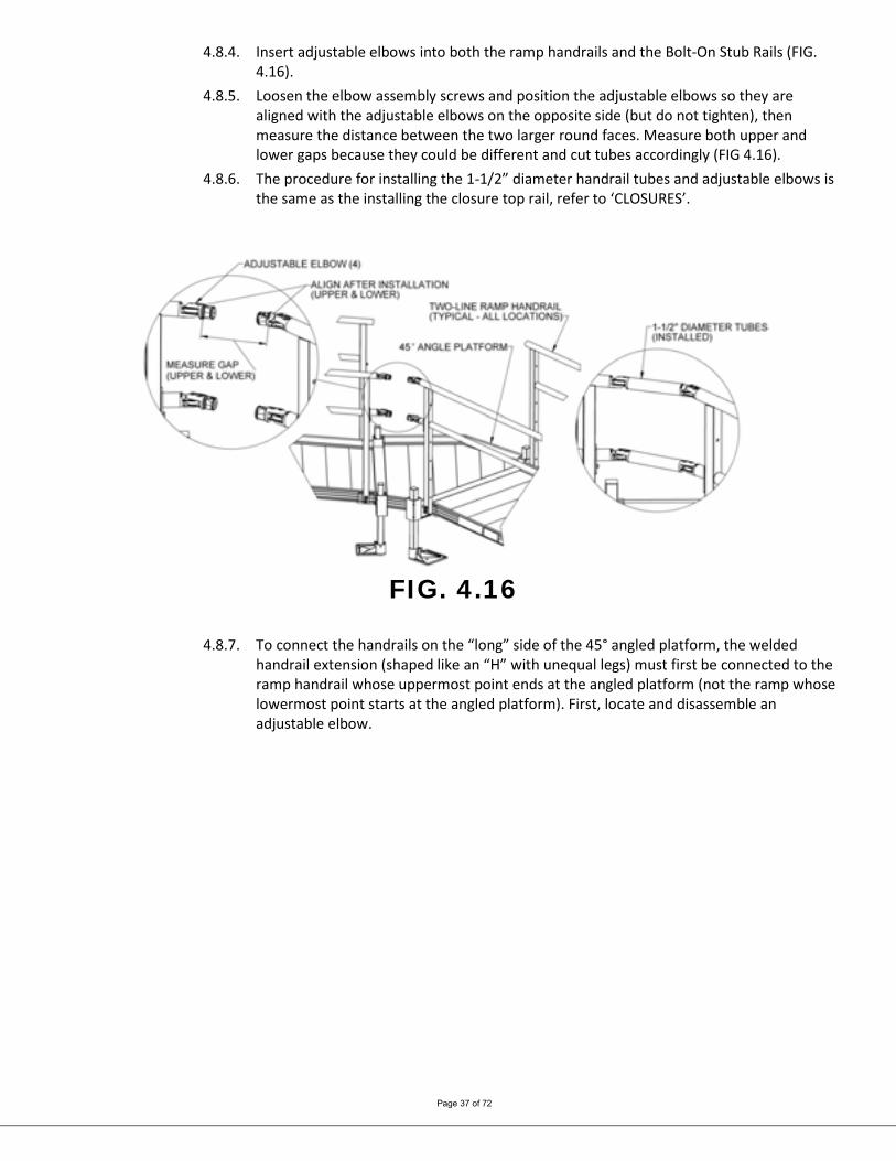
4.8.4. Insert adjustable elbows into both the ramp handrails and the Bolt-On Stub Rails (FIG. 4.16).
4.8.5. Loosen the elbow assembly screws and position the adjustable elbows so they are aligned with the adjustable elbows on the opposite side (but do not tighten), then measure the distance between the two larger round faces. Measure both upper and lower gaps because they could be different and cut tubes accordingly (FIG 4.16).
4.8.6. The procedure for installing the 1-1/2” diameter handrail tubes and adjustable elbows is the same as the installing the closure top rail, refer to ‘CLOSURES’.
FIG. 4.16
4.8.7. To connect the handrails on the “long” side of the 45° angled platform, the welded
handrail extension (shaped like an “H” with unequal legs) must first be connected to the ramp handrail whose uppermost point ends at the angled platform (not the ramp whose lowermost point starts at the angled platform). First, locate and disassemble an adjustable elbow.
Page 38 of 72
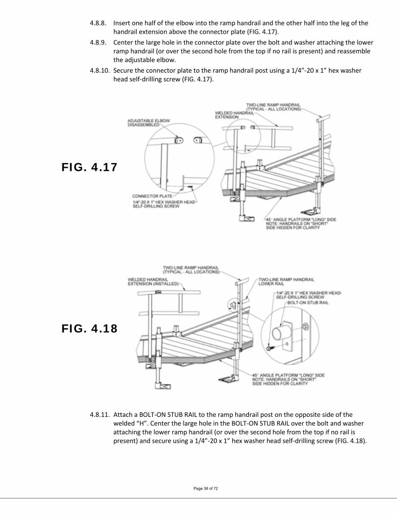
4.8.8. Insert one half of the elbow into the ramp handrail and the other half into the leg of the handrail extension above the connector plate (FIG. 4.17).
4.8.9. Center the large hole in the connector plate over the bolt and washer attaching the lower ramp handrail (or over the second hole from the top if no rail is present) and reassemble the adjustable elbow.
4.8.10. Secure the connector plate to the ramp handrail post using a 1/4”-20 x 1” hex washer head self-drilling screw (FIG. 4.17).
FIG. 4.17
FIG. 4.18
4.8.11. Attach a BOLT-ON STUB RAIL to the ramp handrail post on the opposite side of the welded “H”. Center the large hole in the BOLT-ON STUB RAIL over the bolt and washer attaching the lower ramp handrail (or over the second hole from the top if no rail is present) and secure using a 1/4”-20 x 1” hex washer head self-drilling screw (FIG. 4.18).
Page 39 of 72
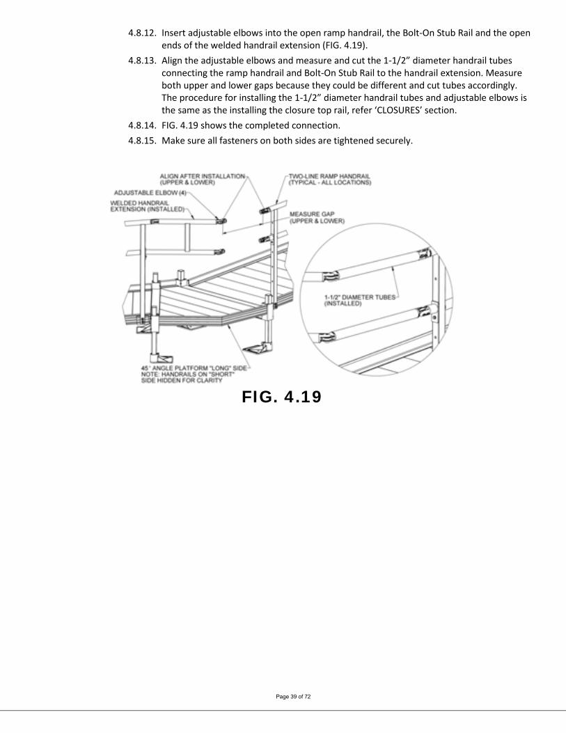
4.8.12. Insert adjustable elbows into the open ramp handrail, the Bolt-On Stub Rail and the open ends of the welded handrail extension (FIG. 4.19).
4.8.13. Align the adjustable elbows and measure and cut the 1-1/2” diameter handrail tubes connecting the ramp handrail and Bolt-On Stub Rail to the handrail extension. Measure both upper and lower gaps because they could be different and cut tubes accordingly. The procedure for installing the 1-1/2” diameter handrail tubes and adjustable elbows is the same as the installing the closure top rail, refer ‘CLOSURES’ section.
4.8.14. FIG. 4.19 shows the completed connection. 4.8.15. Make sure all fasteners on both sides are tightened securely.
FIG. 4.19
Page 40 of 72
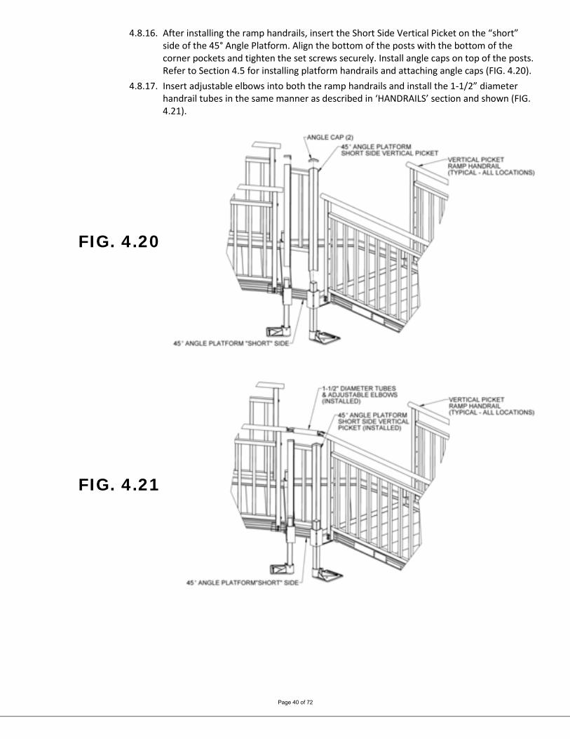
4.8.16. After installing the ramp handrails, insert the Short Side Vertical Picket on the “short” side of the 45° Angle Platform. Align the bottom of the posts with the bottom of the corner pockets and tighten the set screws securely. Install angle caps on top of the posts. Refer to Section 4.5 for installing platform handrails and attaching angle caps (FIG. 4.20).
4.8.17. Insert adjustable elbows into both the ramp handrails and install the 1-1/2” diameter handrail tubes in the same manner as described in ‘HANDRAILS’ section and shown (FIG. 4.21).
FIG. 4.20
FIG. 4.21
Page 41 of 72
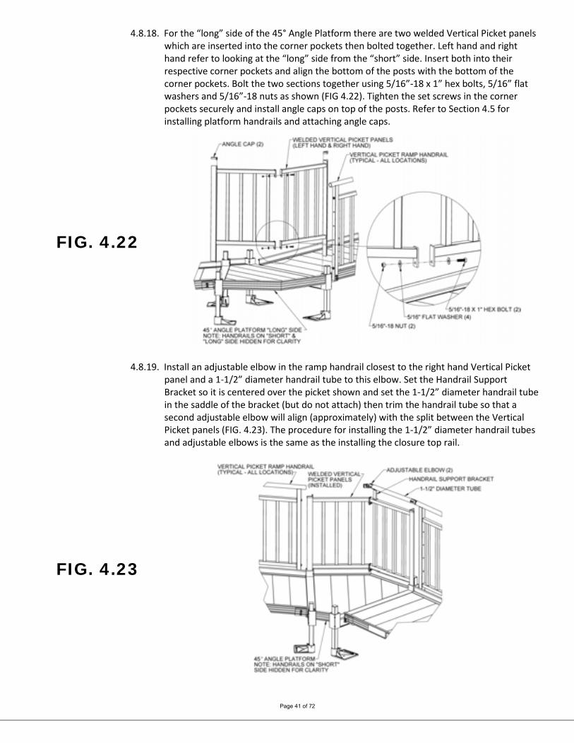
4.8.18. For the “long” side of the 45° Angle Platform there are two welded Vertical Picket panels which are inserted into the corner pockets then bolted together. Left hand and right hand refer to looking at the “long” side from the “short” side. Insert both into their respective corner pockets and align the bottom of the posts with the bottom of the corner pockets. Bolt the two sections together using 5/16”-18 x 1” hex bolts, 5/16” flat washers and 5/16”-18 nuts as shown (FIG 4.22). Tighten the set screws in the corner pockets securely and install angle caps on top of the posts. Refer to Section 4.5 for installing platform handrails and attaching angle caps.
FIG. 4.22
4.8.19. Install an adjustable elbow in the ramp handrail closest to the right hand Vertical Picket panel and a 1-1/2” diameter handrail tube to this elbow. Set the Handrail Support Bracket so it is centered over the picket shown and set the 1-1/2” diameter handrail tube in the saddle of the bracket (but do not attach) then trim the handrail tube so that a second adjustable elbow will align (approximately) with the split between the Vertical Picket panels (FIG. 4.23). The procedure for installing the 1-1/2” diameter handrail tubes and adjustable elbows is the same as the installing the closure top rail.
FIG. 4.23
Page 42 of 72
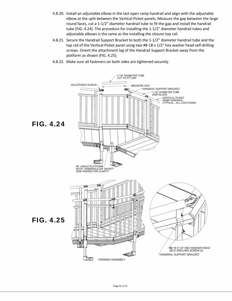
4.8.20. Install an adjustable elbow in the last open ramp handrail and align with the adjustable elbow at the split between the Vertical Picket panels. Measure the gap between the large round faces, cut a 1-1/2” diameter handrail tube to fit the gap and install the handrail tube (FIG. 4.24). The procedure for installing the 1-1/2” diameter handrail tubes and adjustable elbows is the same as the installing the closure top rail.
4.8.21. Secure the Handrail Support Bracket to both the 1-1/2” diameter handrail tube and the top rail of the Vertical Picket panel using two #8-18 x 1/2” hex washer head self-drilling screws. Orient the attachment leg of the Handrail Support Bracket away from the platform as shown (FIG. 4.25).
4.8.22. Make sure all fasteners on both sides are tightened securely.
FIG. 4.24
FIG. 4.25

Page 43 of 72
5. CLOSURES Closures fill the space between ramp handrails and platform posts. Like the ramp and platform handrails, they are available in Two-Line, Single-Line, Vertical Pickets and Horizontal Pickets. As a standard, the closures come with components which require the ramp to be mounted to one side or the other of a platform but the ramp can also be centered or mounted in any location on a platform side except when using the Vertical Picket closure (refer to Section 5.3). When centering the ramp or mounting in a location other than the side, a second Two-Line, Single-Line or Horizontal Picket closure must be ordered and is installed in the same manner as described below. When mounting to the side, the ramp handrail post should be positioned 1-1/2” (minimum) to 2” from the inside of the platform post. For a Single Line closure the steps in this section complete the installation.
5.1. If installing a closure on a platform in the “straight” configuration, the 2” x 2” angle post will already be in place. Skip to 5.1.4
5.2. If installing on a platform in the “turn” configuration, install the 2” x 2” angle post not attached to a platform handrail in the open platform corner pocket. Align the bottom of the post with the bottom of the corner pocket and tighten the set screws securely (FIG. 5.1). Refer to Section 4.5 for addition details on securing the post.
5.3. Install the angle cap on top of the post. Glue in place using construction adhesive as needed. 5.4. First install the top rail, the rail connecting the ramp handrail to the platform post.
This procedure is the same regardless of the style of closure. Insert an adjustable elbow in the ramp handrail. Loosen the elbow assembly screws and position the round portion of the adjustable elbow so it is aligned with the upper hole in the angle post and the face is parallel to the post. Measure the gap between the face and the post (FIG. 5.2).
FIG. 5.1 FIG. 5.2

Page 44 of 72
5.4.1. Cut the 1-1/2″ diameter round tube to the length measured less 1/16” (FIG. 5.3). 5.4.2. Using a metal file, smooth any sharp edges from the cutting. 5.4.3. Disassemble the adjustable elbow by removing the screw, nut and center insert (FIG. 5.4). 5.4.4. Install an elbow half into the end of the cut tube which will attach to the ramp handrail
and a 5/16”-18 round threaded insert into the end which will attach to the post (FIG. 5.3). 5.4.5. Tighten internal set screws of the adjustable elbow using an Allen wrench (FIG. 5.4). 5.4.6. Reassemble elbow by replacing center insert and securing with screw and nut (FIG. 5.5).
FIG. 5.3
FIG. 5.4
FIG. 5.5
Page 45 of 72
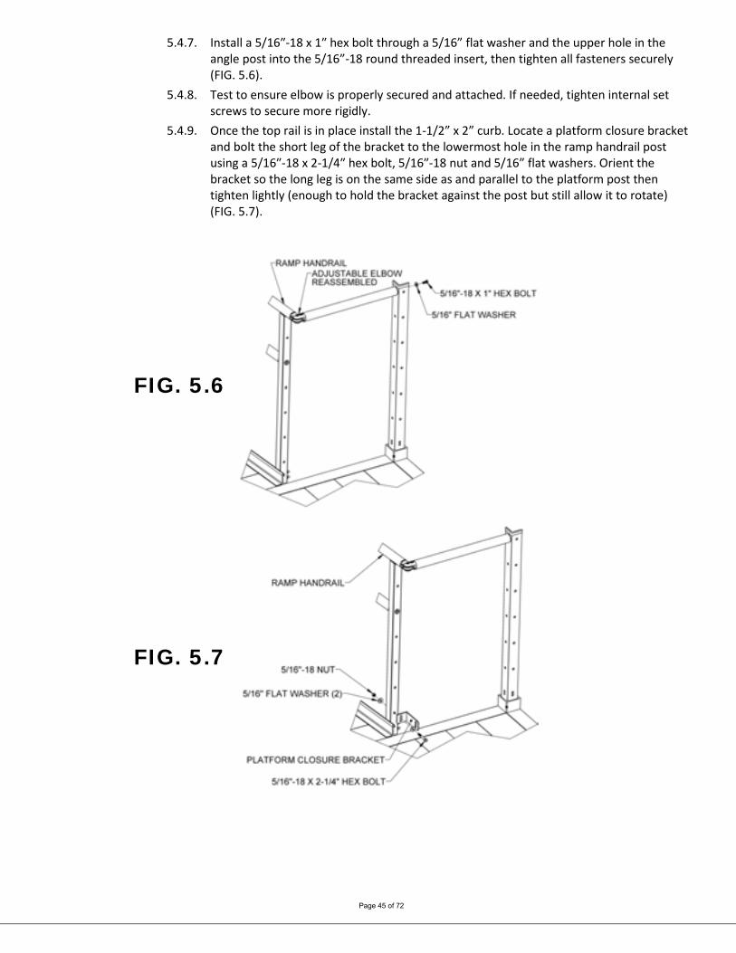
5.4.7. Install a 5/16″-18 x 1″ hex bolt through a 5/16” flat washer and the upper hole in the angle post into the 5/16”-18 round threaded insert, then tighten all fasteners securely (FIG. 5.6).
5.4.8. Test to ensure elbow is properly secured and attached. If needed, tighten internal set screws to secure more rigidly.
5.4.9. Once the top rail is in place install the 1-1/2” x 2” curb. Locate a platform closure bracket and bolt the short leg of the bracket to the lowermost hole in the ramp handrail post using a 5/16″-18 x 2-1/4″ hex bolt, 5/16″-18 nut and 5/16” flat washers. Orient the bracket so the long leg is on the same side as and parallel to the platform post then tighten lightly (enough to hold the bracket against the post but still allow it to rotate) (FIG. 5.7).
FIG. 5.6
FIG. 5.7
Page 46 of 72
FIG. 5.8
FIG. 5.9
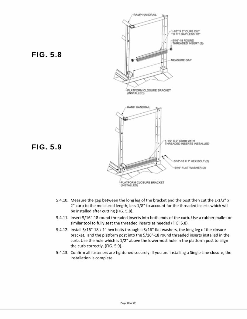
5.4.10. Measure the gap between the long leg of the bracket and the post then cut the 1-1/2” x 2” curb to the measured length, less 1/8” to account for the threaded inserts which will be installed after cutting (FIG. 5.8).
5.4.11. Insert 5/16”-18 round threaded inserts into both ends of the curb. Use a rubber mallet or similar tool to fully seat the threaded inserts as needed (FIG. 5.8).
5.4.12. Install 5/16″-18 x 1″ hex bolts through a 5/16” flat washers, the long leg of the closure bracket, and the platform post into the 5/16”-18 round threaded inserts installed in the curb. Use the hole which is 1/2” above the lowermost hole in the platform post to align the curb correctly. (FIG. 5.9).
5.4.13. Confirm all fasteners are tightened securely. If you are installing a Single Line closure, the installation is complete.
Page 47 of 72
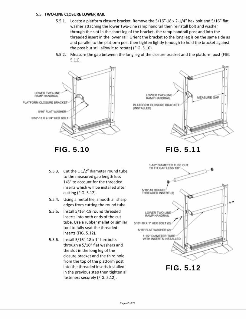
5.5. TWO-LINE CLOSURE LOWER RAIL 5.5.1. Locate a platform closure bracket. Remove the 5/16″-18 x 2-1/4″ hex bolt and 5/16” flat
washer attaching the lower Two-Line ramp handrail then reinstall bolt and washer through the slot in the short leg of the bracket, the ramp handrail post and into the threaded insert in the lower rail. Orient the bracket so the long leg is on the same side as and parallel to the platform post then tighten lightly (enough to hold the bracket against the post but still allow it to rotate) (FIG. 5.10).
5.5.2. Measure the gap between the long leg of the closure bracket and the platform post (FIG. 5.11).
FIG. 5.10 FIG. 5.11
5.5.3. Cut the 1 1/2″ diameter round tube to the measured gap length less 1/8” to account for the threaded inserts which will be installed after cutting (FIG. 5.12).
5.5.4. Using a metal file, smooth all sharp edges from cutting the round tube.
5.5.5. Install 5/16”-18 round threaded inserts into both ends of the cut tube. Use a rubber mallet or similar tool to fully seat the threaded inserts (FIG. 5.12).
5.5.6. Install 5/16″-18 x 1″ hex bolts through a 5/16” flat washers and the slot in the long leg of the closure bracket and the third hole from the top of the platform post into the threaded inserts installed in the previous step then tighten all fasteners securely (FIG. 5.12).
FIG. 5.12

Page 48 of 72
5.6. VERTICAL PICKET CLOSURE 5.6.1. Vertical Picket closures are specific to the platform size (4’, 5’ and 6’) and come in two
pieces which allow the ramp to be mounted to one side or be centered on a platform side. If the ramp is to be centered on a platform additional components are needed. The additional components will come with the closure if specified at the time of order but the closure can be converted to allow the ramp to be centered in the field by ordering a second set of hardware. Locate the correct Vertical Picket closure for the platform.
5.6.2. Bolt the two Vertical Picket closure sections together using 5/16”-18 x 3/4” long hex bolts, 5/16” flat washers, and 5/16”-18 nuts (as shown in FIG 5.13). Then, Insert 1-1/4” square tube plugs in the open ends of the top and bottom rails on one side. If the ramp will be centered, do not assemble. Insert 1-1/4” square tube plugs in all open ends which do not attach to a platform post.
The 4’ closure includes angles (rather than channels) on one side to allow access to the assembly fasteners. Always bolt the 4’ closure together using the side with the angles and attach the side with the channel to the platform post (FIG. 5.14).
FIG. 5.13 FIG. 5.14
5.6.3. Attach the Vertical Picket closure to the platform handrail post using 5/16”-18 x 3/4” long hex bolts, 5/16” flat washers and 5/16”-18 nuts as shown (FIG. 5.15). When centering the ramp attach one section (unassembled) to the platform posts on both sides of the ramp and secure in the same manner.
5.6.4. Locate the platform closure brackets and attach the short leg of the brackets to the ramp post with 5/16″-18 x 2-1/4″ hex bolts, 5/16” flat washers and 5/16″-18 nuts using the holes (FIG. 5.16). Orient the bracket so the long leg is on the same side as and parallel to the Vertical Picket closure then tighten lightly (enough to hold the bracket against the post but still allow it to rotate).
5.6.5. Install a 5/16″-18 x 1″ hex bolt through a 5/16” flat washer, the slot in the long leg of the closure bracket and the holes in the Vertical Picket closure. Use 5/16” flat washers and 5/16″-18 nuts to attach then tighten all fasteners securely (FIG. 5.17).
5.6.6. Repeat steps 5.6.4 & 5.6.5 on the opposite side when centering the ramp.

Page 49 of 72
FIG. 5.15
FIG. 5.16
FIG. 5.17
Page 50 of 72
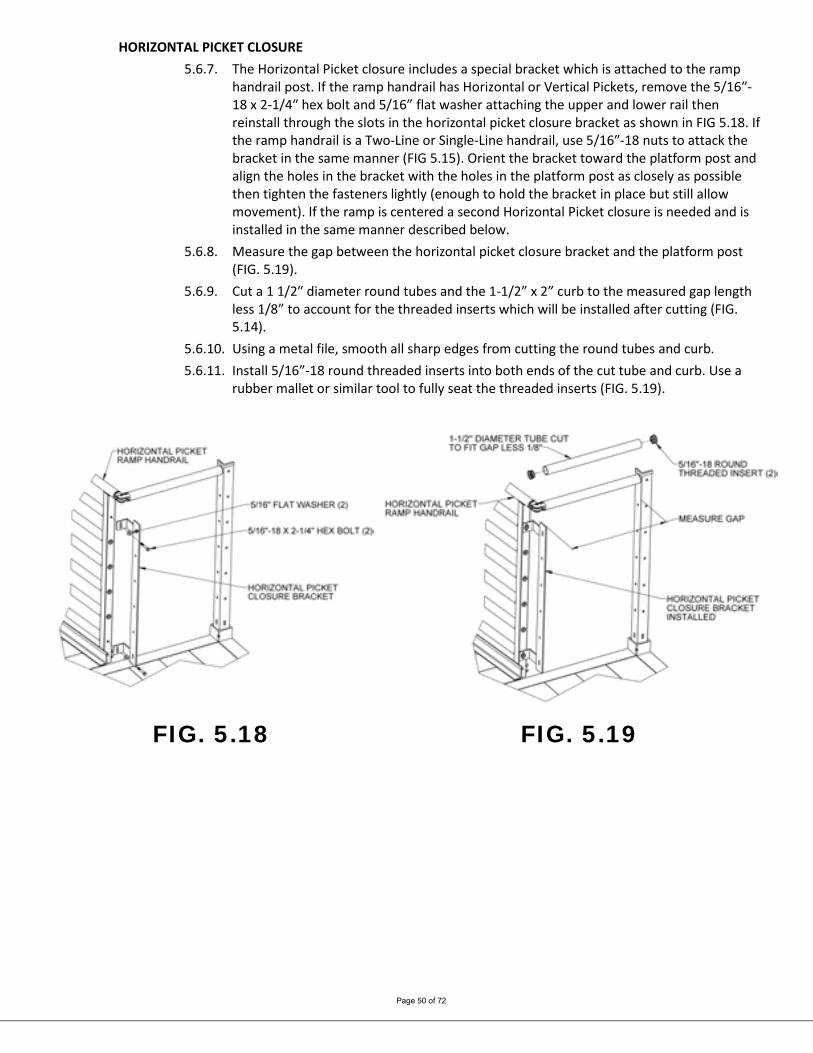
HORIZONTAL PICKET CLOSURE 5.6.7. The Horizontal Picket closure includes a special bracket which is attached to the ramp
handrail post. If the ramp handrail has Horizontal or Vertical Pickets, remove the 5/16″-18 x 2-1/4″ hex bolt and 5/16” flat washer attaching the upper and lower rail then reinstall through the slots in the horizontal picket closure bracket as shown in FIG 5.18. If the ramp handrail is a Two-Line or Single-Line handrail, use 5/16″-18 nuts to attack the bracket in the same manner (FIG 5.15). Orient the bracket toward the platform post and align the holes in the bracket with the holes in the platform post as closely as possible then tighten the fasteners lightly (enough to hold the bracket in place but still allow movement). If the ramp is centered a second Horizontal Picket closure is needed and is installed in the same manner described below.
5.6.8. Measure the gap between the horizontal picket closure bracket and the platform post (FIG. 5.19).
5.6.9. Cut a 1 1/2″ diameter round tubes and the 1-1/2” x 2” curb to the measured gap length less 1/8” to account for the threaded inserts which will be installed after cutting (FIG. 5.14).
5.6.10. Using a metal file, smooth all sharp edges from cutting the round tubes and curb. 5.6.11. Install 5/16”-18 round threaded inserts into both ends of the cut tube and curb. Use a
rubber mallet or similar tool to fully seat the threaded inserts (FIG. 5.19).
FIG. 5.18 FIG. 5.19

Page 51 of 72
5.6.12. Attach the tube with threaded inserts installed to the platform handrail post and the horizontal picket closure bracket using 5/16”-18 x 1” long hex bolts and 5/16” flat washers but do not tighten fully (FIG. 5.20).
5.6.13. Repeat the steps above until all five 1 1/2″ diameter round tubes and curb have been installed then tighten all fasteners securely. For the curb, use the hole which is 1/2” above the lowermost hole in the platform post and horizontal picket closure bracket to align the curb correctly.
FIG. 5.20
Page 52 of 72
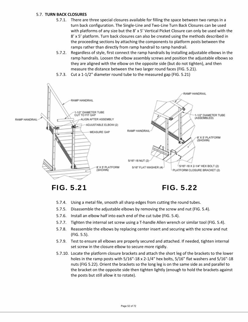
5.7. TURN BACK CLOSURES 5.7.1. There are three special closures available for filling the space between two ramps in a
turn back configuration. The Single-Line and Two-Line Turn Back Closures can be used with platforms of any size but the 8’ x 5’ Vertical Picket Closure can only be used with the 8’ x 5’ platform. Turn back closures can also be created using the methods described in the proceeding sections by attaching the components to platform posts between the ramps rather than directly from ramp handrail to ramp handrail.
5.7.2. Regardless of style, first connect the ramp handrails by installing adjustable elbows in the ramp handrails. Loosen the elbow assembly screws and position the adjustable elbows so they are aligned with the elbow on the opposite side (but do not tighten), and then measure the distance between the two larger round faces (FIG. 5.21).
5.7.3. Cut a 1-1/2″ diameter round tube to the measured gap (FIG. 5.21)
FIG. 5.21 FIG. 5.22
5.7.4. Using a metal file, smooth all sharp edges from cutting the round tubes. 5.7.5. Disassemble the adjustable elbows by removing the screw and nut (FIG. 5.4). 5.7.6. Install an elbow half into each end of the cut tube (FIG. 5.4). 5.7.7. Tighten the internal set screw using a T-handle Allen wrench or similar tool (FIG. 5.4). 5.7.8. Reassemble the elbows by replacing center insert and securing with the screw and nut
(FIG. 5.5). 5.7.9. Test to ensure all elbows are properly secured and attached. If needed, tighten internal
set screw in the closure elbow to secure more rigidly. 5.7.10. Locate the platform closure brackets and attach the short leg of the brackets to the lower
holes in the ramp posts with 5/16″-18 x 2-1/4″ hex bolts, 5/16” flat washers and 5/16″-18 nuts (FIG 5.22). Orient the brackets so the long leg is on the same side as and parallel to the bracket on the opposite side then tighten lightly (enough to hold the brackets against the posts but still allow it to rotate).
Page 53 of 72
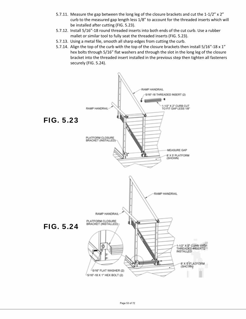
5.7.11. Measure the gap between the long leg of the closure brackets and cut the 1-1/2” x 2” curb to the measured gap length less 1/8” to account for the threaded inserts which will be installed after cutting (FIG. 5.23).
5.7.12. Install 5/16”-18 round threaded inserts into both ends of the cut curb. Use a rubber mallet or similar tool to fully seat the threaded inserts (FIG. 5.23).
5.7.13. Using a metal file, smooth all sharp edges from cutting the curb. 5.7.14. Align the top of the curb with the top of the closure brackets then install 5/16″-18 x 1″
hex bolts through 5/16” flat washers and through the slot in the long leg of the closure bracket into the threaded insert installed in the previous step then tighten all fasteners securely (FIG. 5.24).
FIG. 5.23
FIG. 5.24

Page 54 of 72
5.7.15. If installing a Single-Line Turn Back Closure the installation is complete. 5.7.16. If installing a Two-Line Turn Back Closure, a second 1-1/2″ diameter round tube is
installed in the second hole from the top of the ramp handrail posts in the same manner as the curb at the bottom. The only difference is the platform closure brackets are secured by installing the 5/16″-18 x 2-1/4″ hex bolts into the threaded inserts in the lower ramp handrail rather than using a nut (FIG. 5.25).
FIG. 5.25
FIG. 5.26
5.7.17. The 8’ x 5’ Vertical Picket Closure can only be used with the 8’ x 5’ platform. If the ramps
have Vertical Picket or Horizontal Picket handrails, first remove the 5/16″-18 x 2-1/4″ hex bolts and 5/16” flat washers from the uppermost rail and reinstall through the slots in the 8’ x 5’ Vertical Picket Closure brackets (FIG. 5.26). If the ramps have Single-Line or Two-Line handrails, use the included 5/16″-18 x 2-1/4″ hex bolts and 5/16” flat washers with 5/16″-18 nuts inserted through the slots in the 8’ x 5’ Vertical Picket Closure brackets and the uppermost hole in the ramp handrail post in a similar manner to FIG 5.22.
5.7.18. Attach the base of the 8’ x 5’ Vertical Picket Closure to the platform side rail using four 1/4″ x 1” long self-drilling screws (FIG. 5.26).

Page 55 of 72
6. FINAL PLATFORM/RAMP STEPS AND CHECKS 6.1. SECURE RAMPS TO PLATFORMS
6.1.1. Once positioning of all ramps and platforms, and installation of all handrails, connectors, and end loops are complete, you will need to secure ramps to platforms with Ramp End Clips (included in PRHP - RAMP HANGER PAIR).
Use two Ramp End Clips at all locations where ramps meet platforms. 6.1.2. Position each Ramp End Clip with the hole pointing up and oriented as shown (FIG. 6.1),
then insert the short end of the Ramp End Clip into small gap between the ramp and the platform in the area where the ramp side rail overlaps the ramp end tread (FIG. 6.1).
6.1.3. Before the Ramp End Clip contacts the ramp side rail, rotate the Ramp End Clip so the short end extends into the recess under the ramp end tread. (FIG. 6.1).
6.1.4. Use the hole in the Ramp End Clip as a template to drill 1/8” pilot hole in the platform side rail, then use the 1/4” x 1” long self-drilling screws to secure the Ramp End Clip to the platform side rail (FIG. 6.2)
6.1.5. FIG. 6.3 shows the top view of the completed process.
FIG. 6.1
FIG. 6.2 FIG. 6.3

Page 56 of 72
INSTALL RAMP HANDRAIL END LOOPS 6.1.6. The PATHWAY 3G Modular Ramp System may include both upper and lower end loops
(FIG. 6.4). Upper and lower end loops are installed in the same manner. If the end loop being installed doesn’t fit correctly (i.e. the connector plate is angled the wrong direction, the lower leg seems too long or short), you are most likely trying to install it on the wrong end of the ramp or ramp run.
6.1.6.1. Install the o-ring over the swaged portion of the end loop until it rests against the loop shoulder (FIG. 6.5).
FIG. 6.4
FIG. 6.5
Page 57 of 72
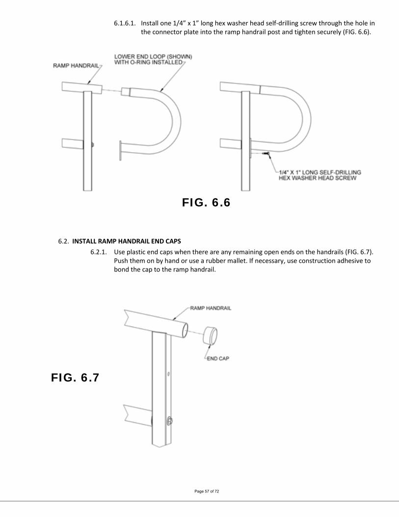
6.1.6.1. Install one 1/4” x 1” long hex washer head self-drilling screw through the hole in the connector plate into the ramp handrail post and tighten securely (FIG. 6.6).
FIG. 6.6
6.2. INSTALL RAMP HANDRAIL END CAPS
6.2.1. Use plastic end caps when there are any remaining open ends on the handrails (FIG. 6.7). Push them on by hand or use a rubber mallet. If necessary, use construction adhesive to bond the cap to the ramp handrail.
FIG. 6.7
Page 58 of 72
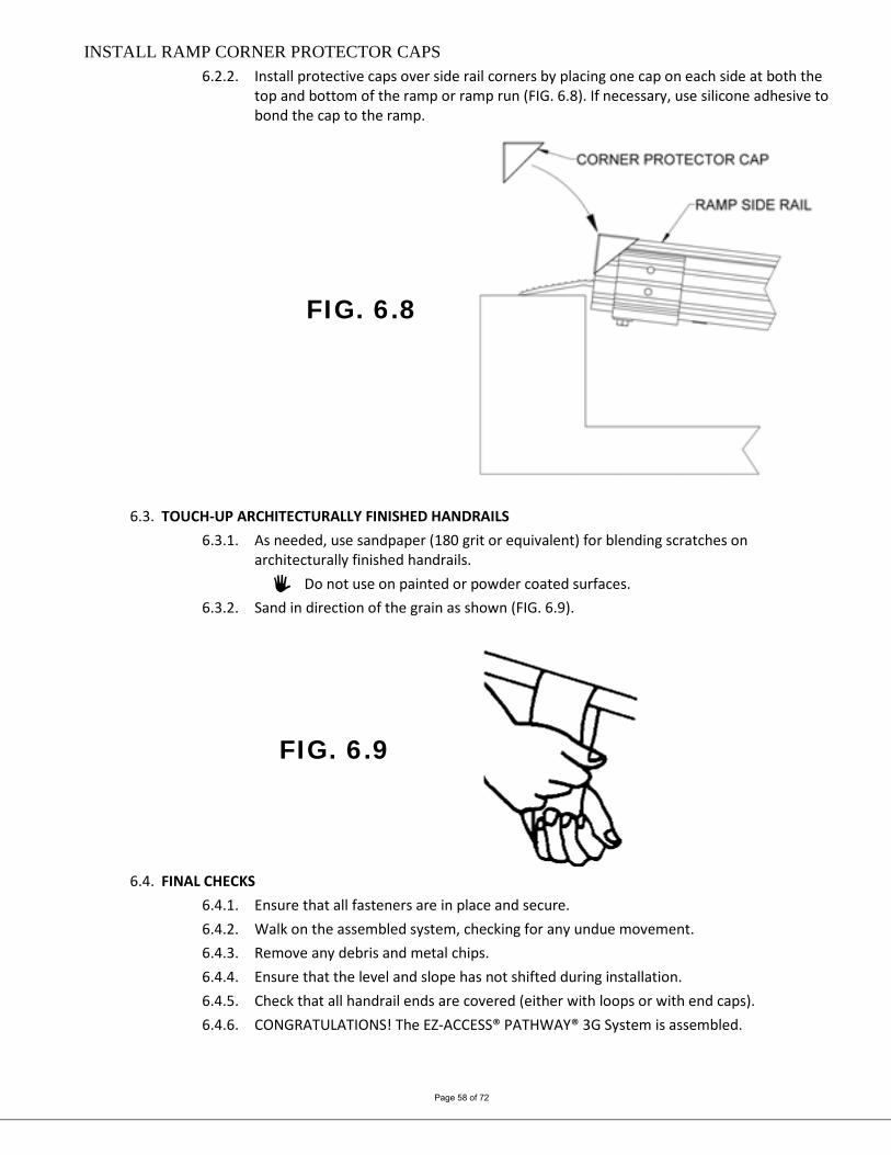
INSTALL RAMP CORNER PROTECTOR CAPS 6.2.2. Install protective caps over side rail corners by placing one cap on each side at both the
top and bottom of the ramp or ramp run (FIG. 6.8). If necessary, use silicone adhesive to bond the cap to the ramp.
FIG. 6.8
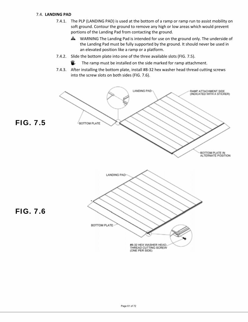
6.3. TOUCH-UP ARCHITECTURALLY FINISHED HANDRAILS 6.3.1. As needed, use sandpaper (180 grit or equivalent) for blending scratches on
architecturally finished handrails. Do not use on painted or powder coated surfaces.
6.3.2. Sand in direction of the grain as shown (FIG. 6.9).
FIG. 6.9
6.4. FINAL CHECKS
6.4.1. Ensure that all fasteners are in place and secure. 6.4.2. Walk on the assembled system, checking for any undue movement. 6.4.3. Remove any debris and metal chips. 6.4.4. Ensure that the level and slope has not shifted during installation. 6.4.5. Check that all handrail ends are covered (either with loops or with end caps). 6.4.6. CONGRATULATIONS! The EZ-ACCESS® PATHWAY® 3G System is assembled.

Page 59 of 72
7. OPTIONAL EQUIPMENT 7.1. RAMP SUPPORT TOP
The PRST (RAMP SUPPORT TOP) provides supplemental support at the upper (or lower) end of the ramp. When used, the support top replaces the PRHBPR (RAMP HANDRAIL END BRACKET PAIR).
7.1.1. Attach top support brackets with two 5/16"-18 x 1-1/2" hex bolts and each 5/16" flat washers (FIG. 7.1).
There is a “left” and “right” top support bracket but they can be installed on either side of the ramp depending on whether they are used at the upper or lower end of the ramp or ramp run. The two longer studs must be oriented toward the end of the ramp regardless of the side where they are being installed.
7.1.2. If used with a transition plate (upper or lower), the following steps are completed after the ramp is resting on a supporting surface and transition plate is installed.
7.1.3. Locate the appropriate PRLxxPR (RAMP LEG PAIR where xx denotes the leg length) for the location. Insert the leg into a foot. Make sure the leg is fully engaged in the foot and the foot will be oriented so it extends under the ramp once installed (FIG. 7.2). Tighten the thumb screw on each foot securely.
If installing on soft soil it may be necessary to set the foot on a concrete pad. 7.1.4. Place the slot in the ramp leg over the two shorter studs of the top support bracket,
install 5/16”-18 nylon insert locknuts and 5/16” flat washers on each stud adjust height if needed and tighten locknuts. Repeat on the opposite side.
7.1.5. Insert plugs into tops of the ramp legs. 7.1.6. Refer to previous sections for anchoring upper and lower transitions.
FIG. 7.1 FIG. 7.2

Page 60 of 72
7.2. RAMP LOWER TRANSITION 7.2.1. The lower transition, in combination with an PRST (RAMP SUPPORT TOP) is commonly
used to span wider gaps or accommodate larger angular misalignment than can be achieved with an upper transition. It can also be used in place of the ground transition in some situations. Despite being called a lower transition, it can be used at either end of a ramp or ramp run.
The lower transition is the larger of the two transitions. 7.2.2. Lift the end of the ramp and install the lower transition as shown (FIG. 7.3). 7.2.3. If the lower transition is resting on the ground, anchoring is optional. 7.2.4. If a lower transition is resting on any type of raised area (i.e., a platform, deck or porch),
it must be anchored using the same procedures as used in ‘ANCHOR RAMP UPPER TRANSITION.’
FIG. 7.3
7.3. SINGLE BRIDGE PLATE 7.3.1. Securing to WOODEN SURFACE OR PLATFORM:
7.3.1.1. To secure to a wooden deck or platform, use the four supplied 1/4″ x 1″ self-drilling self-tapping screws.
7.3.2. Securing to CONCRETE OR ASPHALT: 7.3.2.1. To secure to concrete or asphalt, drill a 1/4″ diameter hole at least 1 1/4″
deep. Ensure that all debris from the hole is removed using a shop vacuum, blower or other suitable type of equipment.
7.3.2.2. Insert the four supplied pin head mushroom anchors and secure by using a hammer to drive the pin in flush with the mushroom.
Use PBPxx (BRIDGE PLATE) in the horizontal (flat) position only. It is intended to be used to bridge gaps up to a maximum of 6” between a platform and a porch
or deck. IT IS NOT INTENDED TO BE USED AS A RAMP OR ON AN INCLINE. Ensure that at least 1” on each of the supporting edges of the plate is supported on a good,
sound construction surface that is free from defects (FIG 7.4).
FIG. 7.4
Page 61 of 72
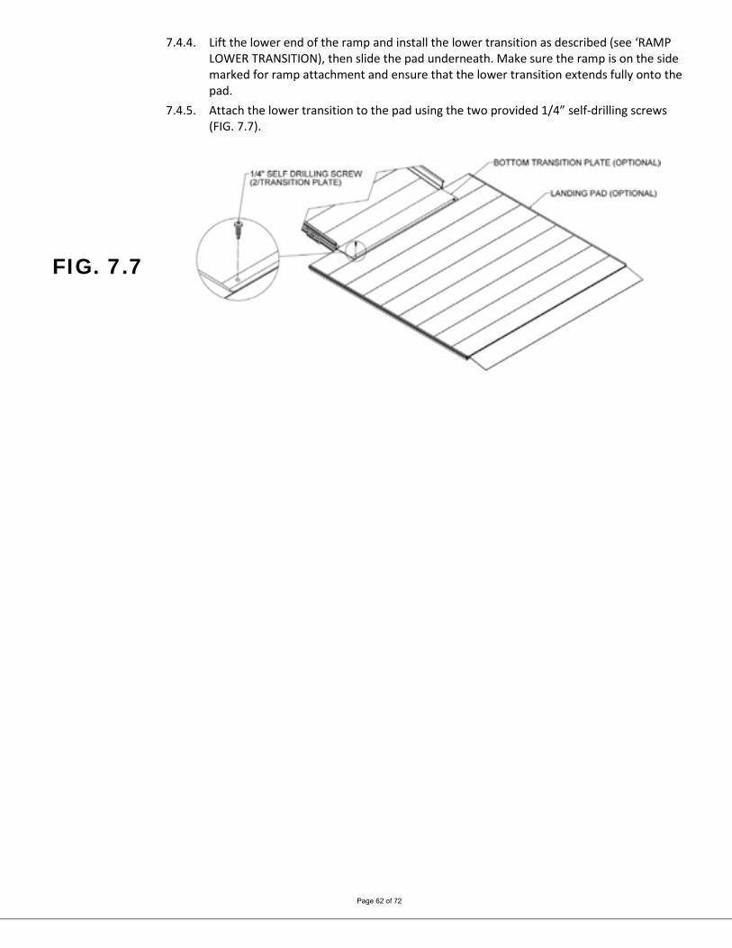
7.4. LANDING PAD 7.4.1. The PLP (LANDING PAD) is used at the bottom of a ramp or ramp run to assist mobility on
soft ground. Contour the ground to remove any high or low areas which would prevent portions of the Landing Pad from contacting the ground.
WARNING The Landing Pad is intended for use on the ground only. The underside of the Landing Pad must be fully supported by the ground. It should never be used in an elevated position like a ramp or a platform.
7.4.2. Slide the bottom plate into one of the three available slots (FIG. 7.5). The ramp must be installed on the side marked for ramp attachment.
7.4.3. After installing the bottom plate, install #8-32 hex washer head thread cutting screws into the screw slots on both sides (FIG. 7.6).
FIG. 7.5
FIG. 7.6
Page 62 of 72
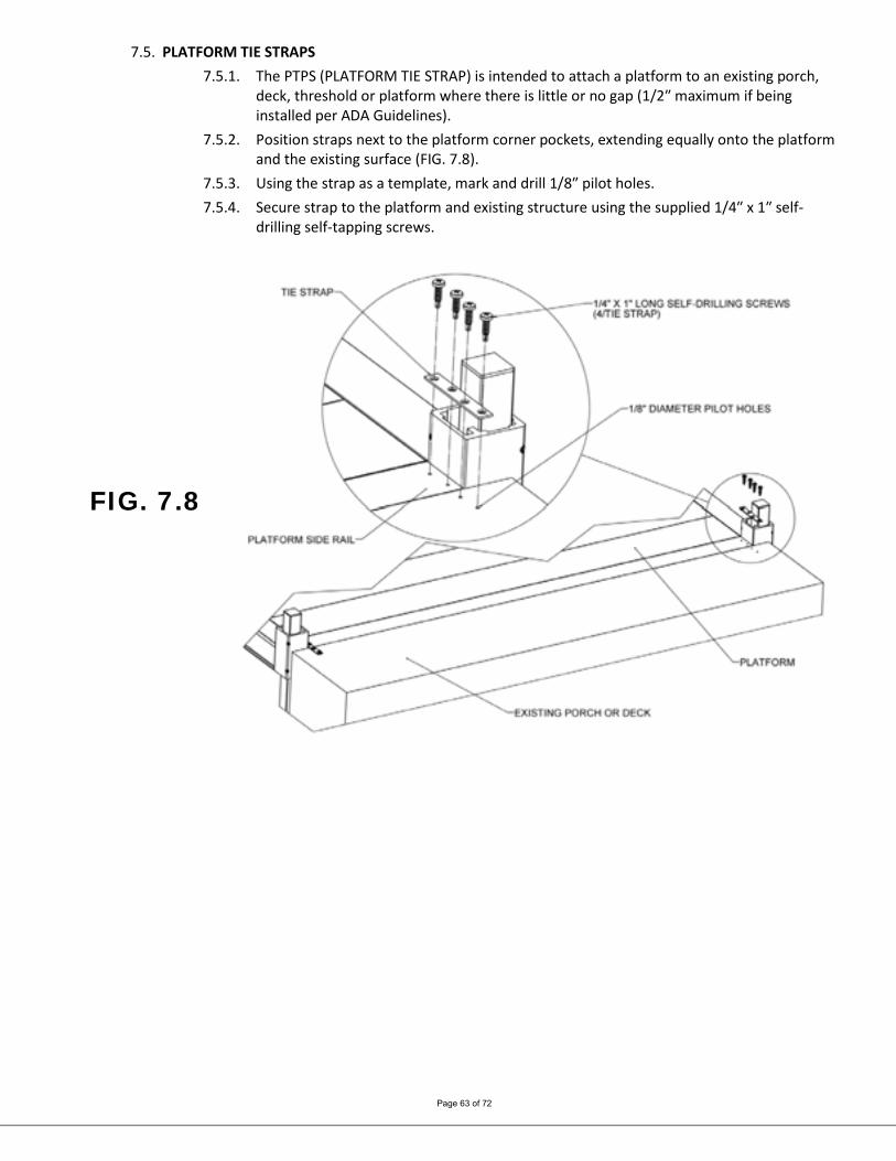
7.4.4. Lift the lower end of the ramp and install the lower transition as described (see ‘RAMP LOWER TRANSITION), then slide the pad underneath. Make sure the ramp is on the side marked for ramp attachment and ensure that the lower transition extends fully onto the pad.
7.4.5. Attach the lower transition to the pad using the two provided 1/4” self-drilling screws (FIG. 7.7).
FIG. 7.7
Page 63 of 72
7.5. PLATFORM TIE STRAPS 7.5.1. The PTPS (PLATFORM TIE STRAP) is intended to attach a platform to an existing porch,
deck, threshold or platform where there is little or no gap (1/2″ maximum if being installed per ADA Guidelines).
7.5.2. Position straps next to the platform corner pockets, extending equally onto the platform and the existing surface (FIG. 7.8).
7.5.3. Using the strap as a template, mark and drill 1/8″ pilot holes. 7.5.4. Secure strap to the platform and existing structure using the supplied 1/4″ x 1″ self-
drilling self-tapping screws.
FIG. 7.8
Page 64 of 72
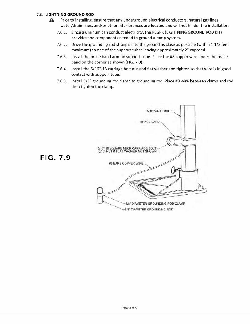
7.6. LIGHTNING GROUND ROD Prior to installing, ensure that any underground electrical conductors, natural gas lines,
water/drain lines, and/or other interferences are located and will not hinder the installation. 7.6.1. Since aluminum can conduct electricity, the PLGRK (LIGHTNING GROUND ROD KIT)
provides the components needed to ground a ramp system. 7.6.2. Drive the grounding rod straight into the ground as close as possible (within 1 1/2 feet
maximum) to one of the support tubes leaving approximately 2" exposed. 7.6.3. Install the brace band around support tube. Place the #8 copper wire under the brace
band on the corner as shown (FIG. 7.9). 7.6.4. Install the 5/16″-18 carriage bolt nut and flat washer and tighten so that wire is in good
contact with support tube. 7.6.5. Install 5/8″ grounding rod clamp to grounding rod. Place #8 wire between clamp and rod
then tighten the clamp.
FIG. 7.9
Page 65 of 72
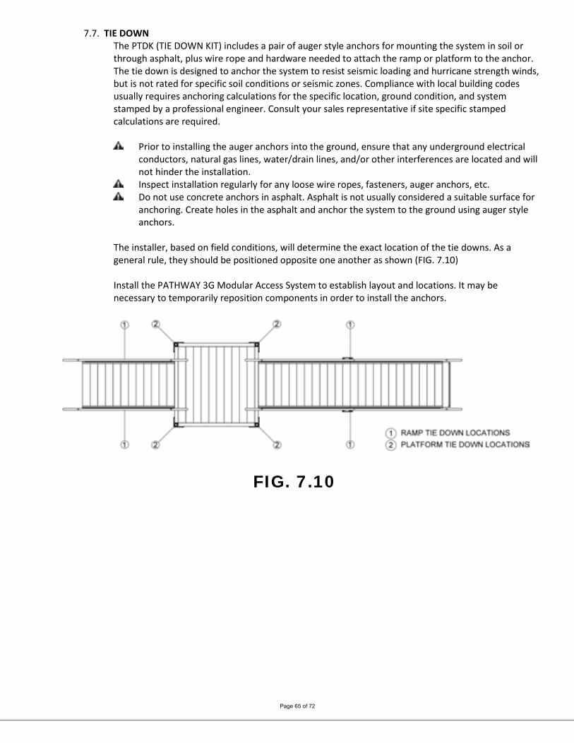
7.7. TIE DOWN The PTDK (TIE DOWN KIT) includes a pair of auger style anchors for mounting the system in soil or through asphalt, plus wire rope and hardware needed to attach the ramp or platform to the anchor. The tie down is designed to anchor the system to resist seismic loading and hurricane strength winds, but is not rated for specific soil conditions or seismic zones. Compliance with local building codes usually requires anchoring calculations for the specific location, ground condition, and system stamped by a professional engineer. Consult your sales representative if site specific stamped calculations are required.
Prior to installing the auger anchors into the ground, ensure that any underground electrical conductors, natural gas lines, water/drain lines, and/or other interferences are located and will not hinder the installation.
Inspect installation regularly for any loose wire ropes, fasteners, auger anchors, etc. Do not use concrete anchors in asphalt. Asphalt is not usually considered a suitable surface for
anchoring. Create holes in the asphalt and anchor the system to the ground using auger style anchors.
The installer, based on field conditions, will determine the exact location of the tie downs. As a general rule, they should be positioned opposite one another as shown (FIG. 7.10) Install the PATHWAY 3G Modular Access System to establish layout and locations. It may be necessary to temporarily reposition components in order to install the anchors.
FIG. 7.10

Page 66 of 72
FIG. 7.11
7.7.1. For platforms, install one tie down at each corner where a support tube is installed (FIG 7.11).
7.7.2. Place a brace band around the support tube approximately 2″ below either the corner pocket of a platform and secure using the 5/16″ square neck carriage bolt 5/16″ nut, and 3/8″ washer.
7.7.3. Place one end of the wire rope between the legs of the brace band and around the square neck carriage bolt then secure the wire rope together using the supplied 3/16″ wire rope clamp.
7.7.4. If using the auger style tie downs (soil and asphalt), install the auger into the ground in line with the brace band. Install as close to vertical as possible, 10° angle maximum. Use a 1/2″ steel rod (or similar item) through the eye of the auger anchor to turn the auger anchor into the ground. Keep turning the auger until only the eye is exposed.
7.7.5. If using concrete anchors, install per the manufacturer's instructions then install a 5/16″ eyebolt.
7.7.6. Place the other end of the wire rope either through the eye of the auger anchor or through the eyebolt in the concrete anchor and secure the wire rope together using the supplied 3/16″ wire rope clamps.
Make sure that the wire rope has been pulled taut and all slack has been removed prior to securing it with the wire rope clamps.
7.7.7. Cut the excess wire rope as required using a cable cutter or other appropriate tool. Wrap the cut ends with vinyl tape (or equivalent) to keep the wire rope from fraying.
7.7.8. Repeat for all support tubes. 7.7.9. If used on a single ramp, install tie downs approximately in the center using eyebolts (FIG.
7.10). 7.7.10. If there is are support tubes in the ramp run, the same method as described above for
platforms can be used. Otherwise, drill a 5/16″ hole below the tread surface (approximately 3/4″ above the bottom of the side rail) and between the ribs underneath the treads in each of the side rails at the desired location.
Page 67 of 72
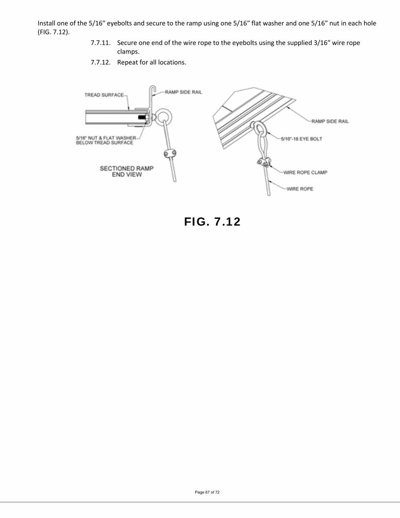
Install one of the 5/16″ eyebolts and secure to the ramp using one 5/16″ flat washer and one 5/16″ nut in each hole (FIG. 7.12).
7.7.11. Secure one end of the wire rope to the eyebolts using the supplied 3/16″ wire rope clamps.
7.7.12. Repeat for all locations.
FIG. 7.12
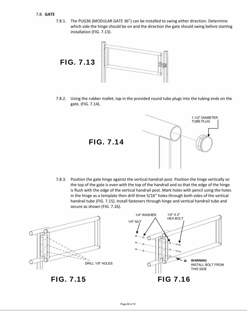
Page 68 of 72
7.8. GATE 7.8.1. The PUG36 (MODULAR GATE 36”) can be installed to swing either direction. Determine
which side the hinge should be on and the direction the gate should swing before starting installation (FIG. 7.13).
FIG. 7.13
7.8.2. Using the rubber mallet, tap in the provided round tube plugs into the tubing ends on the
gate. (FIG. 7.14).
FIG. 7.14
7.8.3. Position the gate hinge against the vertical handrail post. Position the hinge vertically so the top of the gate is even with the top of the handrail and so that the edge of the hinge is flush with the edge of the vertical handrail post. Mark holes with pencil using the holes in the hinge as a template then drill three 5/16″ holes through both sides of the vertical handrail tube (FIG. 7.15). Install fasteners through hinge and vertical handrail tube and secure as shown (FIG. 7.16).
FIG. 7.15 FIG 7.16
WARNING INSTALL BOLT FROM THIS SIDE
DRILL 1/8″ HOLES
1/4″ NUT
1/4″ WASHER
1/4″ X 2″ HEX BOLT
1-1/2″ DIAMETER TUBE PLUG

Page 69 of 72
7.8.4. Remove gravity latch and finger catch from bag. IMPORTANT! Discard the screws included in the same bag as the gravity latch
and finger catch, as they will not be used. Instead, use the screws included in the separate hardware bag for the following steps.
7.8.5. Center finger catch on the gate square tube opposite the hinge and mark center of holes with a pencil. Drill three 1/8″ holes through one side of the vertical handrail tube (FIG. 7.17).
7.8.6. Use 1/4" nut driver to secure catch with screws (FIG. 7.18).
FIG. 7.17 FIG. 7.18
7.8.7. Clip the latch to the finger catch and center on the step or ramp vertical square tube. Mark center of the holes with pencil. Drill four 1/8″ holes through one side of the vertical handrail tube (FIG. 7.19).
7.8.8. Use 1/4″ nut driver to secure latch using screws. (FIG. 7.20).
FIG. 7.19 FIG. 7.20
DRILL 5/16″ HOLES
WARNING INSTALL BOLT FROM THIS SIDE
#8 X 1/2″ LONG HEX WASHER HEAD SCREW
CENTER ON POST
#8 X 1/2″ LONG HEX WASHER HEAD SCREW
DRILL 1/8″ HOLES
Page 70 of 72
8. MAINTENANCE & SAFETY 8.1. PERIODIC MAINTENANCE AND SAFETY
8.1.1. Caution should be used at all times. Proper maintenance and upkeep to the ramp surface is vital.
8.1.2. Use ramp only with a qualified helper. 8.1.3. Always use your mobility device’s lap belt. 8.1.4. It is important that you refer to your equipment’s Owner Guide for the proper
degree of incline/decline and chair direction before attempting ramp use. Never exceed its recommendations.
8.1.5. Periodically check the ramp for damage and tighten any loose fasteners to ensure safety.
8.1.6. At all times, keep the ramp clear of dirt, leaves, and other debris that may accumulate on the surface. Simply sweeping the ramp or using a garden hose will usually suffice, but, if needed, a damp cloth or soft brush with soap and water can be used (avoid use of alkaline detergents).
8.1.7. If ramp surface is covered with ice and/or snow, the recommended procedure is to remove ice and/or snow before use. Snow accumulation should be shoveled and the tread surface swept clean. Magnesium Chloride may be used to melt snow or ice accumulation on the ramp; however, after the snow and/or ice threat has cleared, be sure to clean the tread surface with soap and water (avoiding alkaloid detergents) to remove Magnesium Chloride residue. See DE-ICING below for additional information.
8.1.8. Do not play on or near ramp. 8.1.9. Do not use handrails or ramp to support planters, decorations, etc. 8.1.10. RAMP SURFACE MAY BECOME SLIPPERY WHEN WET, USE EXTRA CAUTION WHEN
THE RAMP SURFACE IS WET. 8.1.11. If any part of the ramp is damaged or loose, DO NOT USE UNTIL REPAIRS ARE MADE
BY A CERTIFIED INSTALLER OR OTHER QUALIFIED PERSON.
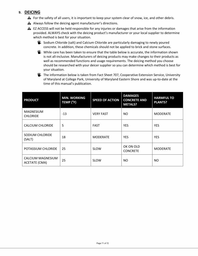
Page 71 of 72
9. DEICING For the safety of all users, it is important to keep your system clear of snow, ice, and other debris. Always follow the deicing agent manufacturer’s directions. EZ ACCESS will not be held responsible for any injuries or damages that arise from the information
provided. ALWAYS check with the deicing product’s manufacturer or your local supplier to determine which method is best for your situation.
Sodium Chloride (salt) and Calcium Chloride are particularly damaging to newly poured concrete. In addition, these chemicals should not be applied to brick and stone surfaces.
While care has been taken to ensure that the table below is accurate, the information shown is not all-inclusive. Manufacturers of deicing products may make changes to their products as well as recommended functions and usage requirements. The deicing method you choose should be researched with your deicer supplier so you can determine which method is best for your situation.
The information below is taken from Fact Sheet 707, Cooperative Extension Service, University of Maryland at College Park, University of Maryland Eastern Shore and was up-to-date at the time of this manual’s publication.
PRODUCT MIN. WORKING TEMP (oF) SPEED OF ACTION
DAMAGES CONCRETE AND METALS?
HARMFUL TO PLANTS?
MAGNESIUM CHLORIDE -13 VERY FAST NO MODERATE
CALCIUM CHLORIDE 5 FAST YES YES
SODIUM CHLORIDE (SALT) 18 MODERATE YES YES
POTASSIUM CHLORIDE 25 SLOW OK ON OLD CONCRETE MODERATE
CALCIUM MAGNESIUM ACETATE (CMA) 25 SLOW NO NO

Page 72 of 72
Thank you for choosing EZ-ACCESS® for your accessibility needs.
We’d love to hear from you! 1-800-451-1903
www.ezaccess.com