Embed Size (px)
Citation preview
IMAGE TO COME
Zimmer® NexGen®
LPS-Flex Mobile and LPS-Mobile Bearing KneesSurgical Technique
United States Version


Zimmer® NexGen® LPS-Flex Mobile and LPS-Mobile Bearing Knees Surgical Technique 1
Table of Contents
Introduction 2
Patient Selection 3
Preoperative Planning 4
Surgical Technique 5
Patient Preparation 5
Incision and Exposure 6
Step One: Resect Proximal Tibia 10
Introduction 10
Extramedullary Technique 10
Option 1: Using the Cut Guide 10
Extramedullary Technique 14
Option 2: Using the Spike Arm 14
Intramedullary Technique 17
Option 1: Using the Cut Guide 17
Intramedullary Technique 21
Option 2: Using the Spike Arm 21
Step Two: Establish Femoral Alignment 24
Step Three: Cut the Distal Femur 26
Step Four: Check Extension Gap 27
Step Five: Size Femur and Establish External Rotation 28
Step Six: Finish the Femur 29
Option 1: Posterior Referencing Technique 29
Option 2: Anterior Referencing Technique 32
Step Seven: Check Flexion Gap 34
Balance Flexion/Extension Gaps 34
Step Eight: Patellar Preparation 35
Step Nine: Finish the Tibia 35
Option 1: Using the NexGen Fluted Stem Mobile Tibial Component 35
Option 2: Using the NexGen MIS LPS-Mobile Tibial Component 38
Step Ten: Trial Reduction 42
Step Eleven: Implantation 42
Option 1: Using the NexGen Fluted Stem Mobile Tibial Component 42
Option 2: Using the NexGen MIS LPS-Mobile Tibial Component 43
Closure 45
Rehabilitation Protocol 45
Appendix A: NexGen Flexion Balancing Instruments 46
Zimmer NexGen LPS-Flex Mobile and LPS-Mobile Bearing Knees Surgical Technique

Zimmer® NexGen® LPS-Flex Mobile and LPS-Mobile Bearing Knees Surgical Technique2
Fig. 1 Contact area at 155°
Introduction
Successful total knee arthroplasty depends in part on re-establishment of normal lower extremity alignment, proper implant design and orientation, secure implant fixation, adequate soft tissue balancing and stability.
The LPS-Flex Mobile and LPS-Mobile Bearing Knees are posterior stabilized prostheses designed to accommodate greater range of motion for appropriate patients, such as those who are physically capable or whose cultural customs or recreational/work activities require deep flexion.
The development of the LPS-Mobile Bearing Knee Systems is the result of an analysis of a knee prosthesis as it undergoes deep flexion beyond 120˚. For example, the interaction of the posterior condyles on the articular surface was carefully studied. As a result, efforts have been made to optimize the contact area as the posterior condyles roll back to flexion angles up to 155˚ (Fig. 1). This is addressed by thickening the posterior condyles, thereby extending the radius.
The tibial articular surface was also considered in the design. In deep flexion, the extensor mechanism experiences a high level of stress as the soft tissues are stretched and pulled tightly against the anterior tibia and distal femur. The LPS-Mobile Bearing Knee Systems are designed to help relieve these stresses through a larger, deeper anterior cutout on the articular surface (Fig. 2). This cutout accommodates the extensor mechanism in deep flexion.
(Reference page 29 “Option 1 – Posterior Referencing Technique” and page 32 “Option 2 – Anterior Referencing Technique”)
There Are Two Possible Surgical Techniques
1. Multi-Reference® 4-in-1 Instruments Multi-Reference 4-in-1 Instruments are designed to help the surgeon accomplish the goals of total knee arthroplasty by combining optimal alignment accuracy with a simple, straight-forward technique. The instruments promote accurate cuts to help ensure secure component fixation.
The Multi-Reference 4-in-1 Instruments provide a choice of either anterior or posterior referencing techniques for making the femoral finishing cuts. The anterior referencing technique uses the anterior cortex to set the A/P position of the femoral component. The posterior condyle cut is variable. The posterior referencing technique uses the posterior condyles to set the A/P position of the femoral component. The variable cut is made anteriorly. The posterior referencing technique will help provide a consistent flexion gap. Femoral rotation is determined using the posterior condyles or epicondylar axis as a reference.
The instruments and technique assist the surgeon in restoring the center of the hip, knee, and ankle to lie on a straight line, establishing a neutral mechanical axis. The femoral and tibial components are oriented perpendicular to this axis (Fig. 3). Use the template overlay (available through your Zimmer representative) to help determine the angle between the anatomic axis and the mechanical axis of the femur. This angle should be reproduced intraoperatively.
Additionally, the cam/spine mechanism has been modified to provide greater jump height as the knee prosthesis undergoes deep flexion between 120˚ and 155˚. The cam/spine mechanism induces mechanical rollback while inhibiting posterior subluxation of the tibia.
These design features accommodate high-flexion activities and, together with proper patient selection, surgical technique, and rehabilitation, increase the potential for greater range of motion. The LPS-Flex Mobile and LPS-Mobile Bearing Knee Components can be implanted using any of the NexGen® Knee Instrument Systems.
The surgical approach to the LPS-Mobile Knee is the same as for a fixed bearing knee. Intraoperatively, the only variation is the tibial preparation. The decision of fixed or mobile can be made intraoperatively.
When implanting the LPS-Flex Mobile femoral component, the gold Femoral Finishing Guide is used. When implanting the LPS ‘non-Flex’ femoral component, the (silver colored) MIS Femoral Finishing Guide is used.
Fig. 2
2. Flexion Balancing Instruments Will Be Addressed in Appendix A (Page 46)

Zimmer® NexGen® LPS-Flex Mobile and LPS-Mobile Bearing Knees Surgical Technique 3
Fig. 4 Thigh-calf angle
Meets selection criteria <90˚
>90˚
6°
Transverse Axis
Mec
hani
cal A
xis
90°Fig. 3
Patient SelectionA common view among orthopaedic surgeons is that certain patients have greater potential for achieving higher flexion after knee replacement. Patients with good flexion preoperatively tend to get better motion postoperatively. To optimize use of the high-flexion design elements of the LPS-Flex Mobile Bearing Knee, the following criteria should be considered:
• The patient should have a need and desire to perform deep- flexion activities. This need may be dictated by cultural or social customs where practices such as frequent kneeling, sitting “cross- legged,” and squatting are common. Also, activities specific to daily living, leisure and recreation, or job performance may require high-flexion capability.
• The patient should be capable of reaching 110° of flexion preoperatively with a reasonable probability of achieving a range of 125° postoperatively.
• It may also be important to consider the length of time the patient has not performed high- flexion activities.
• The patient should have a thigh- calf index of less than 90° (Fig. 4).
• The patient should have stable and functional collateral ligaments.
• If the patient has an angular deformity, it should be less than 20°. Keep in mind that it is more difficult to achieve ligament balance in these patients. And, in patients with severe deformity, consider the patient expectation for achieving high flexion.
The LPS-Flex Mobile Bearing Knee is designed to accommodate high flexion, and not create high flexion.
If using a minimally invasive technique, it is suggested that the patient criteria include non-obese patients with preoperative flexion greater than 90°. Patients with varus or valgus deformities greater than 15° are typically candidates for a standard arthrotomy technique.
Patients with severe deformity or instability may not be suitable candidates for a mobile bearing implant.
See the back section of the surgical technique for package insert.

Zimmer® NexGen® LPS-Flex Mobile and LPS-Mobile Bearing Knees Surgical Technique4
Preoperative Conditioning
To prepare the patient for surgery, it may be helpful for the patient to perform mobility exercises to prepare the ligaments and muscles for the postoperative rehabilitation protocol.
Preoperative Planning
Multi-Reference 4-in-1 Instrumenation and Flexion Balancing Instrumentation This surgical technique helps the surgeon ensure that the distal femur will be cut perpendicular to the mechanical axis and, after soft tissue balancing, will be parallel to the resected surface of the proximal tibia.
Use the various templates to approximate the appropriate component sizes. The final sizes will be determined intraoperatively; therefore, larger and smaller sizes should be available during surgery. Plan appropriately to have a fixed bearing system available if a femoral/tibial mismatch exists.
Verify that the femoral and tibial component sizes approximated will be compatible by cross-referencing the femoral and tibial sizes on the Interchangeability Chart.
Note: If a femoral/tibial mismatch exists, a fixed bearing system should be used.
Femoral Size
1
AB C D E F G
AB/1-3
2
3
4
5
6
7
8
AB/1-3
AB/1-3
C/2-4
C/2-4
C/2-4
D/3-5
D/3-5
D/3-5
E/4-6
E/4-6
E/4-6
F/5-7
F/5-7
F/5-7
G/6-8
G/6-8
G/6-8Tibi
al S
ize
Patella Size Use standard size Patellas with all LPS and LPS-Flex Femoral Components 26mm (inset only)† 32mm† 38mm29mm† 35mm 41mm
† For G & H Femoral Components, the 26, 29 and 32mm patellar components must be inset.* For matching purposes, if the tibial component has a (+) size, ignore the (+) symbol.

Zimmer® NexGen® LPS-Flex Mobile and LPS-Mobile Bearing Knees Surgical Technique 5
Surgical Technique
Surgical technique is an important factor to consider when attempting to maximize range of motion in total knee arthroplasty (TKA). Close attention must be paid to balancing the flexion and extension gaps, clearing posterior osteophytes, releasing the posterior capsule, and reproducing the joint line.
Although the joint line often changes as a result of a posterior cruciate substituting procedure, it is important that an attempt be made to maintain the joint line when high flexion is a priority. Depending on the degree, altering the joint line can cause patellofemoral issues and limit the degree of flexion. An elevated joint, for example, can cause tibiofemoral tightness in roll-back and thus restrict flexion.1
When using the gap technique, it is possible that the joint line may be moved proximally, especially if there is a preoperative flexion contracture or if the selected femoral component is smaller than the A/P dimension of the femur. The alteration of the joint line can be minimized by accurately measuring for the femoral component size and performing a posterior capsulotomy to correct flexion contractures.
Patient PreparationTo prepare the limb for total knee arthroplasty, adequate muscle relaxation is required. This will facilitate the eversion of the patella, if desired, and minimize tension in the remaining quadriceps below the level of the tourniquet. It is imperative that the muscle relaxant be injected prior to inflation of the tourniquet. Alternatively, spinal or epidural anesthesia should produce adequate muscle relaxation.
If using a tourniquet, apply the proximal thigh tourniquet and inflate it with the knee in hyperflexion to maximize that portion of the quadriceps that is below the level of the tourniquet. This will help minimize restriction of the quadriceps and ease patellar eversion.
Once the patient is draped and prepped on the operating table, determine the landmarks for the surgical incision with the leg in extension.

Zimmer® NexGen® LPS-Flex Mobile and LPS-Mobile Bearing Knees Surgical Technique6
Incision and Exposure The incision may be made with the leg in extension or flexion depending on surgeon preference. The surgeon can choose a midvastus approach, a subvas-tus approach, or a medial parapatellar arthrotomy. Also, depending on surgeon preference, the patella can be either everted or subluxed.The length of the incision is dependent on the size of the femoral component needed. Although the goal of a minimally invasive technique is to complete the surgery with an approximately 10cm-14cm incision, it may be necessary to extend the incision if visualization is inadequate. If the incision must be extended, it is advisable to extend it gradually and only to the degree necessary.
Make a slightly oblique parapatellar skin incision, beginning approximately 2cm proximal and medial to the superior pole of the patella, and extend it approximately 10cm to the level of the superior patellar tendon insertion at the center of the tibial tubercle (Fig. 5). Be careful to avoid disruption of the tendon insertion. This will facilitate access to the vastus medialis obliquus, and allow a minimal split of the muscle. It will also improve visualization of the lateral aspect of the joint obliquely. The length of the incision should be about 50% above and 50% below the joint line. If the length of the incision is not distributed evenly relative to the joint line, it is preferable that the greater portion be distal.
Divide the subcutaneous tissue to the level of the retinaculum.
Fig. 5
MIS Midvastus Approach Make a medial parapatellar incision into the capsule, preserving approximately 1cm of peritenon and capsule medial to the patellar tendon. This is important to facilitate complete capsular closure. Split the superficial enveloping fascia of the quadriceps muscle percutaneously in a proximal direction over a length of approximately 6cm. This will mobilize the quadriceps and allow for significantly greater lateral translation of the muscle while minimizing tension on the patellar tendon insertion.
Split the vastus medialis obliquus approximately 1.5cm-2cm (Fig. 6).
Fig. 6

Zimmer® NexGen® LPS-Flex Mobile and LPS-Mobile Bearing Knees Surgical Technique 7
MIS Subvastus ApproachBecoming accustomed to operating through a small incision and adopting the concept of a mobile window may be facilitated by starting with a shortened medial parapatellar arthrotomy. This will help to improve visualization of the anatomy during the initial stages of becoming familiar with an MIS approach.
When comfortable with the MIS medial parapatellar approach, performing the arthrotomy through a midvastus approach will help preserve the quadriceps tendon and a portion of the medial muscular attachment. As this procedure becomes more familiar, the level of the midvastus incision should be lowered to maintain more muscle attachment.
The subvastus arthrotomy provides excellent exposure through an MIS incision. The oblique portion of the incision starts below the vastus medialis obliquus (VMO) attachment and will preserve all the medial muscle attachments, including the retinacular attachment to the medial patella. A key aspect of the subvastus approach is that it is not necessary to evert the patella. This helps avoid tearing of the muscle fibers and helps maintain muscle contraction soon after surgery.
The longitudinal incision should extend only to the point of insertion of the VMO inferiorly, not to the proximal pole. Begin the arthrotomy at the medial edge of the tubercle and extend it along the border of the retinaculum/tendon to a point on the patella corresponding to 10 o’clock on a left knee or 2 o’clock on a right knee. Then continue the incision obliquely 1cm-2cm just below and in line with the VMO fibers (Fig. 7). Do not extend the oblique incision beyond this point as it creates further muscle invasion without providing additional exposure.
Perform a medial release according to surgeon judgment, depending on the degree of varus or valgus deformity. To facilitate a medial release, place the knee in extension with a rake retractor positioned medially to provide tension that will assist in developing this plane. For valgus deformities, consider performing a more conservative medial release to avoid over-releasing an already attenuated tissue complex.
With the knee in extension and a rake retractor positioned to place tension on the patella, remove the retropatellar fat pad. Then excise a small piece of the capsule at the junction of the longitudinal and oblique retinacular incisions. This release allows the patella to retract laterally. Undermine the suprapatellar fat pad, but do not excise it. This helps ensure that the Femoral A/P Measuring Guide will be placed directly on bone rather than inadvertently referencing off soft tissue, which may increase the femoral size measurement.
Fig. 7
Use blunt dissection to undermine the skin incision approximately 1cm-2cm around the patella.
Slightly flex the knee and remove the deep third of the fat pad. The patella can be either everted or subluxed. If everting the patella, release the lateral patellofemoral ligament to facilitate full eversion and lateral translation of the patella. Then use hand-held three-pronged or two-pronged hooks to begin to gently evert the patella. Be careful to avoid disrupting the extensor insertion. To help evert the patella, slowly flex the joint and externally rotate the tibia while applying gentle pressure. Once the patella is everted, use a standard-size Hohmann retractor or two small Hohmann retractors along the lateral flare of the tibial metaphysis to maintain the eversion of the patella and the extensor mechanism.
Note: It is imperative to maintain close observation of the patellar tendon throughout the procedure to ensure that tension on the tendon is minimized, especially if everting the patella and when positioning the patient.
Remove any large patellar osteophytes.
Release the anterior cruciate ligament, if present. Perform a subperiosteal dissection along the proximal medial and lateral tibia to the level of the tibial tendon insertion. Then perform a limited release of the lateral capsule (less than 5mm) to help minimize tension on the extensor mechanism.

Zimmer® NexGen® LPS-Flex Mobile and LPS-Mobile Bearing Knees Surgical Technique8
Placement of a lateral retractor is very important for adequate retraction of the patella. With the knee extended, slip the retractor into the lateral gutter and lever it against the retinaculum at the superomedial border of the patella. As the knee is flexed, the patella is retracted laterally to provide good visualization of the joint.
MIS Medial Parapatellar Arthrotomy Minimally invasive total knee arthroplasty can be performed with a limited medial parapatellar arthrotomy. Begin by making a 10cm-14cm midline skin incision from the superior aspect of the tibial tubercle to the superior border of the patella. Following subcutaneous dissection, develop medial and lateral flaps, and dissect proximally and distally to expose the extensor mechanism. This permits mobilization of the skin and subcutaneous tissue as needed during the procedure. In addition, with the knee in flexion, the incision will stretch 2cm-4cm due to the elasticity of the skin, allowing broader exposure.
The goal of minimally invasive surgery is to limit the surgical dissection without compromising the procedure. The medial parapatellar arthrotomy is used to expose the joint, but the proximal division of the quadriceps tendon should be limited to a length that permits only lateral subluxation of the patella without eversion (Fig. 8). Incise the quadriceps tendon for a length of 2cm-4cm initially. If there is difficulty displacing the patella laterally or if the patellar tendon is at risk of tearing, extend the arthrotomy proximally along the quadriceps tendon until adequate exposure is achieved.
Fig. 8
PCL ResectionRemoving the PCL will make it easier to balance the collateral ligaments. Because the LPS-Flex Mobile Bearing Knee Prosthesis is a posterior cruciate ligament substituting design, it is necessary to completely resect the PCL. Any residual stump of the PCL may impinge in the cam/spine mechanism causing pain and limited motion. Resection of the PCL may influence the height of the flexion and extension gaps. Check for symmetry and balance of the flexion and extension gaps. Any differences in the gaps must be addressed.

Zimmer® NexGen® LPS-Flex Mobile and LPS-Mobile Bearing Knees Surgical Technique 9
Fig. 9
Lax Tensed
L M L M
Contracture
Caution: Do not release the popliteal tendon, as this may cause instability.
Varus Release To correct most fixed varus deformities (Fig. 9), progressively release the tight medial structures until they reach the length of the lateral supporting structures. The extent of the release can be monitored by inserting laminar spreaders within the femorotibial joint and judging alignment with a plumb line. To facilitate the release, excise osteophytes from the medial femur and tibia. These osteophytes tent the medial capsule and ligamentous structures, and their removal can produce a minimal correction before beginning the soft tissue release. Posteromedial osteophytes may need to be removed after the proximal tibia is resected.
Soft Tissue ReleasesThe objective of this procedure should be to distribute contact stresses across the artificial joint as symmetrically as possible.2
Soft tissue balancing is vital to help assure implant stability. The basic principle for ligament release entails that the tight contracted concave side is lengthened to match the convex side. The goal is to maintain a consistent and rectangular, not rhomboidal flexion and extension gap.
With the Flexion Balancing Instruments, the flexion gap is addressed first (Reference Appendix A, page 39). In flexion the medial and lateral soft tissues as well as the posterior joint capsule are easily accessible for releases. This procedure helps minimize the need for releases in extension and avoids over-releasing the flexion gap.
After accessing the knee joint, balancing of the soft tissue structures and removal of osteophytes is initiated. Posteromedial osteophytes may need to be removed after the proximal tibia is resected.

Zimmer® NexGen® LPS-Flex Mobile and LPS-Mobile Bearing Knees Surgical Technique10
With the knee in extension, elevate a subperiosteal sleeve of soft tissue from the proximal medial tibia, including the deep medial collateral ligament, superficial medial collateral ligament, and insertion of the pes anserinus tendons. Continue the elevation with a periosteal elevator to free the posterior fibers. To improve exposure during the release, retract this subperiosteal sleeve using a Homan retractor.
Release the insertion of the semimembranosus muscle from the posteromedial tibia, and concurrently remove posterior osteophytes.
Continue the release distally on the anteromedial surface of the tibia for 8cm-10cm and strip the periosteum medially from the tibia. This should be sufficient for moderate deformities. For more severe deformities, continue subperiosteal stripping posteriorly and distally.
When varus malalignment is present with a flexion contracture, it may be necessary to release or transversely divide the posterior capsule
Valgus ReleaseApproach the valgus knee (Fig. 10) in a similar fashion to that described for the varus knee; however, to provide better visualization, the bone cuts are usually made before the ligament release.
Fig. 10
Lax Tensed
L M L M
Contracture
By comparison with that of a varus release, the principle of a valgus release is to elongate the contracted lateral structures to the length of the medial structures. Though lateral osteophytes may be present and should be removed, they do not bowstring the lateral collateral ligament in the same way as osteophytes on the medial side.
This is because the distal insertion of the lateral collateral ligament into the fibular head brings the ligament away from the tibial rim.
For a valgus release, a “piecrust” technique may be preferable. This technique allows lengthening of the lateral side while preserving a continuous soft tissue sleeve, as well as, preserving the popliteus tendon, which ensures stability in flexion.
With the knee in extension and distracted with a laminar spreader, use a 15 blade to transversely cut the arcuate ligament at the joint line. Be careful not to cut or detach the popliteus tendon. Then use the 15 blade to pierce the iliotibial band and the lateral retinaculum in a “piecrust” fashion, both proximally above the joint and distally within the joint. Following the multiple punctures, use a laminar spreader to stretch the lateral side. This should elongate the lateral side and create a rectangular extension space. Use spacer blocks to confirm ligament balance in flexion and extension
For more severe valgus deformities, strip the lateral femoral condyle of its soft-tissue attachments proximally for about 9cm, and then divide the periosteum, the iliotibial tract, and the lateral intramuscular septum transversely from inside out. Be sure that any part of the lateral intramuscular septum that remains attached to the distal femur is free to slide.
Step OneResect Proximal Tibia
IntroductionThe Extramedullary/Intramedullary Tibial Resector provides a choice of techniques for tibial resection. Each of the techniques offers a number of options to accommodate various anatomical conditions and surgeon preferences. To facilitate the handling of bone defects in the proximal tibia, both the extramedullary and if preferred the distal femur may be resected first. See page 24.
Extramedullary TechniqueOption 1: Using the Cut Guide
Step OneAssemble Alignment GuideSlide the Ankle Clamp onto the dovetail at the bottom of the Distal Telescoping Rod. Turn the knob opposite the dovetail to temporarily hold the clamp in place (Fig. 11a). The mediolateral positionof the rod can be adjusted by loosen-ing this knob. When the final position is determined, the knob can be fully tightened to secure it in place.
The system includes a 7-degree Cut Guide.
Fig. 11a

Zimmer® NexGen® LPS-Flex Mobile and LPS-Mobile Bearing Knees Surgical Technique 11
Place the Cut Guide onto the dovetail of the proximal portion of the Cut Guide Telescoping Rod. Tighten the knob to secure the position (Fig. 11b). Arrows are etched onto both the Cut Guide Telescoping Rod and the Distal Telescoping Rod to indicate the correct orientation during assembly (Fig. 11c). Insert the Cut Guide Telescoping Rod into the Distal Telescoping Rod.
Fig. 11b
Fig. 11c
Step TwoPosition Alignment GuideTo improve the exposure of the tibial surface, use the Tibial Retractor to lever the tibia anteriorly. This instrument should be carefully positioned against the posterior cortex of the tibia subperiosteally to prevent neurovascular injury. Use the Patellar Retractor to retract the patella laterally. Adjust the telescoping rod to the approximate length of the tibia and turn the knob on the shaft of the rod to temporarily maintain the length. Place the spring arms of the Ankle Clamp around the ankle proximal to the malleoli (Fig. 12a) and loosen the knob that provides mediolateral adjustment at the ankle.
Fig. 12a
Position the Cut Guide at the proximal tibia. Loosen the knob in the middle of the telescoping rod and adjust the length of the rod until the Cut Guide is proximal to the tibial tubercle. Align the rod with the medial third of the tibial tubercle (Fig. 12b) or just medial to the tubercle.
Adjust the slide at the foot of the rodmediolaterally so the guide is aligned with the mechanical axis of the tibia (Fig. 12c). The longitudinal axis of the rod will usually lie just medial to the mid-point of the tibial tubercle and be centered in line with the intercondylar eminence. The foot of the rod should be positioned about 5mm-10mm medial to the midpoint between the palpable medial and lateral malleoli. The tip should point to the second toe. When the proper mediolateral position is achieved, tighten the knob to secure the Ankle Clamp to the rod. The posterior cortex of the tibia can also be used as a rotational check. In the sagittal plane, align the rod so it is parallel to the anterior tibial shaft by using the slide adjustment at the distal end of the rod. Tighten the knob for the adjustment. If there is a bulky bandage around the ankle, adjust the rod to accommodate the bandage. This will help ensure that the tibia will be cut with the proper slope.
Fig. 12b
Fig. 12c

Zimmer® NexGen® LPS-Flex Mobile and LPS-Mobile Bearing Knees Surgical Technique12
Step ThreeSet Resection LevelEach tip of the Tibial Depth Resection Stylus indicates a different depth. The 2mm tip is used to check the depth from the defective tibial condyle for a minimal cut. The 10mm tip is used to check the depth from the least involved tibialcondyle for an anatomic cut. Insert the Tibial Depth Resection Stylus into thetop of the Cut Guide, using the hole that corresponds to the defective tibial condyle (Fig. 13a).
The stylus will snap into the hole (Figs. 13b & 13c). Confirm that it is fully seated and properly oriented. The 2mm tip should rest on the tibial condyle (Fig. 13d). This positions the slot of theCut Guide to remove 2mm of bone below the tip of the stylus.
Fig. 13b
Fig. 13c
Fig. 13d
Alternatively, rest the 10mm tip of the stylus on the cartilage of the least involved condyle (Fig. 13e).
This will allow the removal of the same amount of bone that the thinnest tibial component would replace.
These two points of resection will usually not coincide. The surgeon must determine the appropriate level of resection based on patient age, bone quality, and the type of prosthetic fixation planned.
Adjust the Cut Guide to the desired depth by adjusting the length of the alignment guide assembly. Then retighten the telescoping rod, and insert a 48mm Headless Screw Pin or 75mm Headless Holding Pin into the hole marked “0” on the lateral side first of the Cut Guide.
Fig. 13a
Fig. 13e

Zimmer® NexGen® LPS-Flex Mobile and LPS-Mobile Bearing Knees Surgical Technique 13
To confirm alignment, insert the Extramedullary Alignment Arch into the Cut Guide and insert the Alignment Rod with Coupler through the arch, passing it distally toward the ankle (Fig.13f).The distal end of the rod should point to the second toe.
Fig. 13f
Insert a second 75mm Headless Holding Pin into the other hole marked “0” (Fig. 13g).
Fig. 13g
Step FourResect the Proximal TibiaLoosen the knob that has secured the Cut Guide onto the Cut Guide Telescop-ing Rod and remove the entire assembly, leaving the Cut Guide in place on the bone. The entire assembly can be left in place for additional fixation during resection.
Additional 2mm adjustments may be made by using the sets of holes marked -2, +2, and +4. The markings on the Cut Guide indicate, in millimeters, the amount of bone resection each will yield relative to the standard tibial resection set by the Cut Guide and Tibial Depth Resection Stylus. Once the tibial resection has been determined, use the Hex-head Holding Pins, 48mm Headed Screw Pins, or Silver Spring Pins to further stabilize the guide. Use a .050-inch oscillating saw blade through the slot on the Cut Guide to cut the proximal surface of the tibia flat (Fig. 14a). Then remove the Cut Guide.
Fig. 14a
Optional TechniqueIf desired, the cut can be made from the top surface of the Cut Guide. The top surface of the guide is 4mm above the slot (Fig. 14b), so the position of the guide must be adjusted to account for this difference. The adjustment can be made after the alignment guide assembly is removed by lifting the Cut Guide off the headless pins, which were inserted through the holes marked “0,” and reinserting the guide through the holes marked “+4” (Fig. 14c).
Fig. 14b
Fig. 14c

Zimmer® NexGen® LPS-Flex Mobile and LPS-Mobile Bearing Knees Surgical Technique14
Extramedullary Technique Option 2: Using the Spike Arm
Step OneAssemble Alignment GuideSlide the Ankle Clamp onto the dovetail at the bottom of the Distal Telescoping Rod. Turn the knob opposite the dovetail to temporarily hold the clamp in place (Fig. 15a). The mediolateral positionof the rod can be adjusted by loosening this knob. When the final position is determined, the knob can be fully tightened to secure it in place.
Fig. 15a
Slide the Spike Arm onto the dovetail at the top of the Spike Arm Telescoping Rod and temporarily secure it by turning the knob at the top of the rod (Fig. 15b).
Fig. 15b
The system includes a 7-degree Cut Guide in left and right configurations.
Lower the adjustment knob in the middle of the Spike Arm Telescoping Rod to the bottom of the threaded portion. Insert the Cut Guide over the threaded portion of the rod above the adjustment knob and slide it all the way up on the dovetail (Fig. 15c). To hold the Cut Guide in place, advance the adjustment knob to the upper end of its range of travel. This will allow for space adjustment after the alignment guide assembly has been secured in position.
Fig. 15c
Arrows are etched onto both the Spike Arm Telescoping Rod and the Distal Telescoping Rod to indicate the correct orientation during assembly (Fig. 15d). Insert the Spike Arm Telescoping Rod into the Distal Telescoping Rod.
Fig. 15d
Step TwoPosition Alignment GuideTo improve exposure of the tibial surface, use the Tibial Retractor to lever the tibia anteriorly. This instrument should be carefully positioned against the posterior cortex of the tibia subperiosteally to prevent neurovascular injury. Use the Patella Retractor to retract the patella laterally.
Adjust the telescoping rod to the approximate length of the tibia and turn the knob on the shaft to temporarily maintain the length.
Place the spring arms of the Ankle Clamp around the ankle proximal to the malleoli (Fig. 16a) and loosen the knob that provides mediolateral adjustment at the ankle.
Fig. 16a
Position the Cut Guide at the proximal tibia. Loosen the knob in the middle of the telescoping rod and adjust the length of the rod until the long spike on the Spike Arm just contacts the tibial plateau. The Cut Guide should be proximal to the tibial tubercle. Center the long spike mediolaterally on the bone surface anterior to the tibial spine. This should align the rod with the medial third of the tibial tubercle. Stabilize the Alignment Guide by tapping the Spike Arm until only the long spike engages the tibial plateau. Do not drive the long spike in too far (Fig. 16b).

Zimmer® NexGen® LPS-Flex Mobile and LPS-Mobile Bearing Knees Surgical Technique 15
Fig. 16b
Adjust the slide at the foot of the rod mediolaterally so the guide is aligned with the mechanical axis of the tibia. The longitudinal axis of the rod will usually lie just medial to the mid-point of the tibial tubercle and be centered over the intercondylar eminence. The foot of the rod should be positioned about 5mm-10mm medial to the midpoint between the palpable medial and lateral malleoli. The tip should point to the second toe. When the proper mediolateral position is achieved, tighten the knob to secure the Ankle Clamp to the rod.
In the sagittal plane, align the rod so it is parallel to the anterior tibial shaft by using the slide adjustments at both the proximal and distal ends of the rod (Fig. 16c). Then tighten the knobs for both adjustments. If there is a bulky bandage around the ankle, adjust the rod to accommodate the bandage. This will help ensure that the tibia will be cut with the proper slope.
Set the final position of the extramedullary alignment guide assembly by tapping the Spike Arm until both the long and short spikes are fully impacted in the proximal tibia (Fig. 16d). Then tighten the knob in the middle of the telescoping rod assembly.
Fig. 16c
Fig. 16d
Step Three Set Resection LevelEach tip of the Tibial Depth Resection Stylus indicates a different depth. The 2mm tip is used to check the depth from the defective tibial condyle for a minimal cut. The 10mm tip is used to check the depth from the least involved tibialcondyle for an anatomic cut. Insert the Tibial Depth Resection Stylus into thetop of the Cut Guide, using the hole that corresponds to the defective tibial condyle (Fig. 17a).
Fig. 17a
The stylus will snap into the hole (Figs. 17b & 17c). Confirm that it is fully seated and properly oriented. The 2mm tip should rest on the tibial condyle (Fig. 17d). This positions the slot of theCut Guide to remove 2mm of bone below the tip of the stylus.
Fig. 17b
Fig. 17c
Fig. 17d

Zimmer® NexGen® LPS-Flex Mobile and LPS-Mobile Bearing Knees Surgical Technique16
Pin 1 Pin 3
Pin 2
Alternatively, rest the 10mm tip of the stylus on the cartilage of the least involved condyle (Fig. 17e).
Fig. 17e
This will allow the removal of the same amount of bone that the thinnest tibial component would replace.
These two points of resection will usually not coincide. The surgeon must determine the appropriate level of resection based on patient age, bone quality, and the type of prosthetic fixation planned.
Adjust the Cut Guide to the desired depth by turning the adjustment knob. Then insert a 75mm Headless Holding Pin or a 48mm Headless Screw Pin into the hole marked “0” on the lateral side of the guide (Fig. 17f).
Fig. 17f
To confirm alignment, insert the Extramedullary Alignment Arch onto the Cut Guide and insert the Alignment Rod with Coupler through the arch, passing it distally toward the ankle. The distal end of the rod should point to the secondtoe (Fig. 17g).
Fig. 17g
Insert a second 75mm Headless Holding Pin into the medial hole marked “0.” Once the tibial resection has been determined, use the Hexhead Holding Pins, or 48mm Headed Screw Pins, or Silver Spring Pins to further stabilize the guide.
The extramedullary alignment arch can be left attached to the tibial cut guide for added stability. A 0.050” reciprocating saw blade can be used to make the medial and lateral tibial plateau cuts. Then remove the alignment tower to finish the tibial cuts.
Step FourResect the Proximal TibiaLoosen the adjustment knob below the Cut Guide until the knob is at the bottom of the threaded portion of the rod. Then loosen the knob on the telescoping rod. Use a slaphammer to disengage the spikes on the Spike Arm. Raise the telescoping rod until the dovetail disengages the Cut Guide. Then open the arms of the Ankle Clamp and remove the entire assembly, leaving the Cut Guide in place on the bone.
If desired, the Alignment Arch and Alignment Rod with Coupler can be used on the Cut Guide again to check alignment.
2mm adjustments may be made by using the sets of holes marked -2, +2, and +4. The markings on the Cut Guide indicate, in millimeters, the amount of bone resection each will yield relative to the standard tibial resection set by the Cut Guide and Tibial Depth Resection Stylus.
Use a .005-inch oscillating saw blade through the slot on the Cut Guide to cut the proximal surface of the tibia flat (Fig. 18a). Then remove the Cut Guide.
Fig. 18a

Zimmer® NexGen® LPS-Flex Mobile and LPS-Mobile Bearing Knees Surgical Technique 17
2mm
Optional TechniqueIf desired, the cut can be made from the top surface of the Cut Guide. The top surface of the guide is 4mm above the slot (Fig. 18b), so the position of the guide must be adjusted to account for this difference. The adjustment can be made when the Cut Guide is first positioned by using the etch lines, which are in 2mm increments, at the top of the Spike Arm Telescoping Rod (Fig. 18c).
Fig. 18b
Fig. 18c
Alternatively, the adjustment can be made after the alignment guide assembly is removed by lifting the Cut Guide off the headless pins, which were inserted through the holes marked “0,” and reinserting the guide through the holes marked “+4” (Fig. 18d).
Intramedullary TechniqueOption 1: Using the Cut Guide
To improve exposure of the tibial surface, use the Tibial Retractor to lever the tibia anteriorly. This instrument should be carefully positioned against the posterior cortex of the tibia subperiosteally to prevent neurovascular injury. Use the Patella Retractor to retract the patella laterally.
A preoperative radiograph of the tibia is necessary to make sure that the tibial shaft is straight and will accept the Tibial IM Rod. Some tibias are bowed or have too small a canal and will not accept the rod. The acetate template used for femoral planning can be inverted and used on the tibia.
Step OnePosition IM Alignment GuideUse the Universal Handle to start a hole in the proximal tibia just anterior to the anterior cruciate ligament insertion and centered mediolaterally (Fig. 19a). This may seem too far anterior; however, it is the straight proximal extension of the tibial medullary canal. If a hole is started further posteriorly, excessive posteriorslope may be cut into the proximal tibia.
Fig. 18d
Fig. 19a

Zimmer® NexGen® LPS-Flex Mobile and LPS-Mobile Bearing Knees Surgical Technique18
Drill a hole using the 8mm IM Drill. Suction the canal to remove medullary contents.
Slowly insert the Tibial IM Rod (00-5977-044-00) into the canal. The flutes on the rod will aid decompression of the canal during insertion.
Attach the 7-degree Revision Tibial Boom (00-5787-010-00) to the rod (Fig. 19b). This boom is needed to provide the appropriate cut for the posterior slope of the tibial plate.
Fig. 19b
Lower the adjustment knob on the IM Alignment Guide to the bottom of the threaded portion. Insert the 0-degree Cut Guide over the threaded portion of the alignment guide above the adjustment knob and slide it up until it just engages the dovetail (Fig. 19c). This will allow forfinal adjustment after the alignment guide has been secured in position. To hold the Cut Guide in place, advance the adjustment knob until it contacts the underside of the guide.
Fig. 19c
Only the 0-degree Cut Guide will fit onto the IM Alignment Guide. The 7-degree Cut Guide will not fit onto the IM Alignment Guide. Using the 0-degree Cut Guide with the 7-degree RevisionTibial Boom will give you a 7-degree cut.
Slide the barrel of the IM Alignment Guide onto the boom, making sure that the locking knob has been adjusted to allow free access (Fig. 19d). Rotate the boom on the rod until the Cut Guide isproperly positioned mediolaterally on the anterior tibia. Use the medial third of the tibial tubercle as a landmark. Then slightly secure the knob on the boom.
Fig. 19d

Zimmer® NexGen® LPS-Flex Mobile and LPS-Mobile Bearing Knees Surgical Technique 19
To determine varus/valgus alignment, insert the Extramedullary Alignment Arch onto the Cut Guide and insert the Align-ment Rod with Coupler through the arch, passing it distally toward the ankle (Fig. 19e). The distal end of the rod should point to the second toe.
Fig. 19e
If the surgeon would like to set the Cut Guide at a 90-degree angle to the Tibial IM Rod, tighten the knob at the top of the IM Alignment Guide clockwise in the “90°” direction as etched on top of the knob (Fig. 19f). Do not overtighten the knob.
If the alignment check suggests a varus/valgus adjustment, rotate the barrel of the IM Alignment Guide on the boom to align the Alignment Rod to the second toe. When the appropriate varus/valgus alignment is achieved, tighten the knob at the top of the IM Alignment Guide counterclockwise in the “Var-Valg” direction as etched on top of the knob (Fig. 19g). This will hold the varus/valgus position of the Cut Guide. Do not overtighten the knob.
Fig. 19g
Step TwoSet Resection LevelEach tip of the Tibial Depth Resection Stylus indicates a different depth. The 2mm tip is used to check the depth from the defective tibial condyle for a minimal cut. The 10mm tip is used to check the depth from the least involved tibialcondyle for an anatomic cut. Insert the Tibial Depth Resection Stylus into thetop of the Cut Guide, using the hole that corresponds to the defective tibial condyle (Fig. 20a). The stylus will snap into the hole (Figs. 20b & 20c). Confirm that it is fully seated and properly oriented. The 2mm tip should rest on the tibial condyle (Fig. 20d). This positions the slot of the Cut Guide to remove 2mm of bone below the tip of the stylus.
Fig. 20a
Fig. 20b
Fig. 20c
Fig. 19f

Zimmer® NexGen® LPS-Flex Mobile and LPS-Mobile Bearing Knees Surgical Technique20
Fig. 20d
Alternatively, rest the 10mm tip of the stylus on the cartilage of the least involved condyle (Fig. 20e). This will allow the removal of the same amount of bone that the thinnest tibial component would replace.
Fig. 20e
These two points of resection will usually not coincide. The surgeon must determine the appropriate resection based on patient age, bone quality, and the type of prosthetic fixation planned.
Adjust the Cut Guide to the desired depth by turning the adjustment knob. Then insert 48mm Headless Pin, or 75mm Headless Holding Pins into the holes marked “0” lateral side first (Fig. 20f).
Step ThreeResect the Proximal TibiaLoosen the adjustment knob below the Cut Guide until the knob is at the bottom of the threaded portion of the rod. Loosen the varus/valgus adjustment knob on the IM Alignment Guide. Use a slaphammer to raise the IM Rod until the dovetail portion of the IM Alignment Guide disengages from the Cut Guide. Remove the alignment assembly, leaving the Cut Guide in place on the bone.
If desired, the Alignment Arch and Alignment Rod with Coupler can be used on the Cut Guide again to check alignment.
Additional 2mm adjustments may be made by using the sets of holes marked -2, +2, and +4. The markings on the Cut Guide indicate, in millimeters, the amount of bone resection each will yield relative to the standard tibial resection set by the Cut Guide and Tibial Depth Resection Stylus. Once the tibial resection has been determined, use the Hex-head Holding Pins, 48mm Headed Screw Pins, or Silver Spring Pins to further stabilize the guide.
Use a .050-inch oscillating saw blade through the slot on the Cut Guide to cut the proximal surface of the tibia flat (Fig. 21a). Then remove the Cut Guide.
Fig. 21a
Fig. 20f

Zimmer® NexGen® LPS-Flex Mobile and LPS-Mobile Bearing Knees Surgical Technique 21
2mm
Optional TechniqueIf desired, the cut can be made from the top surface of the Cut Guide. The top surface of the guide is 4mm above the slot (Fig. 21b), so the position of the guide must be adjusted to account for this difference. The adjustment can be made when the Cut Guide is first positioned by using the etch lines, which are in 2mm increments, on the IM Alignment Guide (Fig. 21c).
Fig. 21b
Fig. 21c
Alternatively, the adjustment can be made after the IM Alignment Guide is removed by lifting the Cut Guide off the headless pins, which were insertedthrough the holes marked “0,” and reinserting the guide through the holes marked “+4” (Fig. 21d).
Intramedullary TechniqueOption 2: Using the Spike Arm
To improve exposure of the tibial surface, use the Tibial Retractor to lever the tibia anteriorly. This instrument should be carefully positioned against the posterior cortex of the tibia subperiosteally to prevent neurovascular injury. Use the Patella Retractor to retract the patella laterally.
A preoperative radiograph of the tibia is necessary to make sure that the tibial shaft is straight and will accept the Tibial IM Rod. Some tibias are bowed or have too small a canal and will not accept the rod. The acetate template used for femoral planning can be inverted and used on the tibia.
Step OneInsert IM RodUse the Universal Handle to start a hole in the proximal tibia just anterior to the anterior cruciate ligament insertion and centered mediolaterally (Fig. 22a). This may seem too far anterior; however, it is the straight proximal extension of the tibial medullary canal. If a hole is started further posteriorly, excessive posteriorslope may be cut into the proximal tibia.Drill a hole using the 8mm IM Drill. Suction the canal to remove medullary contents. Slowly insert the Tibial IM Rod (00-5977-044-00) into the canal. The flutes on the rod will aid decompression of the canal during insertion.
Fig. 22a
Fig. 21d

Zimmer® NexGen® LPS-Flex Mobile and LPS-Mobile Bearing Knees Surgical Technique22
Step TwoPosition Cut GuideThe system includes a 7-degree Cut Guide in left and right configurations.
Slide the Spike Arm onto the top of the Spike Arm Telescoping Rod and secure it temporarily by turning the knob at the top of the rod (Fig. 23a).
Fig. 23a
Lower the adjustment knob in the middle of the Spike Arm Telescoping Rod to the bottom of the threaded portion. Insert the Cut Guide over the threaded portion of the rod above the adjustment knob and slide it all the way up on the dovetail(Fig. 23b). To hold the Cut Guide in place, advance the adjustment knob to the end of its range of travel. This will allow for final adjustment after the alignment assembly has been secured in position.
Slide the Spike Arm assembly over the IM Rod (Figs. 23c, 23d & 23e). Lower the assembly until the long spike engages the tibial surface. Adjust the assembly to the correct rotation. Impact the Spike Arm until both the long and short spikes are fully engaged in bone. Loosen the knob at the top of the Spike Arm Telescoping Rod, and slide the rod and Cut Guide toward the anterior tibialsurface. Then tighten the knob.
Fig. 23b
Fig. 23c
Fig. 23d
Fig. 23e
To confirm alignment, insert the Extramedullary Alignment Arch onto the Cut Guide and insert the Alignment Rod with Coupler through the arch, passing it distally toward the ankle. The distal end of the rod should point to the second toe.

Zimmer® NexGen® LPS-Flex Mobile and LPS-Mobile Bearing Knees Surgical Technique 23
Step ThreeSet Resection LevelEach tip of the Tibial Depth Resection Stylus indicates a different depth. The 2mm tip is used to check the depth from the defective tibial condyle for a minimal cut. The 10mm tip is used to check the depth from the least involved tibial condyle for an anatomic cut.
Insert the Tibial Depth Resection Stylus into the top of the Cut Guide, using the hole that corresponds to the defective tibial condyle (Fig. 24a). The stylus will snap into the hole (Figs. 24b & 24c). Confirm that it is fully seated and properly oriented. The 2mm tip should rest on the tibial condyle (Fig. 24d). This positions the slot of the Cut Guide to remove 2mm of bone below the tip of the stylus.
Fig. 24a
Fig. 24b
Fig. 24c
Fig. 24d
Alternatively, rest the 10mm tip of the stylus on the cartilage of the least involved condyle (Fig. 24e). This will allow the removal of the same amount of bone that the thinnest tibial componentwould replace.
Fig. 24e
These two points of resection will usually not coincide. The surgeon must determine the appropriate resection based on patient age, bone quality, and the type of prosthetic fixation planned.
Adjust the Cut Guide to the desired depth by turning the adjustment knob. Then insert 48mm Headless Screw Pins or 75mm Headless Holding Pins into the holes marked “0” lateral side first.
Step FourResect the Proximal TibiaLoosen the adjustment knob below the Cut Guide until the knob is at the bottom of the threaded portion of the rod. Use a slaphammer to raise the IM Rod and Spike Arm assembly until the dovetail portion of the IM Alignment Guide disengages from the Cut Guide. Remove the alignment assembly, leaving the Cut Guide in place on the bone.
If desired, the Alignment Arch and Alignment Rod with Coupler can be used on the Cut Guide again to check alignment.
Additional 2mm adjustments may be made by using the sets of holes marked -2, +2, and +4. The markings on the Cut Guide indicate, in millimeters, the amount of bone resection each will yield relative to the standard tibial resection set by the Cut Guide and Tibial Depth Resection Stylus. Once the tibial resection has been determined, use the Hex-head Holding Pins, Silver Spring Pins, or 48mm Headed Screw Pins to further stabilize the guide.
Use a .050-inch oscillating saw blade through the slot on the Cut Guide to cut the proximal surface of the tibia flat (Fig. 25a). Then remove the Cut Guide.
Fig. 25a

Zimmer® NexGen® LPS-Flex Mobile and LPS-Mobile Bearing Knees Surgical Technique24
2mm
Optional TechniqueIf desired, the cut can be made from the top surface of the Cut Guide. The top surface of the guide is 4mm above the slot (Fig. 25b), so the position of the guide must be adjusted to account for this difference. The adjustment can be made when the Cut Guide is first positioned by using the etch lines, which are in 2mm increments, on the Spike Arm Telescoping Rod (Fig. 25c).
Fig. 25b
Fig. 25c
Fig. 25d
Step TwoEstablish Femoral Alignment These are the instructions for the Multi-Reference 4-in1 Instruments. See Appendix A for use of the Flexion Balancing Instruments.
Use the 8mm IM Drill w/Step to drill a hole in the center of the patellar sulcus of the distal femur (Fig. 26a) making sure that the drill is parallel to the shaft of the femur in both the anteroposterior and lateral projections. The hole should be approximately one-half to one centimeter anterior to the origin of the posterior cruciate ligament. Medial or lateral displacement of the hole may be needed according to preoperative templating of the A/P radiograph.
The step on the drill will enlarge the entrance hole on the femur to 12mm. This will reduce intramedullary pressure during placement of subsequent IM guides. Suction the canal to remove medullary contents.
Fig. 26a
Alternatively, the adjustment can be made after the alignment assembly is removed by lifting the Cut Guide off the headless pins, which were insertedthrough the holes marked “0,” and reinserting the guide through the holes marked “+4” (Fig. 25d).

Zimmer® NexGen® LPS-Flex Mobile and LPS-Mobile Bearing Knees Surgical Technique 25
The Adjustable IM Alignment Guide is available with two intramedullary rod lengths. The rod on the standard instrument is 229mm (9in) long and the rod on the short instrument is 165mm (6.5in). Choose the length best suited to the length of the patient’s leg which will provide the most accurate reproduction of the anatomic axis. If the femoral anatomy has been altered, as in a femur with a long-stem hip prosthesis or with a femoral fracture malunion, use the short Adjustable IM Alignment Guide and use the extramedullary alignment technique.
Note: It is preferable to use the longest intramedullary rod to guarantee the most accurate replication of the anatomic axis.
Set the Adjustable IM Alignment Guide to the proper valgus angle as determined by preoperative radiographs. Check to ensure that the proper “Right” or “Left” indication (Fig. 26b) is used and engage the lock mechanism (Fig. 26c).
Fig.26b
Fig. 26c
The Standard Cut Plate must be attached to the Adjustable IM Alignment Guide for a standard distal femoral resection (Fig. 26d).
Standard Cut Plate
Use a hex-head screwdriver to tighten the plate (Fig.26e) on the guide prior to use. The screws must be loosened and the plate removed for sterilization.
Hex-head Screwdriver
Fig. 26d
Fig. 26e
Fig. 26f
If preferred, remove the Standard Cut Plate if a significant flexion contracture exists. This will allow for an additional 3mm of distal femoral bone resection (Fig. 26f).

Zimmer® NexGen® LPS-Flex Mobile and LPS-Mobile Bearing Knees Surgical Technique26
Insert the IM guide into the hole in the distal femur. If the epicondyles are visible, the epicondylar axis may be used as a guide in setting the orientation of the Adjustable IM Alignment Guide. If desired, add the Threaded Handles to the guide and position the handles relative to the epicondyles. This does not set rotation of the femoral component, but keeps the distal cut oriented to the final component rotation.
Once the proper orientation is achieved, impact the IM guide until it seats on the most prominent condyle. After impacting, check to ensure that the valgus setting has not changed. Ensure that the guide is contacting at least one distal condyle. This will set the proper distal femoral resection.
Optional Technique: An Extramedullary Alignment Arch and Alignment Rod can be used to confirm the alignment. If this is anticipated, identify the center of the femoral head before draping. If extramedullary alignment will be the only mode of alignment, use a palpable radiopaque marker in combination with an A/P x-ray film to ensure proper location of the femoral head.
Step ThreeCut the Distal Femur
While the Adjustable IM Alignment Guide is being inserted by the surgeon, the scrub nurse should attach the Mini Distal Femoral Cutting Guide to the 0° Distal Placement Guide (Fig. 27a). A 3° Distal Placement Guide is available which will resect the femur in 3° of flexion.
Fig. 27a
Ensure that the attachment screw is tight.
Insert the Distal Placement Guide with the cutting guide into the Adjustable IM Alignment Guide until the cutting guide rests on the anterior femoral cortex (Fig. 27b). The Mini Distal Femoral Cutting Guide is designed to help avoid soft tissue impingement.
Fig. 27b
Using the 3.2mm drill bit, drill holes through the two standard pin holes marked “0” in the anterior surface of the Mini Distal Femoral Cutting Guide, and place Headless Holding Pins through the holes (Fig. 27c).
Additional 2mm adjustments may be made by using the sets of holes marked -4, - 2, +2, and +4. The markings on the cutting guide indicate, in millimeters, the amount of bone resection each will yield relative to the standard distal resection set by the Adjustable IM Alignment Guide and Standard Cut Plate.
If more fixation is needed, use two 3.2mm Headed Screws or predrill and insert two Hex-head Holding Pins in the small oblique holes on the Mini Distal Femoral Cutting Guide, or Silver Spring Pins may be used in the large oblique holes (Fig. 27d).
Fig. 27c
Fig. 27d

Zimmer® NexGen® LPS-Flex Mobile and LPS-Mobile Bearing Knees Surgical Technique 27
Completely loosen the attachment screw (Fig. 27e) in the Distal Placement Guide. Then use the Slaphammer Extractor to remove the IM Alignment Guide and the Distal Placement Guide.
Fig. 27e
Cut the distal femur through the cutting slot in the cutting guide using a 1.27mm (0.050-in.) oscillating saw blade (Fig. 27f). Then remove the cutting guide.
Check the flatness of the distal femoral cut with a flat surface. If necessary, modify the distal femoral surface so that it is completely flat. This is extremely important since this cut guides the placement of all subsequent guides and to help assure proper fit of the implant.
Fig. 27f
Step FourCheck Extension Gap
After the proximal tibia and distal femur have been resected, the extension gap is evaluated using spacer blocks or a tensioning device.
With the knee in flexion, position the Spacer/Alignment Guides or MIS Spacer/Alignment Guides on top of the resected proximal tibia. Drop the Alignment Rod with Coupler into the Spacer/Alignment Guide. Check the flatness, slope and alignment of the tibial cut.
Position the knee in full extension. Apply varus and valgus stress for optimal ligament balancing. Ligament releases should be performed until the extension gap is rectangular. This can be achieved with appropriate ligament releases.
Use the Spacer/Alignment Guides to check the extension gap, insert the thinnest appropriate Spacer/Alignment Guide between the resected surfaces of the femur and tibia. (Fig. 28). If necessary insert progressively thicker Spacer/Alignment Guides until the proper soft tissue tension is obtained.
Fig. 28
When the extension gap is balanced, proceed to size femur, establish external rotation and finish the femoral cuts.
Zimmer® NexGen® LPS-Flex Mobile and LPS-Mobile Bearing Knees Surgical Technique28
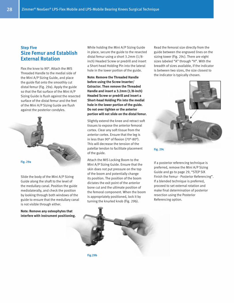
Step FiveSize Femur and Establish External Rotation
Flex the knee to 90°. Attach the MIS Threaded Handle to the medial side of the Mini A/P Sizing Guide, and place the guide flat onto the smoothly cut distal femur (Fig. 29a). Apply the guide so that the flat surface of the Mini A/P Sizing Guide is flush against the resected surface of the distal femur and the feet of the Mini A/P Sizing Guide are flush against the posterior condyles.
Slide the body of the Mini A/P Sizing Guide along the shaft to the level of the medullary canal. Position the guide mediolaterally, and check the position by looking through both windows of the guide to ensure that the medullary canal is not visible through either.
Note: Remove any osteophytes that interfere with instrument positioning.
Fig. 29a
While holding the Mini A/P Sizing Guide in place, secure the guide to the resected distal femur using a short 3.2mm (1/8-inch) Headed Screw or predrill and insert a Short-head Holding Pin into the lateral hole in the lower portion of the guide.
Note: Remove the Threaded Handle before using the Screw Inserter/Extractor. Then remove the Threaded Handle and insert a 3.2mm (1/8-inch) Headed Screw or predrill and insert a Short-head Holding Pin into the medial hole in the lower portion of the guide. Do not over tighten or the anterior portion will not slide on the distal femur.
Slightly extend the knee and retract soft tissues to expose the anterior femoral cortex. Clear any soft tissue from the anterior cortex. Ensure that the leg is in less than 90° of flexion (70°-80°). This will decrease the tension of the patellar tendon to facilitate placement of the guide.
Attach the MIS Locking Boom to the Mini A/P Sizing Guide. Ensure that the skin does not put pressure on the top of the boom and potentially change its position. The position of the boom dictates the exit point of the anterior bone cut and the ultimate position of the femoral component. When the boom is appropriately positioned, lock it by turning the knurled knob (Fig. 29b).
Fig.29b
Read the femoral size directly from the guide between the engraved lines on the sizing tower (Fig. 29c). There are eight sizes labeled “A” through “H”. With the breadth of sizes available, if the indicator is between two sizes, the size closest to the indicator is typically chosen.
Fig. 29c
If a posterior referencing technique is preferred, remove the Mini A/P Sizing Guide and go to page 29, “STEP SIX Finish the Femur - Posterior Referencing”. If a blended technique is preferred, proceed to set external rotation and make final determination of posterior resection using the Posterior Referencing option.

Zimmer® NexGen® LPS-Flex Mobile and LPS-Mobile Bearing Knees Surgical Technique 29
There are four External Rotation Plates: 0°/3° Left, 0°/3° Right, 5°/7° Left, and 5°/7° Right. Choose the External Rotation Plate that provides the desired external rotation for the appropriate knee. The 0° option can be used when positioning will be determined by the A/P axis or the epicondylar axis. Use the 3° option for varus knees. Use the 5° option for knees with a valgus deformity from 10° to 13°.
Attach the selected plate to the Mini A/P Sizing Guide (Fig. 29d).
Fig. 29d
Use a 3.2mm drill to drill through the two holes that correspond to the desired external rotation. Position two Headless Holding Pins, and impact them into the guide (Fig. 29e). Leave the head of the pin proud. If preferred, the MIS Headless Screws may be used. This will establish the desired external rotation from the posterior condyles.
Fig. 29e
Note: Do not impact the Headless Holding Pins flush with the External Rotation Plate.
Careful attention should be taken when placing the headless pins into the appropriate External Rotation Plate as these pins also set the A/P placement for the MIS Femoral Finishing Guide in the next step of the procedure. It is important to monitor the location of the anterior boom on the anterior cortex of the femur to ensure the anterior cut will not notch the femur. Positioning the anterior boom on the “high” part of the femur by lateralizing the location of the boom can often lessen the likelihood of notching the femur.
Unlock and rotate the boom of the guide medially until it clears the medial condyle. Then remove the guide, but leave the two Headless Holding Pins. These pins will establish the A/P position and rotational alignment of the Femoral Finishing Guide.
Step SixFinish the Femur
Option 1 Posterior Referencing Technique preferred technique for LPS-Flex Mobile
Option 2 Anterior Referencing Technique, page 32
Option 1 Posterior Referencing Technique Select the appropriate size MIS Femoral Finishing Guide (silver-colored for standard LPS femoral component) or MIS Flex Femoral Finishing Guide (gold-colored for LPS-Flex femoral component) as determined by the measurement from the A/P Sizing Guide. Additional bone is removed from the posterior condyles when using the flex finishing guide. Attach the Posterior Reference/Rotation Guide to the selected femoral finishing guide (Fig. 30a).
When implanting the LPS-Flex Mobile femoral component, the gold Femoral Finishing Guide is used. When implanting the LPS ‘non-Flex’ femoral component, the (silver colored) MIS Femoral Finishing Guide is used. (Reference page 29 “Option 1 – Posterior Referencing Technique” and page 32 “Option 2 – Anterior Referencing Technique”)
Fig. 30a

Zimmer® NexGen® LPS-Flex Mobile and LPS-Mobile Bearing Knees Surgical Technique30
Lock the femoral position locator on the rotation guide to the zero position (Fig. 30b). This zero setting ensures that, when the feet are flush with the posterior condyles, the amount of posterior bone resection will average 9mm when using the standard MIS Femoral Finishing Guides, and approximately 11mm when using the MIS Flex Femoral Finishing Guides.
Fig. 30b
Technique Tip: If between sizes and you don’t want to go to larger size, you may shift the femoral cutting block 2mm anterior using the +2mm setting to reduce chance of notching the femur.
Place the finishing guide on the distal femur, bringing the feet of the rotation guide flush against the posterior condyles of the femur (Fig. 30c).
Fig. 30c
Set the rotation of the finishing guide parallel to the epicondylar axis. Check the rotation of the guide by reading the angle indicated by the Posterior Reference/Rotation Guide. The epicondylar line is rotated externally 0°-8°, (4°±4°), relative to the posterior condyles. The external rotation angle can also be set relative to the posterior condyles, lining up the degrees desired.
Remove any lateral osteophytes that may interfere with guide placement. Position the MIS Femoral Finishing Guide mediolaterally. The width of the MIS Femoral Finishing Guide replicates the width of the NexGen CR and CRA femoral component which are 3-4mm wider than standard LPS femoral components (sizes C-G). The width of the MIS Flex Femoral Finishing Guide replicates the width of the NexGen LPS-Flex femoral components. Lateralization of the femoral component is desired. Note that mediolateral widths of the size B MIS Femoral Finishing Guide and size B MIS Flex Finishing Guide replicate the widths of standard LPS and LPS-Flex femoral components.
When the proper rotation and the mediolateral and anteroposterior position are achieved, secure the finishing guide to the distal femur. Use the Screw Inserter/Extractor to insert a 3.2mm Headed Screw or predrill and insert a Hex-head Holding Pin through the superior pinhole on the beveled medial side of the Femoral Finishing Guide (Fig. 30d). Then secure the lateral side in the same manner.
Fig. 30d
For additional fixation, drill the post holes using the Patellar/Femoral Drill Bit (Fig. 30e). Then insert 6.5mm x 35mm Periarticular Bone Screws through the post holes.
Fig. 30e
If a size A or B femoral component is chosen, do not drill the distal femoral post holes at this time. Size A and B femoral components have smaller pegs. The holes should be drilled using the size A/B Femoral Peg Drill and the Notch Guide.
If additional stability is needed, predrill and insert two Short-head Holding Pins through the inferior holes on one or both sides of the guide.
Use the Resection Guide through the anterior cutting slot of the finishing guide, and check the medial and lateral sides to be sure the cut will not notch the anterior femoral cortex (Fig. 30f).
Fig. 30f

Zimmer® NexGen® LPS-Flex Mobile and LPS-Mobile Bearing Knees Surgical Technique 31
Alternatively, the MIS Locking Boom Attachment can be attached to the face of the femoral finishing guide. Use the MIS Locking Boom or Telescoping Locking Boom to check the location of the anterior cut and determine if notching will occur (Fig. 30g). The boom tip indicates where the anterior femoral cut will exit the bone.
Fig. 30g
Use a 1.27mm (0.050-in.) narrow, oscillating saw blade to cut the femoral profile in the following sequence for optimal stability of the finishing guide (Fig. 30h):
1
4
32
Fig. 30h
1) Anterior condyles
2) Posterior condyles
3) Posterior chamfer
4) Anterior chamfers
Use the Patellar/Femoral Drill Bit to drill the post holes if not done previously.
Use the 1.27mm (0.050-in.) narrow, reciprocating saw blade to cut the base of the trochlear recess (Fig. 30i) and score the edges (Fig. 30j). Remove the finishing guide to complete the trochlear recess cuts and complete any remaining bone cuts.
Fig. 30i
Fig. 30j
Zimmer® NexGen® LPS-Flex Mobile and LPS-Mobile Bearing Knees Surgical Technique32
Fig. 30k
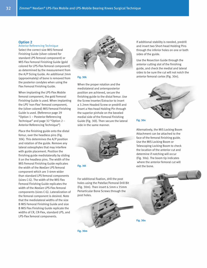
Option 2 Anterior Referencing Technique Select the correct size MIS Femoral Finishing Guide (silver colored for standard LPS femoral component) or MIS Flex Femoral Finishing Guide (gold colored for LPS-Flex femoral component) as determined by the measurement from the A/P Sizing Guide. An additional 2mm (approximately) of bone is removed from the posterior condyles when using the Flex Femoral Finishing Guide.
When implanting the LPS-Flex Mobile femoral component, the gold Femoral Finishing Guide is used. When implanting the LPS ‘non-Flex’ femoral component, the (silver colored) MIS Femoral Finishing Guide is used. (Reference page 29 “Option 1 – Posterior Referencing Technique” and page 32 “Option 2 – Anterior Referencing Technique”)
Place the finishing guide onto the distal femur, over the headless pins (Fig. 30k). This determines the A/P position and rotation of the guide. Remove any lateral osteophytes that may interfere with guide placement. Position the finishing guide mediolaterally by sliding it on the headless pins. The width of the MIS Femoral Finishing Guide replicates the width of the NexGen LPS femoral component which are 3-4mm wider than standard LPS femoral components (sizes C-G). The width of the MIS Flex Femoral Finishing Guide replicates the width of the NexGen LPS-Flex femoral components (sizes C-G). Lateralization of the femoral component is desired. Note that the mediolateral widths of the size B MIS Femoral Finishing Guide and size B MIS Flex Finishing Guide replicate the widths of CR, CR-Flex, standard LPS, and LPS-Flex femoral components.
When the proper rotation and the mediolateral and anteroposterior position are achieved, secure the finishing guide to the distal femur. Use the Screw Inserter/Extractor to insert a 3.2mm Headed Screw or predrill and insert a Hex-head Holding Pin through the superior pinhole on the beveled medial side of the Femoral Finishing Guide (Fig. 30l). Then secure the lateral side in the same manner.
Fig. 30l
For additional fixation, drill the post holes using the Patellar/Femoral Drill Bit (Fig. 30m). Then insert 6.5mm x 35mm Periarticular Bone Screws through the post holes.
Fig. 30m
If additional stability is needed, predrill and insert two Short-head Holding Pins through the inferior holes on one or both sides of the guide.
Use the Resection Guide through the anterior cutting slot of the finishing guide, and check the medial and lateral sides to be sure the cut will not notch the anterior femoral cortex (Fig. 30n).
Fig. 30n
Alternatively, the MIS Locking Boom Attachment can be attached to the face of the femoral finishing guide. Use the MIS Locking Boom or Telescoping Locking Boom to check the location of the anterior cut and determine if notching will occur (Fig. 30o). The boom tip indicates where the anterior femoral cut will exit the bone.
Fig. 30o

Zimmer® NexGen® LPS-Flex Mobile and LPS-Mobile Bearing Knees Surgical Technique 33
Remove the Headless Holding Pins from the Femoral Finishing Guide (Fig. 30p) with the Headless Pin Puller.
Use a 1.27mm (0.050-in.) narrow, oscillating saw blade to cut the femoral profile in the following sequence for optimal stability of the finishing guide (Fig. 30q):
1
4
32
Fig. 30p
Fig. 30q
1) Anterior condyles
2) Posterior condyles
3) Posterior chamfer
4) Anterior chamfers
Use the Patellar/Femoral Drill Bit to drill the post holes if not done previously.
Use the 1.27mm (0.050-in.) narrow, reciprocating saw blade to cut the base of the trochlear recess (Fig. 30r) and score the edges (Fig. 30s). Remove the finishing guide to complete the trochlear recess cuts and complete any remaining bone cuts.
Fig. 30r
Fig. 30s

Zimmer® NexGen® LPS-Flex Mobile and LPS-Mobile Bearing Knees Surgical Technique34
The critical goal is to create a rectangular and symmetrical flexion gap between the femur and tibia.
When establishing the mediolateral position of the femoral component, it is recommended to lateralize the component to help improve patellar tracking. Avoid positioning the component where it overhangs the bone as this may restrict flexion.
With the knee in flexion, remove posterior osteophytes with a 3/4-inch curve-on-flat osteotome (Fig. 30t). Use a laminar spreader and the Posterior Femoral Retractor to improve exposure (Fig. 30u).
Fig. 30t
Fig. 30u
Step SevenCheck Flexion Gap
Knee in 90° flexion
Use the Spacer/Alignment Guides or MIS Spacer/Alignment Guides to check ligament balance and joint alignment in flexion. Insert the Alignment Rod with Coupler into the guide and check the alignment of the tibial resection (Fig. 31). Then check ligament balance. If necessary insert progressively thicker Spacer Blocks until the proper soft tissue tension is obtained. When using the MIS Flex Femoral Finishing Guide, the flexion gap will be greater than the extension gap. Use the LPS-Flex Spacer Block Adapter to simulate the LPS-Flex component posterior condyle dimension for sizes C-G.
Fig. 31
Note: Do not use the CR-Flex Spacer Block Adapter since it simulates the CR-Flex component posterior condyle dimension and will result in inaccurate representation of the LPS-Flex flexion gap.
Balance Flexion/Extension GapsKnee in extension
Attach the Alignment Rod to the Alignment Rod with Coupler. Check ligament balance and limb alignment in extension.
If the tension is significantly greater in extension than in flexion, re-cut the distal femur using the appropriate instrumentation. This will enlarge the extension space.
If the tension is significantly less in extension than in flexion, either use a minus-size femur or perform additional ligament releases.

Zimmer® NexGen® LPS-Flex Mobile and LPS-Mobile Bearing Knees Surgical Technique 35
Step EightPatellar Preparation
Note: If the surgeon determines that the condition of the patient’s patella is satisfactory, it is not necessary to resurface the patella. The geometry, depth, and length of the patellar groove on the NexGen Femoral Component accommodate the unresurfaced patella.
Using the desired patella preparation technique, resurface the articular surface of the patella. Be sure to determine the appropriate patella thickness. When drilling the peg holes for the patellar component, position the Patellar Drill Guide so as to medialize the patellar implant. (When the patella is everted, this means placing the guide on the lateral border.)
Step NineFinishing the Tibia Option 1: Using the NexGen Fluted Stem Mobile Tibial Component
Select the proper size Tibial Sizing/Positioning Plate that provides the desired tibial coverage. Be sure that one of the three femoral component sizes designated on the anterior surface of the plate matches the femoral provisional size.
The tibia can be finished before the trial reduction if the implant position will be chosen based on anatomic landmarks. Alternatively, the sizing plate and provisionals can be used to perform a trial range of motion to aid in tibial positioning.
Position Based on Anatomic Landmarks
Attach the Mobile Bearing Knee Tibial Holding Clamp to the selected sizing plate by placing the cutout of the clamp over the anterior rail of the plate. Secure it by tightening the thumb screw (Fig. 32a).
Fig. 32a
Align the handle of the holding clamp with the anterior aspect of the tibia. Use the Alignment Rod to aid in confirming varus/valgus alignment and posterior slope. Position the plate so the handle of the holding clamp points at, or slightly medial to, the midpoint of the tibial tubercle. Then pin the plate in place with two Small-head Holding Pins. Ensure that the sizing plate remains in the proper position when pinning.
Proceed to Page 34 (2nd column) to complete tibial preparation.
Optional Technique:Position Based on Trial Range of Motion
Insert the proper Femoral Provisional, Tibial Sizing/Positioning Plate, and Articular Surface Provisional. Ensure that soft tissue balance is appropriate.
Insert a Small-head Holding Pin through the anterior hole on the rail of the sizing plate (Fig. 32b). This will hold the Articular Surface Provisional in a fixed central position on the sizing plate.
Fig. 32b

Zimmer® NexGen® LPS-Flex Mobile and LPS-Mobile Bearing Knees Surgical Technique36
Flex and extend the knee with the provisionals in place (Fig. 32c).
Fig. 32c
If the Articular Surface Provisional lifts off anteriorly during flexion, check the resected bone surface and remove any bony protrusions. If this lift-off occurs and the resected bone surface is smooth, perform an additional release of the posterior capsule. Flex and extend the knee again with the provisionals in place to determine the location of the plate. Once proper soft tissue balancing is complete, the tibial component tends to seat itself in the position where it best articulates with the femur.
After the location of the plate has been determined, insert the temporary Small-head Holding Pins through the angled holes on the front rail of the sizing plate (Fig. 32d).
Fig. 32d
Remove the Small-head Holding Pin, the Articular Surface Provisional, and the Femoral Provisional. Then insert Small-head Holding Pins through the holes in the top of the Tibial Sizing/Positioning Plate to mark the location of the plate when using the broaching plate in the next step (Fig. 32e).
Fig. 32e
Remove any pins and the Tibial Sizing/Positioning Plate. Place the same size Fluted Stem Tibial Broach Plate onto the tibial surface. Use the holes created by the Small-head Holding Pins that secured the Tibial Sizing/Positioning Plate to determine the proper location of the Fluted Stem Tibial Broach Plate. Secure the plate with Short-head Holding Pins through the existing holes.
Place the Tibial Drill Guide on the sizing plate and drill for the stem with the 15mm Drill (Fig. 32f). Drill until the first engraved line on the drill is in line with the top of the drill sleeve. Then remove the Tibial Drill Guide.
Fig. 32f
Assemble the proper size Fluted Stem Tibial Broach to the Broach Impactor (Fig. 32g).
Fig. 32g
Note: If you plan to use a stem extension, drill until the first exgraved line on the drill is approximately 10mm past the top of the drill sleeve.

Zimmer® NexGen® LPS-Flex Mobile and LPS-Mobile Bearing Knees Surgical Technique 37
The broach can be assembled only from the front. Seat the impactor on the broach plate and impact the broach to the proper depth indicated by the etched groove on the shaft aligning with the impactor handle (Fig. 31h). The broach has a built-in stop so it cannot be over impacted (Fig. 32i).
Fig. 32h
Remove the impactor assembly using the built-in slaphammer, then remove the Fluted Stem Broach Plate. Use the correct size tibial plate provisional to ensure proper fit before implanting the final components.
Fig. 32i

Zimmer® NexGen® LPS-Flex Mobile and LPS-Mobile Bearing Knees Surgical Technique38
Fig. 33b
Fig. 33c
Fig. 33a
Step NineFinishing the Tibia Option 2: Using NexGen MIS LPS-Mobile Tibial Component
Note: If using the Headless Pins or Small-Head Holding Pins, predrill using the 3.2mm Bone Screw Drill.
Select the appropriate size MIS LPS-Flex Mobile Broach Plate (Fig. 33a).
Base the selection first on achieving good mediolateral coverage, and then anteroposterior coverage.
Verify that the femoral and tibial component sizes will be compatible. If there is a femoral/tibial mismatch, consider using the fixed bearing system.
Assemble the LPS-Flex Mobile Broach and Trialing Plate. Position the Trialing Plate onto the Broach Plate (Fig. 33b) so that the peg on the under side of the Trialing Plate mates with the anterior hole on the proximal surface of the Broach Plate. Align the peg and hole to prevent bending the peg. Snap the plates together tightly (Fig. 33c & 33d). Note: If the plates are not tightly snapped, it will interfere with trialing.
Fig. 33d
Position Base on Anatomic Landmarks Attach the MIS Sizing Plate Handle to the Broach and Trialing Plate Assembly (Fig. 33e). The handle should be inserted on the medial side of the Broach Plate to provide clearance for the patella. Extend the lever on the handle and engage the tabs on the handle with the grooves on the Broach Plate by positioning the lever lateral to the dovetail, and clamp the lever to secure.
Fig. 33e
Ensure that the Broach and Trialing Plate Assembly is positioned as far posteriorly as possible on the lateral side without overhanging the tibia. This position may leave some bone exposed on the posteromedial tibia when the plate lines up with the posterolateral cortex.
Insert a Small Head Holding Pin into the lateral pin hole on the top face of the Broach Plate (Fig. 33f).

Zimmer® NexGen® LPS-Flex Mobile and LPS-Mobile Bearing Knees Surgical Technique 39
Fig. 33h
Fig. 33f
Fig. 33g
When using the anterior oblique pin holes, pay special attention to the posterior aspect of the sizing plate to ensure lift-off does not occur from over tightening/seating. In extension, apply a valgus stress to view or palpate the lateral side of the tibia to check Broach Plate fit laterally.
Be sure that the component is properly positioned rotationally. Broach plate rotation and varus/valgus alignment can be checked by inserting the Alignment Rod through the hole or slot in the handle of the MIS Sizing Plate Handle (Fig. 33h). There are two options available for use of the alignment rod:
• Slot – check varus/valgus and rotational alignment
• Round hole – check slope of tibial cut
Optional Technique
Position Based on Trial Range of Motion Insert the proper size Femoral Provisional, Assembled Broach and Trialing Plates, and Articular Surface Provisional. Insert a Small-head Holding Pin through the anterior hole on the rail of the Trialing Plate. This will hold the Articular Surface Provisional in a fixed central position on the Trialing Plate.
Flex and extend the knee with the provisionals in place. With proper soft tissue balancing complete, the tibial component tends to seat itself in the position where it best articulates with the femur.
After this process has occurred, mark the position of the component with methylene blue, electrocautery, or by placing a pin or MIS Screw in the sizing plate anteriorly. Pin the broach plate in place with Small head holding pins. It is recommended to use one anterior pin hole and one hole on the opposite side of the broach plate on the plate face to assure plate stability. Ensure that the Broach Plate remains in the proper position when pinning.
Proceed to Step Eleven.
Note: Ensure that the trialing plate peg does not catch on the broach plate during removal.
Only the Small Head Holding Pins may be used through the top face of the Broach Plate. This pin will allow the Articular Surface Provisional to rotate on the assembled Broach and Trialing Plate.
It is recommended to use one hole on the top Broach Plate face and one anterior oblique hole on the opposite side if additional plate stability is needed.
A short-head pin or MIS Screw is inserted into the medial anterior oblique hole on the Broach Plate (Fig. 33g).
Note: Do not pin through the anterior oblique hole and top face hole on the same side. In this arrangement, the pins may interfere, on smaller sizes.
At this point in the procedure, perform a trial range of motion (Step Ten, Page 39) as an added check to ensure proper flexion and extension gap balancing prior to broaching the tibia.
27 or 33mmHeaded Screw Pin

Zimmer® NexGen® LPS-Flex Mobile and LPS-Mobile Bearing Knees Surgical Technique40
Fig. 33l
Use the Slaphammer Extractor or small osteotome to remove the Trialing Plate, leaving the Broach Plate in place on the tibia (Fig. 33i). Avoid torquing the Trialing Plate during removal as this could damage the peg on the inferior surface (Fig. 33j).
Fig. 33i
Fig. 33k
Technique Tip – When encountering unusually hard, sclerotic bone on the proximal tibia, it is recommended to prepare the tibia prior to broaching. Attach the MIS Threaded Handle to the MIS Drill Bushing and position it on the Broach Plate (Fig. 33k). Hold the MIS Drill Bushing in place while drilling to ensure it remains in full contact with the broach plate. Using the Cemented Drill, drill half the distance to the engraved line on the Cemented Drill (Fig. 33l). This depth will prepare for the length of the keel.
Note: Make sure detents are engaged and bushing remains in full contact with the sizing plate during drilling.
Fig. 33j
Assemble the proper size MIS Cemented Broach to the MIS Tibial Broach Impactor (Fig. 33m).
Seat the MIS Tibial Broach Impactor assembly in the corresponding Broach Plate holes (Fig. 33n).
During broaching, make sure that the broach handle remains flush against the Broach Plate and in full contact with the Broach Plate and that the broach handle does not toggle during impaction.
Fig. 33m
Fig. 33n

Zimmer® NexGen® LPS-Flex Mobile and LPS-Mobile Bearing Knees Surgical Technique 41
Remove the Tibial Broach Impactor assembly and MIS Tibial Sizing Plate (Fig. 33q).
• Impact the under surface of the impaction head in the center of the anterior portion of the collar beneath the impaction head.
• Maintain a vertical impact direction in order to extract the broach straight out of the bone and avoid disruption of the broach preparation. Vertical extraction will also reduce stress on the instrument.
Caution: Do Not extract with mallet blows on either the medial or lateral side of the under surface of the impaction head.
Do Not attempt to extract the broach with a horizontal or angled blow on any side of the MIS Broach Impactor Handle.
Fig. 33q
Fig. 33p
Fig. 33r
Impact the MIS Tibial Broach Impactor assembly with care to prevent fracture of the tibia (Fig. 33o).
Fig. 33o
The orientation of the broach handle is important to ensure proper and complete broaching, resulting in full seating of the tibial implant on the bone.
Caution: During impaction, take care not to move the Broach Handle anteriorly.
Broaching is complete when the Impactor Knob is fully seated against the MIS Broach Impactor and the instrument bottoms out on the handle stop (Fig. 33p).
The tibial bone plug may not be fully removed by the hollow broach. A Kocher or small rongeur can be used to fully remove remaining bone (Fig. 33r).
Remove the Broach Plate.

Zimmer® NexGen® LPS-Flex Mobile and LPS-Mobile Bearing Knees Surgical Technique42
Step TenTrial Reduction
Place the Femoral Provisional, the Tibial Plate Provisional, the Articular Surface Provisional, the Patellar Provisional and Stem Extension Provisional, if necessary, onto the prepared bone surfaces.
With all the provisional components in place, perform a complete range of motion. Observe patellar tracking and tilt. If necessary, perform a lateral retinacular release.
Step Eleven
Implantation Option 1: Using the NexGen Fluted Stem Mobile Tibial Component
After the implants have been chosen, make one last check to ensure that the femoral, tibial, and articular surface components match. The femoral letter must match one of the letters on the articular surface carton. The tibial plate
Check to ensure that the set-screw has not migrated into the mobile tibial stem base taper prior to inserting the stem extension. Insert the stem extension into the stem-base of the mobile tibial component. When using the Offset Stem Extension, line up the stem location number with the etched line on the posterior stem base housing. The stem extension should be “snug” in the tibial component stem base. If toggle exists, back out the set-screw one half turn. When a snug fit is achieved, wrap the mobile tibial component in a cloth and place it on a surgical cart to provide a rigid surface for taper impaction. While protecting the stem extension, strike it solidly one time with a two-pound mallet.
Note: Hitting the stem more than once may loosen the taper connection.
After seating the Morse-type taper, tighten the set-screw located on the posterior aspect of the mobile tibial base plate stem (Fig. 34a) using a standard 3.5mm hex screwdriver.
Note: If, in the surgeon’s opinion, a stem is not needed, then the set-screw should be removed before implanting the tibial base plate.
Insert the appropriate size femoral and tibial components. Then insert the appropriate tibial articular surface onto the plate.
Fig. 34a
number must match one of the three numbers indicated on the articular surface carton as indicated by the interchangeability chart.
If desired, a Straight or Offset Stem Extension can be used with the Precoat Fluted Stem Mobile Tibial Base Plate. The locking mechanism between the mobile tibial implant and the stem extension implant is a combination of a Morse-type taper and a set-screw. Remove the stem extension locking screw from the stem extension and discard. The stem extension locking screw is not used with the mobile tibial component.
The LPS-Flex Mobile and LPS-Mobile Bearing Knee Systems are compatible with all available sizes of NexGen stem extensions, which consist of the following designs:
• Straight Stem • Straight Stem - Long • Offset Stem • Offset Stem - Long • Sharp Fluted Stem • Sharp Fluted Stem - Long • Cemented Stem
Fig. 34b
Techniques for 17mm and 20mm Articular Surface AssemblyA secondary locking screw is required for the 17mm- and 20mm-thick articular surface components (Fig. 34b). Either of two assembly techniques can be used.
Intraoperative Technique:Apply bone cement to the underside of the tibial base plate, around the stem on the resected tibial surface and in the tibial IM canal. Implant the tibial base plate and wait for the bone cement to completely cure. Then insert the articular surface onto the trunnion of the base plate. Place the secondary locking screw (packaged with the articular surface) through the hole in the articular surface.
Select the Tibial Plate Wrench which has the tibial plate size that matches the implant size to be assembled. Place the end of the wrench over the tibial plate. Ensure that the wrench is in line with the base of the tibial plate. Attach the Deflection Beam Torque Wrench to the 4.5mm Hex Driver Bit. Apply 95 in.-lbs. of torque with the wrench. Do not-over or under-torque.
Optional Back-Table Technique:The tibial plate may be placed onto the holding fixture, which is an integral part of the instrument case. Assemble the articular surface onto the trunnion of the tibial plate. Insert the secondary locking screw through the hole in the articular surface.
Attach the Deflection Beam Assembly Wrench to the 4.5mm Hex Driver Bit. Apply 95 in.-lbs. of torque with the wrench. Do not over or under torque.

Zimmer® NexGen® LPS-Flex Mobile and LPS-Mobile Bearing Knees Surgical Technique 43
Step ElevenImplantation Option 2: Using the NexGen MIS LPS-Mobile Tibial Component
In this step, the final components are implanted, and the tibial articular surface is secured to the implanted tibial base plate.
After the implants have been chosen, make a final check to ensure that the femoral, tibial base plate, and tibial articular surface components match. Mix the cement. The cement should have a doughy consistency when ready for use.
Tibial Base PlatePosition the PCL Retractor posteriorly, the Collateral Soft Tissue Protector laterally, and the Collateral Retractor medially. Sublux the tibia anteriorly. Apply bone cement to the underside of the tibial baseplate, around the keel, on the resected tibial surface and in the IM canal. Position the tibial base plate onto the tibia and use the Tibial Impactor to impact it until fully seated (Fig. 35a). Thoroughly remove any excess cement in a consistent manner.
Femoral ComponentKnee in 70°-90° flexion
Place the Collateral Retractor laterally, an Army-Navy retractor anteriorly, and a rake retractor on the meniscal bed medially.
Place a layer of cement on the underside of the prosthesis and in the holes drilled in the femur.
Attach the Femoral Impactor/Extractor to the femoral component. Insert the femoral component onto the distal femur by translating the component laterally until the lateral peg aligns with the drill hole in the lateral femoral condyle. Take care to avoid scratching the implant component surfaces. Disposable, plastic Tibial Plate Protectors may be temporarily inserted onto the tibial base plate to protect the implant surfaces during insertion of the femoral component. Remove the Tibial Plate Protector after the femur is seated. Be sure that soft tissue is not trapped beneath the implant. Use a mallet to impact the component until fully seated.
Remove the Femoral Impactor/Extractor, and the retractors. Use the Femoral Impactor and Mallet to make sure the femoral component is fully impacted. Check the medial and lateral sides to make sure the femoral component is fully impacted. Remove any excess cement in a thorough and consistent manner.
Fig. 35a Use the Tibial Impactor to impact the tibial base plate.
Fig. 35b

Zimmer® NexGen® LPS-Flex Mobile and LPS-Mobile Bearing Knees Surgical Technique44
Tibial Articular Surface Implantation Knee in 70°-90° flexion
When the appropriately-sized tibial, femoral and patellar implant components have been implanted, allow the bone cement to cure. The articular surface provisional may be inserted to perform another trial reduction to confirm the articular surface thickness. When the desired articular surface has been determined, the articular surface implant may be inserted.
With the knee in approximately 90° of flexion, place the Articular Surface Implant against the distal portion of the femoral component with the spine of the articular surface fitting into the intercondylar notch of the femoral component. The distal condyles of the femoral component will be in contact with the articular surface (Fig. 35c).
Next, bring the tibia into extension while the articular surface is held in place against the femoral component. Axial rotation and distraction of the tibia will facilitate assembly and help prevent contact of the proximal portion of the tibial plate trunnion with the distal surface of the articular surface. As the tibia is brought into extension, the articular surface will engage the tibial plate trunnion as the knee reaches full extension (Fig. 35d).
Fig. 35d
Fig. 35c
Techniques for 17mm and 20mm Articular Surface Assembly A secondary locking screw is required for the 17mm- and 20mm-thick articular surface components.
Once the articular surface has been implanted, place the secondary locking screw (packaged with the articular surface) through the hole in the articular surface (Fig. 35e).
Fig. 35e
Attach the MIS Counter Torque Wrench to the Articulating Surface Stop on the Tibial Plate (Fig. 35f).
Tighten the MIS Counter Torque Wrench by turning the knob clockwise. Ensure that the hooks are flush with the top surface of the tibial plate. Do not over-tighten.
Alternatively, the LCCK Tibial Plate Wrench that matches the size of the implant may be used. Place the end of the wrench over the tibial base plate. Ensure that the wrench is in line with the base of the tibial base plate.
Use the LCCK Deflection Beam Torque Wrench with the 4.5mm Hex Driver Bit to torque the screw to 95 in-lbs. Do not overtorque or undertorque.
Loosen the MIS Counter Torque Wrench by turning the knob counter clockwise.
Fig. 35f
NexGen All-polyethylene PatellaKnee in 70°-90° flexion
Apply cement to the anterior surface and pegs of the patellar component while in a doughy consistency. Locate the drilled peg holes and use the Patellar Clamp to insert and secure the patella in place. Fully open the jaws of the clamp and align the teeth to the anterior surface of the patella and the plastic ring to the posterior surface of the implant. Use the clamp to apply a significant amount of pressure to the implant to fully seat the implant on the patellar surface. Then remove excess cement.

Zimmer® NexGen® LPS-Flex Mobile and LPS-Mobile Bearing Knees Surgical Technique 45
Fig. 36b
Fig. 36a
Position the knee in flexion to continue closing the layers (Fig. 36b).
Rehabilitation Protocol
An equally important factor in gaining or maintaining high flexion after successful total knee arthroplasty is early and/or aggressive rehabilitation of the patient. Many of the standard rehabilitation protocols used in western-style hospitals today are aimed at restoring knee motion and function between 90˚ and 110˚, which is sufficient for the TKA patient to get into or out of a chair or a car. Those patients undergoing TKA who are able and willing to flex and wish to maintain preoperative flexibility may be better off with earlier and/or relatively more aggressive rehabilitation exercises.
References
1 Whiteside LA. Factors affecting range of motion in total knee arthroplasty. J Jpn Orthop Assoc. 1991;65:193-194.
2 Insall JN. Surgery of the Knee. 3rd ed. New York, NY: Churchill Livingston; 2001:1553.
Closure
Close the capsule and perform a “drop and dangle” test to predict the range of motion for the patient (Fig. 36a).

Zimmer® NexGen® LPS-Flex Mobile and LPS-Mobile Bearing Knees Surgical Technique46
Fig. 37b
Tibial Spacer Block to ensure that enough tibial bone has been removed (Fig. 37a). Check the flatness and slope of the tibial cut. Insert the Alignment Rod to check that the tibial cut is perpendicular to the longitudinal axis of the tibia (Fig. 37b).
Ensure rectangular flexion/ extension gaps. Perform further ligament balancing as needed.
Fig. 37a
When the proximal tibial bone has been removed, resect any remaining meniscus and bone fragments. Remove femoral and tibial osteophytes. Take care to remove any remaining posterior osteophytes.
Check Tibial ResectionThe surface of the tibia should be parallel to the epicondylar axis. Since further bone resection is based on the flat tibial cut, insert the Flexion Balancing
Step One
Flexion Balancing InstrumentsThe NexGen Flexion Balancing Instruments are designed to help accomplish the goals of total knee arthroplasty with instruments that fit the surgeons’ instrument philosophy by combining soft tissue balancing with alignment accuracy in a simple, straight-forward technique.
Like the Multi-Reference 4-in-1 Instruments, these instruments and technique assist the surgeon in restoring the center of the hip, knee, and ankle to lie on a straight line, establishing a neutral mechanical axis. The femoral and tibial components are oriented perpendicular to this axis. Femoral rotation is determined using the posterior condyles and epicondylar axis as references.
The flexion gap is created first. The distal cut of the femur is determined by the flexion gap. The instruments promote accurate cuts to help ensure secure component fixation.
The following should be considered when planning to use the Flexion Balancing Instruments:
• The patient should have stable and functional collateral ligaments.
• If the patient has an angular deformity, it should be less than 20° since it is more difficult to achieve ligament balance in these patients.
• The anticipated size of the femoral component, based on preoperative templating should be size C-G.
The instruments are intended to be used only to implant NexGen LPS-Flex Femoral Components. Ample component sizes allow soft tissue balancing with appropriate soft tissue release.
Preoperative Planning
Flexion Balancing Instruments The surgical technique helps the surgeon ensure that anatomic alignment of 4° to 6° valgus angulation to the mechanical axis is achieved. A full leg A/P radiograph may be helpful in preoperative assessment and planning. Long radiographs are useful for determining the mechanical axis relative to the anatomical axis of the femur and for identifying deviations from the axis and deformities in the diaphyseal area of the femur and tibia that might be overlooked in more localized radiographs.
The mechanical and anatomical axes of the leg can be precisely plotted and the femoral angle α, representing the difference between the two, can be determined. This angle, which is usually about 6°, but may vary depending on morphology and patient size, is important for choosing the appropriate femoral angle bushing and therefore a correct positioning of the distal femoral cut.
By lengthening the line of the anatomical axis of the femur, it can be shown that the entry point for the intramedullary alignment guide does not necessarily lie in the center of the femoral condyle, but most of the time slightly medial to this point.
Appendix A: NexGen Flexion Balancing Instruments

Zimmer® NexGen® LPS-Flex Mobile and LPS-Mobile Bearing Knees Surgical Technique 47
Step TwoDrill Femoral Medullary Canal
Use the 8mm IM Drill to drill a hole in the center of the patellar sulcus of the distal femur making sure that the drill is parallel to the shaft of the femur in both the anteroposterior and lateral projections (Fig. 38a). The hole should be approximately one-half to one centimeter anterior to the origin of the posterior cruciate ligament. Medial or lateral displacement of the hole may be needed according to preoperative templating of the A/P radiograph.
Fig. 38a
The optional IM Hole Locater may be used to position the access point for the medullary canal (Fig. 38b).
The drill is fluted to reduce intramedullary pressure during placement of subsequent IM guides. Suction the canal to remove medullary contents.
Insert the IM Rod into the medullary canal. The Handle with Quick Connection will facilitate insertion (Fig. 38c).
Fig. 38b
Fig. 38c
The IM Rod is available in two lengths. The rod on the standard instrument is 335mm (13.5 in) long and the rod on the short instrument is 204mm (8 in). Choose the length best suited to the length of the patient’s leg, which will provide the most accurate reproduction of the anatomic axis. If the femoral anatomy has been altered, as in a femur with a long-stemmed hip prosthesis or with a femoral fracture malunion, use the short IM Rod.
The IM Rod should not be inserted to the full length of the instrument but to the length best suited to help ensure the most accurate replication of the anatomic axis. The largest outer diameter of the IM Rod should be outside the canal by at least 6cm (3 in) to mate correctly with other instruments in the technique.

Zimmer® NexGen® LPS-Flex Mobile and LPS-Mobile Bearing Knees Surgical Technique48
Step ThreeSize the Femur
Flex the knee to 90°.
Use electrocautery or a marking pen to mark the anatomic references for the A/P and transepicondylar axes on the femur (Fig. 39a).
Fig. 39d
The boom tip should contact the anterior sulcus of the femur (Fig. 39d). Ensure that the skin does not put pressure on the top of the boom and potentially change its position. The sizer body should be positioned in the middle of the condyles. To get an accurate reading, the feet of the A/P sizer must be flush against the posterior condyles.
Fig. 39e
The MIS Threaded Handle can be attached to the Femoral A/P Sizer to aid in positioning (Fig. 39b).
Slide the Femoral A/P Sizer over the IM Rod and move the boom to the highest position (near H) to clear the anterior femur (Fig. 39c).
Read the femoral size directly from the etched sizing lines on the instrument with the engraved line (Fig. 39e). There are eight sizes labeled “A” through “H”. If the indicator is between two sizes, the closest size is typically chosen. Note: If the size is A, B or H, a different femoral preparation instrument system will be needed.
Fig. 39a
Fig. 39b
Fig. 39c
The final determination of femoral size is confirmed in Step Seven with the MIS Flex Femoral Finishing Guide.
Mark the point on the anterior sulcus of the boom tip position. Then remove the Femoral A/P Sizer.

Zimmer® NexGen® LPS-Flex Mobile and LPS-Mobile Bearing Knees Surgical Technique 49
Determine A/P Position Flex the knee to 90°.
Slide the A/P Cut Guide assembly over the IM Rod (Fig. 40f).
Fig. 40g
Fig. 40h
Step FourEstablish Femoral Rotation
In this step, preliminary anterior and posterior femoral cuts are made. Final femoral cuts will be performed in Step Seven.
Back table preparationSelect the appropriate size A/P Cut Guide (Fig. 40a). The A/P Cut Guides are available in sizes C through H.
Move the locking mechanism down to the “unlocked” position to open the track for the Angle Bushing (Fig. 40b). Make sure that the thumb screw is completely untightened.
Select the Angle Bushing determined during preoperative templating. There are four Angle Bushings — left and right configurations of 4° and 6° (Fig. 40c).
Slide the selected Angle Bushing into the A/P Cut Guide (Fig. 40d). The Angle Bushing should move freely.
Fig. 40e
Use the Hex Head Screwdriver and secure the TF Telescoping Boom to the A/P Cut Guide (Fig. 40e).
Fig. 40c
Fig. 40d
Locked Unlocked
Fig. 40f
Slide the TF Telescoping Boom onto the anterior femur. The boom tip should contact the point on the anterior sulcus of the femur defined during sizing. Move the locking mechanism up into the “locked” position (Figs. 40g, 40h & 40i).
Fig. 40a
Fig. 40b

Zimmer® NexGen® LPS-Flex Mobile and LPS-Mobile Bearing Knees Surgical Technique50
Fig. 40i
Use the Resection Guide through the anterior cutting slot and check the medial and lateral sides to be sure the cut will not notch the anterior femoral cortex.
Use the Female Hex Driver to tightly secure the locking mechanism to ensure no movement of the Angle Bushing during balancing and bone resection. Tighten the thumb screw on the locking mechanism with the Female Hex Driver (Fig. 40j). The thumb screw must be securely tightened so that it will not loosen when under tension.
Fig. 40j
Balance the Knee in FlexionBe sure that the NexGen Balancer is not extended (Fig. 40l).
Press and hold the Release Button on the NexGen Balancer (Fig. 40o).
Fig. 40k
Position the NexGen Balancer onto the resected tibia. Insert the prongs into the bottom slots of the A/P Cut Guide (Fig. 40n).
Fig. 40n
Fig. 40l
With the Female Hex Driver, turn the knob on the bottom of the NexGen Balancer clockwise (Fig. 40p).
Fig. 40o
Fig. 40p
Note: The Release Button must be pressed to expand the NexGen Balancer. However, it does not need to be pressed to reduce it.
Once the locking mechanism is tightened, remove the TF Telescoping Boom (Figs. 40k). If needed, the 3.5mm Hex-head Screwdriver can be used to aid in removal. The A/P Cut Guide will now rotate about the IM Rod.
Open/Extended Closed
Use the Female Hex Driver to close the NexGen Balancer (Fig. 4m).
Fig. 40m

Zimmer® NexGen® LPS-Flex Mobile and LPS-Mobile Bearing Knees Surgical Technique 51
Fig. 40t
Fig. 40u
Make sure that the A/P Cut Guide is flush with the distal femur. If the instrument has moved away from the distal femur, move it back into position.
Note: If any soft tissue adjustments are necessary, they must be done before pinning the A/P Cut Guide. If the soft tissues are not balanced adequately, incorrect bone cuts may result.
Pin the A/P Cut Guide using a combination of holes for the most secure fixation (Fig. 40u). Use at least one angled hole to keep the A/P Cut Guide flush to the femur during bone resection.
Fig. 40q
Remove the NexGen Balancer.
Fig. 40r
Fig. 40s
The NexGen Balancer’s stop mechanism will stop at the markings on the face of the Balancer. These markings reference an articular surface thickness. However, the final determination of articular surface thickness is made during provisional trialing.
Note: You may need to release some tension in order to depress the Release Button.
Do not overexpand/tense the NexGen Balancer. Stop tensioning when manual feedback indicates soft tissue resistance. If between two measures, stop pressing the release button and allow the indicator to return to the thinner size. Note the measure as this will be the desired measurement for the extension gap (Fig. 40q).
Alternatively, the optional Torque Driver can be used instead of the Female Hex Driver. Use the Torque Driver with the NexGen Balancer to distract the femur from the tibia. Note the number on the scale required to set this displacement (Fig. 40r). Utilizing a lower joint force, ie, 1 or 2 on the scale, may predict articular thickness more accurately. Utilizing a higher joint force, ie, 5 or 6 on the scale, may magnify any soft tissue imbalances. Do not overtorque the instrument past the 6 marking.
Check A/P landmarks on the A/P Cut Guide with bony landmarks previously drawn on the femur (Fig. 40s). There is an etch mark on the superior surface of the A/P Cut Guide which can be used as a reference to the A/P axis.
The epicondylar landmark can be checked by inserting two headless pins into the holes on the side of the A/P Cut Guide and referencing the epicondylar line previously drawn on the femur (Fig. 40t).

Zimmer® NexGen® LPS-Flex Mobile and LPS-Mobile Bearing Knees Surgical Technique52
Note: Take care to protect the patellar tendon and collateral ligaments during resection.
The final femoral finishing cuts will be made in Step Seven.
Fig. 40v
Fig. 40w
To facilitate removal of the NexGen Balancer, close the NexGen Balancer with the Female Hex Driver, turning the knob counter-clockwise (Fig. 40v).
Preliminary Anterior and Posterior ResectionWhen satisfied with the soft tissue tension and the femoral rotation use a 1.27mm (0.050-in.) narrow, oscillating saw blade and make the preliminary anterior and preliminary posterior cuts (Fig. 40w).
Step 5Position the Distal Cut Guide
Knee flexed 90°
The Distal Cut Guide consists of two pieces — a proximal section and a distal section (Fig. 41a).
Fig. 41a
Attach the proximal end of the Distal Cut Guide, the part with the push-button locking mechanism to the Distal Placement Guide. Then place the Distal Placement Guide tab into the top slot of the A/P Cut Guide (Fig. 41c).
Fig. 41b
Secure the proximal end of the Distal Cut Guide by inserting two 3.2mm Headed Screws, or predrill and insert Headed Holding Pins (Fig. 41d).
Fig. 41c
Fig. 41e
Fig. 41d
Remove the Distal Placement Guide The MIS Threaded Handle can be used to facilitate removal of the Distal Placement Guide (Fig. 41e).
The Distal Placement Guide is used to position the proximal section of the Distal Cut Guide on the anterior femur (Fig. 41b).
Proximal
Distal

Zimmer® NexGen® LPS-Flex Mobile and LPS-Mobile Bearing Knees Surgical Technique 53
Check Flexion GapUse the LPS-Flex Spacer/Alignment Guides to check the flexion gap. The LPS-Flex Spacer/Alignment Guides simulate the posterior condyle thickness of the LPS-Flex Femoral Component.
With the knee in flexion, insert the flexion side of the thinnest appropriate LPS-Flex Spacer/Alignment Guide between the resected surfaces of the posterior femur and tibia (Fig. 41g). Insert the Alignment Rod into the guide and check the alignment of the tibial resection. If necessary insert progressively thicker LPS-Flex Spacer/Alignment Guides until the proper soft tissue tension is obtained.
Remove the A/P Cut Guide, and IM Rod. (Fig. 41f)
Fig. 41f
Note: The flexion side of the LPS-Flex Spacer/Alignment Guide should only be used to reference the preliminary resection of the posterior condyles, not the final resection.
Step SixResect Distal Femur
Leg in extension
Attach the distal section of the Distal Cut Guide. Press the push button and position the indicator at the 0mm mark (default distal cut position) (Fig. 42a).
Fig. 42a
To check femoral alignment, the Alignment Arch can be positioned in the same holes used for the Distal Placement Guide (Fig. 42b).
Fig. 42c
Use the Hex-head Screwdriver or Torque Driver with the NexGen Balancer to distract the femur from the tibia until the soft tissues are tense. Note the measurement on the NexGen Balancer (Fig. 42d). The extension gap should match the flexion gap. In addition, if using the Torque Driver, equivalent forces in flexion and extension should be used.
Fig. 42d
Fig. 42e
Perform any necessary soft tissue releases.
Attach the NexGen Balancer to the Distal Cut Guide (Fig. 42c).
Fig. 42b
If desired, the distal cut position can also be adjusted to match the measurement of the flexion gap. Release the NexGen Balancer to remove tension on the joint. Press the push-button locking mechanism, and slide the distal portion of the Distal Cut Guide. The distal cut can be adjusted at +4mm, +2mm, -2mm, or -4mm from the neutral cut position (Fig. 42e).
Fig. 41g

Zimmer® NexGen® LPS-Flex Mobile and LPS-Mobile Bearing Knees Surgical Technique54
Set the Distal Cut Position and Make the Distal CutSecure the Distal Cut Guide by inserting two 3.2mm Headed Screws, or predrill and insert Headed Holding Pins (Fig 42f). Remove the NexGen Balancer.
Fig. 42f
Fig. 42g
Resect the distal femur using a 1.27mm (0.050-in.) oscillating saw blade (Fig. 42g).
Remove the Distal Cut Guide.
Check Flexion/Extension GapsAfter the proximal tibia and distal femur have been resected, evaluate the flexion/extension gap using the LPS-Flex Spacer/Alignment Guides (Fig. 42h).
With the knee in extension, insert the Extension side of the LPS-Flex Spacer/Alignment Guide between the resected surfaces of the distal femur and tibia. Insert the Alignment Rod into the guide and check the leg alignment.
Apply varus and valgus stress to evaluate optimal ligament balancing. The extension gap should be rectangular.
Then flex the knee and check ligament balance and joint alignment in flexion using the LPS Flexion side of the LPS-Flex Spacer/Alignment Guide. The LPS Flexion side of the spacer guide is thinner since the final cut on the posterior condyle has not been made.
If the tension is significantly greater in extension than in flexion, re-cut the distal femur using the appropriate instrumentation. This will enlarge the extension space.
If the tension is significantly less in extension than in flexion, either downsize the femur or perform additional ligament releases.
When the gaps are balanced, proceed to the next step, “Finish the Femur.”
Fig. 42h
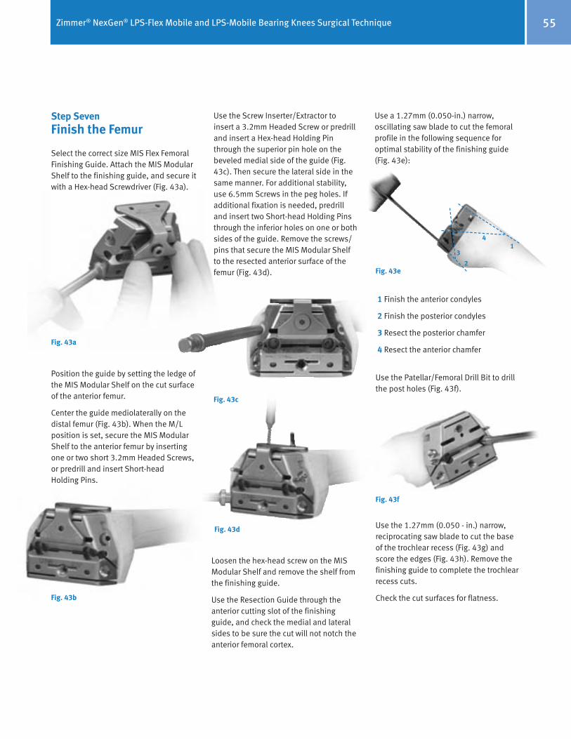
Zimmer® NexGen® LPS-Flex Mobile and LPS-Mobile Bearing Knees Surgical Technique 55
Step SevenFinish the Femur
Select the correct size MIS Flex Femoral Finishing Guide. Attach the MIS Modular Shelf to the finishing guide, and secure it with a Hex-head Screwdriver (Fig. 43a).
Position the guide by setting the ledge of the MIS Modular Shelf on the cut surface of the anterior femur.
Center the guide mediolaterally on the distal femur (Fig. 43b). When the M/L position is set, secure the MIS Modular Shelf to the anterior femur by inserting one or two short 3.2mm Headed Screws, or predrill and insert Short-head Holding Pins.
Fig. 43a
Fig. 43b
Fig. 43c
Fig. 43d
Loosen the hex-head screw on the MIS Modular Shelf and remove the shelf from the finishing guide.
Use the Resection Guide through the anterior cutting slot of the finishing guide, and check the medial and lateral sides to be sure the cut will not notch the anterior femoral cortex.
Use the Screw Inserter/Extractor to insert a 3.2mm Headed Screw or predrill and insert a Hex-head Holding Pin through the superior pin hole on the beveled medial side of the guide (Fig. 43c). Then secure the lateral side in the same manner. For additional stability, use 6.5mm Screws in the peg holes. If additional fixation is needed, predrill and insert two Short-head Holding Pins through the inferior holes on one or both sides of the guide. Remove the screws/pins that secure the MIS Modular Shelf to the resected anterior surface of the femur (Fig. 43d).
Use a 1.27mm (0.050-in.) narrow, oscillating saw blade to cut the femoral profile in the following sequence for optimal stability of the finishing guide (Fig. 43e):
Fig. 43e
14
3
2
1 Finish the anterior condyles
2 Finish the posterior condyles
3 Resect the posterior chamfer
4 Resect the anterior chamfer
Use the Patellar/Femoral Drill Bit to drill the post holes (Fig. 43f).
Fig. 43f
Use the 1.27mm (0.050 - in.) narrow, reciprocating saw blade to cut the base of the trochlear recess (Fig. 43g) and score the edges (Fig. 43h). Remove the finishing guide to complete the trochlear recess cuts.
Check the cut surfaces for flatness.

Zimmer® NexGen® LPS-Flex Mobile and LPS-Mobile Bearing Knees Surgical Technique56
Use a reciprocating saw to cut the sides and base of the intercondylar box (Fig. 43l). Protect the tibia with a wide osteotome.
Use the Patellar/Femoral Drill to drill the femoral post holes.
Then use an oscillating saw to cut the anterior chamfer and the posterior chamfer (Fig. 43m).
Fig. 43m Cut the anterior and posterior chamfers
Option 1MIS Notch/Chamfer Trochlear Guide
The MIS Notch/Chamfer Trochlear Guide consists of two pieces for each size, the MIS Notch/Chamfer Guide and the MIS Trochlear Guide. Matching sizes must be used.
The MIS Notch/Chamfer Trochlear Guide may be used to complete the chamfer cuts, the trochlear groove, and the intercondylar box, as well as to drill the peg holes after the anterior and posterior cuts have been made with the MIS Femoral Finishing Guide.
After the anterior and posterior cuts have been made, check the flexion gap and the extension gap using the MIS Spacer Block. Make the necessary adjustments.
Fig. 43i Position the MIS Notch/Chamfer Guide flush against the femur
Fig. 43k Secure the MIS Notch/Chamfer Guide to the femur
Fig. 43l Cut the sides and base of the intercondylar box
Note: The distal mediolateral profile of the MIS Notch/Chamfer Guides, anterior to the tabs, can be used to position the guide referencing the lateral condyle.
Insert two Short-head Holding Pins or Short Spring Screws through the anterior flange of the guide to secure the guide in position (Fig. 43j).
Knee in 90° flexion
Secure the MIS Notch/Chamfer Guide to the femur distally with two Short Spring Screws or 3.2mm (1/8-inch) Headed Screws. Alternatively, insert two Hex-head Holding Pins (Fig. 43k).
Fig. 43j Insert two Short-head Holding Pins or Short Spring Screws through the anterior flange
Knee in slight flexion
Position the appropriate size MIS Notch/Chamfer Guide onto the femur so it is flush against the resected surfaces both distally and anteriorly. Ensure that no soft tissue or osteophytes interfere with instrument positioning. Position the guide mediolaterally (Fig. 43i).
Fig. 43g
Fig. 43h
Return to Patellar Preparation and Trial Reduction, page. 35.

Zimmer® NexGen® LPS-Flex Mobile and LPS-Mobile Bearing Knees Surgical Technique 57
Protect the tibia. Use a reciprocating saw through the slots in the Trochlear Guide to cut the sides and base of the trochlear groove (Fig. 43p). Remove the Trochlear Guide, and insert an osteotome over the resected tibial surface below the trochlear groove. Then use the reciprocating saw to finish the trochlear cuts.
Remove the MIS Notch/Chamfer Guide.
Fig. 43o MIS Trochlear Guide secured to MIS Notch/Chamfer Guide
Fig. 43p Cut the sides and base of the trochlear groove
Fig. 43n Apply the matching size MIS Trochlear Guide with the holes aligned
Apply the matching size MIS Trochlear Guide to the MIS Notch/Chamfer Guide with the holes in the Trochlear Guide aligned with the threaded holes in the Notch/Chamfer Guide (Fig. 43n). Thread the MIS Threaded Handle through one of the threaded holes to secure the Trochlear Guide to the MIS Notch/Chamfer Guide (Fig. 43o).
Using the MIS Notch/Chamfer Guide to downsize the femurIf there is a need to downsize the femur, the MIS Notch/Chamfer Guide and MIS Trochlear Guide can be used for sizes C-G standard implants and the Notch/Chamfer Guide can be used for all flex sizes.
Select the preferred size Notch/Chamfer Guide and pin it to the distal femur with two Short Spring Screws or 3.2mm (1/8-inch) Headed Screws (48mm length). Alternatively, insert two Hex-Head Holding Pins. Ensure that the guide is seated on the anterior and distal femur. Use a reciprocating saw to recut the sides of the intercondylar box. Use an oscillating saw to recut the anterior and posterior chamfers.
If downsizing for a LPS-Flex Implant, use the posterior surface of the MIS Notch/Chamfer Guide for the posterior cut. If downsizing for a LPS Implant, use the MIS Threaded Handle to attach the matching size MIS Trochlear Guide to the Notch/Chamfer Guide, and use the posterior surface of the MIS Trochlear Guide for the posterior cut.
Remove the MIS Trochlear Guide and MIS Notch/Chamfer Guide.
Return to Patellar Preparation and Trial Reduction, page. 35.

Zimmer® NexGen® LPS-Flex Mobile and LPS-Mobile Bearing Knees Surgical Technique58
Package Insert
NexGen® LPS-Flex Mobile and LPS-Mobile Bearing Knee Systems(United States Version)
Indications • This device is indicated for patients with severe knee pain and disability due to: - Osteoarthritis. - Primary and secondary traumatic arthritis. - Avascular necrosis of the femoral condyle. - Moderate valgus, varus, or flexion deformities (i.e., valgus/varus deformity of ‹ 15°, fixed flexion deformity of ‹ 10°).
• This device is intended for cemented use only.
Contraindications • Contraindications include: - Previous history of infection in the affected joint and/or local/systemic infection that may affect the prosthetic joint. - Insufficient bone stock on femoral or tibial surfaces. - Skeletal immaturity. - Neuropathic arthropathy. - Osteoporosis or any loss of musculature or neuromuscular disease that compromises the affected limb. - A stable, painless arthrodesis in a satisfactory functional position. - Severe instability secondary to the absence of collateral ligament integrity. • Total knee arthroplasty is contraindicated in patients who have rheumatoid arthritis (RA) and an ulcer of the skin or a history of recurrent breakdown of the skin because their risk of postoperative infection is greater. RA patients using steroids may also have increased risk of infection. Late infections in RA patients have been reported 24+ months postoperative.
Warnings • Do not reuse. This device is for single patient use only. • Avoid notching, scratching, or striking the device. Improper preoperative or intraoperative implant handling or damage (e.g., scratches, dents, etc.) can lead to crevice corrosion, fretting, fatigue fracture and/or excessive wear. • Prior to closure of the surgical site, thoroughly cleanse the site of bone chips, bone cement, and any other debris. Foreign particles at the articular interface may cause excessive wear. • Do not use: - This product for other than labeled indications. - Any component, if damage is found or caused during setup or insertion. - Components from other knee systems (and vice versa) unless expressly labeled for such use. Premature wear or loosening may develop and may require surgical explantation. - NexGen CR, CRA or CR-Flex femoral components with LPS-Mobile articular surfaces. They were not designed to be compatible. - The LPS-Mobile articular surfaces with porous LPS-Flex femoral components or porous LPS femoral components as these femoral components are not approved for use with the NexGen LPS Mobile Bearing Knee systems.
- LPS or LPS-Flex femoral components with Prolong® LPS-Mobile articular surfaces unless the part number of the femoral component has a 51 or 52 part number suffix. Use of other suffix LPS and LPS-Flex femoral components may increase the risk of articular surface fracture.
• All LPS-Mobile 17 and 20mm tibial articular surfaces require a locking screw to fasten the articular surface to the Fluted Stem Mobile and MIS LPS-Mobile tibial baseplates. Failure to use the locking screw may result in premature failure of the components
(e.g., separation) due to the greater moment (i.e., forces) acting on these thicker components. • Use only LPS-Mobile tibial articular surfaces with the Fluted Stem Mobile and MIS LPS-Mobile tibial baseplates (and vice versa) as they are not com patible with other components. • Use only NexGen all-polyethylene patellas with these femoral components. Patellas made for other systems may demonstrate excessive wear when used with these femoral components. • Avoid improper positioning and alignment of the implant components. The risk of implant failure is higher with inaccurate component alignment or positioning due to unusual stress conditions which may occur, leading to a reduction in the service life of the implant components. Please refer to the surgical technique manual for information specific to positioning of these implant systems. • Soft tissues should be balanced and components positioning confirmed to minimize edge loading. • Consider venting the femur or tibia. Fat embolism risk is increased with intramedullary instrumentation and/ or cement pressurization. • Release leg tourniquets ten minutes apart in simultaneous bilateral knee surgery, to lessen any lung insult that may occur.

Zimmer® NexGen® LPS-Flex Mobile and LPS-Mobile Bearing Knees Surgical Technique 59
Precautions • LPS-Flex/LPS-Mobile components are sized by matching the femoral component letters and the tibial baseplate component numbers to the articular surface label. Ignore any color codes. A knee implant size matching chart is available to supplement these instructions (See the NexGen Complete Knee Solution Component Matching Flowchart in the surgical technique manual). Mis- matching may result in poor surface contact and could produce pain, decrease wear resistance, produce instability of the implant, or otherwise reduce implant life. • Use only instruments and provisional trials specifically designed for use with these devices to help ensure accurate surgical implantation, soft tissue balancing, and evaluation of knee function. Please refer to the accompanying Surgical Techique Manual. • Thicker polyethylene components may be needed if the patient is young, heavy, and/or physically active. • The potential for deep sepsis can be minimized by using biocontamination controls. Continued surveillance for new or recurrent sources of infection should be continued as long as the device is in place. • The safety and effectiveness of this device has not been established in patients with rheumatoid arthritis, collagen disorders, polyarthritis, or pseudogout; or in patients who need a revision total knee replacement.
Potential Adverse Effects associated with Total Knee Arthroplasty • Loosening of the prosthetic knee components • Fracture/damage of the prosthetic knee components • Removal and/or replacement of the device system or its components • Soft tissue impingement or damage • Dislocation and/or joint instability • Malalignment of the prosthetic knee components • Bone fracture • Nerve damage • Infection • Swelling • Leg length discrepancies • Poor range of motion • Delayed wound healing • Temporary or permanent neuropathies • Pain • Cardiovascular disorders including venous thrombosis, pulmonary embolism or myocardial infarction • Histological reactions resulting in Inflammation • Metal sensitivity • Corrosion of metal components • Excessive wear secondary to damage of mating wear surfaces and/or debris that can initiate osteolysis which may result in loosening of the implant • Death
Potential Adverse Effects associated with the NexGen LPS-Flex Mobile and LPS-Mobile Bearing Knee Systems • Excessive wear secondary to damage of multiple mating wear surfaces that can initiate osteolysis which may result in loosening of the implant • Tibiofemoral bearing disassembly • Tibiofemoral subluxation • Dislocation and/or joint instability • Knee stiffness

Zimmer® NexGen® LPS-Flex Mobile and LPS-Mobile Bearing Knees Surgical Technique60
Adverse Events Reported in the Clinical Study of the NexGen LPS-Flex Mobile Bearing KneeIn this clinical study, 388 knees in 374 patients were implanted with either the treatment NexGen LPS-Flex Mobile Bear-ing Knee (n=201) or the control LPS-Flex Fixed Bearing Knee (n=187). All general postoperative adverse events (e.g., sys-temic, non-device related, etc.) reported during the clinical study on all random-ized procedures performed (i.e., All Ana-lyzable procedures) are listed in Table 1. Numbers are cumulative through the 2-year postoperative study endpoint. A time-course distribution of all local-ized adverse events related to the knee replacement surgey and reported in the clinical study is listed in Table 2.
Postoperatively, only complication rates for knee stiffness requiring manipula-tion differed statistically (Fisher’s exact p = 0.01) between the treatment group (7.0%) and the control group (1.6%).
ADVERSE EVENTS REPORTED IN THE CLINICAL STUDY OF THE NEXGEN LPS-FLEX MOBILE BEARING KNEE
In this clinical study, 388 knees in 374 patients were implanted with either the treatment NexGen LPS-Flex Mobile Bearing Knee (n=201) or the control LPS-Flex Fixed Bearing Knee (n=187). All general postoperative adverse events (e.g., systemic, non-device related, etc.) reported during the clinical study on all randomized procedures performed (i.e., All Analyzable procedures) are listed in Table 1. Numbers are cumulative through the 2-year postoperative study endpoint. A time-course distribution of all localized adverse events related to the knee replacement surgey and reported in the clinical study is listed in Table 2. Postoperatively, only complication rates for knee stiffness requiring manipulation differed statistically (Fisher's exact p = 0.01) between the treatment group (7.0%) and the control group (1.6%).
Table 1. General Postoperative Complication Rates for All Analyzable ProceduresGeneral Postoperative
Complication LPS Flex Mobile
(N=201) Control Device
(N=187) Fisher’s Exact Test P-value
Anemia 17 (8.5%) 9 (4.8%) 0.16
Cardiac Arrhythmia 4 (2.0%) 5 (2.7%) 0.74
Congestive Heart Failure 0 2 (1.1%) 0.23
Death 5 (2.5%) 3 (1.6%) 0.73 Infection (contralateral knee cellulitis, following prostectomy, postop - not specified) 1 (0.5%) 2 (1.1%) 0.61
Hemathrosis 5 (2.5%) 1 (0.5%) 0.22
Ileus 2 (1.0%) 1 (0.5%) >0.99
Myocardial Infarction 2 (1.0%) 0 0.50 Nerve Injury (lumbar spine issues and associated with the surgical procedure) 0 2 (1.1%) 0.23
Pulmonary Embolism 1 (0.5%) 0 >0.99
Respiratory Infection 3 (1.5%) 5 (2.7%) 0.49
Stroke 0 1 (0.5%) 0.48
Urinary Retention 1 (0.5%) 4 (2.1%) 0.20
Urinary Tract Infection 3 (1.5%) 2 (1.1%) >0.99
Other General Complications 221 (73.4%) 197 (70.6%) 0.46 The numbers and rates for general complications were determined independently for each complication type. General complications for bilateral patients were handled on a case level for each individual patient.

Zimmer® NexGen® LPS-Flex Mobile and LPS-Mobile Bearing Knees Surgical Technique 61
Table 2. Time Course Distribution of Knee-Related Postoperative Complications and Overall Knee-Related Complication Rates for All Analyzable Procedures
Preop 6 weeks 6 months 1 year 2 year Knee-Related Postoperative Complication Mobile Control Mobile Control Mobile Control Mobile Control Mobile Control
LPS Flex Mobile (N=201)
Control Device
(N=187)
Fischer’s Exact Test
P-value
Deep Wound Infection < 6 weeks 0 0 0 1 0 0 0 0 0 0 0 1 (0.5%) 0.48
Deep Vein Thrombosis 0 0 10 9 0 1 0 0 0 0 10 (5.0%) 10
(5.3%) >0.99
Delayed Wound Healing 0 0 1 0 0 0 0 0 0 0 1 (0.5%) 0 >0.99
Device Clicking 0 0 2 4 0 2 1 1 1 0 4 (2.0%) 7 (3.7%) 0.37
Dislocation (poly only, relocated spontaneously)
0 0 1 0 0 0 0 0 0 0 1 (0.5%) 0 >0.99
Effusion 0 0 3 7 2 2 4 1 0 3 9 (1.3%) 13 (6.9%) 0.38
Flexion Contracture 0 0 1 4 0 1 0 0 0 0 1 (0.5%) 5 (2.7%) 0.11
Fracture of Femur 0 0 0 1 0 0 0 0 0 0 0 1 (0.5%) 0.48
Fracture of Patella 0 0 1 0 0 0 0 0 0 1 1 (0.5%) 1 (0.5%) >0.99
Hematoma 0 0 1 4 0 1 0 0 0 0 1 (0.5%) 5 (2.7%) 0.11
Heterotopic Ossification-Femur 0 0 0 0 1 0 0 0 0 0 1 (0.5%) 0 >0.99
Nerve Deficit 0 0 0 1 0 0 1 0 0 0 1 (0.5%) 1 (0.5%) >0.99
Nerve Injury (lumbar spine, not related to implant or procedure; peroneal nerve palsy, related to procedure))
0 0 0 1 0 0 0 1 0 0 0 2 (1.1%) 0.23
Patella Clunk 0 0 0 0 0 0 0 0 0 1 0 1 (0.5%) 0.48
Patellofemoral Crepitus 0 0 0 0 0 0 0 2 0 0 0 2 (1.1%) 0.23
Patellofemoral Subluxation 0 0 0 0 1 0 0 1 0 0 1 (0.5%) 1 (0.5%) >0.99
Stiff Knee Resulting in Manipulation (4 were done under anesthesia)
0 0 14 3 0 0 0 0 0 0 14 (7.0%) 3 (1.6%) 0.01
Superficial Infection 0 0 0 4 0 0 0 0 0 0 0 4 (2.1%) 0.05
Tibial Base Plate Loosening 0 0 0 0 0 0 1 0 0 1 1 (0.5%) 1 (0.5%) >0.99
Tibial Pain 0 0 0 0 0 0 0 0 1 0 1 (0.5%) 0 >0.99
Wound Dehiscence 0 0 1 0 0 0 0 0 0 0 1 (0.5%) 0 >0.99
Wound Drainage 0 0 3 3 0 0 0 0 0 0 3 (1.5%) 3 (1.6%) >0.99
Other Knee Related Complications 0 2 30 26 10 15 17 12 8 10 65
(30.1%) 63
(31.7%) 0.75

Zimmer® NexGen® LPS-Flex Mobile and LPS-Mobile Bearing Knees Surgical Technique62
Clinical StudyA prospective clinical study was conducted to evaluate the safety and effectiveness of the NexGen LPS-Flex Mobile Bearing Knee.
Clinical Study DesignThe study was an open, randomized, multi-center, concurrently controlled, non-inferiority clinical trial that com-pared the safety and effectiveness of the NexGen LPS-Flex Mobile Bearing knee system (treatment group) to the non-mobile bearing NexGen LPS-Flex Fixed Bearing Knee (control group) at the 2 year postoperative endpoint. Clinical study endpoints included pain, function, radiographic parameters, device survi-vorship, and complications. The study was conducted at 15 centers and in-cluded 388 procedures in 374 patients. This 388 All Analyzable procedures cohort (i.e., all randomized procedures performed) consisted of 201 cases in the treatment group and 187 cases in the control group.
The study included patients 21-80 years of age presenting with severe knee pain and disability due to degenerative joint disease, including:
• Osteoarthritis • Avascular necrosis of the femoral condyle • Posttraumatic arthritis
Per study protocol, the primary study analysis cohort excluded bilateral cases and rheumatoid arthritis cases. However, a large number of patients (n=82), failed to meet all protocol inclusion criteria (e.g., pain and function assessment of less than 60 points on the Knee Society Score (KSS)), but were enrolled into the study. As a result, the primary analysis cohort used to evaluate study success was based on the “As Treated” patients (i.e., excluded bilateral cases and rheumatoid arthritis cases, and included
protocol inclusion critieria deviations) instead of the “Per-Protocol” patients. The “As Treated” cohort consisted of 341 cases, with 173 in the treatment group and 168 in the control group.
The efficacy of the LPS-Flex Mobile Knee was determined by comparing the survivorship, Knee Society Assessment and Function scores, and selected ra-diographic parameters, of the treatment group to the control group in the primary study cohort.
The safety of the LPS-Flex Mobile Bearing Knee in patients was evaluated by moni-toring the difference in cumulative rates of severe knee related complications and unanticipated adverse device effects (UADE’s) between the treatment group and the control group in the primary study cohort.
Clinical Patient Assessment Each patient was evaluated 6 weeks, 6 months, 12 months and 24 months after surgery which included pain, function, quality of life, and radiographic evalu-ations. At two year intervals thereafter, patients were evaluated until the last patient enrolled completed a two-year follow-up evaluation. An independent radiologist reviewed the 6 week and 24 month radiographs by standardized criteria to eliminate potential variability and bias.
Clinical success is a composite measure of the primary safety and effectiveness endpoints, and was determined sepa-rately for each individual patient. To be considered a clinical success a patient had to meet the success criteria for all five primary study endpoints as noted in Table 3.
Table 3: Success Criteria for Primary Study Endpoints at 2 Years
Primary Clinical Endpoints Success Criteria
Knee Society Assessment (pain) Score Knee Society Assessment (pain) Score ≥ 70
Knee Society Function Score Knee Society Function Score ≥ 70
Adverse Events / Complications Absence of Severe Knee Related AE’s and UADE’s
Radiographic Parameters < 2mm Radiolucencies and < 2mm Implant Position Change
Survivorship / Revision No component/device revision or removal
There were a total of 748 complications reported on the All Analyzable procedures dataset (see Tables 1 and 2). Of these complications, 386 (51.6%) involved the treatment group, and 362 (48.4%) involved the control group. The percentage of cases experiencing at least one postoperative complication was similar between the two study device groups. In the treatment group, there were 154/201 (76.6%) cases experiencing at least one postoperative complication, and in the control group there were 143/183 (76.5%). These rates did not differ statistically between the device groups. Postoperatively, only complication rates for knee stiffness requiring manipulation differed statistically (Fisher's exact p = 0.01) between the treatment group (7.0%) and the control group (1.6%). Otherwise, general and knee related complication rates were similar and did not differ statistically between the device groups.
Results Demographics The primary AsTreated cohort of 341 cases included 199 females (treatment group = 94, control group = 105), and 142 males (treatment group = 79, control group = 63). Preoperative diagnoses consisted of 1 case with avascular necrosis (treatment group), 333 cases with osteoarthritis (treatment group = 168, control group = 165), and 7 cases with post-traumatic arthritis (treatment group = 4, control group = 3). Results suggest that there were no significant differences (p=0.05) between study devices in key baseline, demographic, or operative variables, such as age, gender, operative side, preoperative diagnosis, preoperative KSS pain and function scores, or operating time, specified in the study protocol. At two years, patient follow-up was greater than 95% for both study groups. There were eight deaths for reasons unrelated to the surgery or the device (treatment group = 5, control group = 3). Safety and Effectiveness DataSafety and effectiveness results for the primary As Treated study cohort (i.e., 341 cases - 173 treatment group, 168 control group) at two years post-operatively are provided below. Safety Results Adverse Events The adverse events related to total knee replacement surgery for all procedures performed in the clinical study are listed in Tables 1 and 2.
There were a total of 748 complica-tions reported on the All Analyzable procedures dataset (see Tables 1 and 2). Of these complications, 386 (51.6%) involved the treatment group, and 362 (48.4%) involved the control group.
The percentage of cases experiencing at least one postoperative complica-tion was similar between the two study device groups. In the treatment group, there were 154/201 (76.6%) cases experiencing at least one postoperative complication, and in the control group there were 143/183 (76.5%). These rates did not differ statistically between the device groups.

Zimmer® NexGen® LPS-Flex Mobile and LPS-Mobile Bearing Knees Surgical Technique 63
Postoperatively, only complication rates for knee stiffness requiring manipula-tion differed statistically (Fisher’s exact p = 0.01) between the treatment group (7.0%) and the control group (1.6%). Otherwise, general and knee related complication rates were similar and did not differ statistically between the device groups.
Results
DemographicsThe primary As Treated cohort of 341 cases included 199 females (treatment group = 94, control group = 105), and 142 males (treatment group = 79, con-trol group = 63). Preoperative diagnoses consisted of 1 case with avascular ne-crosis (treatment group), 333 cases with osteoarthritis (treatment group = 168, control group = 165), and 7 cases with post-traumatic arthritis (treatment group = 4, control group = 3).
Results suggest that there were no significant differences (p=0.05) between study devices in key baseline, demo-graphic, or operative variables, such as age, gender, operative side, preoperative diagnosis, preoperative KSS pain and function scores, or operating time, speci-fied in the study protocol.
At two years, patient follow-up was greater than 95% for both study groups. There were eight deaths for reasons unrelated to the surgery or the device (treatment group = 5, control group = 3).
Safety and Effectiveness DataSafety and effectiveness results for the primary As Treated study cohort (i.e., 341 cases - 173 treatment group, 168 control group) at two years post-operatively are provided below.
Safety Results
Adverse EventsThe adverse events related to total knee replacement surgery for all procedures performed in the clinical study are listed in Tables 1 and 2.
Severe Knee Related Complications & Unanticipated Adverse Device EffectsThe results for the primary safety endpoint of severe knee related complications and unanticipated adverse device effects at 2 years, which represent a clinical safety failure, are given in Table 4.
Severe Knee Related Complications & Unanticipated Adverse Device Effects The results for the primary safety endpoint of severe knee related complications and unanticipated adverse device effects at 2 years, which represent a clinical safety failure, are given in Table 4.
Table 4. Primary Safety Endpoint Analysis – Available As Treated Endpoints
Primary Study
Endpoint
LPS Flex Mobile (N=173)
Control Device
(N=168)
Difference (98% CI) π [δ = delta]*
Fisher’s Exact Test p-value^ (Lt tail)
Severe Knee Related Complications & UADEs – N (%)
3/173 (1.7%)
5/168 (3.0%)
-1.2% (-5.1%, 2.6%)
[8.9%] 0.87
* δ is the small, maximum clinically acceptable, pre-specified non-inferiority margin. π The 98% two-sided confidence limit is presented as it provides the 99% one-sided lower (upper) limit when
the upper (lower) bound is ignored, as required to assess non-inferiority. ^ Since the p-value was 0.87, a value which is greater than the alpha (Type I error) level of 1 percent (p=0.01)
pre-specified for the one-sided test of the primary safety endpoint, we can declare the LPS-Flex Mobile Bearing Knee does not differ from the LPS-Flex Fixed Knee with any clinical significance at 2 years.
The results for the primary safety endpoint of cumulative incidence of severe knee related complications and unanticipated adverse device effects demonstrate that the treatment group does not differ with any clinical significance from the control group at the 2 year study endpoint. There were a total of two device revisions reported during this study. There were no unanticipated adverse device effects reported in the study.
The results for the primary safety endpoint of cumulative incidence of severe knee related complications and unanticipated adverse device effects demonstrate that the treatment group does not differ with any clinical significance from the control group at the 2 year study endpoint.
There were a total of two device revisions reported during this study.
There were no unanticipated adverse device effects reported in the study.

Zimmer® NexGen® LPS-Flex Mobile and LPS-Mobile Bearing Knees Surgical Technique64
Efficacy Results The results for the for the individual primary efficacy endpoints of pain, function, radiographic parameters, and survivorship at 2 years are given in Table 5.
Efficacy Results The results for the for the individual primary efficacy endpoints of pain, function, radiographic parameters, and survivorship at 2 years are given in Table 5. Table 5. Primary Efficacy Endpoints Analysis – Available As Treated Endpoints
Primary Study
Endpoint
LPS Flex Mobile (N=173)
Control Device (N=168)
Difference (98% CI) π [δ = delta]*
Fisher’s Exact Test p-value^ (Lt tail)
Knee Society Assessment (pain) Score N Mean (Std Dev) (Min, Max)
165
87.9 (12.89) (49, 100)
165
88.0 (14.10) (37.6, 100)
-0.16 points (-3.64, 3.31) [-5.7 points]
Knee Society Function Score N Mean (Std Dev) (Min, Max)
172
79.7 (22.04) (0, 100)
168
80.5 (20.38) (5, 100)
-0.80 points (-6.2, 4.5)
[-8.2 points]
Radiolucency ≥ 2mm and/or Implant Component Position Change ≥ 2mm % (n/N)
1.2% (2/172)
2.4% (4/164)
1.3% (-4.7%, 2.1%)
[5.7%]
0.901
Revision/Removal of Study Device or Component % (n/N)
0.6% (1/173)
0% (0/168)
0.6% (-0.8%, 1.9%)
[4.1%]
0.512
* δ is the small, maximum clinically acceptable, pre-specified non-inferiority margin. A negative sign was added to the value specified in the clinical protocol to indicate the direction of the limit for interpretation.
π The 98% two-sided confidence limit is presented as it provides the 99% one-sided lower (upper) limit when the upper (lower) bound is ignored as required to assess non-inferiority
1 Since the p-value was 0.90, a value which is greater than the alpha (Type I error) level of 1 percent (0.01) pre-specified for the one-sided test of the primary radiographic endpoint, we can declare the LPS-Flex Mobile Bearing Knee does not differ from the control device with any clinical significance at 2 years.
2 Since the p-value was 0.51, a value which is greater than the alpha (Type I error) level of 1 percent (0.01) pre-specified for the one-sided test of the primary survival endpoint, we can declare the LPS-Flex Mobile Bearing Knee does not differ from the control device with any clinical significance at 2 years.
Knee Society Assessment Scores The results for the primary efficacy endpoint of pain, as measured by the KSS Assessment (pain) Score, demonstrate that the treatment group does not differ with any clinical significance from the control group at the 2 year study endpoint. Knee Society Function Scores The results for the primary efficacy endpoint of function, as measured by the KSS Function Score, demonstrate that the treatment group does not differ with any clinical significance from the control group at the 2 year study endpoint.
64

Zimmer® NexGen® LPS-Flex Mobile and LPS-Mobile Bearing Knees Surgical Technique 65
Knee Society Assessment ScoresThe results for the primary efficacy endpoint of pain, as measured by the KSS Assessment (pain) Score, demon-strate that the treatment group does not differ with any clinical significance from the control group at the 2 year study endpoint.
Knee Society Function ScoresThe results for the primary efficacy endpoint of function, as measured by the KSS Function Score, demonstrate that the treatment group does not differ with any clinical significance from the control group at the 2 year study endpoint.
Radiographic DataThe results for the primary efficacy endpoint of radiographic parameters, as measured by the presence of radiolucency(ies) › 2 millimeters and/or implant component position change › 2 millimeters, which represent radiograph-ic failure, demonstrate that the treatment group does not differ with any clinical significance from the control group at the 2 year study endpoint.
Implant SurvivorshipThe results for the primary efficacy endpoint of implant survivorship, as measured by the cumulative revisions/removals of the device, which represents implant failure, demonstrate that the treatment group does not differ with any clinical significance from the control group in cumulative number of revisions at the 2 year study endpoint.
There were two device revisions reported during this study. One patient (treatment group) was revised with a new femoral component after 21 months, prior to the 2 year study endpoint. One bilateral patient (control group) was revised with a new articular surface after 31 months, subsequent to the 2 year study endpoint, and does not appear in the data tables.
Clinical SuccessTable 6 displays the proportion of patients that met the success criteria for each of the five individual study end-points at 2 years post-operatively.
Radiographic Data The results for the primary efficacy endpoint of radiographic parameters, as measured by the presence of radiolucency(ies) ≥ 2 millimeters and/or implant component position change ≥ 2 millimeters, which represent radiographic failure, demonstrate that the treatment group does not differ with any clinical significance from the control group at the 2 year study endpoint.
Implant Survivorship The results for the primary efficacy endpoint of implant survivorship, as measured by the cumulative revisions/removals of the device, which represents implant failure, demonstrate that the treatment group does not differ with any clinical significance from the control group in cumulative number of revisions at the 2 year study endpoint. There were two device revisions reported during this study. One patient (treatment group) was revised with a new femoral component after 21 months, prior to the 2 year study endpoint. One bilateral patient (control group) was revised with a new articular surface after 31 months, subsequent to the 2 year study endpoint, and does not appear in the data tables.
Clinical Success
Table 6 displays the proportion of patients that met the success criteria for each of the five individual study endpoints at 2 years post-operatively. Table 6: Individual Success Criteria Results at 2 Years
Success Criteria LPS Flex Mobile (N= 173)
Control Device (N=168)
Knee Society assessment (pain) score ≥ 70
92% (152/165)
88% (145/165)
Knee Society function Score ≥ 70 79.7% (137/172)
80.5% (135/168)
Absence of severe knee related AE’s and UADE’s
98.3% (170/173)
97% (163/168)
< 2mm radiolucencies and < 2mm subsidence for all views
98.8% (170/172)
97.6% (160/164)
No component/device removal 99.4% (172/173)
100% (168/168)
A secondary analysis of the composite measure of clinical success was also performed. That is, the proportion of patients from each group that met the success criteria for all five primary study endpoints were compared. Table 7 displays the composite clinical success rates for the treatment group in comparison to the control group. Table 7. Secondary Endpoint Analysis for Clinical Success – Available As Treated Endpoints
Secondary Study
Endpoint
LPS Flex Mobile (N=173)
Control Device (N=168)
Difference (90% CI)
[δ = delta]*
Composite Measure of Achieving Clinical Success – % (n/N)
69.1% (114/165)
67.7%
(109/161)
1.4% (-7.1%, 9.9%)
[10.0%]
* δ is the small, maximum clinically acceptable, pre-specified non-inferiority margin. A negative sign was added to the value specified in the clinical protocol to indicate the direction of the limit for interpretation.
π The 90% two-sided confidence limit is presented as it provides the 95% one-sided upper limit when the lower bound is ignored as required to assess non-inferiority
A secondary analysis of the composite measure of clinical success was also performed. That is, the proportion of patients from each group that met the success criteria for all five primary study endpoints were compared. Table 7 displays the composite clinical success rates for the treatment group in compari-son to the control group.
Radiographic Data The results for the primary efficacy endpoint of radiographic parameters, as measured by the presence of radiolucency(ies) ≥ 2 millimeters and/or implant component position change ≥ 2 millimeters, which represent radiographic failure, demonstrate that the treatment group does not differ with any clinical significance from the control group at the 2 year study endpoint.
Implant Survivorship The results for the primary efficacy endpoint of implant survivorship, as measured by the cumulative revisions/removals of the device, which represents implant failure, demonstrate that the treatment group does not differ with any clinical significance from the control group in cumulative number of revisions at the 2 year study endpoint. There were two device revisions reported during this study. One patient (treatment group) was revised with a new femoral component after 21 months, prior to the 2 year study endpoint. One bilateral patient (control group) was revised with a new articular surface after 31 months, subsequent to the 2 year study endpoint, and does not appear in the data tables.
Clinical Success
Table 6 displays the proportion of patients that met the success criteria for each of the five individual study endpoints at 2 years post-operatively. Table 6: Individual Success Criteria Results at 2 Years
Success Criteria LPS Flex Mobile (N= 173)
Control Device (N=168)
Knee Society assessment (pain) score ≥ 70
92% (152/165)
88% (145/165)
Knee Society function Score ≥ 70 79.7% (137/172)
80.5% (135/168)
Absence of severe knee related AE’s and UADE’s
98.3% (170/173)
97% (163/168)
< 2mm radiolucencies and < 2mm subsidence for all views
98.8% (170/172)
97.6% (160/164)
No component/device removal 99.4% (172/173)
100% (168/168)
A secondary analysis of the composite measure of clinical success was also performed. That is, the proportion of patients from each group that met the success criteria for all five primary study endpoints were compared. Table 7 displays the composite clinical success rates for the treatment group in comparison to the control group. Table 7. Secondary Endpoint Analysis for Clinical Success – Available As Treated Endpoints
Secondary Study
Endpoint
LPS Flex Mobile (N=173)
Control Device (N=168)
Difference (90% CI)
[δ = delta]*
Composite Measure of Achieving Clinical Success – % (n/N)
69.1% (114/165)
67.7%
(109/161)
1.4% (-7.1%, 9.9%)
[10.0%]
* δ is the small, maximum clinically acceptable, pre-specified non-inferiority margin. A negative sign was added to the value specified in the clinical protocol to indicate the direction of the limit for interpretation.
π The 90% two-sided confidence limit is presented as it provides the 95% one-sided upper limit when the lower bound is ignored as required to assess non-inferiority
The results demonstrate that the treat-ment group does not differ with any clinical significance from the control group in terms of the composite measure of clinical success.
Zimmer NexGen LPS-Flex Mobile and LPS-Mobile Bearing Knees Surgical Technique

97-5964-302-00 Rev. 2 1011-K28 .5ML Printed in USA ©2007, 2009, 2010 Zimmer, Inc.
This documentation is intended exclusively for physicians and is not intended for laypersons.Information on the products and procedures contained in this document is of a general nature and does not represent and does not constitute medical advice or recommendations. Because this information does not purport to constitute any diagnostic or therapeutic statement with regard to any individual medical case, each patient must be examined and advised individually, and this document does not replace the need for such examination and/or advice in whole or in part. Please refer to the package inserts for important product information, including, but not limited to, contraindications, warnings, precautions, and adverse effects.
Contact your Zimmer representative or visit us at www.zimmer.com
+H124975964302001/$101206R2L10-


![[Title to come] · 2021. 1. 25. · The image part with relationship ID rId5 was not found in the file. [Title to come] [Sub-Title to come] Date Strictly for Intended Recipients Only](https://img.pdfslide.net/doc/110x75/61273377ca318300cb1060d7/title-to-come-2021-1-25-the-image-part-with-relationship-id-rid5-was-not.jpg)


![IEEE TRANSACTIONS ON IMAGE PROCESSING, VOL. 23 ......X come from external image databases [12]–[14], which we refer to as external denoising. For example, 15,000 images (corresponding](https://img.pdfslide.net/doc/110x75/602865d9cb9031287a45dc78/ieee-transactions-on-image-processing-vol-23-x-come-from-external-image.jpg)


![TuiGAN: Learning Versatile Image-to-Image Translation with ... · 2.1 Image-to-Image Translation The earliest concept of image-to-image translation (I2I) may be raised in [11] which](https://img.pdfslide.net/doc/110x75/5f6c048fda117a573c714a09/tuigan-learning-versatile-image-to-image-translation-with-21-image-to-image.jpg)


![Chapter 1 Context, theory, design come here] 1 [Cover image to Context, theory, design come here] The South African school context Th e country has made signifi cant progress towards](https://img.pdfslide.net/doc/110x75/5abb5eeb7f8b9a76038ca14c/chapter-1-context-theory-design-come-here-1-cover-image-to-context-theory.jpg)