Embed Size (px)
Citation preview

Imaging freeform optical systems designed with NURBS surfaces
The MIT Faculty has made this article openly available. Please share how this access benefits you. Your story matters.
Citation Chrisp, Michael P., Brian Primeau, and Michael A. Echter. “ImagingFreeform Optical Systems Designed with NURBS Surfaces.” OpticalEngineering 55.7 (2016): 71208.
As Published http://dx.doi.org/10.1117/1.OE.55.7.071208
Publisher SPIE
Version Final published version
Citable link http://hdl.handle.net/1721.1/105221
Terms of Use Article is made available in accordance with the publisher'spolicy and may be subject to US copyright law. Please refer to thepublisher's site for terms of use.

Imaging freeform optical systemsdesigned with NURBS surfaces
Michael P. ChrispBrian PrimeauMichael A. Echter
Michael P. Chrisp, Brian Primeau, Michael A. Echter, “Imaging freeform optical systems designed withNURBS surfaces,” Opt. Eng. 55(7), 071208 (2016), doi: 10.1117/1.OE.55.7.071208.
Downloaded From: http://opticalengineering.spiedigitallibrary.org/ on 10/06/2016 Terms of Use: http://spiedigitallibrary.org/ss/termsofuse.aspx

Imaging freeform optical systems designed with NURBSsurfaces
Michael P. Chrisp,a,* Brian Primeau,a and Michael A. Echtera,baMassachusetts Institute of Technology Lincoln Laboratory, 244 Wood Street, Lexington, Massachusetts 02420, United StatesbUniversity of Rochester, Department of Mechanical Engineering, 235 Hopeman Building, Rochester, New York 14627-0132, United States
Abstract. The designs of two imaging freeform systems using nonuniform rational basis-spline (NURBS) opticalsurfaces are described. The first system, a 10 deg×9 deg f∕2 three-mirror anastigmat has four times higherspatial resolution over the image plane compared with the equivalent conventional rotational aspheric design,and 2.5 times higher resolution compared with a 10th-order XY polynomial freeform design. The mirrors forthe NURBS freeform design have more than twice the asphericity than the conventional rotational and XY poly-nomial designs. In the second system, a Ritchey–Chretien telescope followed by a two-mirror NURBS freeformcorrector is compared to a four-mirror Korsch telescope, for imaging to a visible-infrared imaging spectrometer.The freeform corrector design had 70% smaller spot sizes over the field and eliminated the large tertiary requiredin Korsch type design. Both of these NURBS freeform designs are possible due to a custom optical design codefor fast accurate NURBS optimization, which now has parallel raytracing for thousands of NURBS grid points.© The Authors. Published by SPIE under a Creative Commons Attribution 3.0 Unported License. Distribution or reproduction of this work in whole orin part requires full attribution of the original publication, including its DOI. [DOI: 10.1117/1.OE.55.7.071208]
Keywords: optical design; aspherics; nonuniform rational basis-spline; splines; geometrical design; optimization; reflective;anastigmat; NURBS.
Paper 151862SS received Dec. 31, 2015; accepted for publication Jul. 13, 2016; published online Aug. 1, 2016.
1 IntroductionThe imaging freeform optical systems described here aredesigned using nonuniform rational basis-spline (NURBS)surfaces. Although NURBS surfaces have been widelyused for illumination systems, efforts to optimize them inimaging systems have so far been largely unsuccessful; asa consequence, the optical design community has consideredthem unsuitable for these systems.1 The major optical designprograms CODEV,2 Zemax,3 and FRED4 are not capable ofoptimizing NURBS grid-type ðu; vÞ surfaces in imaging sys-tems, a necessary step in freeform optics design.
There is no problem with raytracing NURBS grid-typesurfaces, which can be accomplished in LightTools,2
FRED,4 and by Zeiss5 with their in-house code; but to suc-ceed in designing NURBS freeform optical systems, an opti-mization code is required.
The motivation for developing the optical design code forfast accurate NURBS optimization (FANO6,7) is based on themathematical properties of NURBS surfaces, which makethem well-suited for representing freeform optical surfaces.The most important property of an NURBS surface is thelocal control of the surface shape, because it is formed frompiecewise splines. Figure 1 shows a third-degree NURBSsurface that is formed from cubic basis splines. The surfaceis defined by the set of grid control points with their weights,together with the knot vectors. Rays 1 and 2 are affected onlyby the grid control points in their respective shaded sections,because only the 16 closest grid control points affect the sur-face shape at the ray intersection. To change the direction of
ray 1, its 16 grid control points can be moved, leaving theray 2 unchanged.
This local control is important for complex surfaces,which must be represented by thousands of grid controlpoints since each ray is still affected only by its local 16grid control points. A consequence of this is that the matricesbuilt from the control point variables are better conditionedfor solving in the optimization.
This local ray control contrasts with a polynomial surface,where all the polynomial terms globally affect every point onthe surface. As such, moving ray 1 in the example wouldrequire rebalancing all polynomial terms to leave the ray2 pointing in the same direction.
NURBS surfaces also have a number of advantageousproperties including the ability to perfectly represent planeand quadric surfaces, with mathematical details covered byPiegl and Tiller.8 Compare this with Gaussian basis func-tions, with which it is challenging to provide smoothplane and quadric surfaces.9
2 Fast Accurate Nonuniform Rational Basis-SplineOptimization Design Code
The FANO design code has a fast raytrace engine using opti-mization algorithms, designed for NURBS surfaces, with thenumerical accuracy for large numbers of variables and rays.Parallelizing using OpenGL enabled its speed to be increasedby up to a factor of 8 over the first generation, enablingthe freeform designs, which use 5000 grid point variablesand 50,000 rays. FANO is written in C for portability anduses the Intel Math Kernel library for manipulation of thelarge matrices. Although capable of supporting differentdegree surfaces, all the results shown in this study are withthird-degree NURBS freeform surfaces. Given the largenumbers of rays, FANO was designed from the outset for
*Address all correspondence to: Michael P. Chrisp, E-mail: [email protected]
Optical Engineering 071208-1 July 2016 • Vol. 55(7)
Optical Engineering 55(7), 071208 (July 2016)
Downloaded From: http://opticalengineering.spiedigitallibrary.org/ on 10/06/2016 Terms of Use: http://spiedigitallibrary.org/ss/termsofuse.aspx

a fast raytrace speed. It can trace 10 million NURBS ray sur-faces/s—4000 times faster than the commercial illuminationcode against which it was compared.
FANO avoids the limitations found in current opticaldesign codes for even simple rotational NURBS surfa-ces,10,11 perhaps because commercial codes are designedto optimize standard optical systems with much smallernumbers of variables and rays, and with algorithms writtenfor speed rather than precision. No success has been reportedwith any of the current optical design codes in optimizingimaging systems with NURBS freeform surfaces, pro-grammed into their code.
FANO’s structure and communication with other pro-grams are shown in Fig. 2. From CODEV, simple startingdesigns can be imported in the form of point clouds,which are converted to NURBS surfaces. Typically, a regu-larly spaced NURBS grid is used with the parameterizationfor the two knot vectors based on the average chord lengthsover the surface. There is no export to CODEV since itcannot raytrace NURBS grid surfaces.
FRED can raytrace NURBS surfaces, so that the fileexchange takes place in two directions. FRED scripts enablethe export of the NURBS surfaces and geometry to FANO,which directly reads in the NURBS parameters with no con-version necessary. In a similar manner, FANO can write thesame file format to FRED, which is used to confirm all analy-sis results and to display the resulting designs, such as thefigures in this paper. FRED does have a simplex optimiza-tion, which is very limited and not suitable for large NURBSoptimization problems.
The final software package DIFFSYS12 is used for con-trolling Lincoln Laboratory’s diamond-turning machine,a Moore Nanotech 350FG,13 which can directly diamond-turn freeform surfaces. A subroutine in FANO exportsa point cloud in the correct format for import into theDIFFSYS software. DIFFSYS takes the point cloud andfits a surface to the points that the diamond tool will follow.One nice feature of DIFFSYS is that the sagittal position ofany point on the interpolated surface can be output, enablingthe error to be calculated from the original NURBS surface.Currently, the diamond-turning machines by Moore13 andPrecitech14 cannot accept direct NURBS input; however,Schneider optical machines15 freeform diamond-turningmachine UPC 400 can accept NURBS surfaces directly.
3 Freeform f ∕2 Three-Mirror Anastigmat DesignThe following designs show the performance improvementmade by using NURBS freeform surfaces in an f∕2 three-mirror anastigmat design, with the design parameters givenin Table 1. For comparison, three designs meeting the opticalrequirements have been created with the stop at the secon-dary. The conventional aspheric design is optimized inCODEV and uses tilted and decentered rotational asphericsurfaces with aspheric terms up to the 14th power. TheXY polynomial design is optimized in CODEV and usesthe relevant aspheric terms, including the odd powers aswell, up to the 10th power. The NURBS freeform designis optimized by FANO with grids of 37 × 37 for the mirrorM1, 29 × 29 for mirror M2, and 41 × 41 for mirror M3. Noconstraints were placed on any of the aspheric terms as wellas the NURBS grid points.
The three designs are shown to the same scale in Fig. 3.The same package volume was available to all design forms,implemented by letting the spaces vary, with just outerbounds on the chief ray distances between the mirrors andray clearances controlling the mirror angles. Although thespacings between the mirrors in the NURBS design arelarger, forcing the conventional and XY polynomial freeformdesigns to match those spacings reduced their performance.During optimization the average geometric rms spot size isused as the merit function.
The stop size was left as a variable during optimization yetset to coincide with the secondary mirror. The NURBS free-form design is optimized and analyzed in FANO, while usingFRED for confirmation of the analysis and to display thedesign. Comparing the layouts, the NURBS design has betterclearance to the focal plane.
In Fig. 4, the rms spot sizes are mapped out over the fieldof view, showing the improved performance with theNURBS freeform surfaces. The average rms spot size for
Ray 2Ray 1
Fig. 1 Rays reflecting from third-degree NURBS surface.
Fig. 2 FANO program.
Table 1 Three-mirror anastigmat design parameters.
Parameter Requirement
Field of view 10 deg×9 deg
Entrance pupil 18 × 18 cm2
Focal length 35.7 cm
f -number 2
Optical Engineering 071208-2 July 2016 • Vol. 55(7)
Chrisp, Primeau, and Echter: Imaging freeform optical systems designed with NURBS surfaces
Downloaded From: http://opticalengineering.spiedigitallibrary.org/ on 10/06/2016 Terms of Use: http://spiedigitallibrary.org/ss/termsofuse.aspx

the conventional aspheric design is 61 μm; for the XY poly-nomial design 36 μm; and for the NURBS design it is14 μm, a factor of 2.5 better than the XY polynomial design.The NURBS design also has less variation in the rms spotsize over the field of view.
The modulation transfer function (MTF) curves at thecenter of the field are shown in Fig. 5, calculated at a wave-length of 3 μm. The curves are the average of the twoorthogonal directions at the detector. At 50 cycles∕mm,
the NURBS freeform system has the highest MTF at0.55, with the XY polynomial freeform system having anMTF of 0.05 and the conventional system MTF of 0.15.Although the conventional system and the XY polynomialfreeform systems have similar geometric spot sizes at thecenter, the higher MTF of the conventional system is dueto a high MTF perpendicular to the symmetry plane. Thesmoothness of the NURBS MTF shows that the spline sur-face is smooth over this spatial frequency range.
3.1 Mirror Aspheric Shapes
Given the significant performance difference between theNURBS freeform design and the conventional asphericdesign, and the XY polynomial freeform design, then thequestion is how the aspheric shapes differ. This is analyzedby subtracting the best-fit sphere from each surface and map-ping out the aspheric deviation of the surfaces from the best-fit sphere. Figure 6 illustrates the aspheric departure shapesfor the mirrors in the three designs.
Some interesting differences between the mirror shapescan be seen. For NURBS freeform design, all the mirrorsare astigmatic with little coma present. For the secondarymirror M2, the correction for the rotational aspheric designand the XY polynomial design is much less than that ofNURBS design.
The power of the aspherics can be assessed from theaverage rms aspheric deviations from their best-fit spheres,
(a) (b) (c)
Fig. 3 Three-mirror anastigmat f∕2 designs: (a) conventional rotational aspheres design, (b) XY poly-nomial freeform design, and (c) NURBS freeform design.
Fig. 4 Field map of rms spot sizes for f∕2 three-mirror anastigmat designs: (a) conventional rotationalaspheres design, (b) XY polynomial freeform design, and (c) NURBS freeform design.
Fig. 5 MTF comparison between designs.
Optical Engineering 071208-3 July 2016 • Vol. 55(7)
Chrisp, Primeau, and Echter: Imaging freeform optical systems designed with NURBS surfaces
Downloaded From: http://opticalengineering.spiedigitallibrary.org/ on 10/06/2016 Terms of Use: http://spiedigitallibrary.org/ss/termsofuse.aspx
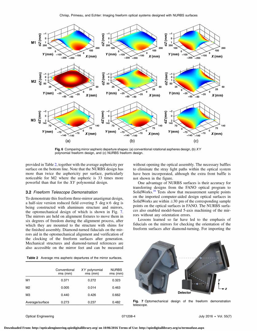
provided in Table 2, together with the average asphericity persurface on the bottom line. Note that the NURBS design hasmore than twice the asphericity per surface, particularlynoticeable for M2 where the aspheric is 33 times morepowerful than that for the XY polynomial design.
3.2 Freeform Telescope Demonstration
To demonstrate this freeform three-mirror anastigmat design,a half-size version reduced field covering 5 deg× 6 deg isbeing constructed with aluminum structure and mirrors,the optomechanical design of which is shown in Fig. 7.The mirrors are held on alignment fixtures to move them insix degrees of freedom during the alignment process, afterwhich they are mounted to the structure with shims forthe finished assembly. Diamond-turned fiducials on the mir-rors aid in the optomechanical alignment and verification ofthe clocking of the freeform surfaces after generation.Mechanical structures and diamond-turned references arealso accessible on the mirror feet and can be measured
without opening the optical assembly. The necessary bafflesto eliminate the stray light paths within the optical systemhave been incorporated, although the extra front baffle isnot shown in the figure.
One advantage of NURBS surfaces is their accuracy fortransferring designs from the FANO optical program toSolidWorks.16 Tests show that measurement sample pointson the imported computer-aided design optical surfaces inSolidWorks are within �30 pm of the corresponding samplepoints on the optical surfaces in FANO. The NURBS surfa-ces also enabled model-based 5-axis machining of the mir-rors without any orientation errors.
Lessons learned so far have led to the emphasis offiducials on the mirrors for checking the orientation of thefreeform surfaces after diamond-turning. For importing the
Fig. 6 Comparing mirror aspheric departure shapes: (a) conventional rotational aspheres design, (b) XYpolynomial freeform design, and (c) NURBS freeform design.
Table 2 Average rms aspheric departures of the mirror surfaces.
Conventionalrms (mm)
XY polynomialrms (mm)
NURBSrms (mm)
M1 0.371 0.272 0.323
M2 0.005 0.014 0.463
M3 0.440 0.426 0.662
Average/surface 0.273 0.237 0.482
Detectorz
y
Fig. 7 Optomechanical design of the freeform demonstrationtelescope.
Optical Engineering 071208-4 July 2016 • Vol. 55(7)
Chrisp, Primeau, and Echter: Imaging freeform optical systems designed with NURBS surfaces
Downloaded From: http://opticalengineering.spiedigitallibrary.org/ on 10/06/2016 Terms of Use: http://spiedigitallibrary.org/ss/termsofuse.aspx

design into SolidWorks, it was found best to import eachNURBS surface separately into an optical assembly file sothat the local coordinate systems for the grid points were thesame among the FANO, FRED, and SolidWorks models. Forthe diamond-turning only, being able to import point cloudsleaves the process open to error since the visualization showsjust the surface without the rest of the mirror structure. It isvery easy to end up with the freeform surface improperlyclocked on the part if not verified.
For the hardware, the optical bench is assembled with theinitial diamond-turned bare aluminum mirrors, as shown inFig. 8. The mirrors are checked by the use of computer-generated holograms (CGH), which help to identify anysignificant errors such as clocking or improper machineprogramming of the freeform surfaces. Initial tests of thecompleted assembly show the expected performance, giventhe figure errors of a few waves on the diamond-turned sur-faces. The mirrors have been electroless nickel-plated andfigured using magnetorheological finishing (MRF) at QEDCorporation,17 based on the measurements using the CGHand subaperture stitching interferometry. These mirrors arecurrently being aligned in the final assembly, using interfer-ometry and computer-aided alignment techniques.
3.3 Alignment Sensitivity Comparison
An initial tolerance sensitivity, performed on both NURBSfreeform and the conventional rotational aspheric designsfor a narrower 5 × 6 deg field of view, established thedifficulty of aligning the higher resolution freeform design.The results shown in Table 3 give the change in the averagerms spot size over the field for the mirror translations,according to the coordinate axes drawn in Fig. 7.
Each mirror is moved with a local shift, leaving the globalcoordinates of the other mirrors in the same place. The detec-tor plane is used as a compensator, with its longitudinalz-position, and two tilts optimized to minimize the effectof the aberrations for each movement. For the freeform sys-tem, the decentrations of mirrors M2 and M3 introduce thelargest changes in the spot size.
The root-sum-squared (RSS) of the individual aberrationsgives their cumulative change of the rms average spot size.Adding this change to the nominal design performance(found at the bottom of the table) leads to the expected per-formance, if the mirror translations match the 0.010-mm
displacement. The increase in the rms spot size for the free-form design is a 16% increase, compared with an increase of0.7% for the conventional aspheric design, showing that tighttolerances are required by the higher resolution freeformdesign.
4 Freeform Correction of an f ∕3 Ritchey–ChretienTelescope
This design demonstrates the way that freeform mirrors pro-vide design form solutions, when introduced into opticaldesigns. The requirement for the design was to feed an im-aging spectrometer slit at the focal plane of an f∕3 telescopewith a telecentric beam matching the 10-μm spectrometerpixels, with the requirements given in Table 4. Given thewide wavelength range of visible through infrared, an all-reflective approach was required.
Fig. 8 Freeform demonstration telescope.
Table 3 Alignment tolerance comparison.
Change in rms spot size (mm)
Shift Value (mm) Conventional Freeform
M1 X 0.01 1.721 × 10−05 1.102 × 10−05
Y 0.01 7.031 × 10−05 3.642 × 10−06
Z 0.01 6.113 × 10−05 8.234 × 10−07
M2 X 0.01 5.328 × 10−06 1.717 × 10−04
Y 0.01 5.573 × 10−05 4.093 × 10−04
Z 0.01 9.119 × 10−05 4.855 × 10−05
M3 X 0.01 2.693 × 10−05 2.582 × 10−04
Y 0.01 1.439 × 10−04 3.741 × 10−04
Z 0.01 9.893 × 10−05 1.030 × 10−05
RSS 0.0002 0.0006
rms spot size (mm)
Nominal design 0.0253 0.0043
Design with alignmenttolerances
0.0255 0.0050
Table 4 Telescope design parameters.
Parameter Requirement
Entrance pupil diameter 60 cm
f -number 3.0
Focal length 180 cm
Slit field of view 2 deg cross track
Slit image length ∼60 mm
Exit pupil Telecentric
Wavelength range 400 to 5000 nm
Optical Engineering 071208-5 July 2016 • Vol. 55(7)
Chrisp, Primeau, and Echter: Imaging freeform optical systems designed with NURBS surfaces
Downloaded From: http://opticalengineering.spiedigitallibrary.org/ on 10/06/2016 Terms of Use: http://spiedigitallibrary.org/ss/termsofuse.aspx

The traditional design solution based on a variant of athree-mirror Korsch type telescope is given in Fig. 9(a).To make the telescope telecentric, a quaternary mirror wasintroduced after the tertiary, and all four mirrors were opti-mized together using rotational aspheres to the 16th order.There is very little clearance for the spectrometer entranceslit, which is a difficulty with the design.
The freeform solution is shown in Fig. 9(b); here, two free-form mirror correctors are used after a Ritchey–Chretien(RC) telescope, flattening and widening the field of viewfor use with the imaging spectrometer. The large primaryand secondary mirrors are fabricated by traditional fabricationtechniques. However, the small size of the freeform correctorsfacilitates their manufacturing utilizing MRF processes. Thetwo mirrors provide a large amount of correction, reducingthe uncorrected telescope spot sizes of 380 μm by a factorof 35 and providing a telecentric exit pupil.
This two-mirror freeform corrector is close to the detectorand the movement of the small beam footprints over them
leverages the power of flexible freeform surfaces, where rap-idly changing aberrations across the field can be correctedvia complex aspheric surfaces. The mirrors shapes fromoptimizing the NURBS freeform design shown are shownin Fig. 10, where M3 is based on 25 × 25 grid points andM4 on 21 × 35 grid points. The mirrors appear to looklike cylinders, but the aspheric deviations from best-fitspheres show the complexity of the aspheric shape, withlarge aspheric peak to valley departures of 0.8 mm forM3 and 1.2 mm for M4.
The performance of the two designs is shown in compari-son in Fig. 11, where the spot diameters are plotted with fieldalong the spectrometer entrance slit. The Korsch four-mirrorvariant has an average spot size of 16 μm whereas the RCtelescope with the two-mirror NURBS freeform correctorhas an average rms spot diameter of 11 μm. So the freeformdesign has reduced the spot sizes by 70% and has alsoeliminated the large tertiary mirror, saving its weight andstructure and freeing up payload volume.
Tertiary
(a) (b)
QuaternaryFreeform M3
Freeform M4
Slit plane
Fig. 9 Telescopes for spectrometer: (a) four-mirror Korsch design and (b) RC telescope with a two-mirrorfreeform corrector.
Fig. 10 Freeform corrector mirrors: (a) physical shapes and (b) aspheric departures from best-fit sphere.
Optical Engineering 071208-6 July 2016 • Vol. 55(7)
Chrisp, Primeau, and Echter: Imaging freeform optical systems designed with NURBS surfaces
Downloaded From: http://opticalengineering.spiedigitallibrary.org/ on 10/06/2016 Terms of Use: http://spiedigitallibrary.org/ss/termsofuse.aspx

5 ConclusionThe two imaging freeform designs show the performanceadvantages of using NURBS mirror surfaces. For the f∕210 deg×9 deg three-mirror anastigmat, the spatial resolu-tion improves by a factor of 4 compared with a conventional16th-order aspheric design and factor of 2.5, compared witha 10th-order XY polynomial freeform design. The improve-ment was enabled by using the 4000 grid points in theNURBS freeform design, which resulted in different mirrorshapes. The fabrication of a three-mirror anastigmat tele-scope incorporating these surfaces is described.
For the 2-deg slit field f∕3 imaging spectrometer tele-scope, the RC telescope with the two-mirror freeform correc-tor reduced the spot sizes by 70% over the field comparedwith a four-mirror Korsch telescope, and eliminated the largetertiary. This all-reflective corrector design illustrates howflexible NURBS surfaces can correct rapidly changing aber-rations across the focal plane for large telescope systems.
As freeform surfaces increase in aspheric complexity,NURBS surfaces provide the way forward in freeform designdue to their local surface control and their ease of optimiza-tion with thousands of grid control points, demonstrated bythese designs.
AcknowledgmentsThe authors would like to thank Vicky Gauthier, ChristopherSemisch, and Kristin Clark for their support of this work andfor the funding provided through the Technology Office.Supporting the demonstration telescope engineering wereDmitry Tolpin for diamond turning, Alan Akerstrom forfabrication, and Lawrence Petrilli and Amanda Smith. Thispaper is based upon the work supported under Air ForceContract Nos. FA8721-05-C-0002 and/or FA8702-15-D-0001.Any opinions, findings, conclusions, or recommendations
expressed in this paper are those of the author(s) and donot necessarily reflect the views of the U.S. Air Force.
References
1. K. Thompson and J. Rolland, “Freeform optical surfaces,” Opt.Photonics News 23(6), 30–35 (2012).
2. “CODEV and LightTools are by Synopsys,” www.optics.synopsys.com.
3. “Zemax is by Radiant Zemax,” www.zemax.com.4. “FRED is by Photon Engineering,” www.photonengr.com.5. P. Jester, C. Menke, and K. Urban, “B-spline representation of optical
surfaces and its accuracy in a ray trace algorithm,” Appl. Opt. 50, 822–828 (2011).
6. M. P. Chrisp, “New freeform NURBS imaging design code,” Proc.SPIE 9293, 92930N (2014).
7. M. Chrisp, “Method and system for optimizing NURBS surfaces for animaging system,” U.S. Patent Application No. 15/051,787.
8. L. Piegl and W. Tiller, The NURBS Book, 2nd ed., Springer-Verlag,Berlin, Heidelberg (1997).
9. O. Cakmakcil et al., “Meshfree approximation methods for free-formsurface representation in optical design with applications to head-worndisplays,” Proc. SPIE 7061, 70610D (2008).
10. H. Chase, “Optical design with rotationally symmetric NURBS,” Proc.SPIE 4832, 10 (2002).
11. J. Werner et al., “An optimization method for radial NURBS surfaces,”in Deutschen Gesellschaft für Angewandte Optik Proc. (2013).
12. “DIFFSYS Software,” Western Isle Ltd., North Wales, Great Britain,www.westernisle.com.
13. “Moore Nanotechnology Systems,” LLC, Swanzey, New Hampshire,www.nanotechsys.com.
14. “Precitech Corporation,” Keene, New Hampshire, www.precitech.com.
15. “Schneider optical machines,” Fronhausen, Germany, www.schneider-om.com.
16. Solidworks 3DCAD is from Solidworks, Waltham, Massachusetts.17. “QED Technologies,” Rochester, New York, www.qedmrf.com.
Michael P. Chrisp received his MSc and PhD degrees in optics andphysics from London University. He is a senior staff member atMassachusetts Institute of Technology (MIT) Lincoln Laboratory.He is the author of twenty papers, ten patents, and one book chapter.His current research interests include the optical design of spaceimaging systems, imaging spectrometers, and nonuniform rationalbasis-spline freeform optics. He is a member of SPIE.
Brian Primeau received his PhD in optical sciences from theUniversity of Arizona in 2011. He is now at Ball Aerospace and carriedout the work described here while at MIT Lincoln Laboratory. Hiscurrent research interests include optical metrology, tolerancing,alignment, and system design including freeform optics. He is amember of SPIE.
Michael A. Echter is an associate staff member at MIT LincolnLaboratory and is concurrently pursuing his PhD in mechanical engi-neering through the University of Rochester, where he also receivedhis MS and BS degrees. His current research interests include theoptomechanical design of freeform optical systems, space-basedimaging telescopes, and precision deployable telescopes. He is astudent member of SPIE.
Fig. 11 rms spot diameters over the field of view.
Optical Engineering 071208-7 July 2016 • Vol. 55(7)
Chrisp, Primeau, and Echter: Imaging freeform optical systems designed with NURBS surfaces
Downloaded From: http://opticalengineering.spiedigitallibrary.org/ on 10/06/2016 Terms of Use: http://spiedigitallibrary.org/ss/termsofuse.aspx