Embed Size (px)
Citation preview

Intelimet Advantage
1
Copyright 2011, Dynamax Inc
All Rights Reserved
This manual refers to Lascano-Van Bavel ETP computation algorithm, implementation of the algorithm in Intelimet Advantage weather station, including PC200 data logger support software for Intelimet Advantage Weather station. Specifications are subject to change. Dynagage is a new product for experimental purposes under development. DYNAMAX Inc assumes no liability for customer assistance, infringements of patents or copyrights arising from the use of this product. US Patents covering the construction of various stem flow gauges are No 5,337,604 and 5,269,183. DYNAMAX does not warrant or represent that any license, either express or implied, is granted under any patent right, copyright, or other intellectual property right of DYNAMAX relating to this product, or process. There are no implied warranties of merchantability or of fitness for a particular purpose given with the sale of any goods. DYNAMAX Inc shall not be liable for consequential, incidental or special charges. Intelimet Advantage, Dynagage, Dynamet, Flow32, Flow32W are trade marks of Dynamax Inc Lascano-VanBavel ET algorithm as well as CR1000 (Dynamet) and CR200 (Intelimet Advantage) programs for ETP are copyrights of Dynamax Inc. MetPak ll is a trademark of Gill Instruments. IBM is a registered trademark of International Business Machines PC208W PC400, PC200 and LoggerNet are trademarks of Campbell Scientific Inc Windows 2000, Windows XP, Windows Vista, Windows 7, Microsoft Office, Microsoft Excel are trademarks of Microsoft Corporation.
Updated: 04/13/2011

Dynamax Inc
2
Intelimet Advantage
3
Includes documentation for Lascano-van Bavel RCM ET computation algorithm. Programs written and algorithms verified by
Dr. Robert J. Lascano Dr. Cornelius van Bavel, Michael van Bavel, BSEE Sai P. Gonuguntla, MSEE Yunpeng Ji, BSEE
Programs and algorithms Copyright © Dynamax Inc. 2011 Portions of the manual are courtesy of Campbell Scientific, Inc and are subject to Copyright © 1998, Campbell Scientific, Inc. Portions of the manual are courtesy of Gill Instruments and are subject to Copyright © Gill Instruments 2010
Trademarks used are property of their respective owners.
SC32B

Dynamax Inc
4
Intelimet Advantage
5
TABLE OF CONTENTS
1.0 INTRODUCTION TO INTELIMET ADVANTAGE ......................................................................7
1.1 Unpacking, Bill of materials........................................................................................................8 1.1.1 Bill of materials......................................................................................................................9
1.1.2 List of Tools required...........................................................................................................10
1.2 Communication Options............................................................................................................11
2.0 SOFTWARE INSTALLATION......................................................................................................12
2.1 PC200 Installation......................................................................................................................13 2.1.1 Working Directory Location ................................................................................................13
2.2 Lascano-VanBavel ET program for Intelimet Advantage (CR200)......................................14
3.0 INTELIMET ADVANTAGE AND SENSOR INSTALLATION..................................................15
3.1 MetPak II Basics ........................................................................................................................19
3.2 Intelimet Advantage and Tripod Installation..........................................................................20 3.2.1 Single Pole Installation: .......................................................................................................21
3.2.2 Solar Panel Installation ........................................................................................................24
3.2.3 Install Intelimet Advantage Enclosure .................................................................................25
3.3 Sensor Installation......................................................................................................................26 3.3.1 MetPak II Installation...........................................................................................................26
3.3.2 Solar Radiation (PYR-P)......................................................................................................29
3.3.3 Soil Temperature sensor (109) .............................................................................................30
3.3.4 Soil Moisture Sensor (SM200).............................................................................................30
4.0 Lascano-VanBavel ETP Program..................................................................................................31
4.1 Application of ETP Information – with Sap Flow ..................................................................31
4.2 ET Program Basics ....................................................................................................................32
4.3 ET Variables and complete algorithm .....................................................................................33
4.4 CR200 Program for Intelimet Advantage and ET computation ...........................................35
4.5 Customizing the Program..........................................................................................................37
4.6 Sensor Constants ........................................................................................................................40
5.0 USING PC200w ..............................................................................................................................42
5.1 Setup, Program Logger And Communications .......................................................................42
5.2 Connect To Logger.....................................................................................................................45
Dynamax Inc
6
5.3 Monitor Data In Real Time.......................................................................................................46
5.4 Data Collection ...........................................................................................................................47
6.0 DATA FORMAT, VIEW AND GRAPHS ......................................................................................48
6.1 File Format .................................................................................................................................48
6.2 Data Format................................................................................................................................49
6.3 Open Data – Using “View”........................................................................................................50
6.4 Open Data – Using EXCEL.......................................................................................................52
Appendix A: LASCANO-VAN BAVEL ITERATIVE ET ALGORITHM ................................................53
Appendix B: REFERENCES .....................................................................................................................55
Appendix C: DATA SHEETS.....................................................................................................................56

Intelimet Advantage
7
1.0 INTRODUCTION TO INTELIMET ADVANTAGE
Intelimet Advantage weather station is completely pre-wired, and assembled in a weatherproof enclosure,
including software to read data from weather sensors. Data is collected and stored in data logger non-
volatile memory. Up to 32,000 data points (85 days) can be stored in the data logger. Block diagram of
Intelimet Advantage weather station logger is shown in the following chapters. Data logger and weather
sensors are supplied with a 4ft. metal pipe 1” in diameter. Crossbar is used for mounting for weather
transmitter, pyranometer mounting, leveling stand, and optional sensors if any as shown in the figure
below. Grounding rod, Lightening arrestor, and ground rod cables are required to protect system from
lightening surges. The Intelimet Advantage weather station is a specially designed automated system to
record the critical weather parameters affecting the growth and harvest yield of crops.
Each station includes program for reading weather sensors, Lascano-Van Bavel Evapotranspiration (ETP)
for computing ETP in mm/hr. Crop growth models and Crop Water Index can be developed with this
information for grower applications of irrigation, pest control, and performing the optimum harvest. Many
other crop manager decisions can benefit from the hourly weather records, and current information.
Standard evapotranspiration modeling software is packaged with the Intelimet Advantage weather station.
The purpose is to compute the potential evapotranspiration from short grass (ETP) in mm per hour on an
hourly basis. The algorithms are based on the method originally proposed by Penman, but with several
modifications by Dr. C.H.M. Van Bavel and Dr. Robert J. Lascano, that updated the procedure.
Intelimet Advantage system Features
• Portable integrated weather sensor with no moving parts
• Sealed enclosure
• CR200 data logger
• Easy to use PC200w software
• Battery and charger circuit
• 32,000 data values (85 days) in recorded data memory
• RS-232 Interface and PC 9-pin cable (6’)
• Power Up Program Start
• 1” pole and cross-arm give flexibility and is easy to
mount on any 2” pipe or tower with pipe adapters and
mounting hardware.
Mast - Enclosure specifications

Dynamax Inc
8
1.1 Unpacking, Bill of materials
Using the following bill of materials, open the cartons and check off the items to see that all material was
received in good condition. Notify Dynamax no later than 10 days after receipt if there are any
discrepancies. Notify the shipper and Dynamax immediately if goods are damaged in transit by
mishandling. The white Intelimet Advantage enclosure contains the CR200 logger and battery. Sensor
cables with sensors installed on the end, exit from the bottom of the system enclosure. 6' RS232 interface
cable tucked inside the enclosure. Each sensor lead is labeled identifying the sensor type and constants if
any.
Intelimet Advantage software CD-ROM is supplied with each system, unless otherwise ordered for
advanced software such as Logger Net or PC400. The software CD contains PC200w installation,
Lascano-VanBavel ETP programs, Documentation.
Intelimet Advantage
9
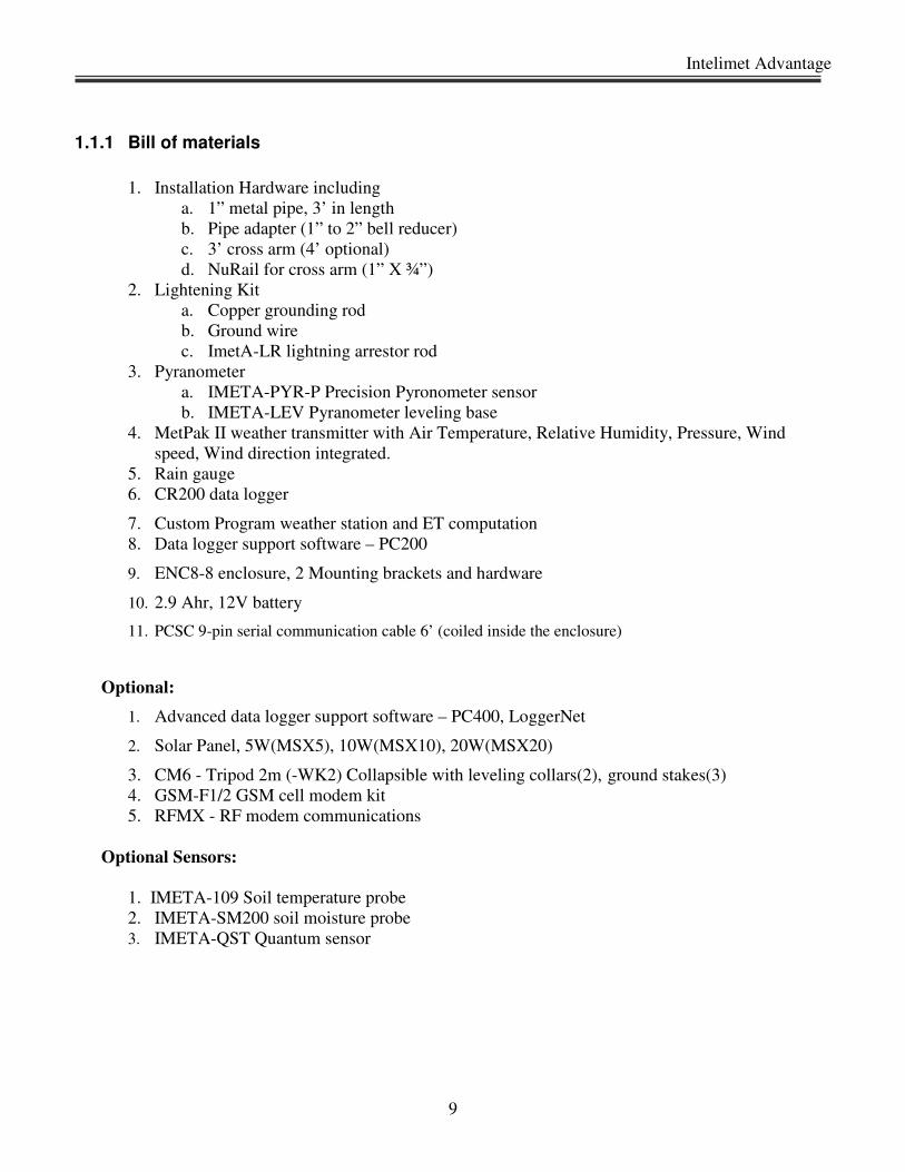
1.1.1 Bill of materials
1. Installation Hardware including
a. 1” metal pipe, 3’ in length
b. Pipe adapter (1” to 2” bell reducer)
c. 3’ cross arm (4’ optional)
d. NuRail for cross arm (1” X ¾”)
2. Lightening Kit
a. Copper grounding rod
b. Ground wire
c. ImetA-LR lightning arrestor rod
3. Pyranometer
a. IMETA-PYR-P Precision Pyronometer sensor
b. IMETA-LEV Pyranometer leveling base
4. MetPak II weather transmitter with Air Temperature, Relative Humidity, Pressure, Wind
speed, Wind direction integrated.
5. Rain gauge
6. CR200 data logger
7. Custom Program weather station and ET computation
8. Data logger support software – PC200
9. ENC8-8 enclosure, 2 Mounting brackets and hardware
10. 2.9 Ahr, 12V battery
11. PCSC 9-pin serial communication cable 6’ (coiled inside the enclosure)
Optional:
1. Advanced data logger support software – PC400, LoggerNet
2. Solar Panel, 5W(MSX5), 10W(MSX10), 20W(MSX20)
3. CM6 - Tripod 2m (-WK2) Collapsible with leveling collars(2), ground stakes(3)
4. GSM-F1/2 GSM cell modem kit
5. RFMX - RF modem communications
Optional Sensors:
1. IMETA-109 Soil temperature probe
2. IMETA-SM200 soil moisture probe
3. IMETA-QST Quantum sensor
Dynamax Inc
10
1.1.2 List of Tools required
Hardware supplied by the user
2” metal pipe, 4’ long (or) other compatible mounting pole/ tower
A general list of tools required
• Shovel – or post hole digger
• Large bucket or container to mix concrete
• 12” pipe wrench
• Teflon tape or pipe dope
• Small sledge hammer
• 12’ tape measure
• Felt-tipped marking pen
• Open-end wrenches: 3/8”, 7/16”, ½”, 9/16”
• Socket wrench and 7/16” deep well socket
• Level (12” – 24”)
• 5/64” Allen wrench
• Straight-bit screwdrivers (small, medium)
• Magnetic compass
• Volt/ Ohm meter
• Wire ties and tabs
• Conduit and associated tools as required for optional sensors
• 6’ ladder
• Lock and key for enclosure
Installation supplies needed:
• 2” metal pipe, 6’ long, threaded on one end for 2 in pipe thread.
• Concrete (quick set) mix to secure the vertical pipe, and fill a 4 ft hole (1-2 bags). 2-4 gals water
as recommended by concrete mix.
• Wooden stakes with tape, or bricks / rocks to hold the pipe vertically while setting.

Intelimet Advantage
11
1.2 Communication Options
Intelimet Advantage weather station based on CR200 logger offers a variety of communication
choices of user to connect between logger and PC using PC200 or PC400 or LoggerNet for advanced
network applications. Optional RS232, 150 to 250 ft RS232 extension cables can be added for direct
communication at 1200 baud. In addition, Intelimet Advantage supports remote communication options
given below with easy to use software features.
(Model COM210) Land-line Modem for remote field retrieval and control:
Customer provides telephone connections and PC MODEM (Hayes compatible) at computer location.
Many models are supported by the telecommunication software package included in PC400 or LoggerNet.
(Model: SHM) Short haul modem for communication using 4-wire cable:
For cable communication of up to 4Miles not possible using 9-wire serial cable. DIP switch selectable.
Easy to install and establish communication. Short-haul modems are line-powered, i.e. powered from
communicating device PC or data Logger. Refer to sections 8.2 for a detailed discussion on Modem setup
and hardware required.
CR206 or CR216 Spread spectrum radio data transmission
(with Model: RFMX base station )Radio Modem
Stand-alone radio modems provide efficient and low-cost serial communication to remote installations for
long distances of up to 40 Miles @ 9600 baud rate. The CR206 operates at 915 Mhz in the USA, and
CR216 operates ate 2.4 Ghz in most other countries.
RFMX modems allow point-to-point and point-to-multi-point configurations between central PC and
multiple data loggers connected to it. RFMX modems can be setup using PC400 or LoggerNet software.
RFMX is also offered in a modem kit (Model: RFMXMK) with surge protector, high-gain antenna and
connectors assembled in a weatherproof enclosure. Optional solar panels are available to power the
modem continuously. Contact Dynamax representative for selecting suitable products for your
application.
(Model: GSM) Dual-band GSM Cellular modem (900/1800, 850/1900):
GSM cellular modem for serial data rates of up to 115,200 bps uses cellular network where available.
GSM modem is very low power modem with 5 AHr battery capacity of 33Hours of communication and
20Days on idle. GSM modem installed in remote site can be connected to PC using a 56K landline
modem (Model: DNX9600) and telephone network. GSM-CMK is a cellular modem kit that includes
modem, surge protector, antenna and 15' long antenna cable assembled in a weatherproof enclosure,
optional solar panels for continuous powering the modem. Software setup for GSM modem is same as
that of Data Modem. Contact Dynamax representative for selecting suitable product for your application.

Dynamax Inc
12
2.0 SOFTWARE INSTALLATION
Intelimet Advantage is a completely integrated weather station capable of reading a variety of
meteorological sensors. Sensor readings are then stored in data logger’s memory. Data from the logger is
available for down load using support software. Downloaded data contains measurements from individual
sensors at the interval defined in the program and calculated ETP in mm/hour using Lascano-Van Bavel
Evapotranspiration (ETP) algorithm on an hourly basis. Intelimet Advantage weather station is based on
CR200 data logger. Hence, can be operated using any of the following data logger support software,
� PC200w – Included as standard with the weather station IMET-ADV, direct
connection with logger / PC only.
� PC400 – Option for dial-up, RF MODEMs, and point to multi-point loggers
� LoggerNet – Comprehensive networking options, with scheduling automatic data
retrieval and pakbus protocol networks. All communication links are supported: RF,
Tel MODEM, LANs, etc.
Each InteliMet Advantage weather station is supplied with PC200w software in a CD along with CR200
programs to read sensors and calculate ETP.
For the procedure to connect, program and download data, refer to chapter 5. In this manual we describe
working with Intelimet Advantage weather station using PC200w. Full capabilities of Intelimet
Advantage weather station is obtained by using two sets of software programs,
1. Data logger support software - PC200w
2. Data logger program IMET_MP2_Main.CR2 to load in to CR200 data logger for reading
variety of weather sensors, compute weather data and ETP from electrical measurements
and store to logger memory. A test program Imet_MP2_Tst.CR2 is also supplied for
setting up or troubleshooting.
3. In addition custom weather station configurations may require a modified version of
ImetCust1.cr2 program.
Intelimet Advantage
13
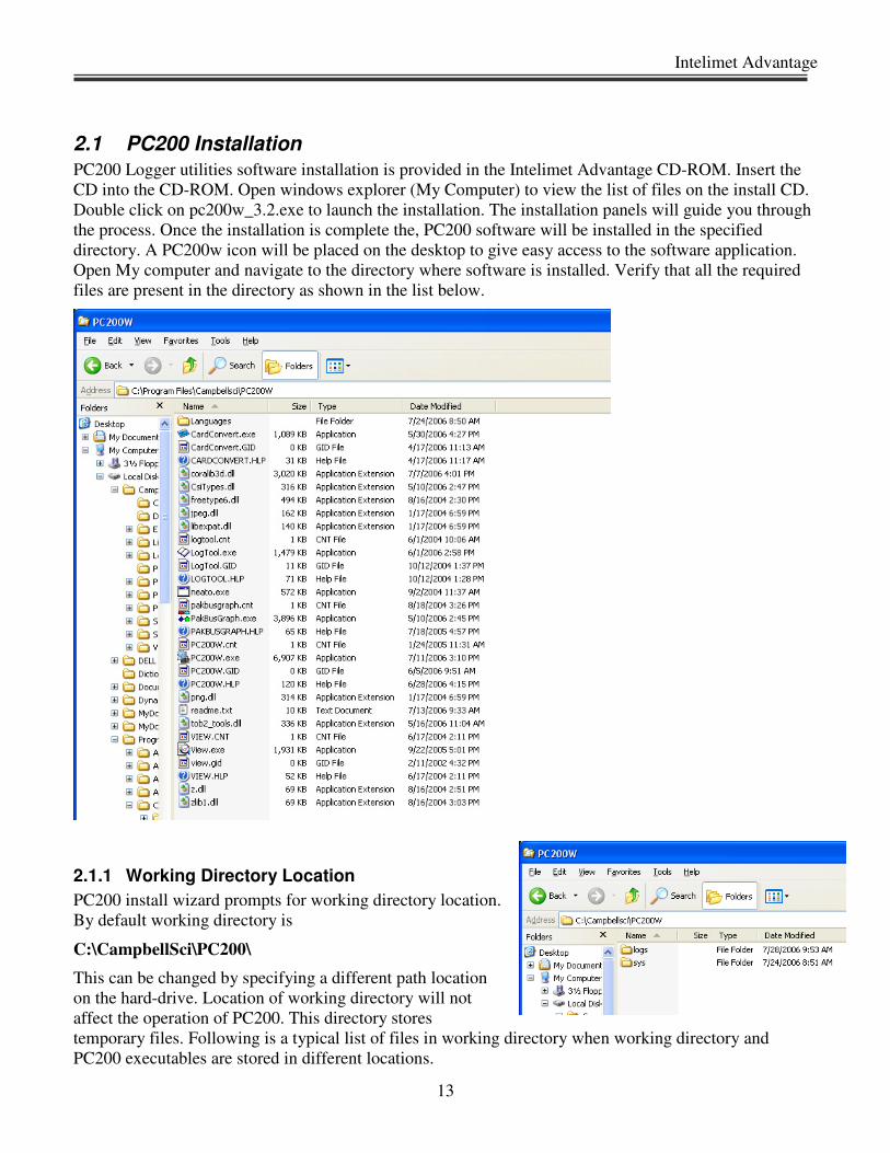
2.1 PC200 Installation
PC200 Logger utilities software installation is provided in the Intelimet Advantage CD-ROM. Insert the
CD into the CD-ROM. Open windows explorer (My Computer) to view the list of files on the install CD.
Double click on pc200w_3.2.exe to launch the installation. The installation panels will guide you through
the process. Once the installation is complete the, PC200 software will be installed in the specified
directory. A PC200w icon will be placed on the desktop to give easy access to the software application.
Open My computer and navigate to the directory where software is installed. Verify that all the required
files are present in the directory as shown in the list below.
2.1.1 Working Directory Location
PC200 install wizard prompts for working directory location.
By default working directory is
C:\CampbellSci\PC200\
This can be changed by specifying a different path location
on the hard-drive. Location of working directory will not
affect the operation of PC200. This directory stores
temporary files. Following is a typical list of files in working directory when working directory and
PC200 executables are stored in different locations.

Dynamax Inc
14
2.2 Lascano-VanBavel ET program for Intelimet Advantage (CR200)
Each Intelimet Advantage weather station is supplied with a standard CR200 program
IMET_MP2_Main.CR2 and a test program IMET_MP2_tst.CR2. These programs are supplied in
Intelimet Advantage software CD in the Programs directory. IMET_MP2_Main.CR2 program is loaded
into the logger before it is shipped out. Copy programs directory containing, IMET_MP2_Main.CR2 and
IMET_MP2_tst.CR2 programs to your PC on to the directory
C:\\Dynamax\Imet\.
These are READ ONLY files. Any changes to these files are not allowed; you can make changes in the
CRBasic editor or other text editor and save the modified program with a new file name.
In addition if the Intelimet Advantage system shipped is a custom set of sensors, with additional soil
moisture sensors etc., these are shipped with custom programs ImetCust1.CR2 and ImetCust1Tst.CR2 or
similar names in a standard CD. In this case, as before copy the contents of CD in addition to the standard
programs to,
C:\\Dynamax\Imet\

Intelimet Advantage
15
3.0 INTELIMET ADVANTAGE AND SENSOR INSTALLATION
Intelimet Advantage weather station is completely integrated system with data collection/
processing and storage unit along with basic meteorological sensors. IMET_MP2_Main.CR2
program supplied with the system can read all the basic weather sensors (solar radiation, air
temperature, RH, Wind speed, wind direction, rain gauge, optional soil temp. and soil moisture),
process data according to the applied algorithms and constants, compute ETP and store in data
loggers memory for retrieval at a later time. Intelimet Advantage weather station custom stations
will be assembled and programmed with a custom program before the units are shipped from our
factory. So, all the assembly and programming of the weather station is performed at our factory.
This leaves the end-user with only installation of the weather station at the required site.
This chapter discusses basics of installation on a steel pipe mast (standard), system mounting,
sensor wiring and solar panel installation. A separate manual is provided for optional tripod
installation. Selecting an appropriate site for installation of weather station is critical to obtain
accurate meteorological data. The site should be away from urban and natural obstructions such as
buildings and trees, or sprinkler irrigation. This chapter explains steps involved in
• Pole installation
• Intelimet Advantage weather station installation
• Solar panel installation
• Sensor installation
Refer to the following chapters for software setup, programming and data retrieval.
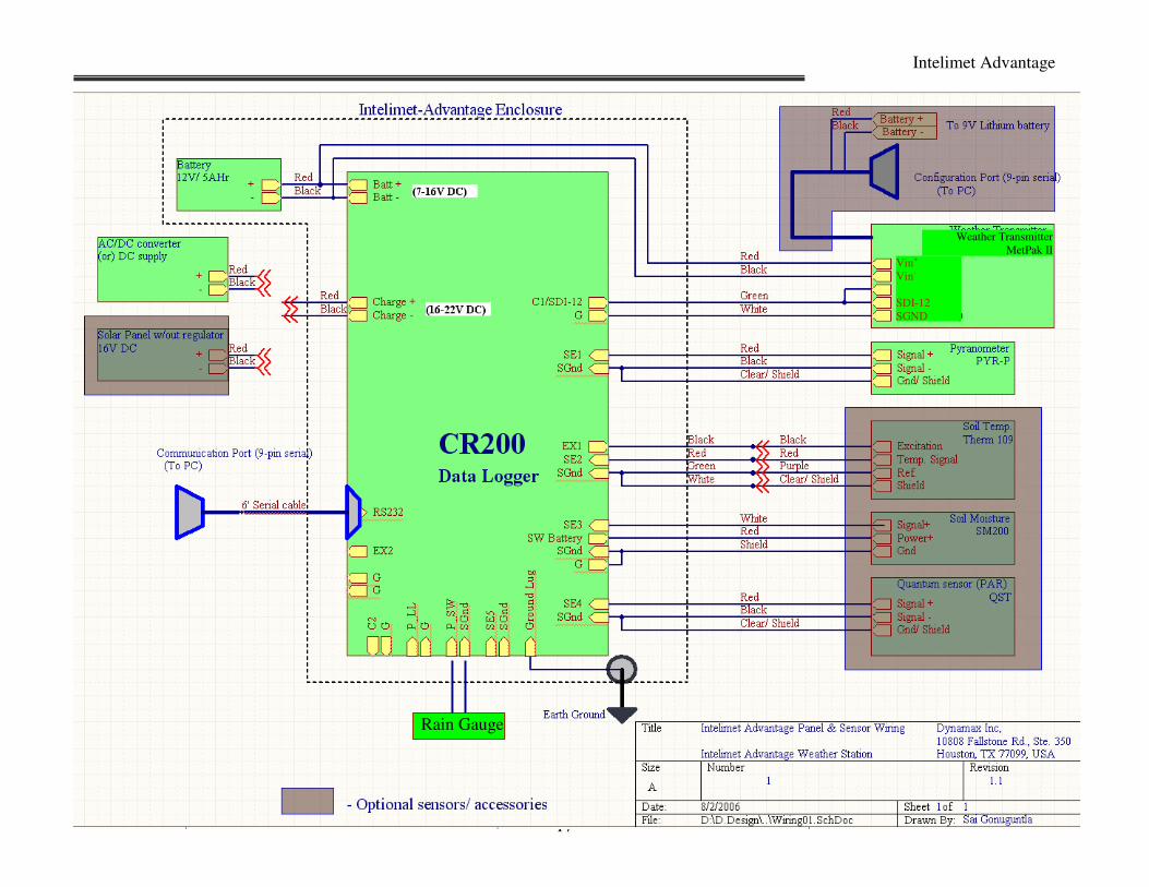
Intelimet advantage stations components and wiring is shown in the diagram below.

Dynamax Inc
16
Intelimet Advantage
17
Vin+
Vin-
SDI-12
SGND
Weather Transmitter
MetPak II
Rain Gauge

Dynamax Inc
18
Intelimet Advantage
19
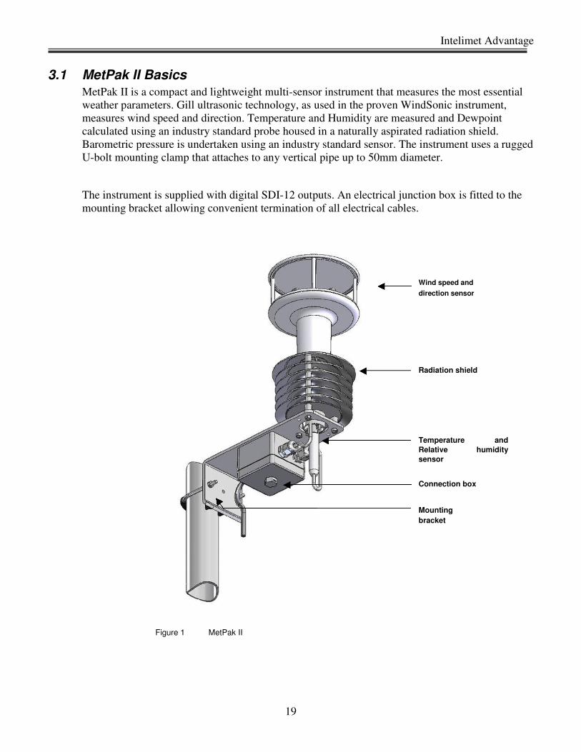
3.1 MetPak II Basics
MetPak II is a compact and lightweight multi-sensor instrument that measures the most essential
weather parameters. Gill ultrasonic technology, as used in the proven WindSonic instrument,
measures wind speed and direction. Temperature and Humidity are measured and Dewpoint
calculated using an industry standard probe housed in a naturally aspirated radiation shield.
Barometric pressure is undertaken using an industry standard sensor. The instrument uses a rugged
U-bolt mounting clamp that attaches to any vertical pipe up to 50mm diameter.
The instrument is supplied with digital SDI-12 outputs. An electrical junction box is fitted to the
mounting bracket allowing convenient termination of all electrical cables.
Wind speed and
direction sensor
Radiation shield
Temperature and
Relative humidity
sensor
Connection box
Mounting bracket
Figure 1 MetPak II

Dynamax Inc
20
3.2 Intelimet Advantage and Tripod Installation
Operation, Overview and Quick start guide
1. Site selection and preparation.
2. Unpacking system
3. Mount user supplied pipe in the ground and add 1”
pipe on top to give a total height of 6ft.
4. Install MetPak II on center pipe, orient to the North.
5. Mount Intelimet Advantage enclosure, connect
sensor cables, connect Power, and
Connect Grounding.
6. Install optional: solar panel, lightning rod, antenna
(if applicable).
7. Connect personal computer
8. Install datalogger support software (PC200w) on PC
9. Connect power to the weather station. Intelimet Advantage starts collecting data every minute and
calculates ET and saves to logger memory every hour using the default program stored in the
loggers non-volatile memory.
10. Using data logger support software, connect to the Intelimet Advantage weather station. Set the
logger internal clock with the PC time/date Click on the Set Data logger Clk
11. Download IMET_MP2_tst.CR2 to logger Intelimet Advantage weather station starts measuring
sensors every 10s and store the collected data and calculations to memory every minute. Monitor
sensor output and calculated ET data. If the sensors data and ETP output are with in the acceptable
ranges, means that the sensors and system are installed properly.
12. Now send the original logging program IMET_MP2_Main.CR2 program, for site-specific
parameters, save with a different name. Compile the new program and send to logger. Now the
data logger collects sensor data every minute, compute ET every hour and store hourly and daily
data to the logger.
13. After few days down load data stored in the logger memory.
PC200 -> Connect -> Collect all button
Retrieve data into *.csv files.
14. The retrieved data contains average weather sensor measurements at 1 hour intervals and
calculated ETP at 1 hour interval.
Intelimet Advantage
21
3.2.1 Single Pole Installation:
The sensor default height is 6 ft or 2m above the ground surface. If you wish to add height to 3m
or more, an optional tripod or mast mounting system is required for stability in the field.
The following parts are supplied as part of the field installation kit.
• 1” steel pipe, 4’ long
• ¾” steel pipe, 3’ long cross arm
• Nu-rails (qty-1)
• Lightning Rod with Clamp (optional)
• Grounding Rod with Clamp
• 10’, 12AWG wire ground wire
• Cable ties
In addition the user must supply the following materials:
• 2” metal pipe, 6’ long, threaded on one end for 2 in pipe thread.
• Concrete (quick set) mix to secure the vertical pipe, and fill a 4 ft hole (1-2 bags). 2-4 gals
water as recommended by concrete mix.
• Wooden stakes, and tape to position and hold pipe while setting concrete.
• Tools listed in the previous sections
• Refer to the Field setup drawing in the next page.
• Select site for installing tripod and weather station. The site should be away from obstructions and
sprinklers. A flat ground is recommended for installation, even though the unit can be installed in
many different terrains with some professional help.
• Prepare an area of 10’ diameter for installing tripod with little disturbance to the ground surface or
vegetation.
• Dig a posthole of 6- 8 in diameter and four ft deep with a shovel or with a posthole digger. Mix
two bags of quick set concrete mix and pour into the hole. Insert the 2” pipe in the pit and fix the
pole position vertically with wooden stakes and tape.
• The 2” pipe should extend only two feet above the ground surface.
• You may also tap the pole into the bottom of the hole with a hammer as long as the threads are
protected. Then pile rocks or bricks around the pole to hold the position vertical. Check the
vertical pole with a level to make sure it is vertical before leaving for the day. Wait for about 24
hours while the concrete sets.
• Apply pipe dope or Teflon tape to threads on the threaded pipes. To prevent cross threading, hand
thread the bell reducer and then tighten with a pipe wrench. Then hand thread the 4 ft X1” pipe
mast into the threaded reducer and then tighten with a pipe wrench.
Dynamax Inc
22
• Install Nu-rail (3/4 X 1” ) on the end of 4’X1” diameter pipe, both supplied with the weather
station. Adjust the Nu Rail to 1 ft 5 in below the top of the mast, so the cross arm will point
roughly east and west. Tighten the setscrews.
• Insert cross arm in the horizontal bore of Nu-rail (3/4’). Center the cross arm, and tighten using
set screws.
• Install the second Nu-rail (3/4 X ¾) with the short ¾ “ vertical mounting pipe on one end of the
cross arm.
• Now install weather transmitter on the new rail on one end of the cross arm as shown in the setup
drawing. (for details refer to the section 3.4)
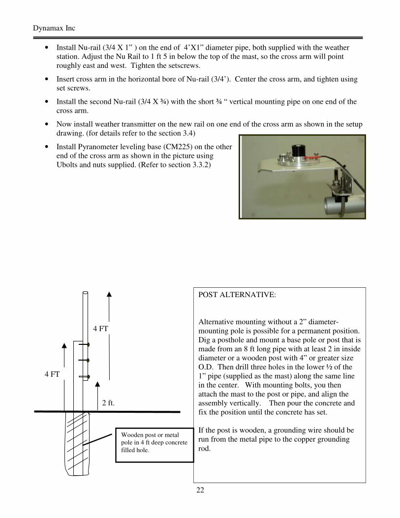
• Install Pyranometer leveling base (CM225) on the other
end of the cross arm as shown in the picture using
Ubolts and nuts supplied. (Refer to section 3.3.2)
POST ALTERNATIVE:
Alternative mounting without a 2” diameter-
mounting pole is possible for a permanent position.
Dig a posthole and mount a base pole or post that is
made from an 8 ft long pipe with at least 2 in inside
diameter or a wooden post with 4” or greater size
O.D. Then drill three holes in the lower ½ of the
1” pipe (supplied as the mast) along the same line
in the center. With mounting bolts, you then
attach the mast to the post or pipe, and align the
assembly vertically. Then pour the concrete and
fix the position until the concrete has set.
If the post is wooden, a grounding wire should be
run from the metal pipe to the copper grounding
rod.
4 FT
4 FT
Wooden post or metal
pole in 4 ft deep concrete
filled hole.
2 ft.
Intelimet Advantage
23
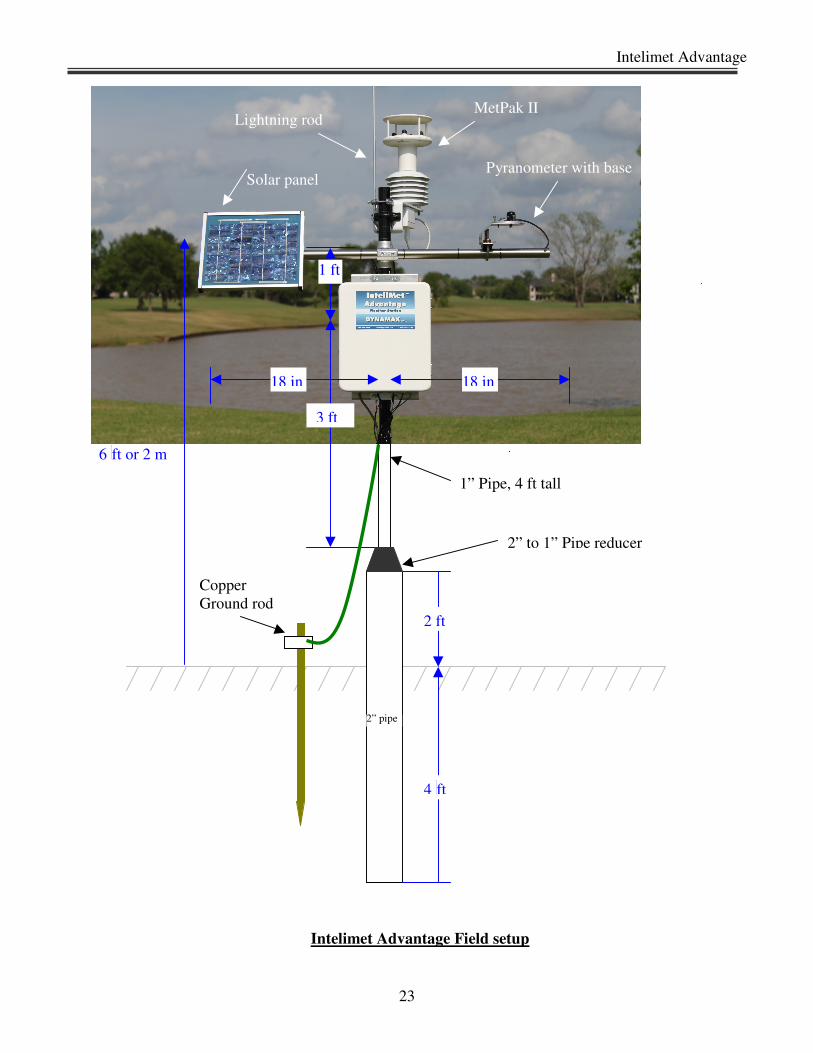
Intelimet Advantage Field setup
2 ft
4
ft
2” pipe
18 in
3 ft
1 ft
18 in
2” to 1” Pipe reducer
1” Pipe, 4 ft tall
Pyranometer with base
Copper
Ground rod
Lightning rod MetPak II
Solar panel
6
ft or 2 m
Dynamax Inc
24
• Install pyranometer sensor on the leveling plate and secure with bottom screw.
• Install pyranometer leveling plate on top of the mounting bracket, leave the inner screws loose for
now.
• Install leveling assembly and bracket onto the cross arm opposite the MetPak II transmitter. The
u-bolts can be tightened after you level the plate roughly. Now adjust the Allen (hex) set screws
to level the bubble in the leveling plate, then tighten the inner fixing screws with a screwdriver.
• Install lightning rod ( if applicable) on the pole mast.
• Rotate the threads and make sure the reducer coupling is holding both 2” and 1” pipes firmly.
• Lightning Rod: Position the lightning rod 4” down from the top of the mast, attach lightning rod
to the mast and make sure the lightning rod set screw is tight.
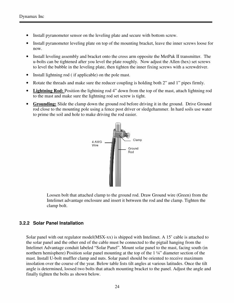
• Grounding: Slide the clamp down the ground rod before driving it in the ground. Drive Ground
rod close to the mounting pole using a fence post driver or sledgehammer. In hard soils use water
to prime the soil and hole to make driving the rod easier.
Loosen bolt that attached clamp to the ground rod. Draw Ground wire (Green) from the
Intelimet advantage enclosure and insert it between the rod and the clamp. Tighten the
clamp bolt.
3.2.2 Solar Panel Installation
Solar panel with out regulator model(MSX-xx) is shipped with Intelimet. A 15’ cable is attached to
the solar panel and the other end of the cable must be connected to the pigtail hanging from the
Intelimet Advantage conduit labeled “Solar Panel”. Mount solar panel to the mast, facing south (in
northern hemisphere) Position solar panel mounting at the top of the 1 ¼” diameter section of the
mast. Install U-bolt muffler clamp and nuts. Solar panel should be oriented to receive maximum
insolation over the course of the year. Below table lists tilt angles at various latitudes. Once the tilt
angle is determined, loosed two bolts that attach mounting bracket to the panel. Adjust the angle and
finally tighten the bolts as shown below.

Intelimet Advantage
25
(For MSX10, MSX20 Setup) (For MSX5 Setup)
3.2.3 Install Intelimet Advantage Enclosure
Intelimet Advantage weather station enclosure contains CR200 data logger, and other storage or
communication peripherals if any. RF or GSM modem if purchased is assembled inside the enclosure
with surge protector. Sensor cables, Power cables, Communication cables connected to the data logger
or any peripherals routed out of the enclosure through cable glands each marked outside the enclosure
or on the cable itself. So it is not necessary for an end-user to make any wiring inside the enclosure.
All the connectors are accessible out of the box. Position enclosure on the north side of the mast or
tower (northern hemisphere). Secure enclosure as shown in the figure using U-bolts and mounting
brackets. Route the 12AWG wire from the Ground Lug on the enclosure to the tripod-grounding
clamp. Tighten the screws. Grounding is critical not only for the accuracy of data/ reduce signal noise
but also to protect equipment from any lightening surges.
Dynamax Inc
26
3.3 Sensor Installation
Intelimet Advantage weather station sensors basic or additional are supplied with sensors
connected to the data logger in the Intelimet Advantage enclosure. In this section we discuss the
procedure to install the sensors on tripod along with Intelimet Advantage enclosure, cable routing, setting
up/ orientation of the sensors and entering parameters in the Intelimet Advantage/ CR200 program.
3.3.1 MetPak II Installation
MetPak II is an integrated portable weather station with no moving parts. Hence, it is installation,
maintenance and operation is much simpler compared to traditional weather station with moving parts.
Even with all the simplicities provided by the new weather station, site selection and positioning of the
sensor and weather station is critical to the accuracy of measurements. The site should represent the
general area of interest. Weather station should be installed away from obstructions such as buildings,
trees to avoid turbulence caused by the obstructions.
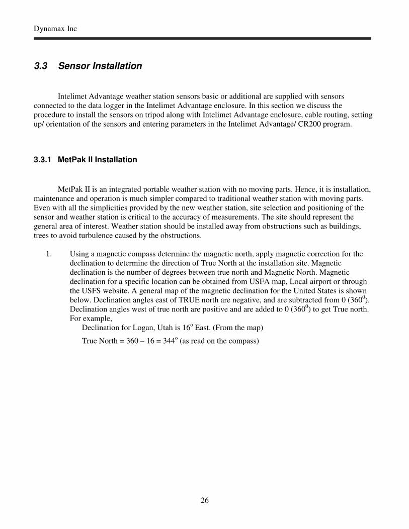
1. Using a magnetic compass determine the magnetic north, apply magnetic correction for the
declination to determine the direction of True North at the installation site. Magnetic
declination is the number of degrees between true north and Magnetic North. Magnetic
declination for a specific location can be obtained from USFA map, Local airport or through
the USFS website. A general map of the magnetic declination for the United States is shown
below. Declination angles east of TRUE north are negative, and are subtracted from 0 (3600).
Declination angles west of true north are positive and are added to 0 (3600) to get True north.
For example,
Declination for Logan, Utah is 16o East. (From the map)
True North = 360 – 16 = 344o (as read on the compass)
Intelimet Advantage
27
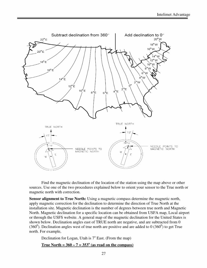
Find the magnetic declination of the location of the station using the map above or other
sources. Use one of the two procedures explained below to orient your sensor to the True north or
magnetic north with correction.
Sensor alignment to True North: Using a magnetic compass determine the magnetic north,
apply magnetic correction for the declination to determine the direction of True North at the
installation site. Magnetic declination is the number of degrees between true north and Magnetic
North. Magnetic declination for a specific location can be obtained from USFA map, Local airport
or through the USFS website. A general map of the magnetic declination for the United States is
shown below. Declination angles east of TRUE north are negative, and are subtracted from 0
(3600). Declination angles west of true north are positive and are added to 0 (360
0) to get True
north. For example,
Declination for Logan, Utah is 7o East. (From the map)
True North = 360 – 7 = 353o (as read on the compass)

Dynamax Inc
28
Loosen the fixing screw on the attachment so that you can rotate the device. Use a compass
to determine that the transducer heads of MetPak II are exactly in line with the True North and that
the triangle on the bottom of the MetPak II points True North. Tighten the fixing screw when the
bottom arrow is exactly aligned to north. In this case MetPak II sensor is aligned to the True North
and hence no direction correction is required. If the sensor could not be aligned to True North, a
direction correction can be entered in the sensor settings such that the sensor output is corrected
for this deviation. Refer to Appendix C for Magnetic direction correction.
Intelimet Advantage
29
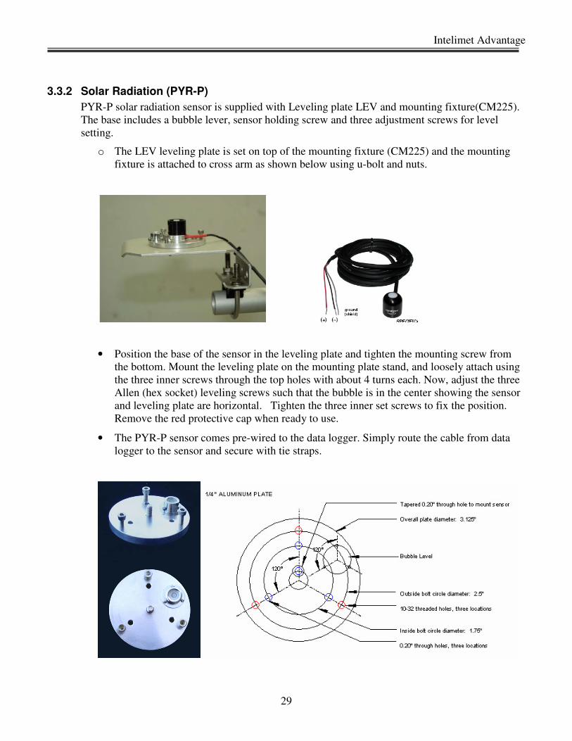
3.3.2 Solar Radiation (PYR-P)
PYR-P solar radiation sensor is supplied with Leveling plate LEV and mounting fixture(CM225).
The base includes a bubble lever, sensor holding screw and three adjustment screws for level
setting.
o The LEV leveling plate is set on top of the mounting fixture (CM225) and the mounting
fixture is attached to cross arm as shown below using u-bolt and nuts.
• Position the base of the sensor in the leveling plate and tighten the mounting screw from
the bottom. Mount the leveling plate on the mounting plate stand, and loosely attach using
the three inner screws through the top holes with about 4 turns each. Now, adjust the three
Allen (hex socket) leveling screws such that the bubble is in the center showing the sensor
and leveling plate are horizontal. Tighten the three inner set screws to fix the position.
Remove the red protective cap when ready to use.
• The PYR-P sensor comes pre-wired to the data logger. Simply route the cable from data
logger to the sensor and secure with tie straps.
Dynamax Inc
30
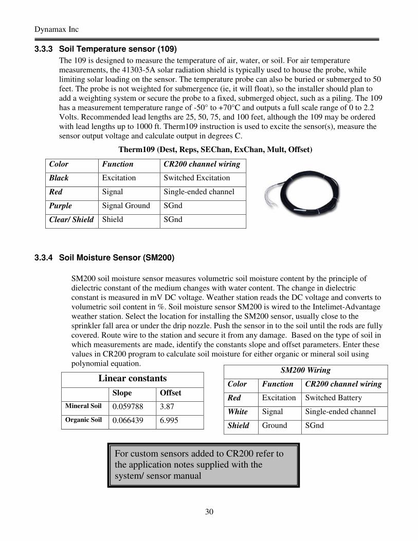
3.3.3 Soil Temperature sensor (109)
The 109 is designed to measure the temperature of air, water, or soil. For air temperature
measurements, the 41303-5A solar radiation shield is typically used to house the probe, while
limiting solar loading on the sensor. The temperature probe can also be buried or submerged to 50
feet. The probe is not weighted for submergence (ie, it will float), so the installer should plan to
add a weighting system or secure the probe to a fixed, submerged object, such as a piling. The 109
has a measurement temperature range of -50° to +70°C and outputs a full scale range of 0 to 2.2
Volts. Recommended lead lengths are 25, 50, 75, and 100 feet, although the 109 may be ordered
with lead lengths up to 1000 ft. Therm109 instruction is used to excite the sensor(s), measure the
sensor output voltage and calculate output in degrees C.
Therm109 (Dest, Reps, SEChan, ExChan, Mult, Offset)
3.3.4 Soil Moisture Sensor (SM200)
SM200 soil moisture sensor measures volumetric soil moisture content by the principle of
dielectric constant of the medium changes with water content. The change in dielectric
constant is measured in mV DC voltage. Weather station reads the DC voltage and converts to
volumetric soil content in %. Soil moisture sensor SM200 is wired to the Intelimet-Advantage
weather station. Select the location for installing the SM200 sensor, usually close to the
sprinkler fall area or under the drip nozzle. Push the sensor in to the soil until the rods are fully
covered. Route wire to the station and secure it from any damage. Based on the type of soil in
which measurements are made, identify the constants slope and offset parameters. Enter these
values in CR200 program to calculate soil moisture for either organic or mineral soil using
polynomial equation.
Linear constants
Slope Offset
Mineral Soil 0.059788 3.87
Organic Soil 0.066439 6.995
Color Function CR200 channel wiring
Black Excitation Switched Excitation
Red Signal Single-ended channel
Purple Signal Ground SGnd
Clear/ Shield Shield SGnd
SM200 Wiring
Color Function CR200 channel wiring
Red Excitation Switched Battery
White Signal Single-ended channel
Shield Ground SGnd
For custom sensors added to CR200 refer to
the application notes supplied with the
system/ sensor manual
Intelimet Advantage
31
4.0 Lascano-VanBavel ETP Program
The value of ETP (Potential Evapotranspiration) is a reference measure of the evaporative demand, as
determined by weather conditions. Using Lascano-VanBavel ET algorithm we calculate ETP estimation
from a well-watered short grass. ETP is normally expressed in mm/hr or inch/hr and daily-accumulated
values are expressed in mm/day or inches/day. It can be related to hourly or daily data for the sap flow
rate, and used to normalize such data against day-to-day variations in the weather, or to identify
deviations in the sap flow rate from normal patterns. ETP is also used to create and index reference to
schedule irrigation and to calculate crop coefficients. Lascano-VanBavel ET algorithm is embedded in
Dynamax weather stations to calculate and output ETP. In addition custom weather station programs can
also be supplied with embedded ET calculations. The new Lascano-VanBavel RCM algorithm for ETP
does not assume a value for temperature and saturation humidity at the evaporation surface, but rather
derives both from closing the energy balance.
In Intelimet Advantage weather station, weather measurements and ET computation are integrated
hence, there is no further processing of the collected data. Output of data loggers already contains average
weather measurements, computed ET, ready for observation and analysis.
4.1 Application of ETP Information – with Sap Flow
In the interpretation of data on the sap flow rates in crops and trees it is essential to compare their hourly
pattern within that of the concurrent evaporation demand. A general comparison can also be made of
daily totals, as an indication of water stress, or other influences that cause the plant to use less water than
expected.
For example, the weather data may give a value of 10.3 mm/day for ETp and, from stem flow gauges, the
total water used by a tree on 10 m2 of land is found as 94 kg/day (converts to 9.4 mm/day). This converts
to a Kc of 0.91. On the next day, if the value for ETp is 10.6 mm/day, but the water use measured as 46
kg/day (4.6 mm), stomatal closure and reduced transpiration has occurred. The reduced transpiration can
be a result of reduced soil water availability, but possibly a result of other factors such as low root zone
temperature, vascular disease, or others.
In the case of irrigation management, a comparison of the ETp rates with the stem flow data serves the
dual purpose of diagnosing the need for supplying water and the basis for calculating how much water
should be applied. For example, if a four-day sequence of water use a transpiration showed, respectively,
94 kg/day (well watered), 96 kg/day, 50 kg/day (stressed), and 28 kg/day (stressed), while the ETp was
essentially constant, we would know that irrigation is needed and overdue, on the 4th
day. In this case the
plant water stress caused a decrease in ETa by about 70%.
By adding up the sap flow, we also know that the total amount that has to be replaced equals 266 kg. To
this amount we must add the losses by soil evaporation, which must be estimated from previous data.
Assuming one tree occupies a 10 m2 area, and if the transpiration is 80% of ETp, then the suggested
irrigation is 333 kg or 86 gallons (per 10 m2), ie 266 kg / 80%. That would translate to an irrigation of
Dynamax Inc
32
33.3 mm to replenish the water used over four days. Many variations on this theme can be formulated for
a specific application.
One caution should be stated. The ETp estimate is only a quantitative measure of the evaporative demand
of a well watered turf grass ¾ “ high, and is not intended to be an estimate of the actual water use by the
crop or the trees, even if they are well watered. Therefore, the two variables, ETp and stem or trunk flow
rate, are expressed as mm per hour and kg/plant/hour, respectively, even though the water use by
vegetation is often also expressed as mm per hour or per day. The relation between daily ETp and daily
transpiration is not even necessarily linear, as most Kc constants will assume. ETa – Actual
Evapotranspiration may not be constant over the entire range of weather conditions or the development
period of a crop.
4.2 ET Program Basics
This section covers the basics of Evapotranspiration algorithms and the ET algorithm implemented in
IMET_MP2_Main.CR2. ET program contains two constants that are always set for the installation site,
and two constants that could be modified for various situations. Only persons thoroughly familiar with
ETP modeling should modify parameters lev and zot. Normally, the last two constants are altered to
account for the barometric pressure and the height of the wind measurement. The present form of the
program is adapted to metric units. Each user needs to know the height of the weather station above
ground level.
zom = 2.0 wind speed height of measurement in meters, 2 m typical.
Only an advanced user with expertise and knowledge in the various ET models and roughness parameters
for various crops must attempt to change the following parameters.
zot = 0.0005 surface roughness parameter in m, for ¾ in. high turf grass
lev = 2.44 x 10⁶ latent heat of vaporization – J/kg
has = 1004.0 Specific air heat capacity in J/KgC at 300
C
In this section we discuss definition of these parameters and their units followed by procedure to modify
these parameters in CR200 program to meet the geography of the location of weather station.
Intelimet Advantage
33
4.3 ET Variables and complete algorithm
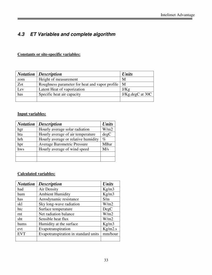
Constants or site-specific variables:
Notation Description Units zom Height of measurement M
Zot Roughness parameter for heat and vapor profile M
Lev Latent Heat of vaporization J/Kg
has Specific heat air capacity J/Kg.degC at 30C
Input variables:
Notation Description Units hgr Hourly average solar radiation W/m2
hta Hourly average of air temperature degC
hrh Hourly average or relative humidity %
hpr Average Barometric Pressure MBar
hws Hourly average of wind speed M/s
Calculated variables:
Notation Description Units had Air Density Kg/m3
hum Ambient Humidity Kg/m3
has Aerodynamic resistance S/m
skl Sky long-wave radiation W/m2
htc Surface temperature DegC
rnt Net radiation balance W/m2
sht Sensible heat flux W/m2
hums Humidity at the surface Kg/m3
evt Evapotranspiration Kg/m2.s
EVT Evapotranspiration in standard units mm/hour

Dynamax Inc
34
RCM ET Algorithm:
( )( )5.0817.3
6
2.1013
)(10002361.0501.2
:
−⋅−⋅=
⋅⋅−=
Eelfeabp
onlyreferenceforheregivenhtalev
VariablesSpecificSite
Note: abp is measured by the Intelimet Advantage, so no calculation is needed.
( )
( )
−
⋅
=
⋅=
⋅=
+
⋅
1078.6ln2693882.17
1078.6ln3.237
1078.6
:int
3.237
2693882.17
a
a
asa
T
T
as
e
e
hdp
hrhTee
eTe
nCalculatioPoDew
a
a
( )
+
+⋅
⋅⋅+⋅+⋅−=
<+⋅
=⋅
=
+⋅=
⋅=
2.273
1500
4
22
237269.17
08241.070.0()2.273(867.5
1.01.016.0
ln
16.0
ln
2.273323.1
2.10131548.1
:lg
hta
hdp
hdp
ehumhtaEskl
hwswhenhws
zot
zom
rasorhws
zot
zom
ras
hdp
ehum
abphad
ncalculatioETfororithmaRCM
( ) ( )
( )
+
⋅⋅⋅
⋅
−+
⋅
−⋅+
⋅⋅⋅−+++⋅−−⋅=
+⋅
=
htc
hta
hashad
raslev
ras
humhtc
e
rashta
hashadhtchtasklhtcEhgrroothtc
htc
htchtc
,
2.273
16.303
2.273323.1
2.273
16.303)2.273(867.580.0
237269.17
4
10
( )( )( )
( )
3600
2.273
16.303
2.273867.580.04
⋅=
+=
⋅+
−⋅⋅⋅=
++⋅−−⋅=
evtEVT
lev
shtrntevt
rashta
htchtahashadsht
sklhtcEhgrrnt
Intelimet Advantage
35
4.4 CR200 Program for Intelimet Advantage and ET computation
Every standard and custom Intelimet Advantage weather station is tested at our factory and
supplied with a program to read sensors every minute, calculate average, compute ET and store to logger
every hour. This enables the user to simply power up the weather station and the unit starts collecting data
as long as all the sensors are connected and operating properly. In addition to this each system is supplied
with software CD containing CR200 program loaded into the logger and a test program. For example a
test program can read sensors every 5 seconds and calculate and store to logger memory every minute.
This test program is helpful as a learning tool for a new user as well as for testing the installation for any
problems. This is also a helpful tool in trouble shooting the weather station, sensors, cabling or
installation.
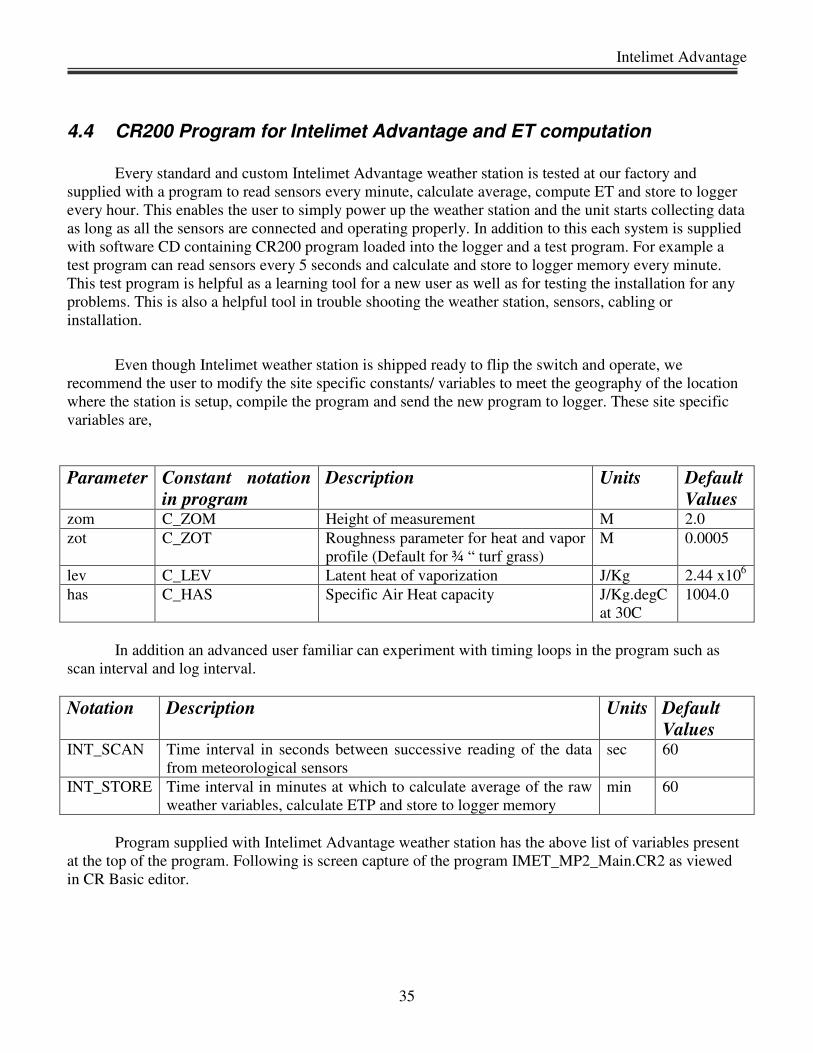
Even though Intelimet weather station is shipped ready to flip the switch and operate, we
recommend the user to modify the site specific constants/ variables to meet the geography of the location
where the station is setup, compile the program and send the new program to logger. These site specific
variables are,
Parameter Constant notation
in program
Description Units Default
Values zom C_ZOM Height of measurement M 2.0
zot C_ZOT Roughness parameter for heat and vapor
profile (Default for ¾ “ turf grass)
M 0.0005
lev C_LEV Latent heat of vaporization J/Kg 2.44 x10⁶
has C_HAS Specific Air Heat capacity J/Kg.degC
at 30C
1004.0
In addition an advanced user familiar can experiment with timing loops in the program such as
scan interval and log interval.
Notation Description Units Default
Values INT_SCAN Time interval in seconds between successive reading of the data
from meteorological sensors
sec 60
INT_STORE Time interval in minutes at which to calculate average of the raw
weather variables, calculate ETP and store to logger memory
min 60
Program supplied with Intelimet Advantage weather station has the above list of variables present
at the top of the program. Following is screen capture of the program IMET_MP2_Main.CR2 as viewed
in CR Basic editor.

Dynamax Inc
36
Notice in the figure timing loop parameters and site-specific parameters appear at the top of the program
to enable any users identify these variables and make changes if necessary.
Const INT_SCAN
Const INT_STORE
Const C_ZOM
Const C_ZOT
Const C_LEV
Const C_HAS
The following site-specific parameters must be modified to meet the geographical location at which the
station is setup to collect data. Timing loop parameters are options as the industry standard is to collect
data every hour.
Const C_ZOM
Const C_ZOT
Const C_LEV
Const C_HAS
Intelimet Advantage
37
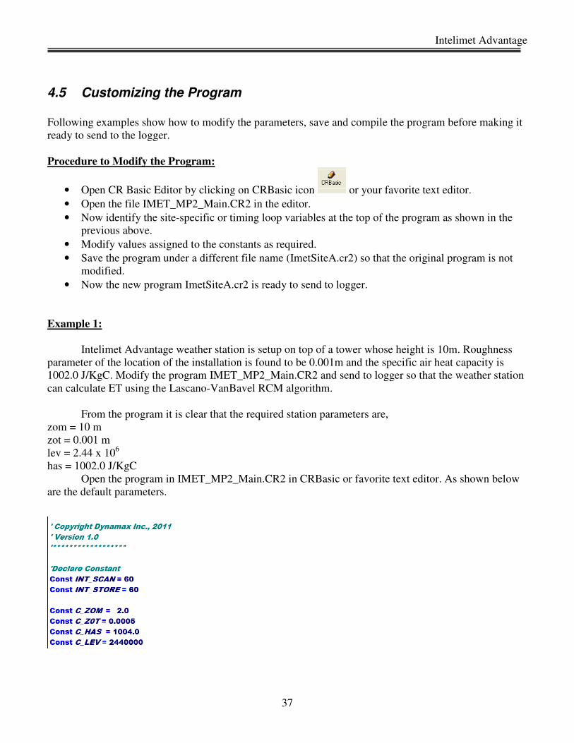
4.5 Customizing the Program
Following examples show how to modify the parameters, save and compile the program before making it
ready to send to the logger.
Procedure to Modify the Program:
• Open CR Basic Editor by clicking on CRBasic icon or your favorite text editor.
• Open the file IMET_MP2_Main.CR2 in the editor.
• Now identify the site-specific or timing loop variables at the top of the program as shown in the
previous above.
• Modify values assigned to the constants as required.
• Save the program under a different file name (ImetSiteA.cr2) so that the original program is not
modified.
• Now the new program ImetSiteA.cr2 is ready to send to logger.
Example 1:
Intelimet Advantage weather station is setup on top of a tower whose height is 10m. Roughness
parameter of the location of the installation is found to be 0.001m and the specific air heat capacity is
1002.0 J/KgC. Modify the program IMET_MP2_Main.CR2 and send to logger so that the weather station
can calculate ET using the Lascano-VanBavel RCM algorithm.
From the program it is clear that the required station parameters are,
zom = 10 m
zot = 0.001 m
lev = 2.44 x 10⁶
has = 1002.0 J/KgC
Open the program in IMET_MP2_Main.CR2 in CRBasic or favorite text editor. As shown below
are the default parameters.

Dynamax Inc
38
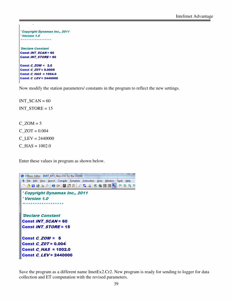
Now modify the station parameters/ constants in the program to reflect the new settings.
C_ZOM = 10
C_ZOT = 0.0005
C_LEV = 2440000
C_HAS = 1004.0
Enter these values in program as shown below.
Save the program as a different name ImetEx1.Cr2. The program is ready for sending to logger for data
collection and ET computation with the revised parameters.
Example 2:
Intelimet Advantage weather station is setup on top of a tower whose height is 5m. Roughness
parameter of the location of the installation is found to be 0.004m and the specific air heat capacity is
1002.0 J/KgC. The station is located in a research site and the project requires sensor data to be read every
60 seconds and store to logger every 15 minutes. Modify the program IMET_MP2_Main.CR2 and send to
logger so that the Intelimet Advantage weather station can calculate ET using the Lascano-VanBavel
RCM algorithm.
From the program it is clear that the required station parameters are,
zom = 5 m
zot = 0.004 m
lev = 2.44 x 10⁶.
has = 1002.0 J/KgC
Scan interval = 60 sec
Store interval = 15 min
Open the program in IMET_MP2_Main.CR2 in CRBasic or favorite text editor. As shown below are the
default parameters.
Intelimet Advantage
39
Now modify the station parameters/ constants in the program to reflect the new settings.
INT_SCAN = 60
INT_STORE = 15
C_ZOM = 5
C_ZOT = 0.004
C_LEV = 2440000
C_HAS = 1002.0
Enter these values in program as shown below.
Save the program as a different name ImetEx2.Cr2. New program is ready for sending to logger for data
collection and ET computation with the revised parameters.
Dynamax Inc
40
4.6 Sensor Constants
A basic Intelimet Advantage weather station is supplied with the following sensors,
MetPak II Integrated weather transmitter
PYR-P Pyranometer
MetPak II is factory configured for use with Intelimet Advantage weather station. Similarly PYR-
P pyranometer sensor is factory configured to read global solar radiation in W/m2. All PYR-P
sensors are factory calibrated for a multiplier of 5.00. Hence it is not necessary to make any
changes to the pyranometer settings.
In addition to the basic sensors, Intelimet Advantage weather station can be added with optional
sensors such as
Soil Moisture sensor (SM200)
Soil temperature sensor (109)
Quantum Sensors (QSO)
In the case of optional sensors it may be necessary to enter constants for those sensors. Please refer
to the documentation supplied with the custom sensors for constants and programming. An
example of how to change the constants for soil moisture sensor (SM200) is explained below.
Soil moisture sensor SM200 measures % soil moisture by volume in the sample. The sensor
measures voltage output that is proportional to the dielectric constant of the soil. This voltage
output can then be converted to %SM using a multiplier and an offset representing the type of soil.
The following table lists the multiplier and offset for mineral or organic soil.
Linear constants
Slope Offset
Mineral Soil 0.059788 3.87
Organic Soil 0.066439 6.995
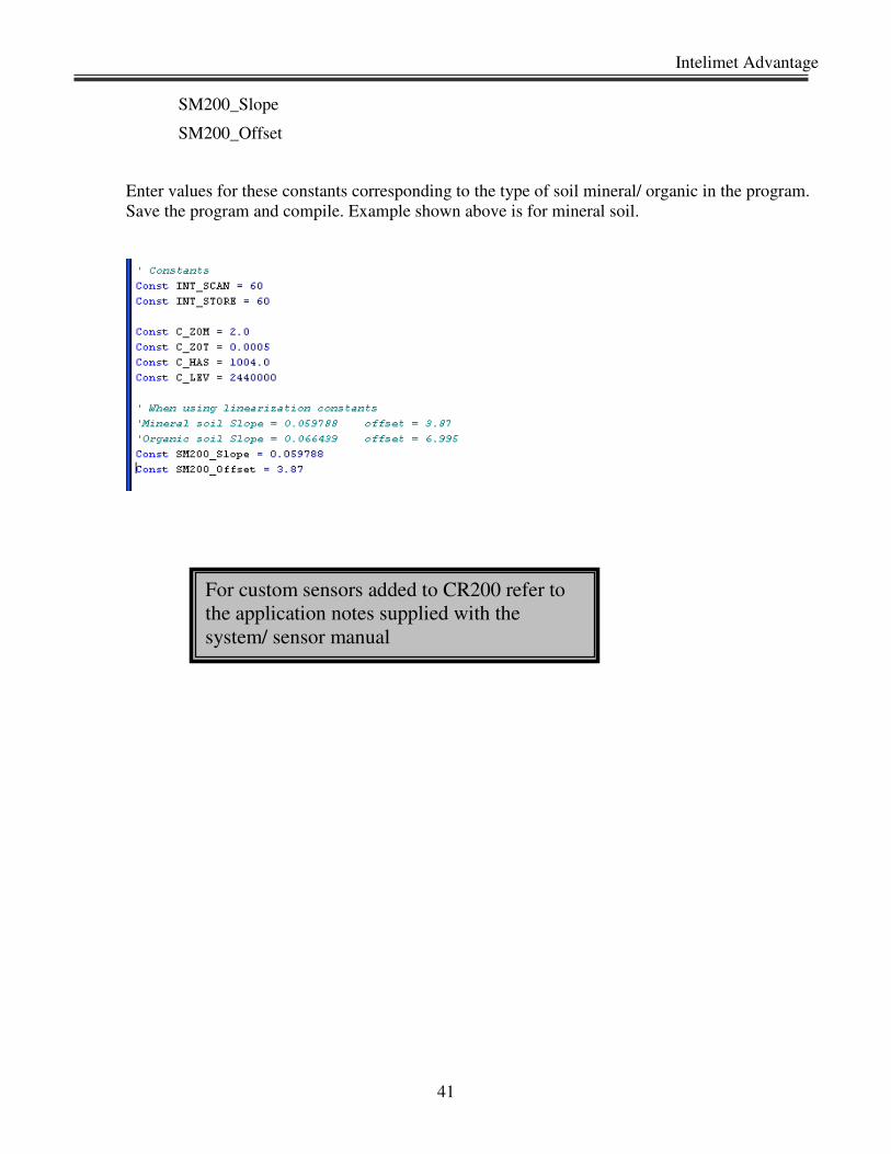
Identify the type of soil and corresponding slope and offset from the table above. Open the
program IMET_MP2_Main.CR2 or other program if saved in a different name in CRBasic.
Identify the SM200 constants at the top of the program after the system constants as shown below.
These constants are,
Intelimet Advantage
41
SM200_Slope
SM200_Offset
Enter values for these constants corresponding to the type of soil mineral/ organic in the program.
Save the program and compile. Example shown above is for mineral soil.
For custom sensors added to CR200 refer to
the application notes supplied with the
system/ sensor manual
Dynamax Inc
42
5.0 USING PC200w
5.1 Setup, Program Logger And Communications
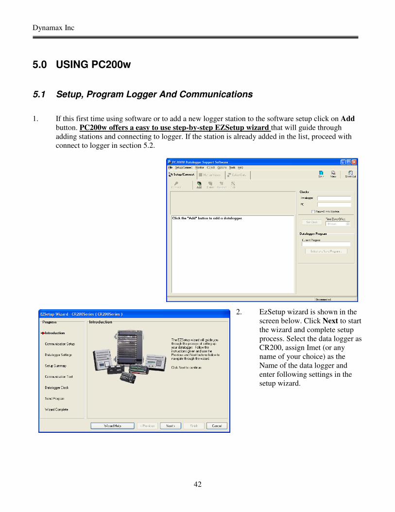
1. If this first time using software or to add a new logger station to the software setup click on Add
button. PC200w offers a easy to use step-by-step EZSetup wizard that will guide through
adding stations and connecting to logger. If the station is already added in the list, proceed with
connect to logger in section 5.2.
2. EzSetup wizard is shown in the
screen below. Click Next to start
the wizard and complete setup
process. Select the data logger as
CR200, assign Imet (or any
name of your choice) as the
Name of the data logger and
enter following settings in the
setup wizard.
Intelimet Advantage
43
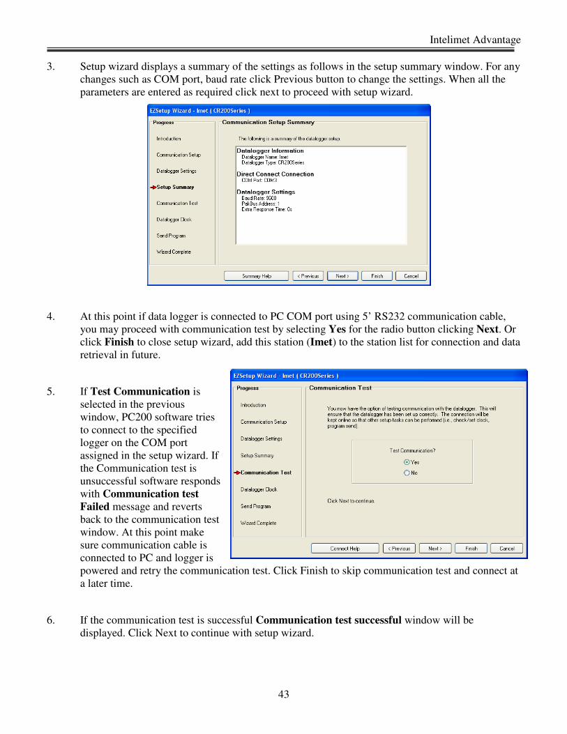
3. Setup wizard displays a summary of the settings as follows in the setup summary window. For any
changes such as COM port, baud rate click Previous button to change the settings. When all the
parameters are entered as required click next to proceed with setup wizard.
4. At this point if data logger is connected to PC COM port using 5’ RS232 communication cable,
you may proceed with communication test by selecting Yes for the radio button clicking Next. Or
click Finish to close setup wizard, add this station (Imet) to the station list for connection and data
retrieval in future.
5. If Test Communication is
selected in the previous
window, PC200 software tries
to connect to the specified
logger on the COM port
assigned in the setup wizard. If
the Communication test is
unsuccessful software responds
with Communication test
Failed message and reverts
back to the communication test
window. At this point make
sure communication cable is
connected to PC and logger is
powered and retry the communication test. Click Finish to skip communication test and connect at
a later time.
6. If the communication test is successful Communication test successful window will be
displayed. Click Next to continue with setup wizard.
Dynamax Inc
44
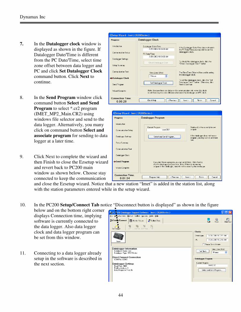
7. In the Datalogger clock window is
displayed as shown in the figure. If
Datalogger Date/Time is different
from the PC Date/Time, select time
zone offset between data logger and
PC and click Set Datalogger Clock
command button. Click Next to
continue.
8. In the Send Program window click
command button Select and Send
Program to select *.cr2 program
(IMET_MP2_Main.CR2) using
windows file selector and send to the
data logger. Alternatively, you many
click on command button Select and
associate program for sending to data
logger at a later time.
9. Click Next to complete the wizard and
then Finish to close the Ezsetup wizard
and revert back to PC200 main
window as shown below. Choose stay
connected to keep the communication
and close the Ezsetup wizard. Notice that a new station “Imet” is added in the station list, along
with the station parameters entered while in the setup wizard.
10. In the PC200 Setup/Connect Tab notice “Disconnect button is displayed” as shown in the figure
below and on the bottom right corner
displays Connection time, implying
software is currently connected to
the data logger. Also data logger
clock and data logger program can
be set from this window.
11. Connecting to a data logger already
setup in the software is described in
the next section.
Intelimet Advantage
45
5.2 Connect To Logger
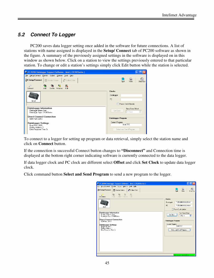
PC200 saves data logger setting once added in the software for future connections. A list of
stations with name assigned is displayed in the Setup/ Connect tab of PC200 software as shown in
the figure. A summary of the previously assigned settings in the software is displayed on in this
window as shown below. Click on a station to view the settings previously entered to that particular
station. To change or edit a station’s settings simply click Edit button while the station is selected.
To connect to a logger for setting up program or data retrieval, simply select the station name and
click on Connect button.
If the connection is successful Connect button changes to “Disconnect” and Connection time is
displayed at the bottom right corner indicating software is currently connected to the data logger.
If data logger clock and PC clock are different select Offset and click Set Clock to update data logger
clock.
Click command button Select and Send Program to send a new program to the logger.

Dynamax Inc
46
5.3 Monitor Data In Real Time
With communication established between software and the data logger, select Monitor Values tab
in PC200 window. This is similar to Numeric panel in PC208 and LoggerNet.
1. Click on Add button to open the signal list. Select Public from the left column to display public variables
available in the right column. Select desired signals from the right column. Click on a cell in the Monitor
values window, Click Paste button. All the selected signals will be displayed in the Monitor values
window. Note that if you have a long averaging interval, it will take that amount of time to see a new
reading. You may want to temporarily select a smaller interval or use maintenance program to test the
operation. And then download the program with required long term averaging interval later. Any unwanted
signals/ variables in Monitor window can be removed simply by selecting the cell and click Delete button.
2. Once in the Add menu, to select a range of values select the starting label, click on the beginning (for
example TCAir_C) and then a SHIFT-Click on the ending of the range (for example RG_mm) and then
click the Paste button.
3. Variable names are self explanatory with units. Any variable name starting with an “i” is an internal
variable or the raw data from the sensor. The same variable name without an “i” is the variable stored in the
logger.
4. Note any variables displaying a “-NAN” are out of range, or in the case of a sensor input location, it is a
open circuit wire.
5. In the figure below all Imet sensor variables are displayed in the monitor mode.
List of variable for
monitoring:
Time Stamp
Batt_V
SR_Wpm2
RG_mm
WindSpeed
WindDir
TAmbient
RH
BaroP
Dewpoint
Status
rootTSur_C
ETP_mm
Intelimet Advantage
47
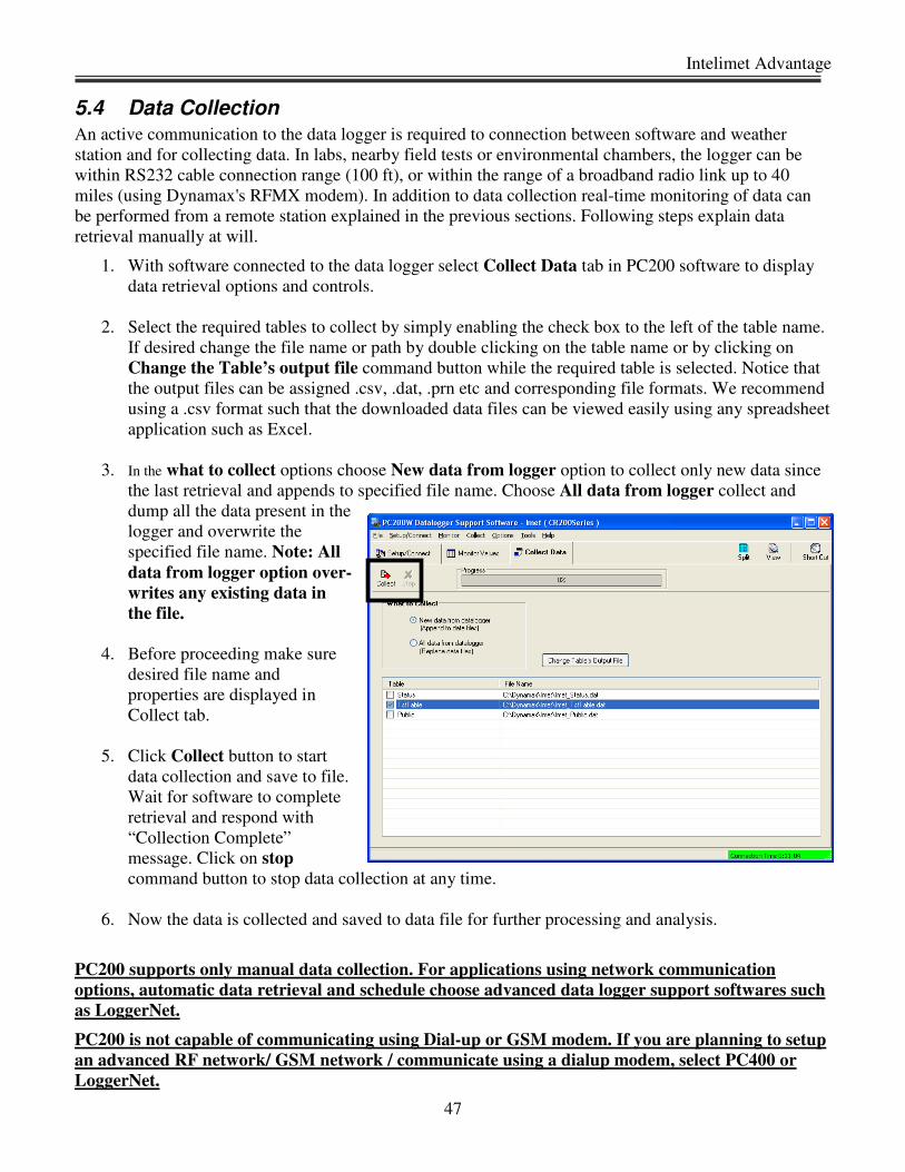
5.4 Data Collection
An active communication to the data logger is required to connection between software and weather
station and for collecting data. In labs, nearby field tests or environmental chambers, the logger can be
within RS232 cable connection range (100 ft), or within the range of a broadband radio link up to 40
miles (using Dynamax's RFMX modem). In addition to data collection real-time monitoring of data can
be performed from a remote station explained in the previous sections. Following steps explain data
retrieval manually at will.
1. With software connected to the data logger select Collect Data tab in PC200 software to display
data retrieval options and controls.
2. Select the required tables to collect by simply enabling the check box to the left of the table name.
If desired change the file name or path by double clicking on the table name or by clicking on
Change the Table’s output file command button while the required table is selected. Notice that
the output files can be assigned .csv, .dat, .prn etc and corresponding file formats. We recommend
using a .csv format such that the downloaded data files can be viewed easily using any spreadsheet
application such as Excel.
3. In the what to collect options choose New data from logger option to collect only new data since
the last retrieval and appends to specified file name. Choose All data from logger collect and
dump all the data present in the
logger and overwrite the
specified file name. Note: All
data from logger option over-
writes any existing data in
the file.
4. Before proceeding make sure
desired file name and
properties are displayed in
Collect tab.
5. Click Collect button to start
data collection and save to file.
Wait for software to complete
retrieval and respond with
“Collection Complete”
message. Click on stop
command button to stop data collection at any time.
6. Now the data is collected and saved to data file for further processing and analysis.
PC200 supports only manual data collection. For applications using network communication
options, automatic data retrieval and schedule choose advanced data logger support softwares such
as LoggerNet.
PC200 is not capable of communicating using Dial-up or GSM modem. If you are planning to setup
an advanced RF network/ GSM network / communicate using a dialup modem, select PC400 or
LoggerNet.

Dynamax Inc
48
6.0 DATA FORMAT, VIEW AND GRAPHS
This section discusses in detail
o File formats
o Data formats
o Open data file using VIEW, Plot signals
o Open data file using Excel, Plot signals
As explained in the previous chapter section, “Collect data for offline processing”, the tables
(files) of interest to the end-user is only,
Out Table………… saved in………… Imet_OutTable.csv
6.1 File Format
As explained in the previous chapter, section “Data Collection”, Intelimet Advantage data files can be
saved with the .csv, .dat, .txt, .prn extensions. Comma separated (.csv) is the recommended file format as
it allows the files to be viewed using any of the spreadsheet applications such as Excel. Here is a list of
some of the key differences among the file formats.
. csv Data points with in a line are delimited by a comma. Simply open the file in Excel to view
the data in a more readable format in rows and columns.

Intelimet Advantage
49
6.2 Data Format
Data collected from Intelimet Advantage is in one file /table as shown below. Files is saved with a
header showing the logger type, column header/ variable name.
Out Table………… saved in………… Imet_OutTable.csv
Out Table file contains average sensors measurements averaged over the storage interval along with
calculated Dew Point in degC, calculated Surface temperature in degC using iterative RCM algorithm,
calculated ETP using Lascano-VanBavel recursive algorithm. Custom sensors such as quantum sensor,
soil moisture and soil temperature also are stored in the output table. Below is the sequence of variables in
the output file from standard program.
Output Table Format:
Time Stamp
Record #
Batt_V
SR_Wpm2
RG_mm
Wind Vector (Speed, Direction, SD)
TAmbient
RH
BaroP
Dewpoint
Status
rootTSur_C
ETP_mm
Dynamax Inc
50
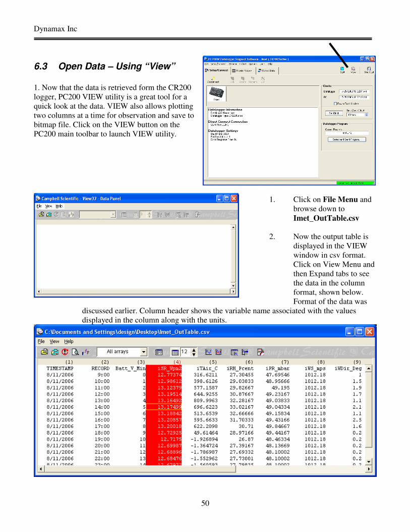
6.3 Open Data – Using “View”
1. Now that the data is retrieved form the CR200
logger, PC200 VIEW utility is a great tool for a
quick look at the data. VIEW also allows plotting
two columns at a time for observation and save to
bitmap file. Click on the VIEW button on the
PC200 main toolbar to launch VIEW utility.
1. Click on File Menu and
browse down to
Imet_OutTable.csv
2. Now the output table is
displayed in the VIEW
window in csv format.
Click on View Menu and
then Expand tabs to see
the data in the column
format, shown below.
Format of the data was
discussed earlier. Column header shows the variable name associated with the values
displayed in the column along with the units.
Intelimet Advantage
51
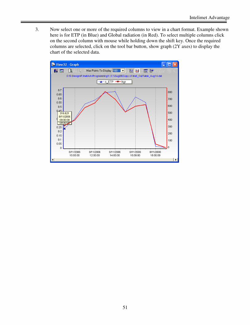
3. Now select one or more of the required columns to view in a chart format. Example shown
here is for ETP (in Blue) and Global radiation (in Red). To select multiple columns click
on the second column with mouse while holding down the shift key. Once the required
columns are selected, click on the tool bar button, show graph (2Y axes) to display the
chart of the selected data.
Dynamax Inc
52
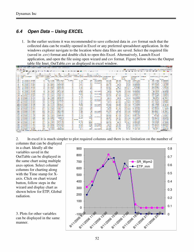
6.4 Open Data – Using EXCEL
1. In the earlier sections it was recommended to save collected data in .csv format such that the
collected data can be readily opened in Excel or any preferred spreadsheet application. In the
windows explorer navigate to the location where data files are saved. Select the required file
(saved in .csv) format and double click to open this Excel. Alternatively, Launch Excel
application, and open the file using open wizard and csv format. Figure below shows the Output
table file Imet_OutTable.csv as displayed in excel window.
2. In excel it is much simpler to plot required columns and there is no limitation on the number of
columns that can be displayed
in a chart. Ideally all the
variables saved in the
OutTable can be displayed in
the same chart using multiple
axes option. Select column/
columns for charting along
with the Time stamp for X-
axis. Click on chart wizard
button, follow steps in the
wizard and display chart as
shown below for ETP, Global
radiation.
3. Plots for other variables
can be displayed in the same
manner.
-100
0
100
200
300
400
500
600
700
800
900
8/11
/200
6 9:
00
8/11
/200
6 11
:00
8/11
/200
6 13
:00
8/11
/200
6 15
:00
8/11
/200
6 17
:00
8/11
/200
6 19
:00
8/11
/200
6 21
:00
8/11
/200
6 23
:00 0
0.1
0.2
0.3
0.4
0.5
0.6
0.7
0.8
SR_Wpm2
ETP_mm
Intelimet Advantage
53
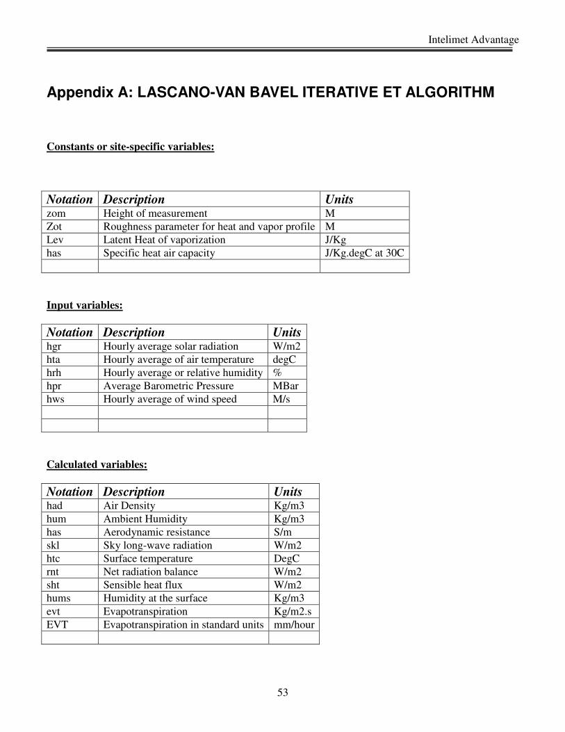
Appendix A: LASCANO-VAN BAVEL ITERATIVE ET ALGORITHM
Constants or site-specific variables:
Notation Description Units zom Height of measurement M
Zot Roughness parameter for heat and vapor profile M
Lev Latent Heat of vaporization J/Kg
has Specific heat air capacity J/Kg.degC at 30C
Input variables:
Notation Description Units hgr Hourly average solar radiation W/m2
hta Hourly average of air temperature degC
hrh Hourly average or relative humidity %
hpr Average Barometric Pressure MBar
hws Hourly average of wind speed M/s
Calculated variables:
Notation Description Units had Air Density Kg/m3
hum Ambient Humidity Kg/m3
has Aerodynamic resistance S/m
skl Sky long-wave radiation W/m2
htc Surface temperature DegC
rnt Net radiation balance W/m2
sht Sensible heat flux W/m2
hums Humidity at the surface Kg/m3
evt Evapotranspiration Kg/m2.s
EVT Evapotranspiration in standard units mm/hour

Dynamax Inc
54
RCM ET Algorithm:
( )( )5.0817.3
6
2.1013
)(10002361.0501.2
:
−⋅−⋅=
⋅⋅−=
Eelfeabp
onlyreferenceforheregivenhtalev
VariablesSpecificSite
Note: abp is measured by the InteliMet Advantage, so no calculation is needed.
( )
( )
−
⋅
=
⋅=
⋅=
+
⋅
1078.6ln2693882.17
1078.6ln3.237
1078.6
:int
3.237
2693882.17
a
a
asa
T
T
as
e
e
hdp
hrhTee
eTe
nCalculatioPoDew
a
a
( )
+
+⋅
⋅⋅+⋅+⋅−=
<+⋅
=⋅
=
+⋅=
⋅=
2.273
1500
4
22
237269.17
08241.070.0()2.273(867.5
1.01.016.0
ln
16.0
ln
2.273323.1
2.10131548.1
:lg
hta
hdp
hdp
ehumhtaEskl
hwswhenhws
zot
zom
rasorhws
zot
zom
ras
hdp
ehum
abphad
ncalculatioETfororithmaRCM
( ) ( )
( )
+
⋅⋅⋅
⋅
−+
⋅
−⋅+
⋅⋅⋅−+++⋅−−⋅=
+⋅
=
htc
hta
hashad
raslev
ras
humhtc
e
rashta
hashadhtchtasklhtcEhgrroothtc
htc
htchtc
,
2.273
16.303
2.273323.1
2.273
16.303)2.273(867.580.0
237269.17
4
10
( )( )( )
( )
3600
2.273
16.303
2.273867.580.04
⋅=
+=
⋅+
−⋅⋅⋅=
++⋅−−⋅=
evtEVT
lev
shtrntevt
rashta
htchtahashadsht
sklhtcEhgrrnt
Intelimet Advantage
55
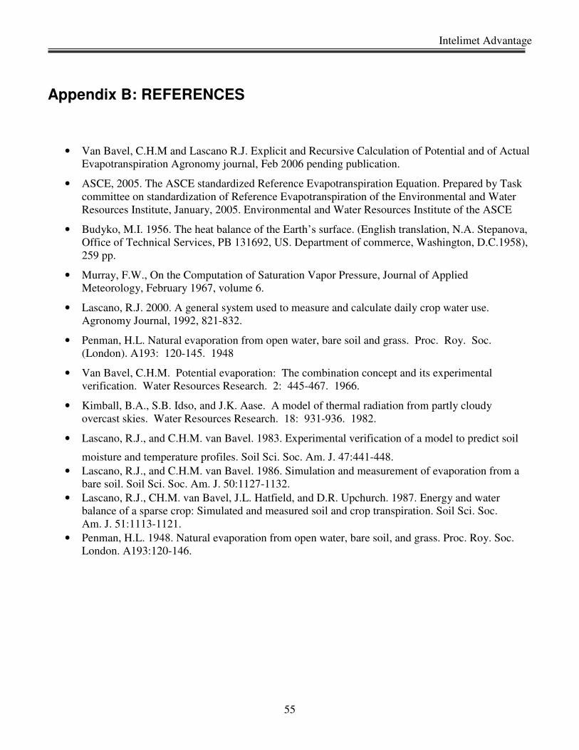
Appendix B: REFERENCES
• Van Bavel, C.H.M and Lascano R.J. Explicit and Recursive Calculation of Potential and of Actual
Evapotranspiration Agronomy journal, Feb 2006 pending publication.
• ASCE, 2005. The ASCE standardized Reference Evapotranspiration Equation. Prepared by Task
committee on standardization of Reference Evapotranspiration of the Environmental and Water
Resources Institute, January, 2005. Environmental and Water Resources Institute of the ASCE
• Budyko, M.I. 1956. The heat balance of the Earth’s surface. (English translation, N.A. Stepanova,
Office of Technical Services, PB 131692, US. Department of commerce, Washington, D.C.1958),
259 pp.
• Murray, F.W., On the Computation of Saturation Vapor Pressure, Journal of Applied
Meteorology, February 1967, volume 6.
• Lascano, R.J. 2000. A general system used to measure and calculate daily crop water use.
Agronomy Journal, 1992, 821-832.
• Penman, H.L. Natural evaporation from open water, bare soil and grass. Proc. Roy. Soc.
(London). A193: 120-145. 1948
• Van Bavel, C.H.M. Potential evaporation: The combination concept and its experimental
verification. Water Resources Research. 2: 445-467. 1966.
• Kimball, B.A., S.B. Idso, and J.K. Aase. A model of thermal radiation from partly cloudy
overcast skies. Water Resources Research. 18: 931-936. 1982.
• Lascano, R.J., and C.H.M. van Bavel. 1983. Experimental verification of a model to predict soil
moisture and temperature profiles. Soil Sci. Soc. Am. J. 47:441-448.
• Lascano, R.J., and C.H.M. van Bavel. 1986. Simulation and measurement of evaporation from a
bare soil. Soil Sci. Soc. Am. J. 50:1127-1132.
• Lascano, R.J., CH.M. van Bavel, J.L. Hatfield, and D.R. Upchurch. 1987. Energy and water
balance of a sparse crop: Simulated and measured soil and crop transpiration. Soil Sci. Soc.
Am. J. 51:1113-1121.
• Penman, H.L. 1948. Natural evaporation from open water, bare soil, and grass. Proc. Roy. Soc.
London. A193:120-146.

Dynamax Inc
56
Appendix C: DATA SHEETS