Embed Size (px)
Citation preview
Immersive Visualization and InteractiveAnalysis of Ground Penetrating Radar Data
Matthew R. Sgambati1, Steven Koepnick1, Daniel S. Coming?1,Nick Lancaster1, and Frederick C. Harris, Jr.2
1Desert Research Institute2Department of Computer Science and Engineering, University of Nevada, Reno
Abstract. Ground Penetrating Radar is a geophysical technique forobtaining information about sub-surface earth materials. Geologists usethe data collected to obtain a view of terrain underground. This data istypically viewed using a desktop interface where the user usually inter-acts using a keyboard and mouse. Visualizing the data in a slice by slice2D format can be difficult to interpret. Instead, we created a programfor an immersive visualization environment that uses tracked input de-vices. This is done using real-time, stereoscopic, perspective-corrected,slice-based volume rendering. To aid with the visualization the user canmodify the display of the volume using integrated tools, such as transferfunctions, lighting, and color maps. Users are also given data analy-sis tools to take application-specific measurements such as dip, strike,other angles, and distances in 3D. Compared to typical desktop inter-face interactions, the 6-degree of freedom user interface provided by theimmersive visualization environment makes it notably easier to performthe application-specific measurements.
1 Introduction
Ground Penetrating Radar (GPR) [1] is a geophysical technique used in suchfields as archaeology, environmental site characterization, hydrology, sedimentol-ogy, and glaciology to obtain 3-D information about subsurface earth materialswithout the expense and difficulty of excavation or drilling [2].
The data gathered by GPR requires special software in order to be visualizedas 2D slice data or a 3D volume. There are many software programs that visualizeGPR data [3–8]; however, these applications have not been developed to displayGPR data in an immersive visualization environment (IVE) with tracked inputdevices. IVEs allow the user to view the data in ways that desktop displaysare not capable of, such as being able to view around the data and behind itwithout moving the data. Geologists also need to analyze it, including takingmeasurements of the thickness and orientation (dip and strike) of sedimentaryunits. Desktop tools are typically limited to the interactions provided by inputdevices designed for 2D interfaces, while tools created for an IVE can use itstracking abilities, providing a different way to interact with the data.
? {sgambati, koepnick, dcoming, nick}@dri.edu, [email protected]
2 M.R. Sgambati, S. Koepnick, D.S. Coming, N. Lancaster, & F.C. Harris, Jr.
We present an immersive application for visualizing GPR and other seismicdata with topographic correction and a surface for context, and we introduceinteractive analysis tools for exploring and measuring this data and visualizingthe dip and strike (surface orientation) of structures. Further, we integrate thesetools and other improvements into an open-source immersive volume visualiza-tion application called Toirt-Samhlaigh [9].
2 Related Work
Tools exist for analyzing and viewing GPR data on desktop computers. GPR-SLICE [5] creates 2D and 3D displays of GPR data and includes many tools,such as isosurfaces and topographic correction. Ground Vision and Easy 3D [6]support acquisition and visualization of GPR data. Another program called Easy3D [7] visualizes data in 3D from a single channel or multi channel GPR systemand provides viewing tools, such as filtering. Geoprobe [8] provides many tools toaid viewing and analysis of 3D GPR data, like multi-threaded volume attributecalculations and dynamic calculation and display of horizon-based attributes.These tools do not leverage immersive displays or 3D interaction.
There are, however, immersive tools that visualize volumetric data, some ofwhich support geological data [10–16]. Ropinski et al. [10] used a table display toexplore seismic volume datasets using context and focus visualization metaphors.Visualizer [11] supports isosurface and streamline creation, slice visualization,and custom tools. Chopra et al. [12] visualized large-scale seismic simulations bysimplifying, sampling, and filtering, and supported surface rendering.
Other immersive volumetric tools use geometric representations of data, likeisosurfaces and slices. Winkler et al. [13] extended a standard geoscience pro-gram to an immersive environment and displayed the desktop interface on avirtual surface. Frohlich et al. [14] let users immersively examine geo-scientificdata (seismic volumes and well logs) using a prop based interation device and asonification technique. Dorn et al. [15] presented a system for platform and wellplanning in an immersive environment, which imported and displayed surfaceand subsurface data. LaFayette et al. [16] visualized a GPR scan of an anthill byconstructing an isosurface on the boundary between soil and air. CoRSAIRe [17]provides analysis of a fluid dataset using isosurface rendering of a simple surface,with haptic feedback according to an invisible isosurface.
Other immersive systems have dealt with measurement tools. Kreylos et al.described their immersive LiDAR tool [18], which could measure distances andangles in 3D space. Hagedorn et al. let users measure objects in an IVE [19],using line, cylinder, and ellipsoid tools.
Our system visualizes large volumetric datasets, including topographicallycorrected GPR data, in an immersive environment. We provide interaction toolsto make generic and GPR-specific measurements, such as dip, strike, and dis-tance. Existing tools lack the means to measure dip and strike of features insubsurface geophysical data such as GPR. We also visualize these measurements,as well as the ground surface.
Lecture Notes in Computer Science 3
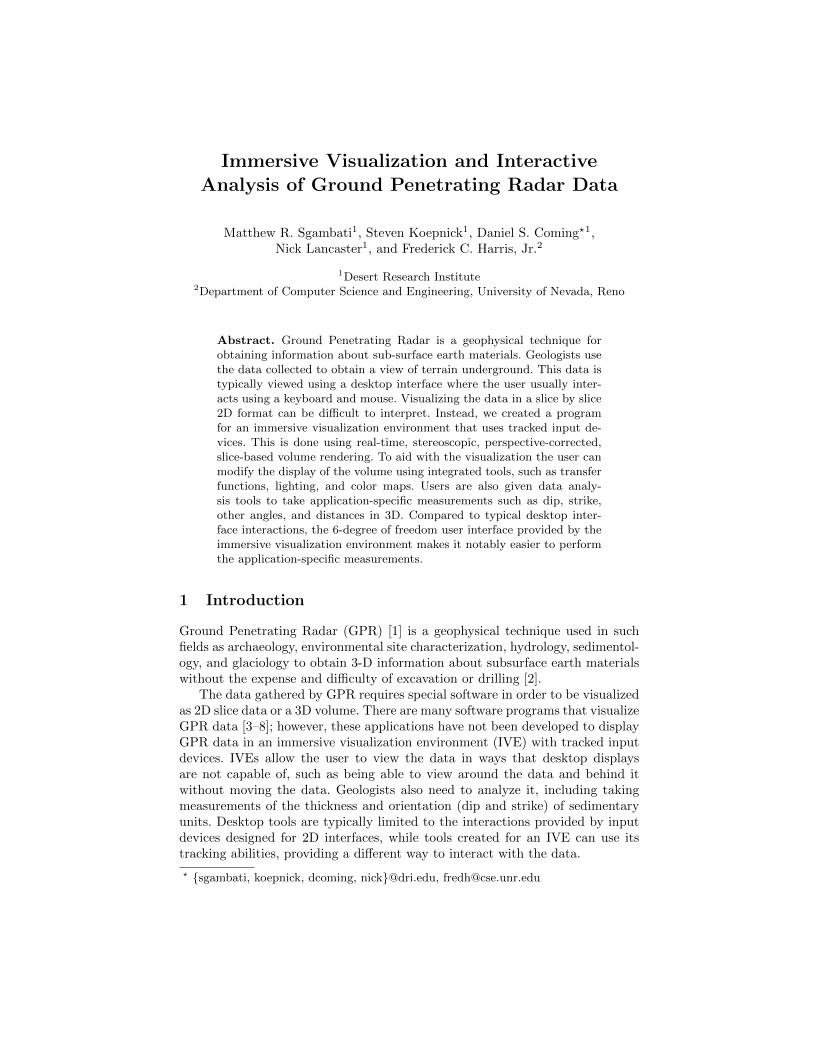
(a) (b) (c)
Fig. 1. (a) Researchers use a GPR unit on a sand dune to send (b) GPR pulses throughthe ground, reflecting off surfaces [21] and, after generating many samples, create (c)2D subsurface profiles [22].
3 Background
3.1 Ground Penetrating Radar
GPR uses the propagation of electromagnetic waves that respond to changesin the electromagnetic properties of subsurface materials. A GPR unit typicallyconsists of transmitting and a receiving antennae to send and receive pulsesinto the ground, shown in Fig. 1(a). The ways in which this energy is reflectedand scattered off surfaces and objects are expressed by the relative permitivitycontrast between the target and the background. GPR surveys can provide in-formation on the stratigraphic architecture, geometry, and correlation and quan-tification of sedimentary structures [1].
As seen in Fig. 1(b), as the waves leave the transmitter and travel throughthe ground they reflect off of subsurface structures. The receiver then detectsthe reflected waves and records the information. These pulses not only reflectoff of objects in the subsurface, including cracks and voids, but also reflect off ofmaterials with different dielectric properties. This means that GPR can detectsubsurface features along with changes in the type of subsurface material toprovide a map of the variation in ground electrical properties [20].
A field GPR survey to gather data is typically performed in a grid pattern. Aresearcher moves along this grid with GPR equipment, taking readings at eachgrid point. Fig. 1(c) shows an example GPR profile gathered on a sand dune.
3.2 Application of GPR to studies of sand dunes
Sand dunes provide a favorable target for GPR studies because they have ahigh resistivity, which allows for good penetration of electromagnetic energyand they contain large-scale sedimentary structures that can be resolved byGPR [22]. Documenting and analyzing these sedimentary structures is importantfor understanding sand dune development and provides information on pastclimates and wind directions. Deposits of ancient sand dunes also occur in therock record. Many of these ancient aeolian sandstones are important reservoirsfor hydrocarbons [23].
Characterizing the sediments of modern sand dunes in order to understandthe conditions in which they formed requires measurements of the angle and
4 M.R. Sgambati, S. Koepnick, D.S. Coming, N. Lancaster, & F.C. Harris, Jr.
(a) (b)
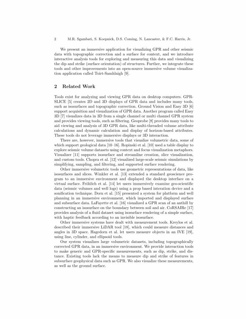
Fig. 2. (a) A Brunton Compass [24] measures dip and strike, illustrated in (b) [25].
direction of dip of primary and secondary sedimentary structures in order todetermine the wind directions that formed them. Measurements of the thicknessof sedimentary units are also frequently needed. In field studies, dip and strike ofbeds are measured using a Brunton Compass. These measurements are, however,hard to make using existing GPR visualization software packages.
3.3 Brunton Compass
A Brunton Compass, shown in Fig. 2(a), is a tool used by geologists to determinethe dip and strike angles of surfaces. The angle of dip is a measure of the surface’ssteepness relative to horizontal along its gradient. The angle of strike describesthe orientation of the surface relative to North. The strike is measured using thestrike line, a line on the surface that represents the intersection of a horizontalplane with the surface. The dip is measured using the steepest gradient from thestrike line. Another way to represent strike is to use the dip direction, which isthe gradient used for the dip measurement projected onto the horizontal surfacethat is used to create the strike line. This means that the dip direction is always90 degrees off the strike line (Fig. 2(b)).
4 Application Design
Our goal was to improve available tools for geologists to visualize and analyzedata from GPR studies of sand dunes. With a geologist, we identified severalformal requirements for the tool: (a) visualize a 3D “data cube” comprising astack of 2D profiles in Society of Exploration Geophysicists (SEG) Y [26] dataformat; (b) correct data alignment for topography; (c) collect dip/strike anddistance measurements from the volume; (d) visualize dip/strike measurements.
We kept a few special considerations in mind, regarding GPR measurementsof sand dune subsurfaces. The subsurface is fairly homogeneous, with slight vari-ations mostly due to moisture content. These slight variations are what geologistsare interested in. Therefore, we don’t expect to find easily segmentable featuresbut rather want to leverage the domain knowledge that geologists have alreadydeveloped in looking at 2D transects of sand dunes.
Lecture Notes in Computer Science 5
We designed our application for use on several systems from CAVE [27] styledisplays to 3DTV-based displays. We assume stereoscopic perspective-correctedrendering based on head-tracking and a six degree-of-freedom input device withseveral buttons. We built our application on Toirt-Samhlaigh [9, 28], a volumerendering application that performs slice-based volume rendering [29] on 3Dtextures with bricking and an octree acceleration structure [30]. It has 1D and2D transfer functions to map data values to colors and opacities. It has goodsupport for both immersive displays and desktops and was built on the VirtualReality User Interface (Vrui) [31] VR toolkit. Because Vrui abstracts the displaysand input devices, our efforts focused on processing GPR data, analysis toolsfor GPR data, and ensuring that interface design decisions would work well oneach system. Vrui provides an integrated user interface API with widgets andmenus which work on both immersive and desktop systems.
While designing our application, we strove to follow the following designprinciples: (a) target the interface to the user domain; (b) provide methodsto explore data, extract measurements, and see focus in context; (c) minimizephysical fatigue of the user interface; (d) design for wide variety of immersivedisplays and when possible, for non-immersive displays.
5 Visualizing GPR data
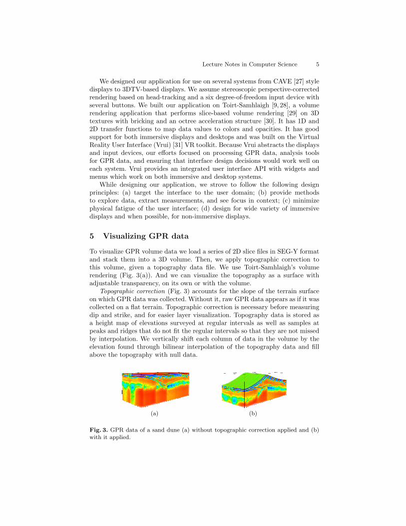
To visualize GPR volume data we load a series of 2D slice files in SEG-Y formatand stack them into a 3D volume. Then, we apply topographic correction tothis volume, given a topography data file. We use Toirt-Samhlaigh’s volumerendering (Fig. 3(a)). And we can visualize the topography as a surface withadjustable transparency, on its own or with the volume.
Topographic correction (Fig. 3) accounts for the slope of the terrain surfaceon which GPR data was collected. Without it, raw GPR data appears as if it wascollected on a flat terrain. Topographic correction is necessary before measuringdip and strike, and for easier layer visualization. Topography data is stored asa height map of elevations surveyed at regular intervals as well as samples atpeaks and ridges that do not fit the regular intervals so that they are not missedby interpolation. We vertically shift each column of data in the volume by theelevation found through bilinear interpolation of the topography data and fillabove the topography with null data.
(a) (b)
Fig. 3. GPR data of a sand dune (a) without topographic correction applied and (b)with it applied.
6 M.R. Sgambati, S. Koepnick, D.S. Coming, N. Lancaster, & F.C. Harris, Jr.
(a) (b)
Fig. 4. Surface visualization for a topographically correct GPR dataset with (a) notransparency and (b) 50% transparency (with a different transfer function).
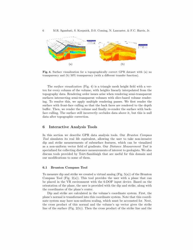
The surface visualization (Fig. 4) is a triangle mesh height field with a ver-tex for every column of the volume, with heights linearly interpolated from thetopography data. Rendering order issues arise when rendering semi-transparentsurfaces intersecting semi-transparent volumes with slice-based volume render-ing. To resolve this, we apply multiple rendering passes. We first render thesurface with front-face culling so that the back faces are rendered to the depthbuffer. Then, we render the volume and finally re-render the surface with back-face culling. The surface still incorrectly occludes data above it, but this is nulldata after topographic correction.
6 Interactive Analysis Tools
In this section we describe GPR data analysis tools. Our Brunton CompassTool simulates its real life equivalent, allowing the user to take non-invasivedip and strike measurements of subsurface features, which can be visualizedas a non-uniform vector field of gradients. Our Distance Measurement Tool isspecialized for collecting distance measurements of interest to geologists. We alsodiscuss tools provided by Toirt-Samhlaigh that are useful for this domain andour modifications to some of them.
6.1 Brunton Compass Tool
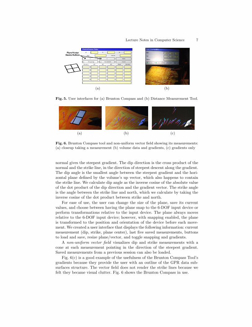
To measure dip and strike we created a virtual analog (Fig. 5(a)) of the BruntonCompass Tool (Fig. 2(a)). This tool provides the user with a plane that canbe placed in the VR environment with the 6-DOF input device. Based on theorientation of the plane, the user is provided with the dip and strike, along withthe coordinates of the plane’s center.
Dip and strike are calculated in the volume’s coordinate system. First, theplane’s normal is transformed into this coordinate system. Note that this coordi-nate system may have non-uniform scaling, which must be accounted for. Next,the cross product of this normal and the volume’s up vector gives the strikeline of the surface (Fig. 2(b)). Then the cross product of the strike line and the
Lecture Notes in Computer Science 7
(a) (b)
Fig. 5. User interfaces for (a) Brunton Compass and (b) Distance Measurement Tool.
(a) (b) (c)
Fig. 6. Brunton Compass tool and non-uniform vector field showing its measurements:(a) closeup taking a measurement (b) volume data and gradients, (c) gradients only
normal gives the steepest gradient. The dip direction is the cross product of thenormal and the strike line, in the direction of steepest descent along the gradient.The dip angle is the smallest angle between the steepest gradient and the hori-zontal plane defined by the volume’s up vector, which also happens to containthe strike line. We calculate dip angle as the inverse cosine of the absolute valueof the dot product of the dip direction and the gradient vector. The strike angleis the angle between the strike line and north, which we calculate by taking theinverse cosine of the dot product between strike and north.
For ease of use, the user can change the size of the plane, save its currentvalues, and choose between having the plane snap to the 6-DOF input device orperform transformations relative to the input device. The plane always movesrelative to the 6-DOF input device; however, with snapping enabled, the planeis transformed to the position and orientation of the device before each move-ment. We created a user interface that displays the following information: currentmeasurement (dip, strike, plane center), last five saved measurements, buttonsto load and save, resize plane/vector, and toggle snapping and gradients.
A non-uniform vector field visualizes dip and strike measurements with acone at each measurement pointing in the direction of the steepest gradient.Saved measurements from a previous session can also be loaded.
Fig. 6(c) is a good example of the usefulness of the Brunton Compass Tool’sgradients because they provide the user with an outline of the GPR data sub-surfaces structure. The vector field does not render the strike lines because wefelt they became visual clutter. Fig. 6 shows the Brunton Compass in use.
8 M.R. Sgambati, S. Koepnick, D.S. Coming, N. Lancaster, & F.C. Harris, Jr.
(a) (b)
Fig. 7. 1D Transfer Function editors: (a) piecewise-linear and (b) multiple Gaussians.
Fig. 8. Lighting being applied to GPR data with the lighting interface.
6.2 Distance Measurement Tool
To measure distances between points in 3D space, we reinvented the DistanceMeasurement Tool (Fig. 5(b)). VRUI provides a distance measurement tool, butupon initial testing, the geologist testing our system felt the interface providedtoo many options and too much information, and requested a version specializedto measurements relative to GPR. In our tool, the user creates start and endpoints using the 6-DOF input device to take a measurement. A marker is drawnat each point along with a connecting line segment. The user may opt to addlabels to measurements when saving them: horizontal x, horizontal y, or verticalz. The following information is displayed on the tool’s interface: start/end point,distance, buttons for labels, and a ’Save’ button to save measurements to file.
6.3 Toirt-Samhlaigh Tools
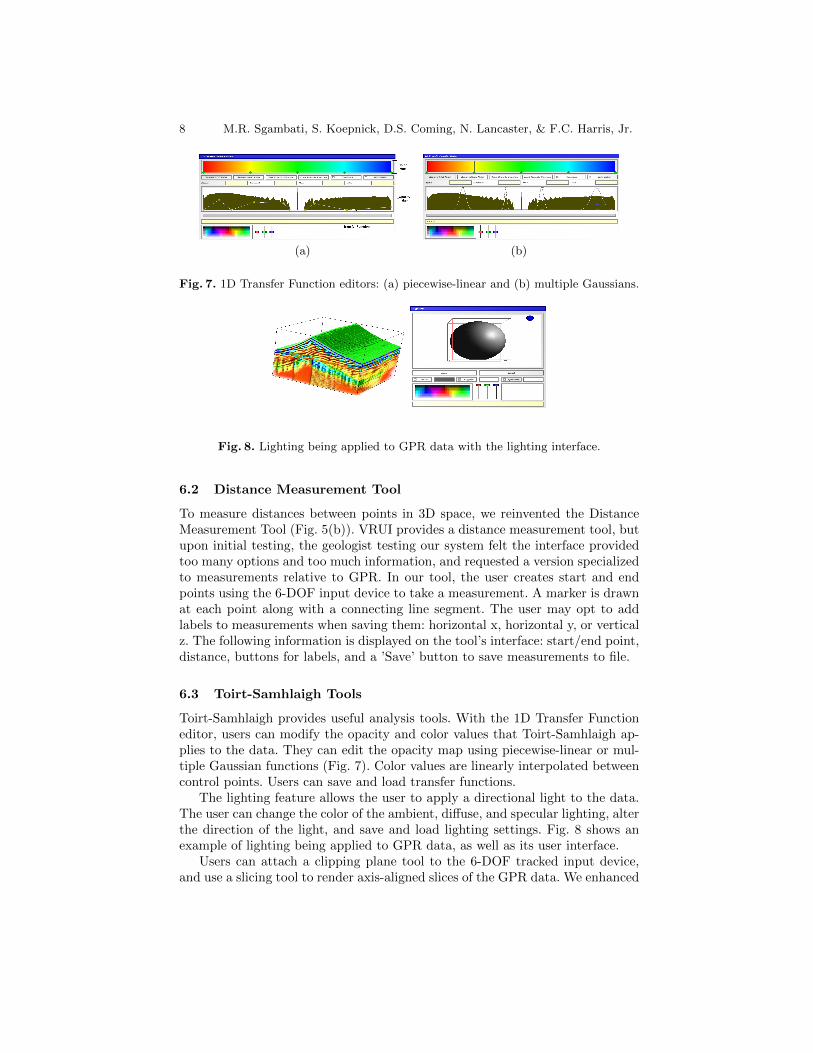
Toirt-Samhlaigh provides useful analysis tools. With the 1D Transfer Functioneditor, users can modify the opacity and color values that Toirt-Samhlaigh ap-plies to the data. They can edit the opacity map using piecewise-linear or mul-tiple Gaussian functions (Fig. 7). Color values are linearly interpolated betweencontrol points. Users can save and load transfer functions.
The lighting feature allows the user to apply a directional light to the data.The user can change the color of the ambient, diffuse, and specular lighting, alterthe direction of the light, and save and load lighting settings. Fig. 8 shows anexample of lighting being applied to GPR data, as well as its user interface.
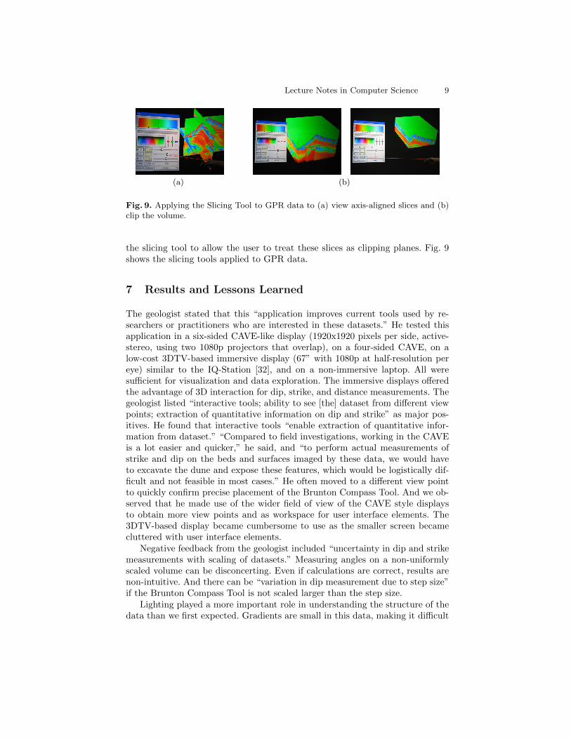
Users can attach a clipping plane tool to the 6-DOF tracked input device,and use a slicing tool to render axis-aligned slices of the GPR data. We enhanced
Lecture Notes in Computer Science 9
(a) (b)
Fig. 9. Applying the Slicing Tool to GPR data to (a) view axis-aligned slices and (b)clip the volume.
the slicing tool to allow the user to treat these slices as clipping planes. Fig. 9shows the slicing tools applied to GPR data.
7 Results and Lessons Learned
The geologist stated that this “application improves current tools used by re-searchers or practitioners who are interested in these datasets.” He tested thisapplication in a six-sided CAVE-like display (1920x1920 pixels per side, active-stereo, using two 1080p projectors that overlap), on a four-sided CAVE, on alow-cost 3DTV-based immersive display (67” with 1080p at half-resolution pereye) similar to the IQ-Station [32], and on a non-immersive laptop. All weresufficient for visualization and data exploration. The immersive displays offeredthe advantage of 3D interaction for dip, strike, and distance measurements. Thegeologist listed “interactive tools; ability to see [the] dataset from different viewpoints; extraction of quantitative information on dip and strike” as major pos-itives. He found that interactive tools “enable extraction of quantitative infor-mation from dataset.” “Compared to field investigations, working in the CAVEis a lot easier and quicker,” he said, and “to perform actual measurements ofstrike and dip on the beds and surfaces imaged by these data, we would haveto excavate the dune and expose these features, which would be logistically dif-ficult and not feasible in most cases.” He often moved to a different view pointto quickly confirm precise placement of the Brunton Compass Tool. And we ob-served that he made use of the wider field of view of the CAVE style displaysto obtain more view points and as workspace for user interface elements. The3DTV-based display became cumbersome to use as the smaller screen becamecluttered with user interface elements.
Negative feedback from the geologist included “uncertainty in dip and strikemeasurements with scaling of datasets.” Measuring angles on a non-uniformlyscaled volume can be disconcerting. Even if calculations are correct, results arenon-intuitive. And there can be “variation in dip measurement due to step size”if the Brunton Compass Tool is not scaled larger than the step size.
Lighting played a more important role in understanding the structure of thedata than we first expected. Gradients are small in this data, making it difficult
10 M.R. Sgambati, S. Koepnick, D.S. Coming, N. Lancaster, & F.C. Harris, Jr.
to obtain depth cues from occlusion or parallax (stereo or motion). With lightingapplied, the increased visual gradient provided its own depth cues and increasedthe visual difference between nearby viewpoints, improving effectiveness of theother depth cues. Interacting with the lighting tool also provides structural cuesas shading on surfaces changes.
The geologist had difficulty using a pointer to interact with small (2”) 2Dwidgets just out of reach, but he was adept at placing and orienting the virtualbrunton compass. For example, when using immersive displays, the Gaussiantransfer function editor was much easier to use than the piece-wise linear transferfunction editor, because it required fewer precise selection actions by the user toobtain a desired function. Sliding the Gaussian around by its center was also aquick way to explore a new dataset for interesting features. Perhaps a 2D touchtablet would be better for these 2D widgets, but carrying it might cause fatigue.
The ability to log measurements while in the environment is crucial, in lieuof a notepad. Similarly important is saving and reloading as much of the systemstate as possible, whether to resume later or to show a colleague.
8 Conclusions
Existing tools for visualizing GPR data are bound by the limitations of a typicaldesktop display and input devices. We have presented a way of overcoming thelimitations of that environment by creating a system that successfully allows forthe visualization and interactive analysis of GPR datasets in an IVE.
In the IVE, the user can explore the data from arbitrary viewpoints by mov-ing around and inside the data. The tracked input devices provided the user withmore natural ways of interacting with the data than are possible with typicaldesktop displays and input devices, as seen in Section 7.
We created two immersive analysis tools which a geologist found very useful.The Distance Measurement Tool allows users to take specialized distance mea-surements, while the Brunton Compass Tool allows users to take dip and strikeangle measurements. The topographic correction and surface visualization helpthe user understand the shape of the terrain’s surface. Additionally, the systemprovides many techniques for the user to view and interact with the data, suchas changing its orientation and position, apply lighting, and transfer functions.
The system is not limited only to GPR data, however. Our enhancements toToirt-Samhlaigh can be applied to other data types. Also, saving and loadingfunctionality increases Toirt-Samhlaigh’s user friendliness.
9 Future Work
This system would benefit from more user friendliness. A menu should be createdto allow the selection of a data file to load or save. A tool to aid in data analysiscould restrict rendering of data to a user-defined shape. Another tool couldautomatically or semi-automatically segment the data into layers which the user
Lecture Notes in Computer Science 11
could then peel off. The last tool could generate isosurfaces to help visualize thestructure of the subsurfaces.
The ability to change the scale of the volume on any axis, quickly swapdatasets while the program is running, or render multiple volumes would beuseful. We would also like to support additional data file formats.
Finally, we plan to investigate bridging the gap between incorporating immer-sive visualization into scientific workflows and generating images for publication.
Acknowledgements
This work is funded by the U.S. Army’s RDECOM-STTC under Contract No.N61339-04-C-0072 at the Desert Research Institute. We would also like to thankPatrick O’Leary, author of Toirt-Samhlaigh, without which this work would nothave been possible, and Phil McDonald for his contributions to the SEG-Y dataloader.
References
1. Bristow, C., Jol, H.: An introduction to ground penetrating radar (GPR) in sedi-ments. Geological Society London Special Publications (211)1 (2003) 1–7
2. Jol, H., Bristow, C.: GPR in sediments: advice on data collection, basic process-ing and interpretation, a good practice guide. Geological Society London SpecialPublications (211)1 (2003) 9–27
3. Nuzzo, L., Leucci, G., Negri, S., Carrozzo, M., Quarta, T.: Application of 3Dvisualization techniques in the analysis of GPR data for archaeology. Annals ofGeophysics (45)2 (2009) 321–337
4. Sigurdsson, T., Overgaard, T.: Application of GPR for 3-D visualization of geo-logical and structural variation in a limestone formation. J. Applied Geophysics(40)1-3 (1998) 29–36
5. Goodman, D.: GPR-SLICE Software (2010) http://www.gpr-survey.com/.6. Mala GeoScience: Windows based acquisition and visualization software (2010)
http://www.idswater.com/water/us/mala_geoscience/data_acquisition_
software/85_0/g_supplier_5.html.7. AEGIS Instruments: Easy 3D - GPR Visualization Software (2010) http://www.
aegis-instruments.com/products/brochures/easy-3d-gpr.html.8. Halliburton: GeoProbe Volume Interpretation Software (2011) http://www.
halliburton.com/ps/Default.aspx?navid=220&pageid=842.9. O’Leary, P.: Toirt-Samhlaigh (2010) http://code.google.com/p/
toirt-samhlaigh/.10. Ropinski, T., Steinicke, F., Hinrichs, K.H.: Visual exploration of seismic volume
datasets. J. WSCG 14 (2006) 73–8011. Billen, M., Kreylos, O., Hamann, B., Jadamec, M., Kellogg, L., Staadt, O., Sum-
ner, D.: A geoscience perspective on immersive 3D gridded data visualization.Computers & Geosciences (34)9 (2008) 1056–1072
12. Chopra, P., Meyer, J., Fernandez, A.: Immersive volume visualization of seismicsimulations: A case study of techniques invented and lessons learned. In: IEEEVisualization. (2002) 497–500
12 M.R. Sgambati, S. Koepnick, D.S. Coming, N. Lancaster, & F.C. Harris, Jr.
13. Winkler, C., Bosquet, F., Cavin, X., Paul, J.: Design and implementation of animmersive geoscience toolkit. In: IEEE Visualization. (1999) 429–556
14. Frohlich, B., Barrass, S., Zehner, B., Plate, J., Gobel, M.: Exploring geo-scientificdata in virtual environments. In: IEEE Visualization. (1999) 169–173
15. Dorn, G., Touysinhthiphonexay, K., Bradley, J., Jamieson, A.: Immersive 3-Dvisualization applied to drilling planning. The Leading Edge (20)12 (2001) 1389–1392
16. LaFayette, C., Parke, F.I., Pierce, C.J., Nakamura, T., Simpson, L.: Atta texanaleafcutting ant colony: a view underground. In: ACM SIGGRAPH 2008 talks.(2008) 53:1
17. Katz, B., Warusfel, O., Bourdot, P., Vezien, J.: CoRSAIRe–Combination ofSensori-motor Rendering for the Immersive Analysis of Results. In: Proc. Intl.Workshop on Interactive Sonification, York, UK. Volume 3. (2007)
18. Kreylos, O., Bawden, G.W., Kellogg, L.H.: Immersive visualization and analysis ofLiDAR data. In: Proc. Intl. Symposium on Advances in Visual Computing. (2008)846–855
19. Hagedorn, J., Joy, P., Dunkers, S., Peskin, A., Kelso, J., Terrill, J.: MeasurementTools for the Immersive Visualization Environment: Steps Toward the Virtual Lab-oratory. J. Research of the National Institute of Standards and Technology (112)5(2007)
20. Griffin, S., Pippett, T.: Ground penetrating radar. Geophysical and Remote Sens-ing Methods for Regolith Exploration, CRC LEME Open File report 144 (2002)80–89
21. Subsurface Detection: Subsurface Detection. If it’s in the ground, we’ll find it.(2010) http://www.subsurface.com.au/GPR.html.
22. Bristow, C., Duller, G., Lancaster, N.: Age and dynamics of linear dunes in theNamib Desert. Geology (35)6 (2007) 555–558
23. Reading, H.: Sedimentary environments: processes, facies, and stratigraphy. Wiley-Blackwell, Oxford (1996)
24. Brunton Inc.: Brunton geo pocket transit (2010) http://www.brunton.com/
product.php?id=190.25. Wikipedia: Strike and dip (2010) http://en.wikipedia.org/wiki/Strike_and_
dip.26. Norris, E., Faichney, A.: SEG Y rev 1 Data Exchange format. Technical Standards
Commitee SEG (Society of Exploration Geophysicists) (2002)27. Cruz-Neira, C., Sandin, D.J., DeFanti, T.A., Kenyon, R.V., Hart, J.C.: The CAVE:
audio visual experience automatic virtual environment. Commun. ACM (35)6(1992) 64–72
28. O’Leary, P., Coming, D., Sherman, W., Murray, A., Riesenfeld, C., Peng, V.: En-abling Scientific Workflows Using Immersive Microbiology (2008) DVD createdfor and used in IEEE Visualization Conf.: Workshop on Scientific Workflow withImmersive Interfaces for Visualization.
29. Salama, C., Kolb, A.: A vertex program for efficient box-plane intersection. In:Proc. Vision, Modeling, and Visualization. (2005) 115–122
30. Ruijters, D., Vilanova, A.: Optimizing GPU volume rendering. J. WSCG (14)1-3(2006) 9–16
31. Kreylos, O.: Environment-independent VR development. In: Proc. Intl. Sympo-sium on Advances in Visual Computing. ISVC ’08 (2008) 901–912
32. Sherman, W.R., O’Leary, P., Whiting, E.T., Grover, S., Wernert, E.A.: IQ-Station:a low cost portable immersive environment. In: Proc. Intl. Symposium on Advancesin Visual Computing. ISVC’10 (2010) 361–372


![Madame Bovary on the Holodeck: Immersive Interactive ... · Immersive Interactive ... [Multimedia Information Systems] Artificial, Augmented and Virtual Reality - Virtual Reality](https://img.pdfslide.net/doc/110x75/5b0dbe807f8b9a2f788e329e/madame-bovary-on-the-holodeck-immersive-interactive-interactive-multimedia.jpg)