Embed Size (px)
Citation preview

Impact of Advanced Energy Technologies on Aircraft
Design
Robert A. McDonald ∗, Adam T. Chase†, Clayton Green‡, and Michael J. Waddington§
California Polytechnic State University, San Luis Obispo, California, 93407
The impact of low energy nuclear reaction (LENR) technology on the design of aircraftis examined. Energy conversion possibilities considered and a Brayton cycle engine withan LENR heat exchanger is selected. Potential aerospace applications of LENR devicesare discussed and a high altitude long endurance (HALE) unmanned aerial vehicle withmulti-year endurance is conceptualized with primary focus on energy management.
Nomenclature
m Mass flow ratecp Specific heat of air at constant pressureWf Fuel flowA Heat transfer Areaa Tropospheric temperature lapse, 3.5◦F
1000ftASRG Advanced Stirling Radioisotope GeneratorCPR Compressor pressure ratioEGT Exhaust gas temperatureF ThrustG GravityHALE High altitude, long enduranceHE Heat ExchangerK KelvinLENR Low energy nuclear reactionsM Mach numberMAV Micro Air VehicleMEMS Micro-electro-mechanical systemN Rotational speedP PressurePW Shaft powerQ Heat flux
R Specific gas constant for airRI Runway-independentT TemperatureTIT Turbine inlet temperatureTPR Turbine pressure ratioTSEC Thrust specific energy consumptionUAV Unmanned Aerial VehicleULE Ultra-long-enduranceV VelocityW Gas mass flow
Symbols
δ Pressure ratio PPsls
η Efficiencyρ Densityθ Temperature ratio T
Tsls
C CorrectedSL Sea levelSLS Sea level staticwall Heat exchanger wall
I. Introduction
Low energy nuclear reactions are a potentially revolutionary area of study in physics. Popularized inrecent years by Allan Widom and Lewis Larsen, LENR are a radiation-free source of nuclear energy basedon ultra-low momentum neutron catalyzed neutron reactions.1 On metallic hydride surfaces, Widom andLarsen contend that a chain reaction can occur in which these ultra-low momentum neutrons lead to reactionsthat produce considerable amounts of heat.
∗Associate Professor, Aerospace Engineering, One Grand Avenue, Senior Member AIAA†Graduate Student, Aerospace Engineering, One Grand Avenue, [email protected], Student Member AIAA‡Graduate Student, Aerospace Engineering, One Grand Avenue, Student Member AIAA§Graduate Student, Aerospace Engineering, One Grand Avenue, Student Member AIAA
1 of 15
American Institute of Aeronautics and Astronautics

The scientific community has been skeptical2 of the Widom-Larsen Theory, widely accepted as the leadingtheory of LENR, with many in the scientific community dismissing LENR as a cold fusion-like concept thatwill never be attainable. However, universities and other organizations worldwide, including Larsen’s ownLattice Energy, LLC., are actively pursuing turning LENR into a realized aspect of everyday science. If theysucceed, it is clear that society will have entered a new age of energy production.
If it lives up to expectations, an LENR device could produce safe, reliable heat semi-indefinitely oncomparatively very small quantities of input of reactive material. Since the dawn of heavier-than-air flight,the aerospace community has driven the production of lightweight energy technology with low specific fuelconsumption, high performance, and high reliability. If research into LENR technology comes to fruition, itfollows that LENR devices would be a natural choice for aircraft propulsors. Giving aircraft freedom fromthe burden of the many gallons of fuel required today opens the door to aircraft configurations and missionselections impossible with today’s technology. A revolutionary source of nearly unlimited energy demands anew approach to aircraft design that challenges the status quo.
II. Energy Management
The first and most notable impact LENR technology has on aircraft design is how the heat energy willbe utilized for propulsion. Liberation from fuel by means of a device that produces large amounts of heatfor an extremely long period of time grants new propulsion possibilities, as well as poses new problems thatwill need to be addressed in the design process.
Forced Convection with Altitude
Critical to gaging the applicability of the LENR heat source to aircraft was understanding the ability toconvert the heat energy into useful (electric or mechanical) energy. Aircraft, by the nature of their existence,are a host for heat transfer devices using forced convection via air. This heat transfer is critical for multiplereasons. In propulsive applications, some energy transfer methods use forced convection directly with thefree stream while others use forced convection via compressed air, as in a Brayton cycle. Additionally,heat transfer is required to dispose of waste heat from the heat exchanger and other systems. A MATLABscript was written that calculated the heat transfer from a flat plate to air for various wall temperatures,atmospheric conditions, and flow properties using analytical and empirical equations for forced convection.3
This forced convection routine permitted comparisons of heat transfer capability across both different LENRdevices (i.e. available hot side temperatures,) and various flight conditions. The results of this analysisshowed that heat transfer capability drops tremendously as operational altitude increases. Increasing theflow velocity over the plate can lessen the effect of altitude increase, but only very marginally. This can beexplained by the ways in which air temperature and density change with altitude and the means by whichthese changes are incorporated into the convection equation. Figure 1 shows the lapses in temperature anddensity with altitude.
0 0.2 0.4 0.6 0.8 10
1
2
3
4
5
6
7
8
9
10x 10
4
Ratio from Sea Level [−]
Altitu
de
[ft
]
T/T
SL
ρ/ρSL
Figure 1. Standard Atmosphere Lapse
2 of 15
American Institute of Aeronautics and Astronautics

For the troposphere, the lapse in density can be obtained from the lapse in temperature in the mannerseen in Equation 1.
ρ
ρSL=
(T
TSL
) GaR−1
=
(T
TSL
)4.3562
(1)
The convection equation, shown as Equation 2, shows that temperature is directly proportional to heattransfer while density is inversely proportional. As such, the faster lapse in density prevails in the convectionequation, serving to decrease heat transfer as altitude increases.
Q = mcp∆T = ρAV cp(Twall − Tair) (2)
To compare the effects of wall temperature, the same atmospheric and flow conditions were applied tothe same flat plate under two wall temperatures: 300 K and 1000 K. The resulting heat transfer contoursversus Mach number and altitude are shown in Figure 2, respectively. A wall temperature of 300 K results inan increase in heat transfer as altitude increases, until a critical altitude is reached. At that point, the heattransfer decreases with altitude. This is explained by the nearly-atmospheric temperature of the wall. Atonly 300 K, the small decrease in temperature is proportionally large compared to the wall temperature. Thisallows the heat transfer to be benefited by altitude increases for a short while before the decrease in densitybegins to dominate. Increasing the wall temperature decreases the proportional change in temperaturecompared to the wall temperature. The amount of altitude for which heat transfer is higher than at sea leveldecreases until an increase altitude no longer provides any benefit.
2000
2000
4000
4000
6000
6000
8000
8000
10000
10000
12000
14000
Mach # [−]
Altitude [ft]
0 0.2 0.4 0.6 0.8 10
1
2
3
4
5
6
7
8
9
x 104
Average Heat Flux, W/m2
Twall = 300K
20000
20000
40000
40000
60000
60000
80000
100000120000140000160000180000
200000
Mach # [−]
Altitu
de
[kft
]
0 0.2 0.4 0.6 0.8 10
1
2
3
4
5
6
7
8
9
x 104
Average Heat Flux, W/m2
Twall = 1000K
Figure 2. HE Performance for Mixed Flow
Energy requirements can be met by forced convection heat transfer via two opposite system configurations:either a low-temperature heat transfer system with a large heat transfer surface area, or a high-temperatureheat transfer system with a small heat transfer area. For applications in which space and weight are non-factors (i.e. a ground facility with an abundance of square footage) the former configuration may be deemedthe most attractive. However, size, weight, aerodynamics, and other considerations heavily favor the latterconfiguration for aircraft use. The high-temperature scenario then needed for use on an aircraft exhibitsthe heat transfer behavior seen in Figure 2 in which the best heat transfer performance occurs at sea level.This permits the conclusion that greater success of a system utilizing forced convection heat transfer withfree-stream air is tied exclusively to lower altitude.
Propulsion Possibilities
Four systems were considered for converting heat energy from the LENR device into useful energy:
3 of 15
American Institute of Aeronautics and Astronautics

1. Stirling cycle engine
2. Thermoelectrics
3. LENR nanoparticle injection engine
4. HE-based Brayton cycle engine.
The first two options rely on a “hot side/cold side” relationship in which the cold side would be achievedthrough forced convection with the free stream air. The latter two options are based on heat transfer tothe compressed air inside of a turbine engine. Each of these systems are discussed in detail in the followingsections.
Stirling Cycle Engine
A Stirling cycle engine is a closed-cycle system that uses a temperature differential within a working fluid todrive a mechanical device, usually one or more pistons. The efficiency of a Stirling cycle engine can approachthat of the Carnot cycle, expressed in Equation 3. As can be seen, an increase in the cold side temperatureresults in lower efficiency, highlighting the importance of maintaining adequate heat transfer away from theworking fluid.
η =TH − TCTH
(3)
Stirling cycle engines are noted for their quiet operation and excellent reliability but are subject to keydrawbacks. Large power requirements demand more heat to be transferred into the hot side of the engineand, accordingly, more heat to be drawn out of the cold side. This demands more system components, suchas fins, tubes, or even a cooling liquid to achieve the necessary heat transfer. It is this trait that contributesto the low power-to-weight ratio of Stirling devices. The Advanced Stirling Radioisotope Generator (ASRG)developed by NASA for spacecraft produces just 140W from a system weighing 55lb, a power-to-weight ratioof just 0.00341HPlb .4 By comparison, the 1903 Wright Flyer engine had a power-to-weight ratio of 0.0833HPlb ,5
roughly 25 times greater than the ASRG. Additionally, NASA’s ASRG has an 850◦C hot side,4 which is stillon the low end of the temperature range of current LENR tests.6
Obtaining a sufficient cold side without heavy cooling devices is unlikely when considering the poor heatexchange lapse with altitude previously discussed. These heavy heat exchangers could be the reason theauthors have not been able to find an example of a Stirling engine being used on any aircraft. The lack ofprevious Stirling engines on aircraft and their low power-to-weight ratio made them a poor choice for anLENR aircraft propulsion system.
Thermoelectrics
Electric motors as a propulsor could be powered by the electricity produced by thermoelectrics. Thermo-electrics produce electricity through the use of alternating p- and n-type semiconductors with a temperaturedifferential occurring transverse to the axis of semiconductor arrangement. Thermoelectrics are also plaguedby low efficiencies (commercial technologies with 4% thermal conversion efficiency, 6-7% in research.7) Aswith Stirling engines, the hot side of an LENR system is around 850◦C,6 much higher than the hot side ofthermoelectrics, which are in the 300-400◦C range.8
As is the case for Stirling devices, the large power requirements and the inability to use massive areas ofheat exchange surface (due to weight and size requirements) demand a large temperature differential. Withthe hot side limited by material constraints and lifespan concerns, the cold side becomes a critical componentof aircraft thermoelectric propulsion. However, the poor lapse of heat exchange by forced convection withthe air with altitude again makes maintenance of a satisfactory cold side unlikely and therefore limits theusefulness of a thermoelectric-based propulsive system for an LENR aircraft.
Nanoparticle System
The use of LENR technology opens doors to unique energy possibilities. One such possibility is to forgo theuse of a standalone LENR device that produces heat for an electric or mechanical system and instead use theLENR properties directly inside a propulsor. In a typical turbojet engine, fuel injected into the combustor
4 of 15
American Institute of Aeronautics and Astronautics

ignites and produces heat that raises the temperature of the surrounding air, leading to propulsion. Ifnanoparticles of a suitable LENR material (such as nickel) are substituted for jet fuel, and are then allowedto react with the necessary LENR starter (likely hydrogen), the same heating of the surrounding air couldoccur. Essentially, the fuel injector in a standard turbojet could be replaced with injectors for LENRnanoparticles and reactive gas while leaving much of the turbomachinery the same.
This concept was appealing to the authors due to its relatively simple integration into existing systems.Because it behaves as a normal fuel injector and burner, it would maintain traditional turbojet/turbofanbehavior and allow for a system designed purely for point performance. It also eliminates the heat transferproblem, as the heat is expelled overboard in the same manner as a normal turbofan. However, this conceptrequires that the LENR process can occur and transfer the requisite heat in the brief moment that eachnanoparticle would actually spend in the combustor can. Also, a device would have to be constructed thatcould precisely inject individual or very small groups of nanoparticles (25nm average particle size9) at regularintervals to sustain proper heating of the air.
Figure 3. Nickel Nanoparticles9
Given the sensitivity of the amount of nanoparticles to heat produced, even the slightest overdose innanoparticle injection could lead to engine meltdown. Engine control systems that could precisely release25nm particles, contain an extremely hot reaction for a very specific amount of time, then release thereactants would be extremely complex. Even though nickel nanoparticles are currently commercially avail-able,10,9 these engine control systems may not exist for decades, so the authors decided to focus on a morenear-term propulsion system.
Heat Exchanger System
Gas turbine engines operate on the Brayton cycle, an open-cycle system. The heat addition in a traditionalengine, as discussed in the previous section, is provided by the combustion of fuel. Using an LENR device toheat a liquid that could be pumped to the engine, returned cold to the LENR device, reheated and returnedto the engine on a loop would create a cycle in which the engine maintains open-cycle status (as cold air iscontinually entering the inlet, heated, and ejected from the nozzle) while the actual heating component is ona closed loop where all material required to sustain heating remains in the system instead of being discardedas burned fuel products or reacted nanoparticles.
Because system relies on the existing principles of turbojets, the need to rely on the heat exchange for thepurpose of creating a cold side is avoided and, hence, the poor lapse with altitude is no longer a prohibitingfactor. In addition, the cycling of a hot liquid from an LENR to a heat exchanger placed in an enginerelies on heat exchange equipment and properties better understood than the unprecedented nanoparticleinjection concept. Extensive research has also been conducted on replacing a turbojet burner with a heatexchanger for use on nuclear aircraft,11,12,13,14,15,16,17 which shows promise for using a similar system onan LENR aircraft. These facts result in an LENR heat exchanger-based Brayton cycle engine as the mostviable option.
5 of 15
American Institute of Aeronautics and Astronautics

III. LENR Aircraft Concepts
Access to a reliable energy source that requires very little fuel for very large thermal output could causea major shift in global economies. When this disruptive technology is applied to the aerospace field, fourmain vehicles classes could readily utilize it:
1. Micro UAVs (MAVs)
2. Personal, runway-independent (RI) aircraft
3. Comfortable commercial airliners
4. Medium to high altitude long endurance UAVs.
LENR technology in a small, battery-like package could be used to power micro UAVs, such as theAeroVironment Nano Hummingbird. Such aircraft are potential users of LENR technology because a largeamount of heat energy can be generated by a very small mass. Researchers at the Massachusetts Instituteof Technology are currently working on a MEMS gas turbine that is only one millimeter in length.18 Such adevice, using LENR nanoparticles as fuel, could generate the electricity required for an LENR battery thatwould then power the MAV.
RI aircraft offer a future in which taking an airplane from home to work is as simple as driving a car. Anenergy source that essentially never needs replacing would be a benefit to the RI aircraft community, andcould allow a complete change of local transportation systems. It could also enable inexpensive, autonomousmedical and food deliveries to remote areas of the world, which is a current area of research for humanitarianagencies.19
Elimination of the need for jet fuel could mean that commercial airliners would save money on not havingto always refuel their fleets, and could use the drastic cut in costs to benefit customers. Aircraft could bemade to be more comfortable for passengers (i.e. more space per person) since recouping the cost of fuelthrough airfare would be trivial. The lack of need for fuel also means that aircraft could use heavier materialsin construction that are easier and cheaper to obtain.
The development of an LENR system that can be integrated onto a aircraft is going to be extremelyexpensive, most likely on the order of the development of the turbojet engine. As was the case with theturbojet engine, the main development energy and money will probably be from the military. The enablingtechnology an LENR aircraft would provide the military is the removal of mission performance constraints,which is well suited for an ultra-long-endurance mission, where the aircraft essentially becomes a mobile,atmospheric, satellite replacement. For that reason, when mission-specific information was needed, an ISRmission of extremely long endurance was chosen as a baseline.
Concept Design
As the use of LENR represents an advancement in energy technology, the largest area of focus, appliedto aerospace, was developing an engine that could effectively utilize the heat energy produced.
Heat Exchanger Engine
A mathematical model of a turbojet engine, based on a General Electric J-8520 without afterburners, wasconstructed. The main goal was to study the characteristics of a heat exchanger based engine and howit affected an aircraft’s design. The burner section of the turbojet was replaced with the heat exchangermodel. With the heat exchanger engine, no fuel is released into the flow. Instead, a working fluid withheat energy from the LENR device transfers it into the heat exchanger inside the engine. This means thatthrottling the engine would be done by changing the fluid flow temperature which would in turn changethe wall temperature of the heat exchanger. Both engines, traditional and heat exchanger-based, utilize thesame turbine and compressor map as well as the same design point of sea level static with 3,500 lb of thrust.Conditions at the design point are given in Table 1.
6 of 15
American Institute of Aeronautics and Astronautics

Table 1. On Design Engine Parameters20,21,22
Design Parameter Value
Inlet pressure ratio 0.998
Compressor corrected speed (NC2) 100%
Compressor inlet Mach (M2) 0.5
Compressor pressure ratio 8.3
Compressor R value 1
Compressor efficiency 0.84
Heat exchanger wall temperature (Twall) 2700◦R
Heat exchanger length 3 ft
Efficiency of the Burner 0.97
Turbine corrected speed (NC4) 100%
Turbine inlet Mach (M4) 0.6
Turbine inlet temperature 1969.7◦R
Turbine efficiency 0.87
Nozzle pressure ratio 0.99
Sea level static temperature (Tsls) 518.67◦R
Sea level static pressure (Psls) 2116.2 psf
Heat Exchanger Design
The heat exchanger was designed to be as close as possible to a “drop in” replacement for the burner, withsimilar or better pressure loss, chamber size, and exit properties. The burner was therefore limited to threefeet in length, which results in a total engine length similar to that of a traditional J-85 with afterburner.As a start, the heat exchanger was first modeled as a flat plate in a constant area chamber. No turbulenceinducer was included for the heat exchanger because the compressor acts as the inducer.
0 0.5 1 1.5 2 2.5 3−0.4
−0.3
−0.2
−0.1
0
0.1
0.2
0.3
0.4
Heat Exchanger Chamber Length [ft]
He
at
Exch
an
ge
r C
ha
mb
er
Ra
du
is [
ft]
Figure 4. Burner Length
In order to reach the maximum turbine inlet temperature of 1970◦R the heat exchanger has to be able towithstand even higher temperatures. This ability is determined by the material of which the heat exchanger iscomposed. Both Inconel 718 and RA333 are materials with suitably high maximum operating temperaturesand melting points, and have been proven on previous aerospace vehicles. Inconel 718 is the material usedin the United Kingdom’s advanced Sabre engine pre-cooler23 and has a melting temperature range of 2760-2900◦R.24 RA333 was used in fabrication of Space Shuttle Main Engines and has a melting temperaturerange of 2835-2900◦R.25 Accounting for better operating temperatures expected in the future, a maximum
7 of 15
American Institute of Aeronautics and Astronautics

heat exchanger wall temperature of 2700◦R was used in the engine model.Adding heat into the flow increases flow velocity, which means choked flow at the turbine inlet could
occur for some operating condictions, if the heat exchanger had a constant cross-sectional area. To avoidthis, the chamber was redesigned for zero change in total pressure due to heat added. This resulted in adiverging heat exchanger chamber area, shown in Figure 4, which slowed the flow velocity and avoid choking.
A heat exchanger surface area of 103 ft2 was required to supply the HE-based engine with enoughenergy to match the sea level static thrust of the comparable turbojet. This high amount of area drovethe heat exchanger into a longitudinal plate-fin tube. Longitudinal plate-fin heat exchangers offer muchsimpler construction than longitudinal wavy plate-fin exchangers and tube-based exchangers. The wavy findesign was primarily created to introduce turbulence to a low Reynolds number flow to promote better heattransfer. However, the flow exiting the compressor is already turbulent, requiring no further efforts in heatexchanger shape design to promote turbulence.
The large amount of HE plate area raised concern of higher pressure losses. Pressure loss across the heatexchanger results from four main components:
1. Entrance effect (entrance causes sudden cross-sectional area change)
2. Flow acceleration (cross-sectional area change due to presence of HE)
3. Core friction (skin friction effects)
4. Exit effect (exit causes sudden cross-sectional area change).26
Using empirical data,26 it was found that the static pressure losses across the heat exchanger were consistentlyless than 1%.
Engine Behaviors
After assembling a mathematical model of the heat exchanger, both the heat exchanger engine and thecombustor engine were swept through Mach number and throttle to create a corrected engine deck. Acorrected engine deck contains engine parameters adjusted for altitude and atmospheric affects. A few ofthe common parameters are shown in Table 2.
Table 2. Common Corrected Engine Parameters27
Parameter Corrected Equation
Pressure Pc = Pδ
Temperature Tc = Tθ
Rotor Speed NC = N√θ
Gas Mass Flow WC = W√θ
δ
Fuel Flow WfC =Wf
δ√θ
Thrust FC = Fδ
Shaft Power PWC = PWδ√θ
To account for the changes in modeling a heat exchanger engine, additional corrected parameters werederived in Table 3.
Table 3. Derived Corrected Engine Parameters
Parameter Corrected Equation
Heat Required QC = Q
δ√θ
Thrust Specific Energy Consumption TSECC = Q
F√θ
Using the above equations, the engine deck was extrapolated out at full throttle for a range of Mach andaltitudes. These limits were taken from standard limitations of General Electric’s J-85 turbojet engine.28,22,21
8 of 15
American Institute of Aeronautics and Astronautics

Table 4. Limits Applied to the Turbojet Model
Parameter Minimum Maximum
NC2 60% 103.5%
N 49% 103%
NC480% 120%
EGT 744◦R 1755◦R
CPR 1 8.3
TPR 1 5
R Value 1 1.75
TIT N/A 1969.7◦R
Fuel Ratioa,b 0.007 0.05
Twalla N/A 2700◦R
The limits in Table 2 were applied to the heat-exchanger engine deck, resulting in Figure 5.
Mach # [−]
Altitu
de
[kft
]
0 0.1 0.2 0.3 0.4 0.5 0.6 0.7 0.80
10
20
30
40
50
60
70N Limit
T4 Limit
Combustor
Mach # [−]
Altitu
de
[kft
]
0 0.1 0.2 0.3 0.4 0.5 0.6 0.7 0.80
10
20
30
40
50
60
70N Limit
Twall
Limit
T4 Limit
Heat Exchanger
Figure 5. Thrust Lapse
The thrust lapse of the combustor is combined with the thrust lapse of the heat exchanger to producethe total heat-exchanger based engine’s thrust lapse, as shown in Figure 6.
aFuel ratio for combustor and Twall for heat exchanger. Twall based on material limits.bFlammability Limits. Engine blowout if exceeded
9 of 15
American Institute of Aeronautics and Astronautics

Mach # [−]
Altitu
de
[kft
]
0 0.2 0.4 0.6 0.80
10
20
30
40
50
60
70Combustor
Heat Exchanger
0.1
0.2
0.3
0.4
0.5
0.6
0.7
0.8
0.9
1
Figure 6. Combined Thrust Lapse
Figure 6 shows that there is little difference in thrust lapse behavior of the engines, and the Twall limit ofthe HE engine follows the behavior as the T4 limit of the Brayton cycle engine. Therefore, it demonstratesthat for the traditional operating range, the heat exchanger which replaced the burner lapses slower thanthe corresponding turbomachinery. This means that the operating behavior and range is roughly the samefor the combustion engine and the heat exchanger engine.
Mach # [−]
Altitu
de
[kft
]
0 0.2 0.4 0.6 0.80
10
20
30
40
50
60
70N Limit
T4 Limit
Combustor
Mach # [−]
Altitu
de
[kft
]
0 0.2 0.4 0.6 0.80
10
20
30
40
50
60
70N Limit
Twall
Limit
T4 Limit
Heat Exchanger
Figure 7. Thrust Specific Energy Consumption
To produce the TSEC for the heat-exchanger based engine, the combustor and heat exchanger TSECwere combined into Figure 8.
10 of 15
American Institute of Aeronautics and Astronautics
Mach # [−]
Altitu
de
[kft
]
0 0.2 0.4 0.6 0.80
10
20
30
40
50
60
70Combustor
Heat Exchanger
3000
3200
3400
3600
3800
4000
4200
4400
Figure 8. Combined TSEC [ ft−lbfs−lbf
]
The behavior of the TSEC for the Brayton and HE-based engine are very similar, which is a fallout fromthe turbomachinery lapsing faster than the heat exchanger. The difference between the two engines comesfrom the added mass flow of the fuel.
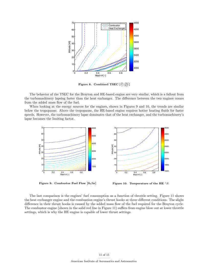
When looking at the energy sources for the engines, shown in Figures 9 and 10, the trends are similarbelow the tropopause. Above the tropopause, the HE-based engine requires hotter heating fluids for fasterspeeds. However, the turbomachinery lapse dominates that of the heat exchanger, and the turbomachinery’slapse becomes the limiting factor.
Mach # [−]
Altitu
de
[kft
]
0 0.2 0.4 0.6 0.80
10
20
30
40
50
60
70
1000
2000
3000
4000
5000
6000
Figure 9. Combustor Fuel Flow [lb/hr]
Mach # [−]
Altitu
de
[kft
]
0 0.2 0.4 0.6 0.80
10
20
30
40
50
60
70
1600
1800
2000
2200
2400
2600
2800
3000
Figure 10. Temperature of the HE ◦R
The last comparison is the engines’ fuel consumption as a function of throttle setting. Figure 11 showsthe heat exchanger engine and the combustion engine’s thrust hooks at three different conditions. The slightdifference in their thrust hooks is caused by the added mass flow of the fuel required for the Brayton cycle.The combustor engine (shown in the solid red line in Figure 11) suffers from engine blow out at lower throttlesettings, which is why the HE engine is capable of lower thrust settings.
11 of 15
American Institute of Aeronautics and Astronautics

0 500 1000 1500 2000 2500 3000 35002
4
6
8
10
12
14
16
Thrust [lbf]
Thrust
SpecificEnergy
Consumption[kft∗l
bf
s∗l
bf]
Combustor Sea Level Static M = 0, h = 0 ftCombustor Slow Cruise M = 0.5, h = 40000 ftCombustor Fast Cruise M = 0.7, h = 40000 ft
HE Sea Level Static M = 0, h = 0 ft
HE Slow Cruise M = 0.5, h = 40000 ft
HE Fast Cruise M = 0.7, h = 40000 ft
Figure 11. Thrust Hook of HE-Based Engine
The above heat exchanger engine was designed at sea level static with 3,500 lb of thrust. Alternatively,an engine could have been flat-rated to meet the thrust requirement at cruise. For comparison, an enginedesigned for the cruise operating conditions and an engine designed for sea level static were both constrainedto provide 3,500 lb of thrust at Mach 0.7 at 45,000 ft. This condition (Mach 0.7 at 45,000 ft) will becalled the reference point. The same on-design engine conditions in Table 1 are applied to these designs attheir respective design points, including reaching maximum wall temperature and maximum turbine inlettemperature at the design point. This implies that the heat exchanger surface area and the turbomachinerysizes are scaled to meet the on-design engine conditions. For simplicity, the engine designed with a designpoint of M = 0.7 at 45,000 ft is referred to as the “Cruise Engine,” and the engine designed at M = 0 at 0ft(sea level static) is referred to as the “Comparable Engine.” For these graphs, the engines were throttledback until they were within all of the limits. Therefore these graphs are for maximum available throttle.
3890
12800
21700
30600
3950048300
57200
66100
Altitu
de
[kft
]
Mach # [−]
0 0.1 0.2 0.3 0.4 0.5 0.6 0.7 0.80
10
20
30
40
50
60
70Reference point
Comparable Engine
3890
12800
21700
30600
39500
Altitu
de
[kft
]
Mach # [−]
0 0.1 0.2 0.3 0.4 0.5 0.6 0.7 0.80
10
20
30
40
50
60
70Reference point
Cruise Engine
Figure 12. Energy Required [ kft−lbflbm
]
The specific energy required from each engine sets the performance requirements on the LENR energysource. Conservative performance requirements were preferred due to the lack of knowledge of the LENRperformance. Figure 12 displays the specific energy requirement of both the engines. At operating condi-tions higher in altitude and slower in speed than the reference point, the specific energy requirements areapproximately the same for both engines. At operating conditions lower in altitude and faster in speed,the turbomachinery requires higher wall and turbine inlet temperatures, so the cruise design engine hasto reduce throttle. Consequently, the cruise design engine demands less energy for its maximum availablethrottle while operating below the reference point, but it will provide less thrust as will be shown in Figure13. This results in the cruise design engine requiring half the LENR maximum power and throttle-ability as
12 of 15
American Institute of Aeronautics and Astronautics

that required by the comparable engine, producing a more efficient system.The viability of the cruise design engine depends on whether it can provide enough thrust at takeoff.
Figure 13 compares the two engines’ thrust. Again, at operating conditions higher in altitude and slowerin speed than the reference point, the behavior is roughly the same for both engines. However, the cruisedesign engine has a maximum available thrust of 10,800 lb at sea level static, while the comparable enginehas a maximum available thrust of 23,100 lb at sea level static. These engines may be oversized for theapplication of a extremely-long-endurance ISR mission, but the general trend shows the cruise design engineuses half of the fuel of the comparable engine, while requiring less heat exchanger area and weight.
1500
3500
5500
7500
9500
11500
1350015500
175001950021500
Mach # [−]
Altitu
de
[kft
]
0 0.1 0.2 0.3 0.4 0.5 0.6 0.7 0.80
10
20
30
40
50
60
70Reference point
Comparable Engine
1500
3500
5500
7500
9500
Mach # [−]
Altitu
de
[kft
]
0 0.1 0.2 0.3 0.4 0.5 0.6 0.7 0.80
10
20
30
40
50
60
70Reference point
Cruise Engine
Figure 13. Thrust Required [lbf]
To better understand the performance differences of these two engines, specific excess power was derivedusing a drag polar similar to that of a General Atomic Predator B.29,30 Both engines were scaled to for 275feet per minute rate of climb at the reference point. The comparable engine has double the excess powerat sea level static, and its peaks are at higher speeds than the cruise design engine, as seen in Figure 14.Therefore, the comparable engine has better point performance, such as shorter take-off lengths and fasterclimb rates.
0
200
400
600
800
1000
1200
1400
1600
Mach # [−]
Altitude [kft]
0.2 0.3 0.4 0.5 0.6 0.7 0.8 0.90
10
20
30
40
50
60
70
Reference point
Comparable Engine
0
100
200
300
400
500
Mach # [−]
Altitu
de
[kft
]
0.2 0.3 0.4 0.5 0.6 0.7 0.8 0.90
10
20
30
40
50
60
70
Reference point
Cruise Engine
Figure 14. Excess Power [ ftmin
]
Table 5 demonstrates the physical size differences of the two engines. By having the engine designed atcruise, the fan areas are drastically reduced, which results in a decrease in the engine weight. As seen in Figure14, the engines have almost the same energy consumption at the reference point. However, the comparableengine has to provide almost six times the energy at sea level static, which results in the comparable enginehaving lower heat exchanger wall temperatures and lower turbine inlet temperatures. The cruise designengine has a heat exchanger surface area of roughly a third of that required by the comparable engine,
13 of 15
American Institute of Aeronautics and Astronautics

leading to a heat exchanger weighing roughly a third of the heat exchanger of the comparable engine.
Table 5. Engine Specifications
Specification Comparable Engine Cruise Engine
Compressor Face Area, A2 (ft2) 10.3 7.2
Turbine Face Area, A4 (ft2) 7.1 1.7
Exit Nozzle Area, A8 (ft2) 5.4 3.2
Hex Total Surface Area (ft2) 1580 420
Hex Total Fin Weight (lbm) 2655 706
Tw at the reference point (◦R) 1926 2700
TIT at the reference point (◦R) 1627 1970
Static Sea Level Thrust (lbf) 23100 10800
Conclusions on LENR Engine
The heat exchanger based engine seems a reasonable concept, with performance of almost the same as today’sJet-A fueled turbojets. It also opens the doors to be powered by a multitude of power sources, such as anLENR system with extremely low fuel burn. Designing the heat exchanger engine close to the cruising pointbrings benefits in efficiency, weight, and throttle-ability requirements. It does, however, have less staticthrust. For a long endurance ISR mission, powered by a future LENR system, the heat exchanger engineseems to be a promising concept.
Trend Toward Higher Weight, Higher Reliability
The nearly unlimited energy offered by an LENR system brings up questions of aircraft sizing. An aircraftpowered by LENR could be sized by point performance instead of mission performance, which is common tomost ISR missions of today. This paradigm shift means that the weight of the system will directly affect thesizing of the aircraft. A vehicle designed to stay aloft for months or years will need to be extremely reliable,and this may bring a weight penalty in the form of either stiffer and more robust structures, or parallel-redundant systems. Reliability could be approached in a similar fashion to spacecraft since the aircraft isintended to remain airborne for several years. Like a satellite, eliminating repeated takeoffs and landingswould reduce cyclic pressure loads found in a traditional aircraft, and could reduce required structuralweight. Flight controls could also be made more reliable by moving to electrical actuators, or even syntheticjet control surfaces.
IV. Conclusion
Advanced energy technologies like LENR allow aircraft designers the freedom to design without concernfor fuel weight. This freedom relieves the designer from having to maximize efficiency in order to squeezemore miles out of the aircraft’s range. However, the aircraft must now be designed for endurances notconceivable with today’s technology. Such extreme flight durations, perhaps years in length, demand a newapproach to aircraft design: one that takes the focus off of maximum efficiency and places it on energymanagement and extremely high reliability. Energy management poses its own set of problems, as futureenergy technologies such as LENR may result in closed-cycle thermodynamic cycles in which extreme heatand a need for a way to dissipate it may be an omnipresent circumstance. It is these challenges and morethat face the designers of such future aircraft.
Acknowledgments
This work has been supported by NASA Seedling Award NNX13AI17A under supervision of technicalmonitor Doug Wells. Thanks also to the rest of the LENR team at NASA Langley and Glenn researchcenters.
14 of 15
American Institute of Aeronautics and Astronautics

References
1A. Widom and L. Larsen. Ultra low momentum neutron catalyzed nuclear reactions on metallic hydride surfaces. EuropeanPhysical Journal C, 46:107–111, April 2006.
2Peter Ekstrom. Cold fusion once more becomes only hot air, May 2011.3General Electric Company. Research and Development Center. Heat Transfer and Fluid Flow Data Books: Fluid flow.
Heat Transfer and Fluid Flow Data Books. The Center, 1980.4Anonymous. Advanced stirling radioisotope generator for nasa space science and exploration missions, June 2007.5EAA. Fact sheet: 1903 wright brothers engine tests, 2013.6Fabio Penon. High temperature energy catalyzer test. Technical report, August 7th 2012.7Jonathan Fleming, Wing Ng, and Saeid Ghamaty. Thermoelectric-based power system for uav/mav applications. In
Unmanned Aerospace Vehicles, Systems, Technologies, and Operations Conference and Workshop, pages 20–23, 2002.8Jonathan Fleming, Wing Ng, and Saeid Ghamaty. Thermoelectric power generation for uav applications. In 1 st
International Energy Conversion Engineering Conference, 2003.9Inc Applied Nanotech Holdings. Nanoparticles: Nickel [ni], 2013.
10American Element. Nickel nanoparticles high purity ni nanoparticles / nanopowder, 2013.11L. V. Humble, W. W. Wachtl, and R. B. Doyle. Preliminary analysis of three ccycle for nuclear propulsion of aircraft.
(NACA RM E50H24), 1950.12I. M. Karp. Nuclear powered supercritical water cycle for aircraft propulsion. (NACA-RM-E53D29), 1952.13L. H. Fishbach, J. L. Allen, and w. C. Strack. Temperature and lifetime effects on the performance of a nuclear-powered
airplane. (NASA TM X-52432), 1968.14P. M. Finnegan, R. L. Puthoff, and J. W. Turnbow. Preliminary impact speed and angle criteria for design of a nuclear
airplane fission product containment vessel. (NASA-TM-X-2245 , E-6025), 1971.15R. L. Puthoff and C. C. Silverstein. Application of heat pipes to a nuclear aircraft propulsion system. (NASA-TM-X-52791
, PROPULSION JOINT SPECIALISTS CONF., SAN DIEGO, CA, UNITED STATES, 15-19 JUN. 1970), 1970.16F. E. Rom. Subsonic nuclear aircraft study. (NASA-TM-X-1626 , E-3914), 1968.17F. E. Rom. Airbreathing nuclear propulsion, a new look. (NASA-TM-X-67837), 1971.18Alan H Epstein et al. Millimeter scale, mems gas turbine engines. In Proceedings of ASME turbo expo, volume 2003,
2003.19Nancy A. Melville. Drones, smartphones eyed for medical aid to remote regions, October 2013.20JL Klann and CA Snyder. Nasa engine performance program. Aeropropulsion Analysis Office, NASA Lewis Research
Center, Cleveland Ohio, 1997.21USAF. F5E/F Flight Manual. United States Air Force, to 1f 5e 1 edition, August 1978.22CH Vance. Standard aircraft characteristics performance of the northrop f-5e air superiority fighter with two j85-ge-21
engines. Northrop Report NOR, pages 76–158, 1976.23Fine Tubes Ltd. Space plane skylon, 2013.24Inc. High Temp Metals. Inconel 718 technical data, 2013.25Inc Rolled Alloys. Data sheet ra333, 2009.26W.M. Kays and A.L. London. Compact heat exchangers. Krieger Pub. Co., 1984.27Joachim Kurzke. Model based gas turbine parameter corrections. In Proceedings of the ASME International Gas Turbine
And Aeroengine Congress And Exposition, 2003.28Thomas H Hobbs and Swart H Nelson. Category ii yj and j85-ge-5 engine follow-on evaluations. Technical report, DTIC
Document, 1961.29NASA. Nasa dryden fact sheet - altair/predator b, May 2008.30AFCESA CEO. Engineering technical letter (etl) 09 1 airfield planning and design criteria for unmanned aircraft systems
(uas), September 2009.
15 of 15
American Institute of Aeronautics and Astronautics