Embed Size (px)
Citation preview

Impact of Extended DRX Cycles on Battery Lifetimes and UE Reachability
VIGNESH NARASARAJU [email protected]
Academic Supervisor: Dr. Cicek Cavdar, KTH Industrial Supervisor: Dr. Emre A. Yavuz, Ericsson AB Examiner: Prof. Jens Zander, KTH TRITA-ICT-EX-2016:126


Abstract
Several UE energy consumption optimization techniques have been proposed for Machine Type Communication (MTC) devices. Extended Discontinuous Reception (eDRX) in idle mode is one such technique wherein an UE in idle mode wakes up only during its Paging Occasion (PO) to monitor paging messages from eNodeB (eNB). The PO is located within a Paging frame (PF). The PF is a function of System Frame Number (SFN) cycle of eNB. The paging messages may be sent asynchronously from multiple eNBs to a UE. Due to asynchronous operation of eNBs, SFN takes on different values at a given point in time and therefore a paging message is transmitted at different points in time from different eNBs. Due to this SFN misalignment between eNBs, an idle mode UE might receive and respond to the same paging message from different eNBs and/or miss a PO and thus the paging message. Due to this spread in time of SFN and PO, the actual handling of paging message by the UE becomes inefficient leading to increased UE energy consumption and decreased reachability. These issues, resulting from paging handling, will get amplified further if DRX period is extended longer (eDRX). In this study, we investigate the impact of eDRX cycles and mobility related parameters such as UE speed, cell size and size of SFN misalignment between eNBs on UE energy consumption, use of network resources and UE reachability. Receiving and responding to the same paging message results in increased energy consumption for UE and increased signaling between UE and the network. Missing a PO results in delayed paging reception and hence decreases UE reachability. As the DRX cycle lengths are increased from existing maximum of 2.56 seconds to 10.24 seconds and beyond, we see a reduction in UE energy consumption by more than 90%, but the network signaling and the delay to reach the UE increases linearly as a function of the DRX cycle length. We observe that the number of duplicate paging message receptions/missed POs is minuscule for DRX cycle lengths below 10.24 sec. At DRX cycle length of 10.24 seconds, UEs travelling across 500 m cell radius at speeds of 3, 50, 100 km/h the percentage of duplicate paging receptions are 0.07, 0.11, and 0.15 respectively. This duplicate paging message reception increases the UE energy consumption by 2.31, 6.15 and 12 percent of the total energy units respectively. Similarly, UE misses nearly 0.34, 0.39, and 0.405 percent of the total POs respectively. Depending on the number of consecutive PO misses, the UE reachability decreases. But by reducing the size of SFN misalignment between eNBs, we see that it’s possible to increase the reachability for UEs in eDRX. Further we have proposed solutions based on our analytical study to avoid duplicate paging message reception by UE, increase UE reachability and also reduce UE energy consumption using a windowing technique. We conclude that when a UE is configured with eDRX cycles, the tradeoff between battery lifetimes and UE reachability is based on mobility characteristics and service requirements. Keywords: LTE, MTC, Machine-Type-Communication, SFN, DRX, eDRX, Extended DRX, Idle Mode, Paging, M2M, Machine-to-Machine, IoT, Internet-of-Things
KTH ROYAL INSTITUTE OF TECHNOLOGY
I N F O R M A T IO N A N D C O M M U N I C A T I O N T E C H N O L O G Y


Acknowledgements I acknowledge the generous higher education opportunity provided by Sweden and KTH. My learning and time spent at KTH School of ICT have been one of best academic experiences so far.
I extend my sincere thanks to academic supervisor, Dr. Cicek Cavdar (KTH Radio Communications Laboratory, Sweden) and industrial supervisor Dr. Emre A. Yavuz (Ericsson AB, Sweden) for giving me the opportunity to purse this Master Thesis. The technical discussions with Dr. Emre on LTE paging and SFN (System Frame Number) handling were the best. I sincerely thank Dr. Cicek for guidance on energy efficiency in mobile networks and her persistent advice on academic reporting. Together, their continuous support and guidance throughout the thesis work has given me a deep insight in the area of energy efficiency in cellular networks, scientific research and 3GPP standards. Also, special thanks to Prof. Jens Zander for his constructive comments during the problem formulation phase of this work.
Finally, I am ever grateful to my parents and siblings, who encouraged me for pursuing higher education. Despite many hardships, they stood by and encouraged me all the way through. Lastly, but not the least, special thanks to friends and colleagues at Ericsson AB, Kista, Sweden, whose endless support all along the studies and work kept me on my toes to complete this education.
Vignesh Narasaraju Stockholm, Sweden, 2016

1
2
List of Acronyms
3G 3rd Generation
3GPP Third Generation Partnership Project
4G 4rd Generation
AGC Automatic Gain Control
BCCH Broadcast Control Channel
BCH Broadcast Channel
CCCH Common Control Channel
CMAS Commercial Mobile Alert Service
C-RNTI Cell RNTI
CS Circuit Switched
CSG Closed Subscriber Group
DCCH Dedicated Control Channel
DCI Downlink Control Information
DL Down Link
DL-SCH Downlink Shared Channel
DRX Discontinuous Reception
DTCH Dedicated Traffic Channel
DTX Discontinuous Transmission
EAB Extended Access Barring
ECM EPS Connection Management
eDRX Extended Discontinuous Reception
EMM EPS Mobility Management
eNB evolved Node B
EPS Evolved Packet System
ETWS Earthquake and Tsunami Warning System
E-UTRAN Evolved Universal Terrestrial Radio Access Network
FDD Frequency Division Duplex
GSM Global System for Mobile communications
H2H Human 2 Human
ID Identifier
IMSI International Mobile Subscriber Identity
IoE Internet of Everything
IoT Internet of Things
IP Internet Protocol
ISD Inter Site Distance
KHz Kilo Hertz
LCD Liquid Crystal Display
LTE Long Term Evolution

3
M2M Machine 2 Machine
MAC Medium Access Control
MCCH Multicast Control Channel
MCH Multicast channel
MHz Mega Hertz
MME Mobile Management Entity
MP Modification Period
ms Millisecond
MTC Machine Type Communication
MTCH Multicast Traffic Channel
NAS Non-Access Stratum
OFDMA Orthogonal Frequency Division Multiple Access
PA Power Amplifier
PBCH Physical Broadcast Channel
PCCH Paging Control Channel
PCH Paging Channel
PDCCH Physical Downlink Control Channel
PDCP Packet Data Convergence Protocol
PDSCH Physical Downlink Shared Channel
PF Paging Fame
PHY Physical layers
PLL Phase Locked Loop
PMCH Physical Multicast Channel
PO Paging Occasion
PRACH Physical Random Access Channel
P-RNTI Paging RNTI
PS Packet Switched
PTW Paging Transmission Window
PUSCH Physical Uplink Shared Channel
QoS Quality of Service
RACH Random Access Channel
RF Radio Frequency
RLC Radio Link Control
RNTI Radio Network Temporary Identity
RX Reception
RRC Radio Resource Control
S1AP S1 Application Protocol
SAE System Architecture Evolution
SC-FDMA Single-Carrier Frequency Division Multiple Access
SF Sub Frame

4
SFN System Frame Number
S-GW Serving Gateway
SI System Information
S-TMSI SAE Temporary Mobile Station Identifier
TA Tracking Area
TAI Tracking Area Identity
TDD Time Division Duplex
TTI Transmission Timing Interval
TX Transmission
UE User Equipment
UL Up Link
UL-SCH Uplink Shared channel
WCDMA Wideband Code Division Multiple Access

5
6
List of Figures Figure 1.1: MME sending paging request to eNBs in TA ................................. 4 Figure 1.2: UE receiving duplicate paging message from eNBs due to SFN misalignment ...................................................................................................... 5 Figure 1.3: UE missing its PO from eNB due to SFN misalignment ............... 6 Figure 2.1: DTX and DRX opportunity for UE in LTE ................................... 11 Figure 2.2: LTE type-1 frame structure .......................................................... 13 Figure 2.3: LTE DRX cycle .............................................................................. 14 Figure 2.4: LTE DRX cycle flow chart ............................................................ 16 Figure 2.5: LTE DRX cycle transitions ........................................................... 17 Figure 2.6: UE RRC_CONNECTED and RRC_IDLE mode transition ......... 19 Figure 2.7: UE DRX in connected mode ........................................................ 20 Figure 3.1: Cells and TA grouping .................................................................. 22 Figure 3.2: SFN cycle ..................................................................................... 23 Figure 3.3: LTE network elements involved in paging procedure .................. 23 Figure 3.4: LTE protocol and channels interface ........................................... 25 Figure 3.5: LTE channels involved in paging procedure ................................ 26 Figure 3.6: Paging procedure sequence diagram ........................................... 27 Figure 4.1: Cell layout and UE distribution ................................................... 31 Figure 4.2: Idle mode UE activity and energy consumption ........................ 34 Figure 4.3: Illustration of duplicated paging message reception ................. 36 Figure 4.4: Illustration of delayed paging reception due to missed PO ....... 36 Figure 4.5: Illustration of network delay, UE PO occurrence and SFN misalignment .................................................................................................... 40 Figure 5.1: Number of duplicate paging message receptions at 500 m cell radius ................................................................................................................ 43 Figure 5.2: Number of missed POs at 500 m cell radius .............................. 43 Figure 5.3: Total number of paging messages and the percentage of duplicate paging message reception by UEs at 500 m cell radius ................................... 44 Figure 5.4: UE total energy consumption and percentage of energy consumption due to duplicate paging message reception at 500 m cell radius ........................................................................................................................... 45 Figure 5.5: Total number of POs and the percentage of missed POs by UEs at 500 m cell radius .......................................................................................... 47 Figure 5.6: Average delay for the network to reach the UEs at SFN offset of 0 to 1023 between cells and 500 m cell radius .................................................... 48 Figure 5.7: Paging delay due to missed PO at DRX 2.56 sec and 500 m cell radius ................................................................................................................ 49 Figure 5.8: Paging delay due to missed POs at DRX 10.24 sec and 500 m cell radius ................................................................................................................ 50 Figure 5.9: Paging delay due to missed POs at DRX 163.84 sec and 500 m cell radius ................................................................................................................ 50 Figure 5.10: Average energy consumption versus average paging delay due to missed POs by UEs at 100 km/h speed and 500 m cell radius ......................... 51 Figure 6.1: Illustration of PTW within eDRX cycle ........................................ 53 Figure 6.2: Illustration of UE reachability without PTW technique ............... 54 Figure 6.3: Illustration of UE reachability with PTW technique .................... 55

7
Figure 6.4: Comparison of network delay to reach the UE using no-PTW and PTW technique. eDRX=10.24 sec, PTW = 10.24 sec. ...................................... 56 Figure 6.5: Ideal DRX cycle ........................................................................... 57 Figure 6.6: Non-ideal DRX cycle ................................................................... 58 Figure 6.7: Short wake-ups and ON period overlaps .................................... 59 Figure 6.8: Energy comparison for short wake-up POs ................................ 60 Figure A.1: Number of duplicate paging message receptions at 1000 m cell radius ................................................................................................................ 69 Figure A.2: Number of duplicate paging message receptions at 1500 m cell radius ................................................................................................................ 69 Figure A.3: Number of missed POs at 1000 m cell radius .............................. 70 Figure A.4: Number of missed POs at 1500 m cell radius .............................. 70 Figure A.5: Messaging exchanges due answering the duplicate paging messages between UE and eNB ......................................................................... 71 Figure A.6: Number of consecutive PO misses when UE at 3 km/h speed and 500 m cell radius ............................................................................................... 71 Figure A.7: Number of consecutive PO misses when UE at 50 km/h speed and 500 m cell radius .............................................................................................. 72 Figure A.8: Number of consecutive PO misses when UE at 100 km/h speed and 500 m cell radius ....................................................................................... 72 Figure A.9: Average delay for the network to reach the UEs at SFN offset of 0 to 511 between cells and 500 m cell radius....................................................... 73 Figure A.10: Average delay for the network to reach the UEs at SFN offset of 0 to 255 between cells and 500 m cell radius ...................................................... 73

8
List of Tables
Table 2.1: LTE Short-DRX cycle length values ................................................ 18 Table 3.1: Contents in S1AP paging message .................................................. 28 Table 3.2: Contents of RRC paging message ................................................... 29 Table 4.1: Simulation parameters ................................................................... 32 Table 4.2: DRX parameters ............................................................................. 33 Table 4.3: Sub-frame pattern for FDD ............................................................ 33 Table 4.4: Sub-frame pattern for TDD ............................................................ 33 Table 4.5: UE energy model parameters ......................................................... 35 Table 4.6: UE energy consumption parameters .............................................. 37

9

10
Table of Contents
1 Introduction ................................................................................................................. 1 1.1 Background and Motivation ...................................................................................... 2 1.2 Thesis Outline ................................................................................................................. 3 1.3 Synchronization of SFN and Paging Message Delivery .................................... 3
1.3.1 Scenario 1: UE Receiving and Responding to the Duplicate Paging Message 5 1.3.2 Scenario 2: UE Missing its PO and Receiving Delayed Paging Message ........... 5
1.4 Previous Studies in the Related Field .................................................................... 7 1.5 Thesis Objective and Research Questions ............................................................ 8
1.5.1 Thesis Objective ...................................................................................................................... 8 1.5.2 Research Questions ............................................................................................................... 8 1.5.3 Methodology ............................................................................................................................. 9
2 Energy Saving in LTE .............................................................................................. 11 2.1 Energy Saving by DTX and DRX .............................................................................. 11
2.1.1 Discontinuous Transmission – DTX ..............................................................................13 2.1.2 Discontinuous Reception– DRX ......................................................................................14
2.2 DRX Cycle ........................................................................................................................ 14 2.3 DRX in different UE Modes ....................................................................................... 18
2.3.1 DRX in Connected Mode ....................................................................................................19 2.3.2 DRX in Idle Mode ..................................................................................................................20
3 Paging Mechanism in LTE .................................................................................... 22 3.1 LTE Network Elements in Paging Mechanism ................................................... 23 3.2 LTE Channels Involved in Paging Procedure ..................................................... 24 3.3 LTE Idle Mode Paging Procedure ........................................................................... 26
4 System Setup and Performance Measures ..................................................... 31 4.1 Simulation Setup .......................................................................................................... 31 4.2 UE Energy Model .......................................................................................................... 34 4.3 Performance Metrics .................................................................................................. 36
4.3.1 UE Energy Consumption ...................................................................................................37 4.3.2 Paging Load at the eNB ......................................................................................................38 4.3.3 UE Reachability .....................................................................................................................38
5 Simulation Results and Discussions ................................................................. 42 5.1 Effect of UE mobility, cell size, SFN misalignment and eDRX cycle on paging message reception ...................................................................................................... 42 5.2 Paging Load at eNB and UE Energy Consumption ............................................ 44 5.3 UE Reachability ............................................................................................................ 47
6 Analysis of Potential Solutions for UE Energy and Reachability issues52 6.1 Preventing UE from receiving duplicate paging messages .......................... 52 6.2 Increase UE Reachability .......................................................................................... 52
7 Conclusion and Future Work .............................................................................. 62 7.1 Conclusion ...................................................................................................................... 62 7.2 Future Work .................................................................................................................. 63
References .......................................................................................................................... 66
Appendix A ......................................................................................................................... 69

11

1
1 Introduction
In cellular technologies such as 3G and 4G, energy efficiency has become one of the important goals [1]. This goal is mainly driven by the telecom service providers to reduce carbon emissions and decrease total energy consumption in the network. It is estimated that by using modern mobile cellular technology such as LTE, network operators can reduce the overall energy consumption by 60% by 2020 [2]. Energy efficient techniques are applied to both mobile networks and users respectively. In the mobile network domain, despite increase in network infrastructure and deployment, network operators strive to reduce their annual energy bills by using the network equipment efficiently, adapting to traffic flow in the network.[3]. In the mobile user domain, energy efficiency is focused on reducing both the UE energy consumption and unnecessary use of radio network resources. Compared to mobile network domain, energy efficiency or reducing energy consumption in mobile user domain/UE is crucial due to the fact that source of energy is limited via size of battery in the UE. Therefore, reducing the UE energy consumption is one of the main challenges being posed to cellular technology standard bodies due to the advent of energy hungry smart communicating devices. The smart UEs are used for both H2H and M2M communication. In H2H communication, the UE is used for communication between human users. In M2M communication [4], UE takes the role of machine (e.g. MTC) that acts as a user and has the ability to communicate with other UEs including human users. Some of the M2M communication services include transportation (e.g. automotive, asset tracking, parking meters), healthcare (e.g. wearable sensors, monitoring devices), and utilities industries (e.g. smart grid for electricity, water and gas). In the smart UE, the main energy consuming parts were analyzed in [5]. For example, wireless modules, LCD, touch screen panel, backlight and maintaining a connection to the network: all these tasks consume significant amount of energy. It is suggested that significant energy savings can be achieved by turning off energy source to unused device components in the UE [5] during no-traffic time instants via DRX mechanism. Even though one could argue for having an efficient and high energy capacity battery for the UE, the pace of development of smart UE and energy hungry applications has outpaced the slow development of compact sized UE batteries. As a result, the focus has shifted towards saving UE battery energy [6]. Also, since the energy storage is limited by the size of UE battery and available technology to date, efforts are made to reduce the overall UE energy consumption and yet keep the UE operational for longer duration and make it available for use to the user. Energy saving is also necessary for smart UEs in critical communication fields where energy supplies are discontinuous or recharging/changing batteries often is also a challenge [7]. In general, LTE offers energy saving mechanisms via DTX and DRX for network and UE respectively. eDRX functionality is specified by 3GPP via Release-13. In this

2
thesis work, we analyze the impact of eDRX/longer DRX cycles on energy consumption and reachability for idle mode UEs.
1.1 Background and Motivation
Reducing energy consumption for MTC devices, referred as UE in rest of this literature, is extremely important as this helps them to be operational for longer periods (e.g. weeks, months or even years) without any interruption for maintenance. Reducing UE energy consumption also increases system capacity, i.e. by minimizing unnecessary signaling towards the network when the UE is in low energy consumption or sleep mode via DRX. Depending on the configuration from network for different traffic situation and required QoS, the length of DRX can vary from small, long to very long periods respectively. Among many other energy consumption optimization techniques for UE, proposed by 3GPP [8] in LTE, eDRX in idle mode is one such technique where an idle mode UE turns off its receiver circuitry over longer periods of time to save battery energy.
An idle mode UE is reachable to the network/eNB only via paging request within DRX/eDRX cycle. The paging requests are sent by MME to all the eNBs in the UE registered TA. The eNBs further delivers paging messages asynchronously at defined time instants called PO, which repeats every DRX cycle. The PF, which contains the PO, is a function of SFN cycle on the air interface, i.e., the PF is one among the many radio frames which are numbered and delivered in a cyclic manner (SFN cycle) by the eNB. However, SFN cycle in each eNB could start at a different point in time. As a result, the paging message handling by the UE becomes inefficient, leading to increased UE energy consumption and reduced UE reachability, which is explained further in section 1.3. Among all the signaling traffic generated by MME, it is estimated that the signaling due to paging alone contributes to around 29% of the total signaling load in the network [9]. Therefore, one cannot ignore the inefficient handling of paging messages by UE and rest of the network elements, which could further lead to increased UE energy consumption, signaling load and reduced UE reachability under eDRX technique. The inefficient handling of paging messages intensifies as the DRX cycles are extended longer (eDRX). Therefore, it is important to analyze the impact of eDRX cycles on UE energy consumption and reachability due to the paging mechanism.

3
1.2 Thesis Outline
The structure of this thesis report is organized as follows: In section 1.3 we introduce the problem being addressed, as it forms the motivation for our work. Section 1.4 discusses the previous work in the related field and mentions the research gap and section 1.5 lists our objectives and research questions answered in our work and also the methodology followed in this work. Chapter 2 and 3 contains our literature survey highlighting our theoretical understanding of the subject. In chapter 4 we discuss the system simulation model, assumptions, energy model and performance metrics used in our analysis. Chapter 5 contains simulation results, performance analysis, discussions and an analytical study on potential solutions to the problems. Finally, chapter 6 contains conclusions and scope of improvement for future work.
1.3 Synchronization of SFN and Paging Message Delivery
Our motivation to say that “ eDRX could lead to increased UE energy consumption, signaling load and reduced UE reachability due to inefficient paging handling” is arrived by analyzing the problem causing scenarios explained further via a simple illustration. This is also the basis for our analysis work in this thesis. Let cells cell-1, cell-2 and cell-3 belong to the same TA and are managed by an MME. Since an idle mode UE is registered and known to the network only at granularity of TA, MME sends paging request to the eNBs in cells cell-1, cell-2 and cell-3, as shown in Figure 1.1. The UE in idle mode wakes up once every DRX cycle at a specified time instant, PO, to check for a possible paging message. The PO is located within the PF in the SFN cycle of eNB. However, the SFN cycles among eNBs are not synchronized. For example, at time t = 0 (zero), the SFN may take on different values in each cell. As a result, the paging message at a particular PO for a UE is not sent at same time instant from all the eNBs. But the idle UE wakes up when the time for its PO arrives. If the UE is mobile and wakes up during its PO in another cell, it may miss its PO in the new cell due to SFN misalignment between the eNBs. That is, the paging message from the eNB in the new cell might have been already sent from eNB or is yet to be sent from eNB. Further, due to eDRX, where the cycle lengths can be in the range of minutes, hours or even longer, the occurrence of a PF and hence PO for a UE also increases with time. As a result, the handling of paging message by an idle mode UE that is moving across cells will have negative impact on its energy consumption, reachability and signaling load on the network.

4
MME
Cell-2
Cell-3Cell-1
@t = 0SFN = 0
@t = 0SFN = 512
@t = 0SFN = 1023
Figure 1.1: MME sending paging request to eNBs in TA We identify two problems causing scenarios in paging handling due to SFN misalignment and eDRX. The scenarios are described further on:
5
1.3.1 Scenario 1: UE Receiving and Responding to the Duplicate Paging Message
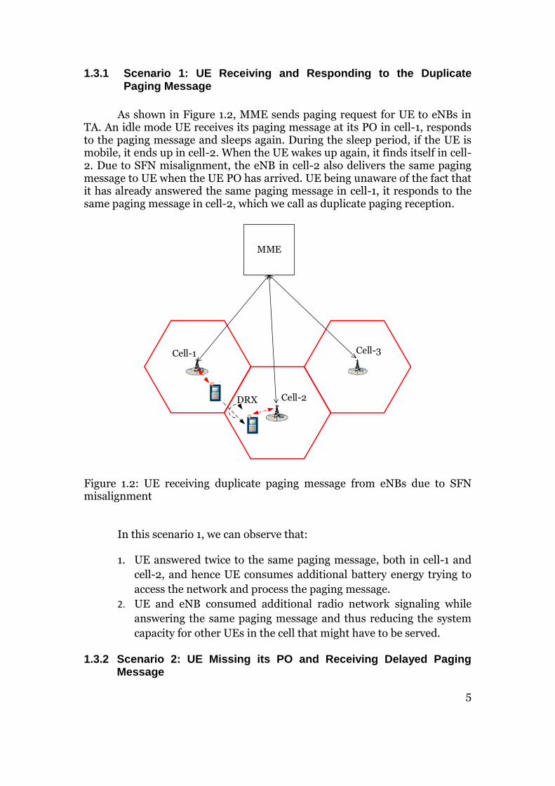
As shown in Figure 1.2, MME sends paging request for UE to eNBs in TA. An idle mode UE receives its paging message at its PO in cell-1, responds to the paging message and sleeps again. During the sleep period, if the UE is mobile, it ends up in cell-2. When the UE wakes up again, it finds itself in cell-2. Due to SFN misalignment, the eNB in cell-2 also delivers the same paging message to UE when the UE PO has arrived. UE being unaware of the fact that it has already answered the same paging message in cell-1, it responds to the same paging message in cell-2, which we call as duplicate paging reception.
MME
Cell-2
Cell-3Cell-1
DRX
Figure 1.2: UE receiving duplicate paging message from eNBs due to SFN misalignment
In this scenario 1, we can observe that:
1. UE answered twice to the same paging message, both in cell-1 and
cell-2, and hence UE consumes additional battery energy trying to
access the network and process the paging message.
2. UE and eNB consumed additional radio network signaling while
answering the same paging message and thus reducing the system
capacity for other UEs in the cell that might have to be served.
1.3.2 Scenario 2: UE Missing its PO and Receiving Delayed Paging Message

6
As shown in Figure 1.3, MME sends paging request for UE to eNBs in TA. An idle mode UE receives its paging message at its PO in cell-1, responds to the paging message and sleeps again. During this sleep period, MME sends a new paging with new information to the UE. When the UE is awake it finds itself in cell-2. But due to SFN misalignment, the PF and PO carrying the paging message for the UE has not yet arrived or could have already passed in cell-2. As a result, UE goes back to sleep mode to wake up at its next PO. If the idle UE moves into cell-3 during this sleep time, UE may again miss its PO again due to SFN misalignment or receive a paging message at its PO. If the idle UE is moving at a high speed such that it crosses many cells and wakes up once during eDRX cycle in each cell, the possibility of UE missing its PO due to SFN misalignment will be high resulting in more time for the network to reach the UE.
MME
Cell-2
Cell-3
DRX
Cell-1
DRX
Figure 1.3: UE missing its PO from eNB due to SFN misalignment
In this scenario 2, we can observe that:
1. UE receives a delayed paging message or might even miss the PO
and paging message containing time critical information, such as SI
updates and warnings.
2. Missing a paging message causes increased delay for the network to
reach the concerned UE.

7
1.4 Previous Studies in the Related Field
Several studies have been carried out w.r.t eDRX cycles, focusing mainly on reducing UE energy consumption or increasing UE energy efficiency. In some studies the authors also mention the effects of eDRX cycles on paging handling. For example, they analyze the effects such as delayed SI acquisition, delayed cell reselection and also UE being paged in a different TA while moving across cells when in idle mode. eDRX cycle is also referred as extended paging cycle in some literature. A study on extended paging cycles for M2M devices was done in [10]. The authors evaluate the best possible ways to reduce M2M device energy consumption for different traffic scenarios. Extending the paging DRX cycles beyond the current limit of 2.56 sec with shorter RRC inactivity timers reduces UE energy consumption for infrequent M2M traffic but increases the packet buffering delay in the network. Authors in [11] developed an energy model and analyzed the impact of eDRX cycles on M2M devices that are mobile. Their results suggest that both the energy consumption and device battery lifetime can be improved, whilst the device responsiveness to network reach is compromised. A study on extended paging cycles for MTC UEs and its effect on unnecessary SI acquisition was done in [12]. In order to eliminate UEs missing the updated SI when eDRX cycles are larger than the MP, the authors proposed a solution with two different MP based SI acquisition via normal MP and extended MP. This two different MP based SI acquisition differentiates between MTC (extended paging cycle and extended MP) and non-MTC (default paging cycle and normal MP) UEs. In [13] the authors discuss the energy saving due to eDRX cycle and issues related to mobility of MTC UEs in idle mode. The issues discussed are delayed cell reselection due to longer DRX cycle (causing the UE to be paged in the wrong TA), delayed SI change notification if the DRX cycles are longer than the MP and possibility of SFN bit extension for supporting longer DRX cycle lengths. In order to overcome delayed cell reselection and SI change notification issue, the authors propose a solution via early cell-reselection and SI reading just before the UE active time within the eDRX cycle. But none of the above mentioned studies discuss the effect that SFN misalignment and eDRX cycles have on paging handling for an idle mode UE and its ultimate impact on UE energy consumption and reachability. We try to address this research gap in this thesis.

8
1.5 Thesis Objective and Research Questions
Noting our observations from scenarios 1 and 2, described in section 1.3, we aim to analyze the role of different mobility related parameters in paging handling during eDRX cycle for idle mode UEs. This will pave the way forward to design smart solutions to reduce UE energy consumption, signaling load and increase reachability during eDRX. Our thesis objective and resulting research questions are as follows:
1.5.1 Thesis Objective
Based on the research gap identified in the previous studies in related field and the problem scenarios, we aim to evaluate the impact of eDRX cycles on idle mode UEs with the following objectives:
Evaluate the impact of network deployment parameters on UE energy
consumption and reachability for UEs configured with eDRX cycles.
Avoid redundant signaling for call establishment due to receiving
duplicate paging messages or delay for the network to reach the UE
due to missing POs.
1.5.2 Research Questions
In order to achieve the objectives mentioned above, we address the following research questions:
What is the impact of parameters, such as UE speed, cell size and SFN
misalignment between eNBs on UEs configured with eDRX cycles?
How does eDRX configuration impact the trade-off between UE energy
consumption and its reachability?
How can we reduce redundant signaling and energy consumption in
UEs due to duplicate paging message receptions or delay for network to
reach UEs configured with eDRX?
9
1.5.3 Methodology
In this Thesis work, we follow a quantitative analysis method to analyze the effects of different mobility related parameters and duration of SFN misalignment between eNBs on energy consumption and reachability for eDRX configured UEs. In order to create the problem causing scenarios, explained in section 1.3.1 and 1.3.2, and observe the effect of different input parameters, we simulate the scenarios using MATLAB software application. Through simulation, we have the flexibility to repeat the experiment quickly with different sets of input parameters and collect necessary data for performance analysis. Before performing the simulation work, we do an extensive literature study. Initially, LTE network architecture, different energy efficient mechanism will be studied. Secondly, paging and DRX mechanism will be studied. Finally, we propose solutions for efficient handling of paging messages for eDRX configured UEs, with focus on reducing UE energy consumption and increasing reachability for the network.

10
11
2 Energy Saving in LTE
Before starting our analysis on the problem, we perform an extensive literature study to understand different energy saving options, paging mechanism, and different entities involved in paging mechanism in the LTE network. This literature study will help us to simulate the problem causing scenarios and capture necessary results for our analysis.
2.1 Energy Saving by DTX and DRX
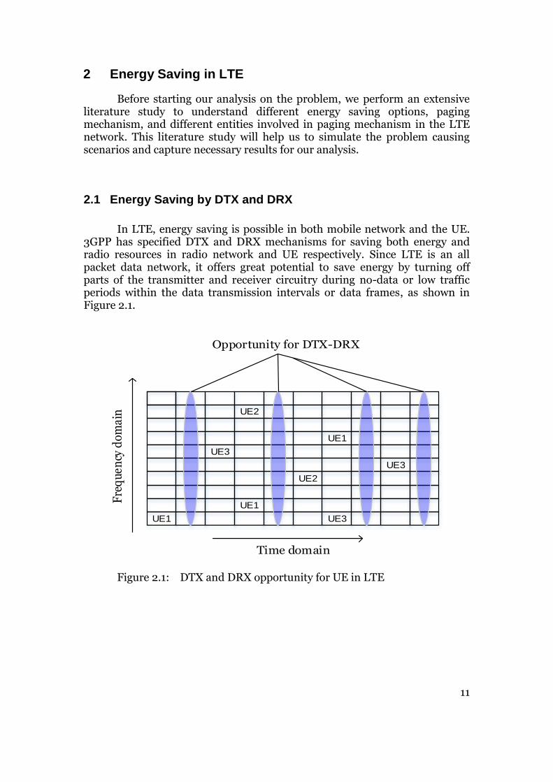
In LTE, energy saving is possible in both mobile network and the UE. 3GPP has specified DTX and DRX mechanisms for saving both energy and radio resources in radio network and UE respectively. Since LTE is an all packet data network, it offers great potential to save energy by turning off parts of the transmitter and receiver circuitry during no-data or low traffic periods within the data transmission intervals or data frames, as shown in Figure 2.1.
Time domain
Fre
qu
en
cy d
om
ain
UE1
UE1
UE2
UE2
UE3
UE3
UE1
UE3
Opportunity for DTX-DRX
Figure 2.1: DTX and DRX opportunity for UE in LTE
12
In order to visualize how DTX and DRX fit into empty transmission intervals, it is important to understand the LTE data frame structure in brief. LTE uses multicarrier technologies such as OFDMA and SC-FDMA for DL and UL transmissions respectively. LTE channel bandwidths are scalable via 1.4, 3, 5, 10, 15 and 20 MHz and can support both FDD and TDD transmission modes [14]. The frame structure for FDD is called Type 1 and for TDD it is called Type 2 [15]. We discuss only Type 1 frame structure here and the same is considered for deriving DRX PF and PO in this thesis work. For Type 2 frame structures, kindly refer [15]. The Type 1 frame structure is divided into hierarchical units as resource elements, slots, sub-frames and radio frames, smallest being the resource element and largest being the radio frame, as shown in Figure 2.2. Each radio frame is 10 ms in time duration and contains ten sub-frames, each 1 ms in time duration. Each sub-frame has two slots, each 0.5 ms time duration. A single UL or DL transmission is done at the granularity of sub-frame (1 ms), referred to as TTI. When there is no transmission, the sub-frame or contiguous of sub-frames offers opportunity for DTX or DRX, as shown in Figure 2.1. Further down, the sub-frame is divided into smaller units of frequency and time resources in a grid fashion, called as resource elements. In the frequency domain, the frequency band is divided into sub-carriers with sub-carrier spacing of 15 KHz to maintain orthogonality. The total number of sub-carriers depends on the channel bandwidth being used. For example, if the channel bandwidth is 10 MHz, then there are 600 sub-carriers in the frequency domain. In the time domain, the resources are divided into 14 OFDM symbols for normal cyclic prefix and 12 OFDM symbols for extended cyclic prefix per sub-frame. Each OFDM symbol has time spacing of 66.67 µs (1/15 KHz). An UE in the LTE network is scheduled in multiples of resource block pair, contained within one sub-frame. Each resource block pair is comprised of 12 sub-carriers (180 KHz = 12*15 KHz) and 14 OFDM symbols (assuming normal cyclic prefix).

13
Radio frame = 10 ms
Sub-frame = 1 ms
Slot 0 = 0.5 ms Slot 1 = 0.5 ms
14 OFDM symbols
12 S
ub
-car
rier
s
Resource element
Figure 2.2: LTE type-1 frame structure
2.1.1 Discontinuous Transmission – DTX
It is estimated that in a mobile cellular network: GSM, WCDMA or LTE, around 80% of the energy is consumed at the radio network side, specifically the radio unit at the base station [16]. Within radio unit, it is mainly the PA in the transmitter that consumes most of the energy during operation. In DTX, the radio transmitter is configured to switch off for a defined period of time during low or no traffic to reduce energy consumption. DTX can be applied in both DL and UL directions. When applied in downlink, it’s called cell-DTX, and when applied in uplink it’s called UE-DTX [17]. In the cell-DTX the PA in the radio unit is put to sleep mode during periods of inactivity within data transmission [16]. In the UE-DTX, the UE transmitter is put to sleep mode, mainly during a speech call as there are instants of inactivity or pauses in a speech session. This helps the UE to save battery energy and increase the energy efficiency. When no data transmission is scheduled, UE-DTX also helps to reduce considerable amount of uplink interference over-the-air and increase uplink capacity in the cell so that more number of UEs can be served [17].

14
2.1.2 Discontinuous Reception– DRX
In DRX, the UE radio receiver is switched off from listening to radio channel for a defined period of time in cycles, called as DRX cycles, during low or no traffic to reduce energy consumption. By switching off its receiver circuitry, UE saves battery energy and increases its operating life time. For example, when DRX is applied to voice calls, it can provide more talk time for the user by keeping the UE operational for longer duration, thereby increasing user satisfaction [18]. DRX also helps to save precious radio resources over-the-air in both DL and UL directions by freeing the channel resource and increase the overall system capacity [19]. However, energy saving via DRX comes at a cost such as extended delay in RX of data and delay in network re-entry for the UE [19]. DRX is configurable and can be turned ON/OFF by eNB via RRC signaling towards the UE. DRX is specified on both MAC [20] and RRC layers in the protocol stack [21].
2.2 DRX Cycle
LTE DRX cycles were specified by 3GPP in [22]. A typical DRX cycle consists of alternating periods of ON and OFF time periods with predefined duty cycles [20], as shown in Figure 2.3. A DRX cycle length in physical terms is basically the number of radio frame/sub-frame time durations that the UE sleeps for.
DRX Cycle
TON
UE shall monitor PDCCH
TOFF
TInActivity
Figure 2.3: LTE DRX cycle

15
DRX cycle is controlled by a set of timers [22]. These timers govern the ON and OFF time periods of a DRX cycle.
1. TON: Specifies the minimum time duration or the number of sub-frames that the UE is required to monitor the PDCCH every 1 ms to check if there is any resources allocated for transmission in either DL or UL.
2. TInActivity: Specifies the number of consecutive sub-frames that UE shall stay active and monitor PDCCH further, following a successful decoding of a PDCCH and presence of respective UE scheduling information, if any. This timer is started/restarted every time when the UE successfully decodes a PDCCH and if it is scheduled, indicating a new data transmission. This helps the network to keep the UE awake beyond the ON time period, TON, when the data is buffered in the network.
3. TOFF: Specifies the time period or the number of sub-frames that the UE shall sleep where it is required to turn-off its receiver circuitry.

16
A flow chart illustrating different steps in DRX cycle is as shown in Figure 2.4.
UE sleep
DRX cycle expires ?
Turn ONUE RX
Decode PDCCH
ON duration expiries ?
UE sleep
InActivity timer expires ?
Decode PDCCH
Start InActivity timerNo
Yes
YesNo
No Yes
No
No
Yes
YesUE scheduled
with data ?
UE scheduled with data ?
Figure 2.4: LTE DRX cycle flow chart Source: [23]

17
Depending on how often the UE is allowed to monitor the PDCCH, the DRX cycle lengths are divided into short-DRX and long-DRX cycle. Different DRX cycle transitions are as shown in Figure 2.5.
UE Active
Short DRX Cycle
Long DRX Cycle
UE Idle
RRC_CONNECTED
RRC_IDLE
Figure 2.5: LTE DRX cycle transitions
When the UE is in active mode, a short-DRX cycle is applied during short intermittent gaps between data transmission. Following a short DRX cycle, if there are any prolonged intermittent gaps between data transmission, a long-DRX cycle is applied. Also, depending on the configuration, it is possible for the UE to move directly from active mode to long-DRX cycle. The long-DRX cycle is a multiple of short-DRX cycle duration [21]. After the long-DRX cycle, if there is no further data transmission, then eNB commands the UE to idle mode. During either short-DRX or long DRX-cycle or idle mode, if UE receives a data packet then it switches back to active mode.

18
As per the 3GPP specification [21], the values for short-DRX cycles in number of sub-frames (sf) and corresponding time duration are shown in Table 2.1.
DRX Cycle Number of sub-frames DRX cycle length in time [ms]
Short-DRX-Cycle
sf2, sf5, sf8, sf10, sf16, sf20, sf32, sf40, sf64, sf80, sf128, sf160, sf256, sf320, sf512, sf640
2, 5, 8, 10, 16, 20, 32, 40, 64, 80, 128, 160, 256, 320, 512, 640
Table 2.1: LTE Short-DRX cycle length values DRX cycle length values and other configuration parameters are applied by the eNB depending upon the traffic situation, delay sensitiveness of different applications and service subscription by the user, e.g. QoS. Please refer [21] for more details about DRX configuration parameters and their respective values.
2.3 DRX in different UE Modes
In LTE, a UE can be in different modes [19], e.g., DETACHED or ATTACHED (RRC_CONNECTED and RRC_IDLE). Initially when the UE is powered ON, it starts in DETACHED mode where it has no information about the network and also the network is unaware of the UE. For a UE to have network access, it should be first attached to the network by initiating a random access procedure towards an eNB [17]. In simple terms, for any data transmission to happen between UE and the network, there should be a radio connection between UE and eNB. The RRC protocol offers control plane functionality for establishing and tearing down radio connections. Depending on whether there is an RRC connection or not, UE can be in either of two modes, RRC_CONNECTED or RRC_IDLE mode [21] as shown in Figure 2.6.

19
RRC_CONNECTEDRRC_IDLE
eNodeB to UE RRC connection released
UE to eNodeB RRC connection established
Figure 2.6: UE RRC_CONNECTED and RRC_IDLE mode transition
In RRC_CONNECTED mode, UE is known to both LTE core and radio network elements respectively. In this mode, the UE has a C-RNTI with a RRC connection towards specific eNB. Therefore UE is able to receive and send unicast data [21]. In RRC_IDLE mode, UE is put to sleep by eNB due to no active data transmission and therefore UE has no radio connection towards specific eNB. But the UE is still registered in the LTE core network element MME. Therefore the UE is visible to the network only at the granularity of TA and not at the eNB level [22] and hence UE can receive a paging message from all eNBs in the TA. But if the UE wishes to initiate an uplink transmission, then UE requests for a radio resource from eNB and if granted it moves to RRC_CONNECTED mode. DRX is applicable in both RRC_CONNECTED and RRC_IDLE mode.
2.3.1 DRX in Connected Mode
In connected mode, DRX is applied when a UE is active and there are inactive or idle periods during the packet arrival process: i.e., when there are no new or outstanding packets at the eNB. In this mode, the short-DRX and long-DRX cycle lengths determine how frequently the UE monitors the PDCCH for any possible downlink transmission or in other words how long the UE sleeps. An illustration of DRX for UE in connected mode is as shown in Figure 2.7.

20
ON duration
OFF duration
short DRX cycle short DRX cycle long DRX cycle continuous reception short DRX cycle
scheduled data reception
Figure 2.7: UE DRX in connected mode
In the ON duration the UE monitors the PDCCH to check for any possible scheduled transmission. And in OFF duration, the UE switches most of its receiver circuitry to save its battery energy. When in ON duration, if any transmission is scheduled, UE starts an inactivity-timer and searches for C-RNTI id on the PDCCH in every sub-frame (i.e., every 1 ms). When inactivity-timer expires, the UE may enter the OFF period within short or a long DRX cycle based on the configuration. The transition from a short to a long DRX cycle is controlled by the short DRX cycle timer. Connected mode DRX is defined in [20].
2.3.2 DRX in Idle Mode
In idle mode, DRX is applied when there is no scheduled transmission to the UE. As there is no data transmission between eNB and UE, the UE wakes up to search for P-RNTI id in PDCCH only at pre-defined instants of time, PO, to check for any possible incoming scheduled transmissions on the PCH via paging message [19] [17]. When in idle mode, the UE is configured to monitor the PDCCH for P-RNTI only at pre-defined instants of time as per DRX cycle length. In idle mode, DRX cycle is referred to as paging DRX cycle due to the fact that UE is paged for incoming notifications. The default paging DRX cycle lengths are 0.32, 0.64, 1.28 and 2.56 seconds respectively [21]. Idle mode DRX is defined in [24].

21

22
3 Paging Mechanism in LTE
Paging procedure is initiated in the core network to inform UEs in both connected and idle modes about an incoming session or event (e.g. inform UE to reattach in case of network failure, to start a CS fallback procedure for mobile terminating call, incoming PS call or message, trigger UE to acquire latest SI, deliver ETWS alerts etc.) [22]. For an idle mode UE, the core network element MME initiates the paging procedure by sending paging message to every eNB in the TA, as shown in Figure 1.1. Also, note that the each eNB can contain cells belonging to different tracking areas, but each cell can belong only to one TA, as shown in Figure 3.1 [22].
Cell-2(TAI-2)
Cell-3(TAI-1)
Cell-1(TAI-1)
Cell-4(TAI-2)
Cell-5(TAI-2)
Cell-6(TAI-3)
Cell-7(TAI-3)
Cell-8(TAI-1)
Cell-9(TAI-3)
MME
Figure 3.1: Cells and TA grouping
Paging message is delivered by eNB to UE at predefined instants of time in a cyclic manner, called as paging DRX cycle. The UE wakes up at these defined time instants to monitor and receive a paging message, if any. The time instants are called PF and PO. PF is equal to a radio frame and PO is equal to a sub-frame within the radio frame. The radio frames are numbered in sequential order from 0 (zero) to 1023 and are called SFN (10 bits). The Figure 3.2 shows a layout of single SFN cycle.

23
SFN cycle length
SFN-0 SFN-1 SFN-1023
0 1 2 3 4 5 7 8 96
Sub-Frame
0 1 2 3 4 5 7 8 96 0 1 2 3 4 5 7 8 96
Radio Frame
Figure 3.2: SFN cycle
3.1 LTE Network Elements in Paging Mechanism
A simplified LTE network model with different network elements mainly used in the paging procedure is illustrated in the Figure 3.3.
eNB
MME / S-GW MME / S-GW
eNB
eNB
E-UTRAN
EPC
Figure 3.3: LTE network elements involved in paging procedure Source: [22]

24
The LTE network elements involved in paging functionality are S-GW, MME and eNB. The interconnection between these network elements is as shown in the Figure 3.3. S-GW is responsible for terminating the interfaces towards E-UTRAN and inter-eNB handovers. MME controls and manages the mobility of the UEs in the E-UTRAN. eNB provides radio interface and connection between UE and the core network. eNB main responsibilities are radio resource control, management, measurements, scheduling and data transmission. The paging functionality is split across the network elements S-GW, MME and eNB [22]:
S-GW:
Maintains and monitors the UE context information during UE idle mode.
Buffers idle mode downlink sessions and generates paging requests for the UE.
Initiates network triggered service request procedures.
MME:
Manages TA list for UEs in idle mode.
Manages the reachability of idle mode UEs via initiation and management of paging procedures.
Manages re-transmissions of paging messages due to failure or paging response timeouts.
eNB:
Schedules and transmits paging messages originating from MME.
3.2 LTE Channels Involved in Paging Procedure
Further down the network elements, several LTE channels are involved in the paging procedure. LTE channel structure is hierarchical with different channel types: Logical, Transport and Physical. Each channel in the lower layer offers different services to upper layers via SAP between the layers, as shown in Figure 3.4 [17].

25
IP packet
PHY
MAC
RLC
PDCP
eNB
RRC
IP packet
PHY
MAC
RLC
PDCP
Transport channels
Logical channels
Radiobearers
UE
Physical channels
RRC
Figure 3.4: LTE protocol and channels interface
Logical Channels: The logical channels are used by the MAC sub layer to provide data transfer services to RLC layer. The services in these channels are characterized by what type of information is transferred [22].
Transport Channels: The transport channels are used by the physical layer to offer information transfer services to MAC and upper layers. The services in these channels are characterized by how and with what characteristics the data is transferred over the air interface [22].
Physical channels: The physical channels carry the actual information to the higher layers further on. The information in the physical channels is divided into time-frequency grid entities called as resource elements and blocks respectively [17].

26
The channels involved in the paging procedure are highlighted in Figure 3.5. Please refer [22] for more details about different LTE channels.
PCCH BCCH CCCH DCCH DTCH MCCH MTCH
PCH BCH UL-SCH DL-SCH MCH RACH
PUSCH PDSCH PMCH PRACHPDSCH PBCH
Logical
channels
Transport
channels
Physical
channels
Physical Layer
MAC Layer
PDCCH
DCIControl
Information
Figure 3.5: LTE channels involved in paging procedure
PCCH is a downlink control channel that supports transfer of paging information to all the registered UEs in the eNB area and also notifies the changes in SI.
PCH is related to PCCH. PCH is used for broadcasting the information over the eNB coverage area and supports UE DRX.
PDCCH carries the transport format and any resource allocation of the PCH.
PDSCH is used for delivering the actual user information and is used by the PCH.
3.3 LTE Idle Mode Paging Procedure
In idle mode, MME fully manages the UE mobility and the paging procedure [21]. MME paging procedure is defined in 3GPP via [25], [24], [22]. In idle mode, UE satisfies the following conditions.
UE does not have any NAS signaling connection with the core network.
No RRC connection between eNB and UE.
UE location is known to only to MME at TA granularity and not at the eNB level.
UE is registered with MME and has an EMM context in the MME.

27
The signaling flow in paging procedure is as shown in Figure 3.6.
MME
UE
(ECM Idle and RRC
Idle mode)
S1AP paging messageP-RNTI
(PDCCH)
RRC paging message
(PCCH/PCH/PDSCH)
Random access preamble
(RACH)
Random access response
(RACH)
RRC connection request
(CCCH/UL-SCH/PUSCH)
RRC connection setup
(CCCH/DL-SCH/PDSCH)
RRC connection setup complete
(DCCH/UL-SCH/PUSCH)
/
NAS service request
S1AP initial UE message /
NAS service request
Stop T3413
Paging occassion
Paging occassion
DRX cycle
DRX cycle
eNB
Start T3413
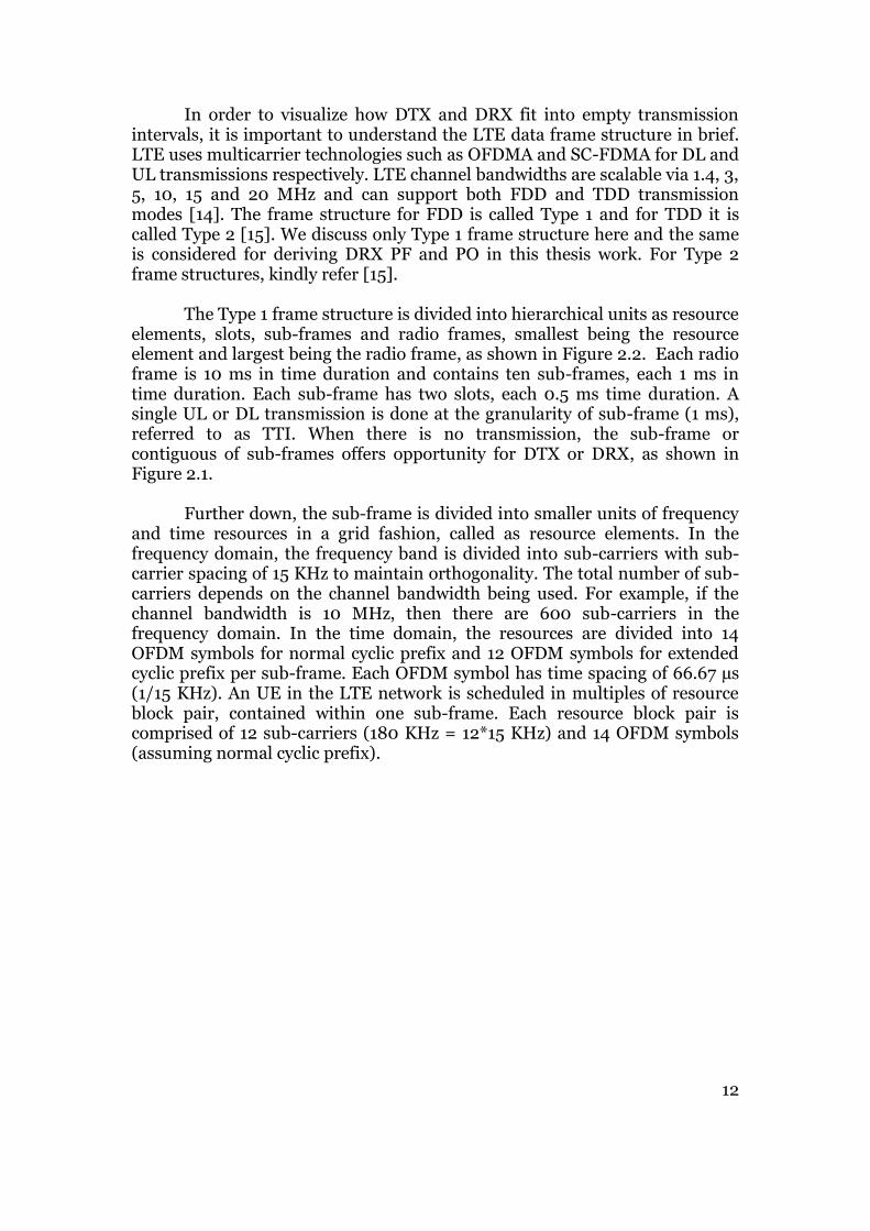
Figure 3.6: Paging procedure sequence diagram Upon receiving downlink data notification from S-GW, MME generates and forwards the S1AP paging message via backhaul links to the eNBs [21]. When MME sends the S1AP paging message for a UE, it simultaneously starts the T3413 timer. Note that the timer T3413 is used only if the incoming session is for a PS session and if the UE is addressed by S-TMSI instead of IMSI. The contents of the S1AP paging message are shown in Table 3.1 [26].
28
Information Element Value UE identity index (used at eNB to calculate PF and defined as UE_ID = IMSI mod 1024)
0 to 1023
UE paging index S-TMSI (40 bit) or IMSI (64 bit) Paging DRX 32, 64, 128, 256 Core network domain CS or PS List of TAI’s 1 to 256 instances List of CSG’s 1 to 256 instances
Table 3.1: Contents in S1AP paging message
The default paging DRX cycle length value is broadcast in SIB2. It can have values of 32, 64, 128 or 256 radio frames, which corresponds to time intervals of 320, 640, 1280 and 2560 ms respectively. The UE may be configured with a more frequent DRX cycle length by the core network. The set of allowed values are same as used in SIB2. The final chosen DRX cycle length value for the UE is the minimum of eNB and UE DRX cycle length. The DRX parameters are stored in the UE and they are updated locally whenever the DRX parameter values are changed in SI [24]. If the UE has no IMSI, e.g. when making an emergency call without USIM, then the UE_ID = 0 (zero) is used [24]. After receiving the S1AP paging message from MME, eNB constructs the RRC paging message and sends it over-the-air interface via PCCH logical channel, PCH transport channel and PDSCH physical channel. The contents of the RRC paging message are shown in Table 3.2 [21].

29
Information Element Value Paging record list Paging record
(1 to 16 instances) UE identity (S-TMSI or
IMSI)
Core network domain (PS or CS)
SI modification TRUE or FALSE
ETWS indication TRUE or FALSE Non critical extension (CMAS indication, EAB parameter modification)
TRUE or FALSE
Table 3.2: Contents of RRC paging message A single RRC paging message could contain multiple S1AP paging requests and hence can carry multiple paging records addressing multiple UEs. In idle mode, UEs wakes up at its PO every DRX cycle. During the PO, UE searches for P-RNTI within the PDCCH. If the P-RNTI has a value of FFFE, then it indicates that the respective UE might have a paging message in the PDSCH resource block. UE decodes the paging record to check for its UE identity. If the UE identity matches, then it triggers a random access procedure, else UE returns back to idle mode and again tries to find P-RNTI in PDCCH during its next PO. On a successful identity match, the UE initiates a RRC connection request and eNB responds with an RRC connection setup message. If the MME paging request was for a PS session, then the UE will include a NAS service request message in the RRC connection setup complete message and if the MME paging request was for a CS fallback session, then the UE will include an extended NAS service request message in the RRC connection setup complete message. The eNB forwards the S1AP initial UE message to the MME via backhaul links on S1 interface and MME stops the T3413 timer. Any paging response received after the T3413 timer expiry is discarded or considered expired by the MME. MME may repeat the paging request and restart the T3413 timer. After the RRC paging message decoding, if the UE (in connected and idle modes) finds SI modification element then UE searches and acquires BCCH SI. Since the paging message can also be used to inform ETWS, CMAS and EAB capable UEs (in connected and idle modes), presence of ETWS indication element triggers the UE to acquire SIB10 and/or SIB11, presence of CMAS indication element triggers the UE to acquire SIB12 and presence of EAB parameter modification indication via SIB14.

30

31
4 System Setup and Performance Measures
In this chapter we describe our simulation setup, assumptions made in the study, UE energy model, DRX parameters and its calculation, and different performance metrics considered in the problem analysis.
4.1 Simulation Setup
We create a network of hexagon cells, with an ISD = radius ∗ √3. The eNB is placed at the center of each cell. The simulations are run with a set of different UE speeds and cell radii. The UEs are distributed randomly within the network of cells, as shown in Figure 4.1. Throughout the simulation time, the UE is made to move randomly but with a specific speed. When mobile, UE takes a pause between each movement. If a UE happens to cross the network boundary, then the UE is redirected back into the network, i.e. no wrap-around, the UE returns back with a random direction. Each cell has a SFN loop count from 0 to 1023, incremented in steps of one sub-frame, but SFN loop count is started randomly among all the cells. That is, cell-1 SFN count might start at 0 (zero), while the SFN count for cell-2 might start from 100 (uniform distributed random numbers) and so on for other cells. This is done in order to simulate SFN misalignment of eNBs in the network.
Figure 4.1: Cell layout and UE distribution
32
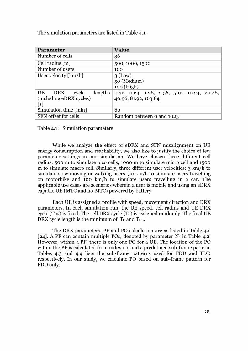
The simulation parameters are listed in Table 4.1. Parameter Value Number of cells 36
Cell radius [m] 500, 1000, 1500 Number of users 100
User velocity [km/h] 3 (Low) 50 (Medium) 100 (High)
UE DRX cycle lengths (including eDRX cycles) [s]
0.32, 0.64, 1.28, 2.56, 5.12, 10.24, 20.48, 40.96, 81.92, 163.84
Simulation time [min] 60
SFN offset for cells Random between 0 and 1023
Table 4.1: Simulation parameters While we analyze the effect of eDRX and SFN misalignment on UE energy consumption and reachability, we also like to justify the choice of few parameter settings in our simulation. We have chosen three different cell radius: 500 m to simulate pico cells, 1000 m to simulate micro cell and 1500 m to simulate macro cell. Similarly, three different user velocities: 3 km/h to simulate slow moving or walking users, 50 km/h to simulate users travelling on motorbike and 100 km/h to simulate users travelling in a car. The applicable use cases are scenarios wherein a user is mobile and using an eDRX capable UE (MTC and no-MTC) powered by battery. Each UE is assigned a profile with speed, movement direction and DRX parameters. In each simulation run, the UE speed, cell radius and UE DRX cycle (TUE) is fixed. The cell DRX cycle (TC) is assigned randomly. The final UE DRX cycle length is the minimum of TC and TUE. The DRX parameters, PF and PO calculation are as listed in Table 4.2 [24]. A PF can contain multiple POs, denoted by parameter Ns in Table 4.2. However, within a PF, there is only one PO for a UE. The location of the PO within the PF is calculated from index i_s and a predefined sub-frame pattern. Tables 4.3 and 4.4 lists the sub-frame patterns used for FDD and TDD respectively. In our study, we calculate PO based on sub-frame pattern for FDD only.

33
DRX parameter
Description Value / Formula for calculation
TUE UE DRX cycle length in radio frames 32, 64, 128, 256, 512, 1024, 2048, 4096, 8192, 16384
TC Cell DRX cycle length in radio frames 32, 64, 128, 256, 512, 1024, 2048, 4096, 8192, 16384
T UE DRX cycle length in radio frames min (TUE, TC) nB Number of POs per DXR cycle across all
UEs in the cell 4T, 2T, T, T/2, T/4, T/8, T/16, T/32
N Number of PFs within UE DRX cycle min (T, nB) Ns Number of paging sub-frames used
within a PF max (1, nB/T)
UE_ID UE identity IMSI mod 1024 PFN Paging Frame Number SFN mod T = (T/N) * (UE_ID
mod N) i_s Index pointing to PO within a PF i_s = Floor (UE_ID/N) mod Ns
Table 4.2: DRX parameters
Ns PO if i_s = 0 PO if i_s = 1 PO if i_s = 2 PO if i_s = 3
1 9 N/A N/A N/A 2 4 9 N/A N/A 4 0 4 5 9
Table 4.3: Sub-frame pattern for FDD
Ns PO if i_s = 0 PO if i_s = 1 PO if i_s = 2 PO if i_s = 3
1 0 N/A N/A N/A 2 0 5 N/A N/A 4 0 1 5 6
Table 4.4: Sub-frame pattern for TDD
34
We have made following assumptions in our study:
The antenna of eNB in each cell is omnidirectional in the horizontal plane so that DL and UL transmissions happen in all directions of the cell.
The radio channel is robust, i.e. the radio signal has no path loss.
A paging message is transmitted for each UE in every paging cycle.
4.2 UE Energy Model
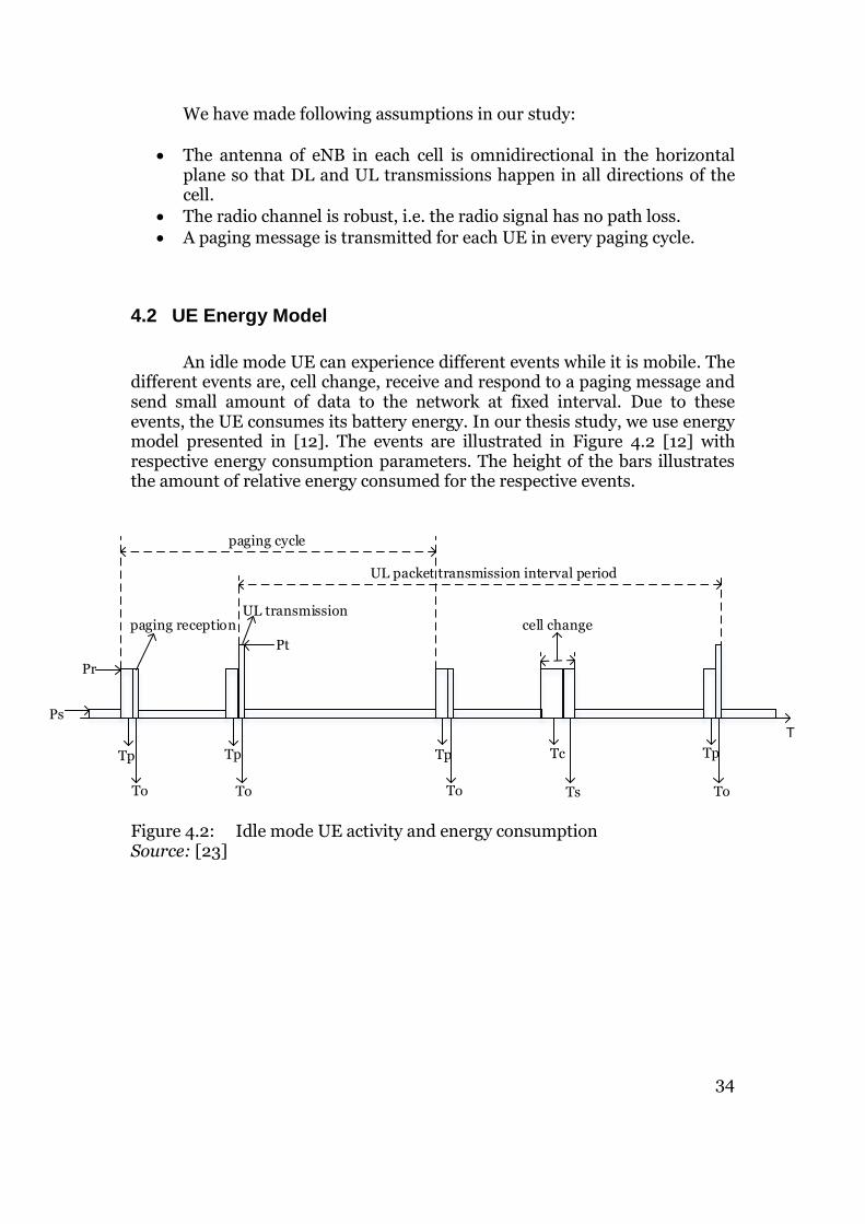
An idle mode UE can experience different events while it is mobile. The different events are, cell change, receive and respond to a paging message and send small amount of data to the network at fixed interval. Due to these events, the UE consumes its battery energy. In our thesis study, we use energy model presented in [12]. The events are illustrated in Figure 4.2 [12] with respective energy consumption parameters. The height of the bars illustrates the amount of relative energy consumed for the respective events.
T
Ps
Tp
To
Tc
Ts
Pr
Pt
TpTp
ToToTo
Tp
paging receptionUL transmission
cell change
paging cycle
UL packet transmission interval period
Figure 4.2: Idle mode UE activity and energy consumption Source: [23]

35
The energy model parameters and its values are listed in Table 4.5.
Parameter Input /
Output Description Value
Ps Input Energy consumed during sleep mode 0.01 unit/ms Pr Input Energy consumed for reception 1 unit/ms Pt Input Energy consumed for transmission 4 unit/ms Tp Input Time required for UE warm-up, cell
search and synchronization 34 ms
To Input Time required for UE to transmit data and paging reception
1 ms
Tc Input Time required for cell detection 600 ms Ts Input Time required for system information
acquisition during cell change 200 ms
T Input Total simulation duration 60 min
Table 4.5: UE energy model parameters Before receiving a paging message, UE has to initialize its receiver and synchronize with the eNB for time period Tp and receive paging during time period To. During this event the UE consumes energy Pr. While the UE is mobile, it can move to another cell. As a result, cell change procedure and new SI acquisition is performed. In the cell change activity, UE consumes energy Pr during cell detection period Tc and SI acquisition period Ts. At regular intervals the UE transmits small amount of data to the network within the period To. Due to this UL transmission, the UE consumes energy Pt. In Figure 4.3, we illustrate a UE that receives the same paging message multiple times/duplicate paging message. The UE receives its paging message at its PO in cell-1 and goes back to sleep. During this sleep period UE moves to cell-2 and wakes up at its next PO and receives a paging message in cell-2. But due to SFN misalignment between cell-1 and cell-2, the eNB in cell-2 delivers the same paging message as that of cell-1.

36
T
Ps
Tp
Pr
To
paging received
in cell-1
paging cycle paging cycle paging cycle
Tp
To
same paging
(as in cell-1)
received in
cell-2
No paging
cell change
Figure 4.3: Illustration of duplicated paging message reception
In Figure 4.4, we illustrate a UE missing its PO when moving from one cell to another. The UE receives its paging message at its PO in cell-1 and goes back to sleep. During this sleep period UE moves to cell-2 and wakes up at its next PO, but due to SFN misalignment between cell-1 and cell-2, cell-2 does not deliver the paging message, which might be a new paging message for the UE. As a result, UE misses its paging message. Further UE goes back to sleep in cell-2 and moves to cell-3 and receives its paging message at its next PO.
T
Ps
Tp
Pr
To
paging received
in cell-1
paging cycle paging cycle paging cycle
Tp
To
paging received
in cell-3paging missed in
cell-2
cell change cell change
Figure 4.4: Illustration of delayed paging reception due to missed PO
4.3 Performance Metrics
Based on the two different scenarios considered in this thesis, that is UE receiving the same or delayed paging message (due to missed PO), described in chapters 1.3.1 and 1.3.2 respectively, we intend to measure the following metrics to answer research questions listed in chapter 1.5.2.

37
4.3.1 UE Energy Consumption
The total energy consumed by an idle mode UE according to the energy model in chapter 3.2 is given by the formula [12]: Etotal = NpEp + NtEt + NcEc + Ps [ T - (Np+Nt) (Tp+To) – Nc (Tc+Ts) ] (1) The terms in the above formula are described in Table 4.5 and 4.6 respectively:
Parameter Input / Output
Description Value
TDRX Input UE DRX cycle lengths (including extended DRX cycles)
0.32, 0.64, 1.28, 2.56, 5.12, 10.24, 20.48, 40.96, 81.92, 163.84 sec
Np Input Number of paging reception in time period T
T/ TDRX
Ep Input Energy consumed per paging reception
Pr (Tp+To)
Tdata Input Time interval between UL packet transmission
100 sec
Nt Input Number of UL transmission in time period T
T / Tdata
Et Input Energy consumed for UL packet transmission
Pr Tp + Pt To
Nc Output Number of cell changes in time period T
Ec Input Energy consumed per cell change Pr (Tc+Ts)
Table 4.6: UE energy consumption parameters
We calculate the energy consumed by each UE due to all events such as paging reception, including duplicate paging reception and response, cell change and small data transmissions within the simulation time per DRX cycle length at different UE speeds. The total energy consumed per DRX length is averaged over all UEs.

38
We also calculate the percentage of energy consumed by the UE due to reception of duplicate paging messages. Percentage of energy consumption due to duplicate paging reception,
Eduplicate = (Etotal − Enon−duplicates)
Enon−duplicates x 100
(2)
where, Etotal = total energy consumed by UE due to the reception of both non-duplicate and duplicate paging messages. Enon-duplicate = total energy consumed by UE due to the reception of non-duplicate paging messages.
4.3.2 Paging Load at the eNB
As the UE receives and responds to the duplicate paging messages, it generates a load due to number of message exchanges between the UE and eNB, as illustrated in Figure 2.13. We calculate the percentage of such duplicate messages received by UEs. This gives us the extra signaling load generated at the eNB.
Percentage of duplicate paging messages = (Preceived − Psent)
Psent x 100
(3)
where, Preceived = total number of paging messages received for all T. Psent = total number of paging messages sent for all T. In total there will be six message exchanges due to UE responding to a paging message. Depending on number of paging messages received and responded by the UE, the signaling overload at the eNB would increase accordingly.
4.3.3 UE Reachability
Due to SFN misalignment and mobility, UE misses its PO. We calculate the percentage of missed POs by the UEs at different UE speeds and compare it against the total number of POs for the UEs. This gives us an indication of

39
how good a network is able to reach the UE due to SFN misalignment between eNBs in the network.
Percentage of missed PO = POmissed
POtotal x 100
(4)
where, POmissed= number of missed POs by UEs for all T. POtotal= total number of POs for the UEs. If the UE misses it’s PO due to moving from one cell to another, the time it takes for the network to reach the UE increases. This may be too costly especially when DRX cycles are extended. We calculate the paging delays from two different perspectives, one from UE and other from network. From a UE perspective, the delay is the number of DRX cycle lengths it should wait to receive its paging message due to missed POs. The total delay experienced by the UE to receive its paging message will depend on the number of PO misses. Paging delay at UE due to missed PO= Treceive - Tsent
where, Treceive = time UE receives the paging message after missing a PO. Tsent = time UE should have received the paging message during its PO.
From the network perspective we calculate the delay, excluding the UE DRX cycle length, which the network has to wait to reach the UE. This delay is due to SFN misalignment between eNBs and UE DRX cycle length. If a UE misses its PO, the probability of network reaching the UE also decreases. To understand the delay caused for the network to reach the UE, let us look at the illustration of UE PO occurrence and SFN misalignment between eNBs, as shown in Figure 4.5. When an eDRX configured idle mode UE moves from one cell to another, the eNB could send the paging message for the UE at a different point in time depending on the amount of SFN misalignment between its neighbour eNB, i.e. for an UE it could be either before the UE PO or after the UE PO. For example, if the SFN misalignment duration between eNBs is 10.24 sec (i.e. maximum SFN = 1023), then on an average the eNBs are misaligned by ± 5.12 sec w.r.t the UE PO, as illustrated in Figure 4.5. If the UE happens to move into a new cell, the eNB in the new cell could page the UE anywhere between ± 5.12 sec of the UE PO, UE-PO1 at point ‘A’. Let’s say if the eNB in the new cell tried to page the UE at PO occurring at time ‘X’, but with no

40
success to reach the UE, because the UE was awake during its PO at UE-PO1 at time ‘A’, re-synchronized to eNB in the cell and slept further till its next PO. Therefore the UE missed its PO at time ‘A’. From the network point of view, the network should wait till the next UE PO occurring at time ‘Y’ to page the respective UE. This means that the network should wait an extra time, in addition to the UE DRX cycle length, to reach the respective UE. If the SFN cycle were synchronized, then the network wouldn’t have any delay to reach the UE.
TA B
UE PO
10.24 sec
+ 5.12 sec- 5.12 sec
UE could have been paged by eNB anywhere within these durations due to SFN misalignment
UE-PO1
UE-PO1
UE-PO2
UE eDRX cycle length
UE eDRX cycle lengthExtra delay for network to reach the UE
UE-PO2
UE paged here due to SFN misalignment
YX
Figure 4.5: Illustration of network delay, UE PO occurrence and SFN misalignment In general, we define UE reachability as the ability of the network to reach the UE in shortest possible time.
UE reachability = 1
Total delay experienced by the network to reach the UE
(5)

41

42
5 Simulation Results and Discussions
In this chapter we present and discuss the results. The results are outcome of the simulated problem scenarios, explained in section 1.3, and performance metrics described in section 4.3. We also present our analytical study on what could be a potential solution to each of the problem scenarios.
5.1 Effect of UE mobility, cell size, SFN misalignment and eDRX cycle on paging message reception
When an idle UE moves into an adjacent cell (e.g. cell-2), whose SFN cycle is not aligned with the one in UE’s previous cell (e.g. cell-1), UE may receive the same/duplicate paging message in cell-1 and cell-2 and/or miss the PO (and thus the paging message) in cell-2 and receive it in cell-3, as explained in sections 1.3.1 and 1.3.2 respectively. The number of duplicate paging message receptions and missed POs due to SFN misalignment by UEs with different DRX cycle lengths and different speeds which are moving across cells with 500 meters radius is shown in Figures 5.1 and 5.2. As UE’s paging DRX cycle increases, UE sleeps longer duration and wakes up less frequently. During this sleep duration, when a UE changes cells and wakes up, the possibility of receiving the duplicate paging message and/or missing a PO in new cell due to SFN misalignment also increases. Further, as the UE speed increases, idle UEs cross the cells faster and the probability that they experience such receptions increase, for the same amount of time. If the SFN cycles of eNBs are aligned, UEs do not receive the duplicate paging message or miss the PO.

43
Figure 5.1: Number of duplicate paging message receptions at 500 m cell radius
Figure 5.2: Number of missed POs at 500 m cell radius
Similar observation is achieved when the cell radius is 1000 and 1500 meters respectively. The results are shown in Figures A.1, A.2, A.3 and A.4 in Appendix A, but with lesser number of duplicate paging message receptions
0
7
14
21
28
35
42
49
56
63
70
77
0.1 1 10 100
Num
ber
of
duplic
ate
pagin
g m
essage
receptions
DRX cycle length, sec
3 km/h (walking) 50 km/h (motorbike) 100 km/h (car) SFN Aligned
0
7
14
21
28
35
42
49
56
63
0.1 1 10 100
Num
ber
of
mis
sed P
Os
DRX cycle length, sec
3 km/h (walking) 50 km/h (motorbike) 100 km/h (car) SFN Aligned

44
and missed POs. Because, as the cell size increases, it takes longer time for a UE to switch between the cells and experience duplicate paging message reception and/or miss a PO. Therefore the possibility of having such an event due to SFN misalignment is less in cells with larger radius.
5.2 Paging Load at eNB and UE Energy Consumption
As we can see from the results in Figures 5.1, A.1 and A.2, the number of duplicate paging message receptions is higher when a UE is moving across cells having 500 meter radius. Therefore, we calculate the total number of paging messages and energy consumed by UEs and the percentage of duplicate paging messages received and extra energy consumed by the UEs due to these duplicate paging message receptions at different speeds moving across cells with 500 meter radius. The total number of paging messages and the percentage of duplicate paging message reception by UEs moving at different speeds and 500 meter cell radius is shown in Figure 5.3.
Figure 5.3: Total number of paging messages and the percentage of duplicate paging message reception by UEs at 500 m cell radius
As the DRX cycle length increase, the number of POs used for sending the paging messages to UE decreases. In Figure 5.3, on the left vertical axis we can see the total number of paging messages that are sent for all the UEs. On
0
0.5
1
1.5
2
2.5
3
3.5
0
200
400
600
800
1000
1200
0.1 1 10 100
Perc
enta
ge o
f d
uplic
ate
pagin
g
messages
Num
ber
of
pagin
g m
essages
Thousands
DRX cycle length, sec
Total 3 km/h (walking) 50 km/h (motorbike) 100 km/h (car)

45
the right vertical axis we can see the percentage of duplicate paging message receptions due to SFN misalignment between eNBs. The difference in the number of duplicate paging message receptions is minuscule for DRX cycle lengths below 10.24 sec. But as the DRX length increases we see more divergence in the duplicate receptions due to longer sleep duration by UEs. At DRX cycle length of 10.24 seconds, the percentage of duplicate paging receptions at UE speed 3, 50, 100 km/h are 0.07, 0.11, and 0.15 respectively. For DRX cycle length of 163.84 seconds, the percentage of duplicate paging receptions at UE speed 3, 50, 100 km/h are 1.9, 2.6, and 3.1 respectively.
The total UE energy consumption due to all idle mode events, as
explained in chapter 4.2, is calculated as per the formula in section 4.3.1. For analysis, we compare the energy consumption by all UEs for different DRX cycle lengths at different speeds moving across cells with 500 meters cell radius. Figure 5.4 shows the total energy consumed w.r.t DRX cycle lengths and the percentage of energy consumed due to duplicate paging reception. On the left vertical axis we can see the total energy units consumed due to all the idle mode events and on the right vertical axis we can see the percentage of extra energy consumed due to duplicate paging message receptions. As we can see, due to longer sleep durations the total UE energy consumption due to all idle mode events is reduced significantly.
Figure 5.4: UE total energy consumption and percentage of energy consumption due to duplicate paging message reception at 500 m cell radius
The current maximum possible DRX cycle length in the 3GPP specification (as of Rel-12) is 2.56 sec’s. As DRX cycle length is extended to
0.00
10.00
20.00
30.00
40.00
50.00
60.00
70.00
0.00
50.00
100.00
150.00
200.00
250.00
300.00
350.00
400.00
450.00
0.1 1 10 100
Perc
enta
ge o
f energ
y u
nits
Energ
y units Thousands
DRX cycle length, sec
Total energy consumption 3 km/h (walking)
50 km/h (motorbike) 100 km/h (car)

46
and beyond 10.24 sec we can see that total energy consumption is reduced by more than 90 % compared to minimum DRX cycle length of 0.32 sec’s. When the UE is sleeping there is still some energy consumption, Ps, due to UE’s clock for internal synchronization. While total UE energy consumption can be reduced by extending the DRX cycle length, significant percentage of the total energy is consumed only due to duplicate paging reception. At DRX cycle length of 10.24 seconds, we can see that nearly 2.31, 6.15 and 12 percent of the total energy units is consumed due to duplicate paging receptions at UE speed 3, 50, 100 km/h respectively. Similarly, for DRX cycle length of 163.84 seconds, we observe that 13.79, 31.11, and 66 percent of the total energy units is consumed respectively. As the UE DRX cycle length increases, the probability of UE receiving the duplicate paging message due to SFN misalignment also increases. As a result the percentage of energy consumption by UE also increases. This extra energy consumption could have been saved, if the UE was smart enough to decide if the received paging message was the one which was already received and responded.
In response to every paging message, there are in total six message exchanges between eNB and UE (five messages between UE and eNB and one message exchange between eNB and MME), as shown in Figure 3.6. As the number of received paging messages by UE increases linearly, due to SFN misalignment and longer DRX cycles, the signaling load at the eNB resulting from message exchanges also increases. For example, the number of message exchanges as a function of same paging message reception is shown in Figure A.5 in Appendix A. Responding to the same paging message also means additional radio resource consumption, which is unnecessary and waste of system capacity.

47
5.3 UE Reachability
The number of missed POs resulting from SFN misalignment and eDRX by UEs at different UE speeds and cell radius for different DRX cycle lengths is shown in Figures 5.2, A.3 and A.4. The number of missed POs is higher when the UE is moving at 100 km/h within cell of radius 500 meters. The total number of POs and the percentage of missed POs by all UEs moving at different speeds across cells of 500 meter radius is as shown in Figure 5.5.
Figure 5.5: Total number of POs and the percentage of missed POs by UEs at 500 m cell radius In Figure 5.5, on the left vertical axis we can see the total number of POs all the UEs. On the right vertical axis we can see the percentage of missed POs. The difference in the number of missed POs is minuscule for DRX cycle lengths below 10.24 sec. But as the DRX length increases we see more divergence in PO misses due to longer sleep duration by UEs. At DRX cycle length of 10.24 seconds, the percentage of missed POs at UE speed 3, 50, 100 km/h are 0.34, 0.39, and 0.405 respectively. For DRX cycle length of 163.84 seconds, the percentage of missed POs at UE speed 3, 50, 100 km/h are 6.6, 7.3, and 9 respectively.
If the UE is configured with a short DRX cycle and it is moving slowly,
the possibility of missing the PO is less. If the UE is configured with a long DRX cycle and it is moving faster, then the UE moves across more number of cells. As a result, UE missing the PO from the cells it traverses consecutively is
0
1
2
3
4
5
6
7
8
9
10
0
200
400
600
800
1000
1200
0.1 1 10 100
Perc
enta
ge o
f m
issed P
Os
Num
ber
of
PO
s
Thousands
DRX cycle length, sec
Total 3 km/h (walking) 50 km/h (motorbike) 100 km/h (car)

48
also more. UEs start to experience higher number of PO misses consecutively, e.g., four misses, when they are sleeping longer, i.e. more than 10.24 seconds, and travelling at a speed of 100 km/h. The number of consecutive PO misses while moving at different UE speeds within cells of 500 meter radius is shown in Figures A.6, A.7, and A.8 in Appendix A. Further, we calculate the delay experienced by the network to reach the UE due to SFN misalignment between eNBs. The network delay to reach the UE is dependent on the duration of SFN misalignment between the eNBs in the cells and the UE DRX cycle length, as explained in chapter 4.3.3. We calculate the delay, excluding UE DRX cycle length duration, which the network experiences to reach the UE at three different SFN offsets and UE DRX cycle lengths. The UEs moving at three different speeds across cells of 500 m radius are considered. Figure 5.6 shows the average delay for the network to reach the UEs when SFN offset is between 0 to 1023. As we can see, as the DRX cycle length increases, the UE wakes up less frequently and therefore the probability of network reaching the UE decreases. A faster travelling UE crosses many cells and misses its PO more than once. As a result, the combination of DRX cycle lengths and UE mobility increases the time delay for the network to reach the UE. We can reduce this delay for the network by reducing the duration of SFN misalignment between the cells. Ideally, if the eNBs are synchronized, the network would have no delay, other than UE DRX cycle length, to reach the UE. The average delay for the network to reach the UEs at SFN offsets between 0 to 511 and 0 to 255 is shown in Figures A.9, and A.10 in Appendix A.
Figure 5.6: Average delay for the network to reach the UEs at SFN offset of 0 to 1023 between cells and 500 m cell radius
1.5
2
2.5
3
3.5
4
4.5
2.56 10.24 163.84
Avera
ge d
ela
y fo
r th
e n
etw
ork
to
reach t
he U
E,
sec
DRX cycle length, sec
3 km/h (walking) 50 km/h (motorbike) 100 km/h (car)

49
Further, we measure paging message reception delays experienced by the UEs due to missed POs, as explained in section 4.3.3, for UEs moving across cells of 500 meter radius at three specific DRX cycle lengths: 2.56, 10.24 and 163.84 seconds respectively. When UE sleeps at DRX of 2.56 sec and is moving at 3 km/h speed, possibility of UE moving across the cells and missing PO due to cell SFN misalignment is less and hence the delay is at most 2.56 second, which is equal to its DRX cycle length. But it experiences a maximum delay of 5.12 seconds at speeds of 50 km/h and 100 km/h, as shown in Figure 5.7, because the UE may miss its PO at most twice consecutively. Also, we can see that as the UE moves faster across cells, it experiences more delay. Similarly, at DRX cycle length of 10.24 seconds, as shown in Figure 5.8, the maximum paging delay is 40.96 seconds due to UE missing its PO at most four times consecutively. For DRX cycle length of 163.84 seconds, as shown in Figure 5.9, the maximum paging delay is 655.36 seconds due to UE missing its PO at most four times consecutively.
Figure 5.7: Paging delay due to missed PO at DRX 2.56 sec and 500 m cell radius
0
2.56
5.12
1 6 11 16 21 26 31 36 41
Dela
y, s
ec
Percentage of UEs
3 km/h (walking) 50 km/h (motorbike) 100 km/h (car)
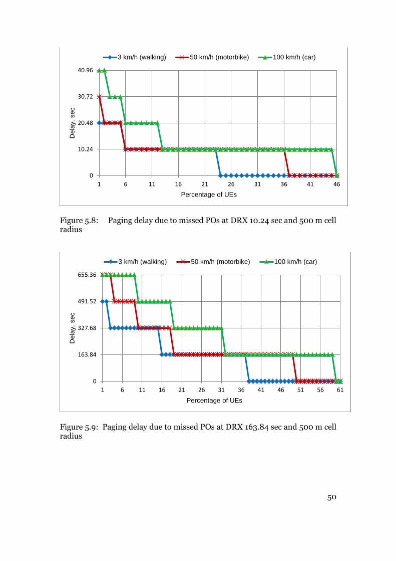
50
Figure 5.8: Paging delay due to missed POs at DRX 10.24 sec and 500 m cell radius
Figure 5.9: Paging delay due to missed POs at DRX 163.84 sec and 500 m cell radius
0
10.24
20.48
30.72
40.96
1 6 11 16 21 26 31 36 41 46
Dela
y, s
ec
Percentage of UEs
3 km/h (walking) 50 km/h (motorbike) 100 km/h (car)
0
163.84
327.68
491.52
655.36
1 6 11 16 21 26 31 36 41 46 51 56 61
Dela
y, s
ec
Percentage of UEs
3 km/h (walking) 50 km/h (motorbike) 100 km/h (car)

51
By extending the DRX cycle lengths, we can achieve lower energy consumption for UE. But due to the SFN misalignment between eNBs and eDRX, the UE experiences duplicate paging message reception and PO misses resulting in increased UE energy consumption and increased delay in paging reception or decreased UE reachability. Since UE wakes up only once at PF and PO within a DRX cycle, the network is also able to reach the UE only once during every DRX cycle. If the DRX cycles are extended, then the time interval for network to reach the UE is also extended. This time interval will increase further depending on the number of consecutive PO misses, shown in Figures A.6, A.7, and A.8 in Appendix A. As a result the UE may become less reachable. We compare average energy saving versus average paging delay due to missed POs for UEs travelling at 100 km/h across cells of 500 m radius, as shown in Figure 5.10.
Figure 5.10: Average energy consumption versus average paging delay due to missed POs by UEs at 100 km/h speed and 500 m cell radius
0
50
100
150
200
250
300
350
0
50
100
150
200
250
300
350
400
450
0.1 1 10 100
Dela
y, s
ec
Energ
y units
Thousands
DRX cycle length, sec
Energy consumption Paging delay at UE due to missed POs
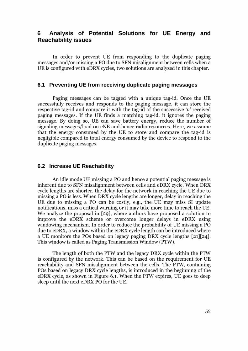
52
6 Analysis of Potential Solutions for UE Energy and Reachability issues
In order to prevent UE from responding to the duplicate paging messages and/or missing a PO due to SFN misalignment between cells when a UE is configured with eDRX cycles, two solutions are analyzed in this chapter.
6.1 Preventing UE from receiving duplicate paging messages
Paging messages can be tagged with a unique tag-id. Once the UE successfully receives and responds to the paging message, it can store the respective tag-id and compare it with the tag-id of the successive ‘n’ received paging messages. If the UE finds a matching tag-id, it ignores the paging message. By doing so, UE can save battery energy, reduce the number of signaling messages/load on eNB and hence radio resources. Here, we assume that the energy consumed by the UE to store and compare the tag-id is negligible compared to total energy consumed by the device to respond to the duplicate paging messages.
6.2 Increase UE Reachability
An idle mode UE missing a PO and hence a potential paging message is inherent due to SFN misalignment between cells and eDRX cycle. When DRX cycle lengths are shorter, the delay for the network in reaching the UE due to missing a PO is less. When DRX cycle lengths are longer, delay in reaching the UE due to missing a PO can be costly, e.g., the UE may miss SI update notifications, miss a critical warning or it may take more time to reach the UE. We analyze the proposal in [29], where authors have proposed a solution to improve the eDRX scheme or overcome longer delays in eDRX using windowing mechanism. In order to reduce the probability of UE missing a PO due to eDRX, a window within the eDRX cycle length can be introduced where a UE monitors the POs based on legacy paging DRX cycle lengths [21][24]. This window is called as Paging Transmission Window (PTW). The length of both the PTW and the legacy DRX cycle within the PTW is configured by the network. This can be based on the requirement for UE reachability and SFN misalignment between the cells. The PTW, containing POs based on legacy DRX cycle lengths, is introduced in the beginning of the eDRX cycle, as shown in Figure 6.1. When the PTW expires, UE goes to deep sleep until the next eDRX PO for the UE.

53
TX X X X X X X X X
POn POn+1
PTW
eDRX cycle length
Legacy DRX cycle length
Delayed UE PO due to
SFN misalignment in the cell
Figure 6.1: Illustration of PTW within eDRX cycle
The purpose of introducing a PTW in the beginning of eDRX cycle is two folds: to compensate for the SFN misalignment between eNB in the cells and to increase the probability that a network can reach the UE within a reasonable time frame even if the UE misses its PO in the new cell. For example, if the UE misses its eDRX POn in the new cell, it could still be made reachable via a legacy DRX POs within the PTW instead of UE’s next eDRX PO, i.e., POn+1. In order to appreciate the probability of increasing the chances of network reaching the UE in eDRX via PTW technique, we compare the probable delay that a UE could experience in non-PTW technique and PTW technique. In general, we have made the following assumptions in our analysis:
The radio is channel is robust.
The eNBs are misaligned by 10.24 sec, i.e. the SFN cycles between eNBs
are misaligned by 1023 radio frames.
The UE eDRX cycle length is 10.24 sec.
Since the SFN cycles between eNBs are misaligned by 1023 radio
frames, the PTW size is 10.24 sec.
eNB configures the PTW, such that window with legacy DRX cycle
lengths starts before the start of UE eDRX cycle.
The legacy DRX cycle length within PTW is 2.56 sec.
The delay calculation is done assuming the eDRX configured UE has
crossed from one cell to another (new) and stays in new cell for the rest
of eDRX duration.

54
Figure 6.2 illustrates an eDRX configured UE moving across cells whose SFN cycles are misaligned and without PTW technique configuration.
TXA D B
POn POn+1
eDRX
+5.12 sec- 5.12 sec10.24 sec
C
UE PO due to SFN misalignment
d1 d2
.
.
Figure 6.2: Illustration of UE reachability without PTW technique In the above illustration, let POn be the eDRX PO. For simplicity, we assume that the missed UE PO due to SFN misalignment occurs at midpoints within the misalignment window, i.e. at point C (before the UE eDRX PO) or D (after UE eDRX PO) in the illustration. But in reality, on an average the PO could be anywhere within ±SFN misalignment duration between eNBs. If P1 and P2 are the probabilities for POs at time C and D, then the probability of PO occurring at C and D is 0.5 each. Then the delay to reach the UE is a weighted average of the probabilities of the event and time duration till next UE eDRX PO. Delay = P1 * d1 + P2 * d2 Delay = 0.5 * 2.56 + 0.5 * (10.24 - 2.56) Delay = 5.12 sec By reducing the amount of SFN misalignment duration between eNBs in the cells, we can reduce the delay and hence increase the probability for network to reach the UE. In general, the weighted average delay for the network to reach the UE due to SFN misalignment between eNBs without PTW technique is given by:
Delay = ∑ 𝑃𝑖𝑑𝑛𝑖=1 𝑖
(6)
where, n = number of probable POs that could be possible within ±SFN misalignment duration. Pi = probability of ith UE PO within the ±SFN misalignment duration. di = average time duration between the ith UE PO and next eDRX PO.

55
Figure 6.3 illustrates an eDRX configured UE moving across cells whose SFN cycles are misaligned and configured with PTW technique.
TA B
POn POn+1eDRX
PTW
C D E
d1 d2 d3 d4Legacy DRX
.
.
.
.
UE PO due to SFN misalignment
Figure 6.3: Illustration of UE reachability with PTW technique In the above illustration, let POn be the eDRX PO. Within the PTW window (10.24 sec) the UE is configured with legacy DRX cycle lengths (2.56 sec). The PTW starts prior to the UE eDRX PO, POn. The legacy DRX POs within the PTW are A, C, D and E respectively. Again, for simplicity, we have assumed that the PO for the UE due to SFN misalignment occurs at midpoint within any of the legacy DRX cycle durations. If P1, P2, P3 and P4 are the probabilities for POs at time instants between legacy DRX cycle length durations, then the probabilities for these PO events are 0.25 each. The delay to reach the UE within the PTW is a weighted average of the probabilities of the PO event and time duration till next PO within the PTW. Delay = P1 * d1 + P2 * d2 + P3 * d3 + P4 * d4 Delay = 0.25 * 1.28 + 0.25 * 1.28 + 0.25 * 1.28 + 0.25 * 1.28 Delay = 1.28 sec As we can see, we can reduce the paging delay by 75 % using PTW technique. In this case, we can further reduce the delay by reducing SFN misalignment durations between eNBs (i.e. PTW size) and using shorter legacy DRX cycle lengths within PTW. In general, the weighted average delay for the network to reach the UE within PTW is given by:
Delay = ∑ 𝑃𝑖−𝑃𝑇𝑊𝑑𝑛𝑖=1 𝑖
(7)
where, n = number of probable POs that could be possible within PTW. Pi-PTW = probability of ith UE PO within PTW. di = average time duration between the ith UE PO and next legacy DRX PO within PTW.

56
We present a comparison of UE reachability in terms of network delay that a UE could experience due to SFN misalignment using both PTW technique and non-PTW technique. Figure 6.4 shows the delay due to a missed PO for both non-PTW and PTW technique with different legacy DRX cycle lengths for UEs travelling across cells of 500 meter radius. The size of SFN misalignment is 10.24 sec, eDRX cycle length is 10.24 sec and the PTW size is 10.24 sec in the analysis. As we can see from the Figure 6.4, we can reduce the network delay to reach the UE by using PTW technique significantly, as compared to non-PTW technique. Further, varying/reducing the length of legacy DRX cycles within PTW will increase the probability of network reaching the UE.
Figure 6.4: Comparison of network delay to reach the UE using no-PTW and PTW technique. eDRX=10.24 sec, PTW = 10.24 sec.
5.12
0
1
2
3
4
5
Dela
y, s
ec 75%
87%
93%
96%

57
Further, energy consumption can be reduced by having short DRX cycles within the PTW. But, looking at the PTW mechanism described above, one could argue: “why wouldn’t we spread out the number of relatively shorter DRX cycles across the eDRX sleeping period, since the UE is supposed to wake up the same number of times in both the cases, i.e. shorter DRX cycles spread over eDRX cycle versus short DRX cycles within PTW? To understand the energy saving via shorter DRX cycles rather than eDRX cycle configured with a PTW, we analyze the behavior of both the ideal and non-ideal paging DRX cycles [27] [28].
The ON period in an ideal DRX cycle has sharp rise and fall time or the
slope of the rise and fall time is zero. The ideal DRX cycle [27] is as shown in Figure 6.5, with power Pr = 1 unit/ms and TON = 1 ms, see Table 4.5.
DRX Cycle
T
Power
Ps
PrTON
tsleep
Figure 6.5: Ideal DRX cycle Source: [27] The total energy consumed by one ideal DRX cycle is,
Etotal-ideal = Pr * TON
(8)
Etotal-ideal = 1 unit But the ON period of a non-ideal DRX cycle has steep slopes and is divided into four parts via rise, sync, ON and fall times respectively [27], as shown in Figure 6.6.

58
DRX cycle
Pstsleep
trise
Tsync TON
tfall
Pr
T
Power
Modem active
Figure 6.6: Non-ideal DRX cycle
Rise time, trise: Before UE starts to demodulate DL signal, it needs time to initialize both the baseband and RF parts. For baseband, it initializes phase lock of baseband PLL synthesizer. For RF part, it needs time to stabilize AGC, initialize channel filters and also calibrate other parts [28].
Sync time, Tsync: During the sync time, UE performs demodulation of both primary and secondary synchronization signals, sent every 5 ms, decoding of PBCH for SFN information and also does channel estimation [28].
ON time, TON: During the ON time, UE modem is active and it is monitoring the PDCCH channel for paging message, if any.
Fall time, tfall: UE does not do any processing such as demodulation, calibration and time consuming tasks, but energy downs necessary hardware components [28].
Comparing the ideal versus non-ideal DRX cycle, we can see that the ON time, TON, remains the same, but the sleep time, tsleep, is reduced to accommodate rise, sync and fall times respectively. The three time
components, trise, Tsync and tfall, are directly dependent on DRX cycle lengths [27][28]. If the DRX cycle lengths are shorter, ≤ 40 ms, then the UE enters a
light sleep mode and awakes quickly, thus reducing the trise, Tsync and tfall,
times. In [27], it is estimated that if the DRX cycle lengths are very short, ≤ 20 ms, then the UE does not sleep at all. If the DRX cycle lengths are longer, ≥ 80
ms, then the UE enters deep sleep mode, thus increasing the trise, Tsync and
tfall, times. Because, in the deep sleep mode UE switches OFF the baseband,

59
RF and local oscillator and instead utilizes low precision clock for time synchronization [27]. But when the modem awakes, it consumes more time to reboot and consumes one LTE frame (10 ms) to achieve frequency synchronization via synchronization and reference signals respectively [27]. If the ON time, TON, is extended then UE is prevented from entering a deep sleep mode. In [27], the authors have calculated the following time values for a DRX
cycle length ≥ 80 ms: trise (26 ms), Tsync (21 ms), TON (1 ms) and tfall (21 ms).
But in reality the trise, Tsync and tfall value depends on the specific implementation from modem vendors. However, for analysis we use the time values from [27] for energy comparisons. The total energy consumed by one non-ideal DRX cycle is,
Etotal-real = Pr * trise + Pr * Tsync + Pr * TON + Pr * tfall (9)
Etotal-real = 45.5 units By considering the shape of a non-ideal DRX cycle length, we can achieve energy saving by having short wake-ups with shorter DRX cycles contained within PTW, i.e., with closely placed POs, as compared to spreading the POs across the sleep period in eDRX cycle. When the POs are closely placed or in succession we see that the ON periods of DRX cycles overlap each other, as shown in Figure 6.7. The fall time of the preceding ON period and the rise time of the consecutive ON period overlap. The overlapped area gives us opportunity to save energy. If the POs, in either legacy DRX cycles or short wake-ups, are to be spread across the eDRX sleeping period, then we would be consuming energy of the complete DRX cycle at each PO.
T
PowerOverlap area: opportunity for energy saving
Figure 6.7: Short wake-ups and ON period overlaps

60
We compare the energy consumed by non-overlapping versus overlapping DRX cycles, as shown in Figure 6.8. Here, we have assumed that the short wake-ups overlap at midpoint between fall time and rise time of the successive wake-ups. An example energy calculation is shown in Figure 6.8. By increasing the number of short wake-up POs within the PTW we can increase the probability of UE reachability for the network and also save energy. In general, the specific number of short wake-ups and their duration inside the PTW should be applied smartly depending on UE mobility characteristics such as speed, cell size, and acceptable paging delay for the UE and the length of SFN misalignment between the cells. By controlling the duration of each short wake-up in the successive short wake-ups, we can control the amount of energy saved via increasing or decreasing overlap area between the wake-ups.
Figure 6.8: Energy comparison for short wake-up POs
0
25
50
75
100
125
150
175
200
2 DRX cycles 3 DRX cycles 4 DRX cycles
Energ
y units
Non-overlapping DRX cycles Overlapping DRX cycles
17.21%
19.36%
12.9%

61

62
7 Conclusion and Future Work
In this chapter we summarize our work in brief and also make recommendations for future work.
7.1 Conclusion
We have addressed the impact on UE energy consumption and reachability, amount of signaling on eNB/network due to eDRX cycles and SFN misalignment between cells when the UE is configured with eDRX. The intention of applying eDRX cycles in idle mode is a straight forward way to reduce overall UE energy consumption. But the manner in which paging messages are delivered to an idle mode UE results in negative effects of increased energy consumption and reduced reachability for the UE. Paging messages are delivered at POs, which are dependent on SFN cycle in each eNB. When SFN between the eNBs are misaligned, the probability that a UE misses the PO increases, especially when DRX cycles are extended. As a result the UE may receive duplicate paging message and/or experience delayed paging message reception due to a PO miss. We addressed these two scenarios in our problem analysis and analyzed the impact of UE speed, cell size, and size of SFN misalignment together with DRX cycle lengths on paging handling in idle mode and its ultimate effect on UE energy consumption, reachability and signaling overhead.
The UE experiences increased number of events of either receiving the duplicate paging message multiple times and/or missing a PO when it’s moving faster across the cells. The number of events is relative to cell sizes. By extending the DRX cycle length, we can save UE energy due to extended sleep periods. By extending the cycle length beyond 10.24 sec’s we can save 90 % more energy as compared to cycle length of 0.32 sec’s. But due to UE receiving and responding to the duplicate paging messages multiple times at eDRX cycle lengths, the UE consumes more energy. When UE is configured with eDRX of 10.24 sec and moving across cells of radius of 500 m, UE receives 0.07, 0.11, and 0.15 percent of paging messages as duplicate paging messages at UE speed of 3 km/h, 50 km/h and 100 km/h respectively. This duplicate paging reception increase UE energy consumption by 2.31, 6.15 and 12 percent of the total energy units. Further, for every duplicate paging message there is cost of six additional messages which create load in the network. Also, responding to duplicate paging messages means unnecessary radio resource consumption between UE and eNB. The effect of missing a PO and thus receiving a delayed paging message reduces UE reachability for the network. Similarly, for UE configured with eDRX of 10.24 sec, moving across cells of radius 500 m, the percentage of PO misses are 0.34, 0.39, and 0.405 percent of the total POs at UE speed 3 km/h, 50 km/h and 100 km/h respectively. Extending the DRX cycle length when UE is at higher speed, forces the UE to experience missing their POs in succession. For the network, a missed PO

63
adds delay, in addition to UE DRX cycle length, for the network to reach the respective UE. Therefore, the subsequent paging receptions, after missing the PO, adds delay in communicating necessary information to the UEs, even critical information at times, resulting in reduced UE reachability. For example, when the SFN misalignment is at 0 to 1023 between eNBs, the average delay for the network to reach the UE are 2.31, 2.81 and 3.43 sec’s, which are measured at DRX cycle lengths of 10.24 sec for UE moving across cells of radius 500 m with 3 km/h, 50 km/h and 100 km/h speeds respectively. By reducing the duration of SFN misalignment between eNBs we can reduce the delay for network to reach the UE and hence increase UE reachability.
For eDRX configured UEs, it is necessary to overcome the effects of SFN misalignment and mobility related parameters on energy consumption and reachability. By applying PTW technique, we can reduce the network delay and thus increase UE reachability. Besides, we can also save UE energy consumption in PTW technique by using short wake-up POs. In general, applying eDRX cycles in idle is a way forward for reducing energy consumption for UE, but the effect of SFN misalignment between cells and UE mobility on paging handling adds up towards more energy consumption, signaling load and reduced UE reachability. As a result we see a need for tradeoff between energy saving and delay tolerance depending on mobility characteristic such as UE speed, cell size and the size of SFN misalignment between eNBs and also make smarter improvements in UE and network by incorporating PTW technique to save UE energy consumption and increase reachability.
7.2 Future Work
Our analysis of eDRX on UE energy consumption and reachability helped us to understand the implications of applying existing eDRX for UE under different situations, such as UE speed, cell size and eNB SFN misalignments. The problem scenario simulation is done by adapting a simplistic network setup to prove the effects of eDRX and SFN misalignment between eNBs on UE energy saving and reachability. We foresee that it’s possible to make several improvements and extend our work further to a large scale system setup with simulated network elements to match realistic network behavior. For example, we have assigned the starting SFN number in an SFN cycle for each eNB as a random number, to simulate SFN misalignment between eNBs. In a real network the start of SFN cycle could be based on co-ordination between each eNB or commanded from a central core network entity. The UE movement and activity can be made realistic with a dynamic traffic generator based on traces from real environment. Further, our study has considered only UE mobility within homogeneous cells. It will be interesting to see the behavior of paging reception or miss when UEs are mobile across heterogeneous cells, as the start of SFN cycles between such
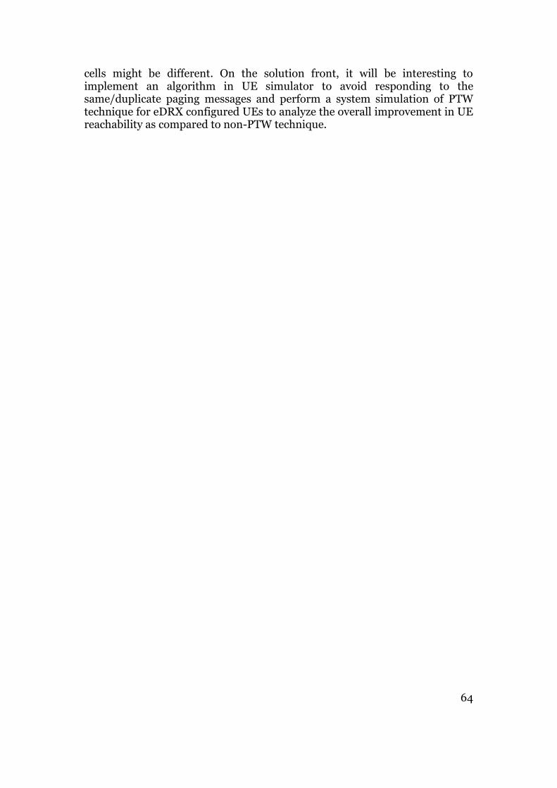
64
cells might be different. On the solution front, it will be interesting to implement an algorithm in UE simulator to avoid responding to the same/duplicate paging messages and perform a system simulation of PTW technique for eDRX configured UEs to analyze the overall improvement in UE reachability as compared to non-PTW technique.

65

66
References
[1] EARTH, Energy Aware Radio and neTwork tecHnologies. [Online]. Internet: http://www.ict-earth.eu/ [Mar.12,2015].
[2] Frenger, P.; Jading, Y.; Turk, J.; "A Case Study on Estimating Future
Radio Network Energy Consumption and CO2 Emissions", Personal, Indoor and Mobile Radio Communications (PIMRC Workshops), 24th International Symposium, IEEE, Sept. 2013, pp.1-5.
[3] EARTH, Energy Aware Radio and neTwork tecHnologies.
Deliverable D2.1, “Economic and Ecological Impact of ICT”. [Online]. Internet: https://bscw.ict-earth.eu/pub/bscw.cgi/d38532/EARTH_WP2_D2.1_v2.pdf [Mar.12,2015].
[4] 3GPP TR 22.868, “Study on Facilitating Machine to Machine Communication in 3GPP Systems”, Rel. 8, V. 8.0.0, Mar. 2007.
[5] Carroll, A.; Heiser, G.; “An Analysis of Power Consumption in a
Smartphone”. [Online]. Internet: https://www.usenix.org/legacy/event/atc10/tech/full_papers/Carroll.pdf [Mar.12,2015].
[6] Fowler, S.; "Study on Power Saving Based on Radio Frame in LTE
wireless Communication System using DRX", GLOBECOM Workshops, IEEE, Dec. 2011, pp.1062-1066.
[7] Arthur, Charles.; “How the Smartphone is Killing the PC”. [Online].
Internet: http://www.theguardian.com/technology/2011/jun/05/smartphones-killing-pc [Mar.12,2015].
[8] 3GPP TR 23.887, “Study on Machine-Type Communication (MTC)
and other Mobile Data Applications Communications Enhancements”, Rel. 12, V. 12.0.0, Dec. 2013.
[9] Alcatel-Lucent S.A., “The Impact of Small Cells on MME Signaling:
Methods to Reduce and Optimize MME Core Signaling caused by Small Cells”, Application Note, Oct. 2013.
[10] Jha, S.C.; Koc, A.T.; Gupta, M.; Vannithamby, R.; "Power Saving Mechanisms for M2M Communication over LTE networks", First International Conference on Communications and Networking, IEEE, Jul.2013, pp.102-106.

67
[11] Tirronen, T.; Larmo, A.; Sachs, J.; Lindoff, B.; Wiberg, N.; "Reducing Energy Consumption of LTE devices for Machine-to-Machine Communication", Globecom Workshops, IEEE, Dec.2012, pp.1650 - 1656.
[12] Qiu, Tao.; Xu, Haibo.; Zhou, Hua.; "Power Efficient Mechanism for MTC UEs in LTE-A Networks", Wireless Communications and Mobile Computing Conference, IEEE, Aug.2014, pp.751 - 755.
[13] Kim, Sangbum.; Jung, Kyunghun.; Choi, Jongsoo.; Kwak, Yongjun.; "Improving LTE/LTE-A UE Power Efficiency with Extended DRX cycle", 80th Vehicular Technology Conference, IEEE, Sep. 2014, pp.1-5.
[14] 3GPP TS 36.101, “E-UTRA: User Equipment (UE) Radio Transmission and Reception”, Rel. 12, V. 12.0.0, Jul. 2013.
[15] 3GPP TS 36.211, “E-UTRA: Physical Channels and Modulation”, Rel. 12, V. 12.4.0, Dec. 2014.
[16] Frenger, P.; Moberg, P.; Malmodin, J.; Jading, Y.; Godor, I.; "Reducing Energy Consumption in LTE with Cell DTX", Vehicular Technology Conference, IEEE, May.2011, pp.1-5.
[17] Dahlman, E.; Parkvall, S.; Skold, J.; Beming, P.; "3G Evolution HSPA and LTE for Mobile Broadband", Elsevier Ltd., 2007.
[18] Aho, K.; Puttonen, J.; Henttonen, T.; Dalsgaard, Lars.; "Channel Quality Indicator Preamble for Discontinuous Reception", Vehicular Technology Conference, IEEE, May.2010, pp.1-5.
[19] Bontu, C.S.; Illidge, E.; "DRX Mechanism for Power Saving in LTE", Communications Magazine, IEEE, Vol.47, No.6, Jan. 2009, pp 48 -55.
[20] 3GPP TS 36.321, “E-UTRA: Medium Access Control Protocol Specification”, Rel. 12, V. 12.3.0, Sep. 2014.
[21] 3GPP TS 36.331, “E-UTRA: Radio Resource Control Protocol Specification”, Rel. 12, V. 12.3.0, Sep. 2014.

68
[22] 3GPP TS 36.300, “E-UTRA and E-UTRAN: Overall description: Stage 2”, Rel. 12, V. 12.3.0, Sep. 2014.
[23] Liu, Liu.; She, Xiaoming.; Chen, Lan.; "Multi-user and channel dependent scheduling based adaptive power saving for LTE and beyond system", Asia-Pacific Conference on Communications, IEEE, Nov.2010, pp.118-122.
[24] 3GPP TS 36.304, “E-UTRA: User Equipment Procedures in Idle Mode”, Rel. 12, V. 12.2.0, Sep. 2014.
[25] 3GPP TS 24.301, "Non-Access-Stratum (NAS) protocol for Evolved Packet System (EPS)", Rel.13, V.13.0.0, Dec.2014
[26] 3GPP TS 36.413, "S1 Application Protocol (S1AP)", Rel.13, V.13.0.0, Jun.2015.
[27] Lauridsen, M.; Mogensen, P.; Noel, L.; "Empirical LTE Smartphone Power Model with DRX Operation for System Level Simulations", Vehicular Technology Conference, IEEE, Sep.2013, pp.1-6.
[28] Lauridsen, M.; Noël. L.; Sørensen, T.B.; Mogensen, P.; "An Empirical LTE Smartphone Power Model with a View to Energy Efficiency Evolution". [Online]. Internet: http://vbn.aau.dk/files/176790997/An_Empirical_LTE_Smartphone_Power_Model_with_a_View_to_Energy_Efficiency_Evolution.pdf [Nov.9, 2015].
[29] R2-157167, “Introducing extended DRX”, Qualcomm Incorporated, 3GPP TSG-RAN WG2 Meeting #92, CR 1988, Anaheim, USA, 16-20 Nov.2015.

69
Appendix A
In this Appendix we present the supplementary results which are used in our main result analysis and discussions. The figures are referenced from simulation results chapter and commented accordingly.
Figure A.1: Number of duplicate paging message receptions at 1000 m cell radius
Figure A.2: Number of duplicate paging message receptions at 1500 m cell radius
0
7
14
21
28
35
42
49
56
63
70
77
0.1 1 10 100Num
ber
of
duplic
ate
pagin
g m
essage
receptions
DRX cycle length, sec
3 km/h (walking) 50 km/h (motorbike) 100 km/h (car) SFN Aligned
0
7
14
21
28
35
42
49
56
63
70
77
0.1 1 10 100
Num
ber
of
duplic
ate
pagin
g m
essage
receptions
DRX cycle length, sec
3 km/h (walking) 50 km/h (motorbike) 100 km/h (car) SFN Aligned

70
Figure A.3: Number of missed POs at 1000 m cell radius
Figure A.4: Number of missed POs at 1500 m cell radius
0
7
14
21
28
35
42
49
56
63
0.1 1 10 100
Num
ber
of
mis
sed P
Os
DRX cycle length, sec
3 km/h (walking) 50 km/h (motorbike) 100 km/h (car) SFN Aligned
0
7
14
21
28
35
42
49
56
63
0.1 1 10 100
Num
ber
of
mis
sed P
Os
DRX cycle length, sec
3 km/h (walking) 50 km/h (motorbike) 100 km/h (car) SFN Aligned
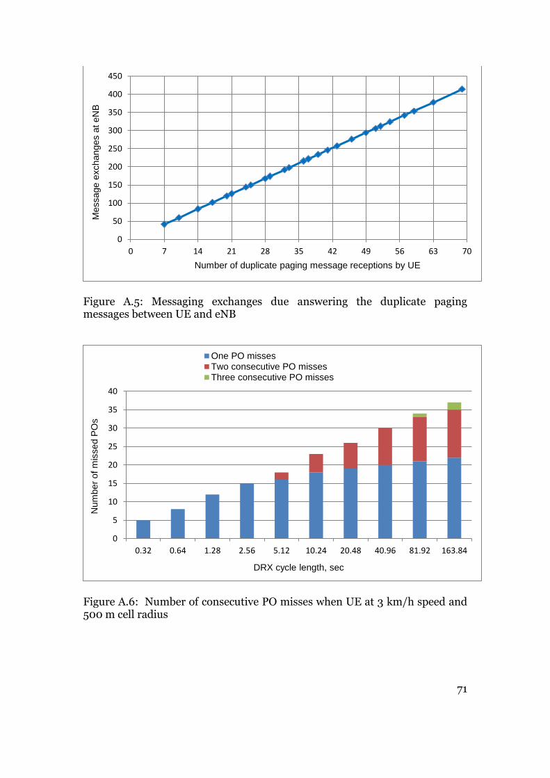
71
Figure A.5: Messaging exchanges due answering the duplicate paging messages between UE and eNB
Figure A.6: Number of consecutive PO misses when UE at 3 km/h speed and 500 m cell radius
0
50
100
150
200
250
300
350
400
450
0 7 14 21 28 35 42 49 56 63 70
Message e
xchanges a
t eN
B
Number of duplicate paging message receptions by UE
0
5
10
15
20
25
30
35
40
0.32 0.64 1.28 2.56 5.12 10.24 20.48 40.96 81.92 163.84
Num
ber
of
mis
sed P
Os
DRX cycle length, sec
One PO missesTwo consecutive PO missesThree consecutive PO misses

72
Figure A.7: Number of consecutive PO misses when UE at 50 km/h speed and 500 m cell radius
Figure A.8: Number of consecutive PO misses when UE at 100 km/h speed and 500 m cell radius
0
10
20
30
40
50
60
0.32 0.64 1.28 2.56 5.12 10.24 20.48 40.96 81.92 163.84
Num
ber
of
mis
sed P
Os
DRX cycle length, sec
One PO missesTwo consecutive PO missesThree consecutive PO misses
0
10
20
30
40
50
60
70
0.32 0.64 1.28 2.56 5.12 10.24 20.48 40.96 81.92 163.84
Num
ber
of
mis
sed P
Os
DRX cycle length, sec
One PO missesTwo consecutive PO missesThree consecutive PO misses
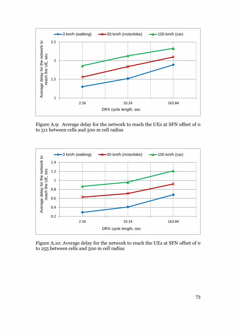
73
Figure A.9: Average delay for the network to reach the UEs at SFN offset of 0 to 511 between cells and 500 m cell radius
Figure A.10: Average delay for the network to reach the UEs at SFN offset of 0 to 255 between cells and 500 m cell radius
1
1.5
2
2.5
2.56 10.24 163.84
Avera
ge d
ela
y fo
r th
e n
etw
ork
to
reach t
he U
E,
sec
DRX cycle length, sec
3 km/h (walking) 50 km/h (motorbike) 100 km/h (car)
0.2
0.4
0.6
0.8
1
1.2
1.4
2.56 10.24 163.84
Avera
ge d
ela
y fo
r th
e n
etw
ork
to
reach t
he U
E,
sec
DRX cycle length, sec
3 km/h (walking) 50 km/h (motorbike) 100 km/h (car)

TRITA-ICT-EX-2016:126