Embed Size (px)
Citation preview
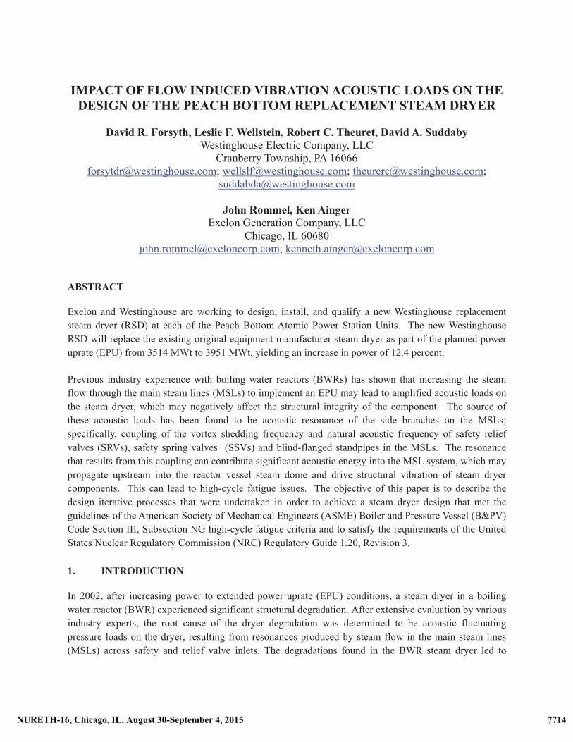
IMPACT OF FLOW INDUCED VIBRATION ACOUSTIC LOADS ON THE
DESIGN OF THE PEACH BOTTOM REPLACEMENT STEAM DRYER
David R. Forsyth, Leslie F. Wellstein, Robert C. Theuret, David A. Suddaby Westinghouse Electric Company, LLC
Cranberry Township, PA 16066 [email protected]; [email protected]; [email protected];
John Rommel, Ken Ainger Exelon Generation Company, LLC
Chicago, IL 60680 [email protected]; [email protected]
ABSTRACT
Exelon and Westinghouse are working to design, install, and qualify a new Westinghouse replacement
steam dryer (RSD) at each of the Peach Bottom Atomic Power Station Units. The new Westinghouse RSD will replace the existing original equipment manufacturer steam dryer as part of the planned power uprate (EPU) from 3514 MWt to 3951 MWt, yielding an increase in power of 12.4 percent.
Previous industry experience with boiling water reactors (BWRs) has shown that increasing the steam flow through the main steam lines (MSLs) to implement an EPU may lead to amplified acoustic loads on the steam dryer, which may negatively affect the structural integrity of the component. The source of these acoustic loads has been found to be acoustic resonance of the side branches on the MSLs; specifically, coupling of the vortex shedding frequency and natural acoustic frequency of safety relief valves (SRVs), safety spring valves (SSVs) and blind-flanged standpipes in the MSLs. The resonance that results from this coupling can contribute significant acoustic energy into the MSL system, which may propagate upstream into the reactor vessel steam dome and drive structural vibration of steam dryer components. This can lead to high-cycle fatigue issues. The objective of this paper is to describe the design iterative processes that were undertaken in order to achieve a steam dryer design that met the guidelines of the American Society of Mechanical Engineers (ASME) Boiler and Pressure Vessel (B&PV) Code Section III, Subsection NG high-cycle fatigue criteria and to satisfy the requirements of the United States Nuclear Regulatory Commission (NRC) Regulatory Guide 1.20, Revision 3.
1. INTRODUCTION
In 2002, after increasing power to extended power uprate (EPU) conditions, a steam dryer in a boiling water reactor (BWR) experienced significant structural degradation. After extensive evaluation by various industry experts, the root cause of the dryer degradation was determined to be acoustic fluctuating pressure loads on the dryer, resulting from resonances produced by steam flow in the main steam lines (MSLs) across safety and relief valve inlets. The degradations found in the BWR steam dryer led to
7715NURETH-16, Chicago, IL, August 30-September 4, 2015 7714NURETH-16, Chicago, IL, August 30-September 4, 2015
changes to NRC Regulatory Guide 1.20 (Reference [1]), requiring plants to evaluate their steam dryers before any planned increase in power level above their presently licensed power level.
Exelon Generation Company, LLC is implementing an extended power uprate (EPU) project to increase plant power uprate from 3514 MWt to 3951 MWt, yielding an increase in power of 12.4 percent, at the Peach Bottom Atomic Power Stations Units 2 and 3. Included in this EPU project is the replacement of the existing parallel plane steam dryers with Westinghouse 3-ring octagonal replacement steam dryers. The Westinghouse 3-ring replacement design has improved performance compared to existing steam dryers. To satisfy the requirements of the United States Nuclear Regulatory Commission (NRC) Regulatory Guide 1.20, Revision 3, analyses were performed during the design and fabrication process to demonstrate the structural integrity of the steam dryer at EPU conditions. These analyses included the determination of acoustic loads due to possible resonance of any standpipes on the MSLs and involved multiple acoustic and structural analyses, scale model testing, the collection of plant specific data and several computer codes. These codes are both commercially available and special-purpose codes developed in conjunction with the prediction and evaluation of acoustic loads.
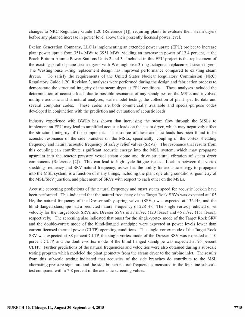
Industry experience with BWRs has shown that increasing the steam flow through the MSLs to implement an EPU may lead to amplified acoustic loads on the steam dryer, which may negatively affect the structural integrity of the component. The source of these acoustic loads has been found to be acoustic resonance of the side branches on the MSLs; specifically, coupling of the vortex shedding frequency and natural acoustic frequency of safety relief valves (SRVs). The resonance that results from this coupling can contribute significant acoustic energy into the MSL system, which may propagate upstream into the reactor pressure vessel steam dome and drive structural vibration of steam dryer components (Reference [2]). This can lead to high-cycle fatigue issues. Lock-in between the vortex shedding frequency and SRV natural frequency, as well as the ability for acoustic energy to propagate into the MSL system, is a function of many things, including the plant operating conditions, geometry of the MSL/SRV junction, and placement of SRVs with respect to each other on the MSLs.
Acoustic screening predictions of the natural frequency and onset steam speed for acoustic lock-in have been performed. This indicated that the natural frequency of the Target Rock SRVs was expected at 105 Hz, the natural frequency of the Dresser safety spring valves (SSVs) was expected at 132 Hz, and the blind-flanged standpipe had a predicted natural frequency of 228 Hz. The single vortex predicted onset velocity for the Target Rock SRVs and Dresser SSVs is 37 m/sec (120 ft/sec) and 46 m/sec (151 ft/sec), respectively. The screening also indicated that onset for the single-vortex mode of the Target Rock SRV and the double-vortex mode of the blind-flanged standpipe were expected at power levels lower than current licensed thermal power (CLTP) operating conditions. The single-vortex mode of the Target Rock SRV was expected at 88 percent CLTP, the single-vortex mode of the Dresser SSV was expected at 110 percent CLTP, and the double-vortex mode of the blind flanged standpipe was expected at 95 percent CLTP. Further predictions of the natural frequencies and velocities were also obtained during a subscale testing program which modeled the plant geometry from the steam dryer to the turbine inlet. The results from this subscale testing indicated that acoustics of the side branches do contribute to the MSL alternating pressure signature and the side branch natural frequencies measured in the four-line subscale test compared within 7-8 percent of the acoustic screening values.
�
7716NURETH-16, Chicago, IL, August 30-September 4, 2015 7715NURETH-16, Chicago, IL, August 30-September 4, 2015
2. DESIGN OF WESTINGHOUSE STEAM DRYERS
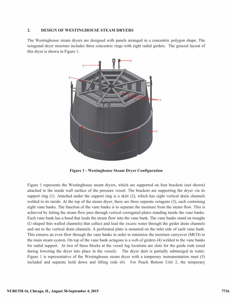
The Westinghouse steam dryers are designed with panels arranged in a concentric polygon shape. The octagonal dryer structure includes three concentric rings with eight radial girders. The general layout of this dryer is shown in Figure 1. �
�
Figure 1 - Westinghouse Steam Dryer Configuration �
Figure 1 represents the Westinghouse steam dryers, which are supported on four brackets (not shown) attached to the inside wall surface of the pressure vessel. The brackets are supporting the dryer via its support ring (1). Attached under the support ring is a skirt (2), which has eight vertical drain channels welded to its inside. At the top of the steam dryer, there are three separate octagons (3), each containing eight vane banks. The function of the vane banks is to separate the moisture from the steam flow. This is achieved by letting the steam flow pass through vertical corrugated plates standing inside the vane banks. Each vane bank has a hood that leads the steam flow into the vane bank. The vane banks stand on troughs (U-shaped thin walled channels) that collect and lead the excess water through the girder drain channels and out to the vertical drain channels. A perforated plate is mounted on the inlet side of each vane bank. This ensures an even flow through the vane banks in order to minimize the moisture carryover (MCO) to the main steam system. On top of the vane bank octagons is a web of girders (4) welded to the vane banks for radial support. At two of these blocks at the vessel lug locations are slots for the guide rods (used during lowering the dryer into place in the vessel). The dryer skirt is partially submerged in water. Figure 1 is representative of the Westinghouse steam dryer with a temporary instrumentation mast (5) included and separate hold down and lifting rods (6). For Peach Bottom Unit 2, the temporary
7717NURETH-16, Chicago, IL, August 30-September 4, 2015 7716NURETH-16, Chicago, IL, August 30-September 4, 2015
instrumentation mast, which is attached to the top of the dryer, will be removed after one cycle of operation.
3. DESIGN CONSIDERATIONS
Reactor internals components, including the steam dryer, must be designed to meet the requirements of the applicable NRC General Design Criteria (GDC), commensurate with their safety function. Although some internals components, such as the steam dryers, perform no safety function, they must retain their structural integrity to avoid generation of loose parts that may adversely impact the capability of other systems, structures, and components (SSCs) to perform their safety function. The structural analysis for the steam dryer consists of two components: (1) the acoustic loads on the dryer generated as a result of dynamic steam flow effects in the MSLs and in the reactor pressure vessel steam dome, and (2) the non-acoustic loads such as deadweight, differential pressure, and seismic. During the design/analysis process, a number of design changes were incorporated as a result of the dynamic steam flow effects in the MSLs and the reactor pressure vessel steam dome. The major design changes were: a) Rotation of Steam Dryer Within the Reactor Pressure Vessel, b) Incorporation of Upper and Lower Belts in the Lower Portion of the Steam Dryer, c) Incorporation of Divider Plates and d) Changes in the Lifting Bracket Design.
3.1 Rotation of Steam Dryer Within the Reactor Pressure Vessel
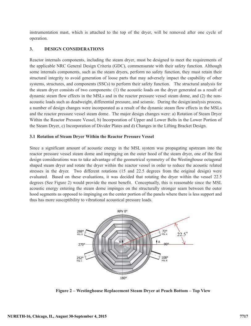
Since a significant amount of acoustic energy in the MSL system was propagating upstream into the reactor pressure vessel steam dome and impinging on the outer hood of the steam dryer, one of the first design considerations was to take advantage of the geometrical symmetry of the Westinghouse octagonal shaped steam dryer and rotate the dryer within the reactor vessel in order to reduce the acoustic related stresses in the dryer. Two different rotations (15 and 22.5 degrees from the original design) were evaluated. Based on these evaluations, it was decided that rotating the dryer within the vessel 22.5 degrees (See Figure 2) would provide the most benefit. Conceptually, this is reasonable since the MSL acoustic energy entering the steam dome impinges on the structurally stronger seam between the outer hood segments as opposed to impinging on the center portion of the panels where there is less support and thus has more susceptibility to vibrational acoustical pressure loads.
Figure 2 – Westinghouse Replacement Steam Dryer at Peach Bottom – Top View
7718NURETH-16, Chicago, IL, August 30-September 4, 2015 7717NURETH-16, Chicago, IL, August 30-September 4, 2015
3.2 Incorporation of Upper and Lower Belts in the Lower Portion of the Steam Dryer
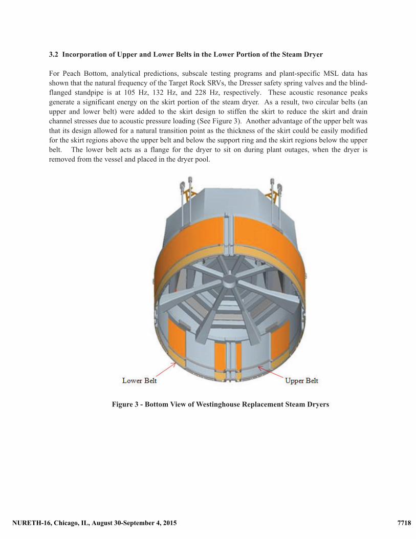
For Peach Bottom, analytical predictions, subscale testing programs and plant-specific MSL data has shown that the natural frequency of the Target Rock SRVs, the Dresser safety spring valves and the blind-flanged standpipe is at 105 Hz, 132 Hz, and 228 Hz, respectively. These acoustic resonance peaks generate a significant energy on the skirt portion of the steam dryer. As a result, two circular belts (an upper and lower belt) were added to the skirt design to stiffen the skirt to reduce the skirt and drain channel stresses due to acoustic pressure loading (See Figure 3). Another advantage of the upper belt was that its design allowed for a natural transition point as the thickness of the skirt could be easily modified for the skirt regions above the upper belt and below the support ring and the skirt regions below the upper belt. The lower belt acts as a flange for the dryer to sit on during plant outages, when the dryer is removed from the vessel and placed in the dryer pool.
Figure 3 - Bottom View of Westinghouse Replacement Steam Dryers
7719NURETH-16, Chicago, IL, August 30-September 4, 2015 7718NURETH-16, Chicago, IL, August 30-September 4, 2015
3.3 Incorporation of Divider Plates
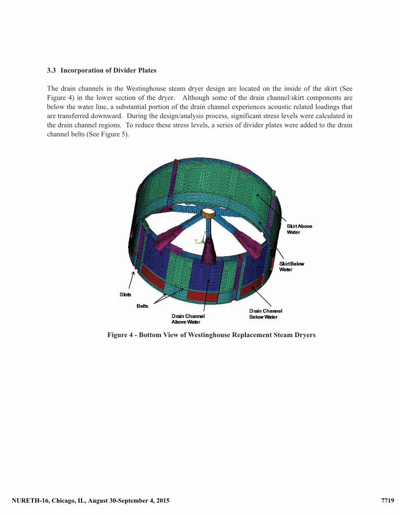
The drain channels in the Westinghouse steam dryer design are located on the inside of the skirt (See Figure 4) in the lower section of the dryer. Although some of the drain channel/skirt components are below the water line, a substantial portion of the drain channel experiences acoustic related loadings that are transferred downward. During the design/analysis process, significant stress levels were calculated in the drain channel regions. To reduce these stress levels, a series of divider plates were added to the drain channel belts (See Figure 5).
Figure 4 - Bottom View of Westinghouse Replacement Steam Dryers
7720NURETH-16, Chicago, IL, August 30-September 4, 2015 7719NURETH-16, Chicago, IL, August 30-September 4, 2015
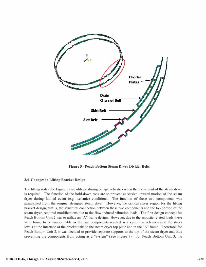
Figure 5 - Peach Bottom Steam Dryer Divider Belts �
3.4 Changes in Lifting Bracket Design
The lifting rods (See Figure 6) are utilized during outage activities when the movement of the steam dryer is required. The function of the hold-down rods are to prevent excessive upward motion of the steam dryer during faulted event (e.g., seismic) conditions. The function of these two components was maintained from the original designed steam dryer. However, the critical stress region for the lifting bracket design, that is, the structural connection between these two components and the top portion of the steam dryer, required modifications due to the flow induced vibration loads. The first design concept for Peach Bottom Unit 2 was to utilize an “A” frame design. However, due to the acoustic related loads these were found to be unacceptable as the two components reacted as a system which increased the stress levels at the interface of the bracket tabs to the steam dryer top plate and in the “A” frame. Therefore, for Peach Bottom Unit 2, it was decided to provide separate supports to the top of the steam dryer and thus preventing the components from acting as a “system” (See Figure 7). For Peach Bottom Unit 3, the
7721NURETH-16, Chicago, IL, August 30-September 4, 2015 7720NURETH-16, Chicago, IL, August 30-September 4, 2015
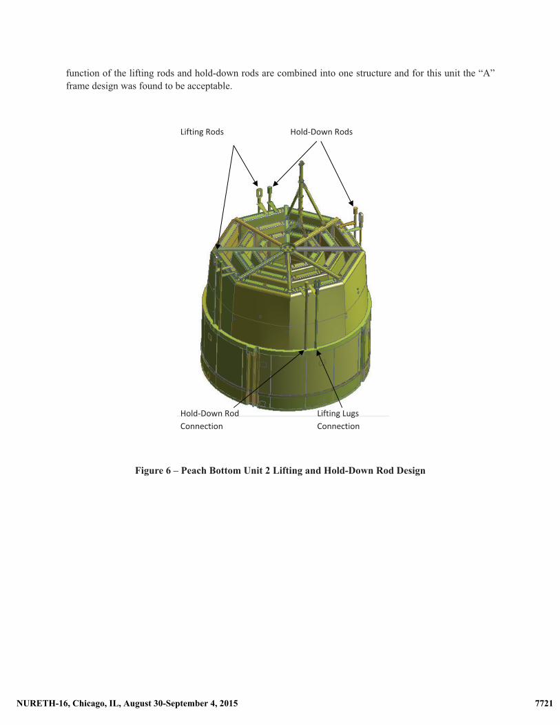
function of the lifting rods and hold-down rods are combined into one structure and for this unit the “A” frame design was found to be acceptable.
Figure 6 – Peach Bottom Unit 2 Lifting and Hold-Down Rod Design
Lifting�Rods�
Lifting�LugsConnection
Hold�Down�Rods
Hold�Down�Rod�Connection�
7722NURETH-16, Chicago, IL, August 30-September 4, 2015 7721NURETH-16, Chicago, IL, August 30-September 4, 2015
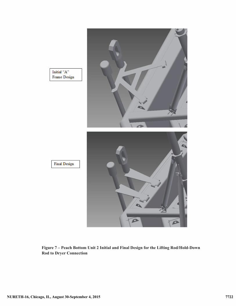
Figure 7 – Peach Bottom Unit 2 Initial and Final Design for the Lifting Rod/Hold-Down Rod to Dryer Connection
7723NURETH-16, Chicago, IL, August 30-September 4, 2015 7722NURETH-16, Chicago, IL, August 30-September 4, 2015
3.5 Impact of Changes in Upper Dryer Mass on Lower Dryer Component Stresses
The steam dryer consists of two major sections. The first section constitutes the upper portion of the dryer and includes the inner, middle and outer hoods, girder system and vane banks. The second section consists of the skirt structure, drain channels and upper and lower belts. In an effort to reduce stresses in the hoods, the hood thicknesses were increased. While this did change the hood natural frequencies and reduced the hood stresses, there was a negative impact on the stress levels in the lower portion of the dryer (e.g., skirt, belts, etc.). This means that the portions of the steam dryer above and below the support ring are coupled. As a result, iterations were performed to balance the stress improvements found in the upper portion of the dryer with its’ increased mass with the stress levels in the lower portion of the dryer. The final design selected was to incorporate a taper (as a function of elevation) in the thickness of the outer hood to obtain the maximum benefit for stress levels in the outer hood component and to reduce the increased upper dryer mass and thus minimize the resulting increased stress levels for the lower dryer components (e.g., skirt, skirt to belt interfaces, etc.).
4. ANALYSIS METHODS
A critical step in the design change process was the utilization of commercially available finite element analysis computer codes and special codes that were specifically developed to evaluate acoustic loads and their impact on the steam dryer. The finite element modeling techniques to quantify critical frequencies were validated by comparing the results of the finite element modeling to the results from a full-scale steam dryer vibration test. Using these codes, cumulative stress plots as a function of frequency were generated for each of the critical steam dryer components. This allowed the designers/analysts to make design changes to specifically address and/or change the response of the components at selected frequencies for each of the components. It is important to note that design changes (e.g. the addition of the divider plates), while reducing the stress levels in the local region, in many cases also changed (and in some cases increased) the stress levels in other parts of the steam dryer. As a result, significant care was taken in selecting design changes in order to reduce the number of design/analytical iterations. Another critical consideration in the design change process was to maintain the weight of the steam dryer to an acceptable value. In all of the above described design changes, the impact of these changes were significant in that the original design stress levels significantly exceeded the 13,600 psi high cycle fatigue endurance limit for the dryer components and that, after the modifications were incorporated, these stress levels were determined to be significantly lower than the American Society of Mechanical Engineers Boiler and Pressure Vessel Code Section III, Subsection NG high-cycle fatigue code allowables.
5. CONCLUSIONS
Exelon and Westinghouse are working to design, install, and qualify a new Westinghouse replacement steam dryer (RSD) at each of the Peach Bottom Atomic Power Station Units. As a result of acoustic resonance of the side branches on the main steam lines (MSLs) due to the coupling of the vortex shedding frequency and natural acoustic frequency of safety relief valves (SRVs), safety spring valves (SSVs) and blind-flanged standpipes in the MSLs, a number of design changes to the steam dryer design were necessary. With these changes the steam dryer design met the guidelines of the American Society of Mechanical Engineers (ASME) Boiler and Pressure Vessel (B&PV) code, Section III, Subsection NG high-cycle fatigue criteria and the requirements of the United States Nuclear Regulatory Commission (NRC) Regulatory Guide 1.20, Revision 3.�
7724NURETH-16, Chicago, IL, August 30-September 4, 2015 7723NURETH-16, Chicago, IL, August 30-September 4, 2015
6. REFERENCES
[1] “Comprehensive Vibration Assessment Program for Reactor Internals During Preoperational and Initial Startup Testing”, U.S. Nuclear Regulatory Commission, Regulatory Guide 1.20, Revision 3, March 2007.
[2] S. A. Hambric, T. M. Mulcahy, V. N. Shah, T. Scarbrough and C. Wu, “Flow-Induced Vibration
Effects on Nuclear Power Plant Components Due to Main Steam Line Valve Singing”, Proceedings of the Ninth NRC/ASME Symposium on Valves, Pumps and Inservice Testing, NUREG/CP-0152, Vol. 6, Pages 3B:49 – 3B:69, July 17-19, 2006
7725NURETH-16, Chicago, IL, August 30-September 4, 2015 7724NURETH-16, Chicago, IL, August 30-September 4, 2015