Embed Size (px)
Citation preview

Impact of mechanical heterogeneity on joint density in a welded ignimbrite 1
A.M. Soden*, R.J. Lunn1 and Z.K. Shipton1 2
School of Geographical and Earth Sciences, University of Glasgow, Glasgow, G12 8QQ, UK 3
1Department of Civil & Environmental Engineering, University of Strathclyde, Glasgow, G1 1XJ, UK 4
5
Abstract 6
Joints are conduits for groundwater, hydrocarbons and hydrothermal fluids. Robust fluid flow models 7
rely on accurate characterisation of joint networks, in particular joint density. It is generally assumed 8
that the predominant factor controlling joint density in layered stratigraphy is the thickness of the 9
mechanical layer where the joints occur. Mechanical heterogeneity within the layer is considered a 10
lesser influence on joint formation. We analysed the frequency and distribution of joints within a 11
single 12-meter thick ignimbrite layer to identify the controls on joint geometry and distribution. The 12
observed joint distribution is not related to the thickness of the ignimbrite layer. Rather, joint initiation, 13
propagation and termination are controlled by the shape, spatial distribution and mechanical properties 14
of fiamme, which are present within the ignimbrite. The observations and analysis presented here 15
demonstrate that models of joint distribution, particularly in thicker layers, that do not fully account for 16
mechanical heterogeneity are likely to underestimate joint density, the spatial variability of joint 17
distribution and the complex joint geometries that result. Consequently, we recommend that 18
characterisation of a layer’s compositional and material properties improves predictions of subsurface 19
joint density in rock layers that are mechanically heterogeneous. 20
1. Introduction 21
The accurate characterisation of fracture attributes is essential for constraining fracture network 22
models and, as a consequence, for improving predictions of fluid flow in fractured rocks. Such flow 23
predictions can be key to assessing the viability of individual sites for industrial production, as for 24
example, in assessing aquifer recharge for groundwater production schemes (Neuman, 2005; Jimenez-25
Martinez et al., 2013), determining the viability of enhanced geothermal systems (Fox et al., 2013; 26
Hofmann et al., 2014) and determining hydrocarbon production prospects in tight reservoirs (Koning, 27
2003). Stochastic or mechanical models that predict fracture distribution and geometry at depth are 28
more reliable if they include information and interpretations about the manner in which fracture 29
initiation, growth and arrest are affected by variables such as rock strength, anisotropy, stress state and 30
fluid pressure (Cacas et al., 2001). 31

Predictive models of joint density generally focus on the thickness of the jointing layer, as commonly 32
observed in layered sedimentary rocks where opening-mode joints occur as laterally persistent, layer-33
confined, parallel sets, with a positive correlation between median joint spacing and mechanical layer 34
thickness. (Huang and Angelier, 1989, Narr and Suppe, 1991; Gross, 1993; Ji and Saruwatari, 1998; Ji 35
et al., 1998; Fisher and Polansky, 2006). However, factors other than layer thickness also affect the 36
number and geometry of joints within a layer. Principal among these is the mechanical heterogeneity 37
of the layer, that is a factor overlooked in many numerical models of joint formation, which apply only 38
to isotropic, homogeneous layers. In reality, rocks are spatially heterogeneous, varying in both 39
composition and mechanical properties. Several workers have shown that mechanical heterogeneities 40
in the form of flaws or inclusions are sites of joint initiation in rock. Inclusions such as fossils and 41
intraclasts and flaws in the form of pores, bed forms and microcracks (Pollard and Aydin, 1988; Gross, 42
1993; McConaughy and Engelder, 2001; Weinberger, 2001a) perturb the regional stress field and act 43
to concentrate stress at the flaw until it exceeds the tensile strength of the rock, promoting joint 44
initiation and propagation. When an inclusion is weaker than the surrounding rock, the stress 45
concentration is tangential to the inclusion, for stronger inclusions the tensile stress is greater within 46
the inclusion and the tangential stress less (Pollard and Aydin, 1988). Futhermore, inclusions can 47
localise stress at the greatest point of curvature i.e. at ‘corners’ or ‘tips’ (Eshelby, 1957, 1959; Pollard 48
and Aydin, 1988). Hence, flaw distribution, size, shape and material properties affect the density, 49
average spacing and saturation of joints in a rock layer (Weinberger, 2001b; Tuckwell et al., 2003) 50
Mechanical heterogeneity not only controls joint initiation and propagation but also impacts joint 51
geometry. In homogeneous material, joint propagation is proposed to occur by coalescing of 52
microcracks in the process zone ahead of the joint tip (Scholz, 1993) resulting in planar joints. By 53
contrast, observations of joints at sedimentary interfaces show that joints can step across, bifurcate or 54
propagate straight through them (Cooke and Underwood, 2001; Larsen et al., 2010). Numerical 55
modelling of this process demonstrates that as a fracture tip approaches an interface, two stress 56
maxima occur ahead and either side of the fracture tip (Cooke and Underwood, 2001) resulting in a 57
step-wise propagation of the joint, rather than a simple continuing coalescence for a migrating process 58
zone. 59
In this study, we examine the manner in which the spatial distribution and geometry of joints in a 12-60
meter thick densely welded ignimbrite layer are affected by the geometrical and mechanical 61
characteristics of heterogeneities in the form of fiamme, which create mechanical heterogeneities 62
within the lithology. Although layering has been shown to play a significant role in the spatial 63
distribution of joints; in the absence of strong layering, mechanical heterogeneity within, may exert a 64
strong influence on joint network development. Our study is an example of how spatially 65

heterogeneous rock strength impacts joint development and the properties of the resultant joint 66
network. 67
The observations and analysis presented here demonstrate that models of joint distribution, particularly 68
in thicker layers, that do not fully account for mechanical heterogeneity are likely to underestimate 69
joint density, the spatial variability of joint distribution and the complex joint geometries that result. 70
Our observations may also serve as an analogue for understanding the affect mechanical 71
heterogeneities can have on joint networks in layered sedimentary sequences. 72
2. Formation and properties of ignimbrites 73
The formation of ignimbrite deposits is a complex process that has significant impact on their 74
mechanical properties. Key factors are ‘welding’; glass transition temperature; and syn- and post-75
cooling alteration processes. Welding refers to the syn- and post-depositional viscous deformation, 76
fusion and compaction (‘flattening’) of glass shards, lapilli and pumice clasts, which post-compaction 77
are known as fiamme (Grunder and Russell, 2005; Bull and McPhie, 2007). The welding process 78
sinters and fuses particles together and decreases porosity, so that high degrees of welding (i.e. densely 79
welded) correlate with increased unconfined compressive strength (Moon, 1993; Schultz and Li, 1995; 80
Quane and Russell, 2005). The degree to which an ignimbrite is welded can be evaluated by measuring 81
fiamme aspect ratio (Ragan and Sheridan, 1972; Kobberger and Schmincke, 1999). Fiamme in 82
moderately-to-densely welded deposits have aspect ratios between 4 and 5 (Quane and Russell, 2005), 83
these fiamme form a fabric of discontinuous layers, or eutaxitic texture, parallel or sub-parallel to the 84
unit base. Poorly welded ignimbrites have fiamme aspect ratios less than 4 and a very poorly 85
developed euxtaxitic texture. 86
The base of an ignimbrite is commonly marked by a vitrophyre, a massive fine-grained glassy layer 87
formed by rapid cooling of the pyroclastic material. Generally, the vitrophyre is devitrified to a yellow, 88
brittle, fine-grained powder (Ross and Smith, 1961). An ignimbrite may be composed of one or 89
multiple ash-flows. If each ash-flow has been emplaced in rapid succession then the whole body of 90
material will cool as a single cooling unit or layer (Smith et l., 1994; Wilson et al., 2003). However, as 91
the unit cools the level of welding compaction varies vertically and depends upon the duration over 92
which the glassy shards and pumice remain viscous (Quane and Russell, 2005; Riehle et al., 2010). 93
These vertical variations in welding describe the welding profile of an ignimbrite The ideal welding 94
profile for a ignimbrite unit comprises a poorly welded (i.e. low density and high porosity) base and 95
top, formed by rapid cooling and thus limited compaction. In the lower half of the unit, slower cooling 96
permits high degrees of welding compaction (i.e. high density and low porosity) (Quane and Russel, 97

2005 and references therein). In reality, a variety of ignimbrite welding profiles have been found 98
including densely welded throughout (Henry and Wolff, 1992), densely welded lower half with a 99
gradual decrease in compaction upward (Kobberger and Schmincke, 1999; Jutzeler et al., 2010) or 100
multiple welding maxima and minima within the unit (Riehle et., 2010). The change between the 101
welding facies is gradational. Commonly, the material at the top of the unit is increasingly ash rich and 102
fiamme poor, recording the waning of the eruptive phase. 103
Deformation within an ignimbrite changes from ductile to brittle as cooling proceeds. Once welding 104
compaction ceases, thermal stresses are relieved by the formation of columnar cooling joints (DeGraff 105
and Aydin, 1993; Kobberger and Schmincke, 1999; Goehring and Morris, 2008; Sewell et al., 2012). 106
The temperature at which this ductile-brittle transition occurs is known as the glass transition 107
temperature (Tg), (Giordano et al., 2005) and demarcates the cooling front within the layer. The time 108
taken for a deposit to cool below Tg depends on several factors including the composition and initial 109
temperature of the pyroclastic flow, flow layer thickness and substrate temperature (Ragan and 110
Sheridan, 1972; Riehle, 1973; Miller and Riehle, 1994). For example, Riehle (1973) calculated that a 111
10m-thick rhyolitic pyroclastic flow will cool to half its initial temperature within 2 years while a 40m-112
thick layer requires 20 years. 113
Cooling joints initiate at the top and bottom of the unit and follow the cooling front toward the unit 114
interior, forming elongate, regularly and spaced, polygonal columns with ~ 120 angles between joints 115
(Goehring and Morris, 2008). Joint advancement is incremental, alternating between brittle joint 116
propagation behind the cooling front and termination in the plastic medium beyond the cooling front. 117
Consequently, the cooling joint surface is composed of sub-horizontal smooth (brittle) and rough 118
(plastic) sections creating undulations or stria on the joint surface (Goehring and Morris, 2008). 119
Mineralisation or alteration on or immediately around the cooling joint surface may also occur (Dunne 120
et al., 2003). 121
Syn- and post-cooling secondary alteration processes can further alter the material properties of the 122
ignimbrite. Vapour phase crystallisation precipitates minerals from hot gases, filling pore spaces in the 123
ash matrix or pumice vesicles. Crystals grow discretely or as meshworks (McArthur et al., 1998), thus 124
strengthening the matrix by reducing pore space and growth of interlocking crystals. Vapour phase 125
alteration breaks down the glassy fiamme material to form either discrete acicular crystals growing 126
inward from the fiamme rim or spherical intergrowths of elongate fibres called spherulites (Smith et 127
al., 1994) within the fiamme. 128
The ignimbrite formation process significantly affects mechanical properties, and in particular, the 129
spatial heterogeneity of rock strength. Welding has the capability to form discrete mechanical layers 130
within the ignimbrite unit, although the gradational changes between facies may inhibit this outcome. 131
The presence of fiamme, as well as the positions of secondary alteration processes may result in 132
isolated mechanical heterogeneities within the ignimbrite that may perturb the local stress field 133
sufficiently to serve as the nucleation points (i.e., flaws) for joint initiation. Cooling may create 134
additional joints that increases overall joint abundance in a unit, reducing median joint spacing, and 135
locally altering the joint spacing distributions. 136
3. Geological setting 137
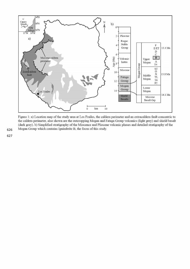
The study area is located in the southwest of the caldera island of Gran Canaria, Spain (Fig. 1a). Initial 138
caldera collapse occurred at 14 Ma, forming the ca. 20 km in diameter Tejeda caldera, and blanketing 139
the island with at least 20 individual ignimbrite flows between 5 m to 40 m thick (Schminke, 2004; 140
Jutzeler et al., 2010; Soden and Shipton, 2013). We focus on one of these ignimbrite units called 141
ignimbrite B (Schmincke, 1998), which was erupted during initial caldera collapse and forms part of 142
the Upper Mogan Formation (Fig. 1b). Ignimbrite B is a densely welded, ash and fiamme rich 143
ignimbrite, blanketing the west and south of the island and ranging in thickness from 10-30 m. 144
Coincident with caldera collapse and ignimbrite eruption was the formation of a system of extra-145
caldera faults (Troll et al., 2002) and fractures (Soden and Shipton, 2013). Faults accommodating 146
extension during caldera collapse formed parallel to the caldera margin (Fig. 1a), inflation of the 147
caldera during subsequent eruptive cycles reactivated these faults and formed an additional set of faults 148
radial to the caldera margin (Branney 1995; Walter and Troll, 2001; Holohan et al, 2012). Joint sets 149
observed by Soden and Shipton (2013), both associated and unassociated with faults, display the same 150
parallel and radial orientations relative to the caldera margin. 151
4. Study site and data collection 152
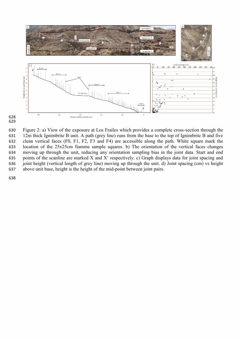
Data were collected from a 12m thick cross-section of ignimbrite B exposed along a valley side at Los 153
Frailes (Fig. 2a). Ignimbrite B is a single cooling unit with a basal vitrophyre marking the lower 154
contact with ignimbrite A and the basal vitrophyre of ignimbrite C marking the top of the unit. Though 155
fiamme rich throughout, the top 2 meters of Ignimbrite B is fiamme poor and ash rich, the long axes of 156
fiamme are sub-parallel to the unit base. Along a path that runs form the base of ignimbrite B to 2 157
meters below the top of the unit, we collected fiamme data from five clean vertical faces that are 158
exposed along road cuts. We collected no fiamme data between the road cuts as rock surfaces are 159
heavily weathered, obscuring the fiamme. Joint data were collected along the entire length of the path, 160
with the exception of one section where the surface was completely scree-covered (Fig. 2a & b). Each 161

road-cut face is labelled F and numbered from 0 to 4, where 0 is at the base of the unit and 4 at the top 162
(Fig.2a, b & c). No faults were observed at, or in the vicinity of the study site. 163
Joint data (spacing, orientation, height, and aperture) were recorded using one scanline starting at the 164
base of the unit (RHS of Fig. 2a & c) and continuing upward along the path to 10.5m above the unit 165
base (LHS of Fig. 2a & c). At the base of ignimbrite B, the scanline was positioned immediately above 166
the basal vitrophyre (face F0, Fig. 2a) and continued along the path at the base of the outcrops. The 167
scanline was parallel to the strike of the outcrop and, due to the gradual slope of the path, sub-168
horizontal. Data from every joint that touched or crossed the scanline was collected. All joints were 169
observed to continue upward from the path, and the majority cut the entire height of the outcrop face, 170
although some terminated within the face. For the total of 106 joints, the location and measured height 171
of each was plotted against distance along the line (Fig. 2c). The use of a continuous scanline ensures 172
the data are not biased by site selection on the best exposed faces, as would potentially be the case for 173
discrete scanlines. Rather, our method provides a complete record from the exposed portions of the 174
joint system along the scanline. Given the lack of horizontal variation in ignimbrite composition and 175
the absence of faults in or near the sample line, we believe that the scanline captures the vertical 176
variation in joint development through this one ignimbrite unit. 177
Joint spacing was recorded as the horizontal distance between all pairs of adjacent joints for which 178
there was full exposure. The outcrop orientation changes along the path (Fig. 2b) and all joint spacing 179
measurements have been corrected for strike using the Terzaghi correction. The mean strike values for 180
the outcrop and the distance along the scanline along which they apply, starting at F0 and moving up 181
along the path, are 075 (0 - 4.5m), 140 (4.5m – 14.5m), 014 (14.5m – 33m), 040 (33m – 52m), 035 182
(65m – 76m), 077 (76m – 84m), 010 (84m – 97m) and 075 (100m – 106m). Joint dip ranges between 183
58° and 90° with a mean of 85°. Joint height was measured from the base of the unit or path to the joint 184
tip or the top of the exposure. Nowhere was both the lower and upper end of a joint observed, thus 185
measurements only constrain the minimum joint length at the exposure and are censored. On Face F0, 186
all joints met the base of the unit, whereas on faces F1-F4 the lower end of the joints were not 187
observed. No joints were observed to continue from ignimbrite B into either ignimbrite A or C, 188
therefore ignimbrite B is considered to be an independently fractured mechanical unit. 189
The fiamme within the layer were sampled using 25x25cm squares drawn on to the vertical road-cut 190
faces, as these provided the best exposure. Since the mechanical controls on joint initiation, 191
propagation and termination were the focus of this study, the sample areas at each face were located 192
where joint(s) were present. An example of a sample square, showing an annotated joint and 193
neighbouring fiamme is shown in Figure 3. The number of sample squares on each face depended on 194
the quality of the exposure, whereas both the fiamme and joints cutting the face, had to be clearly 195

visible. Face 0, 1 and 2 have three sample squares and fiamme on Face 3 were sampled using two 196
squares. Due to the poor quality of the exposure and small number of joints at Face 4, only one sample 197
square was located on the face. The location of each sample square is shown in Figure 2a with white 198
squares. Photographs of the sample areas were digitised, and using Image J freeware, the maximum 199
and minimum axis of each fiamme and number of fiamme were recorded. The calculated fiamme 200
aspect ratios were used to determine the degree of welding and any relative change in welding along a 201
vertical profile through ignimbrite B. Fiamme that were totally or partially enclosed within the area of 202
the sample square were measured in our analysis. 203
5. Field data and analysis 204
5.1 Joint geometry 205
The joints are steeply dipping having a mean dip of 850, and orientated perpendicular to the unit base. 206
Vertical trace length ranges from 2.5 cm to 3.8m (Fig. 2c), although the maximum observed trace 207
length was limited by the tops of the outcrop faces at any sampling location. The majority of joints 208
have apertures of 2-3 mm, and the maximum aperture recorded was 3.7 cm. No observed joints were 209
mineralised. Joints are composed of planar sections that step where the joint intersects fiamme, as no 210
joint surface was exposed, no plumose structures if present were observed. Consequently, we could not 211
determine sites of joint initiation or the propagation paths. 212
Cluster analysis of the joint orientations (Stereonet 9.5, Allmendinger et al., 2012) reveals a well 213
defined NW-SE joint set with an average strike of 127, concentric to the caldera perimeter, and a less 214
well defined NE-SW joint set with an average strike of 046, radial to the caldera margin (Fig. 4). Small 215
populations of other joints have even weaker N-S and ENE-WSW trends. As mentioned previously, 216
caldera collapse formed a system of extra-caldera faults and joints parallel and concentric to the 217
caldera margin. At Los Frailes, the abundant NW-SE joint set is essentially parallel to the caldera 218
margin. While there is greater scatter in the NE-SW joints, the mean orientation is perpendicular to the 219
caldera margin, with a number of joints that are oblique to the margin. 220
We believe that one of two mechanisms could be responsible for joint formation: cooling and layer-221
parallel extension related to caldera collapse. Distinguishing cooling joints from tectonic joints in 222
ignimbrites is difficult in the absence of alteration products such as joint fill or bleached rims, which 223
are attributes associated with cooling joints (Sweetkind et al., 2003). Furthermore, cooling joints can 224
form decades after ignimbrite emplacement as the deposit cools to ambient temperatures (Dunne et al., 225
2003). None of the observed joints in ignimbrite B are mineralised, thus our assessment relies on joint 226
geometrical properties. Several lines of evidence suggest that these joints formed in response to 227
regional tectonic stresses after cooling. First, joint intersection angles and orientations are incompatible 228

with a cooling origin. Rather than the 120˚ that is common for intersecting cooling joints (Goehring 229
and Morris, 2008), the intersection angle between the mean strike of the two sets we observed is 82˚. 230
Furthermore, the angle of intersections between adjacent joints is predominantly less than 50˚ (Fig. 5), 231
as opposed to the expected intersection angles of around 120˚ or 60˚ for cooling joints. Second, many 232
joints exhibit geometrical interactions with fiamme, where joints step across fiamme (Fig. 6a, b & d) 233
and a number of joints terminate against horizontal or steeply dipping joints (Dunne et al., 2003). 234
Hence, the joints interacted with these pre-existing features, rather than following a cooling front. 235
Thirdly, joint spacing increases and correspondingly, joint abundance decreases toward the top of 236
Ignimbrite B (Fig. 2d). This geometric pattern is contrary to the expectation for joints formed in 237
response to thermal contraction, where joint spacing increases toward the layer centre (DeGraf and 238
Aydin, 1993). Lastly, Soden and Shipton (2013) showed that joints in Ignimbrite B on the west coast 239
of Gran Canaria are orientated NS and EW, radial and tangential to the caldera margin, respectively 240
and formed in response to cycles of caldera inflation and collapse. In summary, evidence from analysis 241
of the joint network geometry strongly suggests that the joints are not the result of cooling, but rather 242
related to layer-parallel extension during caldera collapse and/or inflation.. 243
5.2 Joint intensity 244
The scanlines record data obliquely upwards through the unit (Fig. 2c). We use these data to examine 245
variation in joint characteristics from the base to the top of the layer, given the lack of nearby faults or 246
lateral variation in ignimbrite composition to trigger changes in joint system attributes. To assess 247
changes in joint frequency vertically within the unit, we plot the height within the unit against the 248
horizontal spacing for each adjacent pair of joints with full exposure (Fig. 2d). Height is calculated as 249
the height above the ignimbrite base mid-way between the pair of joints. This graph shows joints 250
higher in the unit are more widely spaced and with greater variability in joint spacing, upward in the 251
unit. 252
Joints in Ignimbrite B are layer confined and, given the relationship to the caldera margin, we suggest 253
formed by layer extension during periods of caldera deflation and inflation. As previously stated, 254
layer-confined, opening-mode joints commonly have a positive correlation between median joint 255
spacing and mechanical layer thickness. The fundamental mechanism proposed to explain this 256
relationship is the shear-lag model (Cox, 1952; Hobbs, 1967). Briefly the model involves the layer-257
parallel extension of a competent layer bounded between two less competent layers. Joints form when 258
the tensile stress exceeds the tensile strength of the competent layer, with sequential joints forming 259
midway between existing joints when the tensile stress again exceeds the layer tensile strength. The 260
shear-lag model predicts that continued layer-parallel extension will ultimately result in the fracturing 261
layer becoming joint saturated; at this point no new joints will form regardless of increasing strain (Wu 262

and Pollard, 1995; Bai et al, 2000; Bai and Pollard, 2000b; Dharani et al., 2003). Bai and Pollard 263
(2000) proposed that a joint saturated layer will have a joint density (D) times layer thickness (T) 264
between 0.8 and 1.2. If DT is approximately one, the layer is considered to be joint saturated, DT 265
values >1.2 and <0.8 indicate the layer is over- and under-saturated respectively, and in the case of 266
over-saturation new joints will not form by layer extension alone. 267
Already we have shown that joint spacing varies within the ignimbrite layer. To compare the joint 268
intensity within the ignimbrite layer with studies in sedimentary rocks, we use the relationship between 269
joint density (D) and layer thickness (T) (Ladeira and Price, 1981; Becker and Gross, 1996; 270
Underwood et al., 2003). To estimate DT for the whole ignimbrite layer, we calculated the mean 271
number of joints per meter, D, as 1.02 (Fig. 2d). This value yields a DT value for the whole 12m-thick 272
ignimbrite B layer of 12.24. Indicating that, as a single mechanical layer, Ignimbrite B is highly joint 273
over-saturated, which is contrary to Ladeira and Price (1981), who observed lower than expected joint 274
intensity in thick layers. 275
5.3 Fiamme mechanical properties 276
Although the ignimbrite is densely welded throughout, a number of observations suggest that the 277
fiamme are weaker than the ash matrix. Firstly, the ash matrix is pervasively jointed at the study site, 278
whereas only one fiamme has joints that only occur in the fiamme without entering the adjacent 279
welded ash. Secondly, SEM examination (Fig. 7) shows that the ignimbrite has undergone vapour 280
phase alteration, producing meshworks of interlocking micro-crystals in the ash, thereby reducing 281
porosity and strengthening the matrix (Fig. 7) (McArthur et al., 1998). Conversely, vapour phase 282
alteration created porosity in fiamme, as well as producing discrete acicular crystals lining fiamme in 283
the base of the unit and meshworks (spheurlites) of crystals in fiamme toward the top of the unit (Fig. 284
8). Although the exact timing of the secondary alteration relative to joint formation is uncertain, 285
vapour-phase alteration occurs below the glass transition temperature when deformation changes from 286
ductile to brittle (Giordano et al., 2005), thus the secondary alteration is either prior to or 287
contemporaneous with jointing. The contrast in mechanical properties between the fiamme and ash 288
will tend to promote joint initiation at the weaker fiamme, where a local tangential tensile stress is 289
generated within the stiffer ash matrix (Pollard and Aydin, 1988). 290
5.4 Distribution of fiamme 291
Fiamme sampling squares 25x25cm were placed at heights of 0.25m, 1.5m, 5.5m, 8.5m and 10m 292
above the ignimbrite base for each of faces F0 through to F4, respectively (Fig. 2a). The fiamme 293
density (# fiamme/cm2) for each face is plotted against height above the unit base in figure 8a. A slight 294
drop in fiamme abundance within the ignimbrite between station F1 and F2 is observed (Fig. 8a). The 295
decrease in mean fiamme abundance (Fig. 8a) appears to coincide with the increase in mean joint 296

spacing (Fig. 2d), which we suggest indicates weaker fiamme are localising tensile stress and 297
promoting joint initiation and propagation. 298
5.5 Fiamme shape 299
The welding profile of Ignimbrite B was examined by measuring the aspect ratio of each fiamme 300
within the sample squares, from which the median aspect ratio for each face, as well as for the entire 301
ignimbrite layer, were determined. The median fiamme aspect ratio for Ignimbrite B is 5.5, with values 302
from each sample square ranging from 1.5 to 43 (Fig. 8b), thus Ignimbrite B is a densely welded 303
ignimbrite (Quane and Russell, 2005). As with fiamme abundance, the fiamme aspect ratio decreases 304
between station F1 and F2 (Fig. 8b), including the median, upper and lower quartiles of the aspect ratio 305
distribution. Also, all but two of the measured fiamme with an aspect ratio greater than 20 are in the 306
bottom 2 meters of the unit (Figure 8b). In section 2, we stated that a decrease in fiamme aspect ratio 307
indicates a decrease in the degree of welding, hence welding intensity decreases toward the top of 308
Ignimbrite B. The decrease in fiamme aspect ratio also coincides with the decrease in joint abundance 309
(Fig. 2d). Lower aspect ratio fiamme are less oblate and, in cross-section, fiamme tips have a lower 310
curvature. We suggest that the decrease in tip curvature diminishes the stress concentration tangential 311
to the fiamme, thereby inhibiting joint propagation in the upper portion of Ignimbrite B. 312
5.6 Joint-fiamme interaction 313
From our analysis of the joint and fiamme data, we believe that the shape, material properties and 314
distribution of the fiamme strongly influence joint initiation and propagation within Ignimbrite B. To 315
investigate the potential role that fiamme shape had on joint propagation, we divided the fiamme data 316
into two groups – jointed fiamme (i.e. those where a joint steps across, cross-cuts or terminates at the 317
fiamme) and unjointed fiamme. A plot of these data shows that fiamme with greater aspect ratios are 318
more commonly intersected by a joint (Fig. 8c). The results of a t-test demonstrate that at all 319
stratigraphic positions, a highly significant difference exists between the mean aspect ratio of the 320
jointed and unjointed fiamme, implying that joints intersect high-aspect ratio fiamme preferentially to 321
lower aspect-ratio fiamme (Table 1). 322
Insert Table 1 323
Aspect ratio is a measure of fiamme compaction and hence potentially correlates with their mechanical 324
properties. We must consider, however, the possibility that high aspect-ratio fiamme merely have a 325
greater lateral extent, and consequently propagating joints have a greater probability of intersecting 326
them. Data to discount this possibility are shown in Table 2, where the median lengths of jointed and 327
unjointed fiamme differ by less than a millimetre but jointed fiamme aspect ratio is on average 40% 328
greater than that of the unjointed fiamme. Hence, the observed preferential joint interaction with high 329
aspect ratio fiamme is not due to an increase in their average lateral extent. Thus, the presence of 330
fiamme with greater aspect ratios was an important contributor to joint initiation and propagation, by 331
localising stress at fiamme tips. To further test this hypothesis, we analysed the different joint-fiamme 332
interaction geometries, and positions along the length of fiamme where the joint intersected. (Table 3, 333
Figure 6). 334
Insert Table 2 335
Four types of joint-fiamme interaction are observed (Fig.6): unlinked stepping joints and linked 336
stepping joints that step across fiamme (Fig. 6a & b), single joints that pass straight through fiamme 337
(Fig. 6c), and single joint tips located at fiamme, i.e. joint initiation or termination (Fig. 6b). All joints 338
are orthogonal to the fiamme long axis. Importantly, as joint surfaces are unexposed and initiation 339
points and propagation paths unknown, joint geometries reflect joint interactions with fiamme. 340
Consequently, the observed joint tips may be a 2D section through a joint tip-line rather than the actual 341
joint initiation or termination point. The location of the joints along the fiamme long axis was defined 342
as either occurring at the fiamme tip or non-tip, where we defined the tip area as the distance from the 343
fiamme tip to one quarter way along the length of the fiamme. 344
The results of the joint-fiamme interation analysis are shown in Table 3. For all faces, greater than 345
50% of all joint types intersect the tip area of the fiamme - F0 57.7%; F1 55.5%; F2 56%; F3 60.2%; 346
F4 76%. This supports our proposition that the high curvature fiamme tips localise tensile stress 347
resulting in joint initiation and propagation. The remainder of the joints intersect the central portion of 348
the fiamme, and hence, we infer that tangential stress resulting from a weak inclusion imbedded in a 349
stronger matrix also has a role to play in joint propagation. 350
The joint geometries also reflect differences in material properties between the fiamme and ash matrix. 351
The geometry of a joint is affected by the mechanical properties of the material through which it 352
propagates. Work examining the propagation of joints in alternating shale and siltstone sequences 353
(Hegelson and Aydin, 1991) demonstrates how the stress ahead of a joint tip is transmitted between 354
stiff layers (higher modulus) across a weaker (lower modulus) interlayer. As the joint approaches the 355
weaker interlayer, the transfer of the fracture tip stress across the layer produces two stress maxima in 356
the unjointed stiff layer, which result in the joint stepping as it crosses the weaker layer. However, 357
there is a critical weak layer thickness that impedes joint propagation, causing joints to terminate at the 358
weak layer (Rijken and Cooke, 2001). When layers have similar Young’s moduli the joint propagates 359
straight through all layers. 360
In general, models of joint interaction with layer interfaces show joints often terminate at weak 361
interfaces (Renshaw and Pollard, 1995; Cooke et al., 2006), propagate straight through strong 362

interfaces, and step at interfaces of moderate strength (Cooke et al., 2006). Hence, the observed joint 363
geometries reflect the variation in the relative strength between the fiamme and ash matrix, as well as 364
the different fiamme-ash interface mechanical strengths. Between 58% and 84% of joints cut straight 365
through fiamme (Table 3), suggesting that either the fiamme and matrix are of the similar strength, or 366
there is a strong fiamme-matrix interface. The greater proportion of these straight joints cut the fiamme 367
tip, indicating a difference in material property between the fiamme and ash, as is shown by our SEM 368
analysis. Further, the fiamme in this group have high aspect ratios indicating a strong degree of 369
compaction and welding. Hence, the geometry is likely a result of a strong fiamme-ash interface. The 370
next most frequently observed joint type are joint tips located at fiamme, however as we have stated, 371
these may not be true joint tips and without seeing the joint surface we cannot say if these are joint 372
initiation or termination points. It should be noted, however, that the lower tip of a joint is never 373
observed (they all propagate down to the path or layer base). Hence, it seems likely that many 374
observations of joint tips are terminations of upwardly propagating joints. In which case, given that the 375
mean fiamme aspect ratios of this group do not differ greatly to fiamme in the other two groups, these 376
fiamme must be much weaker than the ash matrix. As such, the weak fiamme are acting to terminate 377
joints and hence reduce the joint intensity in the upper part of the ignimbrite. Stepping joints make up 378
between 7% and 15% of all joint types and are approximately evenly split between joints intersecting 379
fiamme at tips and non-tips. Joints stepping across fiamme indicate the fiamme are weaker than the 380
matrix. We divided stepping joints into joints that are linked across fiamme via a horizontal section 381
and those that are not linked (Table 3, Fig. 6b). The mean aspect ratio of fiamme in the unlinked 382
stepping group is generally smaller than for fiamme cut by straight joints. Smaller aspect ratio 383
indicates less compaction and welding and possibly a fiamme-ash interface of moderate strength. 384
Fiamme in the linked stepping joint group have mean aspect ratios less than or similar to fiamme cut 385
by straight joints. The latter case may reflect fiamme which having undergone vapour phase alteration 386
and are weaker than the matrix. 387
Insert Table 3 388
The observations summarised in Table 3 support the proposition that fiamme perturbed the stress field 389
during joint formation. The extent to which the stress field was perturbed, is a function of fiamme 390
shape and the contrast in material properties between the fiamme and the surrounding matrix. For all 391
joint geometry types, the greater proportion of joints interact with fiamme tips, thus the high curvature 392
of the fiamme tips localise stress and are sites of joint initiation or propagation. The termination or 393
stepping of joints is a result of the contrast in mechanical properties between fiamme and ash and the 394
strength of the fiamme-ash interface. Given the competing effects of fiamme distribution, shape and 395
material properties that influence the joint network, it is unlikely that small changes in any one 396

parameter can be directly correlated to changes in joint intensity. Rather changes across all fiamme 397
characteristics act to produce a greater change in joint intensity. 398
6. Model for joint network development 399
Based on our analysis, we believe that the control on joint intensity within Ignimbrite B is the spatial 400
distribution, geometry and mechanical properties of the fiamme in the unit rather than the thickness of 401
the unit. Joint intensity is greatest where the fiamme aspect ratio is greatest at the unit base. We 402
propose this relationship is due to larger stress concentrations at the tips of the more elongate fiamme, 403
which are weaker than the surrounding ash matrix, and to stress tangential to the weaker fiamme 404
embedded in the stiffer matrix; providing favourable sites for joint nucleation (Fig. 9). If a joint 405
approaches a densely welded fiamme, propagation straight through or with a step across the fiamme is 406
likely, depending on the fiamme-ash mechanical contrast and the fiamme-ash interface strength. If a 407
joint encounters a less welded, low aspect ratio fiamme it is more likely to terminate. We propose that 408
joints propagate upward, and as they propagate upward they, encounter progressively fewer and less 409
welded fiamme, thereby inhibiting joint propagation. This proposed model of joint initiation and 410
growth (Fig. 9) explains the observed spatial distribution of joints throughout ignimbrite B, as well as 411
the apparent decrease in joint intensity with increasing elevation within the unit. 412
Our analysis shows that the mechanical heterogeneity within Ignimbrite B plays a significant role in 413
controlling joint geometry and location. The spatial distribution, mechanical and geometric properties 414
of fiamme influence joint initiation, propagation and termination, which in turn control the abundance 415
of joints throughout the unit. These results suggest that greater attention should be paid to the spatial 416
heterogeneity of rock strength when developing predictive models for fracture networks. The 417
properties and distribution of flaws like fiamme may exert controls on fracture network properties that 418
are equal to or greater than the well-known influences of variables such as layer thickness and 419
interfacial shear strength.. 420
Conclusions 421
We study joint frequency and orientation throughout the full thickness of an ignimbite located on the 422
island of Gran Canaria, Spain. Our observations show that joint spacing varies vertically within the 423
unit, in tandem with subtle variations in the geometrical and mechanical properties of fiamme within 424
the ash matrix. Propagating joints interact with fiamme and we propose that this interaction is 425
responsible for the observed joint distribution and joint geometries. We propose a model whereby joint 426
initiation, propagation and termination are governed by vertical variations in the geometrical and 427
mechanical properties of the fiamme. We suggest that joints initiate near the base of the unit where the 428
fiamme are more densely welded, due both to their high aspect ratio that causes larger stress 429

concentrations at their tips, and their lower strength, which contrasts with the stronger surrounding ash 430
matrix. Once initiated, we propose that joints propagate predominantly upwards through the unit. As 431
they encounter fiamme, they either step across them or terminate. Joints are more likely to terminate 432
on fiamme with low aspect ratios, which are more common in the upper half of the ignimbrite unit. As 433
a result joint intensity is very high at the base of the unit and decreases with increasing elevation. 434
Our research shows that in a mechanically heterogeneous lithology (i.e. with inclusions, lenses, clasts 435
etc.) with weakly defined layering, joint intensity can be governed by the number and spatial 436
distribution of heterogeneities with particular geometrical and mechanical properties. Consequently, 437
joint spacing and location in siliciclastic or volcaniclastic lithologies at depth, may not be well 438
described by models based only on the role of layer thickness. More accurate predictions may require 439
characterisation of the composition and material properties within each layer. 440
441
References 442
Allmendinger, R.W., Cardozo, N., Fisher, D.M., 2011. Structural Geology Algorithms: Vectors and 443
Tensors. Cambridge University Press. ISBN: 9781107401389. 444
Bai, T., Pollard, D.D., 2000. Fracture spacing in layered rocks: a new explanation based on the stress 445
transition: Journal of Structural Geology, v. 22, p. 43-57. 446
Bai, T., Pollard, D.P., 2000. Closely spaced fractures in layered rocks: initiation mechanism and 447
propagation kinematics. Journal of Structural Geology, v. 22, p. 1409-1425. 448
Becker, A., Gross, M.R., 1996. Mechanism for joint saturation in mechanically layered rocks: an 449 example from southern Israel: Tectonophysics, v. 257, p. 223-237. 450
Branney, M.J., 1995. Downsag and extension at calderas: new perspectives on collapse geometries 451 from ice-melt, mining, and volcanic subsidence: Bulletin of Volcanology, v. 57, p. 303-318. 452
Brown, D.J., 2007. A guide to the use of volcaniclastic nomenclature in engineering investigations. 453 Quaterly Journal of Engineering Geology and Hydrogeology 40, 105-112. 454
Bull, K.F., McPhie, J., 2007. Fiamme textures in volcanic successions: flaming issues of definition and 455
interpretation. Journal of Volcanology and Geothermal Research 164, 205-216. 456
Cacas, M.C., Daniel, J.M., Letouzey, J., 2001. Nested geological modelling of naturally fractured 457 reservoirs. Petroleum Geoscience 7, 543-552. 458
Cooke, M. L., J. A. Simo, C. A. Underwood, and P. Rijken, 2006, Mechanical stratigraphic controls on 459 fracture patterns within carbonates and implications for groundwater flow: Sedimentary Geology, v. 460 184, no. 3–4, p. 225–239. 461
Cox, H.L., 1952. The elasticity and strength of paper and other fibrous materials. British Journal of 462
Aplied Physics 3, 72-79. 463
DeGraff, J.M., Aydin, A. 1987. Surface morphology of columnar joints and its significance to 464 mechanics and direction of joint growth. Geological Society of America 99, 605-617. 465
Dharani, L.R., Wei, J., Ji, F.S., Zhao, J.H., 2003. Saturation of transverse cracking with delamination 466 in polymer cross-ply composite laminates. International Journal of Damage Mechanics 12, 89–113 467

Dunne, W.M., Ferrill, D.A., Crider, J.G., Hill, B., La Femina, P., Waiting, D., Morris, A.P., Fedors, R., 468 2003. Orthogonal jointing during coeval igneous degassing and normal faulting, Yucca Mountain, 469
Nevada. Geological Society of America Bulletin 115, 1492-1509. 470
Fischer, M.P., Polansky, A., 2006. Influence of flaws on joint spacing and saturation: Results of one-471 dimensional mechanical modelling. Journal of Geophysical Research, 111. B07403, doi: 472 10.10292005JB004115. 473
Fox, D. B., Sutter, D., Beckers, K. F., Lukawski, M. Z., Koch, D., Anderson, B. J., Tester, J. W., 2013. 474 Sustainable heat farming: Modeling extraction and recovery in discretely fractured geothermal 475 reservoirs.Geothermics 46, 42-54. 476
Giordano, D., Nichols, A.R.L., and Dingwell, D.B., 2005. Glass transition temperatures of natural 477 hydrous melts: a relationship with shear viscosity and implications for the welding process. Journal of 478 Volcanology and Geothermal Research 142, 105-118. 479
Goehring, L., Morris, S. W., 2008. Scaliing of columnar joints in basalt. Journal of Geophysical 480 Research B113, B10203. 481
Gross, M.R., 1993. The origin and spacing of cross joints: examples from the Monterey Formation, 482 Santa Barbara Coastline, California: Journal of Structural Geology 15, 737-751. 483
Gross, M.R., Engelder, T., 1995. Strain accommodated by brittle failure in adjacent units of the 484
Monterey Formation, U.S.A.: scale effects and evidence for uniform displacement boundary 485
conditions: Journal of Structural Geology 17, 1303-1318. 486
Grunder, A., Russell, J.K., 2005. Welding processes in volcanology: insights from field, experimental, 487 and modeling studies: Journal of Volcanology and Geothermal Research, Welding Processes in 488 Volcanology 142, 1-9. 489
Helgeson, D.E., Aydin, A., 1991. Characteristics of joint propagation across layer interfaces in 490 sedimentary rocks. Journal of Structural Geology 13, 897– 911. 491
Henry, C.D., Wolff, J.A., 1992. Distinguishing strongly rheomorphic tuffs from extensive silicic lavas. 492
Bulletin of Volcanology 54, 171-186. 493
Hobbs, D.W., 1967. The formation of tension joints in sedimentary rocks: an explanation. Geological 494 Magazine, v. 104, p. 550-556. 495
Hoek, E., Brown, E. T., 1997. Practical estimates of rock mass strength. Int. J. Rock. Min. Sci. 34, 496 1165-1186. 497
Hofmann, H., Babadagli, T., Zimmermann, G., 2014. Hot water generation for oil sands processing 498
from enhanced geothermal systems: Process simulation for different hydraulic scenarios. Applied 499 Energy 113, 524-547. 500
Holohan, E., Schöpfer, M. P. J., Walsh, J. J., 2011. Mechanical and geometric controls on the 501 structural evolution of pit crater and caldera subsidence. Journal of Geophysical Research, 116, B07 502
Huang, Q., Angelier, J., 1989. Fracture spacing and its relation to bed thickness. Geological Magazine, 503 104, 355-362. 504
Ji, S., Saruwatari, K., 1998. A revised model for the relationship between joint spacing and layer 505 thickness: Journal of Structural Geology, 20, 1495-1508. 506
Jimenez-Martinez, J., Longuevergne, L., Borgne, T., Davy, P., Russian, A., Bour, O., 2013. Temporal 507
and spatial scaling of hydraulic response to recharge in fractures aquifers: Insights from a frequency 508
domain analysis. Water Resources Research 49, 3007-3023. 509

Jutzeler, M., Schmincke, H-U., Sumita, M., 2010. The incrementally zoned Miocene Ayagaures 510 ignimbrite (Gran Canaria, Canary Islands). Journal of Volcanology and Geothermal Research 196, 1-511
19. 512
Kobberger, G., Schmincke, H.-U., 1999. Deposition of rheomorphic ignimbrite D (Mogan Formation), 513 Gran Canaria, Canary Islands, Spain: Bulletin of Volcanology, 60, 465-485. 514
Koning, T., 2003. Oil and gas production from basement reservoirs: Examples from Indonesia, USA 515
and Venezuela. In: Petford N., McCaffrey K.J.W. (eds) Hydrocarbons in Crystalline 516 Rocks. Geological Society, London, Special Publications 214, 83–92. 517
Ladeira, F. L., N. J. Price, 1981. Relationship between fracture spacing and bed thickness. Journal of 518
Structural Geology 3, 179–183. 519
Larsen, B., Gudmundsson, A., Grunnaleite, I., Saelen, G., Talbot, M.R., and Buckley, S.J., 2010. 520 Effects of sedimentary interfaces on fracture pattern, linkage, and cluster formation in peritidal 521
carbonate rocks. Marine and Petroleum Geology 27, 1531 – 1550. 522
McArthur, A.N., Cas, R.A.F., and Orton, G.J., 1998. Distribution and significance of crystalline, 523
perlitic and vesicular textures in the Ordovician Garth Tuff (Wales). Bulletin of Volcanology 60, 260-524 285. 525
McConaughy, D.T., Engelder, T., 2001. Joint initiation in bedded clastic rocks. Journal of Structural 526
Geology 23, 203-221. 527
Miller, T. F., Riehle, J. R., 1994. A users manual for Ashpac: a program for predicting cooling, 528
outgassing and compaction of pyroclastic deposits. Tech. Rep. TR94-14, Applied Research Lab., Penn. 529 State Univ., State College. 530
Moon, V. G., 1993. Geotechnical characteristics of ignimbrite: A soft pyroclastic rock type, Eng. 531 Geol., v. 35, p. 33–45. 532
Neuman, S. P., 2005. Trends, prospects and challenges in quantifying flow and transport through 533 fractured rocks. Hydrogeology journal 13, 124-147. 534
Narr, W., Suppe, J., 1991. Joint spacing in sedimentary rocks: Journal of Structural Geology 13, 1037-535
1048. 536
Pollard, D.D., Aydin, A., 1988. Progress in understanding jointing over the past century: Geological 537 Society of America Bulletin 100, 1181-1204. 538
Quane, S.L., Russell, J.K., 2003. Ranking welding intensity in pyroclastic deposits. Bulletin of 539 Volcanology 67, 129-143. 540
Ragan, D.M., Sheridan, M.F., 1972. Compaction of the Bishop tuff, California. Geological Society of 541 America Bulletin 83, 95-106. 542
Renshaw, C.E., Pollard, D.D., 1994. Numerical simulation of fracture set formation: A fracture 543 mechanics model consistent with experimental observations: Journal of Geophysical Research 99, 544 9359-9372. 545
Riehle, J. R., 1973. Calculated compaction profiles of Rhyolitic ash-flow tuffs. Geological Society of 546 America Bulletin 84, 2193-2216. 547
Riehle, J. R., Miller, T. F., Paquereau-Lebti, P., 2010. Compaction profiles of ash-flow tuffs: Modeling 548 versus reality. Journal of Volcanology and Geothermal Research 195, 106-120. 549
Rijken, P., Cooke, M. L., 2001. Role of shale thickness on vertical connectivity of fractures: 550 application of crack-bridging theory to the Austin Chalk, Texas. Tectonophysics 337, 117-133. 551

Ross, C.S., Smith, R.L. 1961. Ash-flow tuffs; their origin, geologic relations and identification. U.S. 552 geol. Survey Prof. Paper 366, 1-77 553
Schmincke, H.U., 1998. Geological Field Guide to Gran Canaria. Pluto Press, Kiel. 554
Schultz, R.A., Li, Q., 1995. Uniaxial strength testing of non-welded Calico Hills tuff, Yucca Mountain, 555 Nevada: Engineering Geology, v. 40, p. 287-299. 556
Sewell, R.J., Tang, D. L. K., Diarmad, S., and Campbell, D. G., 2012. Volcanic-plutonic connections 557 in a tilted nested caldera complex in Hong Kong. Geochem. Geophys. Geosyst. 13, Q01006. 558
Smith, J.V., Yamauchi, S., Miyake, Y., 1994. Coaxial progressive deformation textures in extrusive 559
and shallow intrusive rocks, southwest Japan. Journal of Structural Geology 16, 315-322. 560
Soden, A. M., Shipton, Z. K., 2013. Dilational fault zone architecture in a welded ignimbrite: The 561 importance of mechanical stratigraphy. Journal of Structural Geology 51, 156-166. 562
Troll, V., Walter, T., Schmincke, H.U., 2002. Cyclic caldera collapse: Piston or piecemeal subsidence? 563
Field and experimental evidence. Geology 30, 135-138. 564
Tuckwell, G.W., Lonergan, W.L., Jolly, R.H.J., 2003. The control of stress histroy and flaw 565 distribution on the evolution of polygonal fracture networks. Journal of Structural Geology 25, 1241 – 566
1250. 567
Underwood, C.A., Cooke, M.L., Simo, J.A., Muldoon, M.A., 2003. Stratigraphic controls on vertical 568
fracture patterns in Silurain dolomite, northeastern Wisconsin. AAPG Bulletin 87, 121-142. 569
Walter, T.R., Troll, V.R., 2001. Formation of caldera periphery faults: an experimental Study. Bulletin 570 of Volcanology 63, 191-203. 571
Weinberger, R., 2001a. Joint nucleation in layered rocks with non-uniform distribution of Cavities. 572
Journal of Structural Geology 23, 1241-1254. 573
Weinberger, R., 2001b. Evolution of polygonal patterns in stratified mud during dessication: The role 574 of flaw distribution and layer boundaries. Geological Society of America Bulletin 113, 20 – 31. 575
Wilson, J.E., Goodwin, L.B., Lewis, C.J., 2003. Deformation bands in nonwelded ignimbrites: 576
petrophysical controls on fault-zone deformation and evidence of preferential fluid flow. Geology 31, 577 837-840. 578
Wu, H., Pollard, D., 1995. An experimental study of the relationship between joint spacing and layer 579
thickness. Journal of Structural Geology 17, 887-905. 580
581
Figure Captions 582
Figure 1: a) Location map of the study area at Los Frailes, the caldera perimeter and an extracaldera 583 fault concentric to the caldera perimeter, also shown are the outcropping Mogan and Fataga Group 584 volcanics (light grey) and shield basalt (dark grey). b) Simplified stratigraphy of the Miocence and 585 Pliocene and volcanic phases and detailed stratigraphy of the Mogan Group which contains Ignimbrite 586
B, the focus of this study. 587
Figure 2: a) View of the exposure at Los Frailes which provides a complete cross-section through the 588
12m thick Ignimbrite B unit. A path (grey line) runs from the base to the top of Ignimbrite B and five 589 clean vertical faces (F0, F1, F2, F3 and F4) are accessible along the path. White square mark the 590 location of the 25x25cm fiamme sample squares. b) The orientation of the vertical faces changes 591
moving up through the unit, reducing any orientation sampling bias in the joint data. Start and end 592 points of the scanline are marked X and X’ respectively. c) Graph displays data for joint spacing and 593

joint height (vertical length of grey line) moving up through the unit. d) Joint spacing (cm) vs height 594 above unit base, height is the height of the mid-point between joint pairs. 595
Figure 3: Example of 25x25cm square from F1 enclosing a joint. Fiamme long axes are sub-horizontal, 596
some fiamme are highlighted in white. 597
Figure 4: Stereonet data plotted for all joints measure along the scanline (n=106). Great circles are for 598 mean strike of NW-SE and NE-SW joint sets. Grey great circle is approximate caldera margin 599
orientation relative to Los Frailes study site. 600
Figure 5: Angle of intersections between joints, and the frequency with which intersection angles 601 occur. 602
Figure 6: Examples of the interaction between fiamme and joints from faces (F) at different heights in 603 the ignimbrite. a & b) On intersecting high aspect ratio fiamme, joints step across the fiamme (ringed 604 in red) forming composite joints composed of multiple segments. c) Where fiamme are less compacted 605
joints pass through the fiamme tips. d) Stepping of a joint along multiple fiamme gives a curved 606 geometry to the joint. 607
Figure 7: Fiamme (selection outlined in red) and ash matrix a) 1m and b) 6m above the ignimbrite 608 base. Fiamme in the base of the unit are compacted and elongate. Secondary alteration processes have 609 devitrified the glassy fiamme and formed acicular crystals in fiamme at the base (c) and spherulites in 610
fiamme in the upper section of the unit (d), as well as crystal meshworks within the matrix (e). The 611 meshworks reduce porosity in the ash matrix. f) Even at the micron level fiamme influence joint 612 geometry causing a joint to step across fiamme. 613
Figure 8: Plots show for each face (F) number of fiamme per square centimetre (a) and aspect ratio for 614
all fiamme sampled within each sample square (b) and fiamme divided into jointed (JF) and unjointed 615
(UNJF) fiamme (c). Sample size at each face for JF and UNJF respectively are F0 n=380 & 220; F1 616 n=311 & 232; F2 n=219 & 451; F3 n=151 & 118; F4 n=66 & 42. Note: Box plots in (c) are vertically 617 offset for visual clarity but fiamme were sampled from the same squares on the outcrop, JF data are 618
plotted at the actual sample heights. 619
Figure 9: Our model demonstrates how mechanical heterogeneities can have a significant impact on 620 joint density within a layer, and that predictions of joint density based on layer thickness will differ 621
greatly from the density and distribution of joints formed in a mechanically heterogeneous layer. 622 Within the layer mechanical heterogeneities can i) localise tensile stress and initiate joints and ii) act as 623 discontinuous mechanical sub-layers promoting or inhibiting joint propagation and influencing joint 624
geometry. 625
626
627
628 629
Figure 2: a) View of the exposure at Los Frailes which provides a complete cross-section through the 630 12m thick Ignimbrite B unit. A path (grey line) runs from the base to the top of Ignimbrite B and five 631 clean vertical faces (F0, F1, F2, F3 and F4) are accessible along the path. White square mark the 632
location of the 25x25cm fiamme sample squares. b) The orientation of the vertical faces changes 633 moving up through the unit, reducing any orientation sampling bias in the joint data. Start and end 634 points of the scanline are marked X and X’ respectively. c) Graph displays data for joint spacing and 635
joint height (vertical length of grey line) moving up through the unit. d) Joint spacing (cm) vs height 636
above unit base, height is the height of the mid-point between joint pairs. 637
638

639 640
Figure 3: Example of 25x25cm square from F1 enclosing a joint. Fiamme long axes are sub-horizontal, 641
some fiamme are highlighted in white. 642
643 644

645 646
Figure 4: Stereonet data plotted for all joints measure along the scanline (n=106). Great circles are for 647 mean strike of NW-SE and NE-SW joint sets. Grey great circle is approximate caldera margin 648
orientation relative to Los Frailes study site. 649
650 651

652
Figure 5: Angle of intersections between joints, and the frequency with which intersection angles 653
occur. 654
655

656
Figure 6: Examples of the interaction between fiamme and joints from faces (F) at different heights in 657 the ignimbrite. a & b) On intersecting high aspect ratio fiamme, joints step across the fiamme (ringed 658
in red) forming composite joints composed of multiple segments. c) Where fiamme are less compacted 659 joints pass through the fiamme tips. d) Stepping of a joint along multiple fiamme gives a curved 660
geometry to the joint. 661
662

663
Figure 7: Fiamme (selection outlined in red) and ash matrix a) 1m and b) 6m above the ignimbrite 664 base. Fiamme in the base of the unit are compacted and elongate. Secondary alteration processes have 665 devitrified the glassy fiamme and formed acicular crystals in fiamme at the base (c) and spherulites in 666 fiamme in the upper section of the unit (d), as well as crystal meshworks within the matrix (e). The 667 meshworks reduce porosity in the ash matrix. f) Even at the micron level fiamme influence joint 668
geometry causing a joint to step across fiamme. 669

670
671
Figure 8: Plots show for each face (F) number of fiamme per square centimetre (a) and aspect ratio for 672 all fiamme sampled within each sample square (b) and fiamme divided into jointed (JF) and unjointed 673 (UNJF) fiamme (c). Sample size at each face for JF and UNJF respectively are F0 n=380 & 220; F1 674
n=311 & 232; F2 n=219 & 451; F3 n=151 & 118; F4 n=66 & 42. Note: Box plots in (c) are vertically 675 offset for visual clarity but fiamme were sampled from the same squares on the outcrop, JF data are 676 plotted at the actual sample heights. 677
678

679
Figure 9: Our model demonstrates how mechanical heterogeneities can have a significant impact on 680 joint density within a layer, and that predictions of joint density based on layer thickness will differ 681 greatly from the density and distribution of joints formed in a mechanically heterogeneous layer. 682
Within the layer mechanical heterogeneities can i) localise tensile stress and initiate joints and ii) act as 683 discontinuous mechanical sub-layers promoting or inhibiting joint propagation and influencing joint 684 geometry. 685