Embed Size (px)
Citation preview
Impact of Process
Control in Pb-Free to
SnPb Reballing
Techniques
Part 1: Control of Thermal Exposure
Joelle Arnold
DfR Solutions
SMTA ISCR 2014
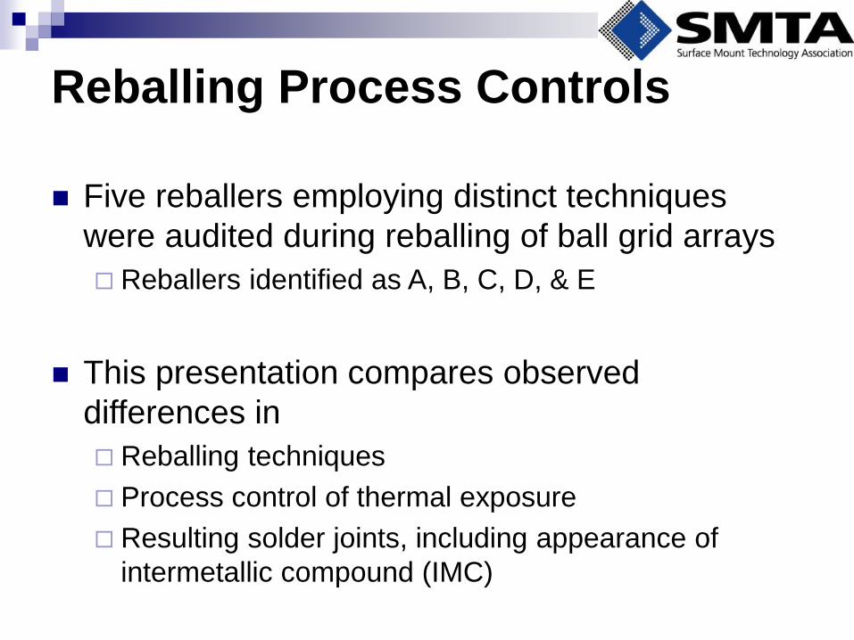
Reballing Process Controls
Five reballers employing distinct techniques
were audited during reballing of ball grid arrays
Reballers identified as A, B, C, D, & E
This presentation compares observed
differences in
Reballing techniques
Process control of thermal exposure
Resulting solder joints, including appearance of
intermetallic compound (IMC)
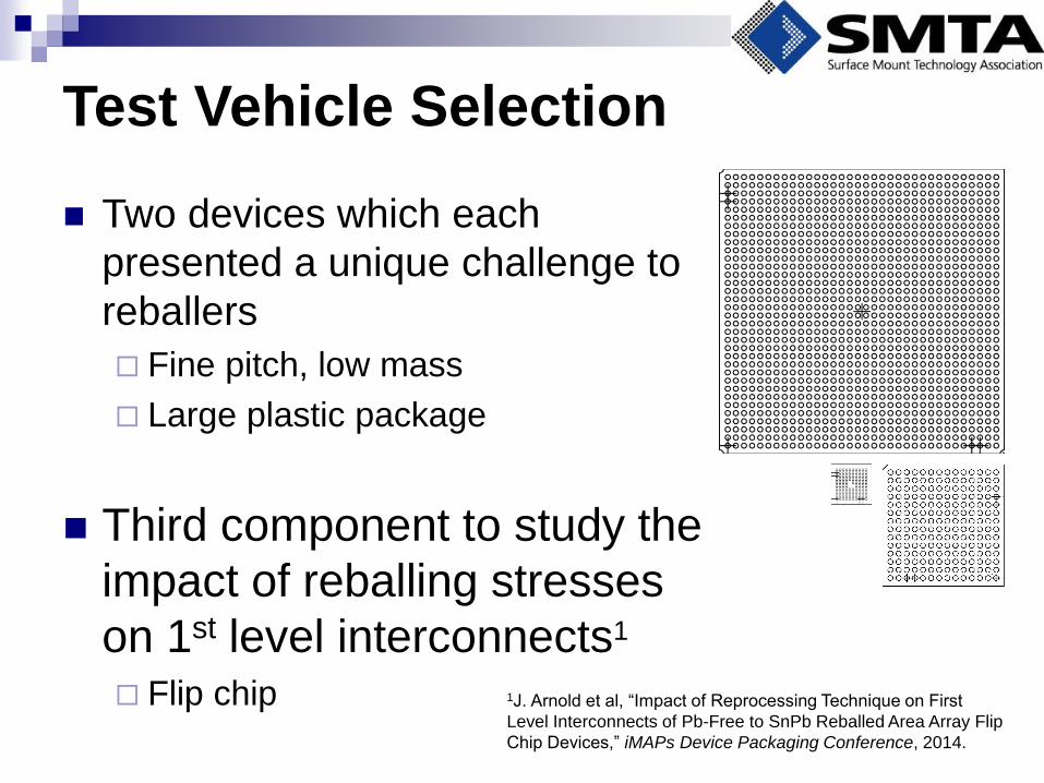
Test Vehicle Selection
Two devices which each
presented a unique challenge to
reballers
Fine pitch, low mass
Large plastic package
Third component to study the
impact of reballing stresses
on 1st level interconnects1
Flip chip
1J. Arnold et al, “Impact of Reprocessing Technique on First
Level Interconnects of Pb-Free to SnPb Reballed Area Array Flip
Chip Devices,” iMAPs Device Packaging Conference, 2014.
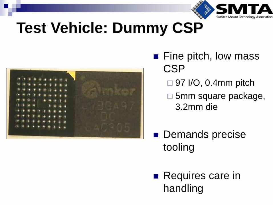
Test Vehicle: Dummy CSP
Fine pitch, low mass
CSP
97 I/O, 0.4mm pitch
5mm square package,
3.2mm die
Demands precise
tooling
Requires care in
handling
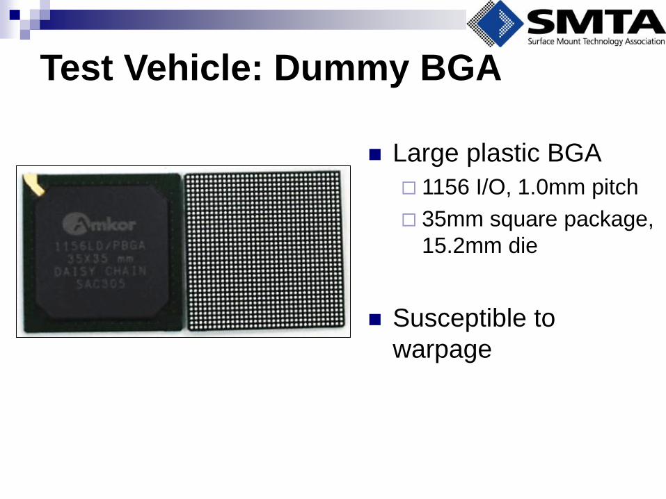
Test Vehicle: Dummy BGA
Large plastic BGA
1156 I/O, 1.0mm pitch
35mm square package,
15.2mm die
Susceptible to
warpage
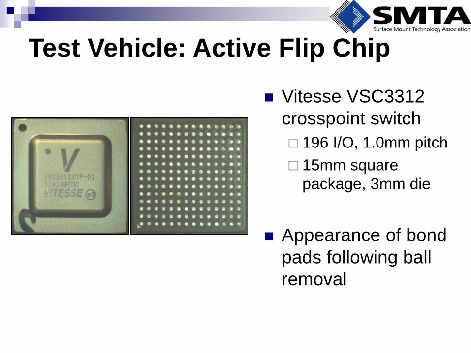
Test Vehicle: Active Flip Chip
Vitesse VSC3312
crosspoint switch
196 I/O, 1.0mm pitch
15mm square
package, 3mm die
Appearance of bond
pads following ball
removal
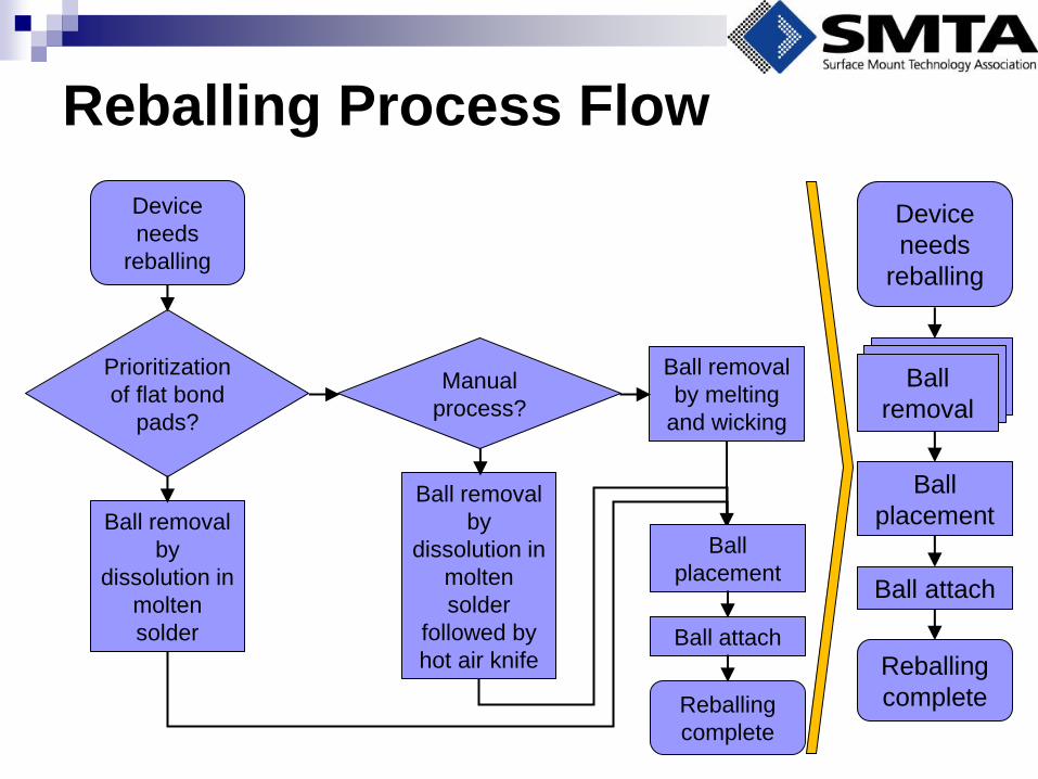
Reballing Process Flow
Device
needs
reballing
Ball removal
by
dissolution in
molten
solder
Ball removal
by
dissolution in
molten
solder
followed by
hot air knife
Ball removal
by melting
and wicking
Manual
process?
Prioritization
of flat bond
pads?
Ball
placement
Ball attach
Reballing
complete
Device
needs
reballing
Ball
placement
Ball attach
Reballing
complete
Ball
removal Ball
removal Ball
removal
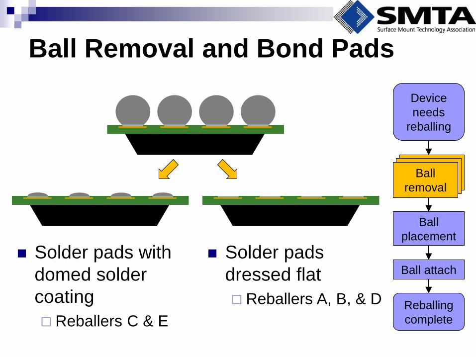
Ball Removal and Bond Pads
Device
needs
reballing
Ball
placement
Ball attach
Reballing
complete
Ball
removal Ball
removal Ball
removal
Solder pads
dressed flat
Reballers A, B, & D
Solder pads with
domed solder
coating
Reballers C & E
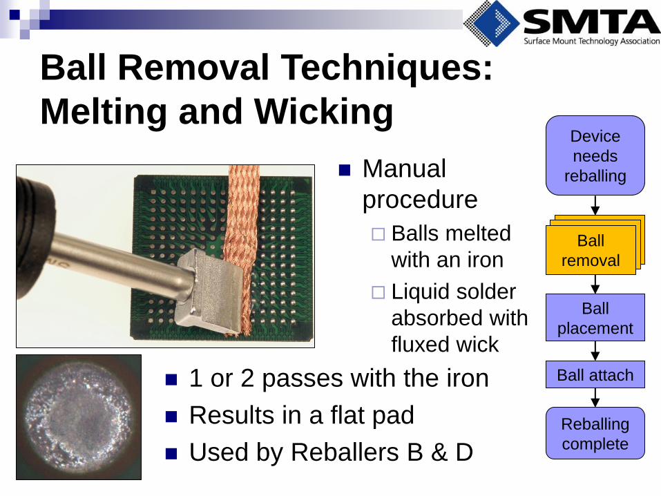
Ball Removal Techniques:
Melting and Wicking
Manual
procedure
Balls melted
with an iron
Liquid solder
absorbed with
fluxed wick
Device
needs
reballing
Ball
placement
Ball attach
Reballing
complete
Ball
removal Ball
removal Ball
removal
1 or 2 passes with the iron
Results in a flat pad
Used by Reballers B & D
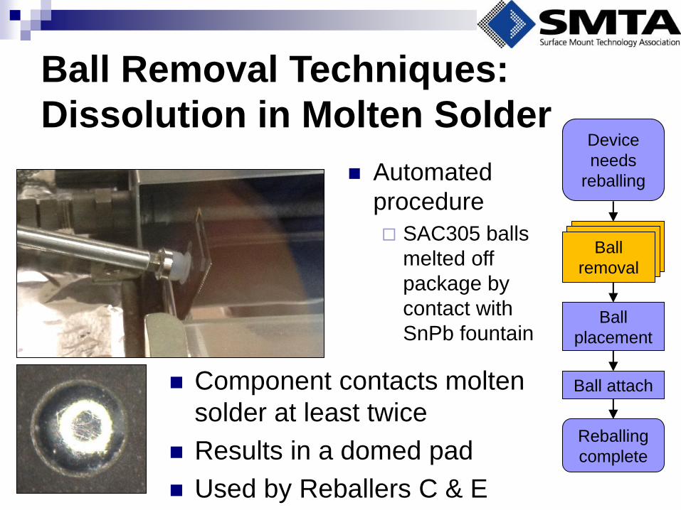
Ball Removal Techniques:
Dissolution in Molten Solder
Automated
procedure
SAC305 balls
melted off
package by
contact with
SnPb fountain
Device
needs
reballing
Ball
placement
Ball attach
Reballing
complete
Ball
removal Ball
removal Ball
removal
Component contacts molten
solder at least twice
Results in a domed pad
Used by Reballers C & E
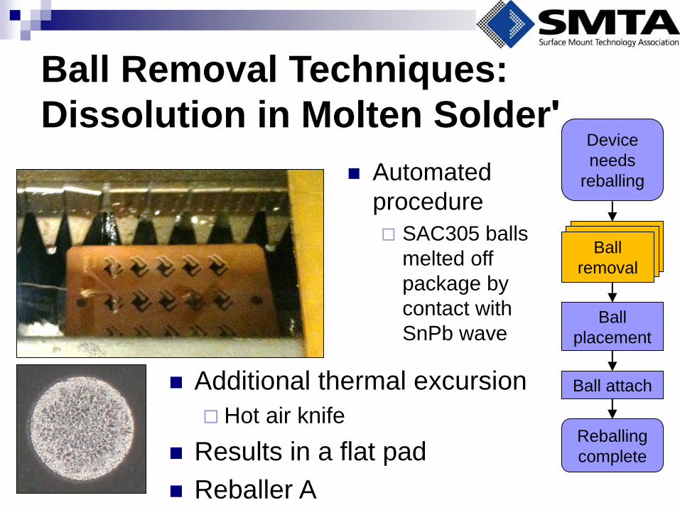
Ball Removal Techniques:
Dissolution in Molten Solderʹ
Automated
procedure
SAC305 balls
melted off
package by
contact with
SnPb wave
Device
needs
reballing
Ball
placement
Ball attach
Reballing
complete
Ball
removal Ball
removal Ball
removal
Additional thermal excursion
Hot air knife
Results in a flat pad
Reballer A
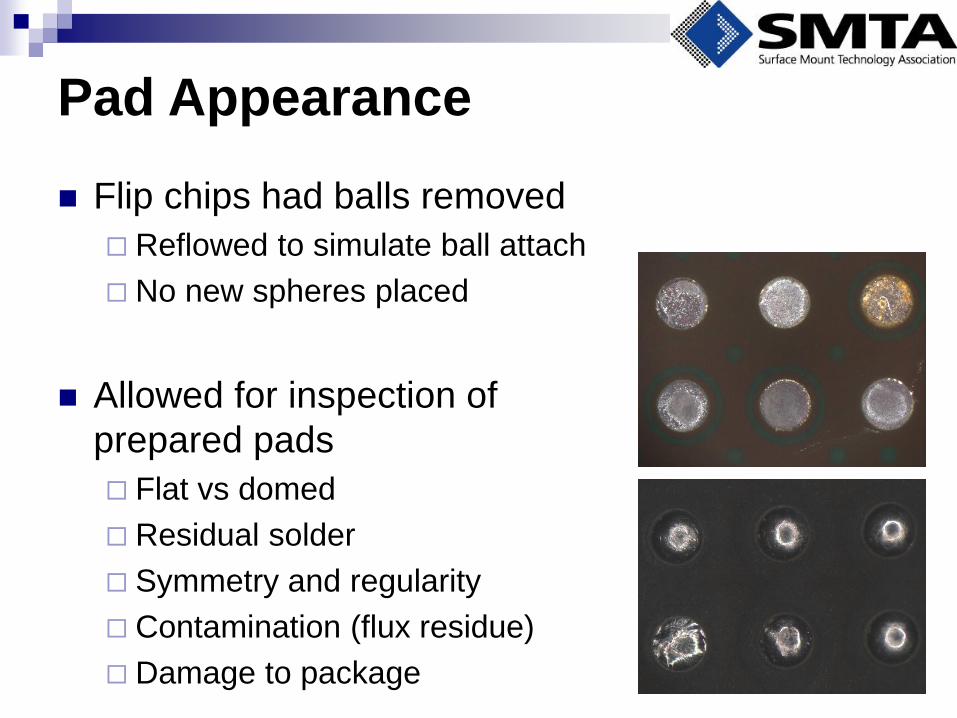
Pad Appearance
Flip chips had balls removed
Reflowed to simulate ball attach
No new spheres placed
Allowed for inspection of
prepared pads
Flat vs domed
Residual solder
Symmetry and regularity
Contamination (flux residue)
Damage to package
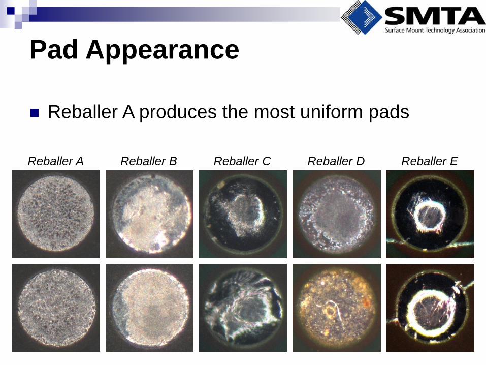
Pad Appearance
Reballer C Reballer E Reballer D Reballer B Reballer A
Reballer A produces the most uniform pads
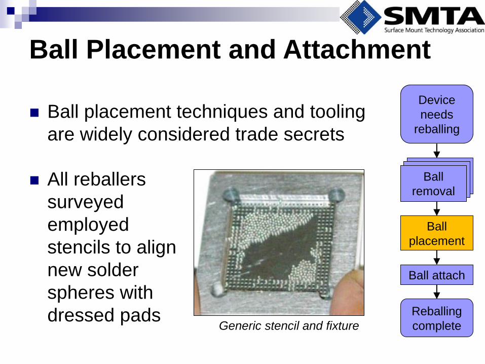
Ball Placement and Attachment
All reballers
surveyed
employed
stencils to align
new solder
spheres with
dressed pads Generic stencil and fixture
Device
needs
reballing
Ball
placement
Ball attach
Reballing
complete
Ball
removal Ball
removal Ball
removal
Ball placement techniques and tooling
are widely considered trade secrets
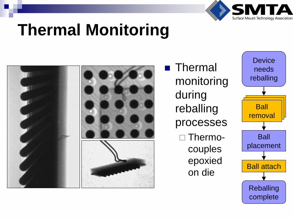
Thermal Monitoring
Thermal
monitoring
during
reballing
processes
Thermo-
couples
epoxied
on die
Device
needs
reballing
Ball
placement
Ball attach
Reballing
complete
Ball
removal Ball
removal Ball
removal
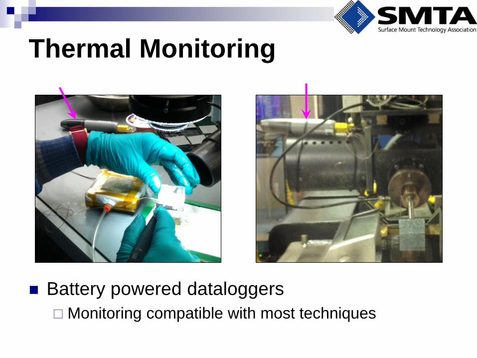
Thermal Monitoring
Battery powered dataloggers
Monitoring compatible with most techniques
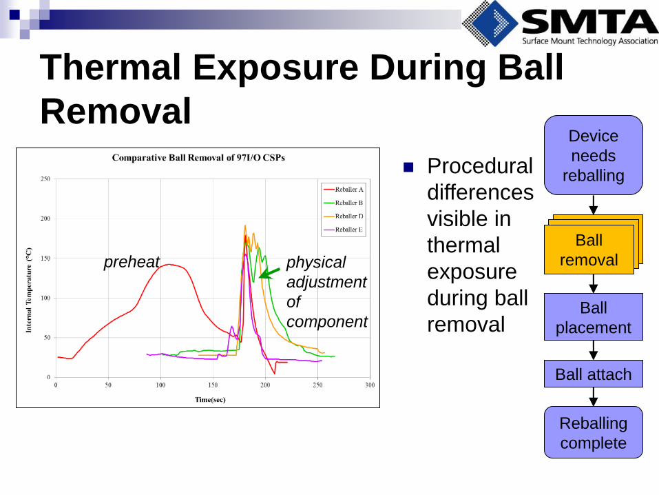
Thermal Exposure During Ball
Removal
Procedural
differences
visible in
thermal
exposure
during ball
removal
preheat physical
adjustment
of
component
Device
needs
reballing
Ball
placement
Ball attach
Reballing
complete
Ball
removal Ball
removal Ball
removal
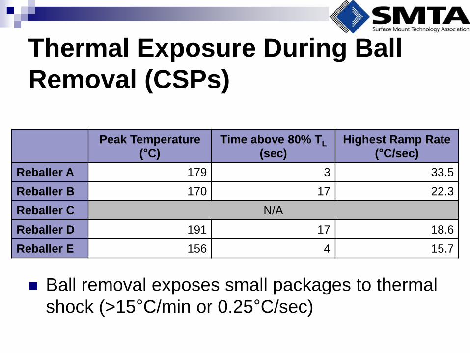
Thermal Exposure During Ball
Removal (CSPs)
Peak Temperature
(°C)
Time above 80% TL
(sec)
Highest Ramp Rate
(°C/sec)
Reballer A 179 3 33.5
Reballer B 170 17 22.3
Reballer C N/A
Reballer D 191 17 18.6
Reballer E 156 4 15.7
Ball removal exposes small packages to thermal
shock (>15°C/min or 0.25°C/sec)

Thermal Exposure During Ball
Removal
Procedural
differences
visible in
thermal
exposure
during
removal
preheat
physical
adjustment
of
component
hot air
knife
Device
needs
reballing
Ball
placement
Ball attach
Reballing
complete
Ball
removal Ball
removal Ball
removal
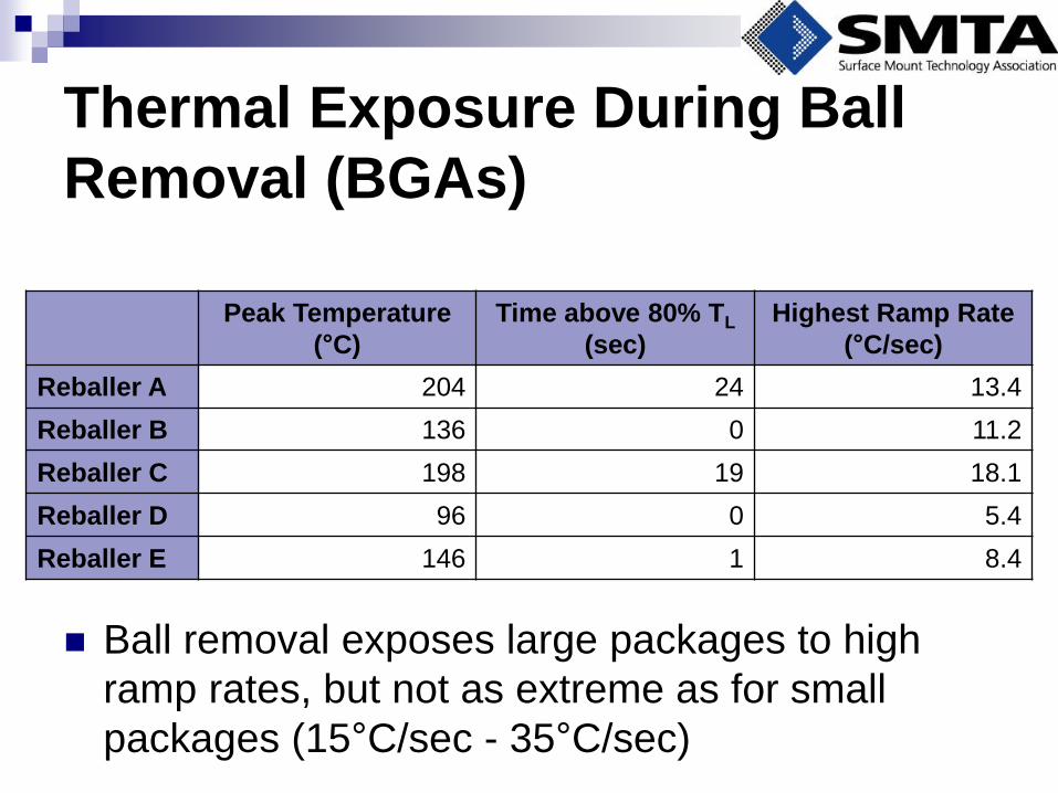
Thermal Exposure During Ball
Removal (BGAs)
Peak Temperature
(°C)
Time above 80% TL
(sec)
Highest Ramp Rate
(°C/sec)
Reballer A 204 24 13.4
Reballer B 136 0 11.2
Reballer C 198 19 18.1
Reballer D 96 0 5.4
Reballer E 146 1 8.4
Ball removal exposes large packages to high
ramp rates, but not as extreme as for small
packages (15°C/sec - 35°C/sec)
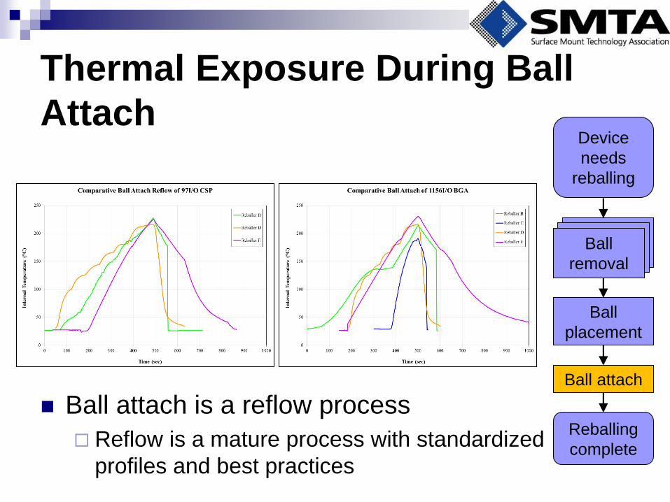
Thermal Exposure During Ball
Attach
Ball attach is a reflow process
Reflow is a mature process with standardized
profiles and best practices
Device
needs
reballing
Ball
placement
Ball attach
Reballing
complete
Ball
removal Ball
removal Ball
removal

Thermal Exposure During Ball
Attach (CSPs)
Peak Temperature
(°C)
Time above 80% TL
(sec)
Highest Ramp Rate
(°C/sec)
Reballer A N/A
Reballer B 228 330* 0.7
Reballer C N/A
Reballer D 216 268 0.6
Reballer E 225 290 0.7
Ball attach exposes CSPs to higher
temperatures and longer durations than ball
removal
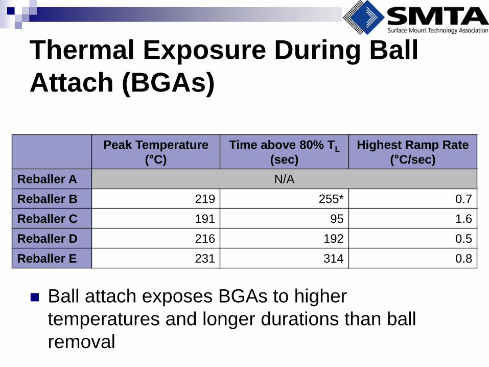
Thermal Exposure During Ball
Attach (BGAs)
Peak Temperature
(°C)
Time above 80% TL
(sec)
Highest Ramp Rate
(°C/sec)
Reballer A N/A
Reballer B 219 255* 0.7
Reballer C 191 95 1.6
Reballer D 216 192 0.5
Reballer E 231 314 0.8
Ball attach exposes BGAs to higher
temperatures and longer durations than ball
removal
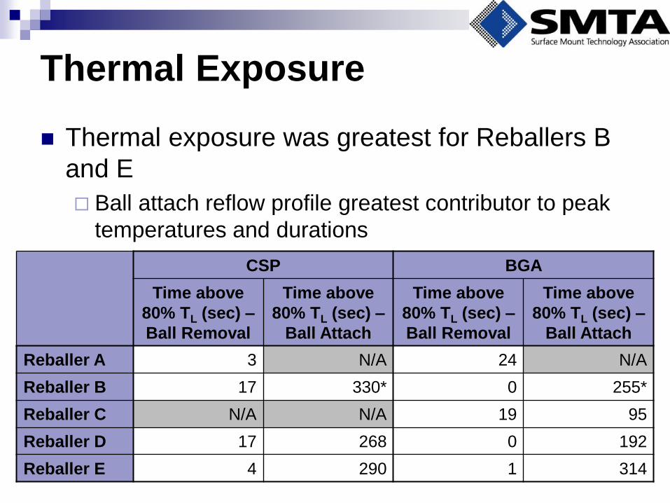
Thermal Exposure
Thermal exposure was greatest for Reballers B
and E
Ball attach reflow profile greatest contributor to peak
temperatures and durations
CSP BGA
Time above
80% TL (sec) –
Ball Removal
Time above
80% TL (sec) –
Ball Attach
Time above
80% TL (sec) –
Ball Removal
Time above
80% TL (sec) –
Ball Attach
Reballer A 3 N/A 24 N/A
Reballer B 17 330* 0 255*
Reballer C N/A N/A 19 95
Reballer D 17 268 0 192
Reballer E 4 290 1 314
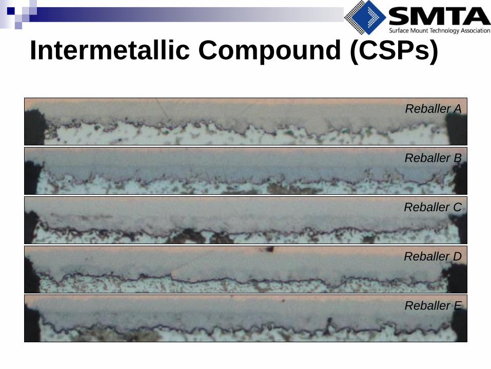
Intermetallic Compound (CSPs)
Reballer C
Reballer E
Reballer D
Reballer B
Reballer A
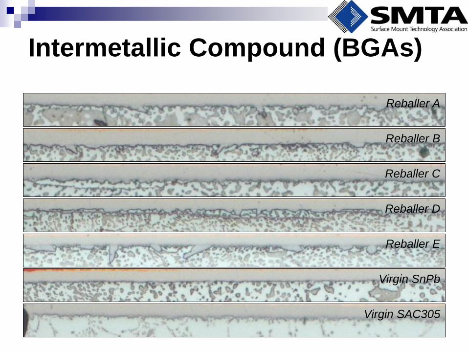
Intermetallic Compound (BGAs)
Reballer C
Reballer E
Reballer D
Reballer B
Reballer A
Virgin SAC305
Virgin SnPb
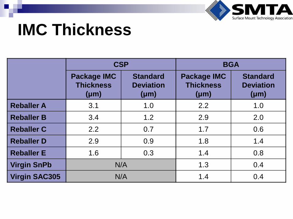
IMC Thickness
CSP BGA
Package IMC
Thickness
(μm)
Standard
Deviation
(μm)
Package IMC
Thickness
(μm)
Standard
Deviation
(μm)
Reballer A 3.1 1.0 2.2 1.0
Reballer B 3.4 1.2 2.9 2.0
Reballer C 2.2 0.7 1.7 0.6
Reballer D 2.9 0.9 1.8 1.4
Reballer E 1.6 0.3 1.4 0.8
Virgin SnPb N/A 1.3 0.4
Virgin SAC305 N/A 1.4 0.4
Intermetallic Compound Growth
Reballers who prioritize flat pad dressing exhibit
greatest IMC growth
Thermal exposure alone does not determine
thickness of IMC for reballed joints
Reballers B and E exposed components to highest
temperatures for longest durations
Reballer B has thickest IMC
Reballer E has thinnest IMC
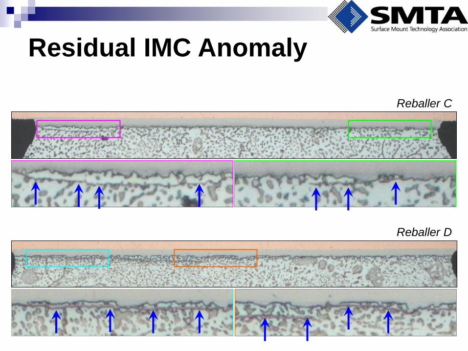
Residual IMC Anomaly
Reballer D
Reballer C
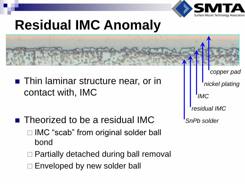
Residual IMC Anomaly
Thin laminar structure near, or in
contact with, IMC
Theorized to be a residual IMC
IMC “scab” from original solder ball
bond
Partially detached during ball removal
Enveloped by new solder ball
copper pad
nickel plating
IMC
residual IMC
SnPb solder
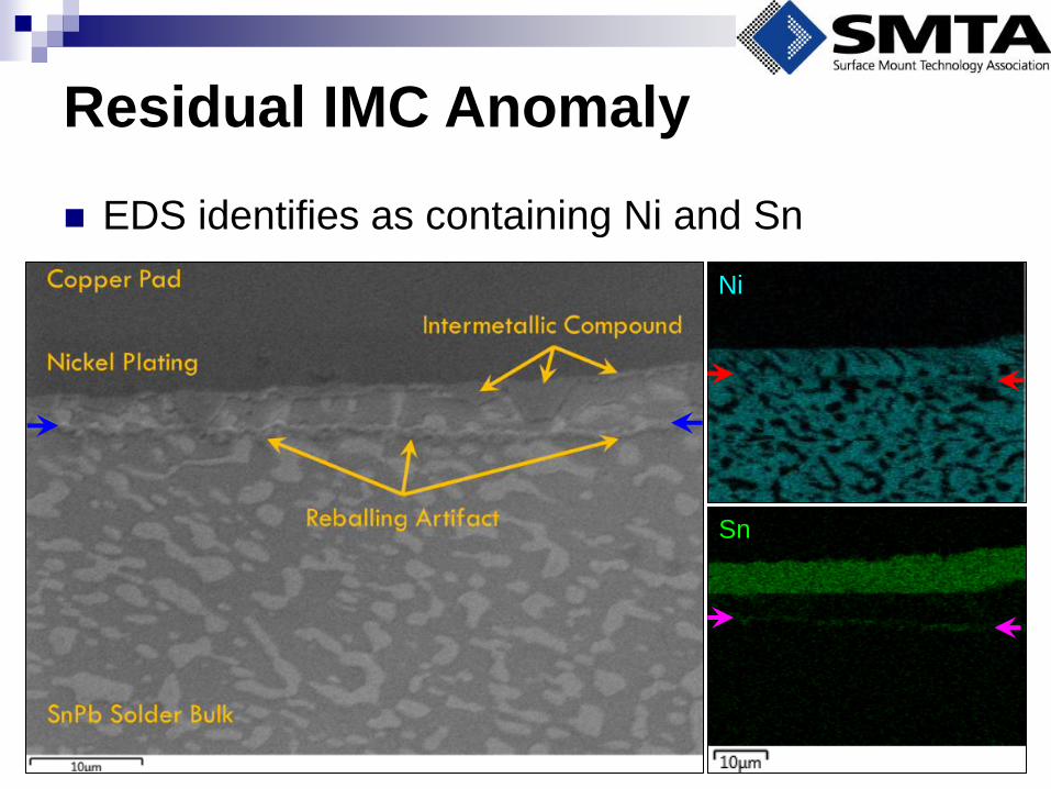
EDS identifies as containing Ni and Sn
Residual IMC Anomaly
Sn
Ni
Two types of ball removal processes exist
Melting and wicking
Dissolution in molten solder
Two priorities among reballers
Dress pads to a flat profile
Disturb the IMC as little as possible, results in domed
pads
Findings: Ball Removal
Techniques
Findings: Technique and
Thermal Exposure
Thermal exposure is minimal for all ball removal
techniques
Greatest contribution to thermal exposure is ball
attach reflow profile
Findings: Appearance of
Intermetallic Compound
IMC thickness is greater than that of non-
reballed components
IMC thickness does not correlate well with
thermal exposure
A free-floating IMC was observed on some
components
Discussion: IMC Growth
The most IMC growth was observed for reballers
who prioritized a flat pad appearance
Does this stimulate growth of the IMC?
Exposure of the IMC and physical abrasion to
the crystal boundaries provides high energy
sites for nucleation following reflow
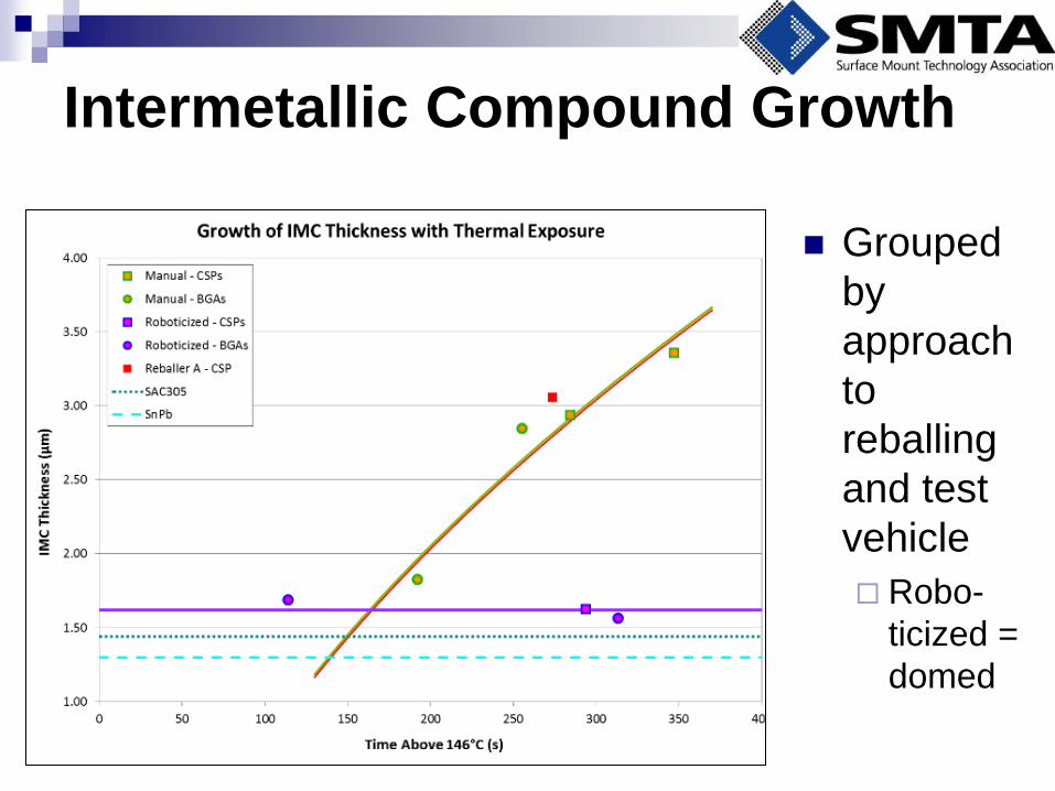
Intermetallic Compound Growth
Grouped
by
approach
to
reballing
and test
vehicle
Robo-
ticized =
domed
Discussion: Residual IMC
The free-floating IMC was observed on
components with solder domes on pads or
dressed flat
Fractures due to thermal cycling, mechanical shock,
and vibration testing were not observed to propagate
along such an artifact
Conclusions
Flat pad dressing increases IMC thickness
Intermetallic compound exhibits brittle fracture
behavior
Excessive growth of IMC should be avoided for high
stress applications
Pre-existing IMC should be disturbed as little as
possible
Dressing pads to a domed appearance is
recommended for applications where shock may be a
concern
Acknowledgements
This work was supported by a Small Business
Innovation Research grant from the Office of the
Secretary of Defense.
The author also wishes to thank the participating
reballers for their warm welcome and insight into
the reballing process.

Questions?
Contact me:
Joelle Arnold
301-640-5809
www.dfrsolutions.com