Embed Size (px)
Citation preview

International Journal of Mathematics Trends and Technology – Volume 2 Issue3 Number 2 – Dec 2011
ISSN: 2231-5373 http://www.ijpttjournal.org Page 26
Impact of Tie Beams in Seismic Investigation of Moment-Resisting Frames
P. Sachithanantham1, Dr. S. Elavenil
2, Dr. S. Sankaran
3
1-Asst. Professor, Department of Civil Engineering,
Bharath University, Selaiyur, Chennai, Tamilnadu, India.
2-Professor, Department of Civil Engineering,
SRM University, Kattankulathur, Tamilnadu, India,
3-Dean of Civil Engineering,
Arunai College of Engineering, Thiruvannamalai, Tamilnadu, India
Abstract: Due to the frequent occurrence of earthquakes sudden failure of structures leads to maximum loss of lives and property. Multistoryed buildings are affected severely since they are more susceptible to damage during earthquakes. Due to the large lateral displacements, both structural and non structural distress and damages are observed in reinforced concrete frames. The current codal provisions emphasis lateral forces rather than lateral displacements. The maximum lateral displacements are checked at the end of the design process to satisfy serviceability requirements. In recent times a growing interest in performance based design procedures in which lateral displacements are emphasized than lateral forces. From the lessons learnt due to past earthquakes is it observed that large numbers of multistoryed buildings are severely affected. This leads to increased awareness in the analysis of multistoreyed buildings. In this study seismic analysis of five stoyred reinforced cement concrete frames is carried with and without the horizontal bracing element at substructure level. The analysis is carried out using standard software package. The results are compared to study the earthquake resistant behaviour of the multistoryed building frame systems with and without horizontal brace elements.
INTRODUCTION
Ordinary reinforced concrete moment-resisting frames (OMRF) and special reinforced
concrete moment-resisting frames (SMRF) with and without shear wall are very popular in
construction of multistoryed buildings. The percentage of permissible increase in allowable
bearing pressure or resistance of soil given in IS 1893 (Part I) as fifty for type I rock or hard
soil for the foundation of combined or isolated RCC footing with tie beams and twenty five
for type II medium soil and type III soft soils for the foundation of RCC isolated footing
without tie beams or unreinforced strip foundations. IS 1893, also specifies isolated RCC
footing without tie beams or un-reinforced strip foundations shall not be permitted in soft
soils with N value less than ten. In the analysis of building frame systems this is considered
and the tie beams are provided as plinth beams to distribute the masonry loads. Much
attention is given only for the provision of plinth beams connecting the footings depending on
the functional plans, rather than connecting the footings with tie beams.
In this paper the investigation on seismic analysis of building frame systems with and without
tie beams connecting isolated footings are considered. Building frame system comprising five
floors with each storey with a height of 3.5 m is adopted for the analysis. The building plan
consisting six modules of 12 m x 10 m and three modules of 12 m x 3 m as shown in figure 1
is considered for the seismic analysis.
International Journal of Mathematics Trends and Technology – Volume 2 Issue3 Number 2 – Dec 2011
ISSN: 2231-5373 http://www.ijpttjournal.org Page 27
METHODOLOGY
Structural Modelling
To investigate the influence of tie beams connecting the footings, building frame systems
with and with out tie beams are considered and designated as
1. BFS I - Building frame system with tie beam at plinth level
2. BFS II - Building frame system without tie beam at plinth level
Building frame system BFS I is modelled by assigning the corresponding coordinates in x, y
and z directions. Element connectivity is carried by connecting the nodes. For BFS I at
plinth level tie beams are connected with appropriated nodes connecting all the nodes as
shown in figure 2. For BFS II, at plinth level plinth beams are connected only with nodes
where ever masonry walls are to be constructed as shown in figure 3.
4 m 4 m
4 m
4 m
4 m 4 m 4 m
4 m
4 m4 m 4 m
3 m
4 m4 m
10 m10 m 10 m10 m
4 m4 m 4 m 4 m
4 m
4 m4 m
3 m3 m 3 m
4 m
4 m4 m
4 m
4 m 4 m
10 m
4 m
10 m
4 m4 m4 m 4 m
4 m4 m
4 m4 m
4 m
10 m10 m
Load 1XY
Z
Figure 1 Functional building plan
The geometry of the building frame system is modelled by defining and assigning the
member sizes and member properties for and beams and columns as presented in table 1.

International Journal of Mathematics Trends and Technology – Volume 2 Issue3 Number 2 – Dec 2011
ISSN: 2231-5373 http://www.ijpttjournal.org Page 28
3 m 3 m
4 m
3 m
10 m
4 m
3 m
4 m
10 m
4 m
10 m 10 m
4 m
10 m 10 m
4 m4 m
4 m
3 m
4 m4 m 4 m
10 m 10 m
3 m 3 m
10 m
4 m
4 m
10 m
3 m 3 m
4 m
4 m
4 m 4 m
10 m
4 m
10 m10 m10 m10 m
4 m
4 m
4 m 4 m4 m 4 m
10 m10 m10 m
4 m
10 m
4 m
10 m
4 m 4 m
4 m
4 m 4 m
4 m
4 m4 m 4 m
4 m
3 m
XY
Z
Figure 2 Building frame system with tie beam at plinth level (BFS I)
4 m 4 m
4 m
4 m
4 m 4 m 4 m
4 m
4 m4 m 4 m
3 m
4 m4 m
10 m10 m 10 m10 m
4 m4 m 4 m 4 m
4 m
4 m4 m
3 m3 m 3 m
4 m
4 m4 m
4 m
4 m 4 m
10 m
4 m
10 m
4 m4 m4 m 4 m
4 m4 m
4 m4 m
4 m
10 m10 m
Load 1XY
Z
Figure 3 Building frame system without tie beam at plinth level (BFS II)
International Journal of Mathematics Trends and Technology – Volume 2 Issue3 Number 2 – Dec 2011
ISSN: 2231-5373 http://www.ijpttjournal.org Page 29
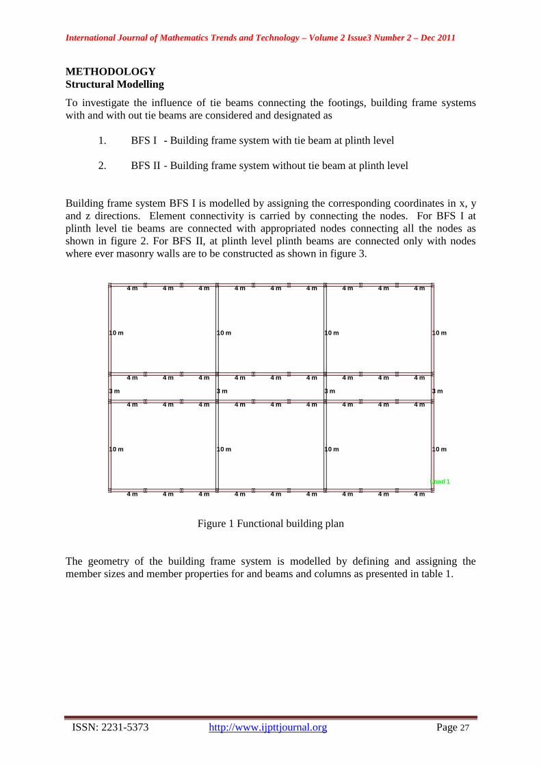
Table 1 Geometrical Properties for BFS I and BFS II
Description Dimension, mm
C1 – Column 300 x 300
C2 – Column 450 x 300
PB 1 – Plinth Beam 450 x 300
TB 1 – Tie Beam 450 x 300
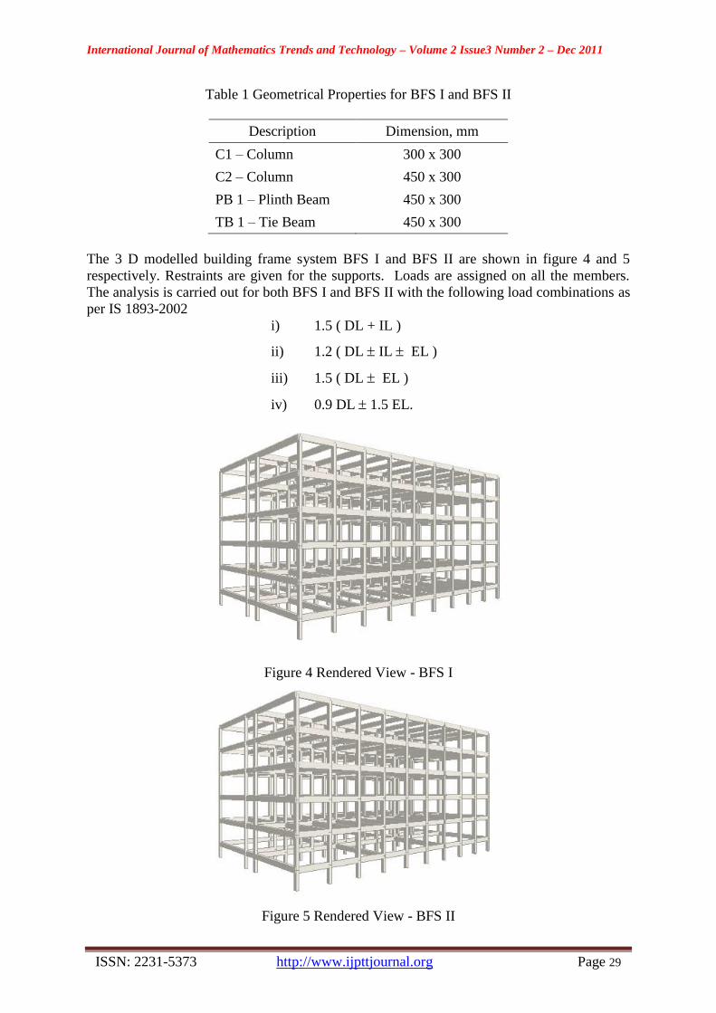
The 3 D modelled building frame system BFS I and BFS II are shown in figure 4 and 5
respectively. Restraints are given for the supports. Loads are assigned on all the members.
The analysis is carried out for both BFS I and BFS II with the following load combinations as
per IS 1893-2002
i) 1.5 ( DL + IL )
ii) 1.2 ( DL IL EL )
iii) 1.5 ( DL EL )
iv) 0.9 DL 1.5 EL.
Figure 4 Rendered View - BFS I
Figure 5 Rendered View - BFS II

International Journal of Mathematics Trends and Technology – Volume 2 Issue3 Number 2 – Dec 2011
ISSN: 2231-5373 http://www.ijpttjournal.org Page 30
SEISMIC ANALYSIS
Seismic analysis is performed by response spectrum method with the inputs shown in table 2
and the response quantities are arrived.
Table 2 Seismic Input parameters for BFS I and BFS II
Description Value
Zone factor 0.16
Response reduction factor 5
Importance factor 1
Soil factor Hard soil
Damping 5%
Number of Modes 6
RESULTS AND DISCUSSION
From results of dynamic analysis the story drifts in X and Z direction are calculated at each
level of storey height for both BFS I and BFS II and presented in table 3. It is inferred that the
story drift in BFS II is relatively larger than BFS I in both X and Z directions.
Table 3 Storey Drift
Storey
Height, m
BFS I BFS II
Drift – X,
mm
Drift – Z,
mm
Drift – X,
mm
Drift – Z,
mm
0 1.908 2.509 3.198 4.003
3.5 2.646 3.477 4.273 4.754
7 2.247 2.952 3.634 2.458
10.5 1.691 2.228 2.721 1.716
14 0.996 1.315 1.583 1.047
17.5 0.282 0.371 0.376 0.399
From the post processor results the maximum nodal displacements in X and Z directions of
each storey are calculated and presentable in table 4. A plot is made between storey height
and maximum nodal displacement as shown in figure 6. From this plot it is observed that the
nodal displacement increases with storey height. The nodal displacements of BFS II are
more compared with BFS I. This behaviour indicates the influence of tie beam in BFS I.

International Journal of Mathematics Trends and Technology – Volume 2 Issue3 Number 2 – Dec 2011
ISSN: 2231-5373 http://www.ijpttjournal.org Page 31
Table 4 Maximum Nodal Displacement
Storey
Height, m
BFS I BFS II
Displacement-
X, mm
Displacement-
Z, mm
Displacement-
X, mm
Displacement-
Z, mm
0 2.058 3.887 3.269 6.458
3.5 4.911 9.271 7.625 13.405
7 7.322 13.877 11.317 16.556
10.5 9.121 17.422 14.062 19.635
14 10.15 19.636 15.621 21.755
17.5 10.399 20.479 15.926 22.74
Maximum Displacement
0
5
10
15
20
25
0 3.5 7 10.5 14 17.5
Storey Height, m
Maxim
um
dis
pla
cm
en
t ,
mm
BFS I X
BFS I - Z
BFS II X
BFS II Z
Figure 6 Relationship between storey height and maximum nodal displacement
The maximum shear force, positive and negative bending moments of beams in each storey
of both BFS I and BFS II are taken from the analysis results and presented in table 5. From
this table it is inferred that the maximum shear force, positive and negative bending moments
of beams in each storey is appreciably more in BFS II when compared to BSF I, which
indicates the influence of tie beams in BFS I.
From the dynamic analysis frequency, period and mass participation in X, Y and Z directions
are calculated and presented in table 6 and 7 for BFS I and BFS II respectively. A plot is
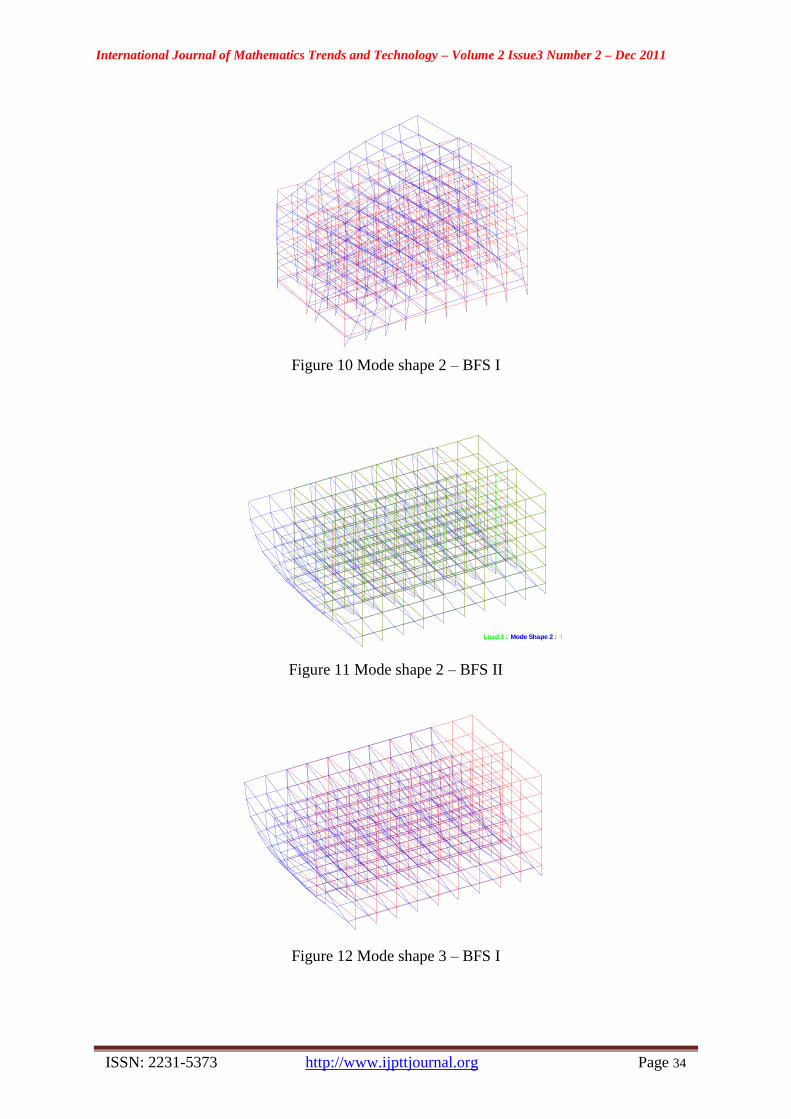
made between mode and frequency for both BFS I and BFS II as shown in figure 7. From the
plot it is observed that the frequency is less in case of BFS II compared to BFS I due to the
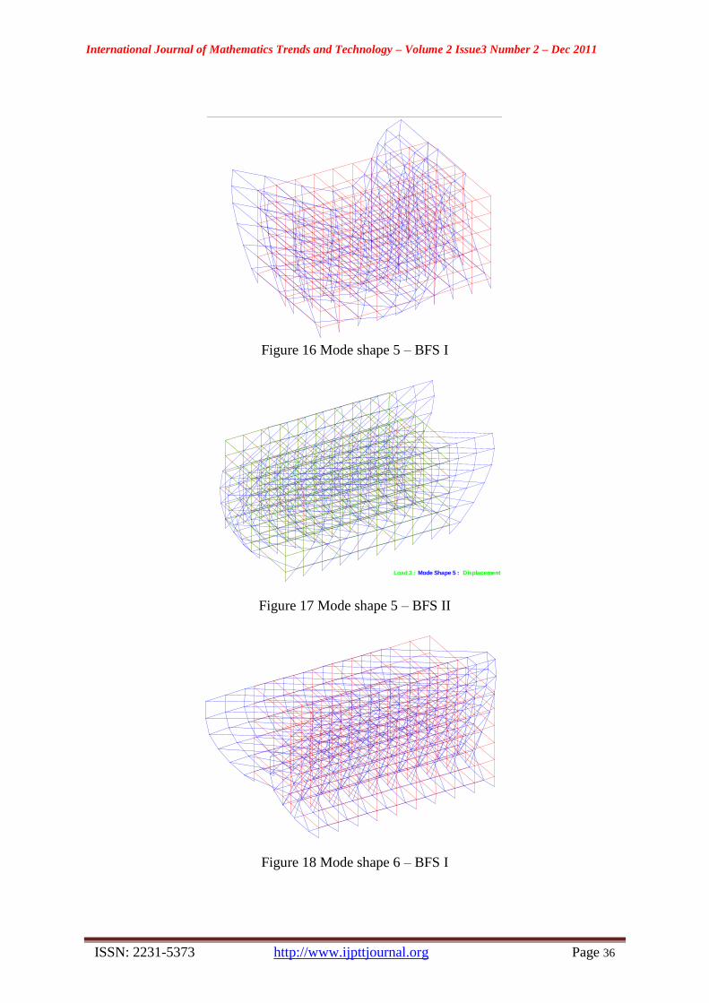
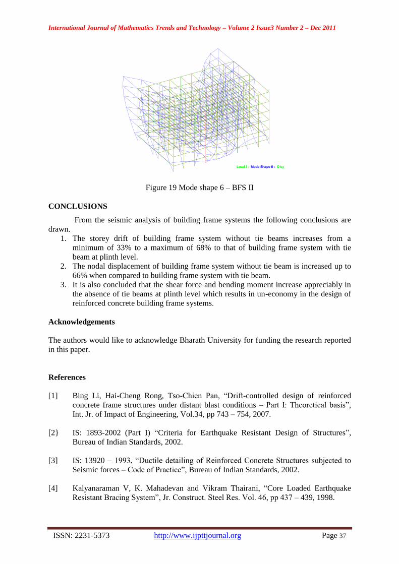
presence of tie beams at the plinth level. Figure 8 to 19 show the various mode shapes for
both BFS I and BFS II.

International Journal of Mathematics Trends and Technology – Volume 2 Issue3 Number 2 – Dec 2011
ISSN: 2231-5373 http://www.ijpttjournal.org Page 32
Table 5 Maximum Shear Force and Bending Moment - Beams
Storey
Height, m
BFS I BFS II
Shear Force
(Max), kN
Bending Moment,
kNm Shear Force
(Max), kN
Bending Moment,
kNm
Positive Negative Positive Negative
0 39.901 66.533 -66.126 101.052 151.578 -151.578
3.5 32.764 53.846 -53.517 67.202 100.804 -100.804
7 24.796 41.932 -41.679 42.564 63.847 -63.847
10.5 15.581 26.582 -27.171 23.56 35.341 -35.934
14 5.955 12.886 -14.785 6.951 19.999 -21.293
17.5 5.919 9.235 -9.416 5.299 11.492 -9.627
Table 6 Frequencies and Mass Participation - BFS I
Mode
Frequency,
Hz
Period, s
Participation
X, %
Participation
Y, %
Participation
Z, %
1 0.435 2.3 0 0 67.786
2 0.62 1.612 0 0 16.038
3 0.714 1.4 83.293 0 0
4 0.936 1.069 0 0 0.157
5 0.996 1.004 0 0 0.062
6 1.045 0.957 0.868 0 0
Table 7 Frequencies and Mass Participation - BFS II
Mode
Frequency,
Hz
Period, s
Participation
X, %
Participation
Y, %
Participation
Z, %
1 0.438 2.281 0 0 71.023
2 0.537 1.862 84.837 0 0
3 0.597 1.674 0 0 17.58
4 0.813 1.23 0 0 0.85
5 0.917 1.091 0.282 0 0
6 1.008 0.992 0 0 0.238

International Journal of Mathematics Trends and Technology – Volume 2 Issue3 Number 2 – Dec 2011
ISSN: 2231-5373 http://www.ijpttjournal.org Page 33
Mode vs Frequency
0.3
0.4
0.5
0.6
0.7
0.8
0.9
1
1.1
0 1 2 3 4 5 6
Mode
Freq
uen
cy,
Hz
BFS I
BFS II
Figure 7 Relationship between mode and frequency
XY
Z
Figure 8 Mode shape 1 – BFS I
DisplacementMode Shape 1 : Load 3 :
XY
Z
Figure 9 Mode shape 1 – BFS II
International Journal of Mathematics Trends and Technology – Volume 2 Issue3 Number 2 – Dec 2011
ISSN: 2231-5373 http://www.ijpttjournal.org Page 34
XY
Z
Figure 10 Mode shape 2 – BFS I
DisplacementMode Shape 2 : Load 3 :
XY
Z
Figure 11 Mode shape 2 – BFS II
XY
Z
Figure 12 Mode shape 3 – BFS I

International Journal of Mathematics Trends and Technology – Volume 2 Issue3 Number 2 – Dec 2011
ISSN: 2231-5373 http://www.ijpttjournal.org Page 35
DisplacementMode Shape 3 : Load 3 :
XY
Z
Figure 13 Mode shape 3 – BFS II
XY
Z
Figure 14 Mode shape 4 – BFS I
DisplacementMode Shape 4 : Load 3 :
XY
Z
Figure 15 Mode shape 4 – BFS II
International Journal of Mathematics Trends and Technology – Volume 2 Issue3 Number 2 – Dec 2011
ISSN: 2231-5373 http://www.ijpttjournal.org Page 36
XY
Z
Figure 16 Mode shape 5 – BFS I
DisplacementMode Shape 5 : Load 3 :
XY
Z
Figure 17 Mode shape 5 – BFS II
XY
Z
Figure 18 Mode shape 6 – BFS I
International Journal of Mathematics Trends and Technology – Volume 2 Issue3 Number 2 – Dec 2011
ISSN: 2231-5373 http://www.ijpttjournal.org Page 37
DisplacementMode Shape 6 : Load 3 :
XY
Z
Figure 19 Mode shape 6 – BFS II
CONCLUSIONS
From the seismic analysis of building frame systems the following conclusions are
drawn.
1. The storey drift of building frame system without tie beams increases from a
minimum of 33% to a maximum of 68% to that of building frame system with tie
beam at plinth level.
2. The nodal displacement of building frame system without tie beam is increased up to
66% when compared to building frame system with tie beam.
3. It is also concluded that the shear force and bending moment increase appreciably in
the absence of tie beams at plinth level which results in un-economy in the design of
reinforced concrete building frame systems.
Acknowledgements
The authors would like to acknowledge Bharath University for funding the research reported
in this paper.
References
[1] Bing Li, Hai-Cheng Rong, Tso-Chien Pan, “Drift-controlled design of reinforced
concrete frame structures under distant blast conditions – Part I: Theoretical basis”,
Int. Jr. of Impact of Engineering, Vol.34, pp 743 – 754, 2007.
[2} IS: 1893-2002 (Part I) “Criteria for Earthquake Resistant Design of Structures”,
Bureau of Indian Standards, 2002.
[3] IS: 13920 – 1993, “Ductile detailing of Reinforced Concrete Structures subjected to
Seismic forces – Code of Practice”, Bureau of Indian Standards, 2002.
[4] Kalyanaraman V, K. Mahadevan and Vikram Thairani, “Core Loaded Earthquake
Resistant Bracing System”, Jr. Construct. Steel Res. Vol. 46, pp 437 – 439, 1998.