Embed Size (px)
Citation preview

International Journal of Engineering Applied Sciences and Technology, 2021
Vol. 6, Issue 1, ISSN No. 2455-2143, Pages 319-324
Published Online May 2021 in IJEAST (http://www.ijeast.com)
319
IMPACT OF UPFC ON THE POWER
QUALITY IN GRID Puneet
Assistant Professor,
Guru Nanak Dev Engineering College,
Ludhiana, Punjab, India
Baljeet Singh Assistant Professor,
Guru Nanak Dev Engineering College,
Ludhiana, Punjab, India
Abstract: To reduce the complexity and
improving effectiveness of power system UPFC is
one of the most effective and reliable device. In
this impact of using UPFC is studied for the model
grid prepared using MATLAB having two
generators and one major load centre. The flow of
active and reactive power, voltage stability and
fault recovery time is studied for this model whose
results are given by the MATLAB Simulink. The
results clearly show the improvement in power
quality in grid at system and load buses and also
improvement in other various factors has been
observed.
Keywords: FACTS, UPFC, STATCOM, SSSC,
Active and Reactive Power
I. INTRODUCTION
These days the operation of power system is very
complex due to which some problems can be noticed
while transmitting power from one zone to another.
Some of these limitations are like short circuiting,
oscillation in system, transient stability etc [1]. To
eradicate these issues FACTS technology is found to
be very efficient [2]. FACTS comprises power
electronic equipments like GTO, thyristor and others
which helps in effective utilization of power that can be transferred with maximum value over
interconnected systems with proper control,
reliability and improvisation. System stability can be
either increased or decreased and it depends upon the
control and optimum placement of FACTS controller
[3]. By calculating the active and reactive power the
steady state operation condition can be obtained [4].
UPFC is the device which had ability to control both
the active and reactive power [5]. UPFC also can
control the line parameters i.e. impedance, phase
angle and voltage [6]. To transfer maximum power
and taking proper control over active and reactive
power UPFC is combined with the controller of STATCOM and SSSC is used in the system [7].
STATCOM is able to generate or absorb reactive
power that can be independently controlled as it is a
voltage source converter whereas SSSC is type of
solid state voltage source inverter which can generate
controllable AC voltage [8]. UPFC works on a
condition that there should not be distortion in a sine
wave of the source [9].
The aim of the present work is to improve the voltage
profile and controlling real and reactive power for the
stability of power system operation. For this purpose
UPSC controller in combination with STATCOM
and SSSC is used wherever STATCOM is employed
for shunt controlling and SSSC for series attachment
for control of line. Both of them provide active and
reactive power support to the AC power system.
II. UNIFIED POWER FLOW
CONTROLLER
For a high voltage power transmission network a
UPFC quickly provides reactive power
compensation. The current is allowed to flow through
transmission line through the series transformer and
for this purpose UPFC uses a three phase controllable bridges. The controller is able to control both active
and reactive power through the transmission line.
UPFC plays a key role in improving the transient
stability and suppress oscillation in power system.
UPFC is one of the most flexible and reliable
controller that have been developed so far. These
have all the capabilities of voltage regulation, phase
shifting and series compensation.
International Journal of Engineering Applied Sciences and Technology, 2021
Vol. 6, Issue 1, ISSN No. 2455-2143, Pages 319-324
Published Online May 2021 in IJEAST (http://www.ijeast.com)
320
Figure 1 UPFC layout with VSCs
Figure 1 is representing UPFC having two VSCs
connected through a single DC terminal. Out of two
VSCs one is connected in shunt through coupling
transformer and another one is in series to the
transmission line through the transformer. DC power is made available by the capacitor bank connected to
both converters. The real and reactive power is
exchanges with the help of series converter and
reactive is generated and absorbed internally also by
the series convertor. Capacitor here generates and
absorbs real power. The first shunt convertor derives
real power from main supply and supply to feed the
demand of second convertor. Shunt convertor also
helps in maintaining the constant voltage across the
bus.
III. STATIC SYNCHRONOUS
COMPENSATOR
Static Synchronous Compensator (STATCOM) is
shunt connected FACTS device. It is mainly used for
reactive power control. In this work STATCOM is used to suppress voltage fluctuation to provide stable
voltage. It is a DC-DC voltage VSC where DC
capacitor acts as storage unit. Power electronic
switches there are used to derive sinusoidal output
from a DC source.
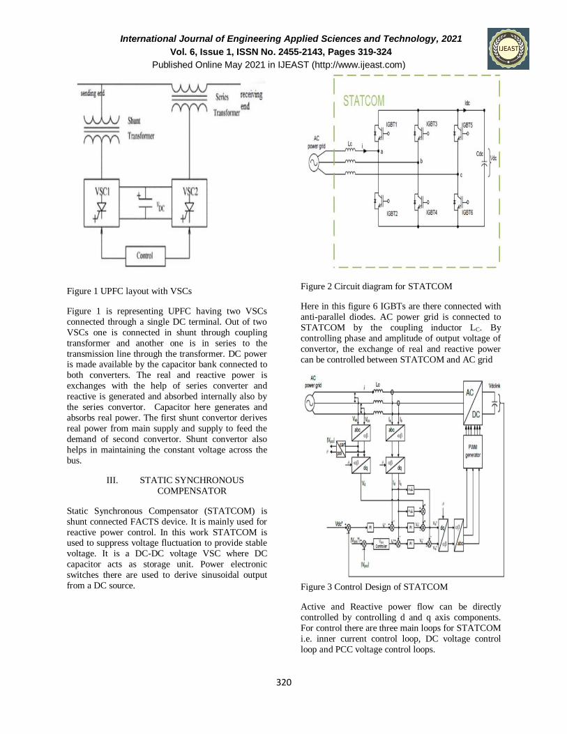
Figure 2 Circuit diagram for STATCOM
Here in this figure 6 IGBTs are there connected with
anti-parallel diodes. AC power grid is connected to
STATCOM by the coupling inductor LC. By
controlling phase and amplitude of output voltage of
convertor, the exchange of real and reactive power
can be controlled between STATCOM and AC grid
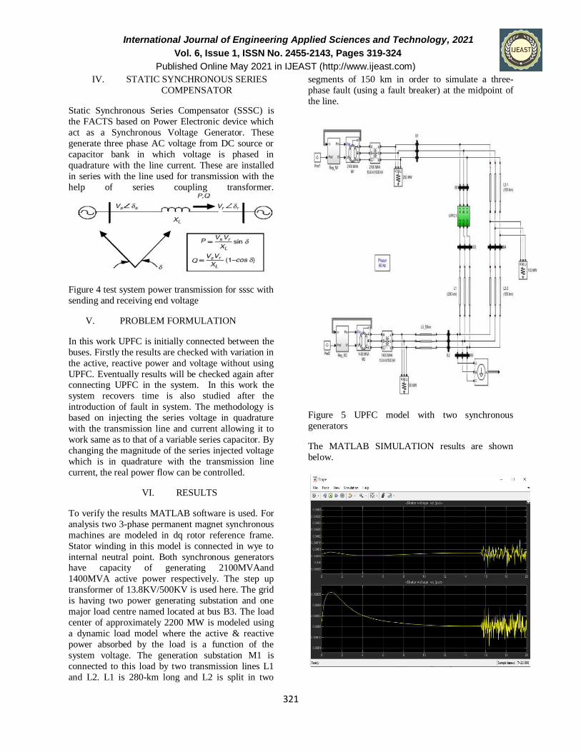
Figure 3 Control Design of STATCOM
Active and Reactive power flow can be directly
controlled by controlling d and q axis components.
For control there are three main loops for STATCOM
i.e. inner current control loop, DC voltage control
loop and PCC voltage control loops.
International Journal of Engineering Applied Sciences and Technology, 2021
Vol. 6, Issue 1, ISSN No. 2455-2143, Pages 319-324
Published Online May 2021 in IJEAST (http://www.ijeast.com)
321
IV. STATIC SYNCHRONOUS SERIES
COMPENSATOR
Static Synchronous Series Compensator (SSSC) is
the FACTS based on Power Electronic device which
act as a Synchronous Voltage Generator. These
generate three phase AC voltage from DC source or
capacitor bank in which voltage is phased in
quadrature with the line current. These are installed
in series with the line used for transmission with the
help of series coupling transformer.
Figure 4 test system power transmission for sssc with
sending and receiving end voltage
V. PROBLEM FORMULATION
In this work UPFC is initially connected between the
buses. Firstly the results are checked with variation in
the active, reactive power and voltage without using
UPFC. Eventually results will be checked again after connecting UPFC in the system. In this work the
system recovers time is also studied after the
introduction of fault in system. The methodology is
based on injecting the series voltage in quadrature
with the transmission line and current allowing it to
work same as to that of a variable series capacitor. By
changing the magnitude of the series injected voltage
which is in quadrature with the transmission line
current, the real power flow can be controlled.
VI. RESULTS
To verify the results MATLAB software is used. For
analysis two 3-phase permanent magnet synchronous
machines are modeled in dq rotor reference frame.
Stator winding in this model is connected in wye to
internal neutral point. Both synchronous generators have capacity of generating 2100MVAand
1400MVA active power respectively. The step up
transformer of 13.8KV/500KV is used here. The grid
is having two power generating substation and one
major load centre named located at bus B3. The load
center of approximately 2200 MW is modeled using
a dynamic load model where the active & reactive
power absorbed by the load is a function of the
system voltage. The generation substation M1 is
connected to this load by two transmission lines L1
and L2. L1 is 280-km long and L2 is split in two
segments of 150 km in order to simulate a three-
phase fault (using a fault breaker) at the midpoint of
the line.
Figure 5 UPFC model with two synchronous
generators
The MATLAB SIMULATION results are shown
below.
International Journal of Engineering Applied Sciences and Technology, 2021
Vol. 6, Issue 1, ISSN No. 2455-2143, Pages 319-324
Published Online May 2021 in IJEAST (http://www.ijeast.com)
322
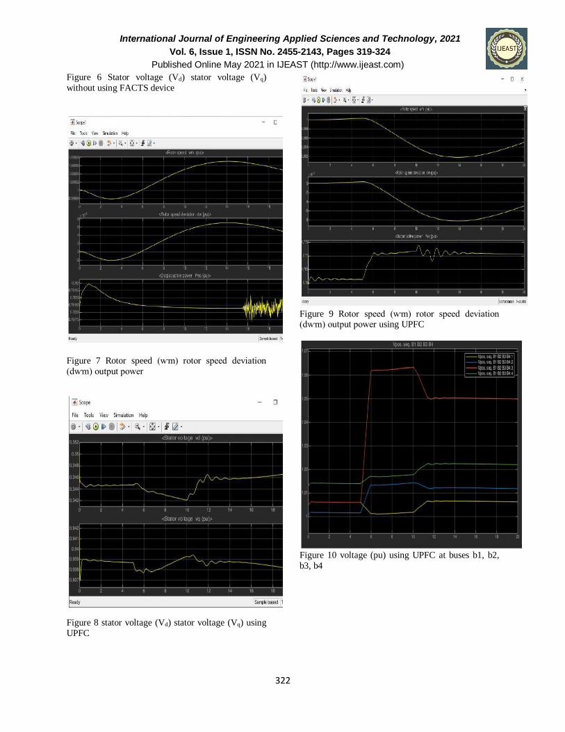
Figure 6 Stator voltage (Vd) stator voltage (Vq)
without using FACTS device
Figure 7 Rotor speed (ⱳm) rotor speed deviation
(dⱳm) output power
Figure 8 stator voltage (Vd) stator voltage (Vq) using
UPFC
Figure 9 Rotor speed (ⱳm) rotor speed deviation (dⱳm) output power using UPFC
Figure 10 voltage (pu) using UPFC at buses b1, b2,
b3, b4
International Journal of Engineering Applied Sciences and Technology, 2021
Vol. 6, Issue 1, ISSN No. 2455-2143, Pages 319-324
Published Online May 2021 in IJEAST (http://www.ijeast.com)
323
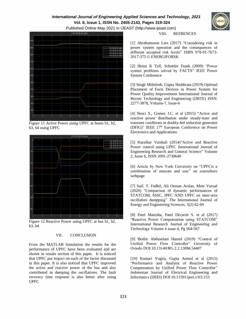
Figure 11 Active Power using UPFC at buses b1, b2,
b3, b4 using UPFC
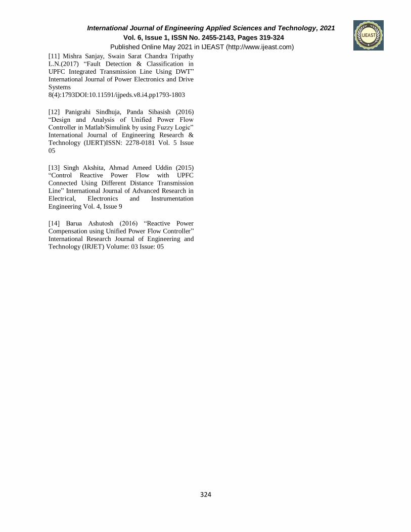
Figure 12 Reactive Power using UPFC at bus b1, b2, b3, b4
VII. CONCLUSION
From the MATLAB Simulation the results for the
performance of UPFC have been evaluated and are
shown in results section of this paper. It is noticed
that UPFC put impact on each of the factor discussed
in this paper. It is also noticed that UPFC improved
the active and reactive power of the bus and also
contributed in damping the oscillations. The fault recovery time response is also better after using
UPFC
VIII. REFRENCES
[1] Abrahamsson Lars (2017) “Considering risk in
power system operation and the consequences of
different accepted risk levels” ISBN 978-91-7673-2017-375 © ENERGIFORSK
[2] Heinz K Tyll, Schettler Frank (2009) “Power
system problems solved by FACTS” IEEE Power
System Conference
[3] Singh Mithilesh, Gupta Shubhrata (2019) Optimal
Placement of Facts Devices in Power System for
Power Quality Improvement International Journal of
Recent Technology and Engineering (IJRTE) ISSN:
2277-3878, Volume-7, Issue-6
[4] Nesci S., Gomez J.C. et al (2015) “Active and
reactive power distribution under steady-state and
transient conditions in doubly-fed induction generator
(DFIG)” IEEE 17th European Conference on Power
Electronics and Applications
[5] Kuralkar Vaishali (2014)“Active and Reactive
Power control using UPFC International Journal of
Engineering Research and General Science” Volume
2, Issue 6, ISSN 2091-2730649
[6] Article by New York University on “UPFCis a
combination of statcom and sssc” on coursehero
webpage
[7] Saif. T. Fadhil, Ali Osman Arslan, Mete Vurual
(2020) “Comparison of dynamic performances of
STATCOM, SSSC, IPFC AND UPFC on inter-area
oscillation dampping” The International Journal of
Energy and Engineering Sciences, 5(2) 62-69
[8] Patel Manisha, Patel Divyesh S. et al (2017)
“Reactive Power Compensation using STATCOM”
International Research Journal of Engineering and
Technology Volume 4 issue 4, Pg 564-567
[9] Beshir Abduselam Hamid (2019) “Control of
Unified Power Flow Controller” University of
Oviedo DOI:10.13140/RG.2.2.13084.54407
[10] Kumari Yogita, Gupta Anmol et al (2015)
“Performance and Analysis of Reactive Power
Compensation by Unified Power Flow Controller” Indonesian Journal of Electrical Engineering and
Informatics (IJEEI) DOI:10.11591/ijeei.v3i3.153
International Journal of Engineering Applied Sciences and Technology, 2021
Vol. 6, Issue 1, ISSN No. 2455-2143, Pages 319-324
Published Online May 2021 in IJEAST (http://www.ijeast.com)
324
[11] Mishra Sanjay, Swain Sarat Chandra Tripathy
L.N.(2017) “Fault Detection & Classification in
UPFC Integrated Transmission Line Using DWT”
International Journal of Power Electronics and Drive
Systems
8(4):1793DOI:10.11591/ijpeds.v8.i4.pp1793-1803
[12] Panigrahi Sindhuja, Panda Sibasish (2016)
“Design and Analysis of Unified Power Flow
Controller in Matlab/Simulink by using Fuzzy Logic” International Journal of Engineering Research &
Technology (IJERT)ISSN: 2278-0181 Vol. 5 Issue
05
[13] Singh Akshita, Ahmad Ameed Uddin (2015) “Control Reactive Power Flow with UPFC
Connected Using Different Distance Transmission
Line” International Journal of Advanced Research in
Electrical, Electronics and Instrumentation
Engineering Vol. 4, Issue 9
[14] Barua Ashutosh (2016) “Reactive Power
Compensation using Unified Power Flow Controller”
International Research Journal of Engineering and
Technology (IRJET) Volume: 03 Issue: 05