Embed Size (px)
DESCRIPTION
Impacts of IPsec Implementaion on LTE IP Connectivity
Citation preview
Aalto University School of Science and TechnologyFaculty of Electronics, Communications and Automation
Mehammedneja Kemal Rahmato
Impacts of IPsec Implementation on LTE IP Connectivity
Masters thesis submitted in partial fulfillment of the requirements for the Degree of Master ofScience in Technology.
Espoo, 09 April 2010
Supervisor Professor Jörg OttHelsinki University of Technology
Instructor Heikki AlmayNokia Siemens Networks
Aalto University School of Science and Technology Abstract of the Master’s Thesis
Author: Mehammedneja Kemal Rahmato
Name of the Thesis: Impacts of IPsec Implementation on LTE IP connectivity
Date: 09 April 2010 Language: English Number of Pages: 9 + 71
Faculty: Faculty of Electronics, Communications and Automation
Department: Communications Engineering
Professorship: Networking Technologies Code: S38
Supervisor: Prof. Jörg Ott, Aalto University School of Science and Technology
Instructor Heikki Almay, Nokia Siemens NetworksLong Term Evolution (LTE) is a result of the improvement of 3GPP’s radio access technology
towards a broadband mobile network with a higher datarate, improved quality and lower latency
services. Such high level service requirements and expectations of the LTE system are a direct
reflection of IP data traffic growth in mobile networks witnessed in the past few years.
To go along with the radio access network improvements, IP transport network to interconnect the
LTE radio access and core networks is identified as efficient and costoptimized solution. However,
using IP networks as a transport backbone in the LTE brings security vulnerabilities. To mitigate
the potential security risks, the Internet security framework IPsec use in the LTE transport is
proposed by 3GPP. Given the strict datarate and delay conditions for the LTE network, meeting the
required level of security using IPsec places a performance challenge on implementing the LTE
network.
This thesis work discusses impacts of IPsec implementation on the LTE transport based on
experimental tests conducted on an endtoend LTE IP connectivity solution. Particular emphasis is
given to 3GPP proposed IPsec configurations. The analysis and results of this work are helpful as
an input to design choices for IPsec implementation and use in the LTE network.
It was observed that IPsec protection for traffic composed solely of small packets, in the order of 64
to 256 bytes, degrades system performance to an unacceptably low level. However, when using a
more realistic network traffic mix, it was possible to show that an acceptable performance can be
obtained. It was also observed that fragmentation and reassembly after encryption presents more
than 50% reduction in system throughput.
Keywords: LTE, SAE, IPsec.

AcknowledgementI thank Allah for presenting this opportunity and giving me the strength to complete the work.
I thank my supervisor Prof. Jörg Ott and my instructor Heikki Almay for their continuous support in
accomplishing this work.
For all the support and mentoring, I thank my colleagues at Nokia Siemens Networks especially
Arto Mikkonen, Hannu Kallio, José Manuel Tapia Pérez, Risto Harju and Toni Nurminen.
Finally, I would like to extend my gratitude to my family, who have been supporting me all along.
Espoo, 09 April 2010
Mehammedneja Kemal Rahmato

Table of Contents
GLOSSARY ............................................................................................................................................................... I
1 INTRODUCTION ............................................................................................................................................ 1
1.1 PROBLEM .................................................................................................................................................. 41.2 OBJECTIVE AND SCOPE .............................................................................................................................. 41.3 APPROACH AND METHODOLOGY ................................................................................................................ 41.4 THESIS STRUCTURE ................................................................................................................................... 5
2 3GPP LTE/SAE SYSTEM OVERVIEW ......................................................................................................... 6
2.1 LONG TERM EVOLUTION (LTE) ................................................................................................................. 62.2 SYSTEM ARCHITECTURE EVOLUTION (SAE) ............................................................................................... 62.3 3GPP EVOLVED PACKET SYSTEM (EPS) ..................................................................................................... 62.4 FUNCTIONAL ELEMENTS OF THE EPS.......................................................................................................... 82.5 LTE TRANSPORT ....................................................................................................................................... 9
3 THREATS IN THE LTE SYSTEM ................................................................................................................10
3.1 THREATS TO CONTROL PLANE (CP) TRAFFIC .............................................................................................113.2 THREATS TO USER PLANE (UP) TRAFFIC ...................................................................................................123.3 THREATS TO MANAGEMENT PLANE TRAFFIC .............................................................................................143.4 SUMMARY ................................................................................................................................................14
4 SECURITY IN THE LTE SYSTEM ..............................................................................................................15
4.1 LAYERED SECURITY IN THE LTE SYSTEM ..................................................................................................154.2 NETWORK DOMAIN SECURITY (NDS/IP) ...................................................................................................16
4.2.1 IPsec Profiling in NDS/IP ....................................................................................................................164.2.2 Security Gateway (SEG) ......................................................................................................................17
4.3 EUTRAN SECURITY ...............................................................................................................................184.4 NAS SIGNALING SECURITY .......................................................................................................................194.5 LTE TRANSPORT SECURITY ......................................................................................................................19
4.5.1 Control and Management Plane traffic ................................................................................................194.5.2 User Plane traffic ................................................................................................................................19
4.6 SUMMARY ................................................................................................................................................20
5 IPSEC IN THE LTE SYSTEM .......................................................................................................................21
5.1 IPSEC OPERATING MODE ...........................................................................................................................235.1.1 Transport mode ...................................................................................................................................235.1.2 Tunnel mode ........................................................................................................................................23
5.2 IPSEC PROTOCOLS ....................................................................................................................................245.2.1 Authentication Header, AH ..................................................................................................................245.2.2 Encapsulating Security Payload, ESP ..................................................................................................25
5.3 SECURITY ASSOCIATIONS ..........................................................................................................................285.4 KEY MANAGEMENT ..................................................................................................................................29
5.4.1 Manual Key Management ....................................................................................................................305.4.2 Internet Key Exchange, IKE .................................................................................................................305.4.3 IKEv1 vs. IKEv2: A Comparison ..........................................................................................................31
5.5 SUMMARY ................................................................................................................................................32
6 IMPACTS OF IPSEC IN LTE........................................................................................................................33
6.1 QUALITY OF SERVICE ...............................................................................................................................346.2 SYSTEM PERFORMANCE ............................................................................................................................376.3 PACKET OVERHEAD ..................................................................................................................................386.4 SUMMARY ................................................................................................................................................44
7 BENCHMARK DESCRIPTION ....................................................................................................................45
7.1 TEST SETUP AND IPSEC CONFIGURATION....................................................................................................457.2 MEASUREMENT SCHEMES .........................................................................................................................477.3 PERFORMANCE METRICS...........................................................................................................................49

8 PERFORMANCE ANALYSIS .......................................................................................................................51
8.1 IPSEC AND SYSTEM PERFORMANCE ...........................................................................................................518.1.1 Traffic with single size frames (64 to 1400 bytes) .................................................................................518.1.2 Traffic with mixed size frames (50% 64, 25% 600 and 25% 1456 bytes) ...............................................55
8.2 PACKET FRAGMENTATION AND SYSTEM PERFORMANCE ............................................................................588.3 UPLINKDOWNLINK TRAFFIC PROPORTION ................................................................................................60
9 CONCLUSION AND FUTURE WORK ........................................................................................................63
REFERENCES .........................................................................................................................................................65
APPENDICES ..........................................................................................................................................................68
APPENDIX A. INTERFACES ................................................................................................................................68APPENDIX B. TEST SETUP EQUIPMENTS ............................................................................................................70APPENDIX C. PACKET FRAGMENTATION ...........................................................................................................71

PrefaceThis Masters thesis is written as partial fulfillment of the requirements for the Degree of Master of
Science in Technology at Aalto University School of Science and Technology. The work was
conducted at Nokia Siemens Networks R&D Espoo, Finland.
Espoo, 09 April 2010
Mehammedneja Kemal Rahmato
________________________________________________________________________________
_____________________________________________________________________________I
Glossary2G 2nd Generation
3G 3rd Generation
3DES Triple Data Encryption Standard
3GPP 3rd Generation Partnership Project
AH Authentication Header
AES Advanced Encryption Standard
CA Certificate Authority
CBC Cipher Block Chaining
CP Control Plane
DES Data Encryption Standard
DiffServ Differentiated Services
DL Down Link
DoS Denial of Service
(D)DoS Distributed DoS
DSCP Differentiated Services Code Point
DUT Device Under Test
eNB evolved Node B
EPC Evolved Packet Core
EPS Evolved Packet System
ESP Encapsulating Security Payload
EUTRAN EvolvedUniversal Terrestrial Radio Access Network
FCS Frame Check Sequence
GBR Guaranteed Bit Rate
GTP GPRS Tunneling Protocol
GTPU GPRS Tunneling Protocol for User plane
GGSN Gateway GPRS Support Node
GPRS General Packet Radio Service
HLR Home Location Register
HSPA High Speed Packet Access
HSS Home Subscriber Server
IHSPA Internet HSPA
ICV Integrity Check Value

________________________________________________________________________________
_____________________________________________________________________________II
IETF Internet Engineering Task Force
IKE Internet Key Exchange protocol
IKEv1 IKE version 1
IKEv2 IKE version 2
IMS Internet Multimedia Subsystem
IMSI International Mobile Subscriber Identity
IntServ Integrated Services
IP Internet Protocol
IPv4 IP version 4
IPv6 IP version 6
IPsec Internet Protocol security
ISAKMP Internet Key Exchange and Key Management Protocol
IV Initialization Vector
LTE Long Term Evolution
MME Mobility Management Entity
MP Management Plane
NGBR NonGBR
NAS Non Access Stratum
NDS Network Domain Security
NDS/IP NDS for IP based protocols
O&M Operation and Maintenance
OFDM Orthogonal Frequency Division Multiplexing
OMS Operation and Maintenance System
PCEF Policy and Charging Enforcement Function
PCRF Policy Control and Charging Rules Function
PDB Packet Delay Budget
PDCP Packet Data Convergence Protocol
PDN Packet Data Network
PELR Packet Error Loss Rate
PHB PerHop Behavior
QCI QoS Class Identifier
QoS Quality of Service
RAN Radio Access Network

________________________________________________________________________________
_____________________________________________________________________________III
RAT Radio Access Technologies
RFC Request For Comments
RLC Radio Link Control
RNC Radio Network Controller
RRC Radio Resource Control
SGW Serving Gateway
SA Security Association
SADB SA Data Base
SAE System Architecture Evolution
SEG Security Gateway
SDF Service Data Flow
SGSN Serving GPRS Support Node
SDEME Secure Key Exchange Mechanism
SPD Security Policy Database
SPI Security Parameter Index
UDP User Datagram Protocol
UE User Equipment
UL Up Link
UMTS Universal Mobile Telecommunications Networks
UP User Plane
UPE User Plane Entity
UTRAN Universal Terrestrial Radio Access Network
VPN Virtual Private Network
WCDMA Wideband Code Division Multiple Access
WSG Wireless Security Gateway
________________________________________________________________________________
_____________________________________________________________________________1
1 IntroductionLong Term Evolution (LTE) is a result of the improvement of the 3GPP’s mobile system towards a
broadband mobile network with a higher datarate, improved quality and lower latency services and
a possibility for users to seamlessly switch between different Radio Access Technologies (RATs).
The improvement process includes both the evolution of the Universal Terrestrial Radio Access
Network (UTRAN) and the System Architecture Evolution (SAE) of the general framework of the
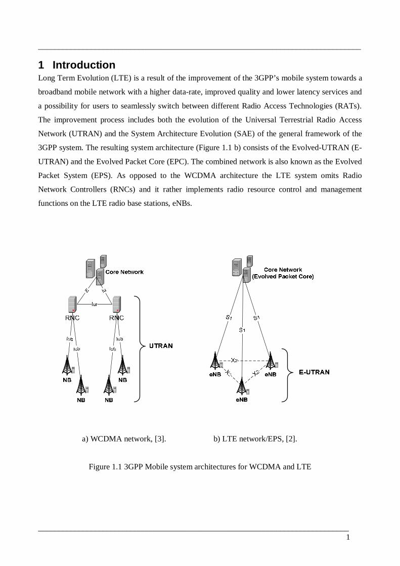
3GPP system. The resulting system architecture (Figure 1.1 b) consists of the EvolvedUTRAN (E
UTRAN) and the Evolved Packet Core (EPC). The combined network is also known as the Evolved
Packet System (EPS). As opposed to the WCDMA architecture the LTE system omits Radio
Network Controllers (RNCs) and it rather implements radio resource control and management
functions on the LTE radio base stations, eNBs.
a) WCDMA network, [3]. b) LTE network/EPS, [2].
Figure 1.1 3GPP Mobile system architectures for WCDMA and LTE

________________________________________________________________________________
_____________________________________________________________________________2
For improved performance over the air interface, LTE uses Orthogonal Frequency Division
Multiplexing (OFDM) technology for data transmission with improved transmission speed and
spectral efficiency [1]. Expected peak data rates are up to 100 Mbps in the downlink direction
within a 20 MHz spectrum allocation (spectral efficiency = 5 bps/Hz) and 50 Mbps in the uplink
direction with in a 20 MHz spectrum allocation (spectral efficiency = 2.5 bps/Hz) [9].
The high level service requirements and expectations of the LTE system are a direct reflection of
mobile data traffic growth recorded in the past few years. The mobile telecom industry has
witnessed a strong growth in the mobile broadband usage. According to the Global mobile
Suppliers Association (GSA) GSM/3GMarketUpdate for 2009, 409 million mobile broadband
subscriptions were reported for WCDMA and HSPA technologies. The report further states that
mobile broadband business is seen as profitable and growing. Hence data services provisioning has
become the main focus of the current mobile network operators. 3GPP’s Evolved Packet System
improvements are also targeting to meet this rapid growth in wireless IP data traffic. In addition to
the radio technology improvements the transport network connecting the EUTRAN with the EPC
should provide enough capacity and good service quality. Furthermore, it should enable cost
efficient network deployment and operation [5]. The trend is towards an all IP network to
interconnect the LTE radio access network and core networks as a faster and cost optimized
solution. The LTE eNBs have IP functionality to connect with the core network and with each other
through an IP backbone network.
Figure 1.2 WCDMA network
________________________________________________________________________________
_____________________________________________________________________________3
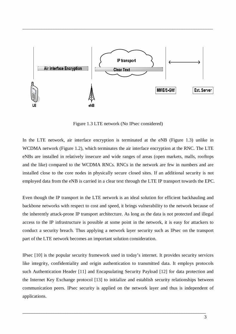
Figure 1.3 LTE network (No IPsec considered)
In the LTE network, air interface encryption is terminated at the eNB (Figure 1.3) unlike in
WCDMA network (Figure 1.2), which terminates the air interface encryption at the RNC. The LTE
eNBs are installed in relatively insecure and wide ranges of areas (open markets, malls, rooftops
and the like) compared to the WCDMA RNCs. RNCs in the network are few in numbers and are
installed close to the core nodes in physically secure closed sites. If an additional security is not
employed data from the eNB is carried in a clear text through the LTE IP transport towards the EPC.
Even though the IP transport in the LTE network is an ideal solution for efficient backhauling and
backbone networks with respect to cost and speed, it brings vulnerability to the network because of
the inherently attackprone IP transport architecture. As long as the data is not protected and illegal
access to the IP infrastructure is possible at some point in the network, it is easy for attackers to
conduct a security breach. Thus applying a network layer security such as IPsec on the transport
part of the LTE network becomes an important solution consideration.
IPsec [10] is the popular security framework used in today’s internet. It provides security services
like integrity, confidentiality and origin authentication to transmitted data. It employs protocols
such Authentication Header [11] and Encapsulating Security Payload [12] for data protection and
the Internet Key Exchange protocol [13] to initialize and establish security relationships between
communication peers. IPsec security is applied on the network layer and thus is independent of
applications.

________________________________________________________________________________
_____________________________________________________________________________4
1.1 ProblemThe 3GPP Evolved Packet system (EPS) is characterized by higherdata rate, lower latency, packet
optimized system that supports multiple Radio Access Technologies (RATs). Furthermore it should
also support enhanced QoS and high level of security features [5]. Particularly, the IPsec security
frame work is identified by 3GPP to be used in the LTE IP transport. However, given the strict data
rate and delay conditions for the LTE network, meeting the required level of security using IPsec
places a performance challenge in implementing the LTE network. Although IPsec is proposed as
the best solution for security over the LTE transport, implementing it does not come for free.
Additional headers and computational processes are introduced by IPsec protocols for data
encryption and peer authentication. IPsec implementation affects performance, transmission
efficiency, equipment cost, latency, and delay aspects of a network. The effect on transmission
efficiency is critical in mobile data networks as mobile data traffic is characterized by small sized
packets when compared to fixed data networks. The headertopayload ratio in mobile networks is
very high resulting in reduction of overall transmission efficiency. For an acceptable network
performance and a good level of security, a careful IPsec configuration and understanding should be
in place. Choosing among such available options involves careful implementation decisions to be
made. And for such decisions to be practical and valuable, studies and performance analysis of the
impacts of using IPsec become essential.
1.2 Objective and ScopeIn this thesis the impacts of IPsec implementation on the LTE transport are studied. The focus is on
3GPP proposed IPsec configurations for the LTE system. The analysis and results of this work are
useful for design choices of IPsec implementation and use in the LTE network.
The focus of this work is the implications of security solutions applied on the IP transport network
between the LTE radio access network (RAN) and the LTE evolved packet core (EPC). 3GPP data
encryption employed over the air interface between the mobile user equipment (UE) and the eNB is
not discussed in detail. An endtoend IPsec deployment scheme starting from the UE is also
excluded.
1.3 Approach and MethodologyThis thesis work uses 3GPP’s documents on security architecture, standards, requirements and
proposed implementations for the LTE system as a basic starting point. It further makes use of

________________________________________________________________________________
_____________________________________________________________________________5
measurement results from an endtoend connectivity test between Nokia Siemens Networks LTE
eNB and Cisco Wireless Security Gateway (WSG). Target test cases include:
Quality of Service,
Interoperability between IPsec implementations of the two equipments,
Throughput/Latency measurements,
Frame Loss Rate measurements and,
Packet fragmentation and reassembly impacts on performance.
IETF standardization documents (RFCs) are also frequently consulted for better understanding and
analysis of working IPsec implementations during laboratory tests. Technical papers and journals
on related topic are discussed in some parts of the thesis to make use of their findings and
sometimes make comparisons with alternative IPsec implementation options.
1.4 Thesis StructureThe second chapter gives an overview on the LTE/SAE system architecture and evolution. In
chapter three and four threats and security in the LTE transport are discussed. Chapter five
discusses IPsec security frame work and its use in the LTE system. Impacted aspects of the LTE
system due to IPsec implementation are presented in chapter six. The test setup and results are
discussed in chapter seven and eight respectively. Finally, chapter nine contains the conclusion and
proposals for future study items.

________________________________________________________________________________
_____________________________________________________________________________6
2 3GPP LTE/SAE System Overview
2.1 Long Term Evolution (LTE)The Long Term Evolution (LTE), initiated in 2004, is 3GPP’s continuous effort in improving and
optimizing 3GPP’s Universal Terrestrial Radio Access (UTRA) architecture [28]. It aims to keep
3G mobile networks competitive in the industry with respect to capacity, service speed and overall
ownership and operational costs. Driven by the fast growing mobile data traffic and the introduction
of new mobile broadband services such as video/audio streaming and online gaming, LTE is also
part of the process of evolving mobile networks in to future 4G networks. LTE radio access
network is called Evolved Universal Terrestrial Radio Access Network (EUTRAN).
High level requirements set for the EUTRAN include [28]:
Reduced cost per bit
Improved service provisioning – more services at lower cost with better user experience
Flexibility of use of existing and new frequency bands
Simplified architecture, Open interfaces
Allow for reasonable terminal power consumption
2.2 System Architecture Evolution (SAE)Alongside the LTE work to enhance the 3GPP radio access, System Architecture Evolution (SAE)
develops the framework for the evolution of the overall 3GPP system towards a higherdatarate,
lowerlatency and packetswitched system supporting multiple Radio Access Technologies (RATs)
[28]. 3GPP SAE examines the overall functioning of the 3GPP evolved system architecture
including the interworking of the LTE core network, the Evolved Packet Core (EPC), with the E
UTRAN.
2.3 3GPP Evolved Packet System (EPS)The 3GPP Evolved Packet System (EPS) refers to the overall evolved 3GPP mobile system
including the radio access and core networks. Unlike previous 3G networks the EPS is a completely
packet switched mobile network. The EPS architecture is a combination of the EUTRAN and the
Evolved Packet Core (EPC) shown in Figure 2.1. The EUTRAN consists of a set of evolved radio
base stations called evolved NodeB, eNBs. The EPC is comprised of control, management and
trafficforwarding network elements such as the Mobility Management Entity (MME) and the User
Plane Entity (UPE). The EUTRAN is connected to the EPC through the S1 interface. Neighboring
eNBs are interconnected through the X2 interface within the EUTRAN. EPS network elements are
________________________________________________________________________________
_____________________________________________________________________________7
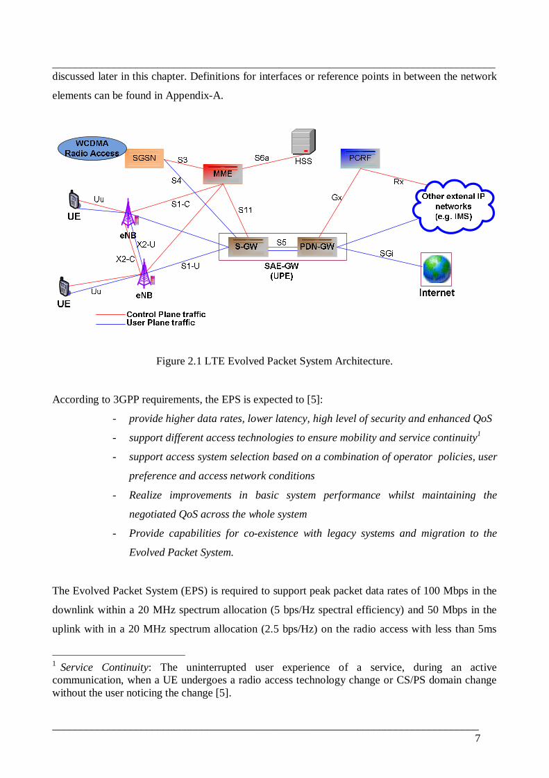
discussed later in this chapter. Definitions for interfaces or reference points in between the network
elements can be found in AppendixA.
Figure 2.1 LTE Evolved Packet System Architecture.
According to 3GPP requirements, the EPS is expected to [5]:
provide higher data rates, lower latency, high level of security and enhanced QoS
support different access technologies to ensure mobility and service continuity1
support access system selection based on a combination of operator policies, user
preference and access network conditions
Realize improvements in basic system performance whilst maintaining the
negotiated QoS across the whole system
Provide capabilities for coexistence with legacy systems and migration to the
Evolved Packet System.
The Evolved Packet System (EPS) is required to support peak packet data rates of 100 Mbps in the
downlink within a 20 MHz spectrum allocation (5 bps/Hz spectral efficiency) and 50 Mbps in the
uplink with in a 20 MHz spectrum allocation (2.5 bps/Hz) on the radio access with less than 5ms
1 Service Continuity: The uninterrupted user experience of a service, during an activecommunication, when a UE undergoes a radio access technology change or CS/PS domain changewithout the user noticing the change [5].
________________________________________________________________________________
_____________________________________________________________________________8
user and control plane latency [29]. It is further required by 3GPP that it has high capacity for voice,
data, and multimedia traffic. Costefficient deployment and operation of the network are also
additional 3GPP’s aspects set for the Evolved Packet System with optimal system complexity and
mobility management signaling [5].
2.4 Functional Elements of the EPSEvolved NodeB, eNB
The eNB is the only network element in the EUTRAN [2]. Its main functions include Radio
Resource Management and Control, allocation of resources to UEs and user plane traffic forwarding
to the serving gateway. It also performs IP header compression and encryption functions by Packet
Data Convergence Protocol (PDCP) protocol.
Mobility Management Entity, MME
The MME is the LTE core network element that mainly performs control functions such as UE
mobility management, UE authentication and authorization, NAS signaling termination and security
and roaming [30]. It also connects with exiting 3G networks for control signaling for mobility
between 3GPP access networks.
SAEGW
SAEGW is functional part of the LTE core that handles the user plane traffic. It is also known as
the User Plane Entity (UPE) and consists of the serving gateway (SGW) and the packet data
network gateway (PDNGW).
Serving Gateway, SGW
The serving gateway is the LTE core element, which is a logical part of the SAEGW, which
performs user data routing and forwarding functions. It is also the mobility anchor point for inter
eNB handover and inter3GPP mobility [30]. For lawful interception, it performs replication of user
traffic [25]. The SGW is implemented either as a standalone physical element or in combination
with the PDNGW to make up the SAEGW.
Packet Data Network Gateway, PDNGW
PDNGW is another logical part of the SAEGW which functions as the connection point to
external IP networks such as internet or IMS [30]. Other functions include peruser based packet
filtering and screening, lawful interception and accounting for interoperator charging,

________________________________________________________________________________
_____________________________________________________________________________9
Serving GPRS Support Node, SGSN
In the EPS context SGSN functions include inter EPC signaling mobility between 2G/3G and LTE
access networks, PDN and SGW selection and MME selection for handover to EUTRAN.
Policy Control and Charging Rules Function, PCRF
The PCRF provides network control regarding the service data flow detection, gating, QoS and
flowbased charging [31]. It is the termination point for Rx and Gx reference points.
Home Subscriber Server, HSS
HSS is the HLR equivalent database server which stores user related contexts and services. In
combination with the MME it performs UE authentication and authorization [8, 32].
2.5 LTE Transport
The transport network interconnecting the EUTRAN with the EPC is also expected to keep up with
the improvements in the LTE radio access with respect to data rate, performance and quality.
Particularly the highly growing volume of data traffic in mobile networks should be addressed by
an efficient and high capacity transport infrastructure. The widely existing legacy networks based
on TDM transport do not scale well in next generation mobile networks, which are characterized by
high capacity radio access networks. It is further required by the 3GPP standardizations that the
LTE transport should enable cost efficient network deployment and operation [5]. The trend is
towards the all IP network to interconnect the LTE radio access network and core networks as a
faster and costoptimized solution. The LTE eNBs have IP functionality to connect with the core
network and with each other through an IP backbone network.
Moving to an all IP scheme for backhauling and backbone networks in the LTE system clearly
brings efficiency and capacity benefits. However it also comes with the common IP protocol
security vulnerabilities. As long as the data is not protected and illegal access to the IP
infrastructure is possible at some point in the network, it would be easy for attackers to conduct a
security breach. Therefore a proper security framework should also be applied. The following two
chapters discuss the security threats and 3GPP proposed security solutions for the LTE transport.
________________________________________________________________________________
_____________________________________________________________________________10
3 Threats in the LTE SystemThis chapter discusses security threats on the LTE system, and their respective solutions, as
identified by 3GPP in [7] when eNBs or network nodes in the IP transport or core network elements
of the LTE network are compromised. More emphasis is given to attacks on the transport part of the
LTE system interconnecting the eNBs and the Evolved Packet Core (EPC) rather than the radio
access network. Possible attacks on the radio part of the system, such as UE tracking and IMSI
catching, are not discussed here. Air interface security, applied between the UE and eNB, is used to
address those security problems while transport security, applied between eNB and EPC addresses
threats related to the LTE transport.
Attacks on the LTE transport are based on the presence of vulnerabilities that lead to unauthorized
access to network nodes along the LTE transport path. Such vulnerabilities are the result the
following design considerations of the LTE system architecture [7].
small and costoptimized eNBs
Physically insecure eNB installation sites
Vulnerable IP transport infrastructure to interconnect eNBs to the EPC
An attacker can for example make use of a physically insecure eNB to steal security keys and
digital certificates as well as get hold of unencrypted user plane or control plane traffic. The eNB
works as a security termination point for encryption in both directions of data transfer, i.e. air
interface and IP transport. Thus we have two security tunnels working in such a way that one tunnel
transfers clear data to the other at their junction point. If we consider upstream traffic, going from
UE to EPC, there is a point in the eNB where radio protocols decrypt this traffic data before the IP
transport protocols take over the data and apply encryption to later send it to the core. The same
analysis also applies to downstream traffic. Therefore depending on the software implementation in
the eNB it is possible for an attacker to exploit this security hole for illegal actions.
The following security threats are identified and their respective solutions are proposed by 3GPP in
[7]. However they are restructured here to emphasize the security threats on different traffic types
such as control plane, user plane and management plane. The sensitivity of these traffic types is
different. Control plane and management plane traffic types are considered very sensitive and 3GPP
requirements for the LTE security mandate that security must be applied to these traffic categories.
User plane traffic security is recommended but it is left optional [8].

________________________________________________________________________________
_____________________________________________________________________________11
3.1 Threats to Control Plane (CP) TrafficThreat CP1 – Fake signaling messages from Radio Access Network (RAN) towards MME
DoS attack against MME.
Attacker uses compromised network nodes (eNB) or uses own device that mimics a network
node (eNB)
Solution:
Provide integrity protection for signaling messages
Use of cookies
Protocols used before the user is successfully authenticated should not be highly vulnerable
to (D)DoS attacks.
Threat CP2 – Eavesdropping to mobility management control plane traffic
Disclose sensitive data about users or network operators
Get hold of system information by tapping and studying mobility traffic
Solution:
Provide confidentiality protection to control plane traffic through encryption
Threat CP3 – Utilizing a compromised security/encryption termination point while encryption of
CP traffic is in place
eNB terminates both air interface and transport encryption/security pipes
Potential point for stealing keys or eavesdropping unprotected control plane traffic
Solution:
Physical protection for eNB
Authenticated and authorized access to nodes (eNBs)
Monitoring and detection capabilities
Threat CP4 – Modification of unprotected control plane (CP) data
Replay attacks
Modification of mobility management control data
Solution:
Confidentiality protection through encryption
Using signatures to guarantee integrity of data against modification
Time stamping and packet counting against replay attacks
________________________________________________________________________________
_____________________________________________________________________________12
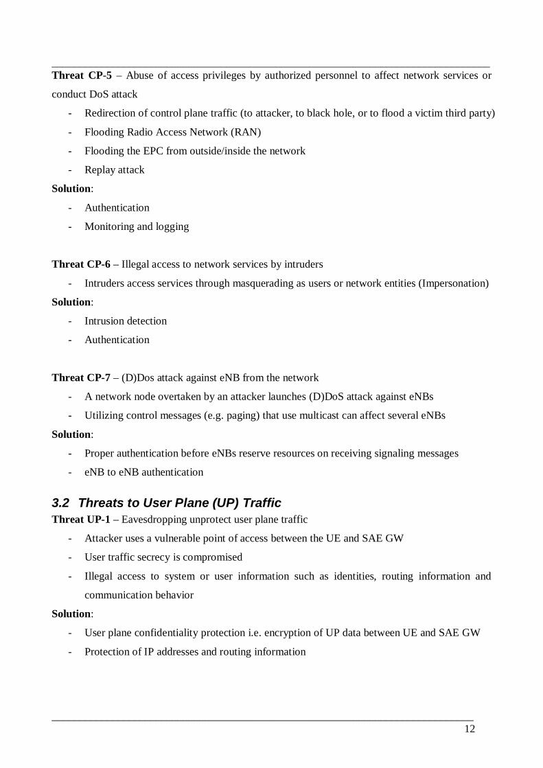
Threat CP5 – Abuse of access privileges by authorized personnel to affect network services or
conduct DoS attack
Redirection of control plane traffic (to attacker, to black hole, or to flood a victim third party)
Flooding Radio Access Network (RAN)
Flooding the EPC from outside/inside the network
Replay attack
Solution:
Authentication
Monitoring and logging
Threat CP6 – Illegal access to network services by intruders
Intruders access services through masquerading as users or network entities (Impersonation)
Solution:
Intrusion detection
Authentication
Threat CP7 – (D)Dos attack against eNB from the network
A network node overtaken by an attacker launches (D)DoS attack against eNBs
Utilizing control messages (e.g. paging) that use multicast can affect several eNBs
Solution:
Proper authentication before eNBs reserve resources on receiving signaling messages
eNB to eNB authentication
3.2 Threats to User Plane (UP) TrafficThreat UP1 – Eavesdropping unprotect user plane traffic
Attacker uses a vulnerable point of access between the UE and SAE GW
User traffic secrecy is compromised
Illegal access to system or user information such as identities, routing information and
communication behavior
Solution:
User plane confidentiality protection i.e. encryption of UP data between UE and SAE GW
Protection of IP addresses and routing information
________________________________________________________________________________
_____________________________________________________________________________13
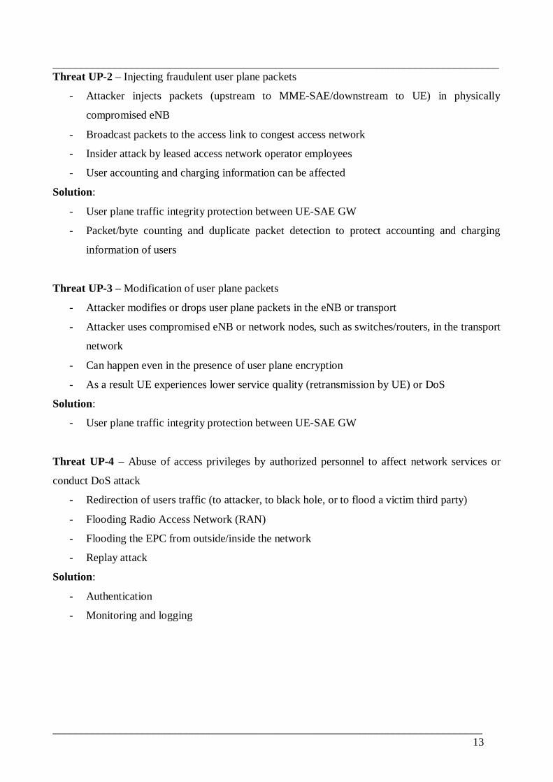
Threat UP2 – Injecting fraudulent user plane packets
Attacker injects packets (upstream to MMESAE/downstream to UE) in physically
compromised eNB
Broadcast packets to the access link to congest access network
Insider attack by leased access network operator employees
User accounting and charging information can be affected
Solution:
User plane traffic integrity protection between UESAE GW
Packet/byte counting and duplicate packet detection to protect accounting and charging
information of users
Threat UP3 – Modification of user plane packets
Attacker modifies or drops user plane packets in the eNB or transport
Attacker uses compromised eNB or network nodes, such as switches/routers, in the transport
network
Can happen even in the presence of user plane encryption
As a result UE experiences lower service quality (retransmission by UE) or DoS
Solution:
User plane traffic integrity protection between UESAE GW
Threat UP4 – Abuse of access privileges by authorized personnel to affect network services or
conduct DoS attack
Redirection of users traffic (to attacker, to black hole, or to flood a victim third party)
Flooding Radio Access Network (RAN)
Flooding the EPC from outside/inside the network
Replay attack
Solution:
Authentication
Monitoring and logging

________________________________________________________________________________
_____________________________________________________________________________14
3.3 Threats to Management Plane TrafficThreat MP1 – Access to O&M security context at the physically compromised eNB
Attacker breaks into eNB
Reconfigures the attacked eNB
Or use the attacked eNB to attack other eNBs
Solution:
physical security measures such as alarm systems to protect unauthorized opening of eNB
putting keys into a hard to break chips
3.4 SummaryThe LTE system design considerations to implement a flat network architecture using IP transport
between the insecure eNBs and the LTE core present several security threats. A proper security
should be deployed to protect sensitive data such as control and management traffic. Attackers with
access to a compromised eNB or other network nodes can eavesdrop or modify traffic data or
generate fake signaling messages creating DoS attack against core elements such as the MME. By
providing integrity and confidentiality protection to control and management traffic by security
solutions such as IPsec it is possible to hinder such attacks against the system. IPsec allows the
eNBs and core network elements to be able to mutually authenticate each other and communicate
securely. Likewise, confidentiality protection to user plane traffic can prevent attackers from
eavesdropping user data. The next chapter discusses security in the LTE system as identified by
3GPP.

________________________________________________________________________________
_____________________________________________________________________________15
4 Security in the LTE SystemThe security solutions in the Evolved Packet System (EPS) are implemented based on two
important concepts identified by the 3GPP. Looking in to these two security schemes is a good
starting point to understand the overall security in the LTE system.
• The Layered Security Approach and,
• Network Domain Security (NDS/IP).
4.1 Layered Security in the LTE SystemThe LTE system has two layers of security giving two security perimeters (Figure 4.1) [7]. The first
security layer is applied in EUTRAN, between the user equipment (UE) and eNB. This security
layer provides protection to Radio Resource Control1 (RRC) signaling and User Plane (UP) traffic
in the air interface. The second layer is between the UE and the Evolved Packet Core (EPC). This
layer provides protection to NonAccess Stratum2 (NAS) signaling messages between the UE and
MME. The advantage of this approach is that if security at the first layer (EUTRAN) is broken it
will have minimized effect on the second layer [7].
Figure 4.1 Layered Security in the LTE network (from [7])
1 RRC signaling messages carry radio system information such as cell level measurements and user context duringhandovers [25].2 NAS signaling exists between the UE and the MME. It is used for exchanging control information such as mutualauthentication and mobility management [25].
UE
eNB
eNB
Xu
Xu
MMES1C
S1CX2Evolved Packet Core
(EPC)
EUTRAN
SAE GW
S1U
S1U
Security layer1 Security layer2
Security layer1

________________________________________________________________________________
_____________________________________________________________________________16
4.2 Network Domain Security (NDS/IP)3GPP Network Domain Security (NDS/IP) specified in [6] is the network layer security provided to
IP based protocols and interfaces of 3G networks. 3GPP NDS/IP architecture is shown in Figure 4.2.
It divides the network in to separate security domains which are networks that are managed by a
single administrative authority [6]. Security domains are protected by security gateways (SEGs) at
their borders, i.e. Za interface as shown in the figure [6]. Internet Protocol security framework
(IPsec, [10]) for data protection and Internet Key Exchange (IKE, [13]) for key management are
identified to be used in NDS/IP.
Za
Zb
Zb
Zb
SEGA
Securitydomain A
Securitydomain B
SEGB
NEA1
NEA2
Zb
Zb
Zb
NEB1
NEB2
IKE "connection"
ESP Security Association
Figure 4.2 3GPP Network Domain Security NDS/IP Architecture, (from [6])
4.2.1 IPsec Profiling in NDS/IPEncapsulating Security Protocol (ESP) in tunnel mode is supported for IPsec applied between
security domains at the Za interface [6]. Transport mode can be used within a security domain at the

________________________________________________________________________________
_____________________________________________________________________________17
Zb interface [6]. ESP at the Za interface is used with mandatory data origin authentication and
integrity but optional confidentiality protection. IPsec and IKE are discussed in detail in the next
chapter. The security services supported by NDS/IP are [6]:
• Data integrity,
• Data origin authentication,
• Antireplay protection,
• Confidentiality (optional) and,
• Limited protection against traffic flow analysis when confidentiality is used.
4.2.2 Security Gateway (SEG)Network Domain Security (NDS/IP) as applied to the LTE network security architecture identifies
the use of security gateways with one of the following options [7].
• Aggregate all links from nodes which reside in one trusted core site in to a standalone
security gateway
• Aggregate all links from several eNBs which reside in a trusted network domain in to a
standalone security gateway (not usually the case for radio sites)
• Integrate IPsec functionality into each eNB located in physically not trusted sites
Two possible configurations following the points stated above are shown in Figure 4.3.a and 4.3.b.
3GPP recommended configuration is to integrate IPsec functionality into the eNBs. Each radio site
establishes security associations with a security gateway situated at the Evolved Packet Core of the
LTE network [7].
Figure 4.3.a Standalone SEG for several eNBs residing in a trusted area (not the usual case)
________________________________________________________________________________
_____________________________________________________________________________18
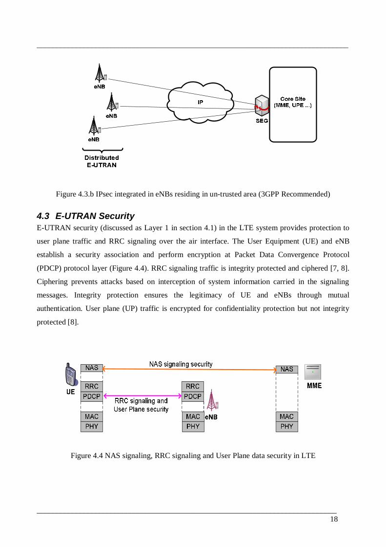
Figure 4.3.b IPsec integrated in eNBs residing in untrusted area (3GPP Recommended)
4.3 EUTRAN SecurityEUTRAN security (discussed as Layer 1 in section 4.1) in the LTE system provides protection to
user plane traffic and RRC signaling over the air interface. The User Equipment (UE) and eNB
establish a security association and perform encryption at Packet Data Convergence Protocol
(PDCP) protocol layer (Figure 4.4). RRC signaling traffic is integrity protected and ciphered [7, 8].
Ciphering prevents attacks based on interception of system information carried in the signaling
messages. Integrity protection ensures the legitimacy of UE and eNBs through mutual
authentication. User plane (UP) traffic is encrypted for confidentiality protection but not integrity
protected [8].
Figure 4.4 NAS signaling, RRC signaling and User Plane data security in LTE

________________________________________________________________________________
_____________________________________________________________________________19
4.4 NAS Signaling SecurityNonAccess Stratum Signaling (NAS) protocol is used for exchanging control messages between
the User Equipment (UE) and the Mobility Management Entity (MME). These control messages are
UE context information related to network attach, mobility management and authentication of the
user [25]. UE and MME establish a security association to protect NAS signaling messages by NAS
protocol (Figure 4.4 above). NAS signaling messages are integrity as well as confidentiality
protected [8].
4.5 LTE Transport SecurityThe introduction of IP to interconnect the LTE core network (EPC) with the LTE radio access
network (EUTRAN) brings security vulnerabilities. Any one with a malicious intent and access to
the IP transport or any of the radio sites can attack all IP reachable nodes (eNBs, MME or UPE) in
the network. The 3GPP service requirements for the EPS states the system shall ensure that
unauthorized users cannot obtain a legitimate IP address that can be used to establish
communication or enable malicious attacks on the evolved system entities [5]. NDS/IP security is
applied to provide protection mainly to control and management traffic within the EUTRAN
(between eNBs over the X2 interface) as well as between the EUTRAN and the EPC over the S1
interface [7].
4.5.1 Control and Management Plane trafficControl plane information, such as mobility management and authentication messages, and
management plane traffic, e.g. setup and configuration data for eNBs, are considered critical and
thus are strictly required to be protected [8]. 3GPP SAE security architecture [8] mandates that S1
and X2 control and management plane data be cryptographically protected. Tunnel mode IPsec ESP
[12] with IKEv2 is implemented on the eNBs and an IPsec termination node at the core end, which
could be the EPC nodes or a security gateway, SEG.
4.5.2 User Plane trafficThe 3GPP SAE security architecture specifies confidentiality as well as integrity protection to be
supported for user plane traffic in the LTE transport (S1U and X2U interfaces) [8]. However
cryptographic protection is left as an operator decision. In case insecure IP transport is used at these
interfaces, the IPsec ESP protocol in tunnel mode as in NDS/IP is used. IPsec transport mode is left
as an optional implementation in case of a need to reduce performance impacts of overhead,
particularly for small sized user data [7].
________________________________________________________________________________
_____________________________________________________________________________20
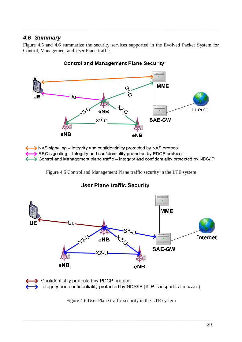
4.6 SummaryFigure 4.5 and 4.6 summarize the security services supported in the Evolved Packet System forControl, Management and User Plane traffic.
Figure 4.5 Control and Management Plane traffic security in the LTE system
Figure 4.6 User Plane traffic security in the LTE system
________________________________________________________________________________
_____________________________________________________________________________21
5 IPsec in the LTE SystemIPsec is designed to provide interoperable, high quality, cryptographicallybased security for IPv4
and IPv6. The set of security services offered includes access control, connectionless integrity, data
origin authentication, detection and rejection of replays (a form of partial sequence integrity),
confidentiality (via encryption), and limited traffic flow confidentiality. These services are provided
at the IP layer, offering protection in a standard fashion for all protocols that may be carried over
IP (including IP itself) [10].
Most of the security services are provided through use of two traffic security protocols, the
authentication Header (AH) and the Encapsulating Security Payload (ESP), and through the use of
cryptographic key management procedures and protocols [10].
The IETF defined IPsec security framework is proposed to be used at the LTE IP transport system
[7]. The principal advantage of using IPsec is that it works at the network layer and thus provides
application independent protection for all IP traffic. Furthermore the complexity and magnitude of
key negotiations required is significantly less when compared to higher layer security techniques.
Considering IPsec as the largely accepted network layer security framework for LTE networks, two
ways of implementation come in to view.
1. Endtoend IPsec implementation (Figure 5.1)
2. IPsec on the IP transport only (Figure 5.2)
In the first case IPsec security will have to be implemented at the IP layer between the user
equipment, UE and external server as the IPsec peers (Figure 5.1). This would require mobile
terminals to support IPsec features to be able to encrypt and decrypt application data. It would have
a significant performance impact on these equipments, especially on mobile phones used for
internet data services. There would also be countless number of security associations and
negotiations between every user and corresponding servers traversing the air interface. Additional
headers will also be introduced by IPsec protocols. Consequently efficient utilization of the scarce
air interface resources would greatly be affected. Furthermore, the endtoend IPsec deployment
scheme will have an extra encryption on the air interface since air interface encryption is already
present between the UE and eNB (Figure 5.1).

________________________________________________________________________________
_____________________________________________________________________________22
Figure 5.1 Endtoend IPsec Deployment Scheme
Figure 5.2 IPsec Deployment on the LTE IP Transport
Xenakis & Merakos proposed IPsec use for an endtoend deployment over UMTS network [17].
They conducted a performance analysis showing that data protection will increase required
bandwidth and security transformations will reduce performance of the light weight user devices.
According to their simulation results the endtoend security model is feasible for mobile terminal
processing capabilities exceeding 300 MIPS and for mean packet sizes greater than 480 bytes.
In the second case, shown in Figure 5.2, the use of IPsec VPNs is limited between eNBs and a
terminating node at a core site, e.g. security gateway. With a separate air interface security in place,
this second case is a better option to implement IPsec in the LTE network. It will avoid the burden
of supporting IPsec features in mobile equipments which normally have low processing power.
Looking into the structure of the protocol stack in all involved nodes in the LTE evolved packet
system (Figure 5.8), it can also be seen that IP packets from end users are further encapsulated by
the GPRS Tunneling Protocol then an additional transport IP at the eNB. Thus Implementing IPsec

________________________________________________________________________________
_____________________________________________________________________________23
using the eNB as one terminating point at the LTE radio access and a security gateway at the LTE
core as another is possible and will avoid the limitations of the endtoend security model.
5.1 IPsec Operating mode
5.1.1 Transport modeTransport mode is commonly used to provide endtoend security between two hosts which are the
actual communication end points as well as IPsec security peers. The communication end points are
the cryptographic endpoints [15].In IPv4 packets, IPsec protocol headers, AH or ESP, used in
transport mode are inserted after the IP header and options, and before the payload, i.e. upper layer
data as shown in Figure 5.4 (b) and 5.6 (b) [10]. In IPv6 Packets, the IPsec headers are inserted after
the IP header and some extension options, before or after destination options, and before the IP
payload [10].
According to the 3GPP NDS/IP security architecture , which proposes the use of security gateways
in between different security domains, IPsec transport mode is not recommend for use in the LTE
transport [6, 7]. However if it is deemed important the use of transport mode is allowed in between
network entities residing within a single security domain [6].
5.1.2 Tunnel modeA tunnel mode IPsec implementation uses a new IP header to encapsulate the whole of the original
IP packet in such a way that protection can be provided to the entire data and IP header fields. In
this mode the IPsec protocol headers, AH or ESP, are inserted after the new IP header and before
the original IP header as shown in Figure 5.4 (c) and 5.6 (c) [10]. Tunnel mode is suitable and most
widely used when a security deployment involves intermediate security gateways. It provides IPsec
security services by creating Virtual Private Networks (VPNs) over insecure wide area networks
such as the internet.
According to the 3GPP network domain security architecture [6, 7], IPsec tunnel mode is mandated
to be implemented in the LTE network at the S1 interface. This implies that no endtoend
encryption on a per user/application basis is provided. Packets are protected by IPsec only in
between the two ends, or termination points, of the tunnel. In the LTE system security architecture
these end points are the eNB in the EUTRAN and the security gateway (SEG) before the EPC,
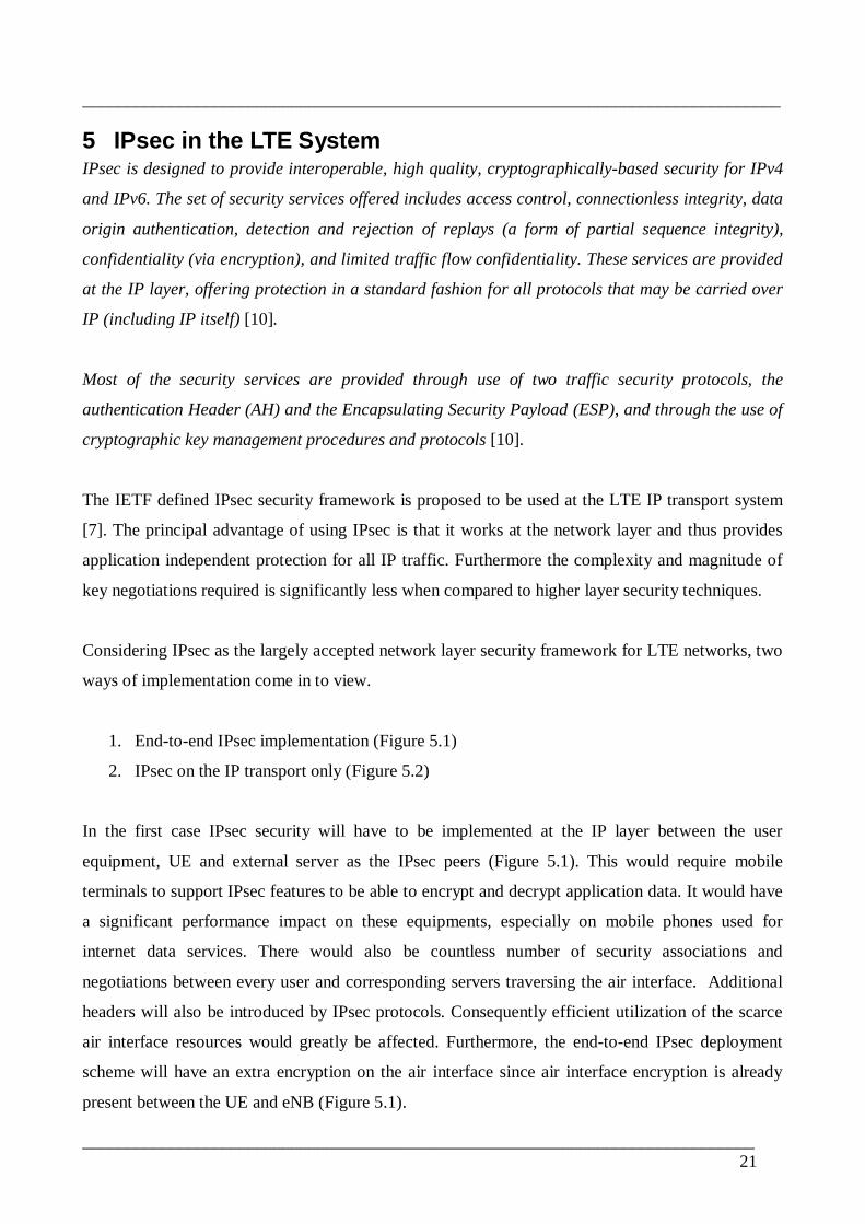
Evolved Packet Core (Figure 5.3).
________________________________________________________________________________
_____________________________________________________________________________24
Figure 5.3 IPsec tunnel in the LTE transport
5.2 IPsec ProtocolsCryptographic data protection in IPsec is provided by two protocols, Authentication Header (AH)
and Encapsulated Security Payload (ESP), implemented separately or together. Authentication
Header, IPsec AH [11], provides security features such as data integrity, data origin authentication
and antireplay protection. Encapsulating Security Payload, IPsec ESP [12], on the other hand can
additionally provide an optional data confidentiality protection and limited traffic flow protection.
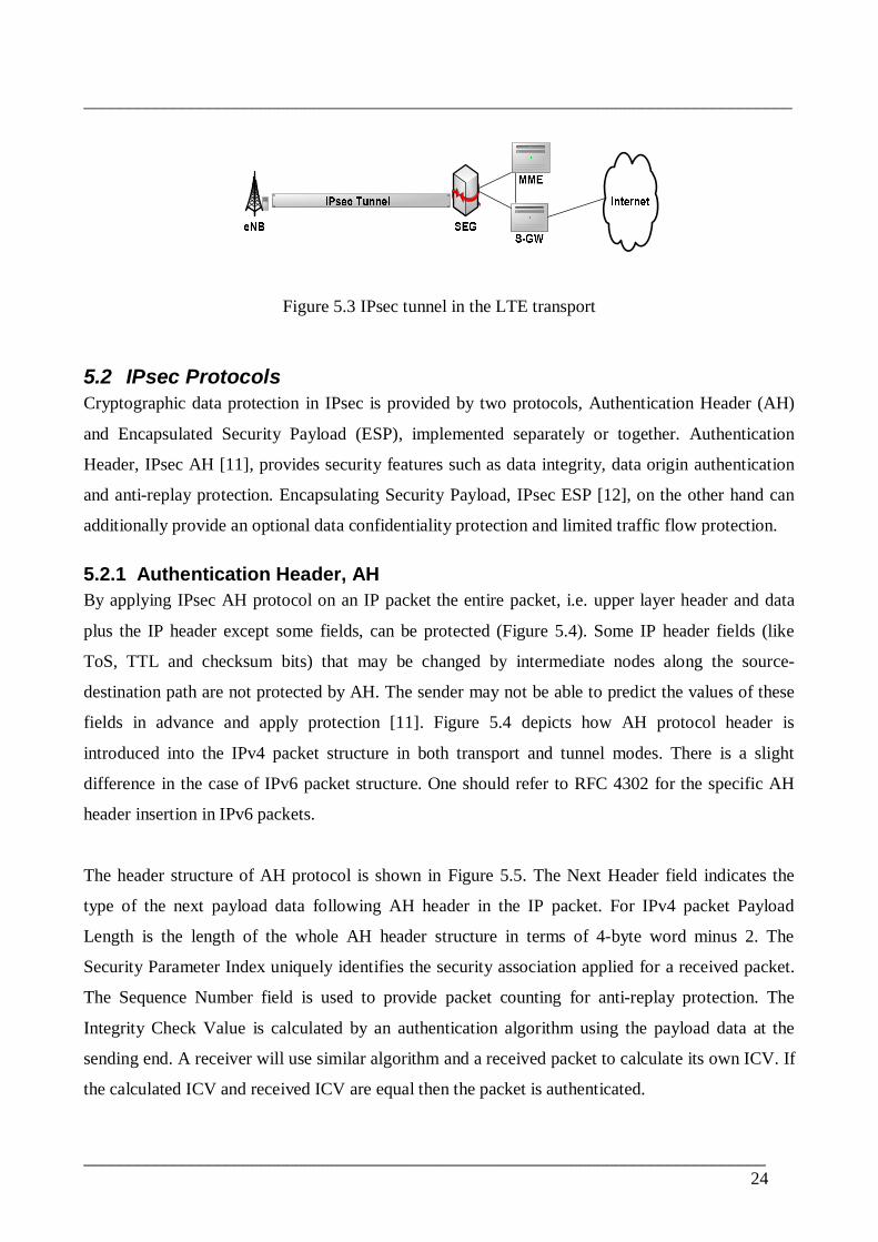
5.2.1 Authentication Header, AHBy applying IPsec AH protocol on an IP packet the entire packet, i.e. upper layer header and data
plus the IP header except some fields, can be protected (Figure 5.4). Some IP header fields (like
ToS, TTL and checksum bits) that may be changed by intermediate nodes along the source
destination path are not protected by AH. The sender may not be able to predict the values of these
fields in advance and apply protection [11]. Figure 5.4 depicts how AH protocol header is
introduced into the IPv4 packet structure in both transport and tunnel modes. There is a slight
difference in the case of IPv6 packet structure. One should refer to RFC 4302 for the specific AH
header insertion in IPv6 packets.
The header structure of AH protocol is shown in Figure 5.5. The Next Header field indicates the
type of the next payload data following AH header in the IP packet. For IPv4 packet Payload
Length is the length of the whole AH header structure in terms of 4byte word minus 2. The
Security Parameter Index uniquely identifies the security association applied for a received packet.
The Sequence Number field is used to provide packet counting for antireplay protection. The
Integrity Check Value is calculated by an authentication algorithm using the payload data at the
sending end. A receiver will use similar algorithm and a received packet to calculate its own ICV. If
the calculated ICV and received ICV are equal then the packet is authenticated.
________________________________________________________________________________
_____________________________________________________________________________25
(a) Original IP Packet
(b) IPsec AH in Transport Mode
(c) IPsec AH in Tunnel Mode
Figure 5.4 IPsec Authentication Header in IPv4 packet.
Figure 5.5 AH header structure [11]
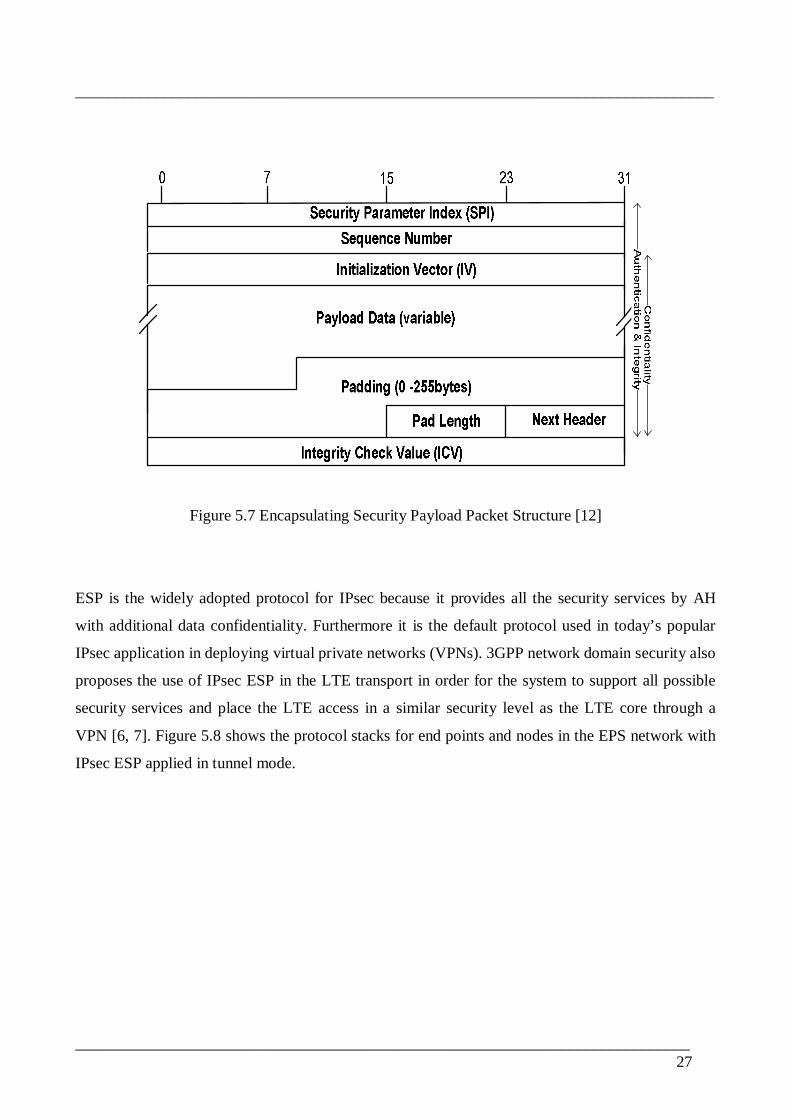
5.2.2 Encapsulating Security Payload, ESPEncapsulating Security Payload protocol protects only the payload part of an IP packet, i.e. upper
layer headers plus data [12]. Unlike AH, ESP does not provide protection to IP header fields (Figure
5.6). The figure depicts how ESP protocol header is introduced into the IPv4 packet structure. There
is a slight difference in the case of IPv6 packet structure. One should refer to RFC 4303 for the
specific ESP header insertion in IPv6 packet structure.

________________________________________________________________________________
_____________________________________________________________________________26
(a) Original IP Packet
(b) IPsec ESP in Transport Mode
(c) IPsec ESP in Tunnel Mode
Figure 5.6 IPsec Encapsulating Security Payload in IPv4 packet.
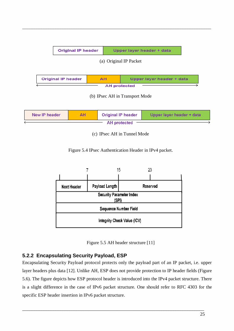
The header structure of ESP protocol is shown in Figure 5.7. Security Parameter Index uniquely
identifies the security association applied for a received packet. Sequence Number is used to
provide packet counting for antireplay protection. SPI field and the Sequence Number field make
up the ESP header. IV is unpredictable pseudo random number generated by the ESP
implementation [23, 6]. It is used as an initial input value by encryption transform algorithms
operating in cipher block chaining (CBC) mode. Padding fields are added to fulfill the requirement
of the 4 bytes block structure and encryption algorithms’ block size. Pad Length field contains the
length in bytes of the padding fields added. Next Header field indicates the type of the payload data
contained in the packet. The ESP trailer consists of possible padding fields, the Pad Length field
and the Next Header field. Integrity Check Value is calculated by an authentication algorithm using
the ESP header, payload data and the ESP trailer at the sending end. A receiver will use the same
algorithm and similar fields of a received packet to calculate its own ICV. If the calculated ICV and
received ICV are equal it means the packet is authenticated.
________________________________________________________________________________
_____________________________________________________________________________27
Figure 5.7 Encapsulating Security Payload Packet Structure [12]
ESP is the widely adopted protocol for IPsec because it provides all the security services by AH
with additional data confidentiality. Furthermore it is the default protocol used in today’s popular
IPsec application in deploying virtual private networks (VPNs). 3GPP network domain security also
proposes the use of IPsec ESP in the LTE transport in order for the system to support all possible
security services and place the LTE access in a similar security level as the LTE core through a
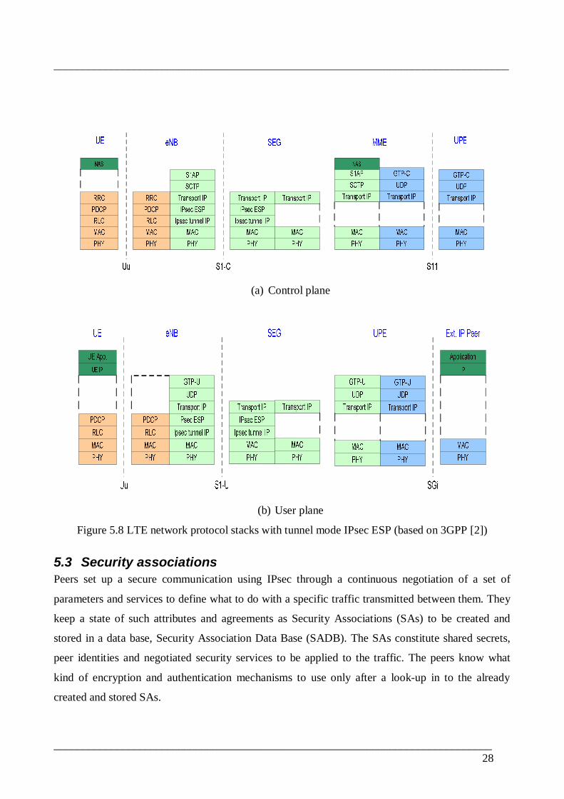
VPN [6, 7]. Figure 5.8 shows the protocol stacks for end points and nodes in the EPS network with
IPsec ESP applied in tunnel mode.
________________________________________________________________________________
_____________________________________________________________________________28
(a) Control plane
(b) User plane
Figure 5.8 LTE network protocol stacks with tunnel mode IPsec ESP (based on 3GPP [2])
5.3 Security associationsPeers set up a secure communication using IPsec through a continuous negotiation of a set of
parameters and services to define what to do with a specific traffic transmitted between them. They
keep a state of such attributes and agreements as Security Associations (SAs) to be created and
stored in a data base, Security Association Data Base (SADB). The SAs constitute shared secrets,
peer identities and negotiated security services to be applied to the traffic. The peers know what
kind of encryption and authentication mechanisms to use only after a lookup in to the already
created and stored SAs.

________________________________________________________________________________
_____________________________________________________________________________29
In IPsec different types of traffic can have different security services. Implementations can take
advantage of this feature to define what type of traffic to protect depending on the sensitivity of the
traffic flowing between security end points. This is defined as a security policy used to provide
traffic selection. A security policy associated with a given traffic, stated in a Security Policy
Database (SPD), will point to a specific SA in an SADB. Sometimes the traffic selection might lead
to a creation of new SA in case no existing entry is found in the SADB. In any case this SA, new or
old, will then be used to apply IPsec protection to the traffic going in and out of the peers.
Security Associations will be kept saved for use for as long as a secure communication is valid
between two peers. They can be used for all communications going on between the peers with in
their defined life time. The end points negotiate the life time of SAs in the beginning of the IPsec
set up process. It is important that the life time agreed is not too long to prevent an attack that could
possibly use the extended time to figure out secret information.
There are two kinds of security associations created during a complete IPsec set up: IKE SAs and
IPsec SAs. IKE SAs are created at the start of the secure communication when both peers have little
or no information about each other. They are used to securely exchange authentication information
and secret key materials used to create IPsec SAs which are then used to protect the actual data.
IKE SAs are bidirectional while IPsec SAs are unidirectional. For a single secure communication
one IKE SA and at least two IPsec SAs, for each direction, are required [13]. An IKE SA is
identified by initiator and responder cookies while an IPsec SA is identified by Security Parameter
Index (SPI), an IP destination address (ESP destination) and a security protocol identifier (ESP) [6].
In 3GPP Evolved Packet System (EPS) security associations are created between the core and the
eNB over the S1 interface and between adjacent eNBs via X2 interface [8].
5.4 Key managementFor a complete secure communication establishment IPsec operates in two major processes. First
process is the key management which is followed by the actual data protection process by IPsec
protocols, ESP and AH. The fundamental complexity in the IPsec security lies in the management
of secret keys. It deals with the creation, distribution and maintenance of keys and authentication of
peers. It helps produce keys and security agreements that are applied by the security protocols. The
objective is that communicating peers are able to generate secret key pairs without actually
transmitting the keys over insecure transport medium.
________________________________________________________________________________
_____________________________________________________________________________30
The strength of IPsec security framework greatly depends on a proper key management process. If
not designed carefully an attacker can easily exploit a small flaw in the creation and distribution of
keys that could jeopardize the overall security framework. There are two ways of key management
used in the creation and negotiation of keys: manual and automated [10].
5.4.1 Manual Key ManagementIn a manual key management process administrators will manually enter parameters that are used to
generate keys [14]. This requires manual work every time a new peer is added to the secured
network or an old key is to be replaced. Scalability becomes a critical design issue with this
mechanism as network size grows [10]. Manual key management is only suitable for small sized
networks otherwise becomes cumbersome or even vulnerable as it is likely that mistakes could be
made by operation and management personnel [14].
In a mobile packet network, such as the LTE system, this method is not a feasible solution as there
could be thousands of eNBs in a single network that need to have the secret keys to be entered to.
Manual key management does not scale for such big networks rather an automatic mechanism for
creating and refreshing keys should be considered.
5.4.2 Internet Key Exchange, IKEInternet Key Exchange (IKE, RFC4306) is the popular automatic key management used in the
internet. It is the default protocol in IPsec framework used to authenticate peers in addition to create
and maintain keys used in subsequent secure communications. It performs mutual authentication
between two parties and establishes an IKE security association (SA) that includes shared secret
information that can be used to efficiently establish SAs for Encapsulating Security Payload and/or
Authentication Header and a set of cryptographic algorithms to be used by the SAs to protect the
traffic that they carry [13].
Internet Key Exchange protocol for IPsec is built as a composite structure of three base protocols:
Internet Security Association and Key Management Protocol (ISAKMP), Oakley, and Secure Key
Exchange Mechanism (SKEME) [14].
IKE operates by exchanging messages between entities in a request/response format [13]. Initial
messages, six in IKEv1 and four in IKEv2, are used to negotiate and exchange cryptographic
algorithms, DiffieHellman groups and authentication information such as identities and certificates.

________________________________________________________________________________
_____________________________________________________________________________31
As a result of these exchanges an IKE SA is created which is in turn used to establish IPsec SAs for
the later actual protected data transfer.
In IKE, peer authentication is done either with preshared secrets or digitally signed certificates. If
preshared secrets are used, the shared secrets need to be entered to both peers. These secrets are
specific to the authenticated peers and are linked to their IP addresses. In the case of certificates a
third party trust point or a certificate authority (CA) is involved for certificate enrollment process
needed to digitally sign certificates. Authentication is done when the peers exchange their
certificates and verify the trusted third party digital signature. The peers obtain their certificates
through a separate mechanism, manually or automatically, which is not part of IPsec frame work.
For security associations between eNBs, 3GPP System Architecture Evolution identifies three key
management solutions for the Evolved Packet System security [7].
1) Using preshared secrets: which requires entering secret information to each eNB by
operation and management personnel.
2) Using digitally signed certificates: each eNB will have to obtain certificates signed by a
Certificate Authority (CA). Certificate revocation mechanisms and appropriate certificate
life time definitions should in place.
3) Using centralized node(s) in the network to generate eNBeNB security associations. The
centralized nodes need to keep a state of the network topology of the eNBs.
Using digital certificates is more secure and scalable option among the above solutions for the LTE
network.
5.4.3 IKEv1 vs. IKEv2: A ComparisonIKEv2 is a successor and an improvement for IKEv1. IKEv2 protocol is designed in a way that it is
advantageous with respect to simplicity, flexibility and performance as compared to IKEv1. Using
the National Institute of Technology VPN simulator NIIST, NIST IPsec and IKE Simulation Tool,
H. Soussi, et al. showed that IKEv2 creates less number of SAs for a given network compared to
IKEv1 [16]. They argue that this is due to the less complex and more flexible IKEv2 protocol unlike
that of IKEv1. They have also showed that IKEv2 keeps better and constant SA creation delay due
to less number of rekeying required.

________________________________________________________________________________
_____________________________________________________________________________32
3GPP specified IPsec use in the LTE system recommends the use of IKEv2 over IKEv1, while in
practical implementations the latter is supported as a fallback option in case of interoperability
issues for example. The following important improvements provided by the IKEv2 protocol are
main reasons for its 3GPP recommended use [7]:
Reduced number of IKE exchanges to establish IKE and child SAs
SA life time can be chosen independently by each endpoint
Flexibility in choosing traffic selectors
Better SA management: establish, manage and destroy
Better QoS handling: It is possible to create different SAs between the same peers.
SCTP multihoming can be supported
Built in support for NAT traversal
Less protocol and implementation complexity
5.5 SummaryAccording to 3GPP Network Domain Security (NDS/IP), IPsec protection for the LTE system is
applied only on the transport network, i.e. over S1 and X2 interfaces, interconnecting the radio
access and the LTE core site. IPsec ESP in tunnel mode is used in order to provide all the required
security services listed in chapter 4. Security Associations are established between eNBs and a
security gateway (SEG) placed at the LTE core. Such architecture implies that different eNBs
communicating with each other via the X2 interface must use the SEG as an intermediate node. The
Internet Key Exchange protocol is used to mutually authenticate the core SEG and the eNBs as well
as establish the SAs between them. IKEv2 is the 3GPP recommended protocol over IKEv1 even
though the later is also supported as an alternative implementation.

________________________________________________________________________________
_____________________________________________________________________________33
6 Impacts of IPsec in LTEApplying IPsec security protection to packets (control plane as well user plane) implies [7]:
additional requirement for the nodes to start processing on each packet passing through in
both directions, which in turn implies powerful hardware crypto chip resulting in higher
over all cost of the LTE system
increased packet processing times on the system, resulting in longer delays
increased complexity and large amount of Security Associations in the network, putting the
over all system performance in question
and so on.
Furthermore, 3GPP recommended IPsec deployment in the LTE system using a central security
gateway (SEG) at a core site (Figure 4.3.b) affects the network architecture. Every eNB establishes
security association with the central SEG forcing all traffic from all eNBs to traverse the core site.
Thus traffic between neighboring eNBs, connected with the X2 interface, is routed through a central
security gateway even though the actual routing distance between the two nodes is closer. This adds
extra delay and packet processing due to the longer distance as well as additional decryption and
encryption performed at the SEG.
Given the strict requirements for high quality, high data rate and low latency services for the LTE
system, implementing a powerful security framework like IPsec raises performance challenges. In
order to meet the high level service expectations of the LTE system together with improved security,
implementation decisions should be made wisely. The decisions should look in to such tradeoff
questions as:
which configuration options, in line with set standards, give the best possible performance
which part of the traffic is really sensitive and must be protected
which security service (confidentiality, integrity … ) to apply to which part of the traffic
how to distinguish between the different traffic packets
and so on
Some of the above decision issues can obviously be answered as some of them are also clearly
stated in the 3GPP standards. For example there is no question that the control and management
traffic should be protected with IPsec. But which IPsec protocol and mode is to be used depends on
________________________________________________________________________________
_____________________________________________________________________________34
which security service is negotiated to be applied. Other decisions could be easy to make after
performance test analysis and actual measurement results of tests are taken in to considerations.
It is important to consider such solutions as compression techniques in order to compensate for
additional header lengths by IPsec protocols. This is a critical issue in mobile networks because
most packets are of small size giving higher values of header to payload ratio. The efficiency of
transporting the actual information will be considerably low unless mechanisms such as datagram
compression are applied. In this chapter different impacts of IPsec implementation in the LTE
system are discussed.
6.1 Quality of ServiceITUT Recommendation E.800 defines QoS as [18]: “The collective effect of service performance
which determine the degree of satisfaction of a user of the service.”
The concept of QoS stems from the fact that all services do not need to utilize shared transmission
resources in exactly the same manner. Some services (e.g. conversational voice) require timely
delivery while accepting data losses. On the other hand some other services (e.g. web browsing, e
mail and file transfer) require reliable delivery with a little or no care for transmission delays. QoS
mechanisms differentiate services so as to provide more capacity for those services that really need
it for a proper functioning. Every other service will be treated with the remaining capacity as
normal. In case of sever overload rate limitation is imposed even on high priority traffic so as not to
totally starve other services.
There are two approaches used in order to achieve QoS in the internet:
Integrated Services (IntServ): In this approach a given bit rate is reserved for services along a
transmission path. Resource reservation Protocol (RSVP) is used by applications to communicate
reservations with all involved nodes along the sourcedestination path. IntServ is not specified by
the 3GPP standards for use in the LTE system.
Differentiated Services (DiffServ): In differentiated services concept packets are marked with
identifications to classify different traffic types. Intermediate nodes conduct inspection on the
header of every received packet in order to provide differentiation according to agreed upon priority
level assigned to each traffic type. DiffServ Code Point (DSCP) bits on the IP header are used to
mark packets and classify traffic types in IP networks [19]. DSCP bits correspond to IPv4 Type of

________________________________________________________________________________
_____________________________________________________________________________35
Service (ToS) and IPv6 Traffic Class fields. The DSCP values are mapped to respective Per Hop
Behaviors (PHBs) associated with each traffic type or service as specified in [21]. The PHB of a
service or traffic aggregate determines the kind of forwarding treatment it receives by routers along
the traffic path. The forwarding treatment in turn represents the kind of packet scheduling and
queuing that the packets are provided.
In 3GPP Evolved Packet System QoS differentiation is supported for different classes of traffic
corresponding to different services [5]. Each Service Data Flow (SDF) is identified by a scalar
value called QoS Class Identifier value (QCI). The QCI value is in turn related to performance
characteristics that govern the way each traffic packet is treated at every forwarding node along the
endtoend path from the UE to external Packet Data Network (PDN) [20]. The performance
characteristics include resource type, priority, packet delay budget and packet error loss rate [20].
The resource type specifies whether a GBR (Guaranteed Bit Rate) and NonGBR radio resource is
provided for the services. Standardized QCI values are mapped to these characteristics as shown in
Table 8.1 [20].
Example Services QCI RadioResource
Type
Priority PacketDelay
Budget
PacketError Loss
RateConversational Voice 1
GBR
2 100 ms 102
Conversational Video (LiveStreaming)
2 4 150 ms 103
Real Time Gaming 3 3 50 ms 103
NonConversational Video(Buffered Streaming)
4 5 300 ms 106
IMS Signaling 5
NonGBR
1 100 ms 106
Video (Buffered Streaming)TCPbased (e.g., www, email,chat, ftp, p2p file sharing,progressive video, etc.)
6 6300 ms 106
Voice,Video (Live Streaming)Interactive Gaming
7 7100 ms 103
Video (BufferedStreaming)TCPbased (e.g., www, email, chat, ftp, p2p filesharing, progressive video,etc.)
8 8
300 ms 106
9 9
Table 8.1.1 Standardized QCI characteristics [20]

________________________________________________________________________________
_____________________________________________________________________________36
The priority level associated with each QCI in Table 8.1.1 is used to define the sensitivity of the
services. IMS signaling has a priority 1 and a very low Packet Error Loss Rate (PELR). Thus is
expected to receive prioritized forwarding treatment. To ensure fast connection establishment
between the UE and PDN it is crucial that signaling and control plane traffic is neither dropped nor
delayed. Packet Delay Budget (PDB) values given in the table define upper bounds for a packet
delay between a UE and nodes in the EPC. Conversational voice has relatively higher PELR value
but strict delay requirement. This service tolerates packet losses but packets that make it to the
receiver are required to be delivered in time and in order.
To provide QoS differentiation according to the above performance characteristics, the QCI classes
are mapped to respective DSCP marking in the LTE IP transport. Thus the different traffic types
will receive prioritized packet scheduling and queuing treatments according to the relative Per Hop
Behaviors (PHB) associated with the DSCP values.
IPsec and QoS Management – DSCP copyingAs explained above QoS management to differentiate services using DiffServ mechanism works
with nodes along the traffic path performing a packet header inspection to identify the specific
forwarding treatment to be provided. In the LTE IP transport IPsec ESP in tunnel mode is applied to
the traffic, in which case the original packet headers are not visible for such header inspection by
the intermediate nodes. To mitigate this problem in IPsec VPN networks the inner DiffServ bits on
the original data IP header are required to be copied to the outer IPsec tunnel header [10]. The IPsec
terminating nodes in the LTE network, eNB and SEG, are responsible to do this copying during
IPsec tunnel IP header construction. Now that the DS field is visible again, each encrypted packet
will receive the required service differentiation as well.
QoS within IPsec Implementation – Differentiating IPsec traffic in advanceQoS differentiations concepts above are mainly focused on how to prioritize services so that
transmission capacity is fairly shared between them. In particular, how IPsec tunnel mode poses a
problem to the packet header inspection is discussed. Yet another issue of concern about QoS and
IPsec VPNs is the effective utilization of the processing capacity of IPsec terminating nodes. If no
QoS functionality is added to the IPsec implementations in these nodes and there is more IPsec
traffic to be processed than they can handle, extra traffic is dropped simply with a FirstInFirstOut
manner. However if a QoS functionality is introduced in to the IPsec packet processing, it will be

________________________________________________________________________________
_____________________________________________________________________________37
possible to differentiate and prioritize among services before IPsec is applied. This approach helps
to not only prioritize the IPsec processing among services but also avoids unnecessary consumption
of CPU time by the extensive IPsec protocols algorithms applied to low priority traffic.
Völker et al. propose an IPsec implementation (IPseCK) which incorporates QoS functionality to
the IPsec packet processing in order to provide such service differentiation [22]. Their study shows
that it is possible to effectively differentiate high priority IPsec packets before applying IPsec. In
such a way, only demanding services will receive prioritized IPsec protection during overload
situations. Völker et al. further claim that this approach provides an additional protection against
DoS attack targeting the IPsec processing nodes.
6.2 System PerformanceA tradeoff between system performance and data protection is one critical issue when employing
network security using IPsec. Adding security to a network comes with performance costs. Two
main performance aspects of a network that are affected due to IPsec security implementation are
throughput and latency. IPsec protected packets in a network go through an additional processing
by encryption and authentication algorithms resulting in reduced throughput and increased latency.
IPsec adds extra headers and converts clear text payload into cipher text reducing bandwidth
utilization and producing extra delay in the network.
The performance impacts of IPsec vary with the choices of security services for a given IPsec
deployment. Niedermayer et al. conducted a measurement study on IPsec performance using native
IPsec implementation of Linux 2.6.9 [34]. Their study showed that message authentication with AH
HMACSHA1 affects system performance more than encryption with ESP AESCBC. Obviously
choosing both authentication and encryption services together will affect performance to a larger
extent than employing only one of them. Therefore the choice of the security services should be
balanced with the acquired performance penalty. Combining can be done with AH for
authentication and ESP for encryption or using only ESP for both authentication and encryption.
Performance wise, the experiment by Niedermayer et al. indicated no significant difference. Unlike
ESP additional security advantage is gained by AH since some IP header fields are authenticated by
the later. However, using AH for traffic characterized by dominant small packets, e.g. real time
traffic, will have increased overhead making ESP the better option for both encryption and
authentication [34].

________________________________________________________________________________
_____________________________________________________________________________38
The choice of authentication/encryption algorithms is also an important factor that determines the
performance compromise against security. For authentication algorithms the result from the
research by Niedermayer et al. showed that HMACMD5 gives relatively less latency and higher
throughput than HMACSHA1 while for encryption algorithms AESCBC has less latency and
higher throughput than 3DESCBC [34]. Popular combination for authentication and encryption
algorithms nowadays, security strength and performance balanced, is using HMACSHA1 and
AESCBC respectively. System performance is affected less by MD5 than SHA1, but SHA1
provides better security.
Many other IPsec performance analysis studies have been conducted ever since. Gabriela’s work on
IPsec performance analysis in [35] showed that IPsec significantly affects performance for small
packets (64 to 500 bytes) and is considered unsuitable for delay sensitive data such as
synchronization traffic.
6.3 Packet Overhead3GPP Standard IPsec configuration in the LTE NetworkTable 6.3.1 summarizes standardized configuration of IPsec to be supported in the implementation
of LTE IP transport according to 3GPP NDS/IP [6, 7]. Additional headers introduced to data
packets by the standard IPsec profiling are stated in the right column next to the features causing the
overhead. IPsec tunnel mode uses a new IP header to encapsulate the whole of the original IP
packet. ESP header contains a 4 bytes Security Parameter Index field plus a 4 bytes Sequence
Number field as shown in Figure 6.3.1.
3GPP standardized IPsec
profile feature
Overhead
Operating mode Tunnel 20 bytes IP header
IPsec Protocol ESP 8 bytes header
Ciphering Transform AESCBC with 128 bit
Key
16 bytes IV plus Padding bytes.
Authentication Transform HMACSHA1 12 bytes Integrity Check Value.
Table 6.3.1 Standardized 3GPP IPsec Profiling
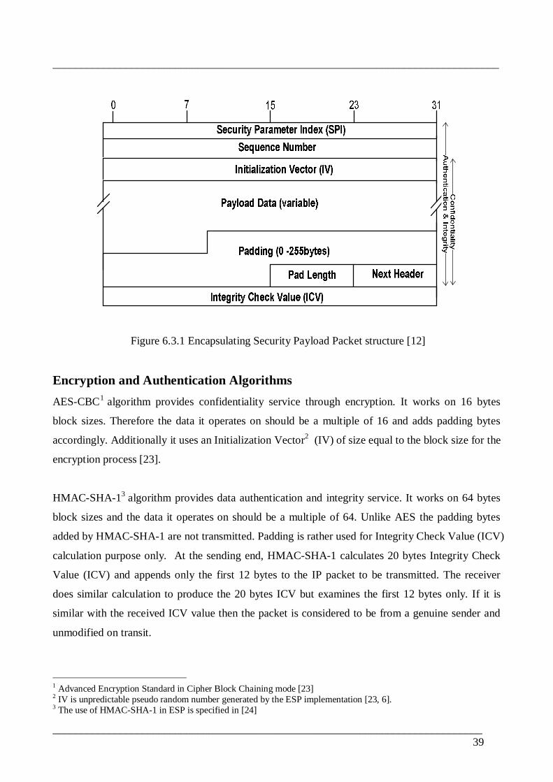
________________________________________________________________________________
_____________________________________________________________________________39
Figure 6.3.1 Encapsulating Security Payload Packet structure [12]
Encryption and Authentication AlgorithmsAESCBC1 algorithm provides confidentiality service through encryption. It works on 16 bytes
block sizes. Therefore the data it operates on should be a multiple of 16 and adds padding bytes
accordingly. Additionally it uses an Initialization Vector2 (IV) of size equal to the block size for the
encryption process [23].
HMACSHA13 algorithm provides data authentication and integrity service. It works on 64 bytes
block sizes and the data it operates on should be a multiple of 64. Unlike AES the padding bytes
added by HMACSHA1 are not transmitted. Padding is rather used for Integrity Check Value (ICV)
calculation purpose only. At the sending end, HMACSHA1 calculates 20 bytes Integrity Check
Value (ICV) and appends only the first 12 bytes to the IP packet to be transmitted. The receiver
does similar calculation to produce the 20 bytes ICV but examines the first 12 bytes only. If it is
similar with the received ICV value then the packet is considered to be from a genuine sender and
unmodified on transit.
1 Advanced Encryption Standard in Cipher Block Chaining mode [23]2 IV is unpredictable pseudo random number generated by the ESP implementation [23, 6].3 The use of HMACSHA1 in ESP is specified in [24]
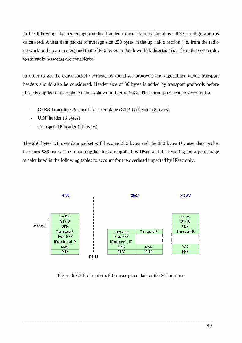
________________________________________________________________________________
_____________________________________________________________________________40
In the following, the percentage overhead added to user data by the above IPsec configuration is
calculated. A user data packet of average size 250 bytes in the up link direction (i.e. from the radio
network to the core nodes) and that of 850 bytes in the down link direction (i.e. from the core nodes
to the radio network) are considered.
In order to get the exact packet overhead by the IPsec protocols and algorithms, added transport
headers should also be considered. Header size of 36 bytes is added by transport protocols before
IPsec is applied to user plane data as shown in Figure 6.3.2. These transport headers account for:
GPRS Tunneling Protocol for User plane (GTPU) header (8 bytes)
UDP header (8 bytes)
Transport IP header (20 bytes)
The 250 bytes UL user data packet will become 286 bytes and the 850 bytes DL user data packet
becomes 886 bytes. The remaining headers are applied by IPsec and the resulting extra percentage
is calculated in the following tables to account for the overhead impacted by IPsec only.
Figure 6.3.2 Protocol stack for user plane data at the S1 interface

________________________________________________________________________________
_____________________________________________________________________________41
For 286 bytes of UL data packet an additional 2 bytes of padding is added by AESCBC. HMAC
SH1 further adds 12 bytes of ICV. The total extra header added to the packet becomes 58 bytes as
shown in Table 6.3.2. This means that 16.9% extra size is introduced by the given IPsec profile. In
other words the LTE transport dimensioning should consider an extra 16.9% upstream capacity
when IPsec is applied to the user plane traffic.
User plane packet in UL direction (Radio network to Core network withaverage size of 250 bytes plus 36 bytes transport header.)
Overhead(Bytes)
Outer IP header (tunnel mode) 20
ESP header (SPI + SN) 8
ESP encryption transform (AES_CBC) padding 2
ESP authentication transform (ESP_HMAC_SHA1) 12
ESP Initialization Vector (IV) 16
Total IPsec overhead 58Extra size introduced by IPsec (%) 16.9%
Table 6.3.2 Percentage overhead for UL user data (250 bytes)
For 886 bytes of DL data packet an additional 10 bytes of padding is added by AESCBC algorithm.
HMACSH1 further adds 12 bytes byes of ICV. The total extra header added to the packet data
becomes 66 bytes as illustrated in Table 6.3.3. There is 6.9% extra size is introduced and the LTE
transport dimensioning should consider an extra 6.9% downstream capacity when IPsec is applied
to the user plane traffic.

________________________________________________________________________________
_____________________________________________________________________________42
User plane packet in DL direction (Core network to Radio network withaverage size of 850 bytes plus 36 bytes transport header.)
Overhead(Bytes)
Outer IP header (tunnel mode) 20
ESP header (SPI + SN) 8
ESP encryption transform (AES_CBC) padding 10
ESP authentication transform (ESP_HMAC_SHA1) 12
ESP Initialization Vector (IV) 16
Total IPsec overhead 66Extra size introduced by IPsec (%) 6.9%
Table 6.3.3 Percentage overhead for DL user data (850 bytes)
Similar percentage IPsec packet overhead for a range of packet sizes is calculated (Table 6.3.4).
Results are also plotted as a graph shown in Figure 6.3.3.
Packet Size plus 36bytes Transport
overhead(Bytes)
IPsecPacket
SizeOverhead
PercentageOverhead
(%)
Packet Size plus 36bytes Transport
overhead(Bytes)
IPsecPacket
SizeOverhead
PercentageOverhead
(%)40 64 61.54 500 68 11.9750 70 58.33 600 64 9.6460 60 50.00 700 60 7.8970 66 48.53 800 72 8.2680 72 47.37 900 68 7.0290 62 40.79 1000 64 6.02
100 68 40.48 1100 60 5.17150 66 30.56 1200 72 5.66200 64 24.24 1300 68 4.97300 60 16.67 1400 64 4.37400 72 15.25 1500 60 3.85
Table 6.3.4 IPsec packet size overhead for the LTE transport
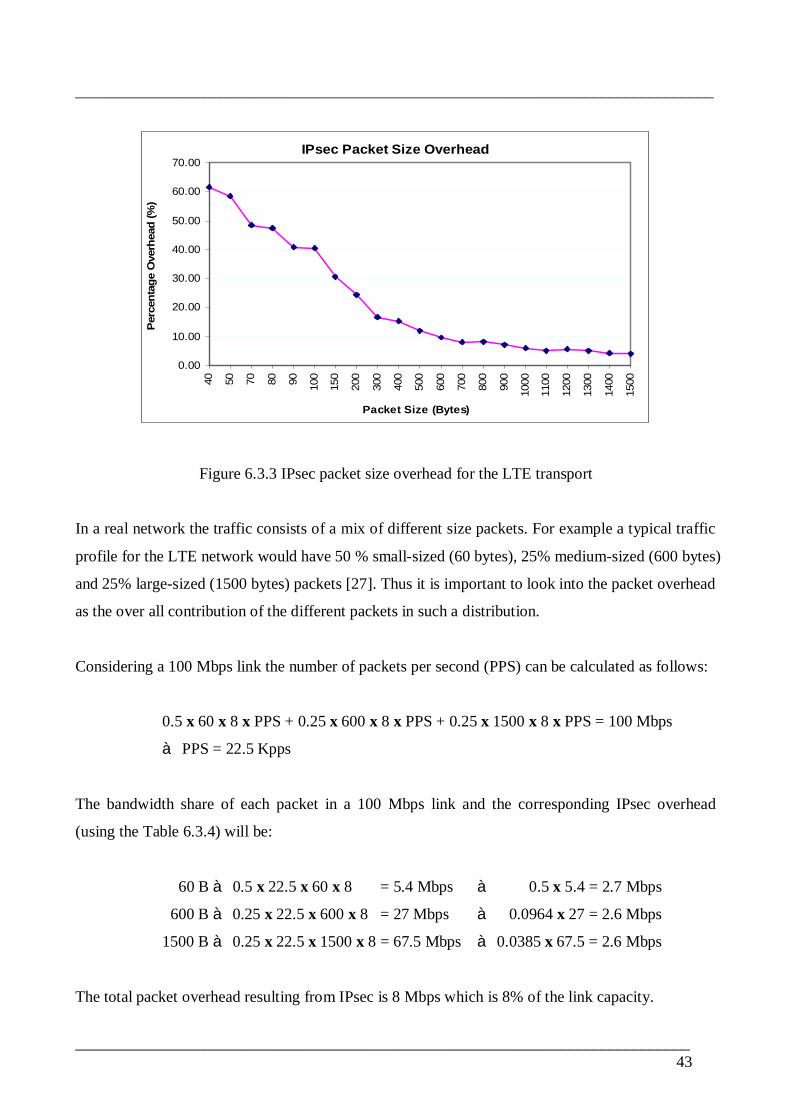
________________________________________________________________________________
_____________________________________________________________________________43
IPsec Packet Size Overhead
0.00
10.00
20.00
30.00
40.00
50.00
60.00
70.00
40 50 70 80 90 100
150
200
300
400
500
600
700
800
900
1000
1100
1200
1300
1400
1500
Packet Size (Bytes)
Perc
enta
ge O
verh
ead
(%)
Figure 6.3.3 IPsec packet size overhead for the LTE transport
In a real network the traffic consists of a mix of different size packets. For example a typical traffic
profile for the LTE network would have 50 % smallsized (60 bytes), 25% mediumsized (600 bytes)
and 25% largesized (1500 bytes) packets [27]. Thus it is important to look into the packet overhead
as the over all contribution of the different packets in such a distribution.
Considering a 100 Mbps link the number of packets per second (PPS) can be calculated as follows:
0.5 x 60 x 8 x PPS + 0.25 x 600 x 8 x PPS + 0.25 x 1500 x 8 x PPS = 100 Mbps
à PPS = 22.5 Kpps
The bandwidth share of each packet in a 100 Mbps link and the corresponding IPsec overhead
(using the Table 6.3.4) will be:
60 Bà 0.5 x 22.5 x 60 x 8 = 5.4 Mbps à 0.5 x 5.4 = 2.7 Mbps
600 Bà 0.25 x 22.5 x 600 x 8 = 27 Mbps à 0.0964 x 27 = 2.6 Mbps
1500 Bà 0.25 x 22.5 x 1500 x 8 = 67.5 Mbps à 0.0385 x 67.5 = 2.6 Mbps
The total packet overhead resulting from IPsec is 8 Mbps which is 8% of the link capacity.

________________________________________________________________________________
_____________________________________________________________________________44
6.4 SummaryApplying IPsec protection in the LTE system adds complexity, extra cost and results in reduction of
system performance. 3GPP standards specify DiffServ mechanisms in order to support service
differentiation and IPsec security simultaneously. IPsec terminating nodes are required to copy
DSCP bits of original IP packets into outer tunnel IP headers so that different services receive their
respective forwarding treatments after encryption. Adding QoS functionality into the IPsec
implementation before encryption is helpful to effectively utilize processing capacity of the IPsec
nodes.
IPsec introduces extra headers and converts clear text data into cipher text reducing throughput and
creating additional delay in the network. To achieve optimal cost and best performance possible,
careful implementation decisions should be made against the type of traffic to be protected, the kind
of security services applied and the IPsec algorithms used. Data compression techniques can also be
considered and studied to compensate for the IPsec extra headers.

________________________________________________________________________________
_____________________________________________________________________________45
7 Benchmark DescriptionThis chapter presents the benchmark and measurement schemes used to emulate the end to end LTE
IP transport connectivity between an LTE radio access site, eNB, and a core network security
gateway, SEG. The test setup used is based on the benchmarking methodology for network
interconnect devices specified in RFC 2544 [26]. Measurements are done for throughput, latency
and frame loss rates for different traffic situations.
7.1 Test setup and IPsec configurationFigure 7.1 shows the benchmark used for conducting the end to end tests between an IHSPA
Adapter and a security gateway, SEG.
Figure 7.1 Equipment test setup emulating endtoend LTE IP connectivity
Traffic GeneratorThe traffic generator is set to generate a maximum of 100 Mbps traffic at two of its ports in each
direction by limiting interface speed (Figure 7.1). Traffic generated from one port will traverse
through the two IPsec peers and the IPsec tunnel before being received at the other port.
Specification for the traffic generator can be found in Appendix B.
________________________________________________________________________________
_____________________________________________________________________________46
Security Gateway (SEG)As identified in 3GPP Network Domain Security (NDS/IP) adapted to the LTE system [7], a stand
alone security gateway is used at the LTE core. Any traffic coming in and out of the Evolved Packet
Core (EPC) is inspected by the security gateway. The SEG used in this test setup (Figure 7.1)
encrypts clear text (unprotected) traffic from the traffic generator before sending it to its IPsec peer
(i.e. the IHSPA Adapter) and decrypts IPsec traffic from the IPsec tunnel before sending it to the
traffic Generator. Specification for the security gateway can be found in Appendix B.
IHSPA AdapterThe IHSPA Adapter is a standalone device installed on top of NSN NodeB which upgrades the
traditional 3G NodeB to IHSPA NodeB. It hosts IPsec implementation designed to terminate IPsec
protection for IHSPA radio site and protect control and management plane traffic to/from IHSPA
core network elements such as, SGSN, GGSN, and OMS. It directly connects to IHSPA BTS and
provides IPsec VPN functionality towards a security gateway at IHSPA core site. Specification for
the IHSPA Adapter node can be found in Appendix B.
In our setup it is used to emulate the LTE eNB IPsec implementation. It performs the required
encryption/decryption process for the traffic it receives from the traffic generator and the SEG. The
IHSPA Adapter is the node that limits overall throughput of the test network. The security gateway
(SEG), on the other hand, is designed to handle large amount of traffic and can support several of
similar adapters.
IPsec implementation for the LTE access is expected to be introduced into a single box with the
LTE radio BTS, eNB. Main differences between the IHSPA Adapter and the LTE eNB IPsec
implementations include:
The current IHSPA Adapter does not support IKEv2 yet
LTE eNB will have higher traffic handling capacity for both user and control plane traffic.
Considering the above differences, measurement figures from the test are not expected to be the
same for the LTE eNB. Throughput and latency figures recorded from this test will not represent
the LTE eNB implementation. However the impacts caused by IPsec application for data protection
will be of similar magnitude in both cases. The main focus of this work is to show the degradation
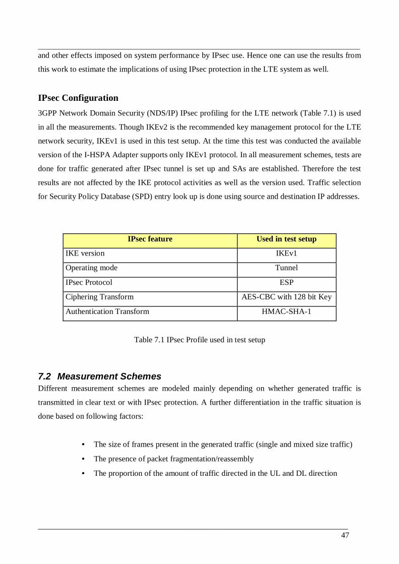
________________________________________________________________________________
_____________________________________________________________________________47
and other effects imposed on system performance by IPsec use. Hence one can use the results from
this work to estimate the implications of using IPsec protection in the LTE system as well.
IPsec Configuration3GPP Network Domain Security (NDS/IP) IPsec profiling for the LTE network (Table 7.1) is used
in all the measurements. Though IKEv2 is the recommended key management protocol for the LTE
network security, IKEv1 is used in this test setup. At the time this test was conducted the available
version of the IHSPA Adapter supports only IKEv1 protocol. In all measurement schemes, tests are
done for traffic generated after IPsec tunnel is set up and SAs are established. Therefore the test
results are not affected by the IKE protocol activities as well as the version used. Traffic selection
for Security Policy Database (SPD) entry look up is done using source and destination IP addresses.
IPsec feature Used in test setup
IKE version IKEv1
Operating mode Tunnel
IPsec Protocol ESP
Ciphering Transform AESCBC with 128 bit Key
Authentication Transform HMACSHA1
Table 7.1 IPsec Profile used in test setup
7.2 Measurement SchemesDifferent measurement schemes are modeled mainly depending on whether generated traffic is
transmitted in clear text or with IPsec protection. A further differentiation in the traffic situation is
done based on following factors:
• The size of frames present in the generated traffic (single and mixed size traffic)
• The presence of packet fragmentation/reassembly
• The proportion of the amount of traffic directed in the UL and DL direction
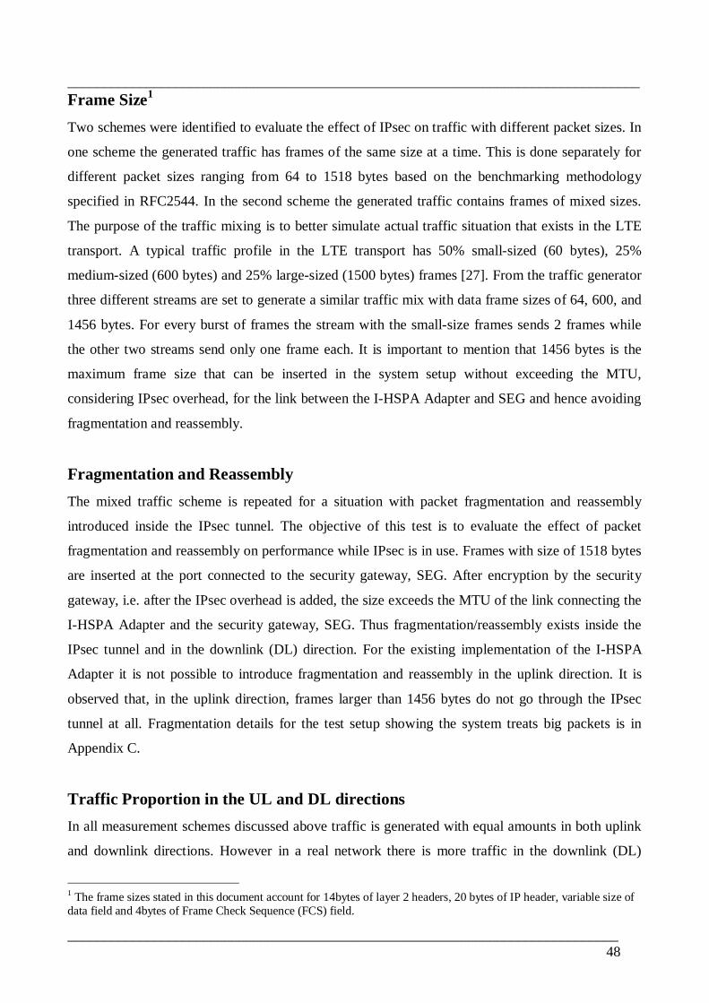
________________________________________________________________________________
_____________________________________________________________________________48
Frame Size1
Two schemes were identified to evaluate the effect of IPsec on traffic with different packet sizes. In
one scheme the generated traffic has frames of the same size at a time. This is done separately for
different packet sizes ranging from 64 to 1518 bytes based on the benchmarking methodology
specified in RFC2544. In the second scheme the generated traffic contains frames of mixed sizes.
The purpose of the traffic mixing is to better simulate actual traffic situation that exists in the LTE
transport. A typical traffic profile in the LTE transport has 50% smallsized (60 bytes), 25%
mediumsized (600 bytes) and 25% largesized (1500 bytes) frames [27]. From the traffic generator
three different streams are set to generate a similar traffic mix with data frame sizes of 64, 600, and
1456 bytes. For every burst of frames the stream with the smallsize frames sends 2 frames while
the other two streams send only one frame each. It is important to mention that 1456 bytes is the
maximum frame size that can be inserted in the system setup without exceeding the MTU,
considering IPsec overhead, for the link between the IHSPA Adapter and SEG and hence avoiding
fragmentation and reassembly.
Fragmentation and ReassemblyThe mixed traffic scheme is repeated for a situation with packet fragmentation and reassembly
introduced inside the IPsec tunnel. The objective of this test is to evaluate the effect of packet
fragmentation and reassembly on performance while IPsec is in use. Frames with size of 1518 bytes
are inserted at the port connected to the security gateway, SEG. After encryption by the security
gateway, i.e. after the IPsec overhead is added, the size exceeds the MTU of the link connecting the
IHSPA Adapter and the security gateway, SEG. Thus fragmentation/reassembly exists inside the
IPsec tunnel and in the downlink (DL) direction. For the existing implementation of the IHSPA
Adapter it is not possible to introduce fragmentation and reassembly in the uplink direction. It is
observed that, in the uplink direction, frames larger than 1456 bytes do not go through the IPsec
tunnel at all. Fragmentation details for the test setup showing the system treats big packets is in
Appendix C.
Traffic Proportion in the UL and DL directionsIn all measurement schemes discussed above traffic is generated with equal amounts in both uplink
and downlink directions. However in a real network there is more traffic in the downlink (DL)
1 The frame sizes stated in this document account for 14bytes of layer 2 headers, 20 bytes of IP header, variable size ofdata field and 4bytes of Frame Check Sequence (FCS) field.
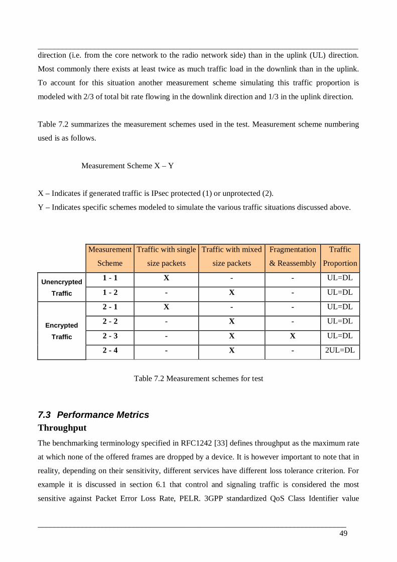
________________________________________________________________________________
_____________________________________________________________________________49
direction (i.e. from the core network to the radio network side) than in the uplink (UL) direction.
Most commonly there exists at least twice as much traffic load in the downlink than in the uplink.
To account for this situation another measurement scheme simulating this traffic proportion is
modeled with 2/3 of total bit rate flowing in the downlink direction and 1/3 in the uplink direction.
Table 7.2 summarizes the measurement schemes used in the test. Measurement scheme numbering
used is as follows.
Measurement Scheme X – Y
X – Indicates if generated traffic is IPsec protected (1) or unprotected (2).
Y – Indicates specific schemes modeled to simulate the various traffic situations discussed above.
Measurement
Scheme
Traffic with single
size packets
Traffic with mixed
size packets
Fragmentation
& Reassembly
Traffic
Proportion
UnencryptedTraffic
1 1 X UL=DL
1 2 X UL=DL
2 1 X UL=DL
EncryptedTraffic
2 2 X UL=DL
2 3 X X UL=DL
2 4 X 2UL=DL
Table 7.2 Measurement schemes for test
7.3 Performance MetricsThroughputThe benchmarking terminology specified in RFC1242 [33] defines throughput as the maximum rate
at which none of the offered frames are dropped by a device. It is however important to note that in
reality, depending on their sensitivity, different services have different loss tolerance criterion. For
example it is discussed in section 6.1 that control and signaling traffic is considered the most
sensitive against Packet Error Loss Rate, PELR. 3GPP standardized QoS Class Identifier value

________________________________________________________________________________
_____________________________________________________________________________50
mapping to performance characteristics for signaling traffic specifies a PELR value of 106. This
means that a single packet loss in a million is acceptable. For this reason throughput measurements
taken for this work are set for 0.0001% loss tolerance corresponding to 106 PERL value.
Throughput is measured in different schemes mainly to evaluate the impacts of the use of IPsec for
different frame sizes.
LatencyBased on RFC2544 [26] latency in the test setup is measured by the traffic generator running a
continuous traffic load in the system for a duration of 120sec. The respective throughput value for
every frame size is used as a traffic load. Approximately 120 tagged frames with timestamps are
used during this period. The recorded latency is the difference between the timestamp when the
frame is received at the receiving port and that recorded when the frame is fully transmitted at the
transmitting port. Two average values are measured for both uplink and downlink direction. The
average of the two measurements is considered for analysis.
Frame Loss RateFrame loss rate is defined in RFC1242 [33] as the percentage of frames that should have been
forwarded by a network device under steady state (constant) load that were not forwarded due to
lack of resources. Frame loss measurement is conducted to study the system behavior under various
traffic load situations. In particular, performance disparities resulting from factors such as frame
sizes, uplinkdownlink traffic proportions and fragmentation are analyzed by using frame loss rate
measurements.

________________________________________________________________________________
_____________________________________________________________________________51
8 Performance AnalysisIn this chapter the findings from various performance measurements are presented and analyzed.
Results from the different measurement schemes, modeled in chapter 7, are compared and observed
discrepancies are explained.
8.1 IPsec and System Performance
8.1.1 Traffic with single size frames (64 to 1400 bytes)ThroughputTo measure the system throughput for different frame sizes, RFC2544 autotest mode is set for the
traffic generator with a 0.0001% loss tolerance, 60 seconds stream duration and a 0.5 Mbps
resolution for the transmitted bit rate. Starting with a given maximum bit rate the traffic generator
goes through a binary search process until a rate with the given loss tolerance is reached. This test is
done for both IPsec encrypted traffic and clear text traffic. The result is plotted as a graph shown in
Figure 8.1. The throughput values stated in the graph account for the total sum of the transmitted bit
rates in both uplink and downlink directions.
Throughput
0.00
10.00
20.00
30.00
40.00
50.00
60.00
64 128 256 512 1024 1280 1400
Frame Size (Bytes)
Thro
uput
(Mbp
s)
IPsecNo IPsec
Figure 8.1 System Throughput for different Frame Sizes

________________________________________________________________________________
_____________________________________________________________________________52
In the test setup the maximum bit rate from the traffic generator is set to be 100 Mbps in each
direction resulting in a total sum of 200 Mbps. However measured throughput is less than 60 Mbps,
about 70% reduction, irrespective of IPsec protection and frame size (Figure 8.1). The reason
behind this fact is that the IHSPA Adapter node is a performance bottle neck for the model setup
with throughput of 30 Mbps and 45 Mbps with and with out IPsec protection, respectively.
It is no surprise that the throughput recorded for IPsec protected traffic is significantly reduced
compared to the clear text traffic (Figure 8.1). IPsec adds an extra overhead and thus reduction in
throughput of about 37%, on average. The reduction in throughput is the expected tradeoff between
providing security and transmitting the traffic unprotected. IPsec overhead is introduced by extra
protocol headers and additional packet processing by the computationally intensive encryption and
authentication algorithms.
An additional observation from the measurement discussed above is that much less throughput is
obtained for small sized frames than for large ones. Particularly, those frames in the order of 60 to
256 bytes are greatly affected by IPsec overhead. One reason behind this decrease is the
significance of headertopayload ratio values for small sized packets. Furthermore, too many
individual IPsec packet processing is done for a given traffic with small packets than with large
packets. In reality there is more number of small packets in a typical traffic profile for mobile data
networks, such as the LTE system [27]. Therefore it is important to consider the effect of such
traffic mix when employing IPsec as a security solution. Frame Loss Rate measurement result
considered for a similar traffic proportion, with 50% small size, 25% medium size and 25% large
size packets, is presented later in this chapter.
LatencyFigure 8.2 depicts average latency measurements from the RFC2544 autotest. To measure latency
of the system model the autotest mode uses the throughput results as traffic load (presented above
in Figure 8.1). For every frame size, traffic amounting to the respective maximum throughput is run
for 120 seconds. Average oneway latency is measured separately for each direction. The average of
these values is considered for analysis.
Irrespective of IPsec protection, it is observed that small packets traverse the system quicker than
big packets. The reason is that more time is needed to process and transmit bigger packets, i.e. more

________________________________________________________________________________
_____________________________________________________________________________53
bits with in a single packet. Neglecting propagation delay, which is the same for the system and
small, the difference in latency is mainly due to the higher processing, serialization and queuing
delays incurred by the bigger packets.
For IPsec protected traffic the worst case latency is observed to be in the order of 0.5 ms. On
average the IPsec overhead introduced an additional packet delay of 0.1 ms. Considering the packet
delay budget (PDB) values for the EPS (shown in Table 8.1.1) for an endtoend latency from UE to
the LTE core, the measured latency values are acceptable. For Packet Delay Budget (PDB) between
a UE and a Policy and Charging Enforcement Function (PCEF), a delay of 20 ms is assumed
between a radio base station and the PCEF [20]. Hence the observed IPsec overhead contribution to
latency over the LTE transport is quite small.
Latency
0.00
0.10
0.20
0.30
0.40
0.50
0.60
64 128 256 512 1024 1280 1400Frame Size (Bytes)
Aver
age
Late
ncy
(ms)
IPsecNo IPsec
Figure 8.2 Average System Latency for different Frame Sizes
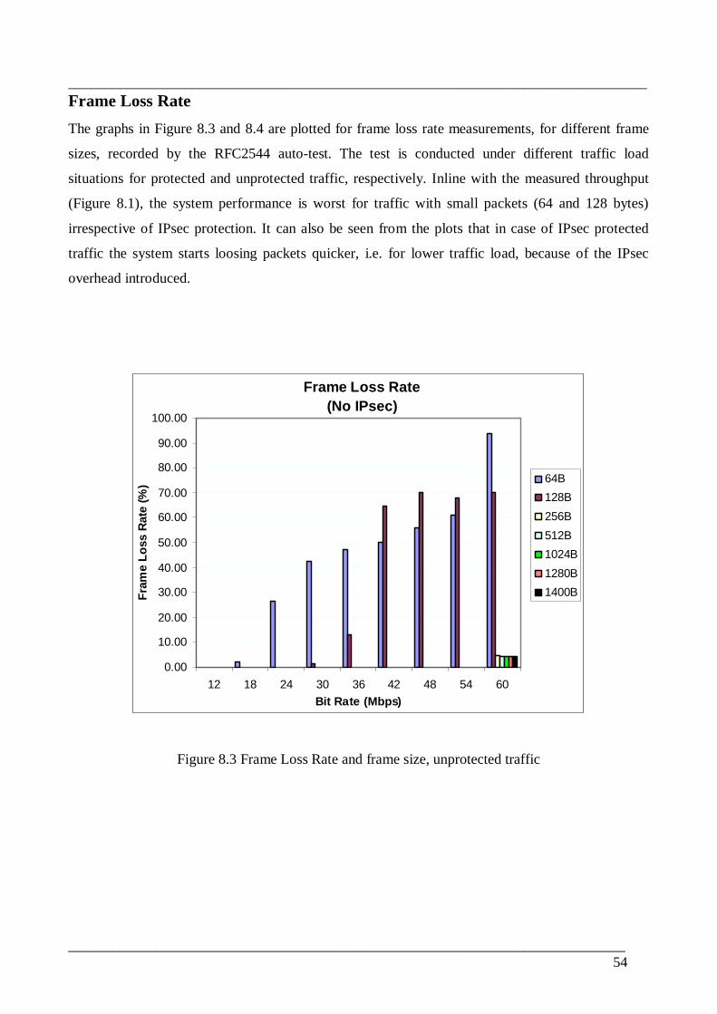
________________________________________________________________________________
_____________________________________________________________________________54
Frame Loss RateThe graphs in Figure 8.3 and 8.4 are plotted for frame loss rate measurements, for different frame
sizes, recorded by the RFC2544 autotest. The test is conducted under different traffic load
situations for protected and unprotected traffic, respectively. Inline with the measured throughput
(Figure 8.1), the system performance is worst for traffic with small packets (64 and 128 bytes)
irrespective of IPsec protection. It can also be seen from the plots that in case of IPsec protected
traffic the system starts loosing packets quicker, i.e. for lower traffic load, because of the IPsec
overhead introduced.
Frame Loss Rate(No IPsec)
0.00
10.00
20.00
30.00
40.00
50.00
60.00
70.00
80.00
90.00
100.00
12 18 24 30 36 42 48 54 60Bit Rate (Mbps)
Fram
e Lo
ss R
ate
(%) 64B
128B256B512B1024B1280B1400B
Figure 8.3 Frame Loss Rate and frame size, unprotected traffic
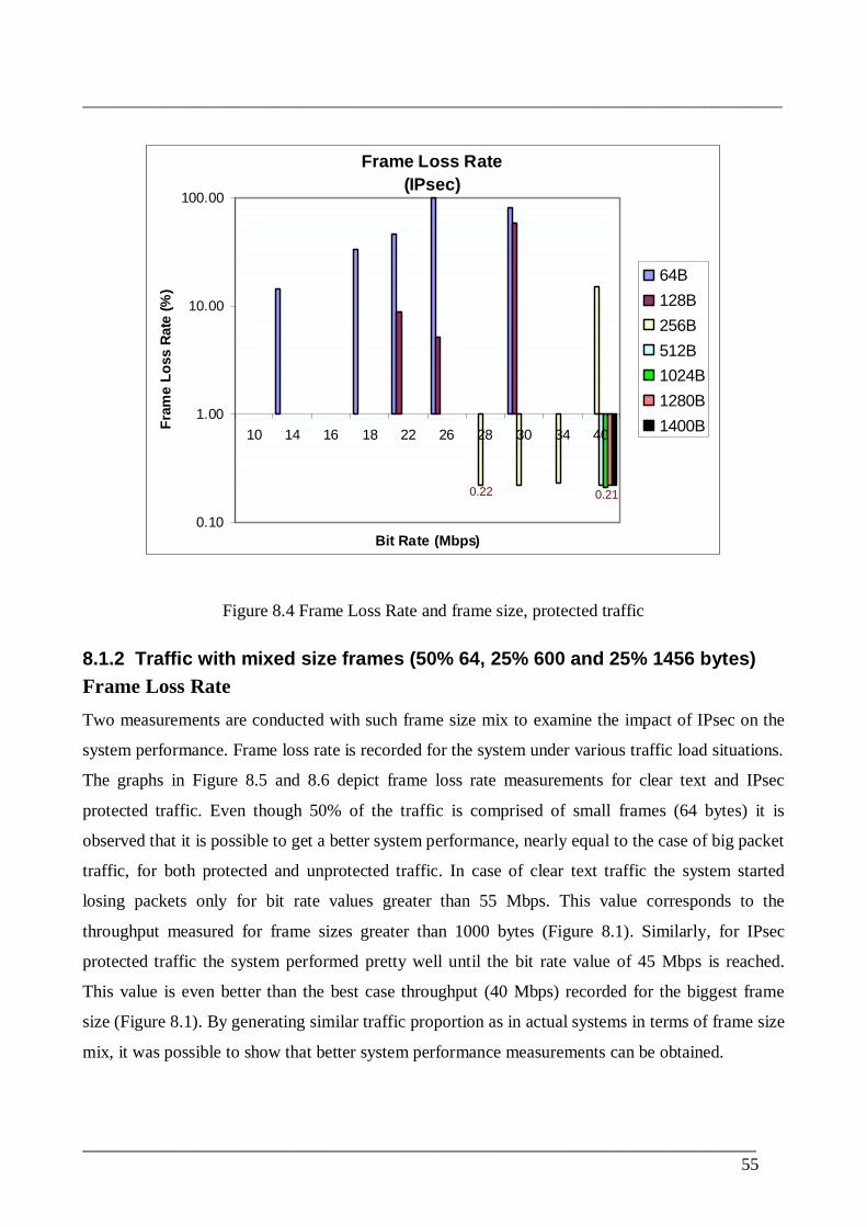
________________________________________________________________________________
_____________________________________________________________________________55
Frame Loss Rate(IPsec)
0.22 0.21
0.10
1.00
10.00
100.00
10 14 16 18 22 26 28 30 34 40
Bit Rate (Mbps)
Fram
e Lo
ss R
ate
(%)
64B128B256B512B1024B1280B1400B
Figure 8.4 Frame Loss Rate and frame size, protected traffic
8.1.2 Traffic with mixed size frames (50% 64, 25% 600 and 25% 1456 bytes)Frame Loss RateTwo measurements are conducted with such frame size mix to examine the impact of IPsec on the
system performance. Frame loss rate is recorded for the system under various traffic load situations.
The graphs in Figure 8.5 and 8.6 depict frame loss rate measurements for clear text and IPsec
protected traffic. Even though 50% of the traffic is comprised of small frames (64 bytes) it is
observed that it is possible to get a better system performance, nearly equal to the case of big packet
traffic, for both protected and unprotected traffic. In case of clear text traffic the system started
losing packets only for bit rate values greater than 55 Mbps. This value corresponds to the
throughput measured for frame sizes greater than 1000 bytes (Figure 8.1). Similarly, for IPsec
protected traffic the system performed pretty well until the bit rate value of 45 Mbps is reached.
This value is even better than the best case throughput (40 Mbps) recorded for the biggest frame
size (Figure 8.1). By generating similar traffic proportion as in actual systems in terms of frame size
mix, it was possible to show that better system performance measurements can be obtained.

________________________________________________________________________________
_____________________________________________________________________________56
Frame Loss RateMixed size traffic, No Fragmentation (DL = UL)
0.00
2.00
4.00
6.00
8.00
10.00
12.00
14.00
16.00
53.9
0
54.7
6
55.1
8
55.6
0
56.0
6
56.5
3
57.4
5
58.4
2
Bit Rate (Mbps)
Fram
e Lo
ss R
ate
(%)
No IPsec
Figure 8.5 Frame Loss Rate for mixed size traffic – No IPsec
Frame Loss RateMixed size traffic, No Fragmentation (DL = UL)
0.00
2.00
4.00
6.00
8.00
10.00
12.00
46.0
8
46.7
1
47.3
3
47.9
8
48.6
5
49.3
4
50.0
4
50.7
7
51.5
2
52.3
0
53.0
9
53.9
1
54.7
5
Bit Rate (Mbps)
Fram
e Lo
ss R
ate
(%)
IPsec
Figure 8.6 Frame Loss Rate for mixed size traffic – IPsec

________________________________________________________________________________
_____________________________________________________________________________57
LatencyTo examine the extra delay IPsec brings on system for traffic with mixed frame sizes, two
measurements are conducted for protected and unprotected traffic. Figure 8.7 and 8.8 show the plots
for the recorded latency values for the system under different load conditions. Similar to the frame
loss rate results, the system performance appeared to be dominated by the big packets. For
unprotected traffic the system latency was constant (∼0.45 ms) for all traffic load values less than
55 Mbps, the maximum bit rate obtained with out frame loss (Figure 8.5). This constant latency
value is comparable to the worst case latency recorded for traffic with big frames, 1400 bytes
(Figure 8.2). The same observation goes for the protected traffic which maintained less than 0.6 ms
delay until traffic load of 45 Mbps is reached, the maximum bit rate without frame loss (Figure 8.6).
The excess delay introduced by IPsec overhead is 0.15 ms with 33.3% increase. In both cases the
delay values show a sudden rise and/or fall after the throughput thresholds are reached (55 Mbps for
unprotected, 45 Mbps for protected). The reason for these results could not be explained. Similar
phenomena were also observed in latency measurements presented in the next two subsections.
LatencyMixed size traffic, No Fragmentation (DL = UL)
0.47
2.84
0.10
1.00
10.00
100.00
53.9
0
54.7
6
55.1
8
55.6
0
56.0
6
56.5
3
57.4
5
58.4
2
Bit Rate (Mbps)
Aver
age
Late
ncy
No IPsec
Figure 8.7 Average Latency for mixed size traffic – No IPsec

________________________________________________________________________________
_____________________________________________________________________________58
LatencyMixed size traffic, No Fragmentation (DL = UL)
2.47
1.56
3.85
0.53
0.10
1.00
10.00
100.00
37.2
4
39.3
3
41.6
9
44.3
3
46.0
8
46.7
1
47.3
3
47.9
8
48.6
5
49.3
4
50.0
4
50.7
7
51.5
2
52.3
0
53.0
9
53.9
1
54.7
5
Bit Rate (Mbps)
Ave
rage
Lat
ency
IPsec
Figure 8.8 Average Latency for mixed size traffic – IPsec
8.2 Packet Fragmentation and System PerformanceBig packets are inserted in the downlink direction to introduce fragmentation and reassembly inside
the IPsec tunnel. It is important to note here that the traffic mix in the uplink direction is as in
previous measurements (50% 64, 25% 600 and 25% 1456 bytes). Thus all this frames go through
the system without the need for fragmentation. However, in the downlink direction, the 1456 bytes
frames are replaced with 1518 bytes frames. When IPsec header is added to these frames the
corresponding IP packet size exceeds MTU size for the link between the two IPsec nodes resulting
in fragmentation and reassembly. Therefore the results obtained in this particular test case are the
effect of only the 12.5% big frames flowing in one direction. Detail on fragmentation is presented in
Appendix C.
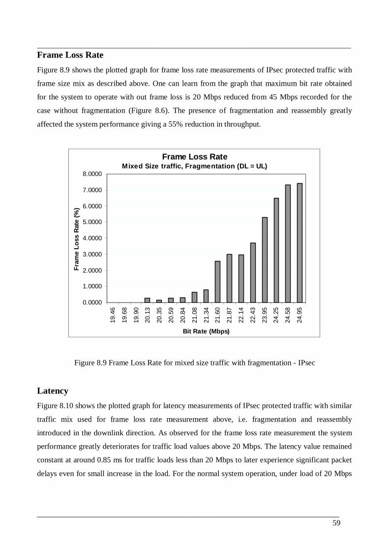
________________________________________________________________________________
_____________________________________________________________________________59
Frame Loss RateFigure 8.9 shows the plotted graph for frame loss rate measurements of IPsec protected traffic with
frame size mix as described above. One can learn from the graph that maximum bit rate obtained
for the system to operate with out frame loss is 20 Mbps reduced from 45 Mbps recorded for the
case without fragmentation (Figure 8.6). The presence of fragmentation and reassembly greatly
affected the system performance giving a 55% reduction in throughput.
Frame Loss RateMixed Size traffic, Fragmentation (DL = UL)
0.0000
1.0000
2.0000
3.0000
4.0000
5.0000
6.0000
7.0000
8.0000
19.4
6
19.6
8
19.9
0
20.1
3
20.3
5
20.5
9
20.8
4
21.0
8
21.3
4
21.6
0
21.8
7
22.1
4
22.4
3
23.9
5
24.2
5
24.5
8
24.9
5
Bit Rate (Mbps)
Fram
e Lo
ss R
ate
(%)
Figure 8.9 Frame Loss Rate for mixed size traffic with fragmentation IPsec
LatencyFigure 8.10 shows the plotted graph for latency measurements of IPsec protected traffic with similar
traffic mix used for frame loss rate measurement above, i.e. fragmentation and reassembly
introduced in the downlink direction. As observed for the frame loss rate measurement the system
performance greatly deteriorates for traffic load values above 20 Mbps. The latency value remained
constant at around 0.85 ms for traffic loads less than 20 Mbps to later experience significant packet
delays even for small increase in the load. For the normal system operation, under load of 20 Mbps

________________________________________________________________________________
_____________________________________________________________________________60
or less, the recorded latency (∼0.85 ms) value has increased by 0.25 ms compared to that recorded
for traffic with out fragmentation (∼0.60 ms, Figure 8.8) giving a 42% extra packet delay.
LatencyMixed Size traffic, Fragmentation (DL = UL)
23.55
18.99
1.46
0.79
0.10
1.00
10.00
100.00
1000.00
19.4
6
19.6
8
19.9
0
20.1
3
20.3
5
20.5
9
20.8
4
21.0
8
21.3
4
21.6
0
21.8
7
22.1
4
22.4
3
23.9
5
24.2
5
24.5
8
24.9
5
Bit Rate (Mbps)
Aver
age
Late
ncy
(ms)
Figure 8.10 Average Latency for mixed size traffic with fragmentation IPsec
8.3 UplinkDownlink Traffic ProportionTo account for actual traffic proportion in the mobile data networks, traffic is generated through the
system setup in such a way that there is twice as much load in the downlink direction than in the
uplink direction. This measurement scheme is modeled in order to examine the possibility of getting
better performance for the downlink direction than observed in previous schemes where the system
is subjected to equal amount of traffic load flowing in both directions.
Frame Loss RateFrame loss rate measurement results for mixed size and IPsec protected traffic with 2/3 of the load
flowing in the downlink direction is plotted as graph (Figure 8.11). As it can be seen from the graph
the system functioned well, without packet loss, until a traffic load of 42 Mbps is reached. This
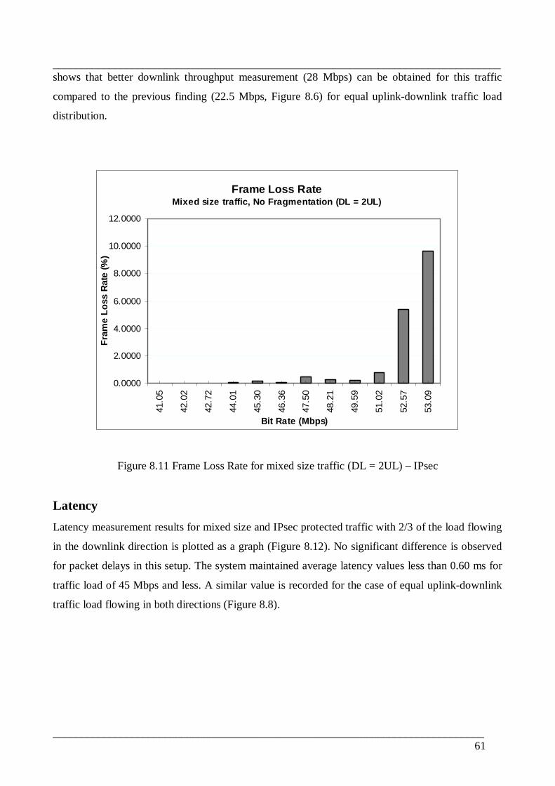
________________________________________________________________________________
_____________________________________________________________________________61
shows that better downlink throughput measurement (28 Mbps) can be obtained for this traffic
compared to the previous finding (22.5 Mbps, Figure 8.6) for equal uplinkdownlink traffic load
distribution.
Frame Loss RateMixed size traffic, No Fragmentation (DL = 2UL)
0.0000
2.0000
4.0000
6.0000
8.0000
10.0000
12.0000
41.0
5
42.0
2
42.7
2
44.0
1
45.3
0
46.3
6
47.5
0
48.2
1
49.5
9
51.0
2
52.5
7
53.0
9Bit Rate (Mbps)
Fram
e Lo
ss R
ate
(%)
Figure 8.11 Frame Loss Rate for mixed size traffic (DL = 2UL) – IPsec
LatencyLatency measurement results for mixed size and IPsec protected traffic with 2/3 of the load flowing
in the downlink direction is plotted as a graph (Figure 8.12). No significant difference is observed
for packet delays in this setup. The system maintained average latency values less than 0.60 ms for
traffic load of 45 Mbps and less. A similar value is recorded for the case of equal uplinkdownlink
traffic load flowing in both directions (Figure 8.8).

________________________________________________________________________________
_____________________________________________________________________________62
LatencyMixed size traffic, No Fragmentation (DL = 2UL)
3.50
0.52
1.62
0.60
0.10
1.00
10.00
100.00
37.5
2
39.2
0
40.1
0
41.0
5
42.0
2
42.7
2
44.0
1
45.3
0
46.3
6
47.5
0
48.2
1
49.5
9
51.0
2
52.5
7
53.0
9
Bit Rate (Mbps)
Aver
age
Late
ncy
(ms)
Figure 8.12 Average Latency for mixed size traffic (DL = 2UL) – IPsec

________________________________________________________________________________
_____________________________________________________________________________63
9 Conclusion and Future WorkInternet security framework, IPsec, is the standardized security solution to be implemented over the
S1 interface of the LTE system. This thesis work analyzed the impacts of IPsec implementation in
the LTE transport based on experimental test results. Performance penalties were studied by
exposing a test system model to different traffic situations.
IHSPA adapter connected to a core security gateway (SEG) is used in the model instead of LTE
eNB. The two nodes have similar IPsec implementations except for slight differences. Therefore the
impacts caused by IPsec application for data protection are considered to be of similar magnitude
for both nodes. Since the main focus of this work is to show the impacts and other effects imposed
on system performance by IPsec use the findings are valid for the LTE eNB as well.
The system behavior analysis with respect to traffic composed of single size packets revealed that
performance significantly deteriorates for small packets (below 256 bytes) with 50 to 60%
reduction in throughput. Latency on the other hand is seen to increase constantly by 0.1 ms for the
whole packet size range used (64 – 1500 bytes). According to this finding it is impossible to use
IPsec to protect traffic which is dominantly characterized by small packets.
By simulating real network traffic mix however, it was possible to show that an acceptable
performance can be gained. Typical traffic profile in mobile broadband networks was simulated
using 50% smallsized, 25 % mediumsized and 25% largesized packets. The performance
measurement results were found to be comparable to the case where traffic is composed of only
large packets indicating acceptable cost for implementing IPsec protection.
Finally, it was also observed that fragmentation and reassembly together with IPsec use affected the
system performance to a great extent. System throughput reduced by more than 50% while latency
increased by 0.25 ms when big packets are introduced into the system. Therefore, it can be
concluded that system design considerations should be made so as to avoid fragmentation and
reassembly after IPsec encryption is applied to protected packets.
________________________________________________________________________________
_____________________________________________________________________________64
Due to equipment and compliant software availability issues as well as time constraints the
following initially intended tasks were not accomplished.
• Testing LTE eNB for actual measurement results (IHSPA Adapter is used instead)
Similar measurement model and schemes can be used to analyze IPsec impacts on the LTE
transport system performance by using actual eNB in the near future.
• Analysis of the implications of IPsec in the migration to IPv6
Related to the migration to IPv6 networks the initial steps to be taken in the LTE system could
be that IPv6 applications from the user and external IP networks will be encapsulated in an IPv4
IPsec over the transport network. In any case the impacts of moving to IPv6 on IPsec
performance and configuration would require thorough analysis in the IPv6 context.
• Verification of the traffic model when LTE is in use.
LTE is not commercially deployed yet and actual traffic situation is not yet known. Therefore
verifying the traffic model when LTE is in use will be worth studying in the future.

________________________________________________________________________________
_____________________________________________________________________________65
References
[1] 3GPP. TS 36.201 V8.3.0, “Technical Specification Group Radio Access Network;
Evolved Universal Terrestrial Radio Access (EUTRA); LTE Physical Layer – General
Description”, March 2009.
[2] 3GPP. TS 36.300 V9.1.0, “Technical Specification Group Radio Access Network;
Evolved Universal Terrestrial Radio Access (EUTRA) and Evolved Universal Terrestrial
Radio Access Network (EUTRAN); Overall description”, September 2009.
[3] 3GPP. TS 25.401 V9.0.0, “Technical Specification Group Radio Access Network;
UTRAN overall description”, December 2009.
[4] 3GPP. TS 36.401 V8.7.0, “Technical Specification Group Radio Access Network;
Evolved Universal Terrestrial Radio Access Network (EUTRAN); Architecture
description”, September 2009.
[5] 3GPP. TS 22.278 V9.5.0, “Technical Specification Group Services and System Aspects;
Service requirements for the Evolved Packet System (EPS)”, December 2009.
[6] 3GPP. TS 33.210 V8.3.0, “Technical Specification Group Services and System Aspects;
3G Security; Network Domain Security; IP network layer security”, June 2009.
[7] 3GPP. TR 33.821 V9.0.0, “Technical Specification Group Services and System Aspects;
Rationale and track of security decisions in Long Term Evolved (LTE) RAN/3GPP
System Architecture Evolution (SAE)”, June 2009.
[8] 3GPP. TS 33.401 V9.1.0, “Technical Specification Group Services and System Aspects;
3GPP System Architecture Evolution (SAE): Security Architecture”, September 2009.
[9] 3GPP. TR 21.902 V8.0.0, “Technical Specification Group Services and System Aspects;
Evolution of 3GPP System”, December 2009.
[10] IETF RFC4301. S. Kent and K. Seo, “Security Architecture for the Internet Protocol”,
December 2005.
[11] IETF RFC4302. S. Kent, “IP Authentication Header (AH)”, December 2005.
[12] IETF RFC4303. S. Kent, “IP Encapsulating Security Payload (ESP)”, December 2005.
[13] IETF RFC4306. C. Kaufman, Ed. “Internet Key Exchange (IKEv2) Protocol”, December
2005.
[14] James S. Tiller, “Technical Guide to IPsec Virtual Private Networks”, 2000.
[15] Naganand Doraswamy, Dan Harkins. “IPsec: The New Security Standard for the Internet,
Intranets, and Virtual Private Networks”, Prentice Hall PTR, 1999.

________________________________________________________________________________
_____________________________________________________________________________66
[16] H. Soussi, M. Hussain*, H. Afifi, D. Seret, “IKEv1 and IKEv2: A Quantitative Analysis”.
June, 2005.
[17] Christos Xenakis, Lazaros Merakos. “IPsecbased endtoend VPN deployment over
UMTS”: Communication Networks Laboratory, Department of Informatics &
Telecommunications, University of Athens.
[18] ITUT Recommendation E.800. “Terms and Definitions Related to Quality of Service and
Network Performance Including Dependability”, 1994.
[19] IETF RFC2475. S. Blake, et al., “An Architecture for Differentiated Services”, December
1998.
[20] 3GPP. TS 23.203 V9.3.0, “Technical Specification Group Services and System Aspects,
Policy and Charging Control Architecture”. December 2009.
[21] IETF RFC2474. K. Nichols, et al., “Differentiated Services Field (DS Field) in IPv4 and
IPv6 Headers”, December 1998.
[22] Lars Völker, Marcus Schöller, Martina Zitterbart, “Introducing QoS mechanisms into the
IPsec packet processing”, IEEE 2007.
[23] IETF RFC3602S. Frankel, R. Glenn, S. Kelly. “The AESCBC Cipher Algorithm and Its
Use with IPsec”, September 2003.
[24] IETF RFC2404. C. Madson, R. Glenn. “The Use of HMACSHA196 within ESP and
AH”, November 1998.
[25] “Long Term Evolution (LTE): A Technical Overview”, Motorola, Inc. 2007.
[26] IETF RFC2544. S. Bradner, J. McQuaid. “Benchmarking Methodology for Network
Interconnect Devices”, March 1999.
[27] Torsten Musiol. “LTE Transport Tutorial”, Nokia Siemens Networks, October 2009.
[28] 3GPP. LTA Paper, UTRAUTRAN Long Term Evolution (LTE) and 3GPP System
Architecture Evolution, 3GPP, http://www.3gpp.org/LTE.
[29] 3GPP. TR 25.913 V9.0.0, “Technical Specification Group Radio Access Network;
Requirements for the Evolved UTRA (EUTRA) and Evolved UTRAN (EUTRAN)”,
December 2009.
[30] 3GPP. TS 23.401 V9.3.0, “Technical Specification Group Services and System Aspects;
General Packet Radio Service (GPRS) enhancements for Evolved Universal Terrestrial
Radio Access Network (EUTRAN)”, December 2009.
[31] 3GPP. TS 23.203 V9.3.0, “Technical Specification Group Services and System Aspects;
Policy and Charging control Architecture”, December 2009.
________________________________________________________________________________
_____________________________________________________________________________67
[32] “Security in the LTESAE Network” http://lteworld.org/whitepaper/securityltesae
network, 17 March 2010.
[33] IETF RFC1242. S. Bradner. “Benchmarking Terminology for Network Interconnection
Devices”, July 1991.
[34] Heiko Niedermayer, Andreas Klenk and George Carle. “The Networking Perspective of
Security Performance – a Measurement Study” Computer Networks and Internet,
University of Tuebingen, Germany.
[35] Gabriela Limon Garcia. “IPsec performance analysis for largescale Radio Access
Networks”, Helsinki University of Technology, July 2008.
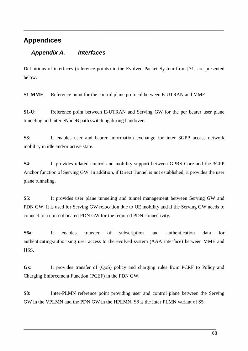
________________________________________________________________________________
_____________________________________________________________________________68
Appendices
Appendix A. Interfaces
Definitions of interfaces (reference points) in the Evolved Packet System from [31] are presented
below.
S1MME: Reference point for the control plane protocol between EUTRAN and MME.
S1U: Reference point between EUTRAN and Serving GW for the per bearer user plane
tunneling and inter eNodeB path switching during handover.
S3: It enables user and bearer information exchange for inter 3GPP access network
mobility in idle and/or active state.
S4: It provides related control and mobility support between GPRS Core and the 3GPP
Anchor function of Serving GW. In addition, if Direct Tunnel is not established, it provides the user
plane tunneling.
S5: It provides user plane tunneling and tunnel management between Serving GW and
PDN GW. It is used for Serving GW relocation due to UE mobility and if the Serving GW needs to
connect to a noncollocated PDN GW for the required PDN connectivity.
S6a: It enables transfer of subscription and authentication data for
authenticating/authorizing user access to the evolved system (AAA interface) between MME and
HSS.
Gx: It provides transfer of (QoS) policy and charging rules from PCRF to Policy and
Charging Enforcement Function (PCEF) in the PDN GW.
S8: InterPLMN reference point providing user and control plane between the Serving
GW in the VPLMN and the PDN GW in the HPLMN. S8 is the inter PLMN variant of S5.

________________________________________________________________________________
_____________________________________________________________________________69
S9: It provides transfer of (QoS) policy and charging control information between the
Home PCRF and the Visited PCRF in order to support local breakout function.
S10: Reference point between MMEs for MME relocation and MME to MME information
transfer.
S11: Reference point between MME and Serving GW.
S12: Reference point between UTRAN and Serving GW for user plane tunneling when
Direct Tunnel is established. It is based on the Iuu/Gnu reference point using the GTPU protocol
as defined between SGSN and UTRAN or respectively between SGSN and GGSN. Usage of S12 is
an operator configuration option.
S13: It enables UE identity check procedure between MME and EIR.
SGi: It is the reference point between the PDN GW and the packet data network. Packet
data network may be an operator external public or private packet data network or an intra operator
packet data network, e.g. for provision of IMS services. This reference point corresponds to Gi for
3GPP accesses.
Rx: The Rx reference point resides between the AF and the PCRF.

________________________________________________________________________________
_____________________________________________________________________________70
Appendix B. Test Setup Equipments
Traffic GeneratorAnritsu MD1230BVersion 5.0Data Quality AnalyzerWindows XP NTFS file system1000BaseSX/LX/LH/ZX and 10/100/1000BaseThttp://www.anritsu.co.jp
Security Gateway, SEGCisco Wireless Security Gateway (WSG)Version 1.2Built on Cisco Service and Application Module for IP (SAMI)SAMI mountable on Cisco 7600 serious RouterIKEv1 and IKEv2X.509 Certificate and PreShared key authentication and CRL
IHSPA AdapterNSN IHSPA Adapter IPsec integratedRelease 2.0Additional unit to NodeB which upgrades traditional 3G NodeB to IHSPA NodeBIPsec for Control and Management plane traffic (IHSPA NodeBßà IHSPA Core)IKEv1X.509 Certificate and PreShared key authentication

________________________________________________________________________________
_____________________________________________________________________________71
Appendix C. Packet Fragmentation
The following figure illustrates the packet fragmentation scenarios in the test network.