Embed Size (px)
Citation preview

Impedance control for fusing multisensorial systems in robotic manipulation tasks
J. POMARES, G. J. GARCIA, F. TORRES
Physics, Systems Engineering and Signal Theory Department University of Alicante
PO Box 99, 03080, Alicante SPAIN
Abstract: - In this paper an impedance control scheme is described in order to allow the joint use of visual and force information for controlling a robot during the tracking of a surface. A visual servoing system is employed for following a trajectory in the image space. The impedance control modifies the trajectory obtained from the visual servoing system allowing the system to maintain a constant force with respect the surface. In order to improve the system behaviour an adaptive approach is proposed so that the tracking velocity is modified depending on the value of the Generalized Likelihoot Ratio obtained from the interaction forces measured during the tracking. Key-Words: - Impedance control, Force control, Image based control, visual servoing, adaptive control, Sensor fusion 1 Introduction In order to fuse the visual and force information, the fact that the two sensors measure different physical phenomena of different natures must be taken into consideration. The visual information can be employed for controlling the robot position and the force information for controlling the interaction. This paper describes in detail an impedance control based method for fusing visual and force information allowing the joint use of both sensors to control the task. So far, most of the applications developed for combining visual and force information employ hybrid control [1][5]. In such a case, the workspace must be precisely known, so that a division of the directions controlled by force and those controlled by position (i.e., using a visual servoing system) is first carried out. With a view to increase the versatility of the system and improving its response to the uncertainties that arise during the tracking of a surface, a special visual impedance control system is proposed, which uses the information obtained from a visual servoing system which tracks a previous generated trajectory. These approaches for fusing visual and force information do not consider the possibility of both sensors providing contradictory information during the task. Thus, in unstructured environments it can happen that the visual servoing system establishes a movement direction that is impossible according to the interaction information obtained from the force sensor. In this paper, we consider this possibility and the sensorial information
obtained is processed to allow the use of both sensors for controlling the robot. Once the information is processed, the concept of visual impedance [4] is used together with our previous experiences in fusing multisensorial systems [7] to define a new impedance control based multisensorial method. The system proposed in this article is applied to the tracking of a surface that implies a combined force-position control. To increase the robustness, a Kalman Filter is applied and from this filter is also obtained the Generalized Likelihoot Ratio (denoted here as GLR) [9]. From this parameter is generated an adaptive approach which increases or decreases the tracking speed depending on the quality criteria obtained from the GLR. This paper is organized as follows: Section 2 describes the main characteristics of the tracked trajectory and the notation used. In Section 3, the impedance control system is described. Secton 4 shows the visual servoing system defined for tracking trajectories in the image space. In Section 5 the formulation of the adaptive approach for fusing the force information with that from the visual servoing system is described. In Section 6, experimental results, using an eye-in-hand camera system, confirm the validity of the control scheme proposed. The final section presents the main conclusions arrived at. 2 Notation In this paper, we suppose that the robot must track a surface following a desired trajectory in the 3D space,
2005 WSEAS Int. Conf. on DYNAMICAL SYSTEMS and CONTROL, Venice, Italy, November 2-4, 2005 (pp357-362)
γ(t). The robot has a camera at the end-effector and by sampling γ(t) (with period T), a sequence of N discrete values is obtained, each of which represents N intermediate positions of the camera k k 1...N∈γ/ . From this sequence, the discrete trajectory of the object in the image { }kS k 1...N= ∈s/ can be
obtained, where ks is the set of M points or features observed by the camera at instant k,
{ }k ki i 1...M= ∈s /f (the robot is able to track these
features during the tracking). In this paper we are not interested in image processing issues, therefore, the tracked target is composed of four grey marks whose centres of gravity will be the extracted features. The commanded velocity for the visual servoing and for the force control systems are C
Vv and CFv
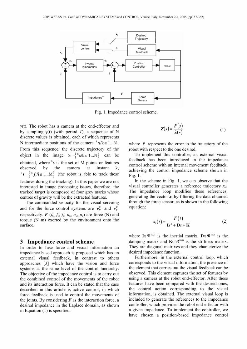
respectively. F (fx, fy, fz, nx, ny, nz) are force (N) and torque (N m) exerted by the environment onto the surface. 3 Impedance control scheme In order to fuse force and visual information an impedance based approach is proposed which has an external visual feedback, in contrast to others approaches [3] which have the vision and force systems at the same level of the control hierarchy. The objective of the impedance control is to carry out the combined control of the movements of the robot and its interaction force. It can be stated that the case described in this article is active control, in which force feedback is used to control the movements of the joints. By considering F as the interaction force, a desired impedance in the Laplace domain, as shown in Equation (1) is specified.
( ) ( )( )sss
xFZ ~= (1)
where x represents the error in the trajectory of the robot with respect to the one desired. To implement this controller, an external visual feedback has been introduced in the impedance control scheme with an internal movement feedback, achieving the control impedance scheme shown in Fig. 1. In the scheme in Fig. 1, we can observe that the visual controller generates a reference trajectory xd. The impedance loop modifies these references, generating the vector xi by filtering the data obtained through the force sensor, as is shown in the following equation:
( ) ( )i 2
tt
s s=
+ +I D KF
x (2)
where I∈ℜnxn is the inertial matrix, D∈ℜnxn is the damping matrix and K∈ℜnxn is the stiffness matrix. They are diagonal matrixes and they characterize the desired impedance function. Furthermore, in the external control loop, which corresponds to the visual information, the presence of the element that carries out the visual feedback can be observed. This element captures the set of features by using a camera at the robot end-effector. After these features have been compared with the desired ones, the control action corresponding to the visual information, is obtained. The external visual loop is included to generate the references to the impedance controller, which provides the robot end-effector with a given impedance. To implement the controller, we have chosen a position-based impedance control
Inverse Kinematics
Position Controller
Visual feedback
Force Sensor
F
xi
xd
Visual control s
xo qo
q
Impedance-1
sd Desired Trajectory
Robot
Fig. 1. Impedance control scheme.
2005 WSEAS Int. Conf. on DYNAMICAL SYSTEMS and CONTROL, Venice, Italy, November 2-4, 2005 (pp357-362)

system called accommodation control [8] in which the desired impedance is limited to pure damping D (In [4] the main aspects of the stability of this type of control are shown):
( )C C -1V d= − ⋅ −Dv v F F (3)
where Cv is the velocity to be applied to the robot with respect to the camera coordinate frame and the term C
Vv is obtained by using the visual servo controller described in next section. 4 Visual servo control Each sample, ks, is generated from each position k γ as is described in Section 2. These positions are obtained considering that the time between two consecutive samples is constant, so that
k+1 k+1 kt t t T∆ = − = where T is the video rate. The desired trajectory to be tracked in the image is obtained using a natural cubic B-spline (the spline interpolation problem is stated as: given image points
{ }kS k 1...N= ∈s/ and a set of parameter values
{ }k k 1...NtΓ = ∈/ we want a cubic B-spline curve s(t)
such that s(kt)=ks): ( ) k 3 k 2 k k
d t t t t += + +s A B C D (4)
where k k k k, , ,A B C D are obtained from the samples in the image space at the given instants. To perform the tracking of the desired trajectory in the image space, an image-based control scheme to regulate to 0 the following vision-based task function is used [3]:
( )( )+
f dˆ - t= ⋅J s se (5)
where s are the extracted features from the image and
+fJ is an estimation of the pseudoinverse of the
interaction matrix. To carry out the tracking of the trajectory, the following velocity must be applied to the robot (with respect to the coordinate frame located at the eye-in-hand camera):
( )dC +
V V fλ +t
t∂
= − ⋅ ⋅∂
sJv e (6)
where λV > 0 is the gain of the proportional controller. Therefore this is the term C
Vv in Equation (3). Up to now, the approaches for fusing visual and
force information do not consider the possibility of both sensors providing contradictory information at a given moment of the task (the visual servoing system establishes a movement direction that is impossible according to the interaction information obtained from the force sensor). To assure that a given task in which it is required an interaction with the setting is correctly developed, the system must carry out a variation of the trajectory in the image, depending on the spatial restrictions imposed by the interaction forces. Therefore, given a collision with the setting and having recognized the normal vector of the contact surface [7], the transformation Tr that the camera must undergo to fulfil the spatial restrictions, is determined. This transformation is calculated so that it represents the nearest direction to the one obtained from the image-based control system, and which is contained in the plane of the surface. Thus, we guarantee that the visual information will be coherent with the information obtained from the force sensor. To do so, considering f to be the position of a given feature extracted by the camera at a given instant, and [Ri ti] (rotation and translation) a sampling of the transformation Tr that the camera undergoes during the tracking of the recognized surface, the feature '
if extracted in each one of these positions will be:
' -1
i i i / z= ⋅ ⋅ ⋅ + ⋅A R A A tf f (7)
where z is the distance between the camera and the object from which the features are extracted and A is the following intrinsic parameter matrix:
( )( )
u u 0
v 0
f f cot θ0 f / sin θ0 0 1
p p up v
⋅ − ⋅ ⋅ = ⋅
A (8)
Considering the homogeneous image coordinates of a feature fi=[ui, vi, 1], u0 and v0 are the pixel coordinates of the principal point, f is the focal length, pu and pv are the magnifications in the u and v directions respectively, and θ is the angle between these axes. From the sampling of the desired trajectory in the image, '
if , a spline interpolator is applied to obtain the desired trajectory in the image. 5 Adaptive tracking of surfaces An adaptive tracking is developed so that the velocity of the visual servoing system is increased if the tracking is correctly developed, and decreased if errors appears during the tracking and the system cannot maintain constant contact with the surface. To
2005 WSEAS Int. Conf. on DYNAMICAL SYSTEMS and CONTROL, Venice, Italy, November 2-4, 2005 (pp357-362)

do so we have developed a system for detecting changes in the model considered by a Kalman filter applied to the interaction forces obtained. To do so we have determined the Generalized Likelihoot Ratio (GLR) (the setup of the different parameters of the GLR can be seen in our previous works [7]). The task to be developed consists of using visual and force information for maintaining a constant contact during the tracking of a surface. In this case when the value of GLR increases, this can be obtained when, for several possible reasons (irregularities in the surface, errors in the trajectory generated by the visual servoing system, high velocity, etc.) the tracking is not correctly done and, therefore, the system cannot maintain a constant force on the surface. The behaviour is then more oscillatory, and changes are generated in the interaction forces, increasing the value of GLR. To correct this behaviour, the velocity obtained from the visual servoing system is decreased when the value of GLR increases. Empirically we have concluded that when GLR is lower than 500 (GLR1), the system behaves correctly. Furthermore, if a change in the surface occurs, the value of GLR will be greater than 1000 (GLR2). Between both values of GLR is obtained a range of values of GLR that can be obtained when a change in the surface begins or when the system works incorrectly. In this case, a weight is applied to the control action corresponding to the visual servoing system with the aim of correcting defects in the tracking. When GLR is equal to GLR1, or lower, the velocity established by the computer vision system is indicated in Equation (6). However, when GLR is equal to GLR2, we define C
Vminv as the minimum velocity, empirically obtained, to carry out the tracking of the trajectory and which allows the system to correct the possible defects in this trajectory (the effect of the force control in the trajectory is increased in the global control action). Therefore, considering a decreasing evolution of the weight function applied to the velocity obtained from the visual servoing system, this function will have the following value in the range GLR1 ≤ GLR < GLR2:
V2 1
12 1
1 GLRGLR GLR
11 GLRGLR GLR
pp
p
−= ⋅ +
−−
+ − ⋅−
(9)
where CVmin
CV
p =vv
and the final control action applied
by the visual servoing system in this range will be equal to C
V Vp ⋅ v
6 Results In this section we describe the results obtained from the application of the proposed system to the tracking of a given surface which requires the joint use of the information obtained from the force sensor (control of the robot’s interaction with its workspace) together with that obtained from the computer vision system. To demonstrate the results, we first describe the experimental setup. Subsequently the results obtained from tracking different surfaces applying the adaptive approach described in Section 5 are shown. Finally, the correction of the orientation by using the adaptive control approach is also shown. 6.1 Experimental setup In Fig. 2, the robotic system employed is shown.
Fig 2. Experimental setup.
The characteristics of each of the devices are: • “Eye-in-hand” system: The capturing of images
from the robot end-effector is carried out with a JAI-M536 mini-camera with a remote optical head. MATROX GENESIS is used as image acquisition and processing board. The camera is able to acquire up to 30 frames/second and is previously submitted to a calibration process (focal length is 7,5 mm),
• Manipulation system: This is composed of a 7 d.o.f. Mitsubishi PA-10 robot equipped with a force sensor (67M25A-I40 from JR3. Inc.). The robot has a gripper at the end-effector.
6.2 Tracking surfaces As is described in Section 5, the GLR presents greater values when the robot is not able to maintain the constant contact with the surface. To avoid this situation an adaptive approach is described so that the tracking velocity is modified depending on the GLR. Fig. 3 and Fig. 4 show two experiments for
camera Force sensor
Tracked surface
Gripper
2005 WSEAS Int. Conf. on DYNAMICAL SYSTEMS and CONTROL, Venice, Italy, November 2-4, 2005 (pp357-362)

tracking a plane surface. The first graph of each figure represents the applied force in z direction fusing visual and force information and without applying any weight to the visual servoing system. In the second graph the proposed adaptive strategy is used (see Section 5). We can observe that using the adaptive strategy the system response is less oscillating. Using this strategy the system allows to maintain the constant contact force with the surface.
- 12
- 10
- 8
- 6
- 4
- 2
0
1 3 5 7 9 11 13 15 17 19 2 1 2 3 2 5 2 7 2 9 3 1 3 3 3 5 3 7 3 9 4 1 4 3 4 5 4 7 4 9 5 1 5 3 5 5 5 7 5 9 6 1 6 3 6 5 6 7
-12
-10
-8
-6
-4
-2
01 3 5 7 9 11 13 15 17 19 21 23 25 27 29 31 33 35 37 39 41 43 45 47 49 51 53 55 57 59 61 63 65 67
Fig. 3. Comparison between the obtained forces without using and using the adaptive approach.
Experiment 1.
-12
-10
-8
-6
-4
-2
01 3 5 7 9 11 13 15 17 19 21 23 25 27 29 31 33 35 37 39 41 43 45 47 49 51 53 55 57 59 61 63 65 67 69 71 73 75
-12
-10
-8
-6
-4
-2
0
1 4 7 10 13 16 19 22 25 28 31 34 37 40 43 46 49 52 55 58 61 64 67 70 73 76
Figure 4. Comparison between the obtained forces without using and using the adaptive approach.
Experiment 2 During the tracking of the surface the robot must not only maintain the constant force with the surface, but also to correct possible errors in the orientation of the robot with respect the surface (in Fig. 5 the desired orientation of the robot with respect the surface is represented). The next experiment shows the results obtained when the robot begins the tracking with an incorrect orientation with respect the surface. In this case, the impedance control scheme modifies the orientation during the tracking so that the torques are compensated during the motions established by the visual servoing system.
Fig 5. Desired orientation of the robot with respect the
surface.
Fig 6. Gripper coordinate frame. To carry out the task it is considered that the interaction forces are obtained with respect the coordinate system G represented in Fig. 6. In a situation in which the gripper is not correctly orientated with respect the surface the torques in directions yG, zG must be compensated, maintaining a constant force in direction xG. In this case, in order to correct the orientation, the desired force Fd in Equation (3) is [-5, 0, 0, 0, 0, 0]T. During this experiment the evolution of the torques in directions y,z is shown in Fig. 7. In this experiment the robot continues the tracking of the surface by using the visual servoing system. Furthermore during the tracking the gripper maintains the contact with the surface. In order to illustrate the evolution of the gripper orientation during the experiment in Figure 8 different orientations obtained during the tracking are represented. We can see that finally the robot is correctly orientated with respect the surface.
Fz (N)
Iterations (with the adaptive approach)
Fz (N) Iterations
Iterations
Fz (N)
Fz (N) Iterations (with the adaptive approach)
G
xG
yG
zG
2005 WSEAS Int. Conf. on DYNAMICAL SYSTEMS and CONTROL, Venice, Italy, November 2-4, 2005 (pp357-362)

0
0,2
0,4
0,6
0,8
1
1,2
1 30 59 88 117 146 175 204 233 262 291 320 349 378 407 436 465 494 523 552 581
nz ny
Fig 7. Evolution of the torques in directions z, y
during the tracking.
Fig 8. 3-D trajectory of the gripper during the orientation.
7 Conclusions In this paper a new method for fusing sensorial information from a computer vision system with that from a force sensor has been described. The method was applied to a task which consists of following a surface with the gripper. In this application, it is not only necessary to obtain given features in the image from the initial ones, but a tracking of the desired trajectory between them, fulfilling the desired spatial restrictions, is also necessary for the correct tracking to be carried out. The impedance control scheme allows the adaptive combination of the force control with the visual servoing system. To do so the GLR is obtained so that the value of this parameter is employed to verify if the tracking is correctly developed. The results obtained show that the adaptive approach improves the system behaviour obtaining a less oscillating evolution and maintaining a given constant force with respect the surface.
References: [1] Baeten, J. and Schutter, J. De.: Hybrid
Vision/Force Control at Corners in Planar Robotic-Contour Following. IEEE/ASME Transactions on Mechatronics, Vol.7, No 2, 2002, pp. 143 - 151.
[2] Hutchinson, S., Hager, G. D. and Corke, P. I.: A tutorial on visual servo control, IEEE Transactions on Robotics and Automation, Vol. 12, No. 5, 1996, pp. 651-670.
[3] Mezouar, Y., Chaumette, F. Path Planning For Robust Image-based Control. IEEE Transactions on Robotics and Automation, Vol. 18, No. 4, 2002, pp. 534-549.
[4] Morel, G., Malis, E. Boudet, S. Impedance based combination of visual and force control, Proc IEEE International Conference on Robotics and Automation, Leuven, Belgium. 1998. pp. 1743-1748.
[5] Nelson, B. J. and Khosla, P. K.: Force and vision resolvability for assimilating disparate sensory feedback, IEEE Transaction on Robotics and Automation, Vol. 12, No. 5, 1996, pp. 714-731.
[6] Nelson, B. J., Morrow, J. and Khosla, P. K.: Robotic manipulation using high bandwith force and vision feedback. Mathl. Computer Modelling, Vol. 24, No. 5/6, 1996, pp. 11-29.
[7] Pomares, J., Torres, F.. Movement-flow based visual servoing and force control fusion for manipulation tasks in unstructured environments. IEEE Transactions on Systems, Man, and Cybernetics—Part C, Vol. 35, No. 1, 2005, Pp. 4 – 15.
[8] Whitney, D. E.: Force feedback control of manipulator fine motions. Journal of Dynamic Systems, Measurement and Control, 1977, pp. 97-97.
[9] Willsky, A. S., Jones, H. L. A generalized likelihood ration approach to the detection and estimation of jumps in linear systems. IEEE Trans. Automat. Contr., Vol. 21. No. 1. 1976. pp. 108-112.
Torques Nm.
Iterations
2005 WSEAS Int. Conf. on DYNAMICAL SYSTEMS and CONTROL, Venice, Italy, November 2-4, 2005 (pp357-362)