Embed Size (px)
Citation preview
Impeller Design for Liquid-Liquid Dispersion Using VisiMix
RSD/Turbulent
Matthew Jörgensen
860-460-9611
Jerry Salan
Available for public release
Outline
• Modeling a liquid-liquid system in VisiMix
– How we used PVM to calculate drop size
• PVM drop size matched to VisiMix to “calibrate” the model
• RSD to model disperserator
• Mapped VisimixRSD properties to VisiMixTurbulent to model drop size
• Used VisiMix to evaluate multiple impeller configurations
2
What do we do?
• Transition chemical processes to the plant environment– Identify engineering challenges
including heat transfer, mass transfer, and mixing
– Evaluate chemistry in the laboratory using in situ tools (IR, Raman, FBRM, PVM, heat flow)
• Evaluate pilot and production equipment. Validate processes through scale-down experiments
• Develop low-cost chemical processes
3

Background• Design an automated laboratory reactor to replace the
current lab system for the evaluation of raw materials in
the production of Propylene Glycol Dinitrate (PGDN).
• Maintain same degree of mixing as traditional system
4
• PGDN is the main ingredient in Otto II fuel used in torpedoes.
• It is manufactured in a continuous process
• The nitration is highly exothermic and requires intimate mixing to avoid ‘hot spots’
• Poorly mixed systems can result in ‘fume offs’
5
Background

Reaction
6
OH OH
O
O N+
O-
O
N+
O-
O
Mixed Acid
• Propylene Glycol is added to mixed acid (nitric and sulfuric)• Resulting liquid PGDN is the light phase suspended in the heavy phase
mixed acid
• In the past, propylene glycol shipmentshave been contaminated with small amounts
of impurity resulting in poor separation in production equipment
• Lab-scale nitration was designed to mimicsame degree of mixing as production
nitrator
• Each shipment must meet a specification, Including separation time, before being
used in the plant.
Laboratory Reactor Constraints
• The main point of the automation is to increase
worker safety, while maintaining same degree of
mixing
– Allow for comparison back to historical data
– Droplet size may impact separation times
– Identify problematic lots of propylene glycol
• Match the mixing that they have in the current
setup
– VisiMix to model both existing and proposed lab reactor
7
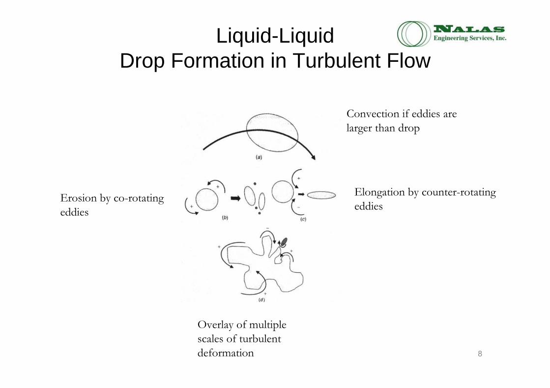
Liquid-Liquid Drop Formation in Turbulent Flow
Convection if eddies are
larger than drop
Erosion by co-rotating
eddies
Elongation by counter-rotating
eddies
Overlay of multiple
scales of turbulent
deformation 8

Liquid-Liquid Drop Formation in Turbulent Flow
In a low viscosity dispersed phase, the classical relationship between mean diameter and impeller Weber number:
d32 = Sauter mean drop diameterD = impeller diameter
σ = Interfacial tensionρ = DensityN = impeller speed
γ = shear rate
with
9It is possible to match drop diameter and level of dispersion between two geometrically similar
systems that use the same dispersed phases by matching the shear in the two systems.
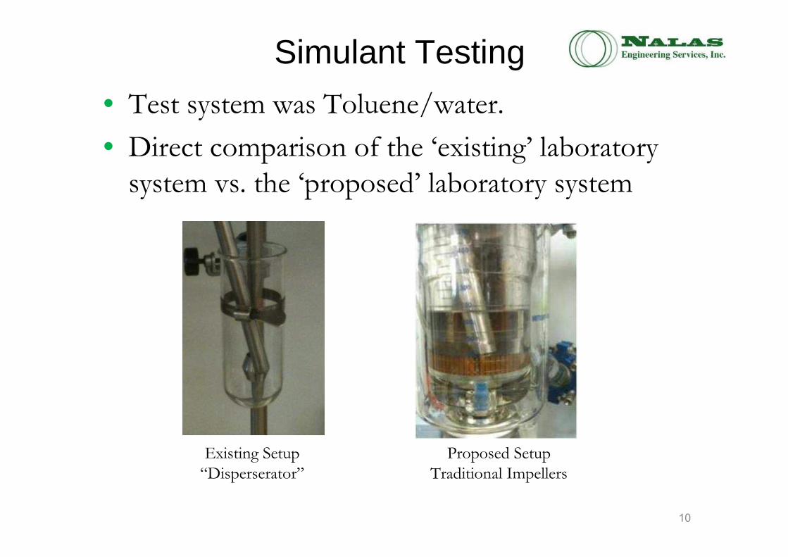
Simulant Testing
• Test system was Toluene/water.
• Direct comparison of the ‘existing’ laboratory system vs. the ‘proposed’ laboratory system
10
Existing Setup
“Disperserator”
Proposed Setup
Traditional Impellers

VisiMix Inputs for Liquid-Liquid Mixing
• Interfacial Surface tension between the two phases
• Density of both phases
• Index of admixtures
– This is a measure of the system to stabilize drops
• Electrolytes
• Surfactants
• Etc.
11
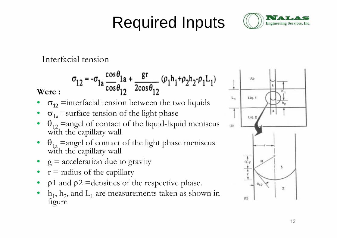
Required Inputs
Were :
• σ12 =interfacial tension between the two liquids
• σ1a =surface tension of the light phase• θ12 =angel of contact of the liquid-liquid meniscus
with the capillary wall
• θ1a =angel of contact of the light phase meniscus with the capillary wall
• g = acceleration due to gravity
• r = radius of the capillary
• ρ1 and ρ2 =densities of the respective phase. • h1, h2, and L1 are measurements taken as shown in
figure
Interfacial tension
12
Required Inputs
• Densities of the two phases were measured after the phases had been mixed and allowed to separate.• This is to account for the change in density due to the solubility of the two materials with each other.
13
Required Inputs
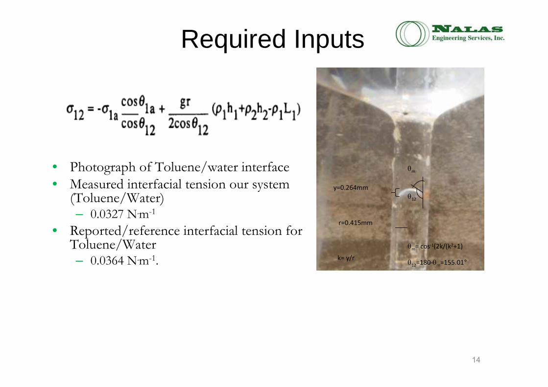
• Photograph of Toluene/water interface
• Measured interfacial tension our system (Toluene/Water)– 0.0327 N.m-1
• Reported/reference interfacial tension for Toluene/Water– 0.0364 N.m-1.
y=0.264mm
r=0.415mm
k= y/r
θ12
θm= cos-1(2k/(k2+1)
θ12=180-θm=155.01°
θm
14

Particle Vision Microscopy: PVMIn situ probe that allows for:
•Detect multiple phases: Gas, Bubbles, Droplets, Oil
•Characterize Particle Shape
•Polymorphic crystallization characterization
•Visualize morphology changes
•Understand dynamics of polymorph transitions
•Characterize surface roughness
•Understand particle dynamics and interactions: growth,
nucleation, agglomeration, and breakage phenomena
•Determine root cause of particle processing problems
15
Validate Model Using PVM
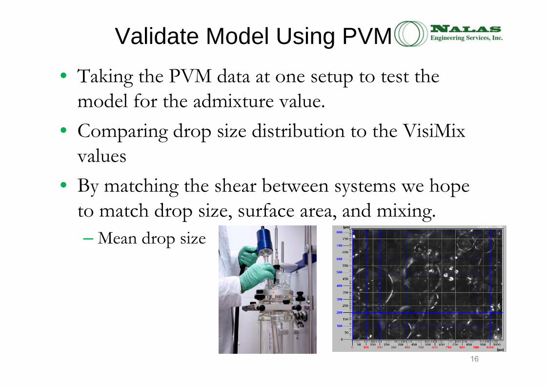
• Taking the PVM data at one setup to test the model for the admixture value.
• Comparing drop size distribution to the VisiMix values
• By matching the shear between systems we hope to match drop size, surface area, and mixing.
– Mean drop size
16

Calculating Drop Diameter from PVM
17
Average of drop diameters from
PVM image
Repeat with another image
The average diameter for all three images is then averaged again and that value is the
drop diameter for that RPM
Repeat a third time…
RC-1 Experiments
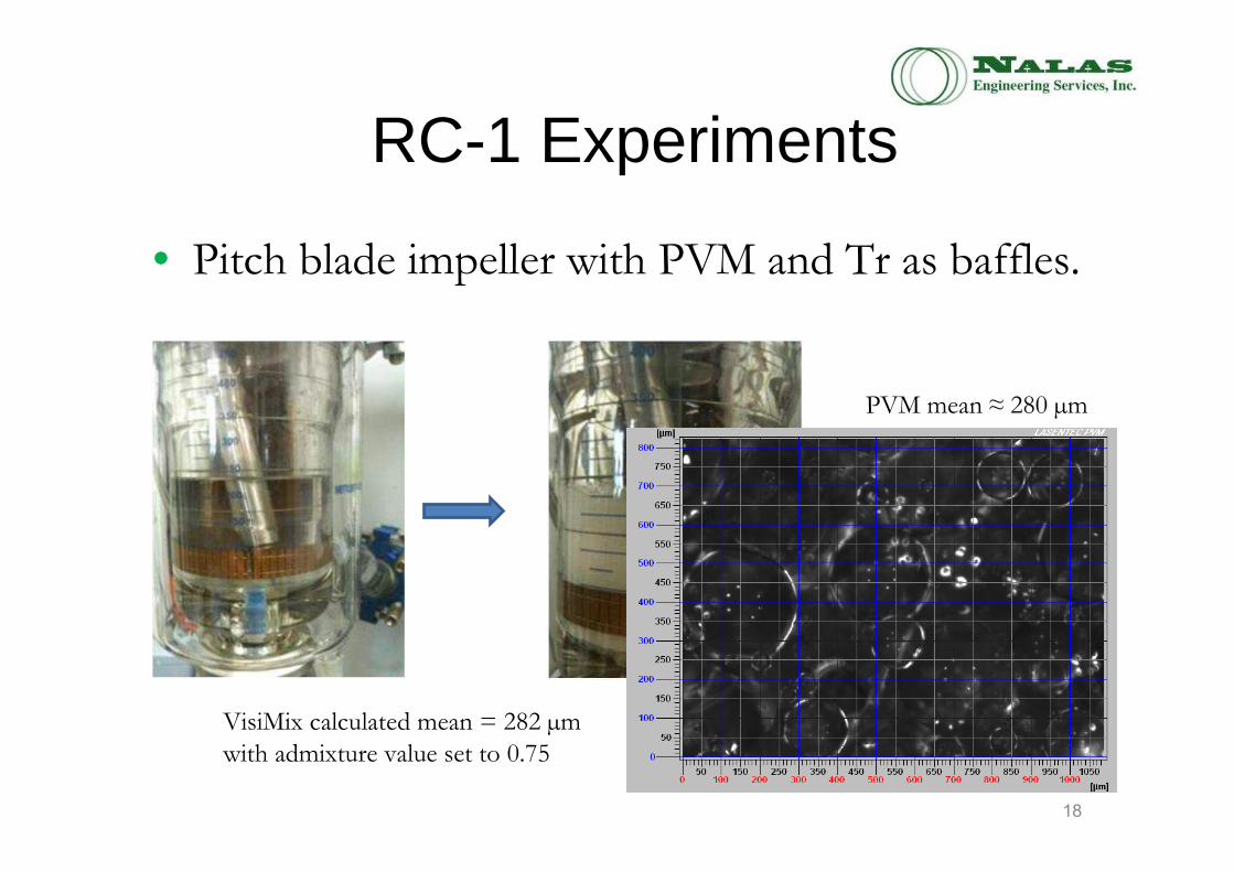
• Pitch blade impeller with PVM and Tr as baffles.
PVM mean ≈ 280 µm
VisiMix calculated mean = 282 µm
with admixture value set to 0.75
18
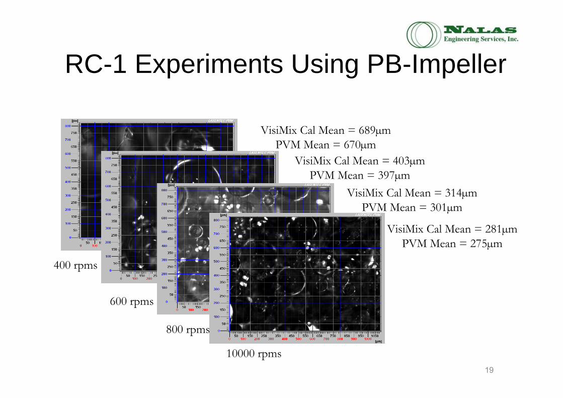
RC-1 Experiments Using PB-Impeller
VisiMix Cal Mean = 689µm
PVM Mean = 670µm
VisiMix Cal Mean = 403µm
PVM Mean = 397µm
VisiMix Cal Mean = 314µm
PVM Mean = 301µm
VisiMix Cal Mean = 281µm
PVM Mean = 275µm
400 rpms
600 rpms
800 rpms
10000 rpms
19
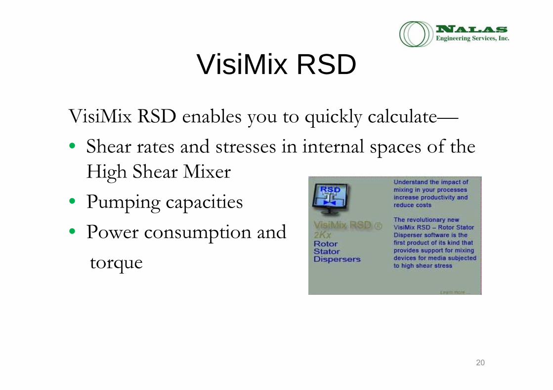
VisiMix RSD
VisiMix RSD enables you to quickly calculate—
• Shear rates and stresses in internal spaces of the High Shear Mixer
• Pumping capacities
• Power consumption and
torque
20
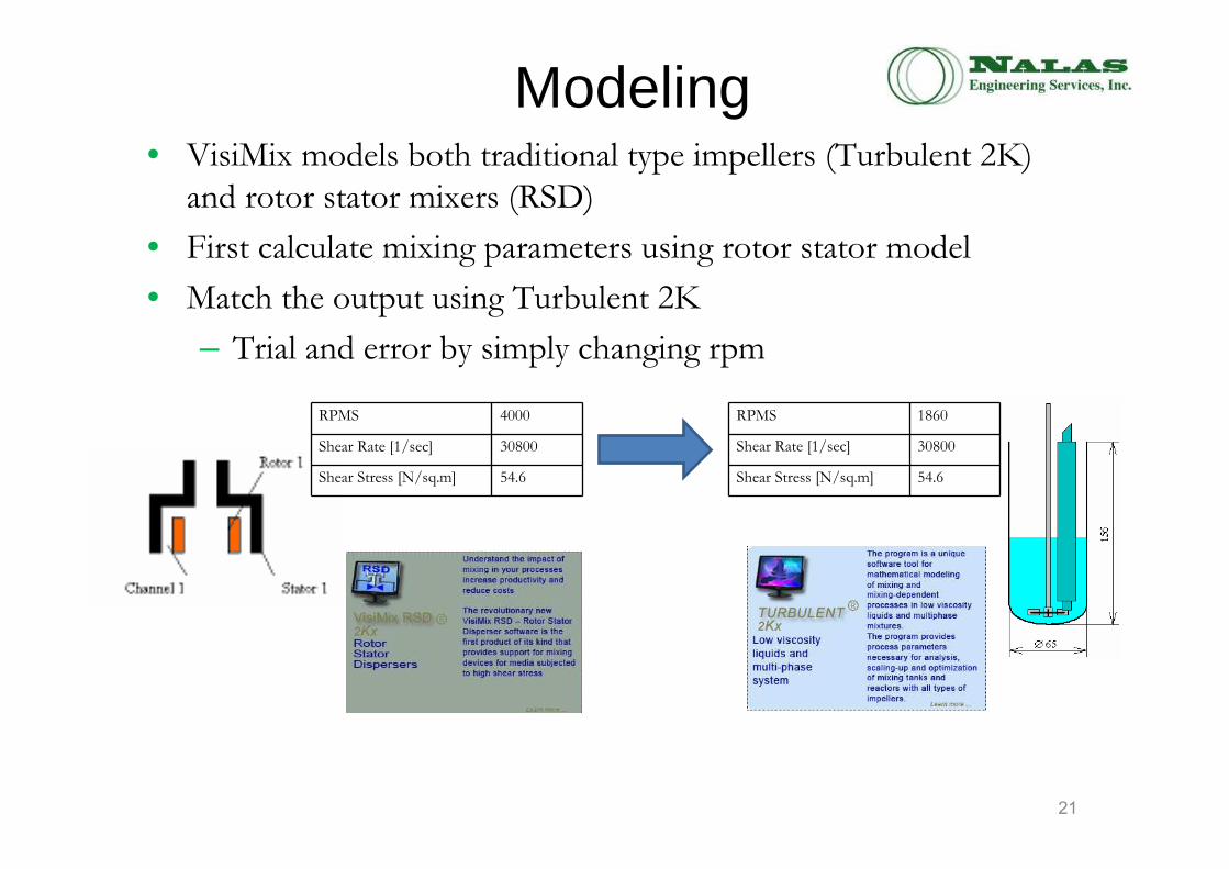
Modeling• VisiMix models both traditional type impellers (Turbulent 2K)
and rotor stator mixers (RSD)
• First calculate mixing parameters using rotor stator model
• Match the output using Turbulent 2K
– Trial and error by simply changing rpm
RPMS 4000
Shear Rate [1/sec] 30800
Shear Stress [N/sq.m] 54.6
RPMS 1860
Shear Rate [1/sec] 30800
Shear Stress [N/sq.m] 54.6
21
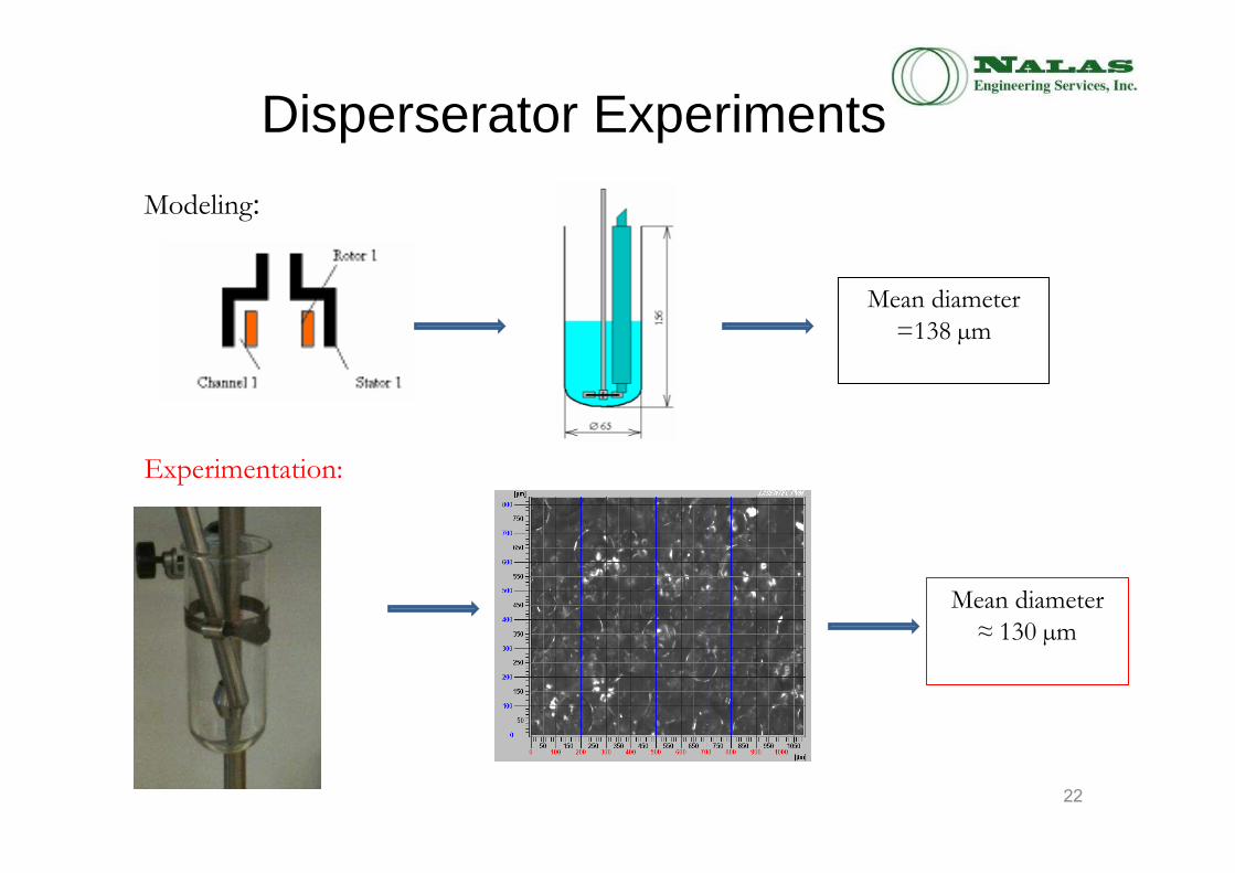
Disperserator Experiments
Mean diameter
=138 µm
Mean diameter
≈ 130 µm
Modeling:
Experimentation:
22
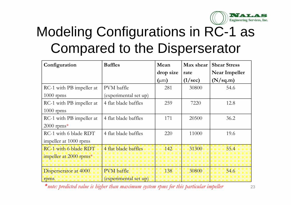
Modeling Configurations in RC-1 as Compared to the Disperserator
23
Configuration Baffles Mean
drop size
(µm)
Max shear
rate
(1/sec)
Shear Stress
Near Impeller
(N/sq.m)
RC-1 with PB impeller at
1000 rpms
PVM baffle
(experimental set up)
281 30800 54.6
RC-1 with PB impeller at
1000 rpms
4 flat blade baffles 259 7220 12.8
RC-1 with PB impeller at
2000 rpms*
4 flat blade baffles 171 20500 36.2
RC-1 with 6 blade RDT
impeller at 1000 rpms
4 flat blade baffles 220 11000 19.6
RC-1 with 6 blade RDT
impeller at 2000 rpms*
4 flat blade baffles 142 31300 55.4
Disperserator at 4000
rpms
PVM baffle
(experimental set up)
138 30800 54.6
*note: predicted value is higher than maximum system rpms for this particular impeller

What we learned from VisiMix about the Reactor Design
• The current RC-1 configuration with a pitched blade impeller does not provide sufficient mixing when compared to the existing
rotor/stator system (to be expected).
• The addition of a RDT gives large improvement as compared to the Pitched Blade Impeller, but with a 1000 rpm limit on the
automated reactor system, still cannot match the dispersator.• If the rpms limit can be increased then it may be possible to use
a RDT in the final configuration.• If not then a disperserator will have to be utilized.
24
VisiMix Model & Mettler Toledo Tools: Scaling-up with Confidence
• Utilization of the in-situ PVM allowed us to validate the VisiMix model giving us confidence in the results and experimental methodology
• VisiMix model provided accurate prediction of mixing parameters for various configurations
• Mettler Toledo tools allowed us to quickly validate the VisiMix models and understand the design aspects of the proposed system– Proposed system will not provide degree of mixing
required without some modifications
25

Conclusions• VisiMix accurately predicts mixing parameters
for both traditional impellers and rotor/stator systems for liquid-liquid mixing
• By modeling the dispersion in the historical laboratory equipment we are able to identify automated reactor configurations that will maintain the same degree of mixing.
26

Acknowledgments
• Mr. Chuck Painter, Director, Navy ManTech Office
• Mr. Patrick Skahan , NSWC Indian Head Division
• Mr. Tod Ricks , NSWC Indian Head Division
• Mrs. Shilpa Amato, NSWC Indian Head Division
• Mr. Jerry Salan and Ms. Shannon Lenahan, Nalas Engineering
27