Embed Size (px)
Citation preview

®
Implants andInstruments
Lubinus SPII®
Anatomically Adapted Total Hip System

WALDEMAR LINK GmbH & Co. KG
Barkhausenweg 10 · D-22339 Hamburg
P. O. Box 63 05 52 · D-22315 Hamburg
Phone +49 (0)40 5 39 95-0
Fax +49 (0)40 5 38 69 29
e-mail [email protected]
Internet www.linkhh.de
1
Contents
Lubinus SPII®
Anatomically Adapted Total Hip System
2 Description
Implants:
4 Prosthesis Stems
12 Prothesis Heads
14 Acetabular Cups
23 Instrument Set for SPII® Prosthesis Stems
34 General Instruments for Implantation of Hip Prostheses
39 Accessories
40 Information
40 Literature
41 Alphabetical and Numerical Index
Important Information
2
Description
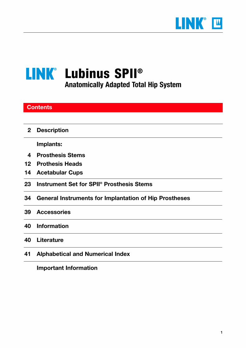
“The 1990-2000 results for Lubinus SP do notsignificantly differ from the 1979-1989 cohortafter 10 years. An explanation for this could bethat the SP stem is “forgiving”and less complicated toinsert in an adequateposition. Well-designed
instruments were also intro-duced early for the Lubinus system.”
Prognosis of Total Hip Replacement. H. Malchau, P. Herberts, G.Garellick, P. Södermann, T. Eisler. Page 6
The anatomically shaped Lubinus SPII® Prosthesis Stem,
developed in 1978 and available as amodular system since 1984, has proven inmore than 20 years to be one of the most
successful cemented hip prosthesis stems.The excellent results have been
supported time and again by the publica-tions of the Swedish Hip Registry.
“The survival function for
cemented implants shows
that the Lubinus SPII® is
still clearly the best,...”
Summery of Annual Report 2002The Swedish National Hip Arthroplasty RegisterApril 2003

3
Description
Outstanding features of the SPII® Hip Stem:
• Minimal bone resection
• Uniform cement mantle around the stem
• Anatomically shaped stem resists rotational forces
• Large collar support achieves reintroduction of physiological forces into the femur
• Built-in physiological anteversion
• Secure reproducible implantation technique
• Modular system allows adjustment to anatomical conditions:
- Two standard and four additional stem lengths of 200 to 350 mm for revisions
- Three CCD neck angles, stems with standard and extra-long neck, and up to four head-neck lengths for exact lateralization and leg length
∅ 12T
∅ 12
T∅ 14
T
∅ 14T
4
Implants
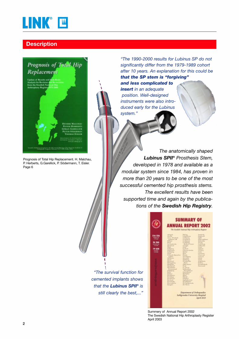
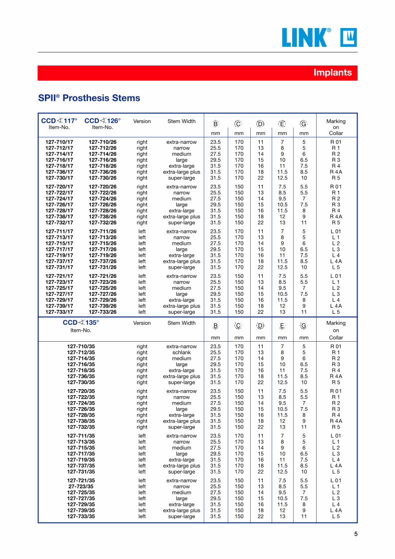
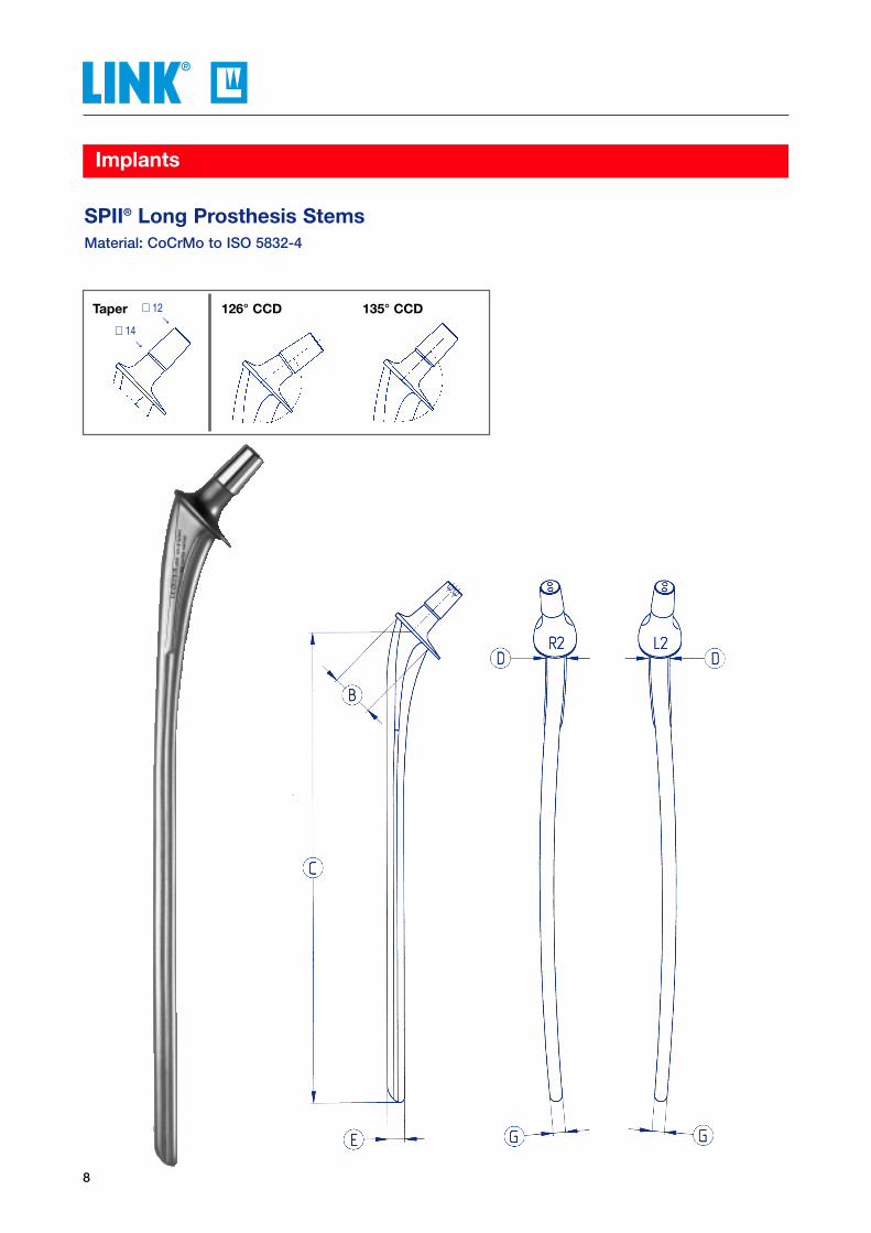
SPII® Prosthesis Stems Material: CoCrMo to ISO 5832-4
117° CCD 126° CCD 135° CCDTaper ∅ 12
∅ 14→
→
5
Implants
CCD 117° CCD 126° Version Stem Width MarkingItem-No. Item-No. on
mm mm mm mm mm Collar
127-710/17 127-710/26 right extra-narrow 23.5 170 11 7 5 R 01127-712/17 127-712/26 right narrow 25.5 170 13 8 5 R 1127-714/17 127-714/26 right medium 27.5 170 14 9 6 R 2127-716/17 127-716/26 right large 29.5 170 15 10 6.5 R 3127-718/17 127-718/26 right extra-large 31.5 170 16 11 7.5 R 4 127-736/17 127-736/26 right extra-large plus 31.5 170 18 11.5 8.5 R 4A127-730/17 127-730/26 right super-large 31.5 170 22 12.5 10 R 5
127-720/17 127-720/26 right extra-narrow 23.5 150 11 7.5 5.5 R 01127-722/17 127-722/26 right narrow 25.5 150 13 8.5 5.5 R 1127-724/17 127-724/26 right medium 27.5 150 14 9.5 7 R 2127-726/17 127-726/26 right large 29.5 150 15 10.5 7.5 R 3127-728/17 127-728/26 right extra-large 31.5 150 16 11.5 8 R 4127-738/17 127-738/26 right extra-large plus 31.5 150 18 12 9 R 4A127-732/17 127-732/26 right super-large 31.5 150 22 13 11 R 5
127-711/17 127-711/26 left extra-narrow 23.5 170 11 7 5 L 01127-713/17 127-713/26 left narrow 25.5 170 13 8 5 L 1127-715/17 127-715/26 left medium 27.5 170 14 9 6 L 2127-717/17 127-717/26 left large 29.5 170 15 10 6.5 L 3127-719/17 127-719/26 left extra-large 31.5 170 16 11 7.5 L 4127-737/17 127-737/26 left extra-large plus 31.5 170 18 11.5 8.5 L 4A127-731/17 127-731/26 left super-large 31.5 170 22 12.5 10 L 5
127-721/17 127-721/26 left extra-narrow 23.5 150 11 7.5 5.5 L 01127-723/17 127-723/26 left narrow 25.5 150 13 8.5 5.5 L 1127-725/17 127-725/26 left medium 27.5 150 14 9.5 7 L 2127-727/17 127-727/26 left large 29.5 150 15 10.5 7.5 L 3127-729/17 127-729/26 left extra-large 31.5 150 16 11.5 8 L 4127-739/17 127-739/26 left extra-large plus 31.5 150 18 12 9 L 4A127-733/17 127-733/26 left super-large 31.5 150 22 13 11 L 5
CCD 135° Version Stem Width MarkingItem-No. on
mm mm mm mm mm Collar
127-710/35 right extra-narrow 23.5 170 11 7 5 R 01127-712/35 right schlank 25.5 170 13 8 5 R 1127-714/35 right medium 27.5 170 14 9 6 R 2127-716/35 right large 29.5 170 15 10 6.5 R 3127-718/35 right extra-large 31.5 170 16 11 7.5 R 4 127-736/35 right extra-large plus 31.5 170 18 11.5 8.5 R 4A127-730/35 right super-large 31.5 170 22 12.5 10 R 5
127-720/35 right extra-narrow 23.5 150 11 7.5 5.5 R 01127-722/35 right narrow 25.5 150 13 8.5 5.5 R 1127-724/35 right medium 27.5 150 14 9.5 7 R 2127-726/35 right large 29.5 150 15 10.5 7.5 R 3127-728/35 right extra-large 31.5 150 16 11.5 8 R 4127-738/35 right extra-large plus 31.5 150 18 12 9 R 4A127-732/35 right super-large 31.5 150 22 13 11 R 5
127-711/35 left extra-narrow 23.5 170 11 7 5 L 01127-713/35 left narrow 25.5 170 13 8 5 L 1127-715/35 left medium 27.5 170 14 9 6 L 2127-717/35 left large 29.5 170 15 10 6.5 L 3127-719/35 left extra-large 31.5 170 16 11 7.5 L 4127-737/35 left extra-large plus 31.5 170 18 11.5 8.5 L 4A127-731/35 left super-large 31.5 170 22 12.5 10 L 5
127-721/35 left extra-narrow 23.5 150 11 7.5 5.5 L 0127-723/35 left narrow 25.5 150 13 8.5 5.5 L 1127-725/35 left medium 27.5 150 14 9.5 7 L 2127-727/35 left large 29.5 150 15 10.5 7.5 L 3127-729/35 left extra-large 31.5 150 16 11.5 8 L 4127-739/35 left extra-large plus 31.5 150 18 12 9 L 4A127-733/35 left super-large 31.5 150 22 13 11 L 5
SPII® Prosthesis Stems
B C D E G
B C D E G

6
Implants
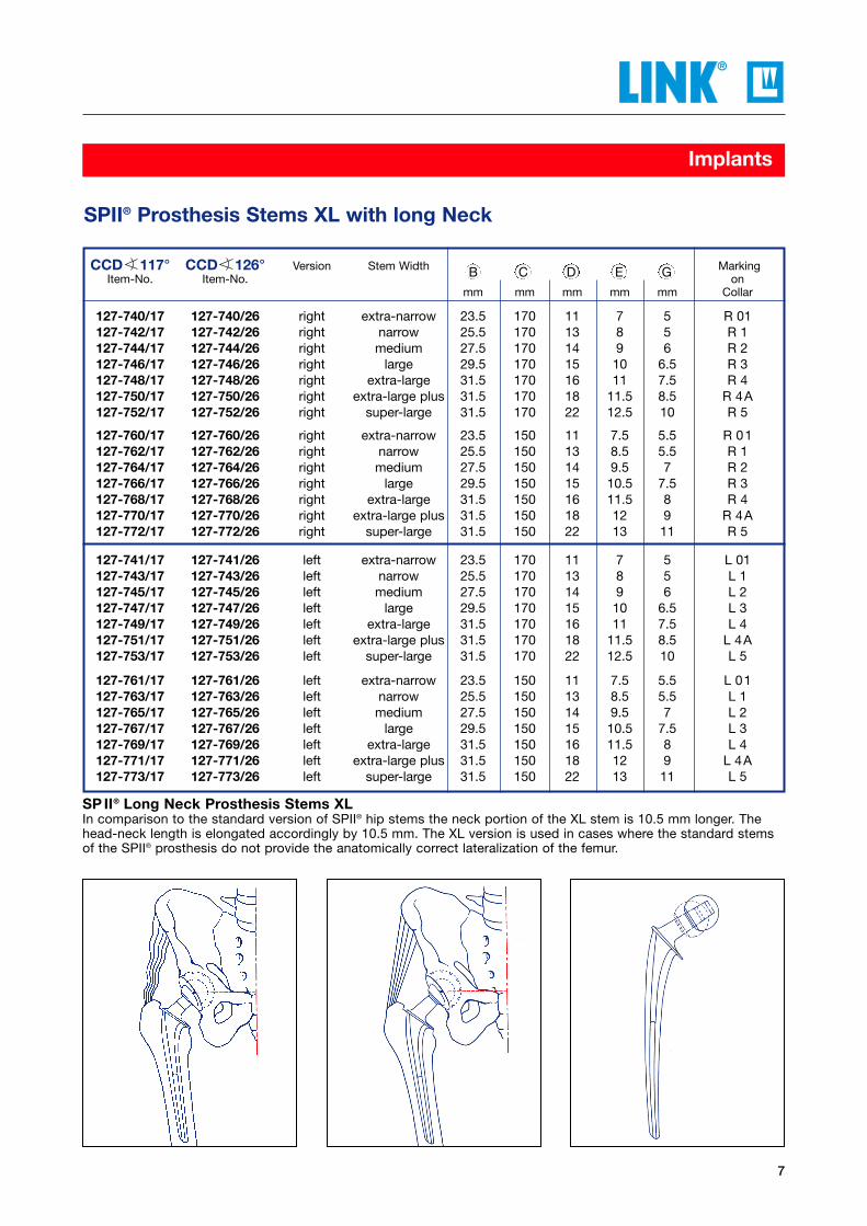
SPII® Prosthesis Stems XL with long NeckMaterial: CoCrMo to ISO 5832-4
117° CCD 126° CCDTaper∅ 12→
→∅ 14
7
Implants
Literatur Literature
CCD 117° CCD 126° Version Stem Width MarkingItem-No. Item-No. on
mm mm mm mm mm Collar
127-740/17 127-740/26 right extra-narrow 23.5 170 11 7 5 R 01127-742/17 127-742/26 right narrow 25.5 170 13 8 5 R 1127-744/17 127-744/26 right medium 27.5 170 14 9 6 R 2127-746/17 127-746/26 right large 29.5 170 15 10 6.5 R 3127-748/17 127-748/26 right extra-large 31.5 170 16 11 7.5 R 4 127-750/17 127-750/26 right extra-large plus 31.5 170 18 11.5 8.5 R 4A127-752/17 127-752/26 right super-large 31.5 170 22 12.5 10 R 5
127-760/17 127-760/26 right extra-narrow 23.5 150 11 7.5 5.5 R 01127-762/17 127-762/26 right narrow 25.5 150 13 8.5 5.5 R 1127-764/17 127-764/26 right medium 27.5 150 14 9.5 7 R 2127-766/17 127-766/26 right large 29.5 150 15 10.5 7.5 R 3127-768/17 127-768/26 right extra-large 31.5 150 16 11.5 8 R 4127-770/17 127-770/26 right extra-large plus 31.5 150 18 12 9 R 4A127-772/17 127-772/26 right super-large 31.5 150 22 13 11 R 5
127-741/17 127-741/26 left extra-narrow 23.5 170 11 7 5 L 01127-743/17 127-743/26 left narrow 25.5 170 13 8 5 L 1127-745/17 127-745/26 left medium 27.5 170 14 9 6 L 2127-747/17 127-747/26 left large 29.5 170 15 10 6.5 L 3127-749/17 127-749/26 left extra-large 31.5 170 16 11 7.5 L 4127-751/17 127-751/26 left extra-large plus 31.5 170 18 11.5 8.5 L 4A127-753/17 127-753/26 left super-large 31.5 170 22 12.5 10 L 5
127-761/17 127-761/26 left extra-narrow 23.5 150 11 7.5 5.5 L 01127-763/17 127-763/26 left narrow 25.5 150 13 8.5 5.5 L 1127-765/17 127-765/26 left medium 27.5 150 14 9.5 7 L 2127-767/17 127-767/26 left large 29.5 150 15 10.5 7.5 L 3127-769/17 127-769/26 left extra-large 31.5 150 16 11.5 8 L 4127-771/17 127-771/26 left extra-large plus 31.5 150 18 12 9 L 4A127-773/17 127-773/26 left super-large 31.5 150 22 13 11 L 5
SPII® Prosthesis Stems XL with long Neck
B C D E G
SP II® Long Neck Prosthesis Stems XLIn comparison to the standard version of SPII® hip stems the neck portion of the XL stem is 10.5 mm longer. Thehead-neck length is elongated accordingly by 10.5 mm. The XL version is used in cases where the standard stemsof the SPII® prosthesis do not provide the anatomically correct lateralization of the femur.
8
Implants
SPII® Long Prosthesis StemsMaterial: CoCrMo to ISO 5832-4
126° CCDTaper 135° CCD∅ 12→
→∅ 14
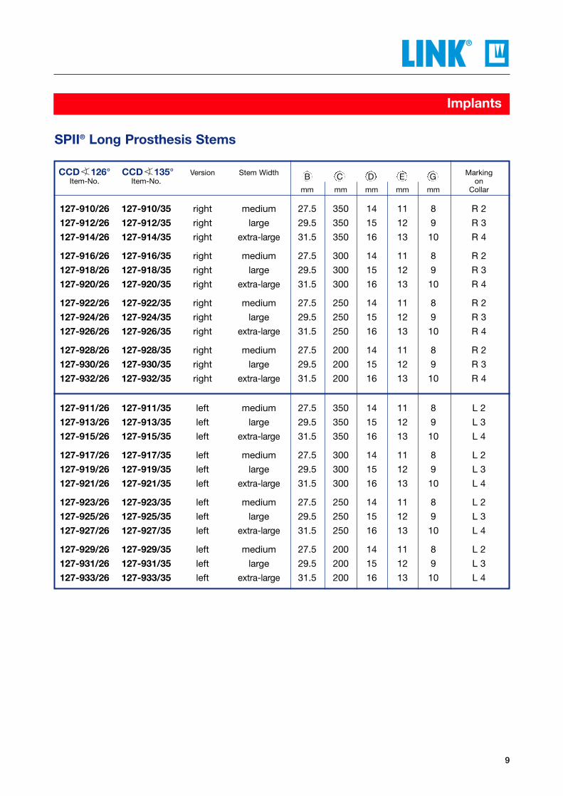
CCD 126° CCD 135° Version Stem Width MarkingItem-No. Item-No. on
mm mm mm mm mm Collar
127-910/26 127-910/35 right medium 27.5 350 14 11 8 R 2
127-912/26 127-912/35 right large 29.5 350 15 12 9 R 3
127-914/26 127-914/35 right extra-large 31.5 350 16 13 10 R 4
127-916/26 127-916/35 right medium 27.5 300 14 11 8 R 2
127-918/26 127-918/35 right large 29.5 300 15 12 9 R 3
127-920/26 127-920/35 right extra-large 31.5 300 16 13 10 R 4
127-922/26 127-922/35 right medium 27.5 250 14 11 8 R 2
127-924/26 127-924/35 right large 29.5 250 15 12 9 R 3
127-926/26 127-926/35 right extra-large 31.5 250 16 13 10 R 4
127-928/26 127-928/35 right medium 27.5 200 14 11 8 R 2
127-930/26 127-930/35 right large 29.5 200 15 12 9 R 3
127-932/26 127-932/35 right extra-large 31.5 200 16 13 10 R 4
127-911/26 127-911/35 left medium 27.5 350 14 11 8 L 2
127-913/26 127-913/35 left large 29.5 350 15 12 9 L 3
127-915/26 127-915/35 left extra-large 31.5 350 16 13 10 L 4
127-917/26 127-917/35 left medium 27.5 300 14 11 8 L 2
127-919/26 127-919/35 left large 29.5 300 15 12 9 L 3
127-921/26 127-921/35 left extra-large 31.5 300 16 13 10 L 4
127-923/26 127-923/35 left medium 27.5 250 14 11 8 L 2
127-925/26 127-925/35 left large 29.5 250 15 12 9 L 3
127-927/26 127-927/35 left extra-large 31.5 250 16 13 10 L 4
127-929/26 127-929/35 left medium 27.5 200 14 11 8 L 2
127-931/26 127-931/35 left large 29.5 200 15 12 9 L 3
127-933/26 127-933/35 left extra-large 31.5 200 16 13 10 L 4
9
Implants
SPII® Long Prosthesis Stems
B C D E G

10
Implants
SPII® Prosthesis Stems of Tilastan® for metal-allergic patientsMaterial: Ti-6Al-4V to ISO 5832-3, ASTM F136
126° CCD 135° CCDTaper ∅ 12
∅ 14→
→
11
Implants
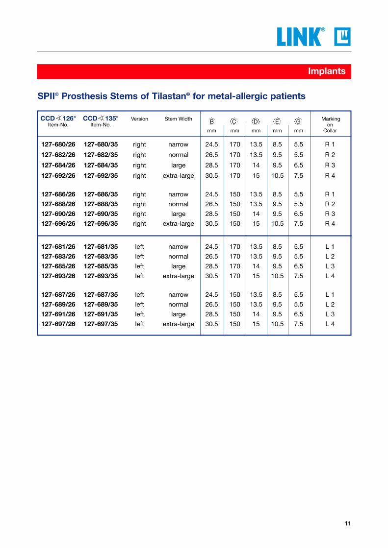
SPII® Prosthesis Stems of Tilastan® for metal-allergic patients
CCD 126° CCD 135° Version Stem Width MarkingItem-No. Item-No. on
mm mm mm mm mm Collar
127-680/26 127-680/35 right narrow 24.5 170 13.5 8.5 5.5 R 1
127-682/26 127-682/35 right normal 26.5 170 13.5 9.5 5.5 R 2
127-684/26 127-684/35 right large 28.5 170 14 9.5 6.5 R 3
127-692/26 127-692/35 right extra-large 30.5 170 15 10.5 7.5 R 4
127-686/26 127-686/35 right narrow 24.5 150 13.5 8.5 5.5 R 1
127-688/26 127-688/35 right normal 26.5 150 13.5 9.5 5.5 R 2
127-690/26 127-690/35 right large 28.5 150 14 9.5 6.5 R 3
127-696/26 127-696/35 right extra-large 30.5 150 15 10.5 7.5 R 4
127-681/26 127-681/35 left narrow 24.5 170 13.5 8.5 5.5 L 1
127-683/26 127-683/35 left normal 26.5 170 13.5 9.5 5.5 L 2
127-685/26 127-685/35 left large 28.5 170 14 9.5 6.5 L 3
127-693/26 127-693/35 left extra-large 30.5 170 15 10.5 7.5 L 4
127-687/26 127-687/35 left narrow 24.5 150 13.5 8.5 5.5 L 1
127-689/26 127-689/35 left normal 26.5 150 13.5 9.5 5.5 L 2
127-691/26 127-691/35 left large 28.5 150 14 9.5 6.5 L 3
127-697/26 127-697/35 left extra-large 30.5 150 15 10.5 7.5 L 4
B C D E G

12
Implants
128-760 46 28 short128-761 49.5 28 medium-short128-762 53 28 medium
128-768 47.5 32 short128-769 51.5 32 medium-short128-770 55.5 32 medium
Prosthesis Heads A - Biolox®forteMaterial: *Biolox®forte Aluminium Oxide Ceramic to ISO 6474, ASTM F603
forItem-No. Head-Neck Length # Head-∅ Neck Length
mm mm
∅ 28 mm
Taper 12/14 mm 46 mm 49.5 mm 53 mm
∅ 32 mm
Taper 12/14 mm 47.5 mm 51.5 mm 55.5 mm
Prosthesis Heads B - CoCrMoMaterial: CoCrMo to ISO 5832-4, ASTM F75
forItem-No. Head-Neck Length # Head-∅ Neck Length
mm mm
∅ 22 mmTaper 12/14 mm 46 mm 49.5 mm
∅ 24 mmTaper 12/14 mm 46 mm 49.5 mm
∅ 28 mmTaper12/14 mm 46 mm 49.5 mm 53 mm 60 m
∅ 32 mmTaper 12/14 mm 47.5 mm 51.5 mm 55.5 mm 60 mm
* Biolox®forte is a product of CeramTec, Plochingen, Germany
# In combination with XL stems 10.5 mm have to be added
128-744 46 22 short128-745 49.5 22 medium-short
128-743/46 46 24 short128-743/49 49.5 24 medium-short
128-746 46 28 short128-747 49.5 28 medium-short128-748 53 28 medium128-783 60 28 long
128-754 47.5 32 short128-755 51.5 32 medium-short128-756 55.5 32 medium128-787 60 32 long
# In combination with XL stems 10.5 mm have to be added
For Taper 12/14 mm
∅ 12→→∅ 14
For Taper 12/14 mm
∅ 12→→∅ 14
13
Implants
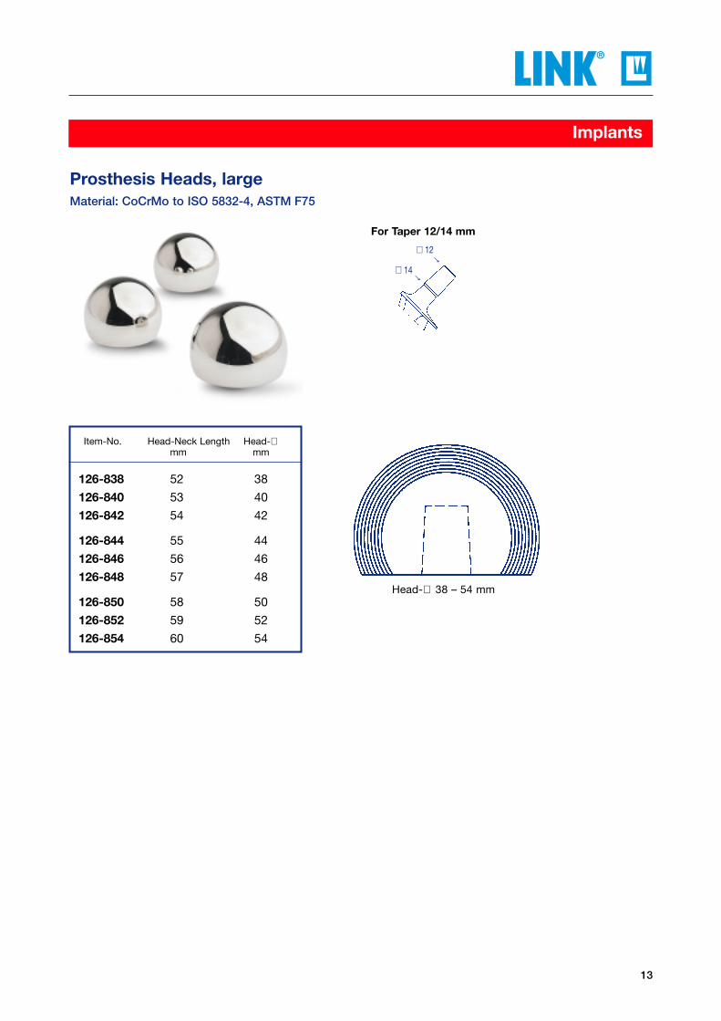
Prosthesis Heads, largeMaterial: CoCrMo to ISO 5832-4, ASTM F75
Item-No. Head-Neck Length Head-∅mm mm
126-838 52 38
126-840 53 40
126-842 54 42
126-844 55 44
126-846 56 46
126-848 57 48
126-850 58 50
126-852 59 52
126-854 60 54
Head-∅ 38 – 54 mm
For Taper 12/14 mm
∅ 12→
→∅ 14

14
Implants
Lubinus Eccentric Acetabular CupsMaterial: UHMWPE to ISO 5834-2, ASTM F648
101-102 101-122 28 44101-104 101-124 28 46101-106 101-126 28 48101-108 101-128 28 50101-110 101-130 28 52101-112 101-132 28 54101-114 101-134 28 56101-116 101-136 28 58
102-102 102-122 32 44102-104 102-124 32 46102-106 102-126 32 48102-108 102-128 32 50102-110 102-130 32 52102-112 102-132 32 54102-114 102-134 32 56102-116 102-136 32 58
Inner-∅Outer-∅
with withoutSnap-fit Snap-fit Inner-∅ 28.5 mm Inner-∅ 32.5 mmItem-No. Item-No. For Head-∅ Outer-∅ For Head-∅ Outer-∅
mm mm mm mm
The Lubinus Eccentric Acetabular Cups are supplied in 8 outer diameters, ranging from 44 to 58 mm, in 2 mmincrements. In addition, 2 inner diameters of 28.5 and 32.5 are offered for each of the outer diameters. Because theinner surface of the cup envelops more than 50% of the head of the hip stem, the danger of dislocation is less thanthat of ordinary acetabular components. This is an especially important consideration during the critical early post-operative stage.
The eccentric design of the acetabular component allows for maximum material thickness in the load area. Moreover,the 0.5 mm play between the head of the prosthesis and the acetabular cup accommodates advantageous lubricatingfunctions.
Spacers about the outer profile of the cup assure a uniform mantle of cement at the time of implantation. In addition,vertical and horizontal grooves at the surface provide for optimal fixation of the cup with bone cement. Most acetabulacan thus be treated with an implant of sufficient wall thickness.
Accessories: 130-924 X-ray Template, 110% actual size, 2 sheets
15
Implants
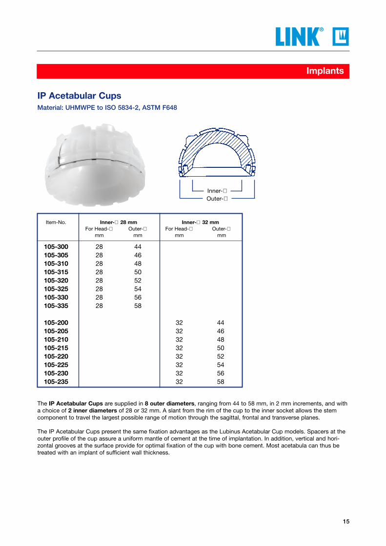
IP Acetabular CupsMaterial: UHMWPE to ISO 5834-2, ASTM F648
105-300 28 44105-305 28 46105-310 28 48105-315 28 50105-320 28 52105-325 28 54105-330 28 56105-335 28 58
105-200 32 44105-205 32 46105-210 32 48105-215 32 50105-220 32 52105-225 32 54105-230 32 56105-235 32 58
Inner-∅Outer-∅
Item-No. Inner-∅ 28 mm Inner-∅ 32 mmFor Head-∅ Outer-∅ For Head-∅ Outer-∅
mm mm mm mm
The IP Acetabular Cups are supplied in 8 outer diameters, ranging from 44 to 58 mm, in 2 mm increments, and witha choice of 2 inner diameters of 28 or 32 mm. A slant from the rim of the cup to the inner socket allows the stemcomponent to travel the largest possible range of motion through the sagittal, frontal and transverse planes.
The IP Acetabular Cups present the same fixation advantages as the Lubinus Acetabular Cup models. Spacers at theouter profile of the cup assure a uniform mantle of cement at the time of implantation. In addition, vertical and hori-zontal grooves at the surface provide for optimal fixation of the cup with bone cement. Most acetabula can thus betreated with an implant of sufficient wall thickness.
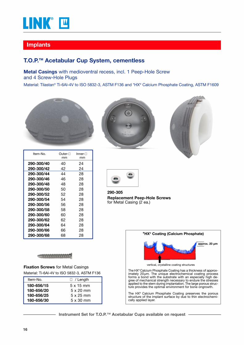
The HX® Calcium Phosphate Coating has a thickness of approx-imately 20µm. The unique electrochemical coating processforms a bond with the substrate with an especially high de-gree of mechanical strength necessary to endure the stressesapplied to the stem during implantation. The large porous struc-ture provides the optimal environment for bone ongrowth.
The HX® Calcium Phosphate Coating preserves the porousstructure of the implant surface by due to thin electrochemi-cally applied layer.
*HX® Coating (Calcium Phosphate)
vertical, crystalline coating structures
approx. 20 µm
Instrument Set for T.O.P.™ Acetabular Cups available on request
16
Implants
Fixation Screws for Metal CasingsMaterial: Ti-6Al-4V to ISO 5832-3, ASTM F136
Item-No. ∅ / Length
180-656/15 5 x 15 mm180-656/20 5 x 20 mm180-656/25 5 x 25 mm180-656/30 5 x 30 mm
290-300/40 40 24290-300/42 42 24290-300/44 44 28290-300/46 46 28290-300/48 48 28290-300/50 50 28290-300/52 52 28290-300/54 54 28290-300/56 56 28290-300/58 58 28290-300/60 60 28290-300/62 62 28290-300/64 64 28290-300/66 66 28290-300/68 68 28
Metal Casings with medioventral recess, incl. 1 Peep-Hole Screw and 4 Screw-Hole PlugsMaterial: Tilastan® Ti-6Al-4V to ISO 5832-3, ASTM F136 and *HX® Calcium Phosphate Coating, ASTM F1609
T.O.P.TM Acetabular Cup System, cementless
Item-No. Outer-∅ Inner-∅mm mm
290-305Replacement Peep-Hole Screwsfor Metal Casing (2 ea.)

17
Implants
T.O.P.™ Acetabular Cup System, cementless
T.O.P.™ Polyethylene Inserts, anti-luxationMaterial: UHMWPE to ISO 5834-2, ASTM F648
Item-No. for Metal Casings Outer-∅ Inner-∅mm mm
290-320/40 40 24290-320/42 42 24
290-321/44 44 28290-321/46 46 28290-321/48 48 28290-321/50 50 28290-321/52 52 28290-321/54 54 28290-321/56 56 28290-321/58 58 28290-321/60 60 28290-321/62 62 28290-321/64 64 28290-321/66 66 28290-321/68 68 28
Item-No. for Metal Casings Outer-∅ Inner-∅mm mm
Inner-∅
Inner-∅
180-750/40 40 24180-750/42 42 24
180-751/44 44 28180-751/46 46 28180-751/48 48 28180-751/50 50 28180-751/52 52 28180-751/54 54 28180-751/56 56 28180-751/58 58 28180-751/60 60 28180-751/62 62 28180-751/64 64 28180-751/66 66 28180-751/68 68 28
Polyethylene Inserts, standard Material: UHMWPE to ISO 5834-2, ASTM F648
Instrument Set for T.O.P.™ Acetabular Cups available on request
18
Implants
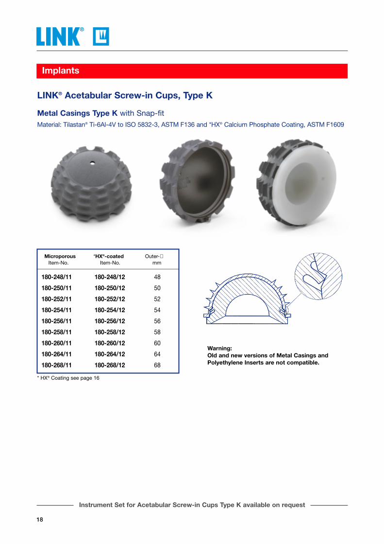
Metal Casings Type K with Snap-fitMaterial: Tilastan® Ti-6Al-4V to ISO 5832-3, ASTM F136 and *HX® Calcium Phosphate Coating, ASTM F1609
LINK® Acetabular Screw-in Cups, Type K
180-248/11 180-248/12 48
180-250/11 180-250/12 50
180-252/11 180-252/12 52
180-254/11 180-254/12 54
180-256/11 180-256/12 56
180-258/11 180-258/12 58
180-260/11 180-260/12 60
180-264/11 180-264/12 64
180-268/11 180-268/12 68
Microporous *HX®-coated Outer-∅Item-No. Item-No. mm
Warning: Old and new versions of Metal Casings andPolyethylene Inserts are not compatible.
* HX® Coating see page 16
Instrument Set for Acetabular Screw-in Cups Type K available on request
19
Implants
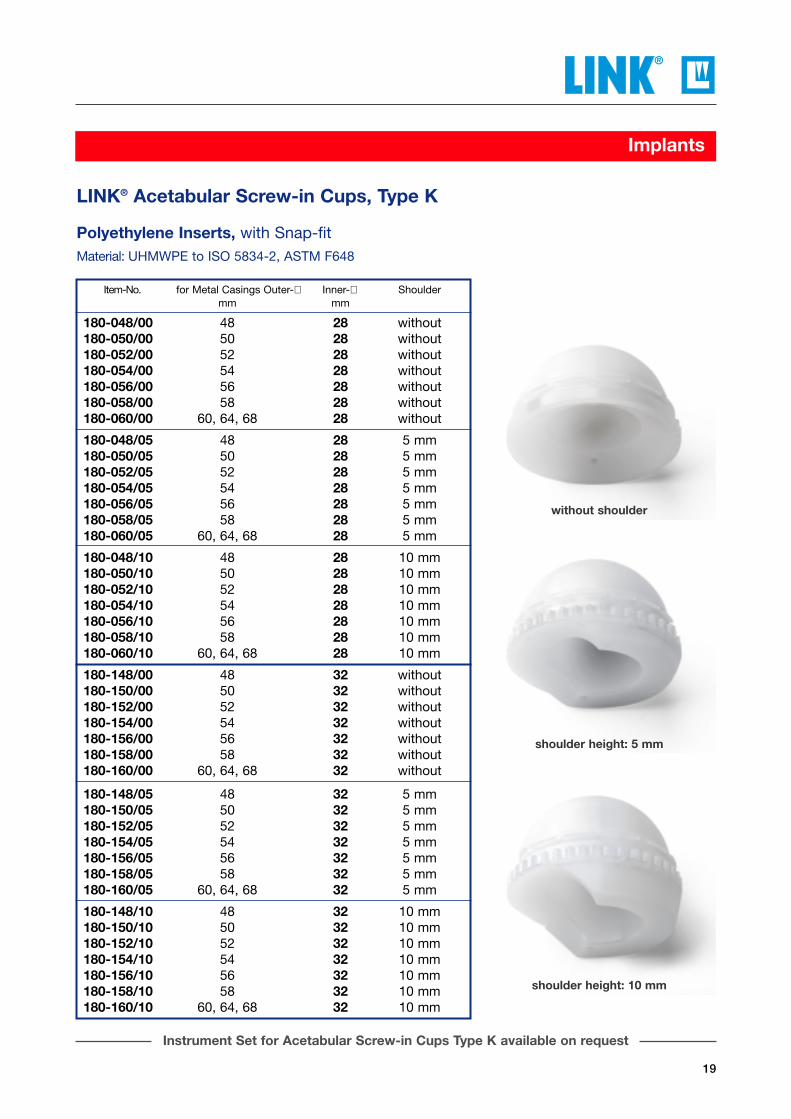
Polyethylene Inserts, with Snap-fitMaterial: UHMWPE to ISO 5834-2, ASTM F648
LINK® Acetabular Screw-in Cups, Type K
Item-No. for Metal Casings Outer-∅ Inner-∅ Shouldermm mm
180-048/00 48 28 without180-050/00 50 28 without180-052/00 52 28 without180-054/00 54 28 without180-056/00 56 28 without180-058/00 58 28 without180-060/00 60, 64, 68 28 without
180-048/05 48 28 5 mm180-050/05 50 28 5 mm180-052/05 52 28 5 mm180-054/05 54 28 5 mm180-056/05 56 28 5 mm180-058/05 58 28 5 mm180-060/05 60, 64, 68 28 5 mm
180-048/10 48 28 10 mm180-050/10 50 28 10 mm180-052/10 52 28 10 mm180-054/10 54 28 10 mm180-056/10 56 28 10 mm180-058/10 58 28 10 mm180-060/10 60, 64, 68 28 10 mm
180-148/00 48 32 without180-150/00 50 32 without180-152/00 52 32 without180-154/00 54 32 without180-156/00 56 32 without180-158/00 58 32 without180-160/00 60, 64, 68 32 without
180-148/05 48 32 5 mm180-150/05 50 32 5 mm180-152/05 52 32 5 mm180-154/05 54 32 5 mm180-156/05 56 32 5 mm180-158/05 58 32 5 mm180-160/05 60, 64, 68 32 5 mm
180-148/10 48 32 10 mm180-150/10 50 32 10 mm180-152/10 52 32 10 mm180-154/10 54 32 10 mm180-156/10 56 32 10 mm180-158/10 58 32 10 mm180-160/10 60, 64, 68 32 10 mm
without shoulder
shoulder height: 5 mm
shoulder height: 10 mm
Instrument Set for Acetabular Screw-in Cups Type K available on request

20
Implants
Metal Casings Type VMaterial: Tilastan® Ti-6Al-4V to ISO 5832-3, ASTM F136 and *HX® Calcium Phosphate Coating, ASTM F1609
LINK® Acetabular Screw-in Cups, Type V
180-540/01 180-540/02 40
180-542/01 180-542/02 42
180-544/01 180-544/02 44
180-546/01 180-546/02 46
180-548/01 180-548/02 48
180-550/01 180-550/02 50
180-552/01 180-552/02 52
180-554/01 180-554/02 54
180-556/01 180-556/02 56
180-558/01 180-558/02 58
180-560/01 180-560/02 60
180-564/01 180-564/02 64
180-568/01 180-568/02 68
Microporous *HX®-coated Outer-∅Item-No. Item-No. mm
Outer-∅
* HX® Coating see page 16
Instrument Set for Acetabular Screw-in Cups Type V available on request

21
Implants
LINK® Acetabular Screw-in Cups, Type V
Lid Lid for Metal Casing microporous HX®-coated Outer-∅ Inner-∅ Shoulder
Item-No. Item-No. mm mm
180-721/11 180-721/12 40 22 without180-722/11 180-722/12 42 22 without
180-724/11 180-724/12 44 24 without180-726/11 180-726/12 46 24 without
180-669/01 180-669/02 48 28 without180-671/01 180-671/02 50 28 without180-673/01 180-673/02 52 28 without180-675/01 180-675/02 54 28 without180-677/01 180-677/02 56 28 without180-679/01 180-679/02 58 28 without180-681/01 180-681/02 60, 64, 68 28 without
180-731/11 180-731/12 40 22 5 mm180-732/11 180-732/12 42 22 5 mm
180-734/11 180-734/12 44 24 5 mm180-736/11 180-736/12 46 24 5 mm
180-689/01 180-689/02 48 28 5 mm180-691/01 180-691/02 50 28 5 mm180-693/01 180-693/02 52 28 5 mm180-695/01 180-695/02 54 28 5 mm180-697/01 180-697/02 56 28 5 mm180-699/01 180-699/02 58 28 5 mm180-701/01 180-701/02 60, 64, 68 28 5 mm
180-741/11 180-741/12 40 22 10 mm180-742/11 180-742/12 42 22 10 mm
180-744/11 180-744/12 44 24 10 mm180-746/11 180-746/12 46 24 10 mm
180-709/01 180-709/02 48 28 10 mm180-711/01 180-711/02 50 28 10 mm180-713/01 180-713/02 52 28 10 mm180-715/01 180-715/02 54 28 10 mm180-717/01 180-717/02 56 28 10 mm180-719/01 180-719/02 58 28 10 mm180-719/05 180-719/06 60, 64, 68 28 10 mm
shoulder height: 10 mm
shoulder height: 5 mm
without shoulder
Polyethylene Inserts, with Tilastan® Lid, for Metal CasingsMaterial: UHMWPE to ISO 5834-2, ASTM F648, Ti-6Al-4V to ISO 5832-3
Polyethylene Inserts with anti-luxation shoulder and cobalt-chromium alloy x-ray wire.
Instrument Set for Acetabular Screw-in Cups Type V available on request

22
Implants
LINK® Vario-Cup Prostheses, self-centeringMaterial: CoCrMo to ISO 5832-4, ASTM F75 and UHMWPE to ISO 5834-2, ASTM F648
* without safety ring# not self-centering
Inner-∅ (d) Inner-∅ (d) Inner-∅ (d)24,1 mm 28,1 mm 32,1 mm Outer-∅ (D)Item-No. Item-No. Item-No. mm
107-210/39*# 39107-210/40*# 40
107-210/41* 41107-210/42* 42107-210/43* 00 43
107-220/44 44107-220/45 45107-220/46 46
107-220/47 00 47107-220/48 0 48107-220/49 107-230/49 49
107-220/50 107-230/50 50107-220/51 107-230/51 51107-220/52 107-230/52 52
107-220/53 107-230/53 53107-220/54 107-230/54 54107-220/55 107-230/55 55
107-220/56 107-230/56 56107-220/57 107-230/57 57107-220/58 107-230/58 58
107-220/59 107-230/59 59107-220/60 107-230/60 60107-220/61 107-230/61 61
107-220/62 107-230/62 62107-220/63 107-230/63 63107-220/64 107-230/64 64
107-220/65 107-230/65 65
∅ D
∅ d
Accessories: 130-915/02 x-ray Template, 110% actual size, 2 sheets

23
Instrument Set
SPII® Instrument Set, completein 2 Containers on 3 Trays with storage inserts
Content:
130-408C Handle for Calcar Reamer Fitting optional, see page 25 C=Harris 1 ea.
131-597 Impactor 1 ea.
130-600 Driver for Prosthesis Heads 1 ea.
130-959 Head Remover 1 ea.
131-830/01 Inserting Forceps for modular stems 1 ea.
130-406/01A Calcar Reamer, ∅ 40 mm Fitting optional, see page 25 A=Jacobs Chuck 1 ea.
05-2003/03 N31 Standard Container575 x 275 x 170 mm 1 ea.
130-899/58 Lower Tray only, perforated Stainless Steel, with product illustrations 550 x 265 x 50 mm 1 ea.
130-899/59 Upper Tray only, perforated StainlessSteel, with product illustrations 550 x 265 x 50 mm 1 ea.
Item-No. Taper Head-∅ Stem Lengthmm mm mm
130-899/70 12/14 28 150
130-899/71 12/14 28 170
130-899/80 12/14 32 150
130-899/81 12/14 32 170
The contents of theInstrument Sets dependson the Head Diameter and Stem Length.
Container 1 - Taper 12/14 mm -optional:
130-899/72 Head-∅ 28 mm
130-899/82 Head-∅ 32 mm
consisting of:
Instrument Set, complete, for SPII® Prosthesis Stems
Container 1
Container 2
24
Instrument Set
05-2001/03 N11 Standard Container575 x 275 x 100 mm 1 ea.
130-899/68 Tray only, perforated Stainless Steel with product illustrations 550 x 265 x 50 mm 1 ea.
Content:
Rasp Stems for Prostheses of CoCrMo Alloy
Stem Length 150 mm:130-957/65 right extra-narrow 1 ea.130-957/60 right narrow 1 ea.130-952/60 right medium 1 ea.130-946/60 right large 1 ea.130-942/60 right extra-large 1 ea.130-942/65 right extra-large plus 1 ea.130-949/60 right super-large 1 ea.
130-958/65 left extra-narrow 1 ea.130-958/60 left narrow 1 ea.130-953/60 left medium 1 ea.130-947/60 left large 1 ea.130-943/60 left extra-large 1 ea.130-943/65 left extra-large plus 1 ea.130-949/61 left super-large 1 ea.
optional:
Stem Length 170 mm:130-955/65 right extra-narrow 1 ea.130-955/60 right narrow 1 ea.130-950/60 right medium 1 ea.130-944/60 right large 1 ea.130-940/60 right extra-large 1 ea.130-940/65 right extra-large plus 1 ea.130-948/60 right super-large 1 ea.
130-956/65 left extra-narrow 1 ea.130-956/60 left narrow 1 ea.130-951/60 left medium 1 ea.130-945/60 left large 1 ea.130-941/60 left extra-large 1 ea.130-941/65 left extra-large plus 1 ea.130-948/61 left super-large 1 ea.
Container 2 - Taper 12/14 mm -optional:
130-899/83 150 mm Stem Length
130-899/84 170 mm Stem Length
consisting of:
Femoral Reamers, flexible, 250 mmFitting optional, see page 25 E=Jacobs Chuck
130-360E ∅ 8 mm 1 ea.130-368E ∅ 9 mm 1 ea.130-361E ∅ 10 mm 1 ea.130-362E ∅ 11 mm 1 ea.130-363E ∅ 12 mm 1 ea.130-364E ∅ 13 mm 1 ea.130-365E ∅ 14 mm 1 ea.
Trial Neck Sections with pin and snap-fit
131-520/17 117° CCD right 1 ea.131-521/17 117° CCD left 1 ea.131-520/26 126° CCD right 1 ea.131-521/26 126° CCD left 1 ea.131-520/35 135° CCD right 1 ea.131-521/35 135° CCD left 1 ea.
Trial Heads for Taper 12/14 mm
Head-∅ Head-Neck Length
131-528/46 28 mm 46 mm 1 ea.131-528/49 28 mm 49.5 mm 1 ea.131-528/53 28 mm 53 mm 1 ea.131-528/60 28 mm 60 mm 1 ea.
optional:
131-532/47 32 mm 47.5 mm 1 ea.131-532/51 32 mm 51.5 mm 1 ea.131-532/55 32 mm 55.5 mm 1 ea.131-532/60 32 mm 60 mm 1 ea.
Colored Plastic Trial Headsfor Taper 12/14 mm
Head-∅ Head-Neck Length
28 mm 46 mm131-536 28 mm 49.5 mm 1 Set
28 mm 53 mm
131-536/60 28 mm 60 mm 1 ea.
optional:
32 mm 47.5 mm131-537 32 mm 51.5 mm 1 Set
32 mm 55.5 mm
131-537/60 32 mm 60 mm 1 ea.
130-393/60 Handle for Rasp Stems 1 ea.
10-5373 Hex Screwdriver hex. 2.5 mm, 180 mm, for 130-393/60 1 ea.
130-608/01 Stem Extractor for Taper 12/14 mm 1 ea.
130-609 Hex Screwdriver 1 ea.
130-611 Impactor 1 ea.

25
Instrument Set
Femoral Reamers, flexible for preparation offemoral canal, 250 mm,
Fitting optional: Hudson B, Harris C, AO D,Jacobs Chuck E, Trinkle F(How to order: 130-368B = with Hudson Fitting)
Item-No. ∅130-360 8 mm (front cutting)
130-368 9 mm130-361 10 mm130-362 11 mm130-363 12 mm (side cutting)130-364 13 mm130-365 14 mm130-367 16 mm
Calcar Reamers to plane resection surface, ∅ 40 mm and 46 mm
Fitting optional: Jacobs Chuck A, Hudson B, Harris C, AO D(How to order: 130-406/01D = with AO Fitting)
Item-No. Reamer-∅130-406/01 40 mm175-606/01* 46 mm
130-959Head Removerfor removing modularheads
131-830/01Inserting Forcepsfor modular stems200 mm
130-600Driver for ProsthesisHeadswith exchangeable plasticheads, 170 mm
130-408Handle for Calcar Reamer300 mmFitting optional: JacobsChuck A, Hudson B, Harris C, AO D(How to order: 130-408B =with Hudson A-O Fitting)
05-2003/03
N31 Standard Container575 x 275 x 170 mm Base (closed) and Lid made of aluminum,incl. set of 5 disposable Filters and 10 disposable Plastic Seals
Instrument Set for SPII® Prosthesis Stems - Tray 130-899/59
131-597Impactorwith replaceable plastic inserts, 220 mm(131-598 Replacement Head)
*not included in Instrument Set
Jacobs Chuck Hudson Harris AO Jacobs Chuck Trinkle
FEDCBAFittings:
Tray witho
ut pro
duct illustratio
ns
26
Instrument Set
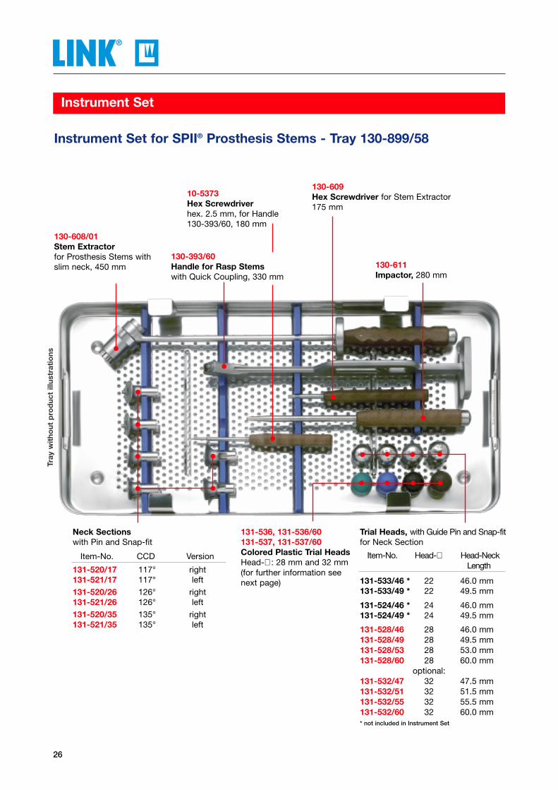
Instrument Set for SPII® Prosthesis Stems - Tray 130-899/58
130-608/01Stem Extractorfor Prosthesis Stems withslim neck, 450 mm
130-609Hex Screwdriver for Stem Extractor175 mm
130-611Impactor, 280 mm
130-393/60Handle for Rasp Stemswith Quick Coupling, 330 mm
131-536, 131-536/60131-537, 131-537/60 Colored Plastic Trial HeadsHead-∅ : 28 mm and 32 mm(for further information seenext page)
Neck Sections with Pin and Snap-fit
Item-No. CCD Version
131-520/17 117° right131-521/17 117° left131-520/26 126° right131-521/26 126° left131-520/35 135° right131-521/35 135° left
Trial Heads, with Guide Pin and Snap-fitfor Neck Section
Item-No. Head-∅ Head-Neck Length
131-533/46 * 22 46.0 mm131-533/49 * 22 49.5 mm
131-524/46 * 24 46.0 mm131-524/49 * 24 49.5 mm
131-528/46 28 46.0 mm131-528/49 28 49.5 mm131-528/53 28 53.0 mm131-528/60 28 60.0 mm
optional:131-532/47 32 47.5 mm131-532/51 32 51.5 mm131-532/55 32 55.5 mm131-532/60 32 60.0 mm* not included in Instrument Set
10-5373Hex Screwdriverhex. 2.5 mm, for Handle 130-393/60, 180 mm
Tray
wit
hout
pro
duc
t ill
ustr
atio
ns
27
Instrument Set
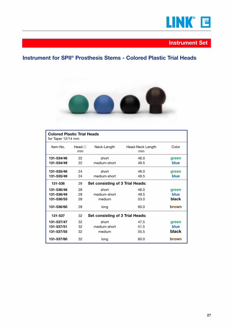
Colored Plastic Trial Headsfor Taper 12/14 mm
Item-No. Head-∅ Neck-Length Head-Neck Length Colormm mm
131-534/46 22 short 46.0 green131-534/49 22 medium-short 49.5 blue
131-535/46 24 short 46.0 green131-535/49 24 medium-short 49.5 blue
131-536 28 Set consisting of 3 Trial Heads:
131-536/46 28 short 46.0 green131-536/49 28 medium-short 49.5 blue131-536/53 28 medium 53.0 black
131-536/60 28 long 60.0 brown
131-537 32 Set consisting of 3 Trial Heads:
131-537/47 32 short 47.5 green131-537/51 32 medium-short 51.5 blue131-537/55 32 medium 55.5 black
131-537/60 32 long 60.0 brown
Instrument for SPII® Prosthesis Stems - Colored Plastic Trial Heads
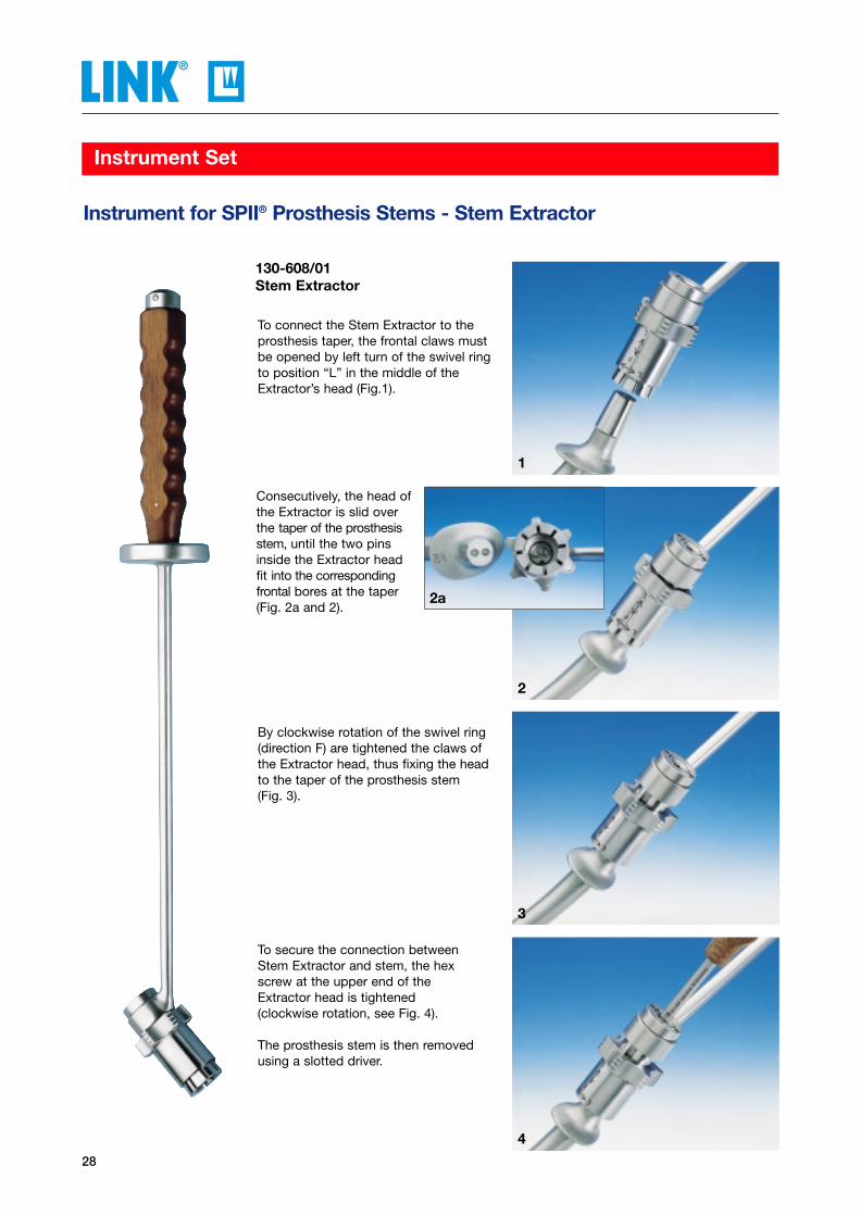
Consecutively, the head ofthe Extractor is slid overthe taper of the prosthesisstem, until the two pinsinside the Extractor headfit into the correspondingfrontal bores at the taper(Fig. 2a and 2).
28
Instrument Set
By clockwise rotation of the swivel ring(direction F) are tightened the claws ofthe Extractor head, thus fixing the headto the taper of the prosthesis stem (Fig. 3).
To secure the connection betweenStem Extractor and stem, the hexscrew at the upper end of theExtractor head is tightened (clockwise rotation, see Fig. 4).
The prosthesis stem is then removedusing a slotted driver.
Instrument for SPII® Prosthesis Stems - Stem Extractor
130-608/01Stem Extractor
To connect the Stem Extractor to theprosthesis taper, the frontal claws mustbe opened by left turn of the swivel ringto position “L” in the middle of theExtractor’s head (Fig.1).
1
2a
2
3
4

29
Instrument Set
Instrument for SPII® Prosthesis Stems - Handle for Rasp Stems
130-393/60Handle for Rasp Stemswith Quick Coupling, with impact plate to impact andeasily extract the Rasp Stem330 mm
1
2
3
2a
To connect Rasp Stem and Handle, thetrigger is retracted until its stop (arrow).Then, the Rasp Stem trunnion is intro-duced into the frontal reception of theHandle (Fig.1).
To secure the coupling between RaspStem and Handle, the trigger is pusheddown (arrow) (Fig. 2).
Rasp Stem with coupled Handle (Fig. 2a).
The trigger is pulled back until its stopto separate the coupling (arrow) (Fig. 3).Now the Handle can be detached fromthe Rasp Stem.
30
Instrument Set
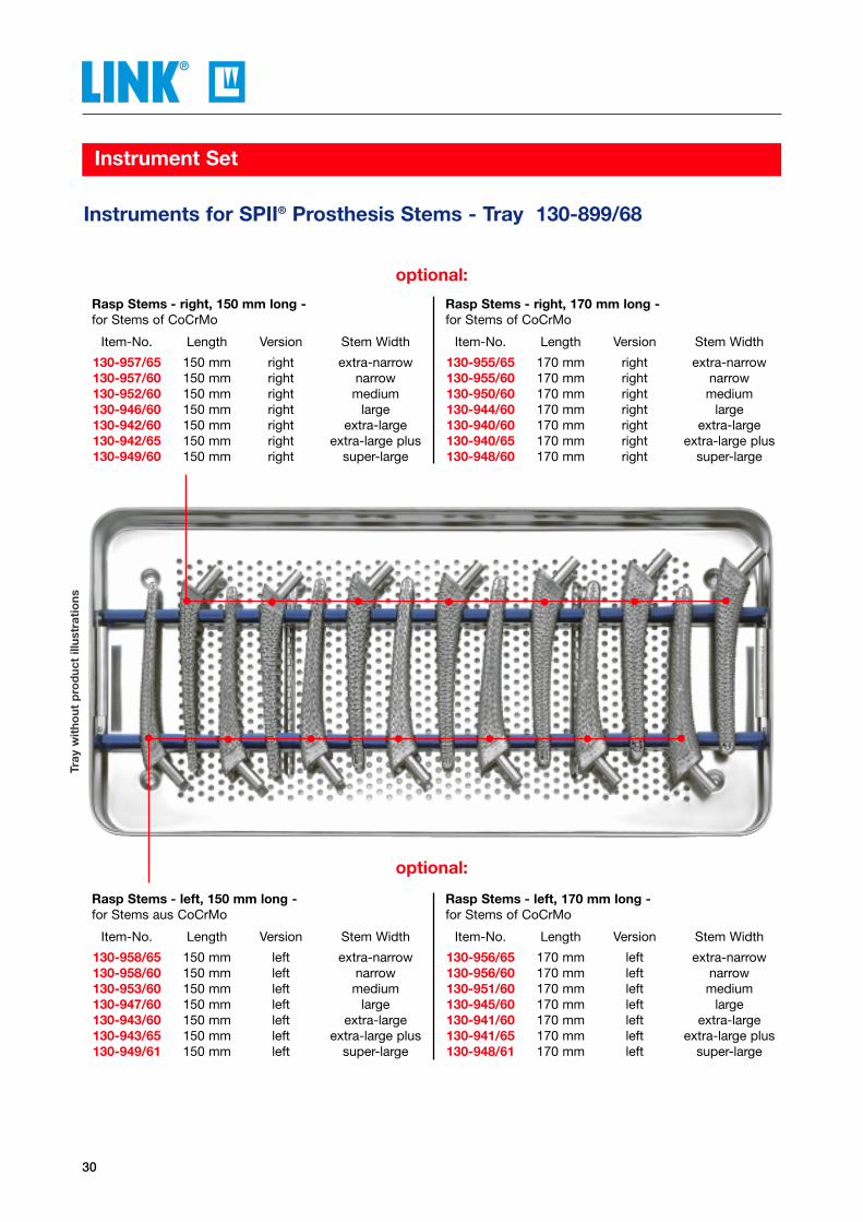
Instruments for SPII® Prosthesis Stems - Tray 130-899/68
Rasp Stems - left, 150 mm long - for Stems aus CoCrMo
Item-No. Length Version Stem Width
130-958/65 150 mm left extra-narrow130-958/60 150 mm left narrow130-953/60 150 mm left medium130-947/60 150 mm left large130-943/60 150 mm left extra-large130-943/65 150 mm left extra-large plus130-949/61 150 mm left super-large
Rasp Stems - left, 170 mm long - for Stems of CoCrMo
Item-No. Length Version Stem Width
130-956/65 170 mm left extra-narrow130-956/60 170 mm left narrow130-951/60 170 mm left medium130-945/60 170 mm left large130-941/60 170 mm left extra-large130-941/65 170 mm left extra-large plus130-948/61 170 mm left super-large
optional:
Rasp Stems - right, 150 mm long - for Stems of CoCrMo
Item-No. Length Version Stem Width
130-957/65 150 mm right extra-narrow130-957/60 150 mm right narrow130-952/60 150 mm right medium130-946/60 150 mm right large130-942/60 150 mm right extra-large130-942/65 150 mm right extra-large plus130-949/60 150 mm right super-large
Rasp Stems - right, 170 mm long - for Stems of CoCrMo
Item-No. Length Version Stem Width
130-955/65 170 mm right extra-narrow130-955/60 170 mm right narrow130-950/60 170 mm right medium130-944/60 170 mm right large130-940/60 170 mm right extra-large130-940/65 170 mm right extra-large plus130-948/60 170 mm right super-large
optional:
Tray
wit
hout
pro
duc
t ill
ustr
atio
ns
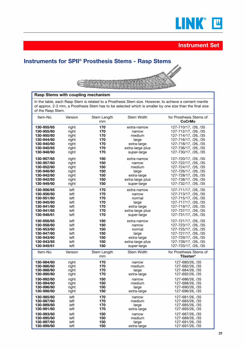
Rasp Stems with coupling mechanism
In the table, each Rasp Stem is related to a Prosthesis Stem size. However, to achieve a cement mantleof approx. 2-3 mm, a Prosthesis Stem has to be selected which is smaller by one size than the final sizeof the Rasp Stem.
Item-No. Version Stem Length Stem Width for Prosthesis Stems ofmm CoCrMo
130-955/65 right 170 extra-narrow 127-710/17, /26, /35130-955/60 right 170 narrow 127-712/17, /26, /35130-950/60 right 170 medium 127-714/17, /26, /35130-944/60 right 170 large 127-716/17, /26, /35130-940/60 right 170 extra-large 127-718/17, /26, /35130-940/65 right 170 extra-large plus 127-736/17, /26, /35130-948/60 right 170 super-large 127-730/17, /26, /35
130-957/65 right 150 extra-narrow 127-720/17, /26, /35130-957/60 right 150 narrow 127-722/17, /26, /35130-952/60 right 150 medium 127-724/17, /26, /35130-946/60 right 150 large 127-726/17, /26, /35130-942/60 right 150 extra-large 127-728/17, /26, /35130-942/65 right 150 extra-large plus 127-738/17, /26, /35130-949/60 right 150 super-large 127-732/17, /26, /35
130-956/65 left 170 extra-narrow 127-711/17, /26, /35130-956/60 left 170 narrow 127-713/17, /26, /35130-951/60 left 170 normal 127-715/17, /26, /35130-945/60 left 170 large 127-717/17, /26, /35130-941/60 left 170 extra-large 127-719/17, /26, /35130-941/65 left 170 extra-large plus 127-737/17, /26, /35130-948/61 left 170 super-large 127-731/17, /26, /35
130-958/65 left 150 extra-narrow 127-721/17, /26, /35130-958/60 left 150 narrow 127-723/17, /26, /35130-953/60 left 150 normal 127-725/17, /26, /35130-947/60 left 150 large 127-727/17, /26, /35130-943/60 left 150 extra-large 127-729/17, /26, /35130-943/65 left 150 extra-large plus 127-739/17, /26, /35130-949/61 left 150 super-large 127-733/17, /26, /35
Item-No. Version Stem Length Stem Width for Prosthesis Stems ofmm Tilastan®
130-984/60 right 170 narrow 127-680/26, /35130-986/60 right 170 medium 127-682/26, /35130-988/60 right 170 large 127-684/26, /35130-990/60 right 170 extra-large 127-692/26, /35130-992/60 right 150 narrow 127-686/26, /35130-994/60 right 150 medium 127-688/26, /35130-996/60 right 150 large 127-690/26, /35130-998/60 right 150 extra-large 127-696/26, /35
130-985/60 left 170 narrow 127-681/26, /35130-987/60 left 170 medium 127-683/26, /35130-989/60 left 170 large 127-685/26, /35130-991/60 left 170 extra-large 127-693/26, /35130-993/60 left 150 narrow 127-687/26, /35130-995/60 left 150 medium 127-689/26, /35130-997/60 left 150 large 127-691/26, /35130-999/60 left 150 extra-large 127-697/26, /35
31
Instrument Set
Instruments for SPII® Prosthesis Stems - Rasp Stems
32
Instrument Set
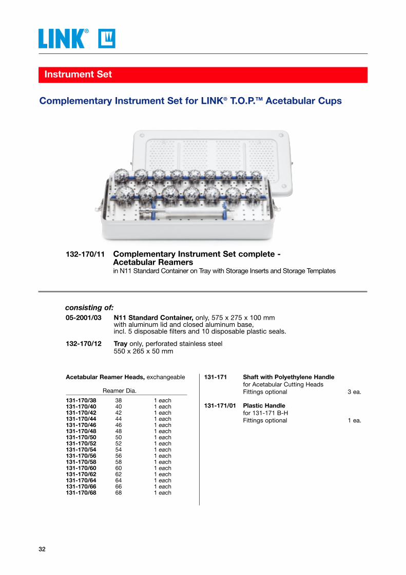
Complementary Instrument Set for LINK® T.O.P.TM Acetabular Cups
132-170/11 Complementary Instrument Set complete - Acetabular Reamersin N11 Standard Container on Tray with Storage Inserts and Storage Templates
05-2001/03 N11 Standard Container, only, 575 x 275 x 100 mmwith aluminum lid and closed aluminum base, incl. 5 disposable filters and 10 disposable plastic seals.
132-170/12 Tray only, perforated stainless steel550 x 265 x 50 mm
consisting of:
131-171 Shaft with Polyethylene Handlefor Acetabular Cutting HeadsFittings optional 3 ea.
131-171/01 Plastic Handlefor 131-171 B-HFittings optional 1 ea.
Acetabular Reamer Heads, exchangeable
Reamer Dia.
131-170/38 38 1 each131-170/40 40 1 each131-170/42 42 1 each131-170/44 44 1 each131-170/46 46 1 each131-170/48 48 1 each131-170/50 50 1 each131-170/52 52 1 each131-170/54 54 1 each131-170/56 56 1 each131-170/58 58 1 each131-170/60 60 1 each131-170/62 62 1 each131-170/64 64 1 each131-170/66 66 1 each131-170/68 68 1 each
33
Instrument Set
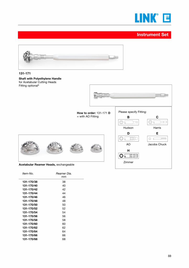
Acetabular Reamer Heads, exchangeable
Item-No. Reamer Dia.mm
131-170/38 38131-170/40 40131-170/42 42131-170/44 44131-170/46 46131-170/48 48131-170/50 50131-170/52 52131-170/54 54131-170/56 56131-170/58 58131-170/60 60131-170/62 62131-170/64 64131-170/66 66131-170/68 68
How to order: 131-171 D= with AO Fitting
131-171
Shaft with Polyethylene Handlefor Acetabular Cutting HeadsFitting optional*
1/3
Please specify Fitting:
B C
Hudson Harris
D E
AO Jacobs Chuck
H
Zimmer
34
Additional Instruments
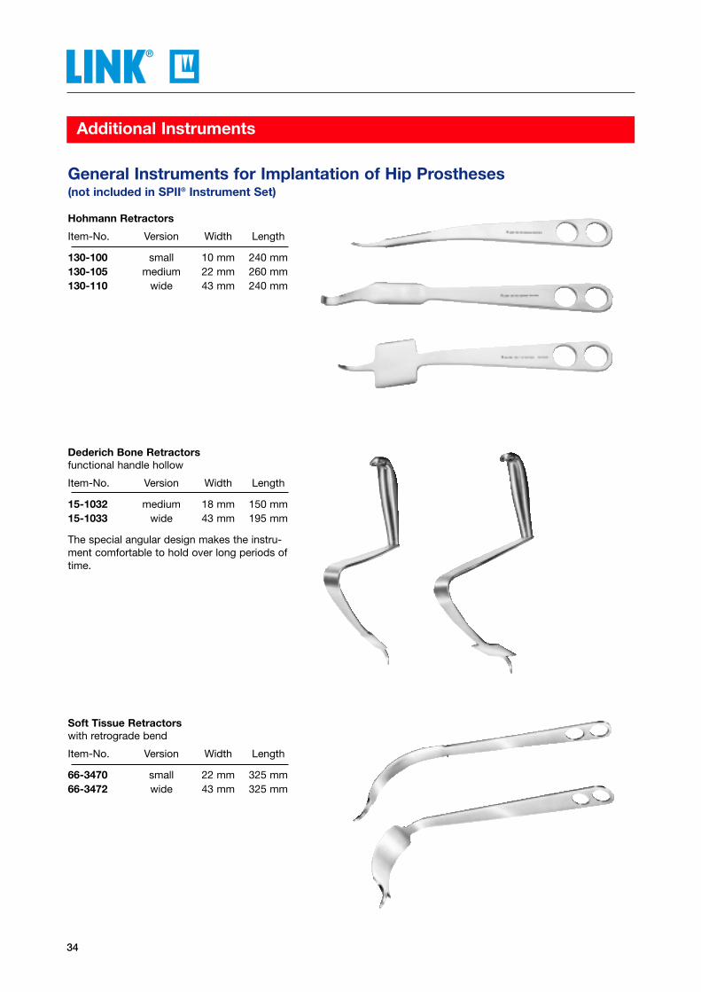
Hohmann Retractors
Item-No. Version Width Length
130-100 small 10 mm 240 mm130-105 medium 22 mm 260 mm130-110 wide 43 mm 240 mm
Dederich Bone Retractorsfunctional handle hollow
Item-No. Version Width Length
15-1032 medium 18 mm 150 mm15-1033 wide 43 mm 195 mm
The special angular design makes the instru-ment comfortable to hold over long periods oftime.
Soft Tissue Retractorswith retrograde bend
Item-No. Version Width Length
66-3470 small 22 mm 325 mm66-3472 wide 43 mm 325 mm
General Instruments for Implantation of Hip Prostheses(not included in SPII® Instrument Set)
35
Additional Instruments
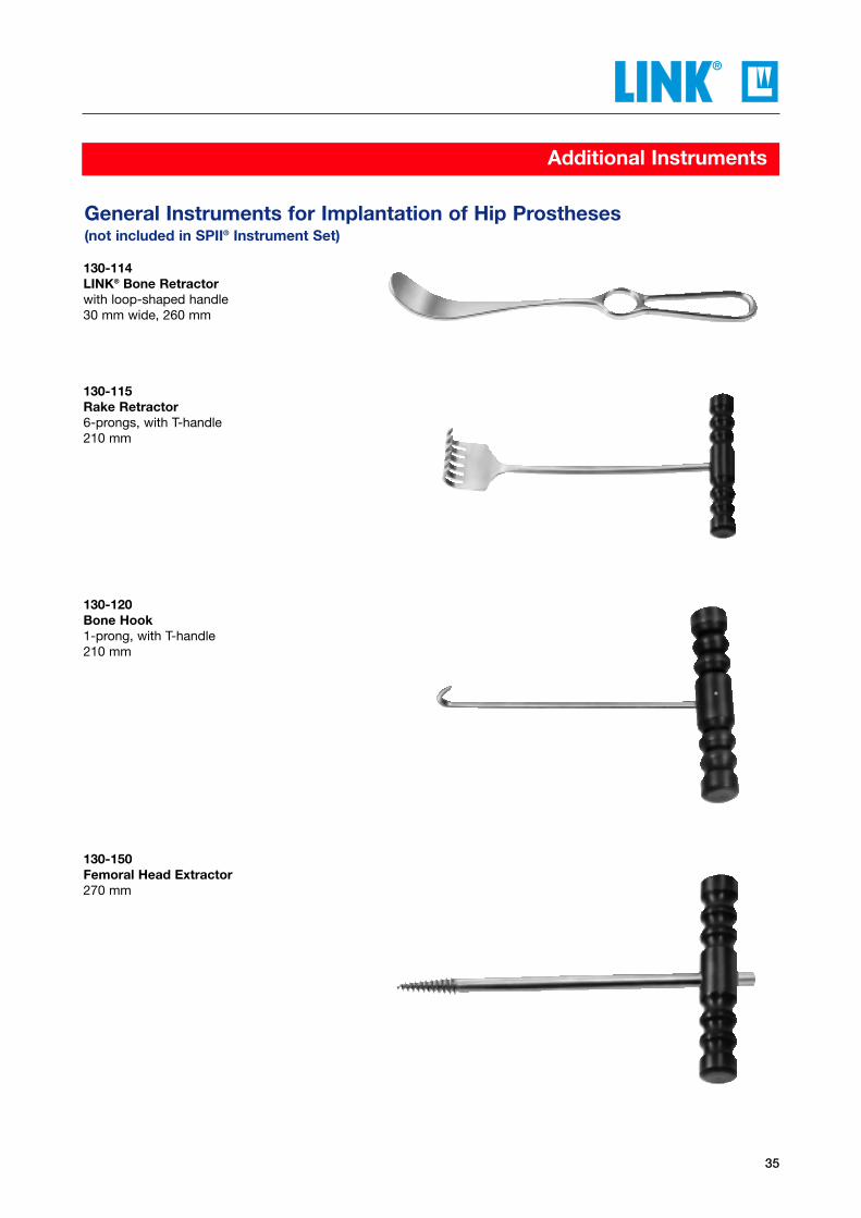
130-114LINK® Bone Retractorwith loop-shaped handle30 mm wide, 260 mm
130-115Rake Retractor6-prongs, with T-handle210 mm
130-120Bone Hook1-prong, with T-handle210 mm
130-150Femoral Head Extractor270 mm
General Instruments for Implantation of Hip Prostheses(not included in SPII® Instrument Set)
36
Additional Instruments
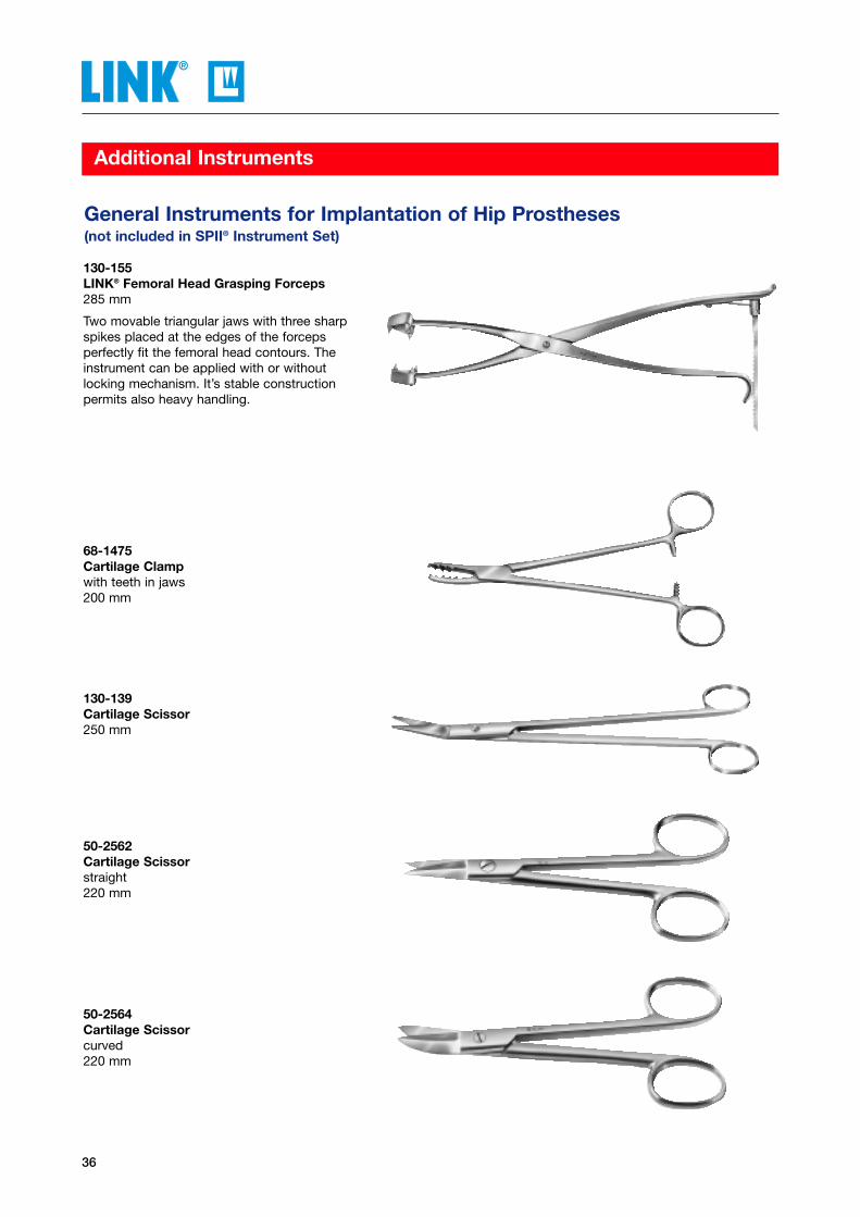
130-155LINK® Femoral Head Grasping Forceps285 mm
Two movable triangular jaws with three sharpspikes placed at the edges of the forceps perfectly fit the femoral head contours. Theinstrument can be applied with or without locking mechanism. It’s stable construction permits also heavy handling.
68-1475Cartilage Clampwith teeth in jaws200 mm
130-139Cartilage Scissor250 mm
50-2562Cartilage Scissorstraight220 mm
50-2564Cartilage Scissorcurved220 mm
General Instruments for Implantation of Hip Prostheses(not included in SPII® Instrument Set)
37
Additional Instruments
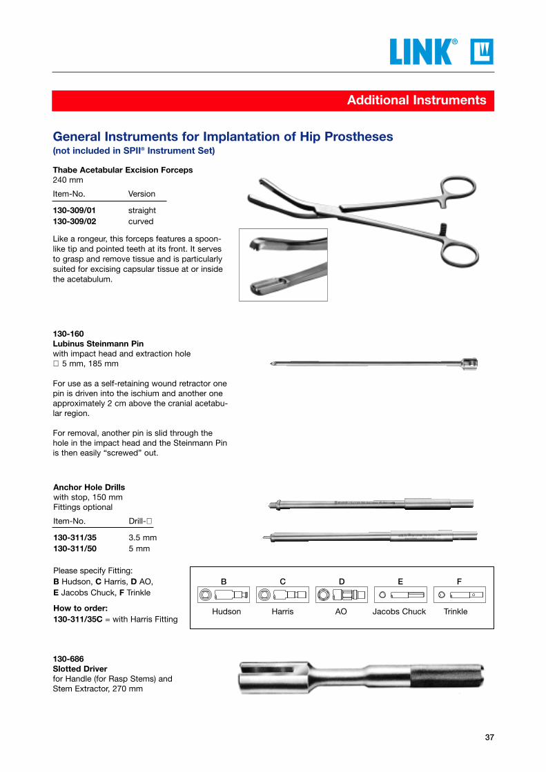
130-160Lubinus Steinmann Pinwith impact head and extraction hole∅ 5 mm, 185 mm
For use as a self-retaining wound retractor onepin is driven into the ischium and another oneapproximately 2 cm above the cranial acetabu-lar region.
For removal, another pin is slid through thehole in the impact head and the Steinmann Pinis then easily “screwed” out.
Anchor Hole Drillswith stop, 150 mmFittings optional
Item-No. Drill-∅
130-311/35 3.5 mm130-311/50 5 mm
Please specify Fitting:B Hudson, C Harris, D AO, E Jacobs Chuck, F Trinkle
How to order:130-311/35C = with Harris Fitting
Thabe Acetabular Excision Forceps240 mm
Item-No. Version
130-309/01 straight130-309/02 curved
Like a rongeur, this forceps features a spoon-like tip and pointed teeth at its front. It servesto grasp and remove tissue and is particularlysuited for excising capsular tissue at or insidethe acetabulum.
130-686Slotted Driverfor Handle (for Rasp Stems) and Stem Extractor, 270 mm
Hudson Harris AO Jacobs Chuck Trinkle
FEDCB
General Instruments for Implantation of Hip Prostheses(not included in SPII® Instrument Set)

38
Additional Instruments
130-610Cement Packer∅ 10 mm, 300 mm
Bone Plug Impactorsto insert bone plugs into the medullarycavity, 400 mm
Item-No. ∅
Unthreaded131-200 08 mm131-202 10 mm131-204 12 mm131-206 14 mm131-208 16 mm131-210 18 mm
Threaded131-220 08 mm131-222 10 mm131-224 12 mm131-226 14 mm131-228 16 mm131-230 18 mm
Acetabular Cup Pusher with T-Handle260 mm
Item-No. for Acetabular Cups
130-350 Inner-∅ 32 mm130-351 Inner-∅ 28 mm
Replacement Heads130-350/02 for 130-350130-351/02 for 130-351
130-350/05T-Handle onlyfor Cup Pushers 130-350 and 130-351
General Instruments for Implantation of Hip Prostheses(not included in SPII® Instrument Set)
39
Accessories
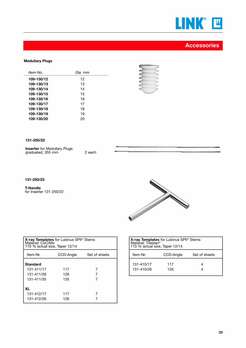
Medullary Plugs
Item-No. Dia. mm
109-130/12 12109-130/13 13109-130/14 14109-130/15 15109-130/16 16109-130/17 17109-130/18 18109-130/19 19109-130/20 20
131-250/22
Inserter for Medullary Plugsgraduated, 355 mm 2 each
131-250/23
T-Handlefor Inserter 131-250/22
X-ray Templates for Lubinus SPII® StemsMaterial: CoCrMo110 % actual size, Taper 12/14
Item-Nr. CCD-Angle Set of sheets
Standard131-411/17 117 7131-411/26 126 7131-411/35 135 7
XL131-412/17 117 7131-412/26 126 7
X-ray Templates for Lubinus SPII® StemsMaterial: Tilastan®
110 % actual size, Taper 12/14
Item-Nr. CCD-Angle Set of sheets
131-410/17 117 4131-410/26 126 4
40
Information
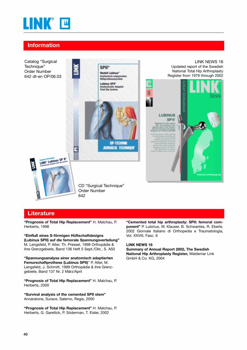
Catalog “SurgicalTechnique”Order Number642 dt-en OP/06.03
LINK NEWS 16Updated report of the SwedishNational Total Hip Arthroplasty
Register from 1979 through 2002
Literature
CD “Surgical Technique”Order Number642
“Prognosis of Total Hip Replacement” H. Malchau, P.Herberts, 1998
“Einfluß eines S-förmigen Hüftschaftdesigns (Lubinus SPII) auf die femorale Spannungsverteilung”M. Lengsfeld, P. Alter, Th. Pressel, 1998 Orthopädie &ihre Grenzgebiete, Band 136 Heft 5 Sept./Okt., S. A50
“Spannungsanalyse einer anatomisch adaptiertenFemurschaftprothese (Lubinus SPII)” P. Alter, M.Lengsfeld, J. Schmitt, 1999 Orthopädie & ihre Grenz-gebiete, Band 137 Nr. 2 März/April
“Prognosis of Total Hip Replacement” H. Malchau, P.Herberts, 2000
“Survival analysis of the cemented SPII stem”Annaratone, Surace, Salerno, Regis, 2000
“Prognosis of Total Hip Replacement” H. Malchau, P.Herberts, G. Garellick, P. Söderman, T. Eisler, 2002
“Cemented total hip arthroplasty: SPII: femoral com-ponent” P. Lubinus, W. Klauser, B. Schwantes, R. Eberle,2002 Giornale Italiano di Orthopedia e Traumatologia, Vol. XXVIII, Fasc. 6
LINK NEWS 16Summary of Annual Report 2002, The SwedishNational Hip Arthroplasty Register, Waldemar LinkGmbH & Co. KG, 2004
Surgical Technique
LINK® Lubinus SP II®
Anatomically Adapted Total Hip System®

41
Alphabetical Index
AAAA
Accessoires ................................................................. 39
Acetabular Cups .................................................... 14-21
Acetabular Cup Pusher with T-Handle ....................... 38
Acetabular Cutting Heads, exchangeable ................. 33
Acetabular Excision Forceps .................................... 37
Acetabluar Screw-in Cups, Type K ..................... 18, 19
Acetabular Screw-in Cups, Type V ..................... 20, 21
Additional Instruments .......................................... 34-38
Anchor Hole Drills ...................................................... 37
BBBB
Bone Hook ................................................................... 35
Bone Plug Impactors ................................................. 38
Bone Retractors ......................................................... 35
CCCC
Calcar Reamers ........................................................... 25
Cartilage Clamp .......................................................... 36
Cartilage Scissors ....................................................... 36
Cement Packer ............................................................ 38
Colored Plastic Trial Heads .................................. 26, 27
Complementary Instrument Setcomplete, T.O.P.TM Acetabular Cups ............................ 32
DDDD
Dederich Bone Retractors .......................................... 34
Description ................................................................. 2-3
Driver for Prosthesis Heads ...................................... 25
FFFF
Femoral Head Extractor.............................................. 35
Femoral Head Grasping Forceps ............................... 36
Femoral Reamers, flexible .......................................... 25
Fittings ......................................................................... 25
Fixation Screws .......................................................... 16
GGGG
General Instruments, for implantation Hip Prostheses. .............................34–38
HHHH
Handle for Calcar Reamer ........................................... 25
Handle for Rasp Stems ......................................... 26, 29
Head Remover ............................................................ 25
Hex Screwdrivers ....................................................... 26
Hohmann Retractors ................................................... 34
IIII
Impactors .............................................................. 25, 26
Implants ................................................................... 4–22
Information .................................................................. 40
Insert for Medullary Plugs ........................................... 39
Inserting Forceps ........................................................ 25
Instrument Set,complete for SPII® Prosthesis Stems ...................... 23-24
IP Acetabular Cups ................................................... 15
LLLL
Literature ..................................................................... 40
Long Prosthesis Stems ................................................ 8
Lubinus Eccentric Acetabular Cups .......................... 14
Lubinus Steinmann Pin ............................................... 37
MMMM
Medullary Plugs .......................................................... 39
Metal Casings for Acetabular Screw-in Cups Type K ..18
Metal Casings for Acetabular Screw-in Cups Type V ..20
Metal Casings for T.O.P.™ Acetabular Cup System ... 16
NNNN
Neck Sections ............................................................. 26
....................................................................................Page....................................................................................Page
42
Alphabetical Index
....................................................................................Page
PPPP
Polyethylene Inserts for LINK® Acetabular Screw-inCups Type K ................................................................. 19
Polyethylene Inserts for LINK® Acetabular Screw-inCups Type V ................................................................. 21
Polyethylene Inserts, standard ................................... 17
Prosthesis Heads ................................................. 12, 13
Prosthesis Stems .................................................... 4-11
RRRR
Rake Retractor ........................................................... 35
Rasp Stems ........................................................... 30, 31
Replacement Heads .................................................... 38
Replacement Peep-Hole Screws .............................. 16
Retractors ................................................................... 34
SSSS
Scissors ........................................................................ 34
Shaft with Polyethylene Handle ................................ 33
Slotted Driver ............................................................... 37
Soft Tissue Retractors ................................................ 34
SPII® Long Prosthesis Stems .................................. 8, 9
SPII® Prosthesis Stems of CoCrMo ........................ 4, 5
SPII® Prosthesis Stems of Tilastan® .................... 10, 11
SPII® Prosthesis Stems XL, with long Neck ............ 6, 7
Standard Container N11 ...................................... 23, 24
Standard Container N31 ............................................ 25
Stem Extractor....................................................... 26, 28
TTTT
T-Handle for Cup Pusher .............................................. 38
T-Handle for Insert ........................................................ 39
Thabe Acetabular Excision Forceps.......................... 37
T.O.P.™ Acetabular Cup System, cementless ... 16, 17
T.O.P.™ Polyethylene Inserts...................................... 17
Trays .................................................................25, 26, 30
Trial Heads ............................................................ 26, 27
VVVV
Vario-Cup Prosthesis ................................................. 22
XXXX
X-ray Templates .......................................................... 39
....................................................................................Page

43
Numerical Index
130-100 to 130-110 ..................................................... 34
130-114, 130-115 ......................................................... 35
130-120 ........................................................................ 35
130-139 ........................................................................ 36
130-150 ........................................................................ 35
130-155 ....................................................................... 36
130-160 ........................................................................ 37
130-309/01, 130-309/02 .............................................. 37
130-311/35, 130-311/50 .............................................. 37
130-350, 130-351 ......................................................... 38
130-350/02, 130-351/02 .............................................. 38
130-350/05 ................................................................... 38
130-360 to 130-368 ............................................... 24, 25
130-393/60 ....................................................... 24, 26, 29
130-406/01 ............................................................. 23, 25
130-408 .................................................................. 23, 25
130-600 .................................................................. 23, 25
130-608/01 ....................................................... 24, 26, 28
130-609 .................................................................. 24, 26
130-610 ........................................................................ 38
130-611 .................................................................. 24, 26
130-686 ........................................................................ 37
130-899/58, 130-899/59 .............................................. 23
130-899/68 ................................................................... 24
130-899/70 to 130-899/81 .......................................... 23
130-899/72, 130-899/82 .............................................. 23
130-899/83, 130-899/84 .............................................. 24
130-940/60 to 130-958/60 .............................. 24, 30, 31
130-940/65 to 130-958/65 ............................... 24, 30, 31
130-948/61 ....................................................... 24, 30, 31
130-949/61 ....................................................... 24, 30, 31
130-959 .................................................................. 23, 25
130-984/60 to 130-999/60 .......................................... 31
131-170/11, 131-170/12 ............................................... 32
131-170/38 to 131-170/68 ..................................... 32, 33
131-171 ................................................................... 32, 33
131-171/01 .................................................................... 32
131-200 to 131-210 ..................................................... 38
....................................................................................Page....................................................................................Page
05-2001/03 ............................................................. 24, 32
05-2003/03 ............................................................. 23, 25
10-5373 .................................................................. 24, 26
15-1032, 15-1033 ......................................................... 34
50-2562, 50-2564 ......................................................... 36
66-3470, 66-3472 ......................................................... 34
68-1475 ........................................................................ 36
101-102 to 101-136 ..................................................... 14
102-102 to 102-136 ..................................................... 14
105-200 to 105-335 ..................................................... 15
107-210/39 to 107-210/43 .......................................... 22
107-220/44 to 107-220/65 .......................................... 22
107-230/49 to 107-230/65 .......................................... 22
109-130/12 to 109-130/20............................................ 39
126-838 to 126-854 ..................................................... 13
127-680/26 to 127-697/26 .......................................... 11
127-680/35 to 127-697/35 .......................................... 11
127-710/17 to 127-739/17 ............................................ 5
127-710/26 to 127-739/26 ............................................ 5
127-710/35 to 127-739/35 ............................................ 5
127-740/17 to 127-773/17 ............................................ 7
127-740/26 to 127-773/26 ............................................ 7
127-910/26 to 127-933/26 ............................................ 9
127-910/35 to 127-933/35 ............................................ 9
128-743/46, 128-743/49 ............................................... 12
128-744 to 128-787 ...................................................... 12
128-760 to 128-770 ...................................................... 12

44
Numerical Index
131-220 to 131-230 ..................................................... 38
131-250/22, 131-250/23 ............................................... 39
131-410/17, 131-410/26 ............................................... 39
131-411/17 to 131-411/35............................................ 39
131-412/17, 131-412/26 ............................................... 39
131-520/17, 131-521/17 ........................................ 24, 26
131-520/26. 131-521/26 ........................................ 24, 26
131-520/35, 131-521/35 ......................................... 24, 26
131-524/46, 131-524/49 .............................................. 26
131-528/46 to 131-528/60 .................................... 24, 26
131-532/47 to 131-532/60 .................................... 24, 26
131-533/46, 131-533/49 .............................................. 26
131-534/46, 131-534/49 .............................................. 27
131-535/46, 131-535/49 .............................................. 27
131-536, 131-536/60 ........................................ 24, 26, 27
131-536/46 to 131-536/53 .......................................... 27
131-537, 131-537/60 ....................................... 24, 26, 27
131-537/47 to 131-537/55 .......................................... 27
131-597 .................................................................. 23, 25
131-830/01 ............................................................. 23, 25
132-170/11, 132-170/12 .............................................. 32
175-606/01 ................................................................... 25
180-048/00 to 180-060/00 .......................................... 19
180-048/05 to 180-060/05 .......................................... 19
180-048/10 to 180-060/10 .......................................... 19
180-148/00 to 180-160/00 .......................................... 19
180-148/05 to 180-160/05 .......................................... 19
180-148/10 to 180-160/10 .......................................... 19
180-248/11 to 180-268/11 .......................................... 18
180-248/12 to 180-268/12 .......................................... 18
180-540/01 to 180-568/01 .......................................... 20
180-540/02 to 180-568/02 .......................................... 20
180-656/15 to 180-656/30 .......................................... 16
180-669/01 to 180-719/01 .......................................... 21
180-669/02 to 180-719/02 .......................................... 21
180-719/05, 180-719/06 .............................................. 21
180-721/11 to 180-746/11 .......................................... 21
180-721/12 to 180-746/12 .......................................... 21
180-750/40, 180-750/42 ............................................... 17
180-751/44 to 180-751/68............................................ 17
290-300/40 to 290-300/68 .......................................... 16
290-305 ........................................................................ 16
290-320/40, 290-320/42 .............................................. 17
290-321/44 to 290-321/68 .......................................... 17
....................................................................................Page....................................................................................Page

Important Information about our Orthopaedic Implants
WALDEMAR LINK GmbH & Co. KG, Hamburg
This catalog was developed for the sale and promotion of our products described and illustrated herein. Reproduction of its contents,or any part thereof, is expressly prohibited. In the event of misuse, we reserve the right to reclaim both catalog and price list as wellas the right to recourse.
All instruments, unless otherwise noted, are made of stainless steel.
The Implants are supplied in sterile packaging.
Detailed information on important criteria can be supplied uponrequest.
Implants for osteosynthesis are intended to support andguide fractures during the normal healing process, whileendoprostheses are intended for replacement of normalbody structures. When using implants, the surgeonshould be aware of the following:
1. Selecting the correct implant is extremely important. The potential for successful surgery is greatlyincreased by selecting the proper type and size ofimplant. Size and shape of the human bone placerestrictions on the size and shape of the implant, thus limiting its weight-bearing capabilities. No implant can be expected to withstand theunsupported stress of full body weight. Endoprostheses are especially dependent upon proper placement and adequate bone support andshould not be expected to withstand more than thenormal stresses and functional body weight.
2. Correct handling of the implant is extremelyimportant. Contouring of implants impairs the service life of the implant. If contouring is necessary for surgical reasons, the following manipulations must not beundertaken: sharp bends, reverse bending, scratchingor notching. Any of these and similar manipulationscan produce defects in surface finish causing internalstress concentrations which may weaken the implantand lead to eventual failure.
3. No surgical implant should ever be re-used. Even if a previously used implant appears undamaged, it may already have developed internalfatigue which can lead to failure. We urge you to useonly new implants of the latest design and construction.
4. Post-operative care is important. The patient must be made aware of the limitations ofhis new implant. He must be cautioned that the newimplant can be expected to withstand only limitedstress until the supporting bones are completely healed. The load-bearing capability of implants cannot be compared to that of a healthy bone.

©W
.LIN
K 6
42en
Imp
l./In
str.
/12.
04 B
&G
WALDEMAR LINK GmbH & Co. KG
Barkhausenweg 10 · D-22339 Hamburg
P. O. Box 63 05 52 · D-22315 Hamburg
Phone +49 (0)40 5 39 95-0
Fax +49 (0)40 5 38 69 29
e-mail [email protected]
Internet www.linkhh.de