Embed Size (px)
Citation preview

MEF 8 © The Metro Ethernet Forum 2004. Any reproduction of this document, or any portion thereof, shall contain the following statement: "Reproduced with permission of the Metro Ethernet Forum." No user of this document is authorized to modify any of the information contained herein.
MEF 8
Implementation Agreement for the Emulation of PDH Circuits over Metro Ethernet Networks
October 2004
Implementation Agreement for the Emulation of
PDH Circuits over Metro Ethernet Networks
MEF 8 © The Metro Ethernet Forum 2004. Any reproduction of this document, or any portion thereof, shall contain the following statement: "Reproduced with permission of the Metro Ethernet Forum." No user of this document is authorized to modify any of the information contained herein.
Page i
Disclaimer
The information in this publication is freely available for reproduction and use by any recipient and is believed to be accurate as of its publication date. Such information is subject to change without notice and the Metro Ethernet Forum (MEF) is not responsible for any errors. The MEF does not assume responsibility to update or correct any information in this publication. No representation or warranty, expressed or implied, is made by the MEF concerning the completeness, accuracy, or applicability of any information contained herein and no liability of any kind shall be assumed by the MEF as a result of reliance upon such information.
The information contained herein is intended to be used without modification by the recipient or user of this document. The MEF is not responsible or liable for any modifications to this document made by any other party.
The receipt or any use of this document or its contents does not in any way create, by implication or otherwise:
(a) any express or implied license or right to or under any patent, copyright, trademark or trade secret rights held or claimed by any MEF member company which are or may be associated with the ideas, techniques, concepts or expressions contained herein; nor
(b) any warranty or representation that any MEF member companies will announce any product(s) and/or service(s) related thereto, or if such announcements are made, that such announced product(s) and/or service(s) embody any or all of the ideas, technologies, or concepts contained herein; nor
(c) any form of relationship between any MEF member companies and the recipient or user of this document. Implementation or use of specific Metro Ethernet standards or recommendations and MEF specifications will be voluntary, and no company shall be obliged to implement them by virtue of participation in the Metro Ethernet Forum. The MEF is a non-profit international organization accelerating industry cooperation on Metro Ethernet technology. The MEF does not, expressly or otherwise, endorse or promote any specific products or services.
© The Metro Ethernet Forum 2004. All Rights Reserved.

Implementation Agreement for the Emulation of
PDH Circuits over Metro Ethernet Networks
MEF 8 © The Metro Ethernet Forum 2004. Any reproduction of this document, or any portion thereof, shall contain the following statement: "Reproduced with permission of the Metro Ethernet Forum." No user of this document is authorized to modify any of the information contained herein.
Page ii
Table of Contents 1. ABSTRACT .......................................................................................................................................................... 1 2. TERMINOLOGY .................................................................................................................................................. 1 3. SCOPE ................................................................................................................................................................... 3 4. COMPLIANCE LEVELS ..................................................................................................................................... 3 5. SERVICE DESCRIPTION .................................................................................................................................... 3 6. INTERWORKING FUNCTION ........................................................................................................................... 3
6.1 ARCHITECTURE .............................................................................................................................................. 3 6.1.1 Functional Layering .............................................................................................................................. 3 6.1.2 Direction terminology ............................................................................................................................ 4 6.1.3 Functional Components and Interfaces ................................................................................................. 4 6.1.4 TDM Service Processor (TSP) ............................................................................................................... 5 6.1.5 Circuit Emulation Inter-working Function (CES IWF) ......................................................................... 6 6.1.6 Emulated Circuit De/Multiplexing Function (ECDX) ........................................................................... 6 6.1.7 Ethernet Flow Termination Function (EFTF) ....................................................................................... 6
6.2 ENCAPSULATION ............................................................................................................................................ 7 6.2.1 Ethernet Services Layer ......................................................................................................................... 7 6.2.2 Adaptation Function Headers ................................................................................................................ 7
6.3 PAYLOAD FORMATS ...................................................................................................................................... 13 6.3.1 Structure-Agnostic Emulation .............................................................................................................. 13 6.3.2 Structure-Aware Emulation using Structure-Locked Encapsulation ................................................... 14 6.3.3 Structure-Aware Emulation using Structure-Indicated Encapsulation................................................ 15
6.4 SYNCHRONIZATION ...................................................................................................................................... 15 6.5 TDM APPLICATION SIGNALING .................................................................................................................... 17
6.5.1 CE Signaling Frames ........................................................................................................................... 17 6.5.2 Channel Associated Signaling (CAS) Frames ..................................................................................... 17 6.5.3 Common Channel Signaling (CCS) Frames ........................................................................................ 18
6.6 CESOETH DEFECTS ..................................................................................................................................... 18 6.6.1 Misconnection ...................................................................................................................................... 19 6.6.2 Reordering and Loss of Frames ........................................................................................................... 19 6.6.3 Late Arriving Frames........................................................................................................................... 20 6.6.4 Malformed CESoETH Frames ............................................................................................................. 20 6.6.5 Jitter Buffer Overrun and Underrun Defects ...................................................................................... 20
6.7 PERFORMANCE MONITORING ....................................................................................................................... 21 6.7.1 Facility Data Link ................................................................................................................................ 21 6.7.2 Errored Data ....................................................................................................................................... 21
7. SERVICE INITIATION AND OPERATION ..................................................................................................... 22

Implementation Agreement for the Emulation of
PDH Circuits over Metro Ethernet Networks
MEF 8 © The Metro Ethernet Forum 2004. Any reproduction of this document, or any portion thereof, shall contain the following statement: "Reproduced with permission of the Metro Ethernet Forum." No user of this document is authorized to modify any of the information contained herein.
Page iii
7.1 COMMON CONSIDERATIONS ......................................................................................................................... 22 7.2 CESOETH SERVICE PARAMETERS ............................................................................................................... 22 7.3 CESOETH LOCAL CONFIGURATION PARAMETERS ...................................................................................... 24
8. MEN REQUIREMENTS..................................................................................................................................... 25 8.1 MEN SERVICE TYPE ..................................................................................................................................... 25 8.2 SERVICE ATTRIBUTES ................................................................................................................................... 25
8.2.1 Bandwidth Provisioning ...................................................................................................................... 26 8.3 COS PERFORMANCE PARAMETERS ............................................................................................................... 26
8.3.1 Ethernet Frame delay .......................................................................................................................... 27 8.3.2 Ethernet Frame Delay Variation ......................................................................................................... 27 8.3.3 Ethernet Frame Loss ............................................................................................................................ 27 8.3.4 Network Availability ............................................................................................................................ 27
9. MANAGEMENT ................................................................................................................................................ 28 9.1 ALARMS ....................................................................................................................................................... 28 9.2 STATISTICS COUNTERS ................................................................................................................................. 28
10. REFERENCES .................................................................................................................................................... 29
List of Figures Figure 6-1: Functional Layering, and mapping onto encapsulation headers ................................................................ . 4 Figure 6-2: Interworking function direction ................................................................................................ .................. 4 Figure 6-3: Functional Components and Interface Types................................................................ .............................. 5 Figure 6-4: Emulated Circuit Identifier (ECID) ................................................................................................ ............ 8 Figure 6-5: Structure of the CESoETH control word ................................................................................................ .... 8 Figure 6-6: RTP Header Structure [RFC 3550] ........................................................................................................... 11
Figure 6-7: Synchronization Options for the TDM-bound IWF .................................................................................. 16
Figure 6-8: Encoding Format for CAS “ABCD” values from [RFC 2833] ................................................................. 18
Figure 8-1: Example TDM Virtual Private Line Configurations ................................................................................. 25
List of Tables Table 6-1: Meaning of the Local TDM Failure Modification bits................................................................ ................. 9 Table 6-2: Meaning of the Fragmentation bits ................................................................................................ .............. 9 Table 8-1: Example Service Attributes for an EVPL or EPL service carrying CESoETH traffic ............................... 26

Implementation Agreement for the Emulation of
PDH Circuits over Metro Ethernet Networks
MEF 8 © The Metro Ethernet Forum 2004. Any reproduction of this document, or any portion thereof, shall contain the following statement: "Reproduced with permission of the Metro Ethernet Forum." No user of this document is authorized to modify any of the information contained herein.
Page 1
1. Abstract This document provides an implementation agreement for the emulation of TDM services belonging to the Plesiochronous Digital Hierarchy (PDH) across a Metro Ethernet Network. Specifically it covers emulation of Nx64 kbit/s, DS1, E1, DS3 and E3 circuits. Generically this is referred to as Circuit Emulation Services over Ethernet (CESoETH).
2. Terminology Term Definition AAL1 ATM Adaptation Layer 1 AIS Alarm Indication Signal ANSI American National Standards Institute ATM Asynchronous Transfer Mode CAS Channel Associated Signaling CBS Committed Burst Size CCS Common Channel Signaling CE Customer Equipment CES Circuit Emulation Services CESoETH Circuit Emulation Services over Ethernet CF Coupling Flag CIR Committed Information Rate CoS Class of Service CRC Cyclic Redundancy Check (e.g. the 4-bit “CRC-4” used to check data integrity of E1 circuits) E-Line Ethernet Line Service EBS Excess Burst Size ECDX Emulated Circuit De/Multiplexing Function ECID Emulated Circuit Identifier EIR Excess Information Rate EFTF Ethernet Flow Termination Function EPL Ethernet Private Line EVPL Ethernet Virtual Private Line ES Errored Second ESR Errored Second Ratio ESF Extended Super Frame EVC Ethernet Virtual Connection FCS Frame Check Sequence FDL Facility Data Link FER Frame Error Ratio
Implementation Agreement for the Emulation of
PDH Circuits over Metro Ethernet Networks
MEF 8 © The Metro Ethernet Forum 2004. Any reproduction of this document, or any portion thereof, shall contain the following statement: "Reproduced with permission of the Metro Ethernet Forum." No user of this document is authorized to modify any of the information contained herein.
Page 2
Term Definition IA Implementation Agreement IEEE Institute of Electrical and Electronics Engineers IETF Internet Engineering Task Force ITU-T International Telecommunication Union – Telecommunication standardization sector IWF Inter-Working Function LOS Loss Of Signal LOF Loss of Frame Alignment LOFS Loss of Frames State MAC Medium Access Control MIB Management Information Base MEN Metro Ethernet Network MEN-bound IWF
The IWF receiving TDM data from the customer’s TDM-based equipment, and forwarding this data in the form of Ethernet frames into the MEN.
PDH Plesiochronous Digital Hierarchy. PDH refers to the DS1/DS2/DS3 and E1/E3/E4 family of signals as defined by ITU-T and ATIS.
PDU Protocol Data Unit PWE3 Pseudo-Wire Emulation Edge to Edge (an IETF working group) RDI Reverse Defect Indication RTP Real-time Transport Protocol (an IETF protocol, described in RFC 3550) SF Super Frame SSRC Synchronization Source (a field within the RTP protocol, RFC 3550) Structure-agnostic
Structure-agnostic emulation is the transport of unstructured TDM, or of structured TDM when the structure is completely disregarded by the transport mechanism.
Structure-aware
Structure-aware emulation is the transport of structured TDM taking at least some level of the structure into account.
Structure-locked
Encapsulation utilized for Structure-Aware TDM transport where TDM structure boundaries are indicated by packet payload boundaries
Structure-indicated
Encapsulation utilized for Structure-Aware TDM transport where TDM structure boundaries are indicated by pointers
TALS TDM Access Line Service TDM Time Division Multiplexing
(examples of TDM services include Nx64 kbit/s, DS1, DS3, E1, E3, OC3, STM1, OC12, STM3) TDM-bound The direction of travel of CESoETH frames within the IWF receiving frames containing
emulated circuit data from the MEN, and forwarding TDM data to the customer’s TDM-based equipment.
T-Line TDM Line Service TSP TDM Service Processing UNI User Network Interface VLAN Virtual Local Area Network
Implementation Agreement for the Emulation of
PDH Circuits over Metro Ethernet Networks
MEF 8 © The Metro Ethernet Forum 2004. Any reproduction of this document, or any portion thereof, shall contain the following statement: "Reproduced with permission of the Metro Ethernet Forum." No user of this document is authorized to modify any of the information contained herein.
Page 3
3. Scope The scope of this document is to address the transport of circuits carrying time division multiplexed (TDM) digital signals over the MEN. It makes references to requirements and specifications produced by other standards organizations (notably the ITU-T, ANSI, IETF PWE3 and ATM Forum), and adapts these to address the specific needs of MEN. It is not in the scope of this document to duplicate any work of other related standardization bodies.
The scope of this document is limited to:
1. the essential agreements needed to create inter-operable equipment to reliably transport these TDM circuits across Metro Ethernet Networks
2. the required performance of the underlying MEN to enable the provision of circuit emulated TDM services that meet the existing TDM standards, as defined by ITU-T and ANSI
4. Compliance Levels The key words “MUST”, “MUST NOT”, “REQUIRED”, “SHALL”, “SHALL NOT”, “SHOULD”, “SHOULD NOT”, “RECOMMENDED”, “MAY”, and “OPTIONAL” in this document are to be interpreted as described in [RFC 2119]. All key words must be used in upper case, bold text.
5. Service Description This implementation agreement describes the detailed methods for transporting TDM circuits over the MEN, in support of inter-operable implementations of the services described in section 6 of [MEF 3].
[MEF 3] described two main services:
· the point-to-point “T-Line” service
· the multi-point to point “TALS” (TDM Access Line Service).
Both of these services may be implemented using the methods described in this Implementation Agreement.
6. Interworking Function
6.1 ARCHITECTURE
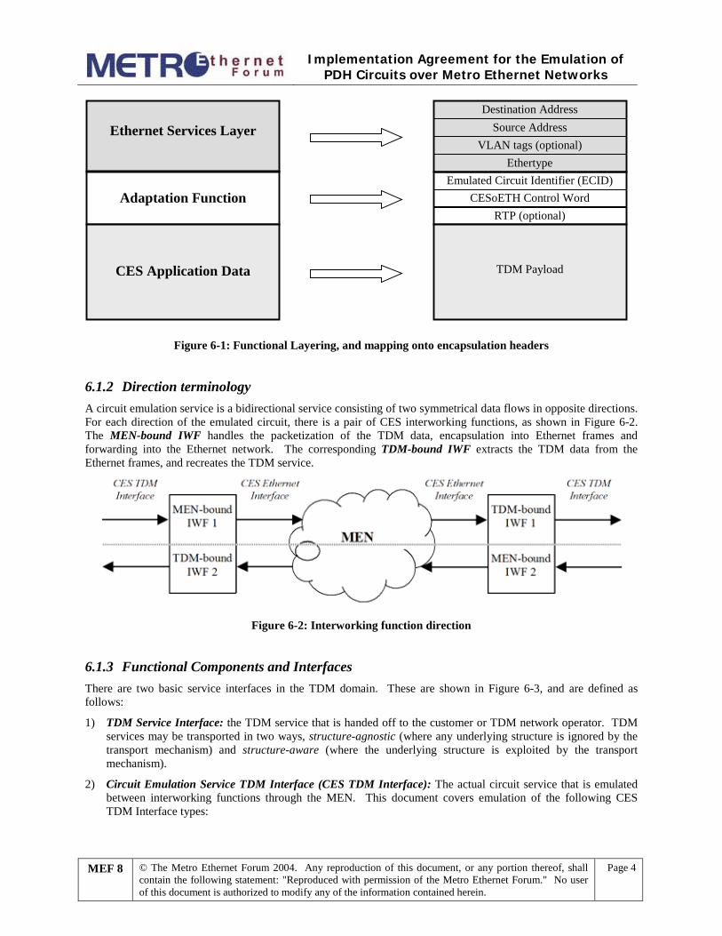
6.1.1 Functional Layering Circuit Emulation Services over Ethernet (CESoETH) uses a point-to-point connection between two CES interworking functions. Essentially it uses the MEN as an intermediate network (or “virtual wire”) between two TDM networks. This is handled as an application layer function in terms of layered network model defined in [MEF 4]. The CES IWF provides the adaptation of the CES application to the Ethernet services layer. The use of a VLAN tag is optional, and is restricted to the underlying MEN transport functions.
This functional layering is shown in Figure 6-1, with mapping onto the various encapsulation headers:
Implementation Agreement for the Emulation of
PDH Circuits over Metro Ethernet Networks
MEF 8 © The Metro Ethernet Forum 2004. Any reproduction of this document, or any portion thereof, shall contain the following statement: "Reproduced with permission of the Metro Ethernet Forum." No user of this document is authorized to modify any of the information contained herein.
Page 4
Destination AddressSource Address
EthertypeVLAN tags (optional)
Emulated Circuit Identifier (ECID)CESoETH Control Word
RTP (optional)
Ethernet Services Layer
Adaptation Function
CES Application Data TDM Payload
Figure 6-1: Functional Layering, and mapping onto encapsulation headers
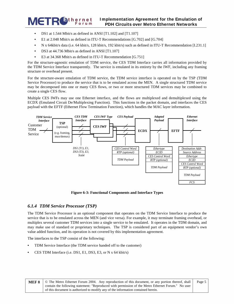
6.1.2 Direction terminology A circuit emulation service is a bidirectional service consisting of two symmetrical data flows in opposite directions. For each direction of the emulated circuit, there is a pair of CES interworking functions, as shown in Figure 6-2. The MEN-bound IWF handles the packetization of the TDM data, encapsulation into Ethernet frames and forwarding into the Ethernet network. The corresponding TDM-bound IWF extracts the TDM data from the Ethernet frames, and recreates the TDM service.
Figure 6-2: Interworking function direction
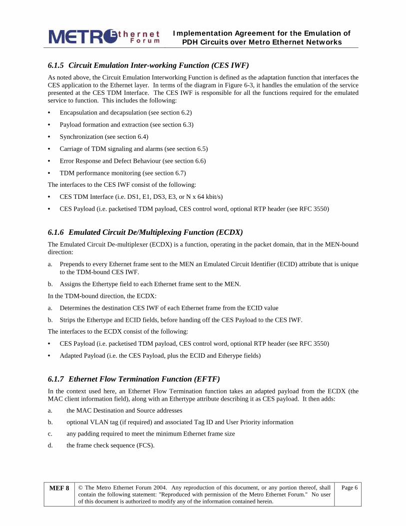
6.1.3 Functional Components and Interfaces There are two basic service interfaces in the TDM domain. These are shown in Figure 6-3, and are defined as follows:
1) TDM Service Interface: the TDM service that is handed off to the customer or TDM network operator. TDM services may be transported in two ways, structure-agnostic (where any underlying structure is ignored by the transport mechanism) and structure-aware (where the underlying structure is exploited by the transport mechanism).
2) Circuit Emulation Service TDM Interface (CES TDM Interface): The actual circuit service that is emulated between interworking functions through the MEN. This document covers emulation of the following CES TDM Interface types:
Implementation Agreement for the Emulation of
PDH Circuits over Metro Ethernet Networks
MEF 8 © The Metro Ethernet Forum 2004. Any reproduction of this document, or any portion thereof, shall contain the following statement: "Reproduced with permission of the Metro Ethernet Forum." No user of this document is authorized to modify any of the information contained herein.
Page 5
· DS1 at 1.544 Mbit/s as defined in ANSI [T1.102] and [T1.107] · E1 at 2.048 Mbit/s as defined in ITU-T Recommendations [G.702] and [G.704] · N x 64kbit/s data (i.e. 64 kbit/s, 128 kbit/s, 192 kbit/s) such as defined in ITU-T Recommendation [I.231.1] · DS3 at 44.736 Mbit/s as defined in ANSI [T1.107] · E3 at 34.368 Mbit/s as defined in ITU-T Recommendation [G.751]
For the structure-agnostic emulation of TDM service, the CES TDM Interface carries all information provided by the TDM Service Interface transparently. The service is emulated in its entirety by the IWF, including any framing structure or overhead present.
For the structure-aware emulation of TDM service, the TDM service interface is operated on by the TSP (TDM Service Processor) to produce the service that is to be emulated across the MEN. A single structured TDM service may be decomposed into one or many CES flows, or two or more structured TDM services may be combined to create a single CES flow.
Multiple CES IWFs may use one Ethernet interface, and the flows are multiplexed and demultiplexed using the ECDX (Emulated Circuit De/Multiplexing Function). This functions in the packet domain, and interfaces the CES payload with the EFTF (Ethernet Flow Termination Function), which handles the MAC layer information.
CustomerTDMService
CES TDMInterface
TDM ServiceInterface
TSP(optional)
(e.g. framing,mux/demux)
CES Payload
IWFIWF
CES IWF
CES IWF Type
EFTF
EthernetInterface
AdaptedPayload
DS1 (T1), E1,DS3 (T3), E3,
Nx64
CES Control WordRTP (optional)
TDM Payload
EthertypeECID
CES Control WordRTP (optional)
TDM Payload
Destination Addr.Source Address
EthertypeECID
CES Control WordRTP (optional)
TDM Payload
FCS
ECDX
Figure 6-3: Functional Components and Interface Types
6.1.4 TDM Service Processor (TSP) The TDM Service Processor is an optional component that operates on the TDM Service Interface to produce the service that is to be emulated across the MEN (and vice versa). For example, it may terminate framing overhead, or multiplex several customer TDM services into a single service to be emulated. It operates in the TDM domain, and may make use of standard or proprietary techniques. The TSP is considered part of an equipment vendor’s own value added function, and its operation is not covered by this implementation agreement.
The interfaces to the TSP consist of the following:
· TDM Service Interface (the TDM service handed off to the customer)
· CES TDM Interface (i.e. DS1, E1, DS3, E3, or N x 64 kbit/s)
Implementation Agreement for the Emulation of
PDH Circuits over Metro Ethernet Networks
MEF 8 © The Metro Ethernet Forum 2004. Any reproduction of this document, or any portion thereof, shall contain the following statement: "Reproduced with permission of the Metro Ethernet Forum." No user of this document is authorized to modify any of the information contained herein.
Page 6
6.1.5 Circuit Emulation Inter-working Function (CES IWF) As noted above, the Circuit Emulation Interworking Function is defined as the adaptation function that interfaces the CES application to the Ethernet layer. In terms of the diagram in Figure 6-3, it handles the emulation of the service presented at the CES TDM Interface. The CES IWF is responsible for all the functions required for the emulated service to function. This includes the following:
· Encapsulation and decapsulation (see section 6.2)
· Payload formation and extraction (see section 6.3)
· Synchronization (see section 6.4)
· Carriage of TDM signaling and alarms (see section 6.5)
· Error Response and Defect Behaviour (see section 6.6)
· TDM performance monitoring (see section 6.7)
The interfaces to the CES IWF consist of the following:
· CES TDM Interface (i.e. DS1, E1, DS3, E3, or N x 64 kbit/s)
· CES Payload (i.e. packetised TDM payload, CES control word, optional RTP header (see RFC 3550)
6.1.6 Emulated Circuit De/Multiplexing Function (ECDX) The Emulated Circuit De-multiplexer (ECDX) is a function, operating in the packet domain, that in the MEN-bound direction:
a. Prepends to every Ethernet frame sent to the MEN an Emulated Circuit Identifier (ECID) attribute that is unique to the TDM-bound CES IWF.
b. Assigns the Ethertype field to each Ethernet frame sent to the MEN.
In the TDM-bound direction, the ECDX:
a. Determines the destination CES IWF of each Ethernet frame from the ECID value
b. Strips the Ethertype and ECID fields, before handing off the CES Payload to the CES IWF.
The interfaces to the ECDX consist of the following:
· CES Payload (i.e. packetised TDM payload, CES control word, optional RTP header (see RFC 3550)
· Adapted Payload (i.e. the CES Payload, plus the ECID and Etherype fields)
6.1.7 Ethernet Flow Termination Function (EFTF) In the context used here, an Ethernet Flow Termination function takes an adapted payload from the ECDX (the MAC client information field), along with an Ethertype attribute describing it as CES payload. It then adds:
a. the MAC Destination and Source addresses
b. optional VLAN tag (if required) and associated Tag ID and User Priority information
c. any padding required to meet the minimum Ethernet frame size
d. the frame check sequence (FCS).

Implementation Agreement for the Emulation of
PDH Circuits over Metro Ethernet Networks
MEF 8 © The Metro Ethernet Forum 2004. Any reproduction of this document, or any portion thereof, shall contain the following statement: "Reproduced with permission of the Metro Ethernet Forum." No user of this document is authorized to modify any of the information contained herein.
Page 7
In the TDM-bound direction, the EFTF takes in an Ethernet frame from the MEN, and checks the FCS, discarding the frame if it is incorrect. It determines whether it contains CES payload from the Ethertype field, and forwards it to its associated ECDX function, for passing to the appropriate CES IWF.
The interfaces to the EFTF consist of the following:
· Adapted Payload (i.e. the CES Payload, plus the ECID and Etherype fields)
· Ethernet Interface (standard IEEE 802.3 interface)
6.2 ENCAPSULATION In common with IETF practice, the protocol descriptions in the following sections are in “network byte order”, where bit 0 is the most significant bit, and the bytes are transmitted most significant byte first (i.e. left to right in the figures shown in this document).
6.2.1 Ethernet Services Layer This consists of a standard layer 2 [IEEE 802.3]-compliant Ethernet MAC header, added by the EFTF (Ethernet Flow Termination component).
The assignment of the Ethernet source address is a matter of local policy. It is permitted for several IWFs to share a single Ethernet MAC sub-layer, or for each IWF to operate its own MAC sub-layer. The Ethernet destination address is set to the MAC address of the destination IWF.
Since the CESoETH adaptation function operates directly on top of the Ethernet layer without any intervening protocols, a separate “Ethertype” value must be allocated for CESoETH, in order to identify the protocol to a receiving device. The IEEE has assigned Ethertype 0x88d8 to identify Ethernet frames performing this CESoETH adaptation function.
6.2.2 Adaptation Function Headers There are three components to the adaptation function header:
1. Emulated Circuit Identifier – identifies the emulated circuit being carried. This separates the identification of the emulated circuit from the Ethernet layer, allowing the MEN operator to multiplex several emulated circuits across a single EVC where required. This is added by the ECDX.
2. CESoETH control word – provides sequencing and signaling of defects such as AIS of the TDM circuit, or packet loss detected in the MEN. This is added by the CES IWF.
3. Optional RTP header – Where appropriate, timing and sequencing may be provided by using the Real-time Transport Protocol, RTP [RFC 3550]. The default case is not to use RTP. This is added by the CES IWF.
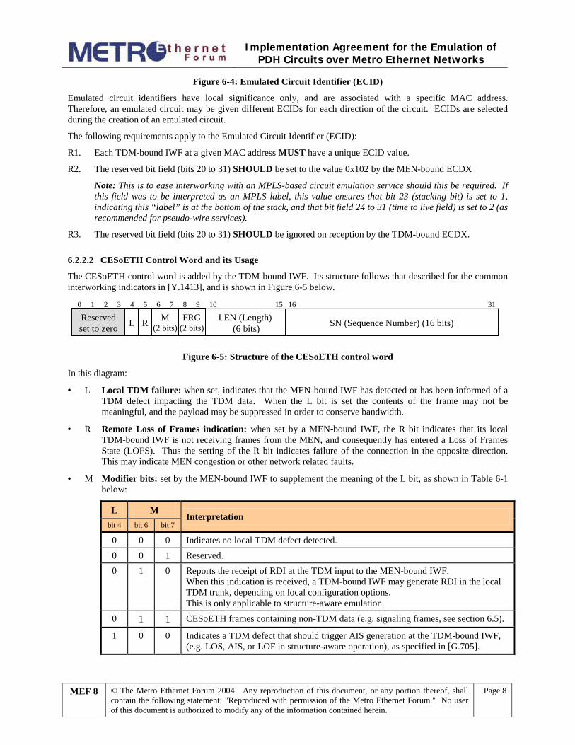
6.2.2.1 Emulated Circuit Identifier
The emulated circuit identifier (ECID) consists of a single, 20-bit unsigned binary field containing an identifier for the circuit being emulated. This is added by the ECDX, and shown in Figure 6-4 below.
Emulated Circuit Identifier (ECID) (20 bits) Reserved (set to 0x102)
0 19 20 31
Implementation Agreement for the Emulation of
PDH Circuits over Metro Ethernet Networks
MEF 8 © The Metro Ethernet Forum 2004. Any reproduction of this document, or any portion thereof, shall contain the following statement: "Reproduced with permission of the Metro Ethernet Forum." No user of this document is authorized to modify any of the information contained herein.
Page 8
Figure 6-4: Emulated Circuit Identifier (ECID)
Emulated circuit identifiers have local significance only, and are associated with a specific MAC address. Therefore, an emulated circuit may be given different ECIDs for each direction of the circuit. ECIDs are selected during the creation of an emulated circuit.
The following requirements apply to the Emulated Circuit Identifier (ECID):
R1. Each TDM-bound IWF at a given MAC address MUST have a unique ECID value.
R2. The reserved bit field (bits 20 to 31) SHOULD be set to the value 0x102 by the MEN-bound ECDX
Note: This is to ease interworking with an MPLS-based circuit emulation service should this be required. If this field was to be interpreted as an MPLS label, this value ensures that bit 23 (stacking bit) is set to 1, indicating this “label” is at the bottom of the stack, and that bit field 24 to 31 (time to live field) is set to 2 (as recommended for pseudo-wire services).
R3. The reserved bit field (bits 20 to 31) SHOULD be ignored on reception by the TDM-bound ECDX.
6.2.2.2 CESoETH Control Word and its Usage
The CESoETH control word is added by the TDM-bound IWF. Its structure follows that described for the common interworking indicators in [Y.1413], and is shown in Figure 6-5 below.
LEN (Length) (6 bits) SN (Sequence Number) (16 bits)
0 1 2 3 4 5 6 7 8 9 10 15 16 31
L R M(2 bits)
FRG(2 bits)
Reservedset to zero
Figure 6-5: Structure of the CESoETH control word
In this diagram:
· L Local TDM failure: when set, indicates that the MEN-bound IWF has detected or has been informed of a TDM defect impacting the TDM data. When the L bit is set the contents of the frame may not be meaningful, and the payload may be suppressed in order to conserve bandwidth.
· R Remote Loss of Frames indication: when set by a MEN-bound IWF, the R bit indicates that its local TDM-bound IWF is not receiving frames from the MEN, and consequently has entered a Loss of Frames State (LOFS). Thus the setting of the R bit indicates failure of the connection in the opposite direction. This may indicate MEN congestion or other network related faults.
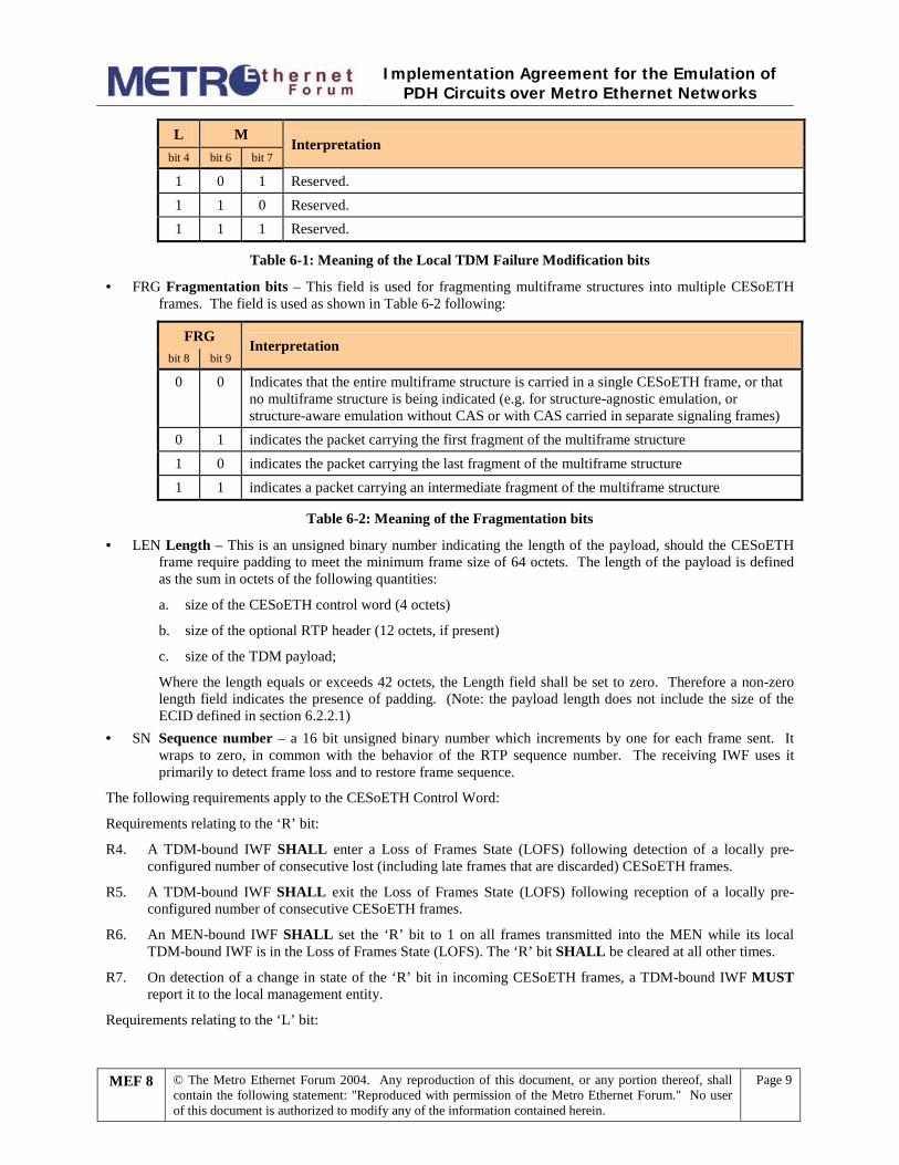
· M Modifier bits: set by the MEN-bound IWF to supplement the meaning of the L bit, as shown in Table 6-1 below:
L M Interpretation
bit 4 bit 6 bit 7
0 0 0 Indicates no local TDM defect detected. 0 0 1 Reserved. 0 1 0 Reports the receipt of RDI at the TDM input to the MEN-bound IWF.
When this indication is received, a TDM-bound IWF may generate RDI in the local TDM trunk, depending on local configuration options. This is only applicable to structure-aware emulation.
0 1 1 CESoETH frames containing non-TDM data (e.g. signaling frames, see section 6.5).
1 0 0 Indicates a TDM defect that should trigger AIS generation at the TDM-bound IWF, (e.g. LOS, AIS, or LOF in structure-aware operation), as specified in [G.705].
Implementation Agreement for the Emulation of
PDH Circuits over Metro Ethernet Networks
MEF 8 © The Metro Ethernet Forum 2004. Any reproduction of this document, or any portion thereof, shall contain the following statement: "Reproduced with permission of the Metro Ethernet Forum." No user of this document is authorized to modify any of the information contained herein.
Page 9
L M Interpretation
bit 4 bit 6 bit 7
1 0 1 Reserved. 1 1 0 Reserved. 1 1 1 Reserved.
Table 6-1: Meaning of the Local TDM Failure Modification bits
· FRG Fragmentation bits – This field is used for fragmenting multiframe structures into multiple CESoETH frames. The field is used as shown in Table 6-2 following:
FRG Interpretation
bit 8 bit 9
0 0 Indicates that the entire multiframe structure is carried in a single CESoETH frame, or that no multiframe structure is being indicated (e.g. for structure-agnostic emulation, or structure-aware emulation without CAS or with CAS carried in separate signaling frames)
0 1 indicates the packet carrying the first fragment of the multiframe structure 1 0 indicates the packet carrying the last fragment of the multiframe structure 1 1 indicates a packet carrying an intermediate fragment of the multiframe structure
Table 6-2: Meaning of the Fragmentation bits
· LEN Length – This is an unsigned binary number indicating the length of the payload, should the CESoETH frame require padding to meet the minimum frame size of 64 octets. The length of the payload is defined as the sum in octets of the following quantities:
a. size of the CESoETH control word (4 octets)
b. size of the optional RTP header (12 octets, if present)
c. size of the TDM payload;
Where the length equals or exceeds 42 octets, the Length field shall be set to zero. Therefore a non-zero length field indicates the presence of padding. (Note: the payload length does not include the size of the ECID defined in section 6.2.2.1)
· SN Sequence number – a 16 bit unsigned binary number which increments by one for each frame sent. It wraps to zero, in common with the behavior of the RTP sequence number. The receiving IWF uses it primarily to detect frame loss and to restore frame sequence.
The following requirements apply to the CESoETH Control Word:
Requirements relating to the ‘R’ bit:
R4. A TDM-bound IWF SHALL enter a Loss of Frames State (LOFS) following detection of a locally pre-configured number of consecutive lost (including late frames that are discarded) CESoETH frames.
R5. A TDM-bound IWF SHALL exit the Loss of Frames State (LOFS) following reception of a locally pre-configured number of consecutive CESoETH frames.
R6. An MEN-bound IWF SHALL set the ‘R’ bit to 1 on all frames transmitted into the MEN while its local TDM-bound IWF is in the Loss of Frames State (LOFS). The ‘R’ bit SHALL be cleared at all other times.
R7. On detection of a change in state of the ‘R’ bit in incoming CESoETH frames, a TDM-bound IWF MUST report it to the local management entity.
Requirements relating to the ‘L’ bit:
Implementation Agreement for the Emulation of
PDH Circuits over Metro Ethernet Networks
MEF 8 © The Metro Ethernet Forum 2004. Any reproduction of this document, or any portion thereof, shall contain the following statement: "Reproduced with permission of the Metro Ethernet Forum." No user of this document is authorized to modify any of the information contained herein.
Page 10
R8. For structure-agnostic emulation, an MEN-bound IWF MUST set the ‘L’ bit to one when loss of signal (LOS) is detected on the TDM service interface
R9. For structure-aware emulation, an MEN-bound IWF SHOULD set the ‘L’ bit to one where the TDM circuit indicates any of the following conditions:
a. Loss of Signal (LOS)
b. Alarm Indication Signal (AIS)
c. Loss of frame alignment (LOF)
R10. An MEN-bound IWF MUST clear the ‘L’ bit as soon as the defect condition is rectified.
R11. A CESoETH frame with the ‘L’ bit set to one MAY contain no TDM payload.
R12. For structure-agnostic emulation, on reception of CESoETH frames marked with the ‘L’ bit set to one, the TDM-bound IWF:
a. SHOULD discard the payload, and play out AIS code for the scheduled duration of the CESoETH frame.
b. Depending on the application, and where the TDM payload has not been suppressed it MAY play out the payload.
R13. For structure-aware emulation, on reception of CESoETH frames marked with the ‘L’ bit set to one, the TDM-bound IWF:
a. SHOULD discard the payload, and play out AIS for the scheduled duration of the CESoETH frame.
b. Depending on the application, it MAY generate trunk conditioning on the affected channels according to [TR-NWT-000170].
c. Depending on the application, and where the TDM payload has not been suppressed it MAY play out the payload.
Requirements relating to the ‘M’ field:
R14. A CES IWF (of either direction) MUST correctly support the conditions described for which the value of the ‘M’ field equals “00”. Support for any other condition is OPTIONAL.
R15. Where an MEN-bound IWF is not capable of detecting the conditions described in Table 6-1, it MUST clear the ‘M’ field to zero on frames to be transmitted into the MEN.
R16. A TDM-bound IWF MUST silently discard a CESoETH frame where the ‘M’ field is set to a value it does not support.
Requirements relating to the Sequence Number field:
R17. The SN field MUST be incremented by one for every CESoETH frame transmitted into the MEN with the same ECID value, including those frames that are fragments of multiframe structures.
R18. The initial value of the SN field on setup of an emulated circuit SHALL be random.
6.2.2.3 Optional RTP Header
Where RTP is used, CESoETH uses the fields of the RTP header [RFC 3550] in the following way:
Implementation Agreement for the Emulation of
PDH Circuits over Metro Ethernet Networks
MEF 8 © The Metro Ethernet Forum 2004. Any reproduction of this document, or any portion thereof, shall contain the following statement: "Reproduced with permission of the Metro Ethernet Forum." No user of this document is authorized to modify any of the information contained herein.
Page 11
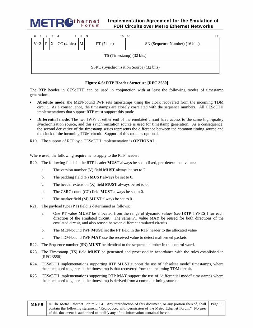
CC (4 bits)P X MV=2 PT (7 bits) SN (Sequence Number) (16 bits)
0 1 2 3 4 7 8 9 15 16 31
TS (Timestamp) (32 bits)
SSRC (Synchronization Source) (32 bits)
Figure 6-6: RTP Header Structure [RFC 3550]
The RTP header in CESoETH can be used in conjunction with at least the following modes of timestamp generation:
· Absolute mode: the MEN-bound IWF sets timestamps using the clock recovered from the incoming TDM circuit. As a consequence, the timestamps are closely correlated with the sequence numbers. All CESoETH implementations that support RTP must support this mode
· Differential mode: The two IWFs at either end of the emulated circuit have access to the same high-quality synchronization source, and this synchronization source is used for timestamp generation. As a consequence, the second derivative of the timestamp series represents the difference between the common timing source and the clock of the incoming TDM circuit. Support of this mode is optional.
R19. The support of RTP by a CESoETH implementation is OPTIONAL.
Where used, the following requirements apply to the RTP header:
R20. The following fields in the RTP header MUST always be set to fixed, pre-determined values:
a. The version number (V) field MUST always be set to 2.
b. The padding field (P) MUST always be set to 0.
c. The header extension (X) field MUST always be set to 0.
d. The CSRC count (CC) field MUST always be set to 0.
e. The marker field (M) MUST always be set to 0.
R21. The payload type (PT) field is determined as follows:
a. One PT value MUST be allocated from the range of dynamic values (see [RTP TYPES]) for each direction of the emulated circuit. The same PT value MAY be reused for both directions of the emulated circuit, and also reused between different emulated circuits
b. The MEN-bound IWF MUST set the PT field in the RTP header to the allocated value
c. The TDM-bound IWF MAY use the received value to detect malformed packets
R22. The Sequence number (SN) MUST be identical to the sequence number in the control word.
R23. The Timestamp (TS) field MUST be generated and processed in accordance with the rules established in [RFC 3550].
R24. CESoETH implementations supporting RTP MUST support the use of “absolute mode” timestamps, where the clock used to generate the timestamp is that recovered from the incoming TDM circuit.
R25. CESoETH implementations supporting RTP MAY support the use of “differential mode” timestamps where the clock used to generate the timestamp is derived from a common timing source.
Implementation Agreement for the Emulation of
PDH Circuits over Metro Ethernet Networks
MEF 8 © The Metro Ethernet Forum 2004. Any reproduction of this document, or any portion thereof, shall contain the following statement: "Reproduced with permission of the Metro Ethernet Forum." No user of this document is authorized to modify any of the information contained herein.
Page 12
R26. CESoETH implementations supporting RTP MUST support the use of “absolute mode” timestamps generated using an 8 kHz clock. Other frequencies that are integer multiples of 8 kHz MAY be used.
R27. CESoETH implementations supporting “differential mode” MUST support the use of timestamps generated using a 25 MHz clock. Other frequencies MAY be used providing they are:
a. Integer multiples of 8 kHz
b. Not an integer multiple of the clock frequency of the TDM circuit
R28. The synchronization source (SSRC) field MUST be generated and processed in accordance with the rules established in [RFC 3550].
R29. The SSRC field MAY be used by the TDM-bound IWF for the detection of misconnections.

Implementation Agreement for the Emulation of
PDH Circuits over Metro Ethernet Networks
MEF 8 © The Metro Ethernet Forum 2004. Any reproduction of this document, or any portion thereof, shall contain the following statement: "Reproduced with permission of the Metro Ethernet Forum." No user of this document is authorized to modify any of the information contained herein.
Page 13
6.3 PAYLOAD FORMATS This Implementation Agreement covers four payload formats:
1. Structure-agnostic emulation (section 6.3.1)
2. Octet-aligned payload for structure-agnostic emulation of DS1 circuits (section 6.3.1.1)
3. Structure-aware emulation using structure-locked encapsulation (section 6.3.2)
4. Structure-aware emulation using structure-indicated encapsulation (section 6.3.3)
Structure-agnostic emulation is the transport of unstructured TDM, or of structured TDM when the structure is completely disregarded by the transport mechanism. It maintains the precise bit sequence of data and any structure overhead that may be present, and provides no mechanisms for the location or utilization of a Frame Alignment Signal (FAS).
Structure-aware emulation is the transport of structured TDM taking at least some level of the structure into account. It is not required to carry all bits of the TDM bit-stream over the MEN; specifically, the FAS may be stripped at ingress and regenerated at egress.
R30. A CES IWF MUST support structure-agnostic emulation, as defined in section 6.3.1. The use of the octet-aligned payload format for DS1, or either of the structure-aware encapsulation formats is OPTIONAL.
6.3.1 Structure-Agnostic Emulation This implementation agreement defines the structure-agnostic emulation of the following TDM services:
· DS1, as defined in [G.702, T1.102]
· E1, as defined in [G.702]
· DS3, as defined in [G.702, T1.102]
· E3, as defined in [G.751]
The payload format is as described in [Y.1413], sub-clause 9.1. The following additional requirements also apply:
R31. CESoETH implementations MUST support at least the following TDM payload sizes where the indicated services are offered:
a. E1: 256 octets
b. DS1: 192 octets
c. E3: 1024 octets
d. DS3: 1024 octets.
The use of any other TDM payload size is OPTIONAL.
6.3.1.1 Octet-aligned Payload for Structure-Agnostic Emulation of DS1 Circuits
DS1 circuits may be delivered to the ingress IWF padded to an integer number of octets, as described in [G.802] Annex B. This padded data may be transported directly over the MEN using a payload format that consists of an integer number of 25-octet sub-frames, each sub-frame consisting of 193 bits of TDM data and 7 bits of padding. This is described in [Y.1413], sub-clause 9.1.1.
The following additional requirements apply:
R32. The TDM-bound IWF MUST NOT assume any alignment with the underlying DS1 framing structure
Implementation Agreement for the Emulation of
PDH Circuits over Metro Ethernet Networks
MEF 8 © The Metro Ethernet Forum 2004. Any reproduction of this document, or any portion thereof, shall contain the following statement: "Reproduced with permission of the Metro Ethernet Forum." No user of this document is authorized to modify any of the information contained herein.
Page 14
R33. CESoETH implementations supporting octet aligned DS1 MUST support a TDM payload size of 200 octets (including padding). The use of any other payload size is OPTIONAL.
6.3.2 Structure-Aware Emulation using Structure-Locked Encapsulation This implementation agreement defines the structure-aware emulation of the following TDM services using a “structure-locked” encapsulation, as described in [Y.1413], sub-clause 9.2.1:
· N x 64kbit/s “basic service”
· N x 64kbit/s service with Channel Associated Signaling (CAS) for the following specific TDM trunk types: · DS1 with framing according to the Extended Super Frame (ESF) format, as described in [T1.107]; or 24
frame multiframe as described in [G.704] · DS1 with framing according to the Super Frame (SF) format, as described in [T1.107]; or 12 frame
multiframe as described in [G.704] · E1 with framing according to the CRC-4 Multiframe format, as described in [G.704]
Note that application signaling such as CAS may also be transported using the generic method described in section 6.5.
The following general additional requirements apply:
R34. The timeslots to be placed into the payload need not be contiguous, and the payload MAY contain any combination of timeslots from the TDM circuit.
R35. The timeslots MUST be placed into the payload in the same order that they occur in the TDM circuit.
R36. A CESoETH implementation supporting structure-locked encapsulation MUST support values of N from 1 to 24 (where the TDM circuit is DS1) or from 1 to 31 (where the TDM circuit is E1).
R37. For implementations supporting structure-locked encapsulation, the support of N x 64kbit/s service with CAS is OPTIONAL.
The following additional requirements apply specifically to the support of N x 64kbit/s basic service using structure-locked encapsulation:
R38. A CESoETH structure-locked implementation supporting N x 64kbit/s basic service MAY support values of N larger than 31 (i.e. the implementation may be capable of selecting DS0s off multiple TDM circuits, where these TDM circuits are synchronous, or from a synchronous TDM bus system).
R39. A CESoETH structure-locked implementation supporting N x 64kbit/s basic service MUST support the following set of configurable packetization latency values:
a. For N ³ 5: 1 ms (with the corresponding TDM payload size of 8N octets)
b. For 2 £ N £ 4: 4 milliseconds (with the corresponding TDM payload size of 32N octets).
c. For N = 1: 8 milliseconds (with the corresponding TDM payload size of 64N octets).
Usage of any other packetization latency (TDM payload size) is OPTIONAL.
Note: these values increase for low values of N to avoid excessive inefficiency in the bandwidth utilisation. For example, for N=5, the payload size is 40 octets, which results in a bandwidth efficiency of only 60% due to the size of the header and FCS (26 octets).
The following additional requirements apply specifically to the support of N x 64kbit/s service with CAS using structure-locked encapsulation:
R40. The payload structure MUST be composed of exactly M TDM frames, plus one signaling sub-structure. Specifically for each type of TDM trunk:
Implementation Agreement for the Emulation of
PDH Circuits over Metro Ethernet Networks
MEF 8 © The Metro Ethernet Forum 2004. Any reproduction of this document, or any portion thereof, shall contain the following statement: "Reproduced with permission of the Metro Ethernet Forum." No user of this document is authorized to modify any of the information contained herein.
Page 15
a. For DS1 with ESF multiframes, M = 24 (one ESF, or 24 frame multiframe)
b. For DS1 with SF multiframes, M = 24 (two SFs, or two 12-frame multiframes)
c. For E1 with CRC-4 multiframes, M = 16 (one CRC-4 multiframe)
R41. The format of the signaling sub-structures for each specific TDM trunk MUST be as defined in [ATM-CES], section 2.3.1.2.
R42. Each CESoETH frame MUST carry the same number of TDM frames of data, regardless of whether it contains the signaling sub-structure or not.
R43. In case of a DS1 circuit, the signaling bits are carried in the TDM data as well as in the signaling sub-structure. However, the TDM-bound IWF MUST use the CAS bits carried in the signaling sub-structures.
Note: there is no guarantee of alignment between the 24-frame structure carried in the payload, and the multiframe structure of the DS1 circuit. Hence there is no way of determining which are the signaling bits.
R44. All CESoETH structure-locked implementations supporting trunk-specific Nx64kbit/s with CAS MUST support the default mode where a single CESoETH packet carries exactly one payload structure, with one signaling sub-structure.
6.3.3 Structure-Aware Emulation using Structure-Indicated Encapsulation This implementation agreement defines the structure-aware emulation of the following TDM services using a “structure-indicated” encapsulation, as described in [Y.1413], sub-clause 9.2.2:
· N x 64kbit/s “basic service”
· N x 64kbit/s service with Channel Associated Signaling (CAS) for the following specific TDM trunk types: · DS1 with framing according to the Extended Super Frame (ESF) format, as described in [T1.107]; or 24
frame multiframe as described in [G.704] · DS1 with framing according to the Super Frame (SF) format, as described in [T1.107]; or 12 frame
multiframe as described in [G.704] · E1 with framing according to the CRC-4 Multiframe format, as described in [G.704]
This encapsulation first adapts the TDM bit stream using AAL Type 1, as defined in [I.363.1] and [ATM-CES].
The following additional requirements apply:
R45. All compliant implementations that support structure-indicated encapsulation for DS1 and E1 service MUST support 1 AAL1 PDU per frame, and SHOULD support from 2 to 8 AAL1 PDUs per frame.
Support for more PDUs per frame is OPTIONAL.
R46. For implementations supporting structure-indicated encapsulation, the support of N x 64kbit/s service with CAS is OPTIONAL.
Note: the AAL type 1 adaptation described here may also be used for structure-agnostic transport. Examples where this may be beneficial are when interworking with ATM-based circuit emulation systems, or when SRTS-based clock recovery is used. When this is used for DS3 or E3 service, it is recommended that implementations support from 4 to 15 AAL1 PDUs per frame.
6.4 SYNCHRONIZATION Synchronization is an important consideration in any circuit emulation scheme. Put simply, the clock used to play out the data at the TDM-bound IWF must be the same frequency as the clock used to input the data at the MEN-bound IWF, otherwise frame slips will occur over time. Architectures for synchronization and clock recovery are discussed in more detail in [MEF 3].
Implementation Agreement for the Emulation of
PDH Circuits over Metro Ethernet Networks
MEF 8 © The Metro Ethernet Forum 2004. Any reproduction of this document, or any portion thereof, shall contain the following statement: "Reproduced with permission of the Metro Ethernet Forum." No user of this document is authorized to modify any of the information contained herein.
Page 16
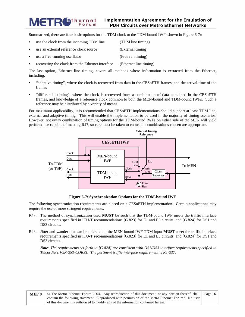
Summarized, there are four basic options for the TDM clock to the TDM-bound IWF, shown in Figure 6-7::
· use the clock from the incoming TDM line (TDM line timing)
· use an external reference clock source (External timing)
· use a free-running oscillator (Free run timing)
· recovering the clock from the Ethernet interface (Ethernet line timing)
The last option, Ethernet line timing, covers all methods where information is extracted from the Ethernet, including:
· “adaptive timing”, where the clock is recovered from data in the CESoETH frames, and the arrival time of the frames
· “differential timing”, where the clock is recovered from a combination of data contained in the CESoETH frames, and knowledge of a reference clock common to both the MEN-bound and TDM-bound IWFs. Such a reference may be distributed by a variety of means.
For maximum applicability, it is recommended that CESoETH implementations should support at least TDM line, external and adaptive timing. This will enable the implementation to be used in the majority of timing scenarios. However, not every combination of timing options for the TDM-bound IWFs on either side of the MEN will yield performance capable of meeting R47, so care must be taken to ensure the combinations chosen are appropriate.
To MEN
Data
To TDM(or TSP)
Clock
Data
Clock
MEN-boundIWF
CESoETH IWF
Ext.
FreeRun
Data
TDMLine
External TimingReference
TDM-boundIWF
Eth.Line Clock
Recovery
Clock
Figure 6-7: Synchronization Options for the TDM-bound IWF
The following synchronization requirements are placed on a CESoETH implementation. Certain applications may require the use of more stringent requirements.
R47. The method of synchronization used MUST be such that the TDM-bound IWF meets the traffic interface requirements specified in ITU-T recommendations [G.823] for E1 and E3 circuits, and [G.824] for DS1 and DS3 circuits.
R48. Jitter and wander that can be tolerated at the MEN-bound IWF TDM input MUST meet the traffic interface requirements specified in ITU-T recommendations [G.823] for E1 and E3 circuits, and [G.824] for DS1 and DS3 circuits.
Note: The requirements set forth in [G.824] are consistent with DS1/DS3 interface requirements specified in Telcordia’s [GR-253-CORE]. The pertinent traffic interface requirement is R5-237.
Implementation Agreement for the Emulation of
PDH Circuits over Metro Ethernet Networks
MEF 8 © The Metro Ethernet Forum 2004. Any reproduction of this document, or any portion thereof, shall contain the following statement: "Reproduced with permission of the Metro Ethernet Forum." No user of this document is authorized to modify any of the information contained herein.
Page 17
6.5 TDM APPLICATION SIGNALING CE applications interconnected over a CESoETH service may exchange signaling in addition to TDM data. The typical example is telephony applications that exchange their state (e.g. off-hook/on-hook) in addition to TDM data carrying PCM-encoded voice.
With structure-agnostic emulation, it is not required to intercept or process CE signaling. Signaling is embedded in the TDM data stream, and hence it is carried end-to-end across the emulated circuit.
With structure-aware emulation, transport of Common Channel Signaling (CCS) may be achieved by carrying the signaling channel with the emulated service (e.g. channel 23 for DS1, or channel 16 for E1). However, Channel Associated Signaling (CAS) (e.g. DS1 Robbed Bit Signaling or E1 CAS) requires knowledge of the relationship of the timeslot to the trunk multi-frame structure. This is indicated by the framing bits, which may not be preserved by N x 64 kbit/s basic service.
This section describes a generic method for extending the Nx64kbit/s basic service by carrying CE signaling (CAS or CCS) in separate signaling packets that is independent of the TDM circuit type. It may be used in situations where the individual 64kbit/s channels are selected from multiple TDM circuits, or picked off a TDM bus rather than from a specific TDM circuit. It also saves MEN bandwidth, since only changes in the CE application state are carried.
6.5.1 CE Signaling Frames The generic format of the CE signaling frames corresponds to the format shown in Figure 6-1 and the requirements expressed in section 6.2. The following additional requirements apply:
R49. CESoETH data frames and their associated signaling frames MUST have the same:
a. Destination MAC address
b. Ethertype
c. Usage of the RTP header (i.e. either both use it or both do not use it).
R50. CESoETH data frames and their associated signaling frames MUST use different ECID values.
Note: Establishment of correspondence between the ECIDs used by the matching data and signaling frames is outside the scope of this Implementation Agreement.
R51. CESoETH data frames and their associated signaling frames MUST use a separate sequence number space.
R52. If the RTP header is used:
a. Data frames and associated signaling frames MUST use a different payload type value (both allocated from the range of dynamically allocated RTP payload types).
b. Data frames and associated signaling frames MUST use a different SSRC value.
c. The timestamp values for the data and associated signaling frames MUST be identical at any given time.
Note: This enables synchronization of the signaling and data information using the standard RT-based mixing procedures described in [RFC 3550].
6.5.2 Channel Associated Signaling (CAS) Frames In the case where the CE application interconnected by a basic Nx64kbit/s CESoETH service is a telephony application using Channel Associated Signaling (CAS), the following additional rules apply to generation and processing of signaling packets:
Implementation Agreement for the Emulation of
PDH Circuits over Metro Ethernet Networks
MEF 8 © The Metro Ethernet Forum 2004. Any reproduction of this document, or any portion thereof, shall contain the following statement: "Reproduced with permission of the Metro Ethernet Forum." No user of this document is authorized to modify any of the information contained herein.
Page 18
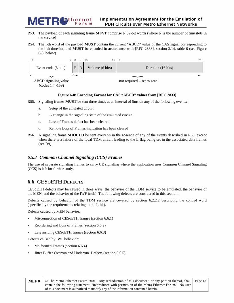
R53. The payload of each signaling frame MUST comprise N 32-bit words (where N is the number of timeslots in the service)
R54. The i-th word of the payload MUST contain the current “ABCD” value of the CAS signal corresponding to the i-th timeslot, and MUST be encoded in accordance with [RFC 2833], section 3.14, table 6 (see Figure 6-8, below)
Volume (6 bits) Duration (16 bits)
0 7 8 9 10 15 16 31
EEvent code (8 bits) R
not required – set to zeroABCD signaling value(codes 144-159)
Figure 6-8: Encoding Format for CAS “ABCD” values from [RFC 2833]
R55. Signaling frames MUST be sent three times at an interval of 5ms on any of the following events:
a. Setup of the emulated circuit
b. A change in the signaling state of the emulated circuit.
c. Loss of Frames defect has been cleared
d. Remote Loss of Frames indication has been cleared
R56. A signaling frame SHOULD be sent every 5s in the absence of any of the events described in R55, except when there is a failure of the local TDM circuit leading to the L flag being set in the associated data frames (see R9).
6.5.3 Common Channel Signaling (CCS) Frames The use of separate signaling frames to carry CE signaling where the application uses Common Channel Signaling (CCS) is left for further study.
6.6 CESOETH DEFECTS CESoETH defects may be caused in three ways: the behavior of the TDM service to be emulated, the behavior of the MEN, and the behavior of the IWF itself. The following defects are considered in this section:
Defects caused by behavior of the TDM service are covered by section 6.2.2.2 describing the control word (specifically the requirements relating to the L-bit).
Defects caused by MEN behavior:
· Misconnection of CESoETH frames (section 6.6.1)
· Reordering and Loss of Frames (section 6.6.2)
· Late arriving CESoETH frames (section 6.6.3)
Defects caused by IWF behavior:
· Malformed Frames (section 6.6.4)
· Jitter Buffer Overrun and Underrun Defects (section 6.6.5)
Implementation Agreement for the Emulation of
PDH Circuits over Metro Ethernet Networks
MEF 8 © The Metro Ethernet Forum 2004. Any reproduction of this document, or any portion thereof, shall contain the following statement: "Reproduced with permission of the Metro Ethernet Forum." No user of this document is authorized to modify any of the information contained herein.
Page 19
6.6.1 Misconnection Should a frame be wrongly directed to a CES IWF, it is possible for it to be mis-interpreted as a genuine CESoETH frame, especially if the first word of the payload match a known emulated circuit ID value. In order to detect such “stray frames”, the following rules should be applied:
R57. The CES IWF MUST only accept frames that contain the correct Ethernet destination address field and ECID value for that IWF.
R58. The CES IWF SHOULD provide additional protection by checking the Ethernet source address field against the known source address of the given emulated circuit ID.
R59. Where RTP is being used, further protection MAY be provided by checking the value of the SSRC field against the known SSRC value of the given emulated circuit ID.
R60. When a stray frame is detected by a CES IWF, it MUST be discarded.
R61. If the percentage of stray frames persists above a defined level for a configurable period of time (by default, 2.5 seconds), the Misconnection alarm SHOULD be reported to the management system.
R62. The Misconnection alarm SHOULD be cleared if no stray frames have been detected for a configurable period of time (by default, 10 seconds).
R63. The mechanisms for detection of lost frames (e.g. expected next sequence number) MUST NOT be affected by reception of stray frames.
6.6.2 Reordering and Loss of Frames Detection of out-of-sequence or lost CESoETH frames is accomplished by use of the sequence number, either from the RTP header or the CESoETH control word. The following rules apply to re-ordering and lost frames.
R64. Emulated circuits that use the RTP header MUST use the sequence number from the CESoETH control word, and ignore the sequence number (if any) in the RTP header.
R65. CESoETH implementations SHOULD attempt to re-order out-of-sequence frames where they arrive in time to be played out
R66. Out-of-sequence CESoETH frames that cannot be re-ordered MUST be discarded, and considered as lost.
R67. If loss of one or more CESoETH frames is detected by the TDM-bound IWF, it MUST generate exactly one “replacement octet” for every lost octet of TDM data.
R68. All CESoETH implementations SHOULD support the following methods of generating replacement data:
a. For structure-agnostic service, generate AIS code for the scheduled duration of the CESoETH frame.
b. For Nx64kbit/s service with and without CAS, generate locally configured idle code for the scheduled duration of the CESoETH frame.
c. For Nx64kbit/s service with CAS, use either the previous value of the CAS data, or a pre-defined value for each of the 64kbit/s channels.
Depending on the application, other methods of generating replacement data MAY be used (e.g. frame loss concealment techniques, or replay of the last received CESoETH frame).
R69. If the Frame Loss Ratio (as defined in [MEF 5]) persists above a defined threshold for a configurable period of time (by default, 2.5 seconds), a Loss of Frames alarm SHOULD be sent to the management system.
R70. The Loss of Frames alarm SHOULD be cleared if Frame Loss Ratio remains below a defined threshold for a configurable period of time (by default, 10 seconds).
Implementation Agreement for the Emulation of
PDH Circuits over Metro Ethernet Networks
MEF 8 © The Metro Ethernet Forum 2004. Any reproduction of this document, or any portion thereof, shall contain the following statement: "Reproduced with permission of the Metro Ethernet Forum." No user of this document is authorized to modify any of the information contained herein.
Page 20
6.6.3 Late Arriving Frames On occasions, the frame delay variation may be abnormally large, leading to CESoETH frames arriving after their scheduled playout time, although the jitter buffer may not necessarily be full. These frames are effectively lost, and may already have been considered as lost frames.
The following requirements apply to late arriving frames:
R71. A CESoETH IWF MUST discard frames that arrive too late to be played out on the TDM interface.
R72. If the percentage of frames arriving too late to be played out exceeds a defined level for a configurable period of time (by default, 2.5 seconds), a Late Frame alarm SHOULD be sent to the management system.
R73. The Late Frame alarm SHOULD be cleared if the percentage of frames arriving too late to be played out stays under a defined threshold for a configurable period of time (by default, 10 seconds).
6.6.4 Malformed CESoETH Frames A malformed CESoETH frame is one that is not a stray frame and either or both of the following conditions apply:
· If RTP is used, the PT value in its RTP header does not correspond to one of the PT values allocated for this direction of the emulated circuit.
· For CESoETH frames containing valid TDM data with the defect indicator L=0, and for which the actual payload size can be unambiguously determined, the payload size does not match the size defined for this flow.
R74. If a malformed frame is received by the TDM-bound IWF in time to be played out to the TDM interface, it SHOULD:
a. Discard the malformed frame
b. generate exactly one “replacement octet” for every lost octet of TDM data
R75. All CESoETH implementations SHOULD support the following methods of generating data to replace a malformed frame:
a. For structure-agnostic service, generate AIS code for the scheduled duration of the CESoETH frame.
b. For Nx64kbit/s service with and without CAS, generate locally configured idle code for the scheduled duration of the CESoETH frame.
c. For Nx64kbit/s service with CAS, use either the previous value of the CAS data, or a pre-defined value for each of the 64kbit/s channels
Depending on the application, other methods of generating replacement data MAY be used (e.g. frame loss concealment techniques, or replay of the last received CESoETH frame).
R76. If the percentage of malformed CESoETH frames persists above a defined level for a configurable period of time (by default, 2.5 seconds), a Malformed Frames alarm SHOULD be sent to the management system.
R77. The Malformed Frames alarm SHOULD be cleared if no malformed packets have been detected for a configurable period of time (by default, 10 seconds).
6.6.5 Jitter Buffer Overrun and Underrun Defects The TDM-bound IWF contains a “jitter buffer” that accumulates data from incoming CESoETH frames. The main purpose of this jitter buffer is to smooth out variation in arrival time of the CESoETH frames. Data is played out of the jitter buffer onto the TDM service at constant rate. The delay through this buffer needs to be as small as possible, in order to reduce latency of the TDM service, but large enough to absorb known variation in the frame delay (FDV, sometimes known as “frame jitter”, see [MEF 5]).
Implementation Agreement for the Emulation of
PDH Circuits over Metro Ethernet Networks
MEF 8 © The Metro Ethernet Forum 2004. Any reproduction of this document, or any portion thereof, shall contain the following statement: "Reproduced with permission of the Metro Ethernet Forum." No user of this document is authorized to modify any of the information contained herein.
Page 21
However, there may be occasions when the frame delay variation is abnormally large, and either overrun or underrun conditions may occur. These conditions may also occur when the clock used for playout of the TDM data from the jitter buffer is not at precisely the same frequency as the original TDM service clock presented to the MEN-bound IWF.
The Jitter Buffer Overrun condition occurs when the jitter buffer at the TDM-bound IWF cannot accommodate the newly arrived valid CESoETH frame in its entirety, e.g. due to insufficient storage space. The Jitter Buffer Underrun condition occurs when there is no correctly received CESoETH payload ready to be played out on the TDM interface, and replacement data must be played out instead. Primarily this occurs due to frames lost in the MEN, or discarded due to error conditions, hence this is not usually identified separately.
The following requirements apply to the detection of jitter buffer defects:
R78. A CESoETH IWF MUST detect the Jitter Buffer Overrun conditions.
R79. If a CESoETH frame arrives that cannot be stored in the jitter buffer due to a jitter buffer overrun condition, the TDM-bound IWF MUST discard the frame.
R80. If the percentage of frames causing Jitter Buffer Overruns persists above a defined level for a configurable period of time (by default, 2.5 seconds), a Jitter Buffer Overrun alarm SHOULD be sent to the management system.
R81. The Jitter Buffer Overrun alarm SHOULD be cleared if no cases of jitter buffer overrun have been detected for a configurable period of time (by default, 10 seconds).
6.7 PERFORMANCE MONITORING
6.7.1 Facility Data Link R82. CESoETH implementations supporting DS1 circuit using ESF framing MAY monitor messages carried in
the FDL (Facility Data Link). For example, it may be required to monitor Performance Report Messages, as described in [T1.403].
R83. CESoETH implementations supporting DS1 circuit using ESF framing MUST NOT change messages carried in the FDL (Facility Data Link), or insert new messages.
6.7.2 Errored Data References [T1.510] and [G.826] define the concept of an errored second and severely errored second. These measures are used to monitor the integrity of the TDM connection. All events in the TDM-bound IWF which lead to replacement data being played out (except when a result of receiving a CESoETH packet with an AIS or Idle Code indication) give rise to errored seconds (or potentially, severely errored seconds.
The collective sum of all these errors can be aggregated into a single measure termed “Frame Error Ratio” (FER), defined in [MEF 3] as the number of errored (i.e. lost or discarded) CESoETH frames, over the total number of CESoETH frames sent. This is similar to the “overall loss ratio” defined for voice services over IP networks in [G.1020]. This includes situations where the CESoETH frame:
a. fails to arrive at the TDM-bound IWF (i.e. is lost in MEN)
b. arrives too late to be played out
c. arrives too early to be accommodated in the jitter buffer
d. arrives with bit errors causing the frame to be discarded
The following requirements apply to monitoring of the FER:
Implementation Agreement for the Emulation of
PDH Circuits over Metro Ethernet Networks
MEF 8 © The Metro Ethernet Forum 2004. Any reproduction of this document, or any portion thereof, shall contain the following statement: "Reproduced with permission of the Metro Ethernet Forum." No user of this document is authorized to modify any of the information contained herein.
Page 22
R84. A CESoETH implementation SHOULD be capable of monitoring the Frame Error Ratio (FER) performance of the CESoETH connection.
7. Service Initiation and Operation
7.1 COMMON CONSIDERATIONS Edge-to-edge service emulation of a TDM service using CESoETH assumes the following elements:
· Two end services of the same type and bit rate
· Packetizer at the MEN-bound CES IWF
· Jitter buffer and de-packetizer at the TDM-bound CES IWF.
Setup and teardown of CESoETH emulated circuits is based on exchange of service parameters between the two CES IWFs at either end of the emulated circuit. This may be done manually, or using an auto-negotiation process. The nature of a suitable auto-negotiation process is for further study.
7.2 CESOETH SERVICE PARAMETERS The following parameters need to be assigned when an emulated circuit is set up.
1) Service Type The following service types are defined for CESoETH services. The service type must be the same for each direction of the emulated circuit (i.e. no service interworking is peformed). · Structure-agnostic E1 · Structure-agnostic DS1 · Structure-agnostic E3 · Structure-agnostic DS3 · Nx64kbit/s Basic Service using structure-locked encapsulation · Nx64kbit/s Basic Service using structure-indicated encapsulation · E1 Nx64kbit/s with CAS using structure-locked encapsulation · E1 Nx64kbit/s with CAS using structure-indicated encapsulation · DS1 (ESF) Nx64kbit/s with CAS using structure-locked encapsulation · DS1 (ESF) Nx64kbit/s with CAS using structure-indicated encapsulation · DS1 (SF) Nx64kbit/s with CAS using structure-locked encapsulation · DS1 (SF) Nx64kbit/s with CAS using structure-indicated encapsulation
2) TDM Bit Rate For structure-aware N x 64kbit/s services of any encapsulation type, this is defined as the number of 64 kbit/s channels carried by the emulated circuit (i.e. the value of N). It is the same for each direction of the emulated circuit. This parameter is not applicable for structure-agnostic emulation.
3) Payload size
Implementation Agreement for the Emulation of
PDH Circuits over Metro Ethernet Networks
MEF 8 © The Metro Ethernet Forum 2004. Any reproduction of this document, or any portion thereof, shall contain the following statement: "Reproduced with permission of the Metro Ethernet Forum." No user of this document is authorized to modify any of the information contained herein.
Page 23
This is defined as the number of octets of TDM payload carried in each CESoETH frame. It is the same for each direction of the emulated circuit.
For structure-aware, structure-locked encapsulation of N x 64kbit/s service with CAS (section 6.3.2), this EXCLUDES the CAS sub-structure carried in the last frame of every structure.
For structure-indicated encapsulation (section 6.3.3), this parameter is 48 times the number of AAL1 PDUs per CESoETH frame.
4) Emulated Circuit Identifier (ECID) A 20-bit value identifying the emulated circuit being carried. It is defined according to the rules specified in section 6.2.2.1. A separate ECID is assigned for each direction of the emulated circuit.
5) TDM clock source for the TDM-bound IWF Section 6.4 describes the various clocking options for the TDM-bound IWF. These may be different for the IWFs on either side of the MEN. Operators must ensure that the combination of options chosen meets the synchronization quality target for the application.
6) RTP This boolean parameter specifies whether the RTP header is to be used or not.
7) Use of Generic TDM Application Signaling Method Boolean value specifying whether the generic TDM application signaling method described in section 6.5 is to be used or not.
8) Use of an extended 64-bit control word Boolean value specifying whether the control word is to be extended from 32 bits to 64. Where an extended control word is selected, the extension applies to both directions of the emulated circuit, and remains unchanged throughout the lifetime of the circuit. The definition of the bits in the extended control word is reserved.
The following additional parameters need to be assigned if RTP is used:
9) Payload Type The value to be used for the Payload Type field, as described in section 6.2.2.3.
10) Timestamp mode This parameter defines the mode to be used for generation of the RTP timestamp. It may take two values, “absolute” or “differential”, as described in section 6.2.2.3.
11) Timestamp resolution This parameter encodes the bit rate of the clock used for setting the timestamps in RTP headers as a multiple of the basic 8kHz rate (e.g. a bit rate clock for an E1 circuit would be encoded as 256).
12) SSRC Value The value to be used for the SSRC field, as described in section 6.2.2.3.
The following additional parameters need to be assigned if generic TDM signaling (section 6.5) is used:
Implementation Agreement for the Emulation of
PDH Circuits over Metro Ethernet Networks
MEF 8 © The Metro Ethernet Forum 2004. Any reproduction of this document, or any portion thereof, shall contain the following statement: "Reproduced with permission of the Metro Ethernet Forum." No user of this document is authorized to modify any of the information contained herein.
Page 24
13) Emulated Circuit Identifier (ECID) for signaling frames A 20-bit value identifying the emulated circuit being carried. It is defined according to the rules specified in section 6.2.2.1.
14) Payload Type The value to be used for the Payload Type field in signaling frames, as described in section 6.2.2.3.
15) SSRC Value The value to be used for the SSRC field in signaling frames, as described in section 6.2.2.3.
7.3 CESOETH LOCAL CONFIGURATION PARAMETERS The following parameters are configured locally:
1) Control Word Parameters (see Section 6.2.2.2)
· Number of consecutive lost frames after which the ‘R’ flag is set in the control word (see R4) · Number of consecutive received frames after which the ‘R’ flag is cleared in the control word (see R5) · Action on receipt of frame containing the ‘R’ flag set (see R6) · Conditions that will cause the ‘L’ flag to be set in the control word (see R9) · Payload suppression on packets with ‘L’ bit set (see R11) · Action on receipt of frame containing the ‘L’ flag set (see R12, R13) · Action on receipt of a packet containing ‘L’=0, ‘M’=10 (see Table 6-1)
2) Defect and Alarm Parameters
· Replacement data for lost or discarded frames (see R68, R75)
The following locally configured parameters are applicable to all defect alarms:
· Duration of high defect level after which the relevant alarm is triggered (default is 2.5s) · Duration of low defect level after which the relevant alarm is cleared (default is 10s)
The following locally configured parameters are relevant to the triggering of the individual defect alarms:
· Percentage of misconnection occurrences above which the Misconnection alarm is triggered (see R61) · Frame loss ratio above which the Loss of Frames alarm is triggered (see R69) · Percentage of late arriving frame occurrences above which the Late Frame alarm is triggered (see R72) · Percentage of malformed frame occurrences above which the Malformation alarm is triggered (see R76) · Percentage of jitter buffer overrun occurrences above which the Jitter Buffer Overrun alarm is triggered
(see R80)
The following locally configured parameters are relevant to the clearing of the individual defect alarms. The remainder of the alarms are cleared by a period of absence of the alarm condition.
· Frame loss ratio below which the Loss of Frames alarm is cleared (see R70) · Percentage of late arriving frame occurrences below which the Late Frame alarm is cleared (see R73)

Implementation Agreement for the Emulation of
PDH Circuits over Metro Ethernet Networks
MEF 8 © The Metro Ethernet Forum 2004. Any reproduction of this document, or any portion thereof, shall contain the following statement: "Reproduced with permission of the Metro Ethernet Forum." No user of this document is authorized to modify any of the information contained herein.
Page 25
8. MEN Requirements
8.1 MEN SERVICE TYPE Both “T-Line” and “TALS” versions of the CESoETH service are run across point-to-point EVCs (i.e. across an E-Line service type). In the simplest case of a pair of IWFs connected by an E-Line service, the Ethernet service resembles an EPL (Ethernet Private Line). However, in many cases several IWFs may share an Ethernet UNI (and in fact, several IWFs could also share an EVC). Therefore in general the Ethernet service required more closely resembles an EVPL (Ethernet Virtual Private Line). Both the EPL and EVPL services are normatively described in [MEF 6].
Figure 8-1 shows a typical configuration where several small sites may be connected to some larger sites over point-to-point EVCs. Any service multiplexing is performed in the TDM domain as part of the TSP (TDM Service Processing) function.
Figure 8-1: Example TDM Virtual Private Line Configurations
8.2 SERVICE ATTRIBUTES Table 6-1 shows typical values of the service attributes for the underlying Ethernet service used to carry the CESoETH application (see [MEF 1 and [MEF 6]:
UNI Service Attribute Service Attribute Parameters and Values UNI Identifier Arbitrary text string to identify the UNI. Physical Medium IEEE 802.3-2002 Physical Interface Speed 10 Mbps, 100 Mbps, 1 Gbps or 10 Gbps Mode Full Duplex MAC Layer IEEE 802.3-2002 Service Multiplexing Yes (if multiple EVCs are supported on the same UNI)
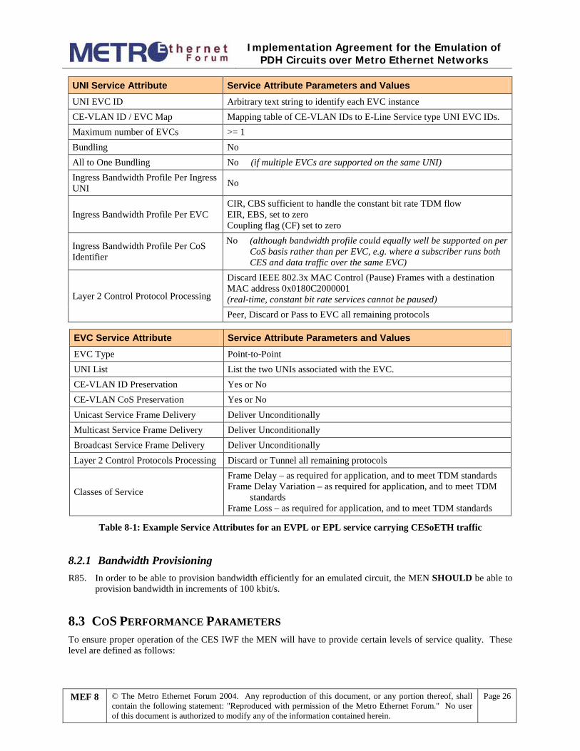
Implementation Agreement for the Emulation of
PDH Circuits over Metro Ethernet Networks
MEF 8 © The Metro Ethernet Forum 2004. Any reproduction of this document, or any portion thereof, shall contain the following statement: "Reproduced with permission of the Metro Ethernet Forum." No user of this document is authorized to modify any of the information contained herein.
Page 26
UNI Service Attribute Service Attribute Parameters and Values UNI EVC ID Arbitrary text string to identify each EVC instance CE-VLAN ID / EVC Map Mapping table of CE-VLAN IDs to E-Line Service type UNI EVC IDs. Maximum number of EVCs >= 1 Bundling No All to One Bundling No (if multiple EVCs are supported on the same UNI) Ingress Bandwidth Profile Per Ingress UNI No
Ingress Bandwidth Profile Per EVC CIR, CBS sufficient to handle the constant bit rate TDM flow EIR, EBS, set to zero Coupling flag (CF) set to zero
Ingress Bandwidth Profile Per CoS Identifier
No (although bandwidth profile could equally well be supported on per CoS basis rather than per EVC, e.g. where a subscriber runs both CES and data traffic over the same EVC)
Layer 2 Control Protocol Processing
Discard IEEE 802.3x MAC Control (Pause) Frames with a destination MAC address 0x0180C2000001 (real-time, constant bit rate services cannot be paused) Peer, Discard or Pass to EVC all remaining protocols
EVC Service Attribute Service Attribute Parameters and Values EVC Type Point-to-Point UNI List List the two UNIs associated with the EVC. CE-VLAN ID Preservation Yes or No CE-VLAN CoS Preservation Yes or No Unicast Service Frame Delivery Deliver Unconditionally Multicast Service Frame Delivery Deliver Unconditionally Broadcast Service Frame Delivery Deliver Unconditionally Layer 2 Control Protocols Processing Discard or Tunnel all remaining protocols
Classes of Service
Frame Delay – as required for application, and to meet TDM standards Frame Delay Variation – as required for application, and to meet TDM
standards Frame Loss – as required for application, and to meet TDM standards
Table 8-1: Example Service Attributes for an EVPL or EPL service carrying CESoETH traffic
8.2.1 Bandwidth Provisioning R85. In order to be able to provision bandwidth efficiently for an emulated circuit, the MEN SHOULD be able to
provision bandwidth in increments of 100 kbit/s.
8.3 COS PERFORMANCE PARAMETERS To ensure proper operation of the CES IWF the MEN will have to provide certain levels of service quality. These level are defined as follows:
Implementation Agreement for the Emulation of
PDH Circuits over Metro Ethernet Networks
MEF 8 © The Metro Ethernet Forum 2004. Any reproduction of this document, or any portion thereof, shall contain the following statement: "Reproduced with permission of the Metro Ethernet Forum." No user of this document is authorized to modify any of the information contained herein.
Page 27
8.3.1 Ethernet Frame delay End-to-end delay requirements are application-specific, and hence beyond the scope of this specification. Delay sensitive applications include voice services and 2 way video services such as video conferencing. In these cases delay in a MEN should be kept to a minimum by specifying that Ethernet Virtual Connections that carry delay sensitive CES traffic be given the highest service priority to avoid queuing of data in intermediary network switches. It is expected that in most Metro Ethernet Networks, the frame delay will be low enough to allow deployment of CESoETH without the need for voice echo cancellation, although this should be verified at the time of deployment.
Frame Delay for Metro Ethernet Networks is defined in [MEF 5].
8.3.2 Ethernet Frame Delay Variation Ethernet frame delay variation (variation in frame inter-arrival time) will hinder the recovery of the clock synchronization if adaptive clock recovery techniques are used. As well the play-out buffer in the receiver IWF must be sized to prevent underflow and overflow conditions based on the amount of frame delay variation that is present.
Frame Delay Variation for Metro Ethernet Networks is defined in [MEF 5].
R86. The CES IWF SHOULD be capable of functioning correctly (i.e. satisfying the requirements in MEF 3) when used in conjunction with MEN Ethernet Virtual Circuits with a Frame Delay Variation of up to 10 ms (specified with a percentile, P of 99.9%, Dt of 900s over a time interval, T of 3600s).
8.3.3 Ethernet Frame Loss The loss of an Ethernet frame carrying circuit emulation traffic will result in a burst of bit errors in the reconstructed data stream. However, since circuit emulation traffic is real time data, errors are caused not only by lost frames, but also by frames arriving too late to be played out onto the TDM interface. Similarly, corrupted frames may also cause burst errors if they are discarded due to a bad Ethernet frame check sequence.
The collective sum of all the above errors (frame loss, excess frame delay and bit errors) can be aggregated into a single measure termed “Frame Error Ratio” (FER) (see section 6.7.2). The relationship between FER and the TDM performance metrics, ESR (errored seconds ratio) and SESR (severely errored seconds ratio) is discussed in section 7.5 of [MEF 3]. Performance objectives for ESR and SESR in TDM networks are given in [T1.510] for DS1 and DS3, and in [G.826] for E1 and E3.
Operators should therefore ensure that an EVC has sufficient quality to support an ESR (errored seconds ratio) and an SESR (severely errored seconds ratio) on the TDM service that meets the relevant TDM standards.
8.3.4 Network Availability Section 7.5.6 of [MEF 3] gives guidance as to the Frame Error Ratio that may cause a TDM service to become unavailable according to the availability definitions in the relevant TDM standards. Network availability objectives for TDM circuits are specified in [T1.510] for DS1 and DS3, and in [G.827] for E1 and E3. Typically these are 99.95% for the access segment of the network.
Operators should therefore ensure that an EVC has sufficient quality to support an availability ratio on the TDM service of 99.95% or better when used to carry emulated TDM services.
Implementation Agreement for the Emulation of
PDH Circuits over Metro Ethernet Networks
MEF 8 © The Metro Ethernet Forum 2004. Any reproduction of this document, or any portion thereof, shall contain the following statement: "Reproduced with permission of the Metro Ethernet Forum." No user of this document is authorized to modify any of the information contained herein.
Page 28
9. Management
9.1 ALARMS Alarms relating to TDM defects must be raised by the first network element that detects the defect. For example, in the case of loss of signal (LOS), this should be raised by the TDM service processor or physical layer device connected to the TDM circuit. Hence the IWF is not required to generate alarms for TDM defects.
Alarms relating to defects in the MEN are specified in the relevant sections of this document (see section 6.6).
These include:
· Misconnection alarm (section 6.6.1)
· Loss of Frames alarm (section 6.6.2)
· Late Frames alarm (section 6.6.3)
· Malformed Frames alarm (section 6.6.4)
· Jitter buffer overrun alarm (section 6.6.5)
9.2 STATISTICS COUNTERS This section describes the statistics that should be maintained. This list has been based on a set of MIBs currently under development within the IETF’s PWE3 working group.
R87. An MEN-bound CES IWF SHOULD maintain the following statistics:
a. number of CESoETH frames transmitted
b. number of payload octets transmitted
R88. A TDM-bound CES IWF SHOULD maintain the following statistics:
a. number of CESoETH frames received
b. number of payload octets received
c. number of lost frames detected (see section 6.6.2)
d. number of frames received that are out-of-sequence, but successfully re-ordered (see section 6.6.2)
e. number of transitions from the normal to the loss of frames state (LOFS) (see R4)
f. number of malformed frames received (see section 6.6.3)
g. number of jitter buffer overruns (section 6.6.5)
h. number of jitter buffer underruns (section 6.6.5)

Implementation Agreement for the Emulation of
PDH Circuits over Metro Ethernet Networks
MEF 8 © The Metro Ethernet Forum 2004. Any reproduction of this document, or any portion thereof, shall contain the following statement: "Reproduced with permission of the Metro Ethernet Forum." No user of this document is authorized to modify any of the information contained herein.
Page 29
10. References Reference Reference Details RFC 2119 “Key words for use in RFCs to Indicate Requirement Levels”, RFC 2119, S. Bradner, March
1997, http://www.ietf.org/rfc/rfc2119.txt RFC 2833 “RTP Payload for DTMF Digits, Telephony Tones and Telephony Signals”, RFC 2833, H.
Schulzrinne, S. Petrack, May 2000, http://www.ietf.org/rfc/rfc2833.txt RFC 3550 “RTP: A Transport Protocol for Real-Time Applications”, RFC3550, H. Schulzrinne et al,
September 2003, http://www.ietf.org/rfc/rfc3550.txt RTP TYPES “RTP Payload types (PT) for standard audio and video encodings – Closed”,
http://www.iana.org/assignments/rtp-parameters G.702 “Digital hierarchy bit rates”, ITU-T Recommendation G.702, November 1988 G.704 “Synchronous Frame Structures used at 1544, 6312, 2048, 8448 and 44736 Hierarchical Levels”,
ITU-T Recommendation G.704, October 1998 G.705 “Characteristics of plesiochronous digital hierarchy (PDH) equipment functional blocks”, ITU-T
Recommendation G.705, October 2000 G.751 “Digital multiplex equipments operating at the third order bit rate of 34 368 kbit/s and the fourth
order bit rate of 139 264 kbit/s and using positive justification”, ITU-T Recommendation G.751, November 1988
G.802 “Interworking between networks based on different digital hierarchies and speech encoding laws”, ITU-T Recommendation G.802, November 1988
G.823 “The control of jitter and wander within digital networks which are based on the 2048 kbit/s hierarchy”, ITU-T recommendation G.823, March 2000
G.824 “The control of jitter and wander within digital networks which are based on the 1544 kbit/s hierarchy”, ITU-T recommendation G.823, March 2000
G.826 “Error performance parameters and objectives for international, constant bit rate digital paths at or above the primary rate”, ITU-T Recommendation G.826, February 1999
G.827 “Availability performance parameters and objectives for international, constant bit rate digital paths at or above the primary rate”, ITU-T Recommendation G.827, September 2003
G.1020 “Performance Parameter Definitions for Quality of Speech and other Voiceband Applications Utilising IP Networks”, ITU-T Recommendation G.1020, November 2002
I.231.1 “Circuit-mode 64 kbit/s unrestricted, 8 kHz structured bearer service”, ITU-T Recommendation I.231.1, November 1988
I.363.1 “B-ISDN ATM Adaptation Layer specification: Type I AAL”, ITU-T Recommendation I.363.1, August 1996
Y.1413 “TDM-MPLS Network Interworking – User Plane Interworking”, ITU-T Recommendation Y.1413, March 2004
T1.102 “Digital Hierarchy Electrical Interfaces”, ANSI T1.102-1993 T1.107 “Digital Hierarchy Formats Specifications”, ANSI T1.107-2002 T1.403 “Network and Customer Installation Interfaces – DS1 Electrical Interface”, ANSI T1.403-1999 T1.510 “Network Performance Parameters for Dedicated Digital Services for Rates up to and including
DS3”, ANSI T1.510-1999

Implementation Agreement for the Emulation of
PDH Circuits over Metro Ethernet Networks
MEF 8 © The Metro Ethernet Forum 2004. Any reproduction of this document, or any portion thereof, shall contain the following statement: "Reproduced with permission of the Metro Ethernet Forum." No user of this document is authorized to modify any of the information contained herein.
Page 30
Reference Reference Details GR-253-CORE “Synchronous Optical Network (SONET) Transport Systems: Common Generic Criteria”
Telcordia Generic Requirements GR-253-CORE, Issue 3, September 2000 TR-NWT-000170
“Digital Cross-Connect System (DSC 1/0) Generic Criteria”, Telcordia Technical Reference TR-NWT-000170, January 1993
MEF 1 “Ethernet Services Model – Phase 1”, MEF 1, November 2003, http://www.metroethernetforum.org/PDFs/Standards/MEF1.pdf
MEF 3 “Circuit Emulation Service Definitions, Framework and Requirements in Metro Ethernet Networks”, MEF 3, April 13, 2004, http://www.metroethernetforum.org/PDFs/Standards/MEF3.pdf
MEF 4 “Metro Ethernet Network Architecture Framework – Part 1: Generic Framework”, MEF 4, May 2004, http://www.metroethernetforum.org/PDFs/Standards/MEF4.pdf.
MEF 5 “Traffic Management Specification – Phase 1”, MEF 5, May 2004, http://www.metroethernetforum.org/PDFs/Standards/MEF5.pdf
MEF 6 “Ethernet Services Definitions – Phase 1”, MEF 6, June 2004, http://www.metroethernetforum.org/PDFs/Standards/MEF6.pdf
ATM-CES “Circuit Emulation Services Interoperability Specification, Version 2.0”, ATM Forum af-vtoa-0078.000, January 1997, ftp://ftp.atmforum.com/pub/approved-specs/af-vtoa-0078.000.pdf
IEEE 802.3 “Information technology – Telecommunications and information exchange between systems – Local and metropolitan area networks – Specific requirements – Part 3: Carrier sense multiple access with collision detection (CSMA/CD) access method and physical layer specifications”, IEEE 802.3-2002