Embed Size (px)
Citation preview

ANSYS Conference & 32nd CADFEM Users’ Meeting 2014 June 4-6, 2014 – NCC Ost, Messe Nürnberg
Implementation and Application of a Combined Creep-Viscoplastic Constitutive Model for the Creep -Fatigue Assessment of High-Cr Steel Components in
Fossil Power Plants
Jürgen Rudolph, Adrian Willuweit
AREVA GmbH, Erlangen, Germany
Jiong Wang, Paul Steinmann
Chair of Applied Mechanics, University of Erlangen-Nürnberg, Erlangen, Germany
Summary
In this paper, we first introduce a combined creep-viscoplastic constitutive model, which was proposed to simulate the thermo-mechanical behavior of high-Cr steel components. The integration algorithm and the strategy for parameter identification will also be introduced. This model has been implemented into ANSYS® using the usermat subroutine in order to carry out finite element (FE) simulations. Based on the FE simulation results, a multiaxial fatigue analyser is proposed to evaluate the fatigue lifetime of power plant components. This fatigue analyser is composed of the preprocessor, the analysis and the postprocessor phases. In the preprocessor phase, FE simulations are carried out to determine the strain and stress evolution data in the components. By selecting one typical loading cycle, the strain and stress evolution data serve as input for the analysis phase of the fatigue lifetime evaluation. To be applicable for different kinds of materials and loading styles, several representive multiaxial fatigue laws are adopted in the analysis phase. In the postprocessor phase, the results of fatigue lifetime evaluation are demonstrated and compared with experimental results. For the purpose of illustration, both the local response of P92 steel subject to uniaxial cyclic loadings and the global response of a P92 steel tube during different kinds of cyclic tests are simulated. Based on the simulation results, fatigue lifetime evaluations are carried out by using the multiaxial fatigue analyser.
Keywords
Usermat,Creep-Viscoplastic constitutive model, Creep simulation, Multi-axial fatigue, P92 steel Nomenclature
� Strain tensor � Stress tensor � Deviatoric strain tensor � Deviatoric stress tensor �, � Bulk and shear moduli � Viscoplastic strain Viscous equivalent stress � Isotropic hardening variable �, Backstress tensor, deviatoric
backstress tensor ��, �� Larson-Miller parameters ��� Creep damage parameter
� Temperature �� Number of cycle to failure Δ��, Δ� Normal strain, stress ranges Δ�, Δ� Shear strain, stress ranges ∆����
� Maximum normal strain range ∆���� Maximum shear strain range ∆���
� Maximum normal stress range ��
�, �� Normal strain, stress amplitude
��, �� Shear strain, stress amplitude ��,��� Maximum shear strain amplitude ���
� Maximum normal stress
Superscript and subscript:
�, �, !, " Elastic, plastic, inelastic, thermal #$%, &�# Volumetric and deviatoric
#�, '(, "( Viscoplastic, secondary creep, tertiary creep

ANSYS Conference & 32nd CADFEM Users’ Meeting 2014 June 4-6, 2014 – NCC Ost, Messe Nürnberg
1. Introduction
Nowadays, due to the increasing production of renewable energy, the conventional power plants are more and more required to be operated under flexible thermo-mechanical loading conditions [1]. In this case, the power plant components are potentially exposed to three damage mechanisms and their combination (accumulation) with impact on lifetime considerations: creep, fatigue and ratcheting. The remaining lifetimes of the power plant components, which are initially designed for long-term static loading conditions, have to be reevaluated. To predict the remaining lifetime of a power plant component subject to different kinds of loading conditions, the thermo-mechanical behavior of the component has to be simulated such that the evolutions of strain, stress and other state variables can be determined. To fulfill this task for highly stressed components, an advanced material model, which can be used to simulate creep, (low-cycle) fatigue, as well as ratcheting phenomena simultaneously, is required. Besides that, the model has to be implemented effectively within finite-element (FE) codes for the simulation of power plant components with technological relevant dimensions. In our previous work [2,3], a constitutive material model, named as the modified Becker-Hackenberg model, has been proposed. The formulation of this model is mainly adopted from Becker and Hackenberg [4], where the total inelastic strain rate is split into the creep part and the viscoplastic part. The creep and viscoplastic strains in our model are viewed as two different kinds of inelastic mechanisms. Depending on the applied stress level, either creep or viscoplasticity plays the dominant role in the total inelastic strain. The constitutive equations in the model can be integrated by using the Euler backward method. Furthermore, a strategy of stress-range separation is proposed to identify the material parameters involved in this model, where the initial yield stress of the viscoplastic strain serves as the boundary value between the high-stress and low-stress ranges. All the parameters in this model can be retrieved from relatively simple experimental tests (e.g., long-term uniaxial loading tests, isothermal cyclic loading tests, tension-dwelling tests, etc). This model has been implemented in the usermat subroutine [5] of the FE software ANSYS® [6] in order to simulate the responses of power plant components under complex loading conditions. Based on the constitutive model, we further propose a multiaxial fatigue analyser in this paper, which aims at predicting the fatigue lifetimes of power plant components during the cyclic loading tests. Motivated by the work of Fesich et al. [7], this fatigue analyser is formulated into a modular structure. The different modules in the analyser are grouped into three phases: the preprocessor phase, the analysis phase and the postprocessor phase. In the preprocessor phase, the thermo-mechanical behavior of power plant components is simulated by using the modified Becker-Hackenberg model. The input data of the analysis phase are generated based on the simulation results. In the analysis phase, the input data are first manipulated to identify some important quantities (e.g., the maximum shear strain or stress range, the maximum normal strain or stress value, the critical planes, etc). The obtained quantities are then used for fatigue lifetime evaluation. To be applicable for different kinds of materials (e.g., brittle or ductile) and loading styles (e.g., normal loading or shear loading), several representative multiaxial fatigue laws are implemented in the analyser. The preferred fatigue law should be selected by comparing the predictions with the experimental results. In the postprocessor phase, the results of fatigue lifetime evaluation can be visualized and compared with the experimental results. To show the ultilization of the multiaxial fatigue analyser, both the local response of P92 steel subject to strain-controlled cyclic loadings as well as the global response of a P92 steel tube during cyclic tests is simulated. Based on the simulation results, fatigue lifetime evaluations are carried out by using the multiaxial fatigue analyser. This paper is arranged as follows. In section 2, the constitutive model together with integration algorithm and the strategy for parameter identification are introduced. In section 3, we introduce the structure of the multiaxial fatigue analyser and the tasks of the different modules in analyser. In section 4, some examples of fatigue lifetime evaluation are shown. Finally, some conclusions are drawn.
2. The modified Becker-Hackenberg model
In this section, we introduce the theoretical formulation of the modified Becker-Hackenberg model. Besides that, we also introduce the integration algorithm and the strategy of parameter identification. The major part of this section can be found in our previous work [2,3]. The current model is formulated in a small strain framework and the material is assumed to be isotropic. The constitutive evolution equations of the model are summarized in Table 1.

ANSYS Conference & 32nd CADFEM Users’ Meeting 2014 June 4-6, 2014 – NCC Ost, Messe Nürnberg
Table 1. Summary of the constitutive equations in t he modified Becker-Hackenberg model
1. Decomposition of total strain tensor:
,
2. Hooke's law:
3. Total inelastic strain rate:
4. Viscosity function:
5. Kinematic hardening rule:
6. Isotropic hardening rule:
7. Creep strain rate:
8. Creep damage evolution:
Within the small strain framework, we consider the additive decomposition of the total strain tensor � in terms of the elastic strain �), the thermal strain �� and the inelastic strain �*�, where �� and �*� only contribute to the volumetric strain �+, and deviatoric strain �-), respectively. The elastic strain �) and the stress tensor � satisfy Hooke's law, where the bulk and shear moduli are denoted as � and �, respectively.

ANSYS Conference & 32nd CADFEM Users’ Meeting 2014 June 4-6, 2014 – NCC Ost, Messe Nürnberg
The constitutive assumptions of the inelastic strain rate is mainly adopted from Becker and Hackenberg [4], where the the total inelastic strain rate �. *� is decomposed into the viscoplastic strain rate �./ and the creep strain rate �. ��0�� (cf. item 3 in Table 1). The creep and viscoplastic strains in this model are viewed as two different kinds of inelastic mechanisms. For the viscoplastic strain rate (cf. item 4 in Table 1), the viscosity function is chosen as the ONERA's exponential form [8]. The Chaboche-type kinematic hardening rule [8,9] with three backstress contributions is adopted (cf. item 5 in Table 1), where the dynamic recovery term is chosen as the form of the Ohno&Wang II model [10]. The linear static recovery term and the temperature rate term are taken into account in both the kinematic hardening rule and the isotropic hardening rule (cf. item 6 in Table 1). The creep strain rate �. ��0�� is decomposed into the multiplication of two terms [4]. One is the steady creep strain rate ��� during the secondary creep stage and the other is the accelerated creep strain rate ��� during the tertiary creep stage (cf. items 7 and 8 in Table 1). The constitutive form of ��� is defined through a Larson-Miller parameter �� (cf. Kimura and Takahashi [11] and Kimura et al. [12]). The constitutive form of ��� is assumed to be a function of a creep damage variable ���. The evolution of ��� is further defined through another Larson-Miller parameter ��. Note that the model addresses both secondary and tertiary creep. The constitutive evolution equations of the modified Becker-Hackenberg model can be integrated by using the Euler backward method. In Table 2, the algorithm for solving a strain-driven problem as given in the usermat subroutine is summarized, using the Newton-Raphson iterative method.
Table 2. The integration algorithm for the strain-d riven problem
For a strain-driven problem, we know the values of the state variables (including ��, ��
*�, ��, 1*,�, ��, ��
��, ��) and the temperature �� at initial time "�. The total strain tensor � and the temperature � at current time " are also known. The set of independent variables in the algorithm is chosen as
(1) where� is the deviatoric stress tensor, which satisfies the following relationship with the inelastic strain tensor �*�:
(2) where � is the deviatoric part of �. Through a conventional time-discretization procedure, the following residual equation system can be obtained
(3)
where

ANSYS Conference & 32nd CADFEM Users’ Meeting 2014 June 4-6, 2014 – NCC Ost, Messe Nürnberg
As (3) is a nonlinear equation system, the Newton-Raphson iterative algorithm is used to obtain the numerical solutions. For that purpose, we consider the linearization of the residual equation system (3) (cf. items 5 and 6 in Table 2). Generally, it is very cumbersome to calculate the expression of the jacobian matrix . In this work, the explicit expression of is derived by using the software Mathematica [13]. Based on the above preparations, we can formulate the integration algorithm for the strain-driven problem. For implementation in a general finite element context, the tangent moduli consistent with the integration algorithm should also be calculated. According to Simo and Taylor [25], the consistent tangent moduli which preserve the quadratic rate of asymptotic convergence in the global iterative solution scheme may be derived as:
(4)
Corresponding to the decomposition of �, the consistent tangent moduli can be decomposed into the volumetric part and the deviatoric part. The volumetric part of the tangent moduli is simply given by
(5) The deviatoric consistent tangent moduli can then be derived through the deviatoric stress tensor � in the following form
(6)
For any given value of �, � is in fact determined by the residual equation system (3), which implies that holds true for any strain �. By calculating the total derivative of in terms of�, we obtain the following result
which implies that (cf. also [4])
(7) where is the jacobian matrix and
Tensor can be easily calculated by virtue of the expressions given in (3). The first component (6 × 6 block) of is just the deviatoric consistent tangent moduli that needs to be calculated, which can be obtained by solving the linear system (7).
ANSYS Conference & 32nd CADFEM Users’ Meeting 2014 June 4-6, 2014 – NCC Ost, Messe Nürnberg
Table 3. Material parameters in the constitutive mo del
The material parameters involved in this constitutive model are listed in Table 3. To identify all of these parameters, we propose a strategy of stress range separation (cf. also [2,3]).
In the strategy of stress-range separation, the initial yield stress 3 serves as the boundary stress between the low and high stress ranges. If the applied external stress is less than the initial yield stress 3 (i.e., in the low-stress range), the viscoplastic strain is not activated. In this case, only the creep strain contributes to the total inelastic strain. The material parameters related to the creep strain (i.e., the parameters listed in item 2 of Table 3) can be determined by using the results of the long-term creep loading tests conducted in the low-stress regime. On the other hand, if the applied external stress is greater than 3 (i.e., in the high-stress range), the mechanism of viscoplastic strain is activated and it usually induces a much larger strain rate than that of the creep strain. In this case, the creep strain can be neglected and only the viscoplastic strain is considered. The material parameters related to the viscoplastic strain (i.e., the parameters listed in items 3-6 of Table 3) can be identified based on the uniaxial cyclic loading tests and the loading-dwell tests conducted in the high-stress regime. For the purpose of illustration, we have identified the material parameters involved in this model for the ASME grade 92 steel. The experimental results used for the parameter identification are mainly taken from Kimura et al [12] and Saad [14]. The obtained parameters are applied in the FE simulations. The modified Becker-Hackenberg model introduced in this section has been implemented into ANSYS® using the usermat subroutine [5] in order to carry out finite element simulations. It has been shown in our previous papers [2,3] that this model can predict the local response of P92 steel during the cyclic tests and long-term creep tests at a quantitative level. The thermo-mechanical behavior of power plant components with technologically relevant dimensions and subject to different kinds of loading conditions (uniaxial cyclic loading, torsion, creep loading, type IV creep, etc) can also be properly simulated.
3. The multi-axial fatigue analyser
Motivated by the approach of ‘MPA AIM-Life Concept’ [7], the multi-axial fatigue analyser proposed in our current work is formulated into a modular structure. The flowchart of the multi-axial fatigue analyser is illustrated in Fig. 1. Totally, the multi-axial fatigue analyser is composed of six separated modules, which are grouped into the preprocessor phase, the analysis phase and the postprocessor phase. The tasks of the different phases will be introduced in the following subsections.
3.1 The Preprocessor phase
For a given power plant conponent subject to certain external loading conditions, the thermo-mechanical behavior of the component will be simulated in the FE simulation module, where the constitutive model introduced in section 2 is implemented. Based on the FE simulation results, the strain and stress evolution data in the components can be drawn for fatigue lifetime evaluation in the following step. Generally, fatigue lifetime evaluation just needs to be carried out on several critical points (e.g., points experiencing the maximum stress or strain ranges) in the component. For each selected point, one typical loading cycle (or several loading cycles) has/have to be identified from a complex loading procedure. The creep damage value can also be obtained from the FE simulation results, which is used in the fatigue analyser to investigate creep-fatigue interaction effects. The data obtained from the FE simulation are written into a text file in the input data generation module and are then transferred to the data analysis module.

ANSYS Conference & 32nd CADFEM Users’ Meeting 2014 June 4-6, 2014 – NCC Ost, Messe Nürnberg
Fig. 1. Overview of the structure of the multiaxial fatigue analyser.
3.2 The Analysis phase
The input data are first manipulated in the Data analysis module of the analysis phase. The aim of this manipulation is to explore the key features (e.g., the maximum principle strain or stress component, the maximum shear strain or stress value, etc.) of the strain and stress evolution data during the loading cycle. For multi-axial fatigue laws based on the critical plane concept [15], the orientations of the critical planes will also be determined within this module. On a given critical plane, some important quantities are calculated (e.g., the maximum normal strain or stress range, the maximum shear strain or stress amplitude, etc.), which will be used to calculate the fatigue damage parameters (FDPs) of the fatigue laws. To determine the maximum shear strain or stress range and the mean shear strain or stress value on a given critical plane, one can choose either the longest chord (LC) approach or the minimum circumscribed cicle (MCC) approach [16]. The central part of the multi-axial fatigue analyser is the lifetime evaluation module. In this module, several representative multi-axial fatigue laws are implemented, which are applicable to different kinds of materials (e.g., brittle or ductile) and loading styles (e.g., normal loading or shear loading) in a very flexible way. Some simple introductions to the adopted fatigue laws are given below:
• Criterion of equivalent elasto-plastic strain range (EEPSR) [17]
where ∆�,) and ∆�,/ are the von Mises equivalent elastic and plastic strain ranges, �
4 and 5 are the fatigue strength coefficient and exponent respectively, ��
4 and ( are the fatigue ductility coefficient and exponent respectively, 6 is the Young’s modulus and �� is the number of cycles to failure.
• Criterion of maximum normal strain range (MNSR) [15]
where ∆����
� is the value of maximum normal strain range. The critical plane of this criterion is the plane with maximum normal strain range.
• Criterion of maximum shear strain range (MSSR) [15]

ANSYS Conference & 32nd CADFEM Users’ Meeting 2014 June 4-6, 2014 – NCC Ost, Messe Nürnberg
where ∆���� is the value of maximum shear strain range, 7) and 7/ are the elastic and plastic Poisson’s ratios, respectively. The critical plane of this criterion is the plane with maximum shear strain range.
• Criterion of Fatemi and Socie (FS) [18]
where ��,��� is the maximum shear strain amplitude, �� is the normal stress amplitude on the
critical plane, 8 is the yield strength and ! is a material parameter represents the effect of the normal stress. The critical plane of this criterion is the plane experiencing the maximum shear strain amplitude.
• Criterion of Chen et al. Type I (CSH_I) [19]
where 9����
� is the maximum normal strain range, 9�, 9� and 9� are the normal stress, shear strain and shear stress ranges on the critical plane, respectively. The critical plane of this criterion is the plane with maximum normal strain range.
• Criterion of Chen et al. Type II (CSH_II) [19]
where 9���� is the maximum shear strain range, 9�, 9�� and 9� are the shear stress, normal strain and normal stress ranges on the critical plane respectively, ��
4 and 5� are the shear fatigue strength coefficient and exponent respectively, ��
4 and (� are the shear fatigue ductility coefficient and exponent respectively and � is the shear modulus. The critical plane of this criterion is the plane with maximum shear strain range.
• Criterion of MPA_AIM [20]
where ���
� is the maximum normal stress, ���, �� and �� are the normal strain, shear strain and
shear stress amplitudes on the critical plane, respectively. The critical plane of this criterion is chosen such that FDP attains the maximum value. In Gupta et al. [20], it was proposed that the FDP-�� curve should be fitted by using pure axial and pure torsion tests. In this paper, by considering the similarity between the FDP of this criterion and that of the criterion of CSH_I, we adopt the following relationship between FDP and ��:
Before the application of these multi-axial fatigue laws in fatigue lifetime evaluation, the involved material parameters have to be identified. This is just the task of the parameter identification module in this phase. The methods for identifying 6, � and 8 have been introduced in section 2. 7) and 7/ take the values of 0.3 and 0.5, respectively. The remaining parameters �
4, ��4 , 5, (, ��
4 , ��4, 5� and (� can be
identified by fitting the Manson-Coffin curve with the results of strain-controlled pure axial and pure torsion tests. For example, for P92 steel, the fitting result of the Manson-Coffin curve with the pure axial fatigue tests are shown in Fig. 2.

ANSYS Conference & 32nd CADFEM Users’ Meeting 2014 June 4-6, 2014 – NCC Ost, Messe Nürnberg
Fig. 2. Fitting of the Manson-Coffin curve with the uniaxial fatigue tests (solid curve: the fitted Manson-Coffin Curve; dots: testing results taken fr om Mao et al. [21] and Kannan et al. [22]).
3.3 The Postprocessor phase
After the fatigue lifetime evaluation at the selected material points, the obtained results are exported to the postprocessor phase for demonstration and further evaluation. The results of the analysis phase can be visualized in the original geometry of the power plant component. Highly stressed regions of the component can easily be identified. The model simulation results may be compared to experimental results in order to choose the most suitable fatigue law. Furthermore, the results of fatigue lifetime evaluation can be used to optimize the thermo-mechanical loading patterns and the monitoring schemes during the operation of the component.
4. Examples of fatigue lifetime evaluation
4.1 Fatigue lifetime assessment based on the local response of P92 steel
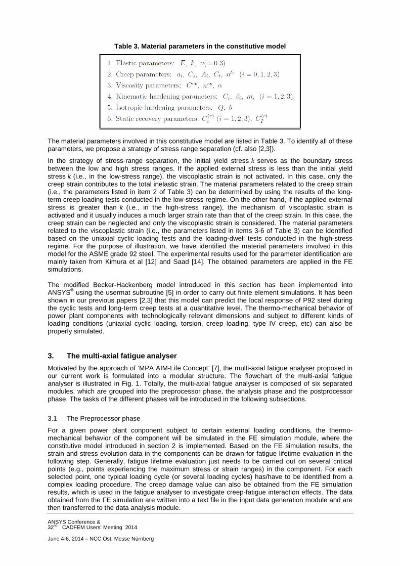
As the first example, we use the fatigue laws introduced in subsection 3.2 to predict the fatigue lifetime of P92 steel in strain-controlled uniaxial cyclic loading tests. The experimental results reported in Mao et al. [21] and Kannan et al. [22], which are obtained at 600°C and different strain ranges, are adopted here for the purpose of validation. By specifying the evolution of the strain tensor at one material point during the cyclic loading tests, the evolution of the stress tensor at that material point can be calculated by using the modified Becker-Hackenberg model. For a typical loading cycle ( � = 300 is selected in this example), the corresponding strain and stress evolution data are selected and serve as input for the analysis phase of the fatigue analyser. The input data are analyzed in the data analysis module to identify the key features, e.g., the maximum normal or shear strain range, the maximum normal stress, the orientation of the critical planes and so on. After that, the FDPs of the different fatigue laws are calculated. The obtained results are then used for the fatigue lifetime evaluation. For P92 steel at 600°C and different uniaxial strain ranges, the predicted results of some fatigue laws are shown in Fig. 3. The criterion of EEPSR presents the same results as the criterion of MNSR, and the criterion of CSH_II is obviously not suitable for the current loading style. Thus, the assessment results of these two laws are not shown in Fig. 3. From Fig. 3, it can be seen that most of the predicted results are located in the region of a factor of 2. The criterions of CSH_I and MPA_AIM provide more conservative predictions compared to the other laws. Although the fatigue cycle numbers predicted by the different fatigue laws have no much differences, it should be noted that the different fatigue laws predict different orientations of the critical planes. For example, the normal vectors of the critical planes predicted by MNSR and CSH_I are aligned with the applied stress, while those predicted by MSSR and FS form an angle of 45° with the direction of the stress. Thus, the orientation of the critical plane should also been taken into account in selecting the appropriate fatigue laws for certain kinds of materials.
ANSYS Conference & 32nd CADFEM Users’ Meeting 2014 June 4-6, 2014 – NCC Ost, Messe Nürnberg
Fig. 3. The results of fatigue lifetime assessment for P92 steel in strain-controlled uniaxial cyclic loading tests (temperature: 600°C; strain ra nges: 0.4%,0.5%,0.6%,0.7%,0.8%,0.9%,1.2%).
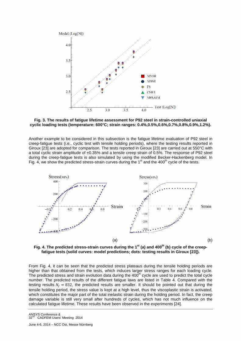
Another example to be considered in this subsection is the fatigue lifetime evaluation of P92 steel in creep-fatigue tests (i.e., cyclic test with tensile holding periods), where the testing results reported in Giroux [23] are adopted for comparison. The tests reported in Giroux [23] are carried out at 550°C with a total cyclic strain amplitude of ±0.35% and a tensile creep strain of 0.5%. The response of P92 steel during the creep-fatigue tests is also simulated by using the modified Becker-Hackenberg model. In Fig. 4, we show the predicted stress-strain curves during the 1st and the 400th cycle of the tests.
(a) (b)
Fig. 4. The predicted stress-strain curves during t he 1st (a) and 400 th (b) cycle of the creep-fatigue tests (solid curves: model predictions; dot s: testing results in Giroux [23]).
From Fig. 4, it can be seen that the predicted stress plateaus during the tensile holding periods are higher than that obtained from the tests, which induces larger stress ranges for each loading cycle. The predicted stress and strain evolution data during the 400th cycle are used to predict the total cycle number. The predicted results of the different fatigue laws are listed in Table 4. Compared with the testing results �� = 832, the predicted results are smaller. It should be pointed out that during the tensile holding period, the stress value is kept at a high level, thus the viscoplastic strain is activated, which constitutes the major part of the total inelastic strain during the holding period. In fact, the creep damage variable is still very small after hundreds of cycles, which has not much influence on the calculated fatigue lifetime. These results have been observed in the experiments [24].

ANSYS Conference & 32nd CADFEM Users’ Meeting 2014 June 4-6, 2014 – NCC Ost, Messe Nürnberg
Table 4. Results of fatigue lifetime prediction of the creep-fatigue tests
Criteria EEPSR MNSR MSSR FS CSH_I MPAAIM
Lifetime 637 636 639 661 612 607
Critical plane
-- (1.00, 0.00, 0.00)
(0.707, 0.00,
0.707)
(0.707, 0.00,
0.707)
(1.00, 0.00, 0.00)
(-0.904, -0.190, -0.383)
4.2 Fatigue lifetime evaluation of a P92 steel tube in cyclic loading tests
In this subsection, we simulate the mechanical behavior of a P92 steel tube in strain-controlled cyclic loading tests. Based on the FE simulation results, the fatigue lifetime of the tube is evaluated by several different fatigue laws. The dimensions of the P92 steel tube are set to be length 1m, inner radius 0.15m and outer radius 0.24m. To conduct the FE simulation, the specimen is meshed with the hexahedral eight-node element (cf. Fig. 5).
Fig. 5. Illustration of the dimensions and the mesh of the P92 steel tube.
We shall study the response of the tube in both the pure axial loading test and the pure torsion test. For convenience, a cylindrical coordinate system is used to represent the positions of the material points in the tube. Suppose one end of the tube (at A = 0B) is fixed. On the other end (at A = 1B), the displacement of a material point is given by D = (∆�, ∆F, ∆A) = (0, HI("), HJ(")), where HI(") = 0 for the pure axial loading test and HJ(") = 0 for the pure torsion test. The temperature of the tube is kept constant at 600°C during the tests. The loading procedures are illustrated in Fig. 6.
Fig. 6. Illustration of the loading styles in the p ure axial loading test and the pure torsion test.

ANSYS Conference & 32nd CADFEM Users’ Meeting 2014 June 4-6, 2014 – NCC Ost, Messe Nürnberg
(a) (b) Fig. 7. (a) Distribution of the axial strain during the pure axial loading test (tensile state);
(b) Distribution of the shear strain during the pur e torsion test.
(a) (b)
(c) (d)
Fig. 8. Results of fatigue lifetime evaluation in t he pure axial loading test: (a) FDP of Criterion FS; (b) fatigue lifetime predicted by Criterion FS; (c) FDP of Criterion MPA_AIM; (d) fatigue
lifetime predicted by Criterion MPA_AIM.

ANSYS Conference & 32nd CADFEM Users’ Meeting 2014 June 4-6, 2014 – NCC Ost, Messe Nürnberg
Based on the results of the FE simulation, we can obtain the distributions of various state variables in the tube. For example, in Fig. 7a we show the distribution of the axial strain in the tube during the pure axial loading test (at a tensile state). It can be seen that the distribution of the axial strain is axisymmetric. Due to the displacement restrictions at the two ends of the tube, the maximum strain value is attained at the middle portion of the tube. In Fig. 7b, we show the distribution of the shear strain in the tube during the pure torsion test. In this case, the distribution of the shear strain is also axisymmetric. However, the maximum strain is obtained on the outer surface of the tube. The stress and strain evolution data during one loading cycle serve as input for the analysis phase of the multi-axial fatigue analyser. In this example, all elements in the tube are taken into account, based on which fatigue lifetime evaluation can be carried out for the whole tube. For the purpose of illustration, the evaluation results (including the FDP and the total number of cycles) of the FS and MPA_AIM criteria are shown in Figs. 8 and 9. For the pure axial loading test, it can be seen from Figs. 8a and 8c that the FDPs of the two criteria attain the maximum values in the middle portion of the tube, which should be induced by the state of axial strain distribution in the tube (cf. Fig 7a). Correspondingly, the minimum fatigue lifetimes are also obtained in the middle portion (cf. Figs. 8b and 8d). For the pure torsion test, as the outer surface of the tube experiences the largest shear strain (cf. Fig 7b), the maximum FDP values and the minimum fatigue lifetimes are obtained at the outer surface of the tube.
(a) (b)
(c) (d)
Fig. 9. Results of fatigue lifetime evaluation in t he pure torsion test: (a) FDP of Criterion FS; (b) Fatigue lifetime predicted by Criterion FS; (c) FDP of Criterion MPA_AIM; (d) fatigue lifetime
predicted by Criterion MPA_AIM.
ANSYS Conference & 32nd CADFEM Users’ Meeting 2014 June 4-6, 2014 – NCC Ost, Messe Nürnberg
5. Conclusions
In this paper, we first introduced the constitutive equations of the modified Becker-Hackenberg model together with the integration algorithm and the strategy for parameter identification. This model was initially proposed to simulate the thermo-mechanical behaviors of high-Cr steel components subject to complex loading conditions. In our previous papers [2,3], it has been shown that this model can predict the local response of P92 steel at a quantitative level. The thermo-mechanical behavior of power plant components with technologically relevant dimensions and subject to different kinds of loading conditions can also be properly simulated. Based on the modified Becker-Hackenberg model, a multiaxial fatigue analyser was proposed to evaluate the fatigue lifetimes of power plant components subject to cyclic loadings. To be applicable to different kinds of materials and loading styles, several representative fatigue laws were implemented in the analyser (e.g., the criterion of equivalent elasto-plastic strain range, the criterion of Fatemi and Socie, the criterion of MPA_AIM, etc). Due to the modular structure of the analyser, new fatigue laws can also be easily implemented without any significant modifications of other modules. Several examples of fatigue lifetime evaluation are introduced in order to show the capabilities of the analyser. The results of the analysis phase can be visualized in the original geometry of the power plant component. Highly stressed regions of the component can easily be identified. Besides the number of cycles to failure, the orientations of critical planes corresponding to the different fatigue laws are also determined. In our future work, the influences of temperature variation and strain styles on the material parameters in the fatigue laws will be investigated. The rain-flow or other counting methods will be used to analyze the input strain and stress data under more complex loading conditions.
6. References
[1] Mohrmann, R.: “Demands on materials and components for existing and new conventional power plants”, 38th MPA-Seminar, Oct. 1-2, 2012 Stuttgart.
[2] Wang, J.; Steinmann, P.; Rudolph, J.; Willuweit, A.: “A combined creep-viscoplastic constitutive model for modeling the thermal-mechanical behavior of high-Cr steel components”, 39th MPA seminar, 8-9 Oct. 2013, Stuttgart.
[3] Wang, J.; Steinmann, P.; Rudolph J.; Willuweit A.: “Simulation of the creep and fatigue damages in high-Cr steel components based on a modified Becker-Hackenberg model”, Proceedings of the ASME 2014 Pressure Vessels & Piping Conference, Paper No. PVP2014-28253
[4] Becker, M.; Hackenberg, H.-P.: “A constitutive model for rate dependent and rate independent inelasticity. Application to IN718”, Int. J. Plast. 27, 2011, pp. 596-619.
[5] ANSYS user material subroutine USERMAT. Mechanics group development department, ANSYS Inc., 1999.
[6] ANSYS Mechanical APDL 14.5, ANSYS Inc. [7] Fesich, T.M.; Roos, E.; Schuler, X.; Herter, K.H.; Krätschmer, D.: „The MPA AIM-life concept for
fatigue evaluation under complex loadings”, 37th MPA Seminar, 6-7 Oct. 2011, Stuttgart. [8] Chaboche, J.L.: “A review of some plasticity and viscoplasticity constitutive theories”,
International Journal of Plasticity 24, 2008, pp. 1642-1693. [9] Chaboche, J.L.: “Constitutive equations for cyclic plasticity and cyclic viscoplasticity”,
International Journal of Plasticity 5, 1989, pp. 247-302. [10] Ohno, N.; Wang, J.D.: “Kinematic hardening rules with critical state of dynamic recovery, part I:
formulation and basic features for ratcheting behavior”, International Journal of Plasticity 9, 1993, pp. 375-390.
[11] Kimura K.; Takahashi, Y.: “Evaluation of long-term creep strength of ASME grades 91, 92 and 122 type steels”, Proceeding of the ASME 2012 Pressure Vessels and Piping Conference, July 15-19, 2012, Toronto, Ontario, Canada.
[12] Kimura, K.; Kanemaru, O.; Sawada, K.; Kushima, H.: Creep deformation and rupture strength property of ASME grades T/P92 Steels, 38th MPA-Seminar, Oct. 1-2, 2012 Stuttgart.
[13] Mathematica 7.0, Wolfram Research, Inc. [14] Saad, A.A.: “Cyclic plasticity and creep of power plant materials”, Doctoral Thesis, the
University of Nottingham, 2012. [15] Karolczuk, A.; Macha, E.: “A review of critical orientations in multiaxial fatigue failure criteria of
metallic materials”, International Journal of Fracture 134, 2005, pp. 267-304.

ANSYS Conference & 32nd CADFEM Users’ Meeting 2014 June 4-6, 2014 – NCC Ost, Messe Nürnberg
[16] Papadopoulos, I.V.: “Critical plane approaches in high-cycle fatigue: on the definition of the amplitude and mean value of the shear stress acting on the critical plane”. Fatigue Fract. Engng. Mater. Struct. 21, 1998, pp. 269-285.
[17] Rudolph, J.; Götz, A.; Hilpert, R.: “Code conforming determination of cumulative usage factors (CUF) for general elastic-plastic finite element analyses”, ANSYS conference & 29th CADFEM User’s meeting, Oct. 2011, Stuttgart, Germany.
[18] Fatemi, A.; Socie, D.F.: “A critical plane approach to multiaxial fatigue damage including out-of phase loading”, Fatigue Fract. Engng Mater. Struct. 11, 149-165.
[19] Chen, X.; Xu, S.; Huang, D.: “A critical plane-strain energy density criterion for multiaxial low-cycle fatigue life under non-proportional loading”, Fatigue Fract. Engng. Mater. Struct. 22, 1999, pp. 679-686.
[20] Gupta, S.K.; Fesich, T.M.; Schuler, X.; Bhasin, V.; Vaze, K.K.; Roos, E.: A critical plane based model for fatigue assessment under fixed and rotating principal direction loading. Transations, SMiRT 21, Nov. 2011. New Delhi, India.
[21] Mao, X.P.; Lu, D.G.; Xu, H.; Zhang, L.Y.; Wang, G.; Xue, F.; Yu, W.W.: “Experimental study on elevated temperature low cycle fatigue of P92 steel” (in Chinese). Atomic Energy Science and Technology 44, 2010, pp. 1212-1216.
[22] Kannan, R.; Sankar, V.; Sandhya, R.; Mathew, M.D.: “Comparative evaluation of low cycle fatigue behaviours of P91 and P92 steels”, Procedia Engineering 55, 2013, pp. 149-153.
[23] Giroux, P.-F.: “Experimental study and simulation of cyclic softening of tempered martensite ferritic steels”, Doctoral Thesis, l'École Nationale Supérieure des Mines de Paris, 2011.
[24] Fournier, B.; Salvi, M.; Dallea, F.; Carlana, Y.; De Caësa, C.; Sauzaya, M.; Pineaub, A.: “Lifetime prediction of 9–12%Cr martensitic steels subjected to creep–fatigue at high temperature”, International Journal of Fatigue 32, 2010, pp. 971–978.
[25] Simo, J.C.; Taylor, R.L.: “Consistent tangent operators for rate-independent elastoplasticity”. Computer Methods in Applied Mechanics and Engineering 48, 1985, pp. 101-118.