Embed Size (px)
Citation preview
TS08C - Engineering Surveying 2 - 6611
Andréa DE SEIXAS, Angela Maria Barbosa de SOUZA, Luciene Ferreira GAMA, Brazil
Implementation and Determination of the Three-dimensional Geodesic Structures in the Olinda’s Historical Site
FIG Working Week 2013
Environment for Sustainability
Abuja, Nigeria, 6 – 10 May 2013
1/16
Implementation and Determination of the Three-Dimensional Geodesic
Structures in the Olinda’s Historical Site
Andréa DE SEIXAS, Angela Maria Barbosa de SOUZA, Luciene Ferreira GAMA,
Brazil
Key words: Three-dimensional geodesic structures, geodesic surveying
SUMMARY
The three-dimensional geodesic structures are fundamental to engineering projects, such as
location and survey of building structures, cadastral surveying, road and railway projects,
positioning and machine control, as also as, monitoring of geodesic structures. These
structures allow the georeferencing and 3D reconstruction of surfaces and objects. A frequent
difficulty in three-dimensional reconstruction and in the topographical/geodesic surveying is
the absence of planialtimetric reference points in the neighborhood of urban and rural
properties in Brazil. One solution for this difficulty is the use of Geodesic Positioning Satellite
System (GNSS - Global Navigation Satellite System) technology, integrated to the
planialtimetric measurements to determine a set of field reference points, which will define
geometrically the elements surveyed on the ground or on the object, these can be natural or
artificial ones. The determination of the inaccessible high points in the architectural
structures, such as targets located in the structures of the churches tower, is very important,
although they are inaccessible, they can be visible from others places and they are more
difficult to be destroyed by human actions. Thus, it is shown to be a relevant study involving
terrestrial methods of measurement, such as: forward and backward intersections, geometric
leveling, trigonometric leveling with short distance targeted, and spatial positioning GNSS
methods, for the definition of field reference points and field-object points located in rough
terrain. The geodesic structures were implemented in the Historic Site of Olinda employing
GNSS receivers, total stations and digital level. The historical site of Olinda was recorded by
UNESCO as Historical and Cultural Heritage of Humanity. The study area is located in the
Center of the busiest site with a quite roughly relief. This area has been studied since 2007
involving Research of Scientific Initiation and Pos-Graduation Course. This paper aims to
present the realized experiments for the implementation and definition of geodesic structures
in environments with very rough relief, including large old houses and historic monuments.
RESUMO
As estruturas geodésicas tridimensionais são fundamentais para os projetos de Engenharia,
tais como: locação e levantamento de estruturas de edificações prediais, levantamentos
cadastrais, traçados de rodovias e ferrovias, posicionamento e controle de máquinas, assim
como, monitoramento de estruturas geodésicas. Estas estruturas permitem o
georreferenciamento e reconstrução 3D de superfícies e de objetos. Uma dificuldade
freqüente na reconstrução tridimensional e nos levantamentos topográficos/geodésicos é a
TS08C - Engineering Surveying 2 - 6611
Andréa DE SEIXAS, Angela Maria Barbosa de SOUZA, Luciene Ferreira GAMA, Brazil
Implementation and Determination of the Three-dimensional Geodesic Structures in the Olinda’s Historical Site
FIG Working Week 2013
Environment for Sustainability
Abuja, Nigeria, 6 – 10 May 2013
2/16
ausência de pontos de referência planialtimétricos nas proximidades dos imóveis urbanos e
rurais brasileiros. Uma solução para essa dificuldade é a utilização da tecnologia de
Posicionamento Geodésico por Satélite (GNSS – Global Navigation Satellite System)
integrado a medições terrestres planialtimétricas para definição de um conjunto de campo de
pontos de referência, o qual definirá geometricamente os elementos levantados sobre a
superfície do terreno e do objeto, estes podendo ser objetos naturais ou artificiais. A
determinação de pontos altos inacessíveis nas estruturas arquitetônicas, como por exemplo,
alvos contidos nas estruturas de edificação situados em torres de igrejas, é importante, pois
apesar de serem inacessíveis, tornam-se visíveis de outras localidades e mais difíceis de serem
obstruídos por ações antrópicas. Com isso, mostra-se ser de relevância um estudo envolvendo
os métodos terrestres de medição, tais como: interseção à vante e à ré; nivelamento
geométrico, nivelamento trigonométrico com visadas curtas; e métodos de posicionamento
espacial GNSS, para a definição de campo de pontos de referência e campo de pontos-objeto
localizados em terrenos acidentados. As estruturas geodésicas foram implantadas no Sítio
Histórico de Olinda empregando-se receptores GNSS, Estações Totais e Nível Digital. O Sítio
Histórico de Olinda foi tombado pela UNESCO como Patrimônio Histórico e Cultural da
Humanidade. A área em estudo localiza-se no Centro de maior movimentação comercial e
com relevo bastante ondulado. Essa área vem sendo estudada desde 2007 envolvendo
pesquisas de Iniciação Científica e de Mestrado. Este trabalho tem como objetivo a
apresentação dos experimentos realizados para a implantação e definição de estruturas
geodésicas em ambientes diversificados pelo relevo acidentado, caracterizada pela construção
de casarios antigos e monumentos históricos.
TS08C - Engineering Surveying 2 - 6611
Andréa DE SEIXAS, Angela Maria Barbosa de SOUZA, Luciene Ferreira GAMA, Brazil
Implementation and Determination of the Three-dimensional Geodesic Structures in the Olinda’s Historical Site
FIG Working Week 2013
Environment for Sustainability
Abuja, Nigeria, 6 – 10 May 2013
3/16
Implementation and Determination of the Three-Dimensional Geodesic
Structures in the Olinda’s Historical Site
Andréa DE SEIXAS, Angela Maria Barbosa de SOUZA, Luciene Ferreira GAMA,
Brazil
1. INTRODUCTION
The three-dimensional geodesic structures are fundamental to engineering projects, such as:
location and surveys of building structures, cadastral surveying, road and railway projects,
positioning and machine control, and monitoring of deformations of geodesic structures
themselves, allowing the georeferencing and the 3D reconstruction of terrestrial topographical
surfaces, artificial objects, for example, building constructions.
A frequent difficulty in the three-dimensional reconstruction and topographical/ geodesic
surveying, is the lack of planialtimetric reference points near the urban and rural properties.
One solution for this difficulty is the use of Geodesic Positioning Satellite System technology
(GNSS - Global Navigation Satellite System) integrated to the terrestrial planialtimétric
measurements for definition of a set of field reference points that will define geometrically
elements surveyed on the surface of ground and natural or artificial objects, located in a given
reference system.
The determination of the high points in inaccessible architectural structures, such as target of
the buildings located on church towers is very important in one geodesic structure, despite of
being inaccessible from other locations, are visible in the others places and will be more
protected by devastation of human actions. Thus, it is more relevantly to a study involving
methods of terrestrial measurements, such as: forward and backward intersection, geometric
leveling, trigonometric leveling with short sights, electronic tacheometry, in addition to the
geodesic positioning satellite to the field reference points definition and field object points
located in rough terrain. The aim of this paper is to present the methodology used for the
implementation and definition of the three-dimensional geodesic structures to present three-
dimensional buildings located in urban sites with the presence of rough relief making use of
planialtimetric measurement methods.
The experiments were conducted in the area of the Historic Site of Olinda, called Area Test.
The geodesic structures implanted in Olinda Historic Site were measured three-dimensionally
and densified employing GNSS receivers, Total Station and Digital Level. In the following
will be approached the three-dimensional geodesic structures and planialtimetric measurement
methods.
2. THREE-DIMENSIONAL GEODESIC STRUCTURES
Three-dimensional geodesic structures can be defined as fields of planialtimetric points
materialized and accurate. These fields of points represent the reference for the establishment
of geodetic positions to arrive at global, regional and local (TORGE, 2003). Three-
dimensional geodesic structures are formed by planialtimetrics geodesic networks and
TS08C - Engineering Surveying 2 - 6611
Andréa DE SEIXAS, Angela Maria Barbosa de SOUZA, Luciene Ferreira GAMA, Brazil
Implementation and Determination of the Three-dimensional Geodesic Structures in the Olinda’s Historical Site
FIG Working Week 2013
Environment for Sustainability
Abuja, Nigeria, 6 – 10 May 2013
4/16
gravimetric networks. In this paper will be treated local three-dimensional geodesic
structures.These are implemnted primarily for engineering projects, among other geophysical
investigations and for geodynamic procedures determination spatially limited (TORGE,
2003).
The definition and implementation of geodesic structures are dependent on technological
developments. Therefore, it will be visualized distinct measurement procedures,
materialization and points detection. Then the geodesic structures have one-dimensional, two-
dimensional and/or three-dimensional character. In SOUZA (2012) and GAMA (2008) are
approached the geodesic structures employed in this work.
3. PLANIALTIMETRIC MEASUREMENT METHODS
For the field reference points measurement, in the present paper, it was employed
planialtimetric methods of surveying such as: GNSS, forward and backward intersection, as
well as, geometric and trigonometric leveling with short sights.
3.1 Static Relative Positioning Method of GNSS
The relative positioning can be obtained by the static method. The static method generally,
uses the double phase difference (DD) as observable. Two or more receivers collect data
simultaneously from the satellites for at least twenty (20) minutes to a few hours. Enables an
accuracy around 1.0 to 0.1 ppm or better than that. For extensive baselines (greater than 15
km) are employed receivers with dual frequency (MONICO, 2008).
For relative positioning are assigned to various methods, among them can be mencioned the
static and "stop-and-go" methods. Further information regarding to these methods are
acquired in the following bibliographical references: (SEEBER, 2003), (MONICO, 2000),
(LEICK, 1995), (SEGANTINE, 2002) and (HOFMANN-WELLENHOF et al., 2001).
General Standards and Specifications for GPS Surveys by IBGE, PR Resolution 22, of
7/21/83, refer to these surveying methods and determine the conditions to be applyed in all
surveys with GPS in Brazil.
3.2 Terrestrial Planialtimetric of Measurement Methods with Total Station
In this paper the terrestrial measurement methods are interconnected to the positioning
satellite methods. In the following are defined the used terrestrial measurement methods.
They are ordered according to the types of observations made by the Total Station. The
determination of the planimetric coordinates were separated of the altimetric determination.
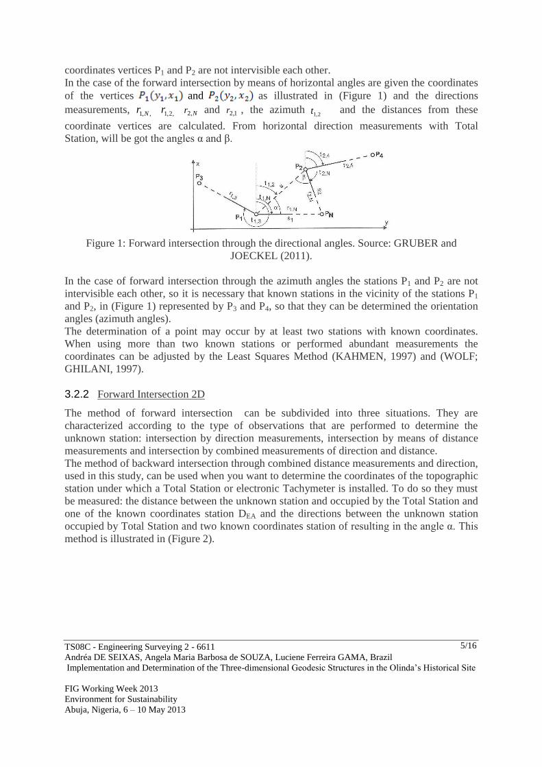
3.2.1 Forward Intersection Method 2D
Two cases were approached in (SOUZA, 2012). At the first forward intersection occurs by
internal angles measurrments and (Figure 1) belonging to the triangle formed between the
known coordinates vertices of P1 and P2 and the unknown PN. In this case the known
coordinates vertices with P1 and P2 are intervisible each other. In the second the forward
intersection occurs by directional angle measurements the (Figure 1), in this case the known
TS08C - Engineering Surveying 2 - 6611
Andréa DE SEIXAS, Angela Maria Barbosa de SOUZA, Luciene Ferreira GAMA, Brazil
Implementation and Determination of the Three-dimensional Geodesic Structures in the Olinda’s Historical Site
FIG Working Week 2013
Environment for Sustainability
Abuja, Nigeria, 6 – 10 May 2013
5/16
coordinates vertices P1 and P2 are not intervisible each other.
In the case of the forward intersection by means of horizontal angles are given the coordinates
of the vertices and as illustrated in (Figure 1) and the directions
measurements, ,,1 Nr ,2,1r Nr ,2 and 1,2r , the azimuth
2,1t and the distances from these
coordinate vertices are calculated. From horizontal direction measurements with Total
Station, will be got the angles α and β.
Figure 1: Forward intersection through the directional angles. Source: GRUBER and
JOECKEL (2011).
In the case of forward intersection through the azimuth angles the stations P1 and P2 are not
intervisible each other, so it is necessary that known stations in the vicinity of the stations P1
and P2, in (Figure 1) represented by P3 and P4, so that they can be determined the orientation
angles (azimuth angles).
The determination of a point may occur by at least two stations with known coordinates.
When using more than two known stations or performed abundant measurements the
coordinates can be adjusted by the Least Squares Method (KAHMEN, 1997) and (WOLF;
GHILANI, 1997).
3.2.2 Forward Intersection 2D
The method of forward intersection can be subdivided into three situations. They are
characterized according to the type of observations that are performed to determine the
unknown station: intersection by direction measurements, intersection by means of distance
measurements and intersection by combined measurements of direction and distance.
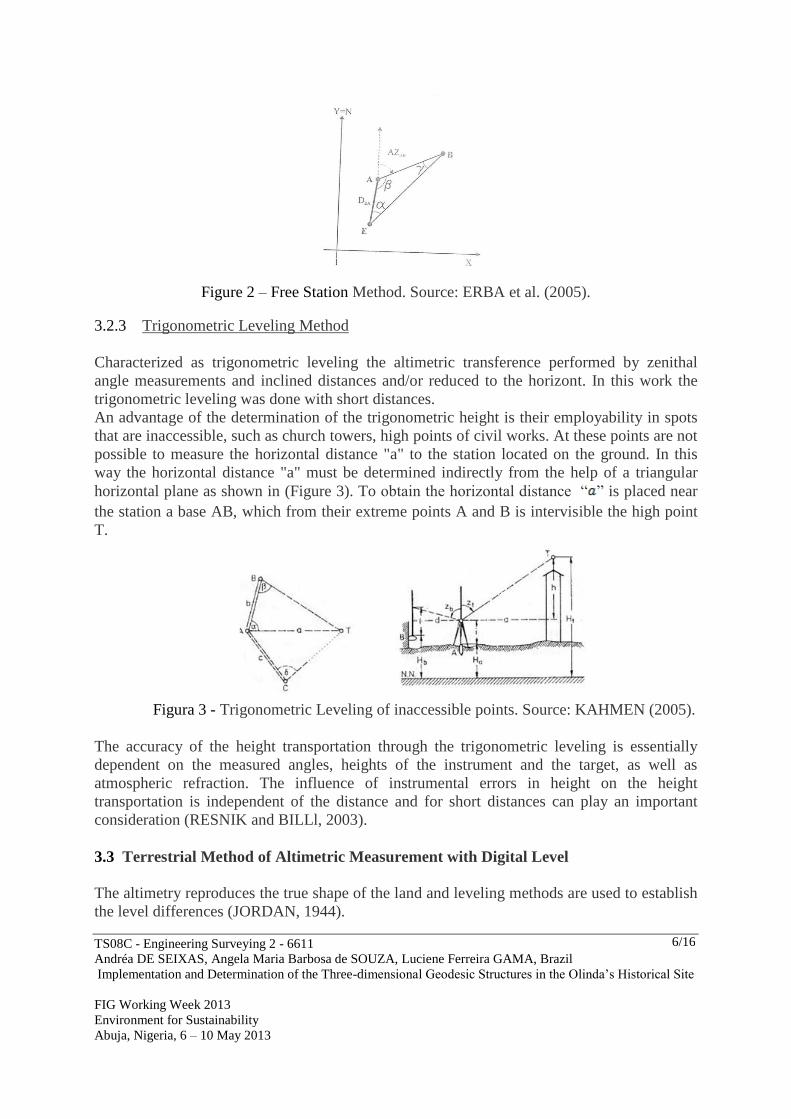
The method of backward intersection through combined distance measurements and direction,
used in this study, can be used when you want to determine the coordinates of the topographic
station under which a Total Station or electronic Tachymeter is installed. To do so they must
be measured: the distance between the unknown station and occupied by the Total Station and
one of the known coordinates station DEA and the directions between the unknown station
occupied by Total Station and two known coordinates station of resulting in the angle α. This
method is illustrated in (Figure 2).
TS08C - Engineering Surveying 2 - 6611
Andréa DE SEIXAS, Angela Maria Barbosa de SOUZA, Luciene Ferreira GAMA, Brazil
Implementation and Determination of the Three-dimensional Geodesic Structures in the Olinda’s Historical Site
FIG Working Week 2013
Environment for Sustainability
Abuja, Nigeria, 6 – 10 May 2013
6/16
Figure 2 – Free Station Method. Source: ERBA et al. (2005).
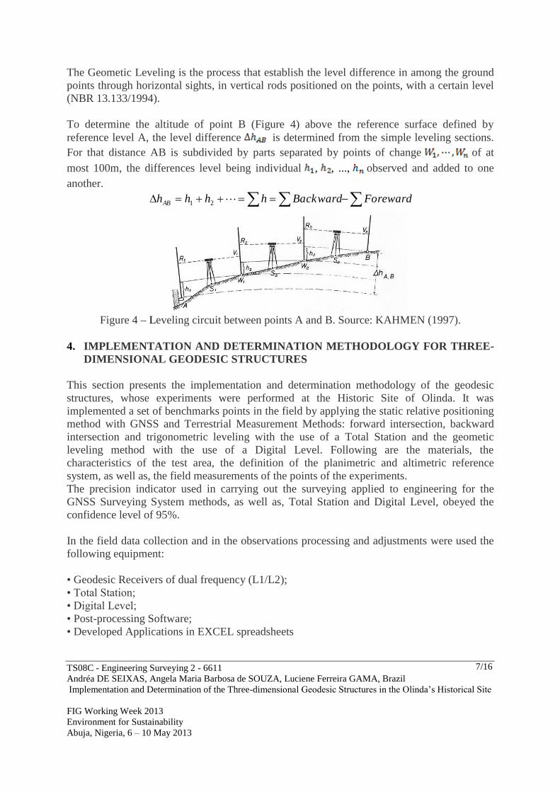
3.2.3 Trigonometric Leveling Method
Characterized as trigonometric leveling the altimetric transference performed by zenithal
angle measurements and inclined distances and/or reduced to the horizont. In this work the
trigonometric leveling was done with short distances.
An advantage of the determination of the trigonometric height is their employability in spots
that are inaccessible, such as church towers, high points of civil works. At these points are not
possible to measure the horizontal distance "a" to the station located on the ground. In this
way the horizontal distance "a" must be determined indirectly from the help of a triangular
horizontal plane as shown in (Figure 3). To obtain the horizontal distance “ ” is placed near
the station a base AB, which from their extreme points A and B is intervisible the high point
T.
Figura 3 - Trigonometric Leveling of inaccessible points. Source: KAHMEN (2005).
The accuracy of the height transportation through the trigonometric leveling is essentially
dependent on the measured angles, heights of the instrument and the target, as well as
atmospheric refraction. The influence of instrumental errors in height on the height
transportation is independent of the distance and for short distances can play an important
consideration (RESNIK and BILLl, 2003).
3.3 Terrestrial Method of Altimetric Measurement with Digital Level
The altimetry reproduces the true shape of the land and leveling methods are used to establish
the level differences (JORDAN, 1944).
TS08C - Engineering Surveying 2 - 6611
Andréa DE SEIXAS, Angela Maria Barbosa de SOUZA, Luciene Ferreira GAMA, Brazil
Implementation and Determination of the Three-dimensional Geodesic Structures in the Olinda’s Historical Site
FIG Working Week 2013
Environment for Sustainability
Abuja, Nigeria, 6 – 10 May 2013
7/16
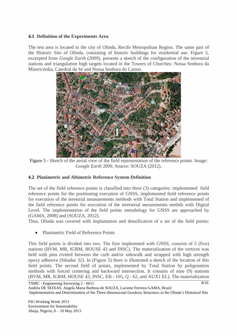
The Geometic Leveling is the process that establish the level difference in among the ground
points through horizontal sights, in vertical rods positioned on the points, with a certain level
(NBR 13.133/1994).
To determine the altitude of point B (Figure 4) above the reference surface defined by
reference level A, the level difference is determined from the simple leveling sections.
For that distance AB is subdivided by parts separated by points of change of at
most 100m, the differences level being individual , , ..., observed and added to one
another.
ForewardBackwardhhhhAB 21
Figure 4 – Leveling circuit between points A and B. Source: KAHMEN (1997).
4. IMPLEMENTATION AND DETERMINATION METHODOLOGY FOR THREE-
DIMENSIONAL GEODESIC STRUCTURES
This section presents the implementation and determination methodology of the geodesic
structures, whose experiments were performed at the Historic Site of Olinda. It was
implemented a set of benchmarks points in the field by applying the static relative positioning
method with GNSS and Terrestrial Measurement Methods: forward intersection, backward
intersection and trigonometric leveling with the use of a Total Station and the geometic
leveling method with the use of a Digital Level. Following are the materials, the
characteristics of the test area, the definition of the planimetric and altimetric reference
system, as well as, the field measurements of the points of the experiments.
The precision indicator used in carrying out the surveying applied to engineering for the
GNSS Surveying System methods, as well as, Total Station and Digital Level, obeyed the
confidence level of 95%.
In the field data collection and in the observations processing and adjustments were used the
following equipment:
• Geodesic Receivers of dual frequency (L1/L2);
• Total Station;
• Digital Level;
• Post-processing Software;
• Developed Applications in EXCEL spreadsheets
TS08C - Engineering Surveying 2 - 6611
Andréa DE SEIXAS, Angela Maria Barbosa de SOUZA, Luciene Ferreira GAMA, Brazil
Implementation and Determination of the Three-dimensional Geodesic Structures in the Olinda’s Historical Site
FIG Working Week 2013
Environment for Sustainability
Abuja, Nigeria, 6 – 10 May 2013
8/16
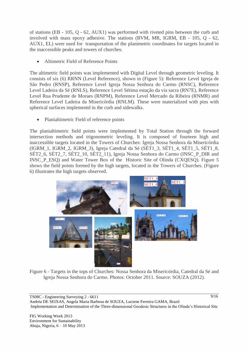
4.1 Definition of the Experiments Area
The test area is located in the city of Olinda, Recife Metropolitan Region. The same part of
the Historic Site of Olinda, consisting of historic buildings for residential use. Figure 5,
excerpted from Google Earth (2009), presents a sketch of the configuration of the terrestrial
stations and triangulation high targets located in the Towers of Churches: Nossa Senhora da
Misericórdia, Catedral da Sé and Nossa Senhora do Carmo.
Figure 5 - Sketch of the aerial view of the field representation of the reference points. Image:
Google Earth 2009. Source: SOUZA (2012).
4.2 Planimetric and Altimetric Reference System Definition
The set of the field reference points is classified into three (3) categories: implemented field
reference points for the positioning execution of GNSS, implemented field reference points
for execution of the terestrial measurements methods with Total Station and implemented of
the field reference points for execution of the terrestrial mesurements methds with Digital
Level. The implementetion of the field points metodology for GNSS are approached by
(GAMA, 2008) and (SOUZA, 2012).
Thus, Olinda was covered with implantation and densification of a set of the field points:
Planimetric Field of Reference Points
This field points is divided into two. The first implemnted with GNSS, consists of 5 (five)
stations (BVM, MR, IGRM, HOUSE 43 and INSC). The materialization of the vertices was
held with pins riveted between the curb and/or sidewalk and wrapped with high strength
epoxy adhesive (Sikadur 32). In (Figure 5) there is illustrated a sketch of the location of this
field points. The second field of points, implemented by Total Station by poligonation
methods with forced centering and backward intersection. It consists of nine (9) stations
(BVM, MR, IGRM, HOUSE 43, INSC, EB - 105, Q - 62, and AUX1 EL). The materialization
TS08C - Engineering Surveying 2 - 6611
Andréa DE SEIXAS, Angela Maria Barbosa de SOUZA, Luciene Ferreira GAMA, Brazil
Implementation and Determination of the Three-dimensional Geodesic Structures in the Olinda’s Historical Site
FIG Working Week 2013
Environment for Sustainability
Abuja, Nigeria, 6 – 10 May 2013
9/16
of stations (EB - 105, Q - 62, AUX1) was performed with riveted pins between the curb and
involved with mass epoxy adhesive. The stations (BVM, MR, IGRM, EB - 105, Q - 62,
AUX1, EL) were used for transportation of the planimetric coordinates for targets located in
the inaccessible peaks and towers of churches.
Altimetric Field of Reference Points
The altimetric field points was implemented with Digital Level through geometric leveling. It
consists of six (6) RRNN (Level Reference), shown in (Figure 5): Reference Level Igreja de
São Pedro (RNSP), Reference Level Igreja Nossa Senhora do Carmo (RNSC), Reference
Level Ladeira da Sé (RNLS), Reference Level Sétima estação da via sacra (RN7E), Reference
Level Rua Prudente de Moraes (RNPM), Reference Level Mercado da Ribeira (RNMR) and
Reference Level Ladeira da Misericórdia (RNLM). These were materialized with pins with
spherical surfaces implementd in the curb and sidewalks.
Planialtimetric Field of reference points
The planialtimetric field points were implemented by Total Station through the forward
intersection methods and trigonometric leveling. It is composed of fourteen high and
inaccessible targets located in the Towers of Churches: Igreja Nossa Senhora da Misericórdia
(IGRM_1, IGRM_2, IGRM_3), Igreja Catedral da Sé (SÉT1_3, SÉT1_4, SÉT1_5, SÉT1_8,
SÉT2_6, SÉT2_7, SÉT2_10, SÉT2_11), Igreja Nossa Senhora do Carmo (INSC_P_DIR and
INSC_P_ESQ) and Water Tower Box of the Historic Site of Olinda (CXQESQ). Figure 5
shows the field points formed by the high targets, located in the Towers of Churches. (Figure
6) illustrates the high targets observed.
Figure 6 - Targets in the tops of Churches: Nossa Senhora da Misericórdia, Catedral da Sé and
Igreja Nossa Senhora do Carmo. Photos: October 2011. Source: SOUZA (2012).
TS08C - Engineering Surveying 2 - 6611
Andréa DE SEIXAS, Angela Maria Barbosa de SOUZA, Luciene Ferreira GAMA, Brazil
Implementation and Determination of the Three-dimensional Geodesic Structures in the Olinda’s Historical Site
FIG Working Week 2013
Environment for Sustainability
Abuja, Nigeria, 6 – 10 May 2013
10/16
For the determination of the altimetric coordinates of the high targets, were used the
orthometric height of the reference points, determined from a network leveling, compose the
altimetric field reference points implemented in the test area.
Below is discussed the implementation set of the field reference points.
4.3 Field Points Measurement
4.3.1 Field Reference Points Measurement with GNSS
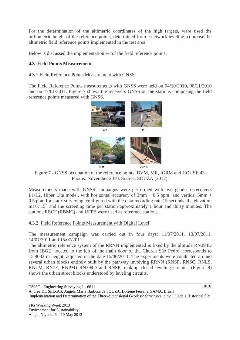
The Field Reference Points measurements with GNSS were held on 04/10/2010, 08/11/2010
and on 17/01/2011. Figure 7 shows the receivers GNSS on the stations composing the field
reference points measured with GNSS.
Figure 7 - GNSS occupation of the reference points: BVM, MR, IGRM and HOUSE 43.
Photos: November 2010. Source: SOUZA (2012).
Measurements made with GNSS campaigns were performed with two geodesic receivers
L1/L2, Hiper Lite model, with horizontal accuracy of 3mm + 0.5 ppm and vertical 5mm +
0.5 ppm for static surveying, configured with the data recording rate 15 seconds, the elevation
mask 15° and the screening time per station approximately 1 hour and thirty minutes. The
stations RECF (RBMC) and UFPE were used as reference stations.
4.3.2 Field Reference Points Measurement with Digital Level
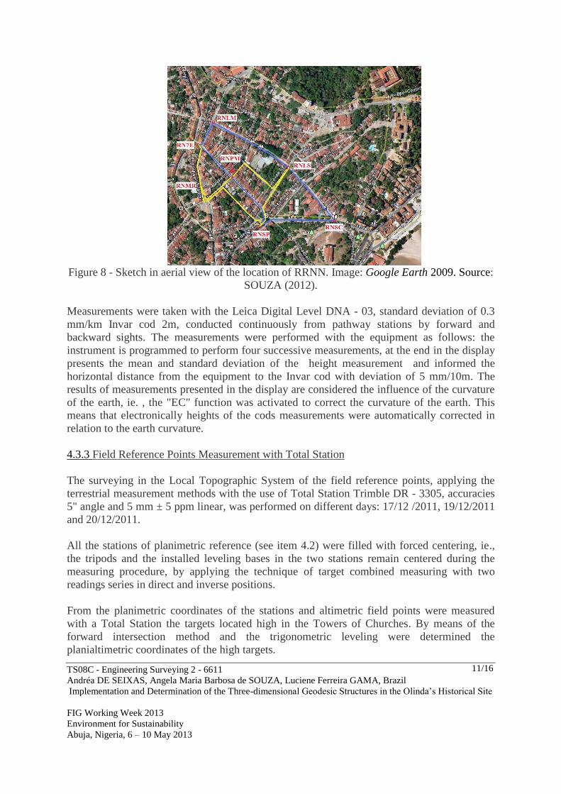
The measurement campaign was carried out in four days: 11/07/2011, 13/07/2011,
14/07/2011 and 15/07/2011.
The altimetric reference system of the RRNN implemented is fixed by the altitude RN394D
from IBGE, located to the left of the main door of the Church São Pedro, corresponds to
15.9082 m height, adjusted in the date 15/06/2011. The experiments were conducted around
several urban blocks entirely built by the pathway involving RRNN (RNSP, RNSC, RNLS,
RNLM, RN7E, RNPM) RN394D and RNSP, making closed leveling circuits. (Figure 8)
shows the urban street blocks understood by leveling circuits.
TS08C - Engineering Surveying 2 - 6611
Andréa DE SEIXAS, Angela Maria Barbosa de SOUZA, Luciene Ferreira GAMA, Brazil
Implementation and Determination of the Three-dimensional Geodesic Structures in the Olinda’s Historical Site
FIG Working Week 2013
Environment for Sustainability
Abuja, Nigeria, 6 – 10 May 2013
11/16
Figure 8 - Sketch in aerial view of the location of RRNN. Image: Google Earth 2009. Source:
SOUZA (2012).
Measurements were taken with the Leica Digital Level DNA - 03, standard deviation of 0.3
mm/km Invar cod 2m, conducted continuously from pathway stations by forward and
backward sights. The measurements were performed with the equipment as follows: the
instrument is programmed to perform four successive measurements, at the end in the display
presents the mean and standard deviation of the height measurement and informed the
horizontal distance from the equipment to the Invar cod with deviation of 5 mm/10m. The
results of measurements presented in the display are considered the influence of the curvature
of the earth, ie. , the "EC" function was activated to correct the curvature of the earth. This
means that electronically heights of the cods measurements were automatically corrected in
relation to the earth curvature.
4.3.3 Field Reference Points Measurement with Total Station
The surveying in the Local Topographic System of the field reference points, applying the
terrestrial measurement methods with the use of Total Station Trimble DR - 3305, accuracies
5" angle and 5 mm ± 5 ppm linear, was performed on different days: 17/12 /2011, 19/12/2011
and 20/12/2011.
All the stations of planimetric reference (see item 4.2) were filled with forced centering, ie.,
the tripods and the installed leveling bases in the two stations remain centered during the
measuring procedure, by applying the technique of target combined measuring with two
readings series in direct and inverse positions.
From the planimetric coordinates of the stations and altimetric field points were measured
with a Total Station the targets located high in the Towers of Churches. By means of the
forward intersection method and the trigonometric leveling were determined the
planialtimetric coordinates of the high targets.
TS08C - Engineering Surveying 2 - 6611
Andréa DE SEIXAS, Angela Maria Barbosa de SOUZA, Luciene Ferreira GAMA, Brazil
Implementation and Determination of the Three-dimensional Geodesic Structures in the Olinda’s Historical Site
FIG Working Week 2013
Environment for Sustainability
Abuja, Nigeria, 6 – 10 May 2013
12/16
The high targets of the towers of the Catedral da Sé were measured at their left and right
extremes because they had a spherical shape. The targets of the high tower of the Igreja Nossa
Senhora da Misericórdia and the targets of he high tower of the Igreja Nossa Senhora do
Carmo were measured in their extreme points (SOUZA, 2012).
The angular and linear measurements for the planimetric stations and for the Level References
were made with a prism installed in the in "basis - prism" adapter in the first case and a
vertical stick supported on a tripod in the second case. Thus it was possible to carry the
RRNN altitude for other high targets observed.
From the high targets were possible by the backward intersection method to determine and
compare the planimetric coordinates of the some stations of the planimetric field of reference
points. And by the trigonometric leveling method verify the quality of the altitudes
transferred from of the high targets to the Level References without considering the height of
the instrument. This was possible because near each planimetric station there is a Reference
Level.
5. RESULTS
Following are the results for the high targets located in the Towers of Churches of Nossa
Senhora do Carmo, Nossa Senhora da Misericórdia and Catedral da Sé.
1) Planimetric coordinates of high targets determined by the forward intersection method of
the 2D
The planimetric coordinates of high targets: IGRM_1, IGRM_2, IGRM_3, SÉT1_3, SÉT1_4,
SÉT1_5, SÉT1_8, SÉT2_6, SÉT2_7, SÉT2_10, SÉT2_11, INSC_P_ESQ, INSC_P_DIR and
CXQESQ were calculated using developed applications in EXCEL spreadsheet software. The
resulting coordinates for these high targets are achieved by the average values of the
observations of the angles reading in the edges left and right of the spherical structures located
in the towers of the Catedral da Sé. For other targets coordinates are obtained by the mean
values of the observations of the reading angles. In (SOUZA, 2012) described the whole
procedure for the forward intersection method. Table 1 shows the determined coordinates and
their respective standard deviations.
Table 1 - Coordinates UTM SIRGAS2000 determined by forward intersecting 2D and their
respectives standard deviations. Source: SOUZA (2012).
2) Planimetric coordinates of the reference stations determined by backward intersection 2D
TS08C - Engineering Surveying 2 - 6611
Andréa DE SEIXAS, Angela Maria Barbosa de SOUZA, Luciene Ferreira GAMA, Brazil
Implementation and Determination of the Three-dimensional Geodesic Structures in the Olinda’s Historical Site
FIG Working Week 2013
Environment for Sustainability
Abuja, Nigeria, 6 – 10 May 2013
13/16
through combined measurements of direction and distance
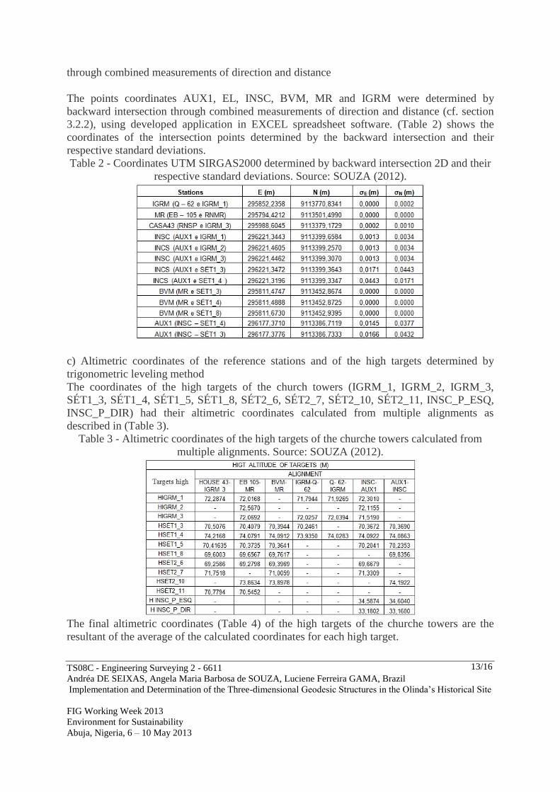
The points coordinates AUX1, EL, INSC, BVM, MR and IGRM were determined by
backward intersection through combined measurements of direction and distance (cf. section
3.2.2), using developed application in EXCEL spreadsheet software. (Table 2) shows the
coordinates of the intersection points determined by the backward intersection and their
respective standard deviations.
Table 2 - Coordinates UTM SIRGAS2000 determined by backward intersection 2D and their
respective standard deviations. Source: SOUZA (2012).
c) Altimetric coordinates of the reference stations and of the high targets determined by
trigonometric leveling method
The coordinates of the high targets of the church towers (IGRM_1, IGRM_2, IGRM_3,
SÉT1_3, SÉT1_4, SÉT1_5, SÉT1_8, SÉT2_6, SÉT2_7, SÉT2_10, SÉT2_11, INSC_P_ESQ,
INSC_P_DIR) had their altimetric coordinates calculated from multiple alignments as
described in (Table 3).
Table 3 - Altimetric coordinates of the high targets of the churche towers calculated from
multiple alignments. Source: SOUZA (2012).
The final altimetric coordinates (Table 4) of the high targets of the churche towers are the
resultant of the average of the calculated coordinates for each high target.
TS08C - Engineering Surveying 2 - 6611
Andréa DE SEIXAS, Angela Maria Barbosa de SOUZA, Luciene Ferreira GAMA, Brazil
Implementation and Determination of the Three-dimensional Geodesic Structures in the Olinda’s Historical Site
FIG Working Week 2013
Environment for Sustainability
Abuja, Nigeria, 6 – 10 May 2013
14/16
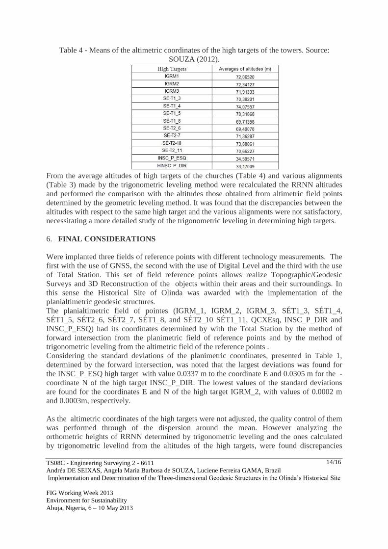
Table 4 - Means of the altimetric coordinates of the high targets of the towers. Source:
SOUZA (2012).
From the average altitudes of high targets of the churches (Table 4) and various alignments
(Table 3) made by the trigonometric leveling method were recalculated the RRNN altitudes
and performed the comparison with the altitudes those obtained from altimetric field points
determined by the geometric leveling method. It was found that the discrepancies between the
altitudes with respect to the same high target and the various alignments were not satisfactory,
necessitating a more detailed study of the trigonometric leveling in determining high targets.
6. FINAL CONSIDERATIONS
Were implanted three fields of reference points with different technology measurements. The
first with the use of GNSS, the second with the use of Digital Level and the third with the use
of Total Station. This set of field reference points allows realize Topographic/Geodesic
Surveys and 3D Reconstruction of the objects within their areas and their surroundings. In
this sense the Historical Site of Olinda was awarded with the implementation of the
planialtimetric geodesic structures.
The planialtimetric field of pointes (IGRM_1, IGRM_2, IGRM_3, SÉT1_3, SÉT1_4,
SÉT1_5, SÉT2_6, SÉT2_7, SÉT1_8, and SÉT2_10 SÉT1_11, QCXEsq, INSC_P_DIR and
INSC_P_ESQ) had its coordinates determined by with the Total Station by the method of
forward intersection from the planimetric field of reference points and by the method of
trigonometric leveling from the altimetric field of the reference points .
Considering the standard deviations of the planimetric coordinates, presented in Table 1,
determined by the forward intersection, was noted that the largest deviations was found for
the INSC_P_ESQ high target with value 0.0337 m to the coordinate E and 0.0305 m for the -
coordinate N of the high target INSC_P_DIR. The lowest values of the standard deviations
are found for the coordinates E and N of the high target IGRM_2, with values of 0.0002 m
and 0.0003m, respectively.
As the altimetric coordinates of the high targets were not adjusted, the quality control of them
was performed through of the dispersion around the mean. However analyzing the
orthometric heights of RRNN determined by trigonometric leveling and the ones calculated
by trigonometric levelind from the altitudes of the high targets, were found discrepancies
TS08C - Engineering Surveying 2 - 6611
Andréa DE SEIXAS, Angela Maria Barbosa de SOUZA, Luciene Ferreira GAMA, Brazil
Implementation and Determination of the Three-dimensional Geodesic Structures in the Olinda’s Historical Site
FIG Working Week 2013
Environment for Sustainability
Abuja, Nigeria, 6 – 10 May 2013
15/16
unacceptable for most high targets, with exception for the targets INSC_P_ESQ,
INSC_P_DIR and SÉT1_4 whose their discrepancies were around 1cm.
ACKNOWLEDGEMENT
Prof. Titular José Jorge de Seixas by English translation.
LATOP/DECart/UFPE
LAGEO/DECart/UFPE
REFERENCES
1. TORGE, W. Geodaesie, 2. Aufage, Berlin: de Gruyter Lehrbuch, 2003.
2. MONICO, J. F. G. Posicionamento pelo GNSS: descrição, fundamentos e
aplicações.2 ed. - São Paulo: Editora UNESP, 2008.
3. KAHMEN, H. Vermessungskunde. 19. Aufl., 1997.
4. GRUBER, F. J.; JOECKEL, R. Formelsammlung fuer das Vermessungswesen. 15.
Auflage. Studium Viemegt: Teubner, 2011.
5. WOLF, P. R.; GHILANI, C. D. Adjustment Computations Statistics and Least
Squares in Surveying and GIS. New York. John Wiley & Sons Inc,1997.
6. GEMAEL, C. Introdução ao Ajustamento de Observações: aplicações
geodésicas.Curitiba: Ed.UFPR,1994. Reimpressão 2004.
7. GAMA, L. F. Experimentos e Análises Metodológicas do Desempenho de
Estruturas Geodésicas Planimétricas Implantadas com GPS e Estação Total:
Aplicações em Levantamentos Cadastrais Urbanos. Dissertação de Mestrado
apresentado ao Programa de Pós-Graduação em Ciências Geodésicas e Tecnologias da
Geoinformação da UFPE. Recife. 2008.
8. KAHMEN, H.; FAIG, W. Surveying. Berlin: Ed. de Gruyter, 1988.
9. JORDAN, D. W. Tratado general de Topografia. V. I. Barcelona, Editorial Gustavo
Gili, S. A.,1944.
10. RESNIK, B.; BILL, R. Vermessungskunde fuer den Plannungs-, Bau- und
Unweltbereich. 3. Aulf. Wichmann Verlag: Heidelberg, 2003.
11. KAHMEN, H. Angewandete Geodaesie. Vermessungskunde. 20. Aufl., 2005.
12. ABNT. NBR-13.133 – Normas Técnicas para a Execução de Levantamentos
Topográficos. Rio de Janeiro, 1994.
13. SEEBER, G. Satellite Geodesy: Fundamentations, Methods and Applications.
Walter de Gruyter, Berlin, New York, 2003.
14. HOFMANN-WELLENHOF, B.; LICHTENEGGER, H.; COLLINS, J. GPS: Theory
and Practice. Springer Wien New York. 3ª.ed. 389 P. 2001.
15. MONICO, J. F. Galera. Posicionamento pelo NAVSTAR – GPS: Descrição,
Fundamentos e Aplicações. Editora UNESP – São Paulo, 2000.
16. LEICK, A. GPS: Satellite surveying. 2. ed. New York: J.Wiley, 1995. 560p.
17. SEGANTINE, P.C.L. Sistema de Posicionamento Global - GPS. São Carlos. Editora
da Escola de Engenharia de São Carlos, Universidade de São Paulo. 2002. 316 p.
18. IBGE. Resolução - PR nº 22, de 21-07-83 - Especificações e Normas Gerais para
Levantamentos Geodésicos, 1983 – www.ibge.gov.br (acessado em 02/07/2011).
TS08C - Engineering Surveying 2 - 6611
Andréa DE SEIXAS, Angela Maria Barbosa de SOUZA, Luciene Ferreira GAMA, Brazil
Implementation and Determination of the Three-dimensional Geodesic Structures in the Olinda’s Historical Site
FIG Working Week 2013
Environment for Sustainability
Abuja, Nigeria, 6 – 10 May 2013
16/16
19. ERBA, D. A. (ORG.); THUM, A. B.; SILVA, C. A. U. de; SOUZA, G. C. de;
VERONZ, M. R.; LENADRO, R. F.; MAIA, T. C. B. Curso de Topografia para
estudantes de Engenharia, Arquitetura e Geologia. Editora Unissinos, 2005.
20. SOUZA, A. M. B. Análise e comparação de estruturas geodésicas tridimensionais
definidas por métodos planialtimétricos de medição. Dissertação de mestrado
apresentado ao Programa de Pós-Graduação em Ciências Geodésicas e Tecnologias da
Geoinformação da UFPE. Recife. 2012.
CONTACTS
Dr.techn. Engª. Cartógrafa Andréa DE SEIXAS (Professor Adjunto IV)
Universidade Federal de Pernambuco
Centro de Tecnologia e Geociências
Departamento de Engenharia Cartográfica
Programa de Pós-Graduação em Ciências Geodésicas e Tecnologias da Geoinformação
Av. Acadêmico Hélio Ramos s/n° - Cidade Universitária
Recife –PE, 50740-530
BRASIL
Tel. +55 081 2126 7946; Fax + 55 081 21268235
Email: [email protected]; Web site: www.ufpe.br/cgtg
MSc. Engª. Cartógrafa Angela Maria Barbosa de SOUZA
Agência Estadual de Planejamento e Pesquisas de Pernambuco CONDEPE/FIDEM
Rua Barão São Borja,526 Boa Vista
Recife - PE
BRASIL
Tel. + 55 081 31824522
Email: [email protected]
Web site: www.condepefidem.pe.gov.br
MSc. Engª. Agrimensora Luciene Ferreira GAMA (Professor Assistente)
Instituto Federal de Educação, Ciência e Tecnologia da Paraíba
Unidade de Design, Infraestrutura e Meio Ambiente
Curso Superior de Tecnologia em Geoprocessamento
Av. 1º de Maio, 720, Jaguaribe, João Pessoa - PB - CEP: 58.015-430
BRASIL
Tel. 55 83 3208.3000; Fax: 55 83 3208.3088
Email: [email protected]; Web site: http://www.ifpb.edu.br
![[Abstract] Determination of Tariff for Wheeling Contracts ...profdoc.um.ac.ir/articles/a/1025198.pdf · 714-192 Risk Management Methods for Service Oriented Architecture Implementation](https://img.pdfslide.net/doc/110x75/5e87567a1db21309f02919d2/abstract-determination-of-tariff-for-wheeling-contracts-714-192-risk-management.jpg)